EP3868645A1 - Schiffsantriebssystem und steuerungsverfahren - Google Patents
Schiffsantriebssystem und steuerungsverfahren Download PDFInfo
- Publication number
- EP3868645A1 EP3868645A1 EP21156894.4A EP21156894A EP3868645A1 EP 3868645 A1 EP3868645 A1 EP 3868645A1 EP 21156894 A EP21156894 A EP 21156894A EP 3868645 A1 EP3868645 A1 EP 3868645A1
- Authority
- EP
- European Patent Office
- Prior art keywords
- marine propulsion
- drive mode
- engine
- under
- propulsion device
- Prior art date
- Legal status (The legal status is an assumption and is not a legal conclusion. Google has not performed a legal analysis and makes no representation as to the accuracy of the status listed.)
- Granted
Links
Images


Classifications
-
- B—PERFORMING OPERATIONS; TRANSPORTING
- B60—VEHICLES IN GENERAL
- B60L—PROPULSION OF ELECTRICALLY-PROPELLED VEHICLES; SUPPLYING ELECTRIC POWER FOR AUXILIARY EQUIPMENT OF ELECTRICALLY-PROPELLED VEHICLES; ELECTRODYNAMIC BRAKE SYSTEMS FOR VEHICLES IN GENERAL; MAGNETIC SUSPENSION OR LEVITATION FOR VEHICLES; MONITORING OPERATING VARIABLES OF ELECTRICALLY-PROPELLED VEHICLES; ELECTRIC SAFETY DEVICES FOR ELECTRICALLY-PROPELLED VEHICLES
- B60L50/00—Electric propulsion with power supplied within the vehicle
- B60L50/50—Electric propulsion with power supplied within the vehicle using propulsion power supplied by batteries or fuel cells
- B60L50/60—Electric propulsion with power supplied within the vehicle using propulsion power supplied by batteries or fuel cells using power supplied by batteries
- B60L50/66—Arrangements of batteries
-
- B—PERFORMING OPERATIONS; TRANSPORTING
- B63—SHIPS OR OTHER WATERBORNE VESSELS; RELATED EQUIPMENT
- B63H—MARINE PROPULSION OR STEERING
- B63H1/00—Propulsive elements directly acting on water
- B63H1/02—Propulsive elements directly acting on water of rotary type
- B63H1/12—Propulsive elements directly acting on water of rotary type with rotation axis substantially in propulsive direction
- B63H1/14—Propellers
-
- B—PERFORMING OPERATIONS; TRANSPORTING
- B63—SHIPS OR OTHER WATERBORNE VESSELS; RELATED EQUIPMENT
- B63H—MARINE PROPULSION OR STEERING
- B63H20/00—Outboard propulsion units, e.g. outboard motors or Z-drives; Arrangements thereof on vessels
- B63H20/14—Transmission between propulsion power unit and propulsion element
-
- B—PERFORMING OPERATIONS; TRANSPORTING
- B63—SHIPS OR OTHER WATERBORNE VESSELS; RELATED EQUIPMENT
- B63H—MARINE PROPULSION OR STEERING
- B63H21/00—Use of propulsion power plant or units on vessels
- B63H21/12—Use of propulsion power plant or units on vessels the vessels being motor-driven
- B63H21/14—Use of propulsion power plant or units on vessels the vessels being motor-driven relating to internal-combustion engines
-
- B—PERFORMING OPERATIONS; TRANSPORTING
- B63—SHIPS OR OTHER WATERBORNE VESSELS; RELATED EQUIPMENT
- B63H—MARINE PROPULSION OR STEERING
- B63H21/00—Use of propulsion power plant or units on vessels
- B63H21/12—Use of propulsion power plant or units on vessels the vessels being motor-driven
- B63H21/17—Use of propulsion power plant or units on vessels the vessels being motor-driven by electric motor
-
- B—PERFORMING OPERATIONS; TRANSPORTING
- B63—SHIPS OR OTHER WATERBORNE VESSELS; RELATED EQUIPMENT
- B63H—MARINE PROPULSION OR STEERING
- B63H21/00—Use of propulsion power plant or units on vessels
- B63H21/20—Use of propulsion power plant or units on vessels the vessels being powered by combinations of different types of propulsion units
-
- B—PERFORMING OPERATIONS; TRANSPORTING
- B63—SHIPS OR OTHER WATERBORNE VESSELS; RELATED EQUIPMENT
- B63H—MARINE PROPULSION OR STEERING
- B63H21/00—Use of propulsion power plant or units on vessels
- B63H21/21—Control means for engine or transmission, specially adapted for use on marine vessels
-
- F—MECHANICAL ENGINEERING; LIGHTING; HEATING; WEAPONS; BLASTING
- F02—COMBUSTION ENGINES; HOT-GAS OR COMBUSTION-PRODUCT ENGINE PLANTS
- F02B—INTERNAL-COMBUSTION PISTON ENGINES; COMBUSTION ENGINES IN GENERAL
- F02B61/00—Adaptations of engines for driving vehicles or for driving propellers; Combinations of engines with gearing
- F02B61/04—Adaptations of engines for driving vehicles or for driving propellers; Combinations of engines with gearing for driving propellers
- F02B61/045—Adaptations of engines for driving vehicles or for driving propellers; Combinations of engines with gearing for driving propellers for marine engines
-
- F—MECHANICAL ENGINEERING; LIGHTING; HEATING; WEAPONS; BLASTING
- F02—COMBUSTION ENGINES; HOT-GAS OR COMBUSTION-PRODUCT ENGINE PLANTS
- F02B—INTERNAL-COMBUSTION PISTON ENGINES; COMBUSTION ENGINES IN GENERAL
- F02B63/00—Adaptations of engines for driving pumps, hand-held tools or electric generators; Portable combinations of engines with engine-driven devices
- F02B63/04—Adaptations of engines for driving pumps, hand-held tools or electric generators; Portable combinations of engines with engine-driven devices for electric generators
- F02B63/042—Rotating electric generators
-
- B—PERFORMING OPERATIONS; TRANSPORTING
- B60—VEHICLES IN GENERAL
- B60L—PROPULSION OF ELECTRICALLY-PROPELLED VEHICLES; SUPPLYING ELECTRIC POWER FOR AUXILIARY EQUIPMENT OF ELECTRICALLY-PROPELLED VEHICLES; ELECTRODYNAMIC BRAKE SYSTEMS FOR VEHICLES IN GENERAL; MAGNETIC SUSPENSION OR LEVITATION FOR VEHICLES; MONITORING OPERATING VARIABLES OF ELECTRICALLY-PROPELLED VEHICLES; ELECTRIC SAFETY DEVICES FOR ELECTRICALLY-PROPELLED VEHICLES
- B60L2200/00—Type of vehicles
- B60L2200/32—Waterborne vessels
-
- B—PERFORMING OPERATIONS; TRANSPORTING
- B63—SHIPS OR OTHER WATERBORNE VESSELS; RELATED EQUIPMENT
- B63H—MARINE PROPULSION OR STEERING
- B63H21/00—Use of propulsion power plant or units on vessels
- B63H21/20—Use of propulsion power plant or units on vessels the vessels being powered by combinations of different types of propulsion units
- B63H2021/202—Use of propulsion power plant or units on vessels the vessels being powered by combinations of different types of propulsion units of hybrid electric type
- B63H2021/205—Use of propulsion power plant or units on vessels the vessels being powered by combinations of different types of propulsion units of hybrid electric type the second power unit being of the internal combustion engine type, or the like, e.g. a Diesel engine
-
- B—PERFORMING OPERATIONS; TRANSPORTING
- B63—SHIPS OR OTHER WATERBORNE VESSELS; RELATED EQUIPMENT
- B63H—MARINE PROPULSION OR STEERING
- B63H21/00—Use of propulsion power plant or units on vessels
- B63H21/21—Control means for engine or transmission, specially adapted for use on marine vessels
- B63H2021/216—Control means for engine or transmission, specially adapted for use on marine vessels using electric control means
-
- Y—GENERAL TAGGING OF NEW TECHNOLOGICAL DEVELOPMENTS; GENERAL TAGGING OF CROSS-SECTIONAL TECHNOLOGIES SPANNING OVER SEVERAL SECTIONS OF THE IPC; TECHNICAL SUBJECTS COVERED BY FORMER USPC CROSS-REFERENCE ART COLLECTIONS [XRACs] AND DIGESTS
- Y02—TECHNOLOGIES OR APPLICATIONS FOR MITIGATION OR ADAPTATION AGAINST CLIMATE CHANGE
- Y02T—CLIMATE CHANGE MITIGATION TECHNOLOGIES RELATED TO TRANSPORTATION
- Y02T10/00—Road transport of goods or passengers
- Y02T10/60—Other road transportation technologies with climate change mitigation effect
- Y02T10/70—Energy storage systems for electromobility, e.g. batteries
Definitions
- the present invention relates to a marine propulsion system and a control method thereof.
- the marine propulsion system is configured to rotate the propeller shaft only by a drive force of the electric motor in an extremely low speed range and is also configured to rotate the propeller shaft by a drive force of the engine when a speed exceeds a predetermined speed.
- the electric motor is supplied with electric power through a battery from a power generator that generates the electric power when driven by the engine.
- said object is solved by a marine propulsion system having the features of independent claim 1 and/or by method of controlling a marine propulsion having the features of independent claim 15. Preferred embodiments are laid down in the dependent claims.
- a marine propulsion system includes a marine propulsion device, a battery and a controller.
- the marine propulsion device includes a propeller shaft, an engine and an electric motor.
- the marine propulsion device transmits a mechanical power from at least one of the engine and the electric motor to the propeller shaft.
- the battery supplies an electric power to the electric motor.
- the controller controls the marine propulsion device such that the marine propulsion device is switchable among a plurality of drive modes including a first drive mode and a second drive mode.
- the first drive mode brings about a state where the mechanical power is transmitted from only the engine to the propeller shaft.
- the second drive mode brings about a state where the mechanical power is transmitted from only the electric motor to the propeller shaft when the engine is in an idling state.
- a method relates to a method of controlling a marine propulsion system including a marine propulsion device and a battery.
- the marine propulsion device includes a propeller shaft, an engine and an electric motor.
- the marine propulsion device transmits a mechanical power from at least one of the engine and the electric motor to the propeller shaft.
- the battery supplies an electric power to the electric motor.
- the method includes controlling the marine propulsion device such that the marine propulsion device is switchable among a plurality of drive modes including a first drive mode and a second drive mode.
- the first drive mode brings about a state where the mechanical power is transmitted from only the engine to the propeller shaft.
- the second drive mode brings about a state where the mechanical power is transmitted from only the electric motor to the propeller shaft when the engine is in an idling state.
- the engine is controlled in the idling state under the second drive mode bringing about the state where the drive force is transmitted from only the electric motor to the propeller shaft. Hence, it is possible to achieve enhancement in merchantability of the marine propulsion system.
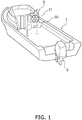
- FIG. 1 is a perspective view of a watercraft 1 including a marine propulsion system 100 according to a first preferred embodiment.
- FIG. 2 is a block diagram showing a configuration of the marine propulsion system 100.
- the marine propulsion system 100 includes an outboard motor 2, a power generator 3, a battery 4, a marine operating device 5 and a controller 6.
- the outboard motor 2 is an exemplary marine propulsion device.
- the outboard motor 2 generates a thrust for propelling the watercraft 1.
- the outboard motor 2 is attached to the middle of the stern of the watercraft 1.
- FIG. 3 is a side view of the outboard motor 2.
- the outboard motor 2 includes a propeller shaft 10, an engine 11, a drive shaft 12, an engine clutch 13, an electric motor 14, a motor shaft 15 and a motor clutch 16.
- mechanical power is transmitted from at least one of the engine 11 and the electric motor 14 to the propeller shaft 10.
- mechanical power is transmitted from either one of the engine 11 and the electric motor 14 to the propeller shaft 10.
- the propeller shaft 10 extends in the back-and-forth direction of the watercraft 1.
- a propeller 18 that rotates integrally with the propeller shaft 10 is attached to the propeller shaft 10.
- the drive shaft 12 extends in the vertical direction.
- the drive shaft 12 is rotated when driven by the engine 11.
- the engine clutch 13 connects or disconnects the drive shaft 12 and the propeller shaft 10 to or from each other. Besides, the engine clutch 13 switches a rotational direction of the propeller shaft 10.
- the engine clutch 13 includes a drive gear 13a, a forward moving gear 13b, a rearward moving gear 13c, and a dog clutch 13d.
- the drive gear 13a is rotated integrally with the drive shaft 12.
- the forward moving gear 13b and the rearward moving gear 13c are meshed with the drive gear 13a. Rotation of the drive shaft 12 is transmitted to the forward moving gear 13b and the rearward moving gear 13c through the drive gear 13a.
- the dog clutch 13d is movable to a forward moving position, a neutral position, and a rearward moving position.
- the forward moving gear 13b is connected to the propeller shaft 10, whereby rotation of the drive shaft 12 is transmitted to the propeller shaft 10 through the forward moving gear 13b.
- the dog clutch 13d is set in the neutral position, the propeller shaft 10 is disconnected from the forward moving gear 13b and the rearward moving gear 13c, whereby rotation of the drive shaft 12 is not transmitted to the propeller shaft 10.
- the dog clutch 13d is set in the rearward moving position, the rearward moving gear 13c is connected to the propeller shaft 10, whereby rotation of the drive shaft 12 is transmitted to the propeller shaft 10 through the rearward moving gear 13c.
- the electric motor 14 is driven by electric power supplied thereto from the battery 4.
- the motor shaft 15 extends in parallel to the drive shaft 12.
- the motor shaft 15 is rotated when driven by the electric motor 14.
- the motor clutch 16 connects or disconnects the motor shaft 15 and the propeller shaft 10 to or from each other.
- the motor clutch 16 is movable to a connecting position or a disconnecting position. When the motor clutch 16 is set in the connecting position, rotation of the motor shaft 15 is transmitted to the propeller shaft 10 through a motor gear (not shown in the drawings). When the motor clutch 16 is set in the disconnecting position, the propeller shaft 10 is disconnected from the motor gear, whereby rotation of the motor shaft 15 is not transmitted to the propeller shaft 10.
- the power generator 3 generates electric power when driven by the engine 11.
- the power generator 3 supplies the electric power generated therein to the battery 4.
- the power generator 3 is disposed inside the outboard motor 2 and is connected to the engine 11.
- the power generator 3 includes a rotor and a stator.
- the power generator 3 generates electric power when the rotor, connected to the drive shaft 12, is rotated with respect to the stator. It should be noted that the power generator 3 may supply the electric power generated therein not only to the battery 4 but also to the electric motor 14.
- the battery 4 is connected to the outboard motor 2.
- the battery 4 stores the electric power generated in the power generator 3 and supplies the electric power stored therein to the electric motor 14. It should be noted that the battery 4 and the controller 6 may be connected to supply the electric power stored in the battery 4 to the controller 6.
- the marine operating device 5 is disposed in a cockpit 30 set on the watercraft 1. As shown in FIG. 2 , the marine operating device 5 includes a steering device 31, a throttle lever 32 and a plurality of switches 33.
- the steering device 31 is a device for operating a turning direction of the watercraft 1.
- the throttle lever 32 is an operating member for regulating the thrust generated by the outboard motor 2 and switching the direction of the thrust between forward and rearward directions.
- the plurality of switches 33 include a switch for starting the engine 11, a switch for setting a vessel speed, and a switch for switching the outboard motor 2 among a plurality of drive modes.
- the marine operating device 5 is connected to the controller 6 through wired or wireless communication. When the marine operating device 5 is operated, an operating signal is outputted from the marine operating device 5 to the controller 6.
- the controller 6 controls the outboard motor 2.
- the controller 6 controls the outboard motor 2 in accordance with the operating signal outputted thereto from the marine operating device 5.
- the controller 6 includes a processor such as a CPU and memories such as a RAM and a ROM.
- the controller 6 stores programs and data for controlling the outboard motor 2.
- the controller 6 may be disposed inside the outboard motor 2, or alternatively, may be disposed outside the outboard motor 2.
- the controller 6 controls the outboard motor 2 such that the outboard motor 2 can be switched among the plurality of drive modes.
- the controller 6 moves the engine clutch 13 and the motor clutch 16 through an actuator, whereby the outboard motor 2 is switched among the drive modes.
- the controller 6 controls driving and output of the engine 11 and/or those of the electric motor 14 in accordance with the operating position of the throttle lever 32 and the operating statuses of the switches 33.
- FIG. 4 is a diagram exemplifying patterns for switching the outboard motor 2 among the plurality of drive modes.
- the plurality of drive modes at least include a first drive mode (F) and a second drive mode (M).
- the first drive mode brings about a state where the mechanical power is transmitted from only the engine 11 to the propeller shaft 10.
- the second drive mode brings about a state where the mechanical power is transmitted from only the electric motor 14 to the propeller shaft 10 while the engine 11 is in an idling state.
- the plurality of drive modes may further include a third drive mode bringing about a state where the mechanical power is transmitted from only the electric motor 14 to the propeller shaft 10, while the engine 11 is in a stop state.
- the plurality of drive modes may include a drive mode bringing about a state where the mechanical power is transmitted from both the engine 11 and the electric motor 14 to the propeller shaft 10.
- FIG. 4 also exemplifies patterns for switching a plurality of outboard motors 2 among a plurality of drive modes. The patterns will be described in detail.
- the first drive mode is used in propelling the watercraft 1 in a high speed range.
- the engine 11 is a mechanical power source.
- the electric motor 14 is not driven.
- the controller 6 controls the output of the engine 11 in accordance with the operating position of the throttle lever 32.
- the second and third drive modes are used in propelling the watercraft 1 in an extremely low speed range.
- the electric motor 14 is a mechanical power source.
- the controller 6 controls the engine 11 in the idling state.
- the engine 11 is controlled in the idling state by the controller 6.
- electric power is generated by the power generator 3.
- shortage of electric power supply to the electric motor 14 can be inhibited.
- the watercraft 1 can cruise in the extremely low speed range for a long period of time.
- the rotational speed of the electric motor 14 under the second drive mode is set to be lower than that of the engine 11 in the idling state.
- the controller 6 may limit the output of the electric motor 14 to a constant value except for when the mechanical power source is switched from the electric motor 14 to the engine 11. Alternatively, the controller 6 may control the output of the electric motor 14 to be changed in accordance with the operating position of the throttle lever 32 and the operating statuses of the switches 33.
- the third drive mode is different from the second drive mode only in that the engine 11 is controlled in the stop state by the controller 6.
- the third drive mode is effective in a quietness required situation such as docking.
- the controller 6 may switch the plurality of drive modes according to the operating amount of the throttle lever 32, the vessel speed, or combination thereof. Alternatively, the controller 6 may switch the plurality of drive modes according to the operating the switches 33.
- the controller 6 may drive the outboard motor 2 under the second drive mode.
- the controller 6 may drive the outboard motor 2 under the first drive mode.
- the marine propulsion system 100 may further include a speed detector 7 detecting the vessel speed.
- the controller 6 may switch the outboard motor 2 from the first drive mode to the second drive mode.
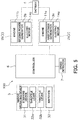
- FIG. 5 is a block diagram showing a configuration the marine propulsion system 100 according to a second preferred embodiment.
- the following explanation will be given for constituent elements different from corresponding ones in the first preferred embodiment; explanation will be omitted for constituent elements similar to corresponding ones in the first preferred embodiment. It should be noted that reference signs assigned to constituent elements in FIG. 5 are the same as those assigned to corresponding ones in the first preferred embodiment.
- two outboard motors composed of a first outboard motor 2a and a second outboard motor 2b, are provided as the outboard motors 2.
- the first outboard motor 2a is attached to the port of the stern of the watercraft 1.
- the first outboard motor 2a is an exemplary first marine propulsion device.
- the second outboard motor 2b is attached to the starboard of the stern of the watercraft 1, while being aligned in parallel to the first outboard motor 2a.
- the second outboard motor 2b is an exemplary second marine propulsion device.
- the first outboard motor 2a when described in detail, includes an engine 11a and an electric motor 14a.
- the second outboard motor 2b includes an engine 11b and an electric motor 14b.
- Each engine 11a, 11b has a similar configuration to the engine 11.
- Each electric motor 14a, 14b has a similar configuration to the electric motor 14.
- a first power generator 3a and a second power generator 3b are provided as the power generators 3.
- the first power generator 3a generates electric power when driven by the engine 11a of the first outboard motor 2a.
- the second power generator 3b generates electric power when driven by the engine 11b of the second outboard motor 2b.
- the battery 4 stores electric power generated by the first power generator 3a and that generated by the second power generator 3b, and supplies the electric power stored therein to the electric motor 14a of the first outboard motor 2a and the electric motor 14b of the second outboard motor 2b.
- the marine operating device 5 includes a throttle lever 32a and a throttle lever 32b.
- the throttle lever 32a is an operating member for regulating a thrust generated by the first outboard motor 2a and switching the direction of the thrust between forward and rearward directions.
- the throttle lever 32b is an operating member for regulating a thrust generated by the second outboard motor 2b and switching the direction of the thrust between forward and rearward directions.
- the controller 6 controls the first and second outboard motors 2a and 2b such that the first and second outboard motors 2a and 2b can be switched among a plurality of drive modes.
- the plurality of drive modes include at least a fourth drive mode shown by (4) in FIG. 4 in addition to the first and second drive modes described above. Under the fourth drive mode, the first and second outboard motors 2a and 2b are alternately driven in the state brought about under the second drive mode.
- the controller 6 alternately drives the first and second outboard motors 2a and 2b in the state brought about under the second drive mode, for instance, at intervals of predetermined time.
- the fourth drive mode is used in propelling the watercraft 1 in the extremely low speed range.
- the controller 6 preferably controls the engine of the other of the first and second outboard motors 2a and 2b in the idling state.
- the controller 6 preferably controls the engine 11b of the second outboard motor 2b in the idling state and simultaneously controls the electric motor 14b of the second outboard motor 2b in the stop state. At this time, the dog clutch 13d of the second outboard motor 2b is controlled to be set in the neutral position by the controller 6.
- the second outboard motor 2b set as “N” by (4) in FIG. 4 will be exemplified to explain the meaning of "N".
- the engine 11b is controlled in the idling state by the controller 6, the electric motor 14b is controlled in the stop state, and the dog clutch 13d of the second outboard motor 2b is controlled to be set in the neutral position.
- Such a state will be hereinafter explained as an N state.
- the controller 6 controls the second outboard motor 2b in the N state.
- the controller 6 controls the first outboard motor 2a in the N state.
- electric power is generated by both the first and second power generators 3a and 3b. Hence, shortage of electric power supply to the electric motors 14a and 14b can be inhibited.
- the controller 6 may stop the engine 11b of the second outboard motor 2b.
- the controller 6 may stop the engine 11a of the first outboard motor 2a.
- the plurality of drive modes may further include a fifth drive mode, under which the first and second outboard motors 2a and 2b are alternately driven in the state brought about under the first drive mode.
- a fifth drive mode under which the first and second outboard motors 2a and 2b are alternately driven in the state brought about under the first drive mode.
- the controller 6 controls the other of the first and second outboard motors 2a and 2b in the state brought about under the second drive mode.
- the plurality of drive modes may further include a drive mode, under which both the first and second outboard motors 2a and 2b are driven in the state brought about under the second drive mode.
- the plurality of drive modes may include the third drive mode bringing about a state where the engine 11a, 11b is controlled in the stop state by the controller 6 in a similar manner to the first preferred embodiment.
- the plurality of drive modes may include a drive mode bringing about a state where the mechanical power is transmitted from both the engine 11a, 11b and the electric motor 14a, 14b to the propeller shaft 10.
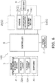
- FIG. 6 is a block diagram showing a configuration of the marine propulsion system 100 according to a third preferred embodiment.
- the following explanation will be given for constituent elements different from corresponding ones in the second preferred embodiment; explanation will be omitted for constituent elements similar to corresponding ones in the second preferred embodiment. It should be noted that reference signs assigned to constituent elements in FIG. 6 are the same as those assigned to corresponding ones in the second preferred embodiment.
- three outboard motors including a third outboard motor 2c in addition to the two outboard motors described above, are provided as the outboard motors 2.
- the third outboard motor 2c is an exemplary third marine propulsion device.
- the third outboard motor 2c is attached to the middle of the stern of the watercraft 1.
- the third outboard motor 2c is disposed between the first and second outboard motors 2a and 2b.
- the third outboard motor 2c has a similar configuration to the outboard motor 2.
- the third outboard motor 2c includes an engine 11c and an electric motor 14c.
- the engine 11c has a similar configuration to the engine 11.
- the electric motor 14c has a similar configuration to the electric motor 14.
- a third power generator 3c is further provided as an additional power generator 3.
- the third power generator 3c generates electric power when driven by the engine 11c of the third outboard motor 2c.
- the battery 4 stores electric power generated by the third power generator 3c in addition to electric power generated by the first power generator 3a and that generated by the second power generator 3b, and supplies the electric power stored therein to the electric motor 14c of the third outboard motor 2c.
- the controller 6 regulates a thrust generated by the third outboard motor 2c and switches the direction of the thrust in accordance with operating the throttle lever 32a, 32b.
- the controller 6 controls the third outboard motor 2c such that the third outboard motor 2c can be switched among a plurality of drive moves.
- the plurality of drive modes further include sixth to ninth drive modes shown by (6) to (9) in FIG. 4 in addition to the first and second drive modes described above.
- the first and second outboard motors 2a and 2b are driven in the state brought about under the first drive mode
- the third outboard motor 2c is driven in the state brought about under the second drive mode.
- the first and second outboard motors 2a and 2b are driven in the state brought about under the fourth drive mode, whereas the third outboard motor 2c is driven in the state brought about under the first drive mode.
- electric power is generated by the third power generator 3c and at least one of the first and second power generators 3a and 3b. Hence, shortage of electric power supply to the electric motor 14a, 14b can be inhibited.
- both the engine 11a of the first outboard motor 2a and the engine 11b of the second outboard motor 2b are controlled in the idling state, whereas only the third outboard motor 2c is driven in the state brought about under the first drive mode.
- both the engine 11a of the first outboard motor 2a and the engine 11b of the second outboard motor 2b are controlled in the idling state by the controller 6.
- both the first and second outboard motors 2a and 2b are controlled in the N state.
- both the engine 11a of the first outboard motor 2a and the engine 11b of the second outboard motor 2b are controlled in the idling state, whereas only the third outboard motor 2c is driven in the state brought about under the second drive mode.
- both the engine 11a of the first outboard motor 2a and the engine 11b of the second outboard motor 2b are controlled in the idling state by the controller 6.
- both the first and second outboard motors 2a and 2b are controlled in the N state.
- the plurality of drive modes may further include a drive mode, under which the first, second and third outboard motors 2a, 2b and 2c are all controlled in the state brought about under the second drive mode.
- the plurality of drive modes may include the third drive mode bringing about a state where each engine 11a, 11b, 11c is controlled in the stop state by the controller 6.
- the plurality of drive modes may include a drive mode bringing about a state where the mechanical power is transmitted from both the engine 11a, 11b, 11c and the electric motor 14a, 14b, 14c to the relevant propeller shaft 10.
- the outboard motors 2a to 2d are sequentially disposed on the stern of the watercraft 1 from the port to the starboard in the order of the third outboard motor 2c, the first outboard motor 2a, the second outboard motor 2b and the fourth outboard motor 2d.
- the first and second outboard motors 2a and 2b are controlled in the state brought about under the fifth drive mode, whereas the third and fourth outboard motors 2c and 2d are controlled in the state brought about under the first drive mode.
- the first and second outboard motors 2a and 2b are controlled in the state brought about under the fourth drive mode, whereas the third and fourth outboard motors 2c and 2d are controlled in the state brought about under the first drive mode.
- the first and second outboard motors 2a and 2b are controlled in the state brought about under the first drive mode, whereas at least one of the third and fourth outboard motors 2c and 2d is controlled in the N state.
- both the third and fourth outboard motors 2c and 2d are controlled in the N state.
- the plurality of drive modes further include a drive mode (omitted in illustration), under which the first and second outboard motors 2a and 2b are controlled in the state brought about under the fourth or fifth drive mode, whereas at least one of the third and fourth outboard motors 2c and 2d is controlled in the N state.
- the plurality of drive modes may include drive modes similar to those in the first to third preferred embodiments.
- the outboard motors 2a to 2e are sequentially disposed on the stern of the watercraft 1 from the port to the starboard in the order of the fourth outboard motor 2d, the first outboard motor 2a, the third outboard motor 2c, the second outboard motor 2b and the fifth outboard motor 2e.
- the first, second and third outboard motors 2a, 2b and 2c are controlled in the state brought about under the sixth drive mode, whereas the fourth and fifth outboard motors 2d and 2e are controlled in the state brought about under the first drive mode.
- the first, second and third outboard motors 2a, 2b and 2c are controlled in the state brought about under the seventh drive mode, whereas the fourth and fifth outboard motors 2d and 2e are controlled in the state brought about under the first drive mode.
- the first, second and third outboard motors 2a, 2b and 2c are controlled in the state brought about under the first drive mode, whereas at least one of the fourth and fifth outboard motors 2d and 2e is controlled in the N state. It should be noted that in the configuration shown in FIG. 4 , under the drive mode (15), both the fourth and fifth outboard motors 2d and 2e are controlled in the N state.
- the plurality of drive modes further include a drive mode (omitted in illustration), under which the first, second and third outboard motors 2a, 2b and 2c are controlled in the state brought about under any of the sixth to ninth drive modes, whereas at least one of the fourth and fifth outboard motors 2d and 2e is controlled in the N state.
- the plurality of drive modes may include drive modes similar to those in the first to third preferred embodiments.
- FIG. 7 is a block diagram showing a configuration of the marine propulsion system 100 according to a modification.
- the modification is different from the first preferred embodiment regarding the configuration of the power generator. However, the modification is similar to the first preferred embodiment regarding the configurations of the other constituent elements.
- a power generator 103 is disposed outside the outboard motor 2.
- the power generator 103 when described in detail, is embedded in the watercraft 1, or alternatively, is externally attached to the watercraft 1.
- the power generator 103 is capable of generating electric power regardless of driving of the engine 11 and supplies the electric power generated therein to the battery 4.
- the power generator 103 may be connected to the controller 6.
- the marine propulsion system 100 according to the modification may further include the power generator 3 that generates electric power when driven by the engine 11.
- the outboard motor 2 has been exemplified as an exemplary marine propulsion device.
- the present teaching may be applied to an inboard/outboard motor.
- the marine propulsion system 100 is not necessarily required to include the speed detector 7.
- the marine propulsion system 100 may include a plurality of batteries 4.
- the battery 4 may be composed of a first battery for storing the electric power generated by the first power generator 3a and a second battery for storing the electric power generated by the second power generator 3b.
- the battery 4 may further include a third battery for storing the electric power generated by the third power generator 3c.
- the plurality of drive modes switchable by the controller 6 are not required to include all the plurality of drive modes explained in the preferred embodiments described above; any of the plurality of drive modes may be omitted.
- the third outboard motor 2c includes the electric motor 14c.
- the electric motor 14a of the first outboard motor 2a and the electric motor 14b of the second outboard motor 2b may be omitted.
- each of the first and second outboard motors 2a and 2b may be configured to transmit the mechanical power from only the engine 11a, 11b to the propeller shaft 10. This configuration results in omission of the seventh and eight drive modes.
- each of the third and fourth outboard motors 2c and 2d is not necessarily required to include the electric motor. What is necessary is that at least the first and second outboard motors 2a and 2b include the electric motors 14a and 14b, respectively. Likewise, when five outboard motors, composed of the first to fifth outboard motors 2a to 2e, are provided as the outboard motors 2, each of the fourth and fifth outboard motors 2d and 2e is not necessarily required to include the electric motor. What is necessary is that at least the third outboard motor 2c includes the electric motor 14c.
Landscapes
- Engineering & Computer Science (AREA)
- Chemical & Material Sciences (AREA)
- Combustion & Propulsion (AREA)
- Mechanical Engineering (AREA)
- Ocean & Marine Engineering (AREA)
- General Engineering & Computer Science (AREA)
- Life Sciences & Earth Sciences (AREA)
- Sustainable Development (AREA)
- Sustainable Energy (AREA)
- Power Engineering (AREA)
- Transportation (AREA)
- Control Of Vehicle Engines Or Engines For Specific Uses (AREA)
- Hybrid Electric Vehicles (AREA)
Applications Claiming Priority (1)
| Application Number | Priority Date | Filing Date | Title |
|---|---|---|---|
| JP2020026310A JP2021130376A (ja) | 2020-02-19 | 2020-02-19 | 船舶推進システム及び制御方法 |
Publications (2)
| Publication Number | Publication Date |
|---|---|
| EP3868645A1 true EP3868645A1 (de) | 2021-08-25 |
| EP3868645B1 EP3868645B1 (de) | 2024-05-29 |
Family
ID=74595195
Family Applications (1)
| Application Number | Title | Priority Date | Filing Date |
|---|---|---|---|
| EP21156894.4A Active EP3868645B1 (de) | 2020-02-19 | 2021-02-12 | Schiffsantriebssystem und steuerungsverfahren |
Country Status (3)
| Country | Link |
|---|---|
| US (1) | US11427295B2 (de) |
| EP (1) | EP3868645B1 (de) |
| JP (1) | JP2021130376A (de) |
Families Citing this family (2)
| Publication number | Priority date | Publication date | Assignee | Title |
|---|---|---|---|---|
| US12509205B2 (en) * | 2021-07-12 | 2025-12-30 | Yanmar Holdings Co., Ltd. | Ship control method, ship control program, and ship control system, and ship |
| EP4699925A1 (de) * | 2024-08-23 | 2026-02-25 | Volvo Penta Corporation | Hybride antriebsstrangsteuerung |
Citations (4)
| Publication number | Priority date | Publication date | Assignee | Title |
|---|---|---|---|---|
| US7556547B2 (en) * | 2006-11-10 | 2009-07-07 | Yamaha Hatsudoki Kabushiki Kaisha | Control apparatus for outboard motor, and marine vessel running support system and marine vessel using the same |
| US20120083173A1 (en) * | 2010-10-03 | 2012-04-05 | Mcmillan Scott | Marine Propulsion Devices, Systems and Methods |
| JP2013147186A (ja) | 2012-01-20 | 2013-08-01 | Kansai Electric Power Co Inc:The | ハイブリッド推進船舶 |
| WO2018159208A1 (ja) * | 2017-02-28 | 2018-09-07 | 川崎重工業株式会社 | 舶用推進システムおよび船舶 |
Family Cites Families (2)
| Publication number | Priority date | Publication date | Assignee | Title |
|---|---|---|---|---|
| JP4980949B2 (ja) * | 2008-02-22 | 2012-07-18 | ヤマハ発動機株式会社 | 舶用推進システム |
| US8454402B1 (en) * | 2011-03-11 | 2013-06-04 | Brunswick Corporation | Systems and methods for performing a shift in a transmission in marine propulsion systems |
-
2020
- 2020-02-19 JP JP2020026310A patent/JP2021130376A/ja active Pending
-
2021
- 2021-01-22 US US17/155,199 patent/US11427295B2/en active Active
- 2021-02-12 EP EP21156894.4A patent/EP3868645B1/de active Active
Patent Citations (4)
| Publication number | Priority date | Publication date | Assignee | Title |
|---|---|---|---|---|
| US7556547B2 (en) * | 2006-11-10 | 2009-07-07 | Yamaha Hatsudoki Kabushiki Kaisha | Control apparatus for outboard motor, and marine vessel running support system and marine vessel using the same |
| US20120083173A1 (en) * | 2010-10-03 | 2012-04-05 | Mcmillan Scott | Marine Propulsion Devices, Systems and Methods |
| JP2013147186A (ja) | 2012-01-20 | 2013-08-01 | Kansai Electric Power Co Inc:The | ハイブリッド推進船舶 |
| WO2018159208A1 (ja) * | 2017-02-28 | 2018-09-07 | 川崎重工業株式会社 | 舶用推進システムおよび船舶 |
Also Published As
| Publication number | Publication date |
|---|---|
| US11427295B2 (en) | 2022-08-30 |
| JP2021130376A (ja) | 2021-09-09 |
| US20210253214A1 (en) | 2021-08-19 |
| EP3868645B1 (de) | 2024-05-29 |
Similar Documents
| Publication | Publication Date | Title |
|---|---|---|
| EP2468624B1 (de) | Seefahrtantriebsvorrichtung | |
| JP4445089B2 (ja) | 船舶の推進装置 | |
| KR20060019512A (ko) | 배 제어 방법 및 장치 | |
| US12509205B2 (en) | Ship control method, ship control program, and ship control system, and ship | |
| EP3868645B1 (de) | Schiffsantriebssystem und steuerungsverfahren | |
| KR20170120864A (ko) | 선박의 전기식 추진 시스템 | |
| JP2022090257A (ja) | 操船システムおよび船舶 | |
| US7886678B2 (en) | Watercraft | |
| EP3892530B1 (de) | Schiffsantriebssystem und steuerungsverfahren | |
| EP3067266A1 (de) | Maschinenraumanordnung für ein wasserfahrzeug | |
| EP4177155A1 (de) | Schiffsantriebssystem | |
| US20240092469A1 (en) | Marine propulsion system, vessel, and control method | |
| US10730599B2 (en) | Marine vessel power system and method | |
| EP4501775A1 (de) | Wasserfahrzeugantriebssystem und wasserfahrzeug | |
| EP3875361B1 (de) | Schiffsantriebssystem und steuerungsverfahren | |
| EP4177153A1 (de) | Schiffsantriebssystem | |
| EP3590822A1 (de) | Schiffsantriebssystem und schiff | |
| KR101567880B1 (ko) | 선박용 전력 공급 장치 | |
| JP7714396B2 (ja) | 船舶の制御方法、船舶制御プログラム、船舶制御システム及び船舶 | |
| US20250100664A1 (en) | Method for controlling ship, ship control program, ship control system, and ship | |
| US12223828B2 (en) | System for and method of controlling watercraft | |
| JP2024101414A (ja) | 操船システムおよびそれを備える船舶 | |
| EP4035990A1 (de) | Stromversorgungssystem für wasserfahrzeug | |
| JP2024101415A (ja) | 操船システムおよびそれを備える船舶 |
Legal Events
| Date | Code | Title | Description |
|---|---|---|---|
| PUAI | Public reference made under article 153(3) epc to a published international application that has entered the european phase |
Free format text: ORIGINAL CODE: 0009012 |
|
| STAA | Information on the status of an ep patent application or granted ep patent |
Free format text: STATUS: THE APPLICATION HAS BEEN PUBLISHED |
|
| AK | Designated contracting states |
Kind code of ref document: A1 Designated state(s): AL AT BE BG CH CY CZ DE DK EE ES FI FR GB GR HR HU IE IS IT LI LT LU LV MC MK MT NL NO PL PT RO RS SE SI SK SM TR |
|
| STAA | Information on the status of an ep patent application or granted ep patent |
Free format text: STATUS: REQUEST FOR EXAMINATION WAS MADE |
|
| 17P | Request for examination filed |
Effective date: 20211129 |
|
| RBV | Designated contracting states (corrected) |
Designated state(s): AL AT BE BG CH CY CZ DE DK EE ES FI FR GB GR HR HU IE IS IT LI LT LU LV MC MK MT NL NO PL PT RO RS SE SI SK SM TR |
|
| STAA | Information on the status of an ep patent application or granted ep patent |
Free format text: STATUS: EXAMINATION IS IN PROGRESS |
|
| 17Q | First examination report despatched |
Effective date: 20230118 |
|
| GRAP | Despatch of communication of intention to grant a patent |
Free format text: ORIGINAL CODE: EPIDOSNIGR1 |
|
| STAA | Information on the status of an ep patent application or granted ep patent |
Free format text: STATUS: GRANT OF PATENT IS INTENDED |
|
| INTG | Intention to grant announced |
Effective date: 20240221 |
|
| GRAS | Grant fee paid |
Free format text: ORIGINAL CODE: EPIDOSNIGR3 |
|
| GRAA | (expected) grant |
Free format text: ORIGINAL CODE: 0009210 |
|
| STAA | Information on the status of an ep patent application or granted ep patent |
Free format text: STATUS: THE PATENT HAS BEEN GRANTED |
|
| AK | Designated contracting states |
Kind code of ref document: B1 Designated state(s): AL AT BE BG CH CY CZ DE DK EE ES FI FR GB GR HR HU IE IS IT LI LT LU LV MC MK MT NL NO PL PT RO RS SE SI SK SM TR |
|
| REG | Reference to a national code |
Ref country code: CH Ref legal event code: EP |
|
| REG | Reference to a national code |
Ref country code: IE Ref legal event code: FG4D |
|
| REG | Reference to a national code |
Ref country code: DE Ref legal event code: R096 Ref document number: 602021013690 Country of ref document: DE |
|
| REG | Reference to a national code |
Ref country code: NL Ref legal event code: FP |
|
| P01 | Opt-out of the competence of the unified patent court (upc) registered |
Free format text: CASE NUMBER: APP_37608/2024 Effective date: 20240624 |
|
| REG | Reference to a national code |
Ref country code: LT Ref legal event code: MG9D |
|
| PG25 | Lapsed in a contracting state [announced via postgrant information from national office to epo] |
Ref country code: IS Free format text: LAPSE BECAUSE OF FAILURE TO SUBMIT A TRANSLATION OF THE DESCRIPTION OR TO PAY THE FEE WITHIN THE PRESCRIBED TIME-LIMIT Effective date: 20240929 |
|
| PG25 | Lapsed in a contracting state [announced via postgrant information from national office to epo] |
Ref country code: BG Free format text: LAPSE BECAUSE OF FAILURE TO SUBMIT A TRANSLATION OF THE DESCRIPTION OR TO PAY THE FEE WITHIN THE PRESCRIBED TIME-LIMIT Effective date: 20240529 |
|
| PG25 | Lapsed in a contracting state [announced via postgrant information from national office to epo] |
Ref country code: FI Free format text: LAPSE BECAUSE OF FAILURE TO SUBMIT A TRANSLATION OF THE DESCRIPTION OR TO PAY THE FEE WITHIN THE PRESCRIBED TIME-LIMIT Effective date: 20240529 Ref country code: HR Free format text: LAPSE BECAUSE OF FAILURE TO SUBMIT A TRANSLATION OF THE DESCRIPTION OR TO PAY THE FEE WITHIN THE PRESCRIBED TIME-LIMIT Effective date: 20240529 |
|
| PG25 | Lapsed in a contracting state [announced via postgrant information from national office to epo] |
Ref country code: GR Free format text: LAPSE BECAUSE OF FAILURE TO SUBMIT A TRANSLATION OF THE DESCRIPTION OR TO PAY THE FEE WITHIN THE PRESCRIBED TIME-LIMIT Effective date: 20240830 |
|
| REG | Reference to a national code |
Ref country code: AT Ref legal event code: MK05 Ref document number: 1690428 Country of ref document: AT Kind code of ref document: T Effective date: 20240529 |
|
| PG25 | Lapsed in a contracting state [announced via postgrant information from national office to epo] |
Ref country code: ES Free format text: LAPSE BECAUSE OF FAILURE TO SUBMIT A TRANSLATION OF THE DESCRIPTION OR TO PAY THE FEE WITHIN THE PRESCRIBED TIME-LIMIT Effective date: 20240529 |
|
| PG25 | Lapsed in a contracting state [announced via postgrant information from national office to epo] |
Ref country code: AT Free format text: LAPSE BECAUSE OF FAILURE TO SUBMIT A TRANSLATION OF THE DESCRIPTION OR TO PAY THE FEE WITHIN THE PRESCRIBED TIME-LIMIT Effective date: 20240529 |
|
| PG25 | Lapsed in a contracting state [announced via postgrant information from national office to epo] |
Ref country code: PL Free format text: LAPSE BECAUSE OF FAILURE TO SUBMIT A TRANSLATION OF THE DESCRIPTION OR TO PAY THE FEE WITHIN THE PRESCRIBED TIME-LIMIT Effective date: 20240529 |
|
| PG25 | Lapsed in a contracting state [announced via postgrant information from national office to epo] |
Ref country code: LV Free format text: LAPSE BECAUSE OF FAILURE TO SUBMIT A TRANSLATION OF THE DESCRIPTION OR TO PAY THE FEE WITHIN THE PRESCRIBED TIME-LIMIT Effective date: 20240529 |
|
| PG25 | Lapsed in a contracting state [announced via postgrant information from national office to epo] |
Ref country code: PL Free format text: LAPSE BECAUSE OF FAILURE TO SUBMIT A TRANSLATION OF THE DESCRIPTION OR TO PAY THE FEE WITHIN THE PRESCRIBED TIME-LIMIT Effective date: 20240529 Ref country code: NO Free format text: LAPSE BECAUSE OF FAILURE TO SUBMIT A TRANSLATION OF THE DESCRIPTION OR TO PAY THE FEE WITHIN THE PRESCRIBED TIME-LIMIT Effective date: 20240829 Ref country code: LV Free format text: LAPSE BECAUSE OF FAILURE TO SUBMIT A TRANSLATION OF THE DESCRIPTION OR TO PAY THE FEE WITHIN THE PRESCRIBED TIME-LIMIT Effective date: 20240529 Ref country code: IS Free format text: LAPSE BECAUSE OF FAILURE TO SUBMIT A TRANSLATION OF THE DESCRIPTION OR TO PAY THE FEE WITHIN THE PRESCRIBED TIME-LIMIT Effective date: 20240929 Ref country code: HR Free format text: LAPSE BECAUSE OF FAILURE TO SUBMIT A TRANSLATION OF THE DESCRIPTION OR TO PAY THE FEE WITHIN THE PRESCRIBED TIME-LIMIT Effective date: 20240529 Ref country code: GR Free format text: LAPSE BECAUSE OF FAILURE TO SUBMIT A TRANSLATION OF THE DESCRIPTION OR TO PAY THE FEE WITHIN THE PRESCRIBED TIME-LIMIT Effective date: 20240830 Ref country code: FI Free format text: LAPSE BECAUSE OF FAILURE TO SUBMIT A TRANSLATION OF THE DESCRIPTION OR TO PAY THE FEE WITHIN THE PRESCRIBED TIME-LIMIT Effective date: 20240529 Ref country code: ES Free format text: LAPSE BECAUSE OF FAILURE TO SUBMIT A TRANSLATION OF THE DESCRIPTION OR TO PAY THE FEE WITHIN THE PRESCRIBED TIME-LIMIT Effective date: 20240529 Ref country code: BG Free format text: LAPSE BECAUSE OF FAILURE TO SUBMIT A TRANSLATION OF THE DESCRIPTION OR TO PAY THE FEE WITHIN THE PRESCRIBED TIME-LIMIT Effective date: 20240529 Ref country code: AT Free format text: LAPSE BECAUSE OF FAILURE TO SUBMIT A TRANSLATION OF THE DESCRIPTION OR TO PAY THE FEE WITHIN THE PRESCRIBED TIME-LIMIT Effective date: 20240529 Ref country code: RS Free format text: LAPSE BECAUSE OF FAILURE TO SUBMIT A TRANSLATION OF THE DESCRIPTION OR TO PAY THE FEE WITHIN THE PRESCRIBED TIME-LIMIT Effective date: 20240829 |
|
| PG25 | Lapsed in a contracting state [announced via postgrant information from national office to epo] |
Ref country code: DK Free format text: LAPSE BECAUSE OF FAILURE TO SUBMIT A TRANSLATION OF THE DESCRIPTION OR TO PAY THE FEE WITHIN THE PRESCRIBED TIME-LIMIT Effective date: 20240529 |
|
| PG25 | Lapsed in a contracting state [announced via postgrant information from national office to epo] |
Ref country code: EE Free format text: LAPSE BECAUSE OF FAILURE TO SUBMIT A TRANSLATION OF THE DESCRIPTION OR TO PAY THE FEE WITHIN THE PRESCRIBED TIME-LIMIT Effective date: 20240529 |
|
| PG25 | Lapsed in a contracting state [announced via postgrant information from national office to epo] |
Ref country code: CZ Free format text: LAPSE BECAUSE OF FAILURE TO SUBMIT A TRANSLATION OF THE DESCRIPTION OR TO PAY THE FEE WITHIN THE PRESCRIBED TIME-LIMIT Effective date: 20240529 |
|
| PG25 | Lapsed in a contracting state [announced via postgrant information from national office to epo] |
Ref country code: RO Free format text: LAPSE BECAUSE OF FAILURE TO SUBMIT A TRANSLATION OF THE DESCRIPTION OR TO PAY THE FEE WITHIN THE PRESCRIBED TIME-LIMIT Effective date: 20240529 Ref country code: SK Free format text: LAPSE BECAUSE OF FAILURE TO SUBMIT A TRANSLATION OF THE DESCRIPTION OR TO PAY THE FEE WITHIN THE PRESCRIBED TIME-LIMIT Effective date: 20240529 |
|
| PG25 | Lapsed in a contracting state [announced via postgrant information from national office to epo] |
Ref country code: SM Free format text: LAPSE BECAUSE OF FAILURE TO SUBMIT A TRANSLATION OF THE DESCRIPTION OR TO PAY THE FEE WITHIN THE PRESCRIBED TIME-LIMIT Effective date: 20240529 |
|
| PG25 | Lapsed in a contracting state [announced via postgrant information from national office to epo] |
Ref country code: SM Free format text: LAPSE BECAUSE OF FAILURE TO SUBMIT A TRANSLATION OF THE DESCRIPTION OR TO PAY THE FEE WITHIN THE PRESCRIBED TIME-LIMIT Effective date: 20240529 Ref country code: SK Free format text: LAPSE BECAUSE OF FAILURE TO SUBMIT A TRANSLATION OF THE DESCRIPTION OR TO PAY THE FEE WITHIN THE PRESCRIBED TIME-LIMIT Effective date: 20240529 Ref country code: RO Free format text: LAPSE BECAUSE OF FAILURE TO SUBMIT A TRANSLATION OF THE DESCRIPTION OR TO PAY THE FEE WITHIN THE PRESCRIBED TIME-LIMIT Effective date: 20240529 Ref country code: EE Free format text: LAPSE BECAUSE OF FAILURE TO SUBMIT A TRANSLATION OF THE DESCRIPTION OR TO PAY THE FEE WITHIN THE PRESCRIBED TIME-LIMIT Effective date: 20240529 Ref country code: DK Free format text: LAPSE BECAUSE OF FAILURE TO SUBMIT A TRANSLATION OF THE DESCRIPTION OR TO PAY THE FEE WITHIN THE PRESCRIBED TIME-LIMIT Effective date: 20240529 Ref country code: CZ Free format text: LAPSE BECAUSE OF FAILURE TO SUBMIT A TRANSLATION OF THE DESCRIPTION OR TO PAY THE FEE WITHIN THE PRESCRIBED TIME-LIMIT Effective date: 20240529 |
|
| PG25 | Lapsed in a contracting state [announced via postgrant information from national office to epo] |
Ref country code: IT Free format text: LAPSE BECAUSE OF FAILURE TO SUBMIT A TRANSLATION OF THE DESCRIPTION OR TO PAY THE FEE WITHIN THE PRESCRIBED TIME-LIMIT Effective date: 20240529 |
|
| REG | Reference to a national code |
Ref country code: DE Ref legal event code: R097 Ref document number: 602021013690 Country of ref document: DE |
|
| PLBE | No opposition filed within time limit |
Free format text: ORIGINAL CODE: 0009261 |
|
| STAA | Information on the status of an ep patent application or granted ep patent |
Free format text: STATUS: NO OPPOSITION FILED WITHIN TIME LIMIT |
|
| PG25 | Lapsed in a contracting state [announced via postgrant information from national office to epo] |
Ref country code: SI Free format text: LAPSE BECAUSE OF FAILURE TO SUBMIT A TRANSLATION OF THE DESCRIPTION OR TO PAY THE FEE WITHIN THE PRESCRIBED TIME-LIMIT Effective date: 20240529 |
|
| 26N | No opposition filed |
Effective date: 20250303 |
|
| PG25 | Lapsed in a contracting state [announced via postgrant information from national office to epo] |
Ref country code: SE Free format text: LAPSE BECAUSE OF FAILURE TO SUBMIT A TRANSLATION OF THE DESCRIPTION OR TO PAY THE FEE WITHIN THE PRESCRIBED TIME-LIMIT Effective date: 20240529 |
|
| PG25 | Lapsed in a contracting state [announced via postgrant information from national office to epo] |
Ref country code: MC Free format text: LAPSE BECAUSE OF FAILURE TO SUBMIT A TRANSLATION OF THE DESCRIPTION OR TO PAY THE FEE WITHIN THE PRESCRIBED TIME-LIMIT Effective date: 20240529 |
|
| REG | Reference to a national code |
Ref country code: CH Ref legal event code: PL |
|
| PG25 | Lapsed in a contracting state [announced via postgrant information from national office to epo] |
Ref country code: LU Free format text: LAPSE BECAUSE OF NON-PAYMENT OF DUE FEES Effective date: 20250212 |
|
| PG25 | Lapsed in a contracting state [announced via postgrant information from national office to epo] |
Ref country code: CH Free format text: LAPSE BECAUSE OF NON-PAYMENT OF DUE FEES Effective date: 20250228 |
|
| GBPC | Gb: european patent ceased through non-payment of renewal fee |
Effective date: 20250212 |
|
| REG | Reference to a national code |
Ref country code: BE Ref legal event code: MM Effective date: 20250228 |
|
| PG25 | Lapsed in a contracting state [announced via postgrant information from national office to epo] |
Ref country code: GB Free format text: LAPSE BECAUSE OF NON-PAYMENT OF DUE FEES Effective date: 20250212 |
|
| PG25 | Lapsed in a contracting state [announced via postgrant information from national office to epo] |
Ref country code: FR Free format text: LAPSE BECAUSE OF NON-PAYMENT OF DUE FEES Effective date: 20250228 |
|
| PG25 | Lapsed in a contracting state [announced via postgrant information from national office to epo] |
Ref country code: BE Free format text: LAPSE BECAUSE OF NON-PAYMENT OF DUE FEES Effective date: 20250228 |
|
| PG25 | Lapsed in a contracting state [announced via postgrant information from national office to epo] |
Ref country code: IE Free format text: LAPSE BECAUSE OF NON-PAYMENT OF DUE FEES Effective date: 20250212 |
|
| PGFP | Annual fee paid to national office [announced via postgrant information from national office to epo] |
Ref country code: NL Payment date: 20260218 Year of fee payment: 6 |
|
| PGFP | Annual fee paid to national office [announced via postgrant information from national office to epo] |
Ref country code: DE Payment date: 20260218 Year of fee payment: 6 |