EP3868544A1 - Three-dimensional modeling apparatus and three-dimensional modeling method - Google Patents
Three-dimensional modeling apparatus and three-dimensional modeling method Download PDFInfo
- Publication number
- EP3868544A1 EP3868544A1 EP21154947.2A EP21154947A EP3868544A1 EP 3868544 A1 EP3868544 A1 EP 3868544A1 EP 21154947 A EP21154947 A EP 21154947A EP 3868544 A1 EP3868544 A1 EP 3868544A1
- Authority
- EP
- European Patent Office
- Prior art keywords
- modeling material
- carrier
- modeling
- external force
- dimensional
- Prior art date
- Legal status (The legal status is an assumption and is not a legal conclusion. Google has not performed a legal analysis and makes no representation as to the accuracy of the status listed.)
- Granted
Links
Images



Classifications
-
- B—PERFORMING OPERATIONS; TRANSPORTING
- B29—WORKING OF PLASTICS; WORKING OF SUBSTANCES IN A PLASTIC STATE IN GENERAL
- B29C—SHAPING OR JOINING OF PLASTICS; SHAPING OF MATERIAL IN A PLASTIC STATE, NOT OTHERWISE PROVIDED FOR; AFTER-TREATMENT OF THE SHAPED PRODUCTS, e.g. REPAIRING
- B29C64/00—Additive manufacturing, i.e. manufacturing of three-dimensional [3D] objects by additive deposition, additive agglomeration or additive layering, e.g. by 3D printing, stereolithography or selective laser sintering
- B29C64/20—Apparatus for additive manufacturing; Details thereof or accessories therefor
- B29C64/205—Means for applying layers
-
- B—PERFORMING OPERATIONS; TRANSPORTING
- B29—WORKING OF PLASTICS; WORKING OF SUBSTANCES IN A PLASTIC STATE IN GENERAL
- B29C—SHAPING OR JOINING OF PLASTICS; SHAPING OF MATERIAL IN A PLASTIC STATE, NOT OTHERWISE PROVIDED FOR; AFTER-TREATMENT OF THE SHAPED PRODUCTS, e.g. REPAIRING
- B29C64/00—Additive manufacturing, i.e. manufacturing of three-dimensional [3D] objects by additive deposition, additive agglomeration or additive layering, e.g. by 3D printing, stereolithography or selective laser sintering
- B29C64/20—Apparatus for additive manufacturing; Details thereof or accessories therefor
- B29C64/205—Means for applying layers
- B29C64/223—Foils or films, e.g. for transferring layers of building material from one working station to another
-
- B—PERFORMING OPERATIONS; TRANSPORTING
- B22—CASTING; POWDER METALLURGY
- B22F—WORKING METALLIC POWDER; MANUFACTURE OF ARTICLES FROM METALLIC POWDER; MAKING METALLIC POWDER; APPARATUS OR DEVICES SPECIALLY ADAPTED FOR METALLIC POWDER
- B22F10/00—Additive manufacturing of workpieces or articles from metallic powder
- B22F10/20—Direct sintering or melting
- B22F10/25—Direct deposition of metal particles, e.g. direct metal deposition [DMD] or laser engineered net shaping [LENS]
-
- B—PERFORMING OPERATIONS; TRANSPORTING
- B22—CASTING; POWDER METALLURGY
- B22F—WORKING METALLIC POWDER; MANUFACTURE OF ARTICLES FROM METALLIC POWDER; MAKING METALLIC POWDER; APPARATUS OR DEVICES SPECIALLY ADAPTED FOR METALLIC POWDER
- B22F12/00—Apparatus or devices specially adapted for additive manufacturing; Auxiliary means for additive manufacturing; Combinations of additive manufacturing apparatus or devices with other processing apparatus or devices
- B22F12/22—Driving means
-
- B—PERFORMING OPERATIONS; TRANSPORTING
- B22—CASTING; POWDER METALLURGY
- B22F—WORKING METALLIC POWDER; MANUFACTURE OF ARTICLES FROM METALLIC POWDER; MAKING METALLIC POWDER; APPARATUS OR DEVICES SPECIALLY ADAPTED FOR METALLIC POWDER
- B22F12/00—Apparatus or devices specially adapted for additive manufacturing; Auxiliary means for additive manufacturing; Combinations of additive manufacturing apparatus or devices with other processing apparatus or devices
- B22F12/50—Means for feeding of material, e.g. heads
-
- B—PERFORMING OPERATIONS; TRANSPORTING
- B22—CASTING; POWDER METALLURGY
- B22F—WORKING METALLIC POWDER; MANUFACTURE OF ARTICLES FROM METALLIC POWDER; MAKING METALLIC POWDER; APPARATUS OR DEVICES SPECIALLY ADAPTED FOR METALLIC POWDER
- B22F12/00—Apparatus or devices specially adapted for additive manufacturing; Auxiliary means for additive manufacturing; Combinations of additive manufacturing apparatus or devices with other processing apparatus or devices
- B22F12/50—Means for feeding of material, e.g. heads
- B22F12/57—Metering means
-
- B—PERFORMING OPERATIONS; TRANSPORTING
- B29—WORKING OF PLASTICS; WORKING OF SUBSTANCES IN A PLASTIC STATE IN GENERAL
- B29C—SHAPING OR JOINING OF PLASTICS; SHAPING OF MATERIAL IN A PLASTIC STATE, NOT OTHERWISE PROVIDED FOR; AFTER-TREATMENT OF THE SHAPED PRODUCTS, e.g. REPAIRING
- B29C64/00—Additive manufacturing, i.e. manufacturing of three-dimensional [3D] objects by additive deposition, additive agglomeration or additive layering, e.g. by 3D printing, stereolithography or selective laser sintering
- B29C64/10—Processes of additive manufacturing
- B29C64/106—Processes of additive manufacturing using only liquids or viscous materials, e.g. depositing a continuous bead of viscous material
- B29C64/124—Processes of additive manufacturing using only liquids or viscous materials, e.g. depositing a continuous bead of viscous material using layers of liquid which are selectively solidified
-
- B—PERFORMING OPERATIONS; TRANSPORTING
- B29—WORKING OF PLASTICS; WORKING OF SUBSTANCES IN A PLASTIC STATE IN GENERAL
- B29C—SHAPING OR JOINING OF PLASTICS; SHAPING OF MATERIAL IN A PLASTIC STATE, NOT OTHERWISE PROVIDED FOR; AFTER-TREATMENT OF THE SHAPED PRODUCTS, e.g. REPAIRING
- B29C64/00—Additive manufacturing, i.e. manufacturing of three-dimensional [3D] objects by additive deposition, additive agglomeration or additive layering, e.g. by 3D printing, stereolithography or selective laser sintering
- B29C64/10—Processes of additive manufacturing
- B29C64/141—Processes of additive manufacturing using only solid materials
-
- B—PERFORMING OPERATIONS; TRANSPORTING
- B29—WORKING OF PLASTICS; WORKING OF SUBSTANCES IN A PLASTIC STATE IN GENERAL
- B29C—SHAPING OR JOINING OF PLASTICS; SHAPING OF MATERIAL IN A PLASTIC STATE, NOT OTHERWISE PROVIDED FOR; AFTER-TREATMENT OF THE SHAPED PRODUCTS, e.g. REPAIRING
- B29C64/00—Additive manufacturing, i.e. manufacturing of three-dimensional [3D] objects by additive deposition, additive agglomeration or additive layering, e.g. by 3D printing, stereolithography or selective laser sintering
- B29C64/10—Processes of additive manufacturing
- B29C64/141—Processes of additive manufacturing using only solid materials
- B29C64/153—Processes of additive manufacturing using only solid materials using layers of powder being selectively joined, e.g. by selective laser sintering or melting
-
- B—PERFORMING OPERATIONS; TRANSPORTING
- B29—WORKING OF PLASTICS; WORKING OF SUBSTANCES IN A PLASTIC STATE IN GENERAL
- B29C—SHAPING OR JOINING OF PLASTICS; SHAPING OF MATERIAL IN A PLASTIC STATE, NOT OTHERWISE PROVIDED FOR; AFTER-TREATMENT OF THE SHAPED PRODUCTS, e.g. REPAIRING
- B29C64/00—Additive manufacturing, i.e. manufacturing of three-dimensional [3D] objects by additive deposition, additive agglomeration or additive layering, e.g. by 3D printing, stereolithography or selective laser sintering
- B29C64/10—Processes of additive manufacturing
- B29C64/188—Processes of additive manufacturing involving additional operations performed on the added layers, e.g. smoothing, grinding or thickness control
- B29C64/194—Processes of additive manufacturing involving additional operations performed on the added layers, e.g. smoothing, grinding or thickness control during lay-up
-
- B—PERFORMING OPERATIONS; TRANSPORTING
- B29—WORKING OF PLASTICS; WORKING OF SUBSTANCES IN A PLASTIC STATE IN GENERAL
- B29C—SHAPING OR JOINING OF PLASTICS; SHAPING OF MATERIAL IN A PLASTIC STATE, NOT OTHERWISE PROVIDED FOR; AFTER-TREATMENT OF THE SHAPED PRODUCTS, e.g. REPAIRING
- B29C64/00—Additive manufacturing, i.e. manufacturing of three-dimensional [3D] objects by additive deposition, additive agglomeration or additive layering, e.g. by 3D printing, stereolithography or selective laser sintering
- B29C64/20—Apparatus for additive manufacturing; Details thereof or accessories therefor
- B29C64/227—Driving means
- B29C64/232—Driving means for motion along the axis orthogonal to the plane of a layer
-
- B—PERFORMING OPERATIONS; TRANSPORTING
- B29—WORKING OF PLASTICS; WORKING OF SUBSTANCES IN A PLASTIC STATE IN GENERAL
- B29C—SHAPING OR JOINING OF PLASTICS; SHAPING OF MATERIAL IN A PLASTIC STATE, NOT OTHERWISE PROVIDED FOR; AFTER-TREATMENT OF THE SHAPED PRODUCTS, e.g. REPAIRING
- B29C64/00—Additive manufacturing, i.e. manufacturing of three-dimensional [3D] objects by additive deposition, additive agglomeration or additive layering, e.g. by 3D printing, stereolithography or selective laser sintering
- B29C64/20—Apparatus for additive manufacturing; Details thereof or accessories therefor
- B29C64/227—Driving means
- B29C64/236—Driving means for motion in a direction within the plane of a layer
-
- B—PERFORMING OPERATIONS; TRANSPORTING
- B29—WORKING OF PLASTICS; WORKING OF SUBSTANCES IN A PLASTIC STATE IN GENERAL
- B29C—SHAPING OR JOINING OF PLASTICS; SHAPING OF MATERIAL IN A PLASTIC STATE, NOT OTHERWISE PROVIDED FOR; AFTER-TREATMENT OF THE SHAPED PRODUCTS, e.g. REPAIRING
- B29C64/00—Additive manufacturing, i.e. manufacturing of three-dimensional [3D] objects by additive deposition, additive agglomeration or additive layering, e.g. by 3D printing, stereolithography or selective laser sintering
- B29C64/20—Apparatus for additive manufacturing; Details thereof or accessories therefor
- B29C64/227—Driving means
- B29C64/241—Driving means for rotary motion
-
- B—PERFORMING OPERATIONS; TRANSPORTING
- B29—WORKING OF PLASTICS; WORKING OF SUBSTANCES IN A PLASTIC STATE IN GENERAL
- B29C—SHAPING OR JOINING OF PLASTICS; SHAPING OF MATERIAL IN A PLASTIC STATE, NOT OTHERWISE PROVIDED FOR; AFTER-TREATMENT OF THE SHAPED PRODUCTS, e.g. REPAIRING
- B29C64/00—Additive manufacturing, i.e. manufacturing of three-dimensional [3D] objects by additive deposition, additive agglomeration or additive layering, e.g. by 3D printing, stereolithography or selective laser sintering
- B29C64/20—Apparatus for additive manufacturing; Details thereof or accessories therefor
- B29C64/295—Heating elements
-
- B—PERFORMING OPERATIONS; TRANSPORTING
- B33—ADDITIVE MANUFACTURING TECHNOLOGY
- B33Y—ADDITIVE MANUFACTURING, i.e. MANUFACTURING OF THREE-DIMENSIONAL [3D] OBJECTS BY ADDITIVE DEPOSITION, ADDITIVE AGGLOMERATION OR ADDITIVE LAYERING, e.g. BY 3D PRINTING, STEREOLITHOGRAPHY OR SELECTIVE LASER SINTERING
- B33Y10/00—Processes of additive manufacturing
-
- B—PERFORMING OPERATIONS; TRANSPORTING
- B33—ADDITIVE MANUFACTURING TECHNOLOGY
- B33Y—ADDITIVE MANUFACTURING, i.e. MANUFACTURING OF THREE-DIMENSIONAL [3D] OBJECTS BY ADDITIVE DEPOSITION, ADDITIVE AGGLOMERATION OR ADDITIVE LAYERING, e.g. BY 3D PRINTING, STEREOLITHOGRAPHY OR SELECTIVE LASER SINTERING
- B33Y30/00—Apparatus for additive manufacturing; Details thereof or accessories therefor
-
- B—PERFORMING OPERATIONS; TRANSPORTING
- B22—CASTING; POWDER METALLURGY
- B22F—WORKING METALLIC POWDER; MANUFACTURE OF ARTICLES FROM METALLIC POWDER; MAKING METALLIC POWDER; APPARATUS OR DEVICES SPECIALLY ADAPTED FOR METALLIC POWDER
- B22F2999/00—Aspects linked to processes or compositions used in powder metallurgy
-
- Y—GENERAL TAGGING OF NEW TECHNOLOGICAL DEVELOPMENTS; GENERAL TAGGING OF CROSS-SECTIONAL TECHNOLOGIES SPANNING OVER SEVERAL SECTIONS OF THE IPC; TECHNICAL SUBJECTS COVERED BY FORMER USPC CROSS-REFERENCE ART COLLECTIONS [XRACs] AND DIGESTS
- Y02—TECHNOLOGIES OR APPLICATIONS FOR MITIGATION OR ADAPTATION AGAINST CLIMATE CHANGE
- Y02P—CLIMATE CHANGE MITIGATION TECHNOLOGIES IN THE PRODUCTION OR PROCESSING OF GOODS
- Y02P10/00—Technologies related to metal processing
- Y02P10/25—Process efficiency
Definitions
- the disclosures herein relate to a three-dimensional modeling apparatus and a three-dimensional modeling method.
- additive manufacturing apparatuses utilizing techniques such as material extrusion (MEX), vat photopolymerization (VPP), powder bed fusion (PBF), material jetting (MJT), binder jetting (BJT), sheet lamination (SHL), and directed energy deposition (DED) are known.
- MEX material extrusion
- VPP vat photopolymerization
- PPF powder bed fusion
- MJT material jetting
- BJT binder jetting
- SHL sheet lamination
- DED directed energy deposition
- Patent Document 1 there is known an apparatus configured to cause a three-dimensional modeling material that absorbs light to fly to an object by emitting an optical vortex laser beam to the modeling material, thereby causing the modeling material to adhere to the object.
- the flown modeling material is cured by ultraviolet irradiation after adhering to the object. Therefore, the modeling material may be dispersed when colliding with the object, and as a result, fabrication quality may be degraded.
- Patent Document 1 Re-publication of PCT International Publication No. 2016-136722
- a three-dimensional modeling apparatus includes a carrier configured to carry a modeling material, a device configured to cause the modeling material carried by the carrier to fly to the surface of an object, and an external force applying member configured to apply a predetermined external force to the modeling material when the modeling material is flying.
- a predetermined external force caused by an electric field, airflow, or gravity is applied to the flown modeling material. In this manner, variations in the landing position of the modeling material on the surface of the object due to inertia and variations in flying time can be reduced, thus improving fabrication quality.
- FIG. 1 is a diagram illustrating an example configuration of the three-dimensional modeling apparatus 100.
- the three-dimensional modeling apparatus 100 includes a stage 101, a stage heater 102, a carrier 111, a fixing member 155, a supply device 112, a flying laser 115, a melting laser 116 functioning to apply energy, a cleaning blade 117, and a collecting case 118.
- the stage 101 is a support member that supports an object 200 to be fabricated (an object in a fabrication process).
- the stage 101 can move back and forth in directions indicated by an arrow Y, and can also move up and down in directions indicated by an arrow Z at a pitch of 0.05 mm (modeling thickness), for example.
- the stage heater 102 is disposed below the stage 101, and the temperature of the stage 101 is controlled to match the temperature of a modeling material 201.
- the carrier 111 is an endless belt that circularly moves.
- the carrier 111 is composed of a polyethylene terephthalate (PET) film (Lumirror, manufactured by Toray Industries, Inc.).
- PET polyethylene terephthalate
- the carrier 111 may be composed of a polyimide film (Kapton H, manufactured by Toray Industries, Inc.).
- the carrier 111 is disposed above (on the upper side in the Z direction of) the stage 101, and is stretched over rollers 151 and 152 and the fixing member 155.
- the carrier 111 carries the particulate modeling material 201, and conveys the modeling material 201 to a position above the object 200 on the stage 101.
- the carrier 111 is not limited to the endless belt, and the carrier 111 may be a rotary drum that is composed of a cylindrical glass member and rotates in a direction (conveying direction) indicated by an arrow while carrying the modeling material 201.
- the fixing member 155 is a support member that supports the carrier 111, and is disposed above the stage 101 at a position (fabrication position) where the object 200 is fabricated. A configuration and functions of the fixing member 155 will be described later in detail with reference to FIG. 4 .
- the modeling material 201 can be appropriately selected depending on the object 200.
- the modeling material 201 may be a resin, such as polyamide 12 (PA 12), polybutylene terephthalate (PBT), polysulfone (PSU), polyamide 66 (PA 66), polyethylene terephthalate (PET), liquid crystal polymer (LCP), polyether ether ketone (PEEK), polyacetal (POM), polysulfone (PSF), polyamide 6 (PA 6), or polyphenylene sulfide (PPS).
- PA 12 polyamide 12
- PBT polybutylene terephthalate
- PSU polysulfone
- PA 66 polyethylene terephthalate
- LCP liquid crystal polymer
- PEEK polyether ether ketone
- POM polyacetal
- PSF polysulfone
- PA 6 polyamide 6
- PPS polyphenylene sulfide
- the modeling material 201 is not limited to a crystalline resin, and may be an amorphous resin such as polycarbonate (PC), acrylonitrile butadiene styrene (ABS), or polyetherimide (PEI).
- the modeling material 201 may be a mixture of a crystalline resin and an amorphous resin.
- the modeling material 201 may be any material other than a resin, such as metal, ceramic, or liquid. Further, the modeling material 201 may be a material having a viscosity greater than or equal to 1 Pascal-second (Pa ⁇ s).
- the modeling material 201 is carried on the peripheral surface of the carrier 111 by the van der Waals force. If the resistance value of the modeling material 201 is high, the modeling material 201 can be carried only by electrostatic adhesion.
- the supply device 112 is disposed on the carrier 111, and is configured to supply the modeling material 201 to the peripheral surface (front surface) of the carrier 111.
- the supply device 112 includes a knurling roller 123 and a blade 122.
- a contact roller 124 having a rubber layer on the surface thereof is disposed facing the knurling roller 123.
- the supply device 112 grinds and rubs the modeling material 201 with the blade 122 to loosen the aggregation of the modeling material 201, and causes the modeling material 201 to pass through the knurling roller 123, such that a thin layer of the modeling material 201 is formed on the peripheral surface of the carrier 111.
- the configuration of the supply device 112 is not limited to the above-described configuration using the knurling roller 123, and a configuration using a mesh roller may be used.
- a contact supply method or a non-contact supply method using a rotating body, a mesh-based non-contact spray method, or a fluidized bed coating method in which powder particles are dispersed by air may be used.
- the flying laser 115 functioning to cause the modeling material 201 to fly from the peripheral surface of the carrier 111 is disposed inside the carrier 111.
- the flying laser 115 is a pulsed laser, and irradiates the modeling material 201 with pulsed laser light 115a from the inside of the carrier 111 (the irradiation position corresponds to a "fabrication position").
- the flying laser 115 is an example of a device configured to cause the modeling material 201 to fly.
- LIFT laser induced forward transfer
- the term "fly" means that the modeling material 201 is moved from the carrier 111 to the stage 101 side in a non-contact manner. Because the modeling material 201 can be moved in a non-contact manner instead of being transferred, the loss of the modeling material 201 can be reduced and the fabrication accuracy can be improved.
- the modeling material 201 is caused to fly in the direction of gravity toward the stage 101.
- the modeling material 201 is not necessarily maintained at an angle of 90° with respect to the stage 10 when flying, and the modeling material 201 may be tilted at a desired angle with respect to the stage 10 when flying, as necessary.
- the radiation pressure technique is mainly adopted.
- the distance between the carrier 111 and the object 200 is preferably approximately 3 times to 4 times greater than the average particle diameter of the modeling material 201. In this manner, the contact between an upper-side particle and a lower-side particle before and after being flown can be avoided. Thus, the dispersion of the modeling material 201 due to flying can be avoided.
- the melting laser 116 functioning to heat the surface of the object 200 is disposed outside of the carrier 111.
- a pulsed laser is not required to be actively used, and a continuous-wave laser is suitable.
- the melting laser 116 heats and melts the surface of the object 200 to be fabricated on the stage 101, such that the surface of the object 200 is in a melted state.
- the melting laser 116 heats and melts the surface of the object 200, such that the surface of the object 200 is in a melted state.
- the "surface” may include one layer that is formed at once, or may include a plurality of layers such as two or three layers.
- the "surface” may include a part of or the entirety of each layer. That is, it is important for the "surface” to include a part of the outermost layer.
- laser light 116a emitted from the melting laser 116, is directed at the irradiation position of the pulsed laser light 115a (the landing position of the modeling material 201).
- the irradiation positions of the laser light 116a and the pulsed laser light 115a can be adjusted, and may be changed in accordance with the type of the material and the fabrication speed.
- the modeling material 201 caused to fly by the irradiation of the laser light 116a, lands on the surface of the object 200 melted by the laser light 116a emitted from the melting laser 116. As a result, the modeling material 201 adheres to the object 200.
- the relationship between the timing at which the modeling material 201 flies and the timing at which the object 200 starts to be melted is not particularly limited. That is, the surface of the object 200 may be melted before the modeling material 201 flies. Alternatively, the surface of the object 200 may be melted after the modeling material 201 flies. Further, after the modeling material 201 flies, the surface of the object 200 may be melted, and the modeling material 201 may land on the melted surface of the object 200.
- Variations in landing positions and inappropriate landing positions can be adjusted for each layer.
- the shape of an object is not determined by the flying laser 115 and is determined by the melting laser 116.
- the carrier 111 includes the cleaning blade 117 that removes the modeling material 201 remaining on the carrier 111.
- the cleaning blade 117 is disposed on the downstream side in the rotational direction of the carrier 111.
- the modeling material 201 removed by the cleaning blade 117 is collected in the collecting case 118.
- the supply device 112 grinds and rubs a modeling material 201 stored in the supply device 112 with the blade 122 (step S1, hereinafter simply referred to as "S1").
- the modeling material 201 is conveyed by the knurling roller 123 (S2), and the modeling material 201 is supplied onto the peripheral surface of the carrier 111 such that portions of the modeling material 201 do not overlap (S3).
- the supply device 112 continues to supply the modeling material 201 onto the carrier 111 until the fabrication is completed.
- the supply device 112 supplies the modeling material 201 onto the peripheral surface of the carrier 111.
- the modeling material 201 is carried on the surface of the carrier 111 disposed above the stage 101 that supports an object 200.
- the modeling material 201 is conveyed to a position above the stage 101 by the rotation of the carrier 111, and a ceiling of the modeling material 201 is formed above the stage 101.
- the melting laser 116 emits the laser light 116a to heat and melt a part of the surface of the object 200 to which the modeling material 201 adheres (S6). Note that a first layer forming the object 200 is fused because of the temperature of the stage heater 102.
- the flying laser 115 irradiates the modeling material 201 with the pulsed laser light 115a based on fabrication data, thereby causing the modeling material 201 carried by the carrier 111 to fly from the carrier 111 to the melted part of the object 200 (S7).
- the modeling material 201 flown from the carrier 111 lands on the melted part of the surface of the object 200, and is integrated with the object 200. That is, the object 200 is grown by an amount corresponding to the integrated modeling material.
- the three-dimensional modeling apparatus 100 repeats the fabrication process for causing the melting laser 116 to melt the surface of the object 200, and causing the flying laser 115 to irradiate the modeling material 201 such that the modeling material 201 flies and lands on the object 200, until the fabrication is completed (S8).
- a three-dimensional object can be fabricated by growing the object 200 to a desired shape.
- the modeling material 201 flown from the carrier 111, lands on and adheres to the melted surface of the object 200. Therefore, the modeling material 201 is not dispersed due to collision with the object 200. Accordingly, even edges of the object 200 can be highly accurately formed, thus improving fabrication quality.
- the modeling material 201 is not limited to a crystalline resin, and a mixture of a crystalline resin and an amorphous resin can be used as the modeling material 201. Therefore, a variety of materials can be utilized. Further, the fabrication speed can be increased by continuous fabrication, and waste materials can be reduced.
- FIG. 3A is a diagram illustrating a deviation of the flying direction of a modeling material 201a due to inertia
- FIG. 3B is a diagram illustrating a variation in the flying directions of modeling materials 201b and 201c
- FIG. 3C is a diagram illustrating an effect of reducing a variation in the flying directions of modeling materials 201d and 201e according to the first embodiment.
- a modeling material carried by the carrier 111 is irradiated with the pulsed laser light 115a, and the modeling material flies toward the surface of the object 200.
- the direction indicated by an arrow 30 is the moving direction of the carrier 111 and is an example of a "predetermined direction".
- the modeling material 201a flies towards the surface of the object 200 at an initial velocity V 2 in the direction of gravity g.
- the force of inertia of the moving carrier 111 acts on the modeling material 201a.
- the modeling material 201a flies at an initial velocity V 3 also in the moving direction indicated by the arrow 30.
- the modeling material 201a flies in a direction indicated by an arrow 31 deviated from the direction of gravity g, which is a target direction of the modeling material 201a.
- a modeling material 201a' represents a modeling material that has flown in the direction indicated by the arrow 31 in FIG. 3A .
- the flying time of the modeling material 201 may vary.
- Example factors of variations in flying time include variations in the initial velocity of modeling materials at the time of laser irradiation, variations in air resistance due to the difference in particle sizes of modeling materials, an effect caused by the collision of modeling materials, and an effect caused by the rotation of a modeling material.
- an initial velocity V 21 indicates an initial velocity component of the modeling material 201b in the direction of gravity g.
- the modeling material 201b flies in a direction indicated by an arrow 311.
- an initial velocity V 22 indicates an initial velocity component of the modeling material 201c in the direction of gravity g, and the initial velocity V 22 is greater than the above-described initial velocity V 21 .
- the modeling material 201c flies in a direction indicated by an arrow 312.
- the direction indicated by the arrow 312 is close to the direction of gravity g as compared to the direction indicated by the arrow 311.
- the landing position of the modeling materials 201b and 201c on the surface of the object 200 would vary by a distance d. Such a variation would degrade the fabrication quality of the three-dimensional modeling apparatus 100.
- an external force F in a direction opposite to the moving direction of the carrier 111 is applied to flown modeling materials 201d and 201e.
- the external force F is caused by an electrostatic force generated by an electric field that is created by applying a voltage.
- the external force F is an example of a "predetermined external force".
- the external force F is not necessarily caused by the electrostatic force, as long as the force can be applied uniformly to the flown modeling materials 201d and 201e.
- the external force F may be caused by the power of the airflow, magnetic force, gravity, or the like.
- the external force F causes the flown modeling materials 201d and 201e to be moved in the direction opposite to the moving direction of the carrier 111, thereby reducing a variation in the landing positions of the modeling materials 201d and 201e on the surface of the object 200.
- the longer the flying time of a modeling material is the greater the amount of movement of the modeling material by the external force F becomes.
- the shorter the flying time of a modeling material the smaller the amount of movement of the modeling material by the external force F becomes.
- a variation in the landing positions of the modeling materials 201d and 201e on the surface of the object 200 can be reduced.
- FIG. 4 is a diagram illustrating an example configuration of the fixing member 155.
- the fixing member 155 is a member having a half-ring shape, and a slit portion 155a is formed in a part of the fixing member 155.
- the fixing member 155 is disposed facing the object 200 with the carrier 111 being interposed between the fixing member 155 and the object 200.
- the pulsed laser light 115a of the flying laser 11 passes through the slit portion 155a and is emitted to the carrier 111.
- the fixing member 155 is composed of a conductor such as stainless steel (SUS) metal, and is electrically conductive while ensuring wear resistance against contact with the carrier 111 that is stretched over the periphery of the fixing member 155.
- SUS stainless steel
- the slit portion 155a of the fixing member 155 is composed of an insulator, such as glass, that is transparent to the pulsed laser light 115a.
- the fixing member 155 is separated into one end portion 155b and the other end portion 155c by the slit portion 155a composed of the insulator. Therefore, the one end portion 155b is insulated from the other end portion 155c with the slit portion 155a being interposed therebetween.
- the slit portion 155a is transparent to the pulsed laser light 115a, the pulsed laser light 115a can pass through the slit portion 155a and can be emitted to the modeling material 201 carried by the carrier 111.
- the fixing member 155 is an example of an "external force applying member” configured to apply the external force F, and is also configured to support the carrier 111.
- the slit portion 155a is not necessarily composed of the insulator, and may be an opening. With this configuration, the pulsed laser light 115a can pass through the slit portion 155a, and the one end portion 155b can be insulated from the other end portion 155c.
- the one end portion 155b is connected to a grounded portion 156, and the other end portion 155c of the fixing member 155 is electrically connected to a power supply 157.
- the power supply 157 applies a voltage, thereby creating an electric field in the slit portion 155a.
- the modeling material 201 carries minute electric charges during the conveyance of the modeling material 201.
- an electrostatic force in the direction opposite to the moving direction of the carrier 111 can be applied to the modeling material 201.
- This electrostatic force causes the flown modeling material 201 to be moved in the direction opposite to the moving direction of the carrier 111, thereby reducing the variation in the landing position of the modeling material 201.
- PA 12 is used as the modeling material 201, and the modeling material 201 is positively charged. Accordingly, an electric field in the downstream direction is created on the surface of the carrier 111 by arranging the grounded portion 156 on the upstream side in the moving direction of the carrier 111 and the power supply 157 for applying a voltage on the downstream side. Therefore, the electrostatic force in the direction opposite to the moving direction of the carrier 111 can be applied to the modeling material 201.
- the modeling material 201 may be negatively charged depending on the type of the modeling material 201.
- the grounded portion 156 and the power supply 157 illustrated in FIG. 4 may be arranged reversely.
- a switch or any other device may be utilized to switch the arrangement of the power supply 157 and the grounded portion 156 depending on the type of the modeling material 201. In this manner, the external force F caused by the electrostatic force can be appropriately applied in accordance with the type of the modeling material 201.
- the modeling material 201 is not specifically charged in an active manner.
- the modeling material 201 may be triboelectrically charged in an active manner by mixing the modeling material 201 with another powder material and stirring the mixture, or by causing the modeling material 201 to pass through a nip between rotating members, as in the case of a toner for electrophotography. Accordingly, the external force F caused by the electrostatic force can be appropriately applied to the modeling material 201.
- a modeling material 201a takes time t (s) to land on the surface of the object 200 after flying
- a modeling material 201b takes time t + ⁇ t (s) to land on the surface of the object 200 after flying.
- V 1 (m/s) the moving velocity of the carrier 111
- a variation in the landing positions of the modeling material 201a and the modeling material 201b can be expressed by the following formula (1).
- V 1 t ⁇ ⁇ t ⁇ V 1 t V 1 ⁇ ⁇ t
- the correction amount of the variation in the landing positions of the modeling material 201a and the modeling material 201b can be expressed by the following formula (2).
- E ⁇ Q ⁇ t + ⁇ t 2 / 2 ⁇ w ⁇ E ⁇ Q ⁇ t 2 / 2 ⁇ w E ⁇ Q ⁇ t ⁇ ⁇ t / w
- the external force F generated by an electric field is applied to the modeling material 201.
- the external force F acts in the direction opposite to the moving direction of the carrier 111.
- the electric field is created by applying a voltage to the fixing member 155.
- the modeling material 201 By applying the external force F to the flown modeling material 201, the modeling material 201 is moved in the direction opposite to the moving direction of the carrier 111. Accordingly, variations in the landing position of the modeling material 201 on the surface of the object 200 can be reduced. Further, as the flying time of the modeling material 201 increases, the amount of movement of the modeling material 201 by the external force F increases. Further, as the flying time of the modeling material 201 decreases, the amount of movement of the modeling material 201 by the external force F decreases. As a result, variations in the landing position of the modeling material 201 can be reduced.
- the fixing member 155 functioning to support the carrier 111 is used to apply a voltage to the carrier 111, thereby applying the external force F to the flown modeling material 201. That is, the carrier 111 can also function to apply the external force F. Thus, the external force F can be applied to the flown modeling material 201 without any additional configuration for applying the external force F.
- FIG. 5 is a diagram illustrating an example configuration of an electrically conductive member 160 of the three-dimensional modeling apparatus 100a.
- an arrow 30 indicates the moving direction of the carrier 111
- an arrow 32 indicates the scanning direction of the pulsed laser light 115a.
- the electrically conductive member 160 includes a wire 160a and a wire 160b, and is disposed in a space between the carrier 111 and the object 200.
- the wire 160a and the wire 160b, constituting the electrically conductive member 160 are spaced apart from each other in a direction along the moving direction of the carrier 111, such that the pulsed laser light 115a passes between the wire 160a and the wire 160b.
- Each of the wires 160a and 160b is an elongated member that is made of highly electrically conductive metal such as nickel, and the long side of each of the wires 160a and 160b is in the scanning direction of the pulsed laser light 115a.
- the wire 160a disposed on the upstream side in the moving direction of the carrier 111 is electrically connected to a grounded portion 161, and the wire 160b disposed on the downstream side is connected to a power supply 162.
- the power supply 162 applies a voltage to the wire 160a, thereby creating an electric field in the space between the wire 160a and the wire 160b. Accordingly, an electrostatic force generated by the electric field can be applied to the flown modeling material 201 as the external force F.
- the flown modeling material 201 is moved by the external force F in the direction opposite to the moving direction of the carrier 111. Accordingly, variations in the landing position of the modeling material 201 on the surface of the object 200 can be reduced.
- An electric field can be directly controlled by the electrically conductive member 160 including the wires 160a and 160b without the fixing member 155. Therefore, variations in the landing position of the modeling material 201 can be more preferably reduced.
- a method for setting the voltage applied to the electrically conductive member 160 and the arrangement of the wires 160a and 160b are similar to those described in the first embodiment, and a duplicate description thereof will be omitted.
- a three-dimensional modeling apparatus 100b according to a third embodiment will be described.
- an external force is applied to a flown modeling material by supplying air to the flown modeling material. In this manner, variations in the landing position of the modeling material on the surface of the object can be reduced.
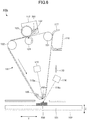
- FIG. 6 is a diagram illustrating an example configuration of the three-dimensional modeling apparatus 100b. As illustrated in FIG. 6 , the three-dimensional modeling apparatus 100b includes a fan 170 that is an example of an air blower.
- the fan 170 is configured to be operated when the modeling material 201 is caused to fly, and to blow air to the flown modeling material 201 in the direction opposite to the moving direction of the carrier 111. In this manner, the external force F is applied to the modeling material 201 by the power of the airflow. Accordingly, variations of the landing position of the modeling material 201 on the surface of the object can be reduced.
- the speed of airflow from the fan 170 is preferably the same as or is in a range of ⁇ 50% of the moving velocity of the carrier 111 such that variations in the flying direction of the modeling material 201 can be eliminated.
- the speed of airflow is set to 0.1 (m/s) that is the same as the moving velocity of the carrier 111.
- the three-dimensional modeling apparatus can fabricate a three-dimensional object without being affected by an electric discharge.
- the three-dimensional modeling apparatus 100c includes a supply device configured to stably supply the modeling material to a carrier.
- the supply device includes a conveyance carrier configured to carry and convey the modeling material stored in a material container, and a regulator configured to regulate the layer thickness of the modeling material carried by the conveyance carrier.
- FIG. 7 is a diagram illustrating an example configuration of the three-dimensional modeling apparatus 100c. As illustrated in FIG. 7 , the three-dimensional modeling apparatus 100c includes small-diameter rollers 158 and 159, a slit 103, and a supply device 300.
- the small-diameter rollers 158 and 159 are support members that support the carrier 111 by contacting the inner side of the carrier 111.
- the carrier 111 is stretched over the small-diameter rollers 158 and 159, and the small-diameter rollers 158 and 159 are driven to rotate in accordance with the circulation movement of the carrier 111.
- the small-diameter rollers 158 and 159 functioning as the support members that support the carrier 111 are provided. Accordingly, the carrier 111 can be circularly moved at high speed, and also an effect of preventing static electricity can be obtained.
- the small-diameter roller 158 is electrically connected to the grounded portion 156 (see FIG. 4 ), and the small-diameter roller 159 is connected to the power supply 157 (see FIG. 4 ).
- the three-dimensional modeling apparatus 100c causes the power supply 157 to apply a voltage so as to create an electric field between the small-diameter roller 158 and the small-diameter roller 159.
- the modeling material 201 carries minute electric charges during the conveyance of the modeling material 201. Therefore, an electrostatic force acting in a direction opposite to the moving direction of the carrier 111 can be applied to the modeling material 201. This electrostatic force causes the flown modeling material 201 to be moved in the direction opposite to the moving direction of the carrier 111, thereby reducing a landing position variation as indicated by d in FIG. 3C .
- the slit 103 is a member having an opening through which the laser light 116a emitted from the melting laser 116 passes.
- the object 200 is irradiated with the laser light 116a that has passed through the slit 103.
- the object 200 By causing the melting laser 116 to pass through the slit 103, the object 200 can be vertically irradiated with the laser light 116a while the heat dissipation of the object 200 is reduced. Further, it is preferable to provide an infrared camera having an optical system coaxial with the optical axis of the melting laser 116. With the above-described infrared camera, the melting state and the temperature of the object 200 being irradiated with the laser light 116a can be observed, and the fabrication can be controlled based on the observed conditions of the object 200.
- the supply device 300 includes a modeling material container 320, a carrying roller 301, a supplying roller 303, a doctor roller 310, and a scraper 311.
- the supply device 300 is configured to supply the modeling material 201 to the carrier 111.
- the modeling material container 320 is a container that stores the modeling material 201.
- the carrying roller 301 is an example of a conveyance carrier configured to carry, on the surface thereof, and convey the modeling material 201 stored in the modeling material container 320.
- the supplying roller 303 is rotatably provided in the modeling material container 320, and is configured to rotate to supply the modeling material 201 to the carrying roller 301.
- the doctor roller 310 is rotatably provided such that the surface of the doctor roller 310 is in proximity to the surface of the carrying roller 301.
- the doctor roller 310 is configured to regulate the thickness of the modeling material 201, carried on the surface of the carrying roller 301, while rotating.
- the doctor roller 310 is an example of a regulator.
- the scraper 311 is configured to clean the doctor roller 310 by scraping off the modeling material 201 remaining on the surface of the doctor roller 310 while contacting the surface of the doctor roller 310.
- the supply device 300 is disposed on the upstream side in the rotational direction of the carrying roller 301.
- the supplying roller 303 supplies the modeling material 201 to the carrying roller 301, and the doctor roller 310 regulates the thickness of the modeling material 201 on the surface of the carrying roller 301. In this manner, the supply device 300 can continuously and stably form a thin layer of the modeling material 201 on the surface of the carrying roller 301.
- the carrying roller 301 contacts the carrier 111 and transfers the thin layer of the modeling material 201 onto the surface of the carrier 111, thereby forming the thin layer of the modeling material 201 on the surface of the carrier 111.
- the thin layer of the modeling material 201 can firmly adhere to the surface of the carrier 111 when V111 ⁇ V301 is satisfied, where V111 denotes the conveying speed of the carrier 111 and V301 denotes the peripheral speed of the carrying roller 301.
- the configuration and the arrangement of the supply device 300 can be changed in accordance with the type of the modeling material 201 stored and held in the modeling material container 320.
- the material or the outer diameter of each of the carrying roller 301 and the supplying roller 303, the shape of the doctor roller 310, or the contact pressure or the contact position of the doctor roller 310 with respect to the carrying roller 301 can be changed.
- the supply device 300 can preliminarily store the above-described information in an information storage unit such as an IC chip, and the supply device 300 can acquire and change the information by referring to the information storage unit as necessary.
- the leveling blade can make the modeling material 201 uniform in a pre-step before the modeling material 201 is supplied and make the amount of the modeling material 201 uniform after the modeling material 201 passes through the supply device 300.
- the three-dimensional modeling method includes carrying a modeling material by a carrier, causing the modeling material carried by the carrier to fly to a surface of an object, and applying a predetermined external force to the flown modeling material. Accordingly, an effect similar to that of the three-dimensional modeling apparatus can be obtained by the three-dimensional modeling method.
Landscapes
- Engineering & Computer Science (AREA)
- Chemical & Material Sciences (AREA)
- Materials Engineering (AREA)
- Manufacturing & Machinery (AREA)
- Physics & Mathematics (AREA)
- Mechanical Engineering (AREA)
- Optics & Photonics (AREA)
Abstract
Description
- The disclosures herein relate to a three-dimensional modeling apparatus and a three-dimensional modeling method.
- As apparatuses for fabricating three-dimensional objects, additive manufacturing apparatuses utilizing techniques such as material extrusion (MEX), vat photopolymerization (VPP), powder bed fusion (PBF), material jetting (MJT), binder jetting (BJT), sheet lamination (SHL), and directed energy deposition (DED) are known.
- Further, there is known an apparatus configured to cause a three-dimensional modeling material that absorbs light to fly to an object by emitting an optical vortex laser beam to the modeling material, thereby causing the modeling material to adhere to the object (see Patent Document 1, for example).
- However, in the apparatus described in Patent Document 1, the flown modeling material is cured by ultraviolet irradiation after adhering to the object. Therefore, the modeling material may be dispersed when colliding with the object, and as a result, fabrication quality may be degraded.
- It is a general object of the present invention to improve fabrication quality.
- Patent Document 1: Re-publication of PCT International Publication No.
2016-136722 - According to at least one embodiment, a three-dimensional modeling apparatus includes a carrier configured to carry a modeling material, a device configured to cause the modeling material carried by the carrier to fly to the surface of an object, and an external force applying member configured to apply a predetermined external force to the modeling material when the modeling material is flying.
- According to the present invention, fabrication quality can be improved.
- Other objects and further features of the present invention will be apparent from the following detailed description when read in conjunction with the accompanying drawings, in which:
-
FIG. 1 is a diagram illustrating an example configuration of a three-dimensional modeling apparatus according to a first embodiment; -
FIG. 2 is a flowchart illustrating effects of the three-dimensional modeling apparatus according to the first embodiment; -
FIG. 3A is a diagram illustrating a deviation of the flying direction of a modeling material; -
FIG. 3B is a diagram illustrating a variation in the flying directions of modeling materials; -
FIG. 3C is a diagram illustrating an effect of reducing a variation in the flying directions of modeling materials; -
FIG. 4 is a diagram illustrating an example configuration of a fixing member; -
FIG. 5 is a diagram illustrating an example configuration of an electrically conductive member of a three-dimensional modeling apparatus according to a second embodiment; -
FIG. 6 is a diagram illustrating an example configuration of a three-dimensional modeling apparatus according to a third embodiment; and -
FIG. 7 is a diagram illustrating an example configuration of a three-dimensional modeling apparatus according to a fourth embodiment. - In the following, embodiments of the present invention will be described with reference to the accompanying drawings. In the drawings, the same elements are denoted by the same reference numerals, and a duplicate description thereof may be omitted.
- In the following embodiments, when a modeling material carried by a carrier is caused to fly to the surface of an object, a predetermined external force caused by an electric field, airflow, or gravity is applied to the flown modeling material. In this manner, variations in the landing position of the modeling material on the surface of the object due to inertia and variations in flying time can be reduced, thus improving fabrication quality.
- First, an apparatus for fabricating a three-dimensional object (hereinafter referred to as a "three-
dimensional modeling apparatus 100") according to a first embodiment will be described with reference toFIG. 1. FIG. 1 is a diagram illustrating an example configuration of the three-dimensional modeling apparatus 100. - As illustrated in
FIG. 1 , the three-dimensional modeling apparatus 100 includes astage 101, astage heater 102, acarrier 111, afixing member 155, asupply device 112, aflying laser 115, a meltinglaser 116 functioning to apply energy, acleaning blade 117, and acollecting case 118. - The
stage 101 is a support member that supports anobject 200 to be fabricated (an object in a fabrication process). Thestage 101 can move back and forth in directions indicated by an arrow Y, and can also move up and down in directions indicated by an arrow Z at a pitch of 0.05 mm (modeling thickness), for example. - The
stage heater 102 is disposed below thestage 101, and the temperature of thestage 101 is controlled to match the temperature of amodeling material 201. - The
carrier 111 is an endless belt that circularly moves. Specifically, thecarrier 111 is composed of a polyethylene terephthalate (PET) film (Lumirror, manufactured by Toray Industries, Inc.). Alternatively, thecarrier 111 may be composed of a polyimide film (Kapton H, manufactured by Toray Industries, Inc.). - The
carrier 111 is disposed above (on the upper side in the Z direction of) thestage 101, and is stretched overrollers fixing member 155. Thecarrier 111 carries theparticulate modeling material 201, and conveys themodeling material 201 to a position above theobject 200 on thestage 101. However, thecarrier 111 is not limited to the endless belt, and thecarrier 111 may be a rotary drum that is composed of a cylindrical glass member and rotates in a direction (conveying direction) indicated by an arrow while carrying themodeling material 201. - The
fixing member 155 is a support member that supports thecarrier 111, and is disposed above thestage 101 at a position (fabrication position) where theobject 200 is fabricated. A configuration and functions of thefixing member 155 will be described later in detail with reference toFIG. 4 . - The
modeling material 201 can be appropriately selected depending on theobject 200. For example, themodeling material 201 may be a resin, such as polyamide 12 (PA 12), polybutylene terephthalate (PBT), polysulfone (PSU), polyamide 66 (PA 66), polyethylene terephthalate (PET), liquid crystal polymer (LCP), polyether ether ketone (PEEK), polyacetal (POM), polysulfone (PSF), polyamide 6 (PA 6), or polyphenylene sulfide (PPS). Further, themodeling material 201 is not limited to a crystalline resin, and may be an amorphous resin such as polycarbonate (PC), acrylonitrile butadiene styrene (ABS), or polyetherimide (PEI). Alternatively, themodeling material 201 may be a mixture of a crystalline resin and an amorphous resin. - Alternatively, the
modeling material 201 may be any material other than a resin, such as metal, ceramic, or liquid. Further, themodeling material 201 may be a material having a viscosity greater than or equal to 1 Pascal-second (Pa·s). - In the present embodiment, the
modeling material 201 is carried on the peripheral surface of thecarrier 111 by the van der Waals force. If the resistance value of themodeling material 201 is high, themodeling material 201 can be carried only by electrostatic adhesion. - The
supply device 112 is disposed on thecarrier 111, and is configured to supply themodeling material 201 to the peripheral surface (front surface) of thecarrier 111. - The
supply device 112 includes aknurling roller 123 and ablade 122. In addition, acontact roller 124 having a rubber layer on the surface thereof is disposed facing theknurling roller 123. - The
supply device 112 grinds and rubs themodeling material 201 with theblade 122 to loosen the aggregation of themodeling material 201, and causes themodeling material 201 to pass through theknurling roller 123, such that a thin layer of themodeling material 201 is formed on the peripheral surface of thecarrier 111. - However, the configuration of the
supply device 112 is not limited to the above-described configuration using theknurling roller 123, and a configuration using a mesh roller may be used. Alternatively, a contact supply method or a non-contact supply method using a rotating body, a mesh-based non-contact spray method, or a fluidized bed coating method in which powder particles are dispersed by air may be used. - The flying
laser 115 functioning to cause themodeling material 201 to fly from the peripheral surface of thecarrier 111 is disposed inside thecarrier 111. - The flying
laser 115 is a pulsed laser, and irradiates themodeling material 201 withpulsed laser light 115a from the inside of the carrier 111 (the irradiation position corresponds to a "fabrication position"). The flyinglaser 115 is an example of a device configured to cause themodeling material 201 to fly. - By irradiating the
modeling material 201 with thepulsed laser light 115a, a force called radiation pressure is exerted on themodeling material 201, thereby causing the adhesion force of theparticulate modeling material 201 to be released. As a result, themodeling material 201 falls down by gravity. As is known, laser induced forward transfer (LIFT) as described inUS006025110A is a non-contact technique that transfers a film material or a liquid material from a carrier to a receiver surface by laser irradiation. The material is locally heated and vaporized, and as a result, the material flies from the peripheral surface of the carrier in the direction of laser irradiation. - As used herein, the term "fly" means that the
modeling material 201 is moved from thecarrier 111 to thestage 101 side in a non-contact manner. Because themodeling material 201 can be moved in a non-contact manner instead of being transferred, the loss of themodeling material 201 can be reduced and the fabrication accuracy can be improved. - In the example of
FIG. 1 , themodeling material 201 is caused to fly in the direction of gravity toward thestage 101. However, themodeling material 201 is not necessarily maintained at an angle of 90° with respect to the stage 10 when flying, and themodeling material 201 may be tilted at a desired angle with respect to the stage 10 when flying, as necessary. - In the present embodiment, it is not necessarily said that there is no contribution of the laser induced forward transfer technique. However, for the following reasons, the radiation pressure technique is mainly adopted.
- 1. The energy required to cause black powder, having a high absorption rate of laser light, to fly is equivalent to the energy required to cause transparent powder to fly.
- 2. The transparent powder flies even when the carrier is formed of a transparent resin film.
- 3. The transparent resin film forming the carrier is not degraded by being irradiated with pulsed laser light a plurality of times, up to 1000 times.
- The distance between the
carrier 111 and theobject 200 is preferably approximately 3 times to 4 times greater than the average particle diameter of themodeling material 201. In this manner, the contact between an upper-side particle and a lower-side particle before and after being flown can be avoided. Thus, the dispersion of themodeling material 201 due to flying can be avoided. - Further, the
melting laser 116 functioning to heat the surface of theobject 200 is disposed outside of thecarrier 111. As themelting laser 116, a pulsed laser is not required to be actively used, and a continuous-wave laser is suitable. - The
melting laser 116 heats and melts the surface of theobject 200 to be fabricated on thestage 101, such that the surface of theobject 200 is in a melted state. - As described, the
melting laser 116 heats and melts the surface of theobject 200, such that the surface of theobject 200 is in a melted state. However, as long as the surface of theobject 200 is melted by the energy of one or more energy sources, convection, a lamp, inductive heating, dielectric heating, and the like may be applied instead of laser heating. Further, the "surface" may include one layer that is formed at once, or may include a plurality of layers such as two or three layers. Alternatively, the "surface" may include a part of or the entirety of each layer. That is, it is important for the "surface" to include a part of the outermost layer. - In
FIG. 1 ,laser light 116a, emitted from themelting laser 116, is directed at the irradiation position of thepulsed laser light 115a (the landing position of the modeling material 201). The irradiation positions of thelaser light 116a and thepulsed laser light 115a can be adjusted, and may be changed in accordance with the type of the material and the fabrication speed. - Accordingly, the
modeling material 201, caused to fly by the irradiation of thelaser light 116a, lands on the surface of theobject 200 melted by thelaser light 116a emitted from themelting laser 116. As a result, themodeling material 201 adheres to theobject 200. - The relationship between the timing at which the
modeling material 201 flies and the timing at which theobject 200 starts to be melted is not particularly limited. That is, the surface of theobject 200 may be melted before themodeling material 201 flies. Alternatively, the surface of theobject 200 may be melted after themodeling material 201 flies. Further, after themodeling material 201 flies, the surface of theobject 200 may be melted, and themodeling material 201 may land on the melted surface of theobject 200. - Variations in landing positions and inappropriate landing positions can be adjusted for each layer. The shape of an object is not determined by the flying
laser 115 and is determined by themelting laser 116. - Further, the
carrier 111 includes thecleaning blade 117 that removes themodeling material 201 remaining on thecarrier 111. Thecleaning blade 117 is disposed on the downstream side in the rotational direction of thecarrier 111. Themodeling material 201 removed by thecleaning blade 117 is collected in the collectingcase 118. - Next, effects of the three-
dimensional modeling apparatus 100 will be described with reference to a flowchart ofFIG. 2 . - When the three-
dimensional modeling apparatus 100 starts a fabrication process, thesupply device 112 grinds and rubs amodeling material 201 stored in thesupply device 112 with the blade 122 (step S1, hereinafter simply referred to as "S1"). Themodeling material 201 is conveyed by the knurling roller 123 (S2), and themodeling material 201 is supplied onto the peripheral surface of thecarrier 111 such that portions of themodeling material 201 do not overlap (S3). Thesupply device 112 continues to supply themodeling material 201 onto thecarrier 111 until the fabrication is completed. - In this manner, the
supply device 112 supplies themodeling material 201 onto the peripheral surface of thecarrier 111. Themodeling material 201 is carried on the surface of thecarrier 111 disposed above thestage 101 that supports anobject 200. - The
modeling material 201 is conveyed to a position above thestage 101 by the rotation of thecarrier 111, and a ceiling of themodeling material 201 is formed above thestage 101. - In the meantime, at a timing at which the fabrication is started (S5), the
melting laser 116 emits thelaser light 116a to heat and melt a part of the surface of theobject 200 to which themodeling material 201 adheres (S6). Note that a first layer forming theobject 200 is fused because of the temperature of thestage heater 102. - The flying
laser 115 irradiates themodeling material 201 with thepulsed laser light 115a based on fabrication data, thereby causing themodeling material 201 carried by thecarrier 111 to fly from thecarrier 111 to the melted part of the object 200 (S7). - The
modeling material 201 flown from thecarrier 111 lands on the melted part of the surface of theobject 200, and is integrated with theobject 200. That is, theobject 200 is grown by an amount corresponding to the integrated modeling material. - Accordingly, while sequentially conveying the
modeling material 201 by the continuous rotation of thecarrier 111 to a position above thestage 101, the three-dimensional modeling apparatus 100 repeats the fabrication process for causing themelting laser 116 to melt the surface of theobject 200, and causing the flyinglaser 115 to irradiate themodeling material 201 such that themodeling material 201 flies and lands on theobject 200, until the fabrication is completed (S8). - In this manner, a three-dimensional object can be fabricated by growing the
object 200 to a desired shape. - The
modeling material 201, flown from thecarrier 111, lands on and adheres to the melted surface of theobject 200. Therefore, themodeling material 201 is not dispersed due to collision with theobject 200. Accordingly, even edges of theobject 200 can be highly accurately formed, thus improving fabrication quality. - Further, the
modeling material 201 is not limited to a crystalline resin, and a mixture of a crystalline resin and an amorphous resin can be used as themodeling material 201. Therefore, a variety of materials can be utilized. Further, the fabrication speed can be increased by continuous fabrication, and waste materials can be reduced. - Next, the flying direction of the
modeling material 201 will be described with reference toFIGS. 3A through 3C. FIG. 3A is a diagram illustrating a deviation of the flying direction of amodeling material 201a due to inertia,FIG. 3B is a diagram illustrating a variation in the flying directions ofmodeling materials FIG. 3C is a diagram illustrating an effect of reducing a variation in the flying directions ofmodeling materials - In each of the examples illustrated in
FIGS. 3A through 3C , while thecarrier 111 is circularly moving at a moving velocity V1, a modeling material carried by thecarrier 111 is irradiated with thepulsed laser light 115a, and the modeling material flies toward the surface of theobject 200. The direction indicated by anarrow 30 is the moving direction of thecarrier 111 and is an example of a "predetermined direction". - In
FIG. 3A , themodeling material 201a flies towards the surface of theobject 200 at an initial velocity V2 in the direction of gravity g. At this time, the force of inertia of the movingcarrier 111 acts on themodeling material 201a. Thus, themodeling material 201a flies at an initial velocity V3 also in the moving direction indicated by thearrow 30. - As a result of summing the initial velocities V2 and V3, the
modeling material 201a flies in a direction indicated by anarrow 31 deviated from the direction of gravity g, which is a target direction of themodeling material 201a. Note that amodeling material 201a' represents a modeling material that has flown in the direction indicated by thearrow 31 inFIG. 3A . - For example, when it is assumed that the moving velocity V1 of the
modeling material 201a is 100 (mm/s) and the flying time of themodeling material 201 is 0.02 (s), themodeling material 201a lands on the surface of theobject 200 at a position deviated by "100 . 0.02 = 2 (mm)" in the moving direction with respect to the direction of gravity g. - Further, the flying time of the
modeling material 201 may vary. Example factors of variations in flying time include variations in the initial velocity of modeling materials at the time of laser irradiation, variations in air resistance due to the difference in particle sizes of modeling materials, an effect caused by the collision of modeling materials, and an effect caused by the rotation of a modeling material. - In the upper part of
FIG. 3B , an initial velocity V21 indicates an initial velocity component of themodeling material 201b in the direction of gravity g. As a result of summing the initial velocity V21 in the direction of gravity g and the initial velocity V3 in the moving direction, themodeling material 201b flies in a direction indicated by anarrow 311. In the lower part ofFIG. 3B , an initial velocity V22 indicates an initial velocity component of themodeling material 201c in the direction of gravity g, and the initial velocity V22 is greater than the above-described initial velocity V21. As a result of summing the initial velocity V22 in the direction of gravity g and the initial velocity V3 in the moving direction, themodeling material 201c flies in a direction indicated by anarrow 312. The direction indicated by thearrow 312 is close to the direction of gravity g as compared to the direction indicated by thearrow 311. - As a result of the above-described variation in the flying directions of the
modeling materials modeling materials object 200 would vary by a distance d. Such a variation would degrade the fabrication quality of the three-dimensional modeling apparatus 100. - Conversely, in the present embodiment, as illustrated in
FIG. 3C , an external force F in a direction opposite to the moving direction of thecarrier 111 is applied to flownmodeling materials modeling materials - The external force F causes the flown
modeling materials carrier 111, thereby reducing a variation in the landing positions of themodeling materials object 200. In addition, the longer the flying time of a modeling material is, the greater the amount of movement of the modeling material by the external force F becomes. Further, the shorter the flying time of a modeling material is, the smaller the amount of movement of the modeling material by the external force F becomes. As a result, a variation in the landing positions of themodeling materials object 200 can be reduced. - Next, a configuration of the fixing
member 155 will be described with reference toFIG. 4. FIG. 4 is a diagram illustrating an example configuration of the fixingmember 155. - As illustrated in
FIG. 4 , the fixingmember 155 is a member having a half-ring shape, and aslit portion 155a is formed in a part of the fixingmember 155. In the three-dimensional modeling apparatus 100, the fixingmember 155 is disposed facing theobject 200 with thecarrier 111 being interposed between the fixingmember 155 and theobject 200. Thepulsed laser light 115a of the flying laser 11 passes through theslit portion 155a and is emitted to thecarrier 111. - The fixing
member 155 is composed of a conductor such as stainless steel (SUS) metal, and is electrically conductive while ensuring wear resistance against contact with thecarrier 111 that is stretched over the periphery of the fixingmember 155. - The
slit portion 155a of the fixingmember 155 is composed of an insulator, such as glass, that is transparent to thepulsed laser light 115a. The fixingmember 155 is separated into oneend portion 155b and theother end portion 155c by theslit portion 155a composed of the insulator. Therefore, the oneend portion 155b is insulated from theother end portion 155c with theslit portion 155a being interposed therebetween. - Further, because the
slit portion 155a is transparent to thepulsed laser light 115a, thepulsed laser light 115a can pass through theslit portion 155a and can be emitted to themodeling material 201 carried by thecarrier 111. The fixingmember 155 is an example of an "external force applying member" configured to apply the external force F, and is also configured to support thecarrier 111. - Note that the
slit portion 155a is not necessarily composed of the insulator, and may be an opening. With this configuration, thepulsed laser light 115a can pass through theslit portion 155a, and the oneend portion 155b can be insulated from theother end portion 155c. - The one
end portion 155b is connected to a groundedportion 156, and theother end portion 155c of the fixingmember 155 is electrically connected to apower supply 157. When the flyinglaser 115 emits thepulsed laser light 115a, thepower supply 157 applies a voltage, thereby creating an electric field in theslit portion 155a. - Typically, the
modeling material 201 carries minute electric charges during the conveyance of themodeling material 201. By utilizing the electric charges, an electrostatic force in the direction opposite to the moving direction of thecarrier 111 can be applied to themodeling material 201. This electrostatic force causes the flownmodeling material 201 to be moved in the direction opposite to the moving direction of thecarrier 111, thereby reducing the variation in the landing position of themodeling material 201. - Further, in the present embodiment, PA 12 is used as the
modeling material 201, and themodeling material 201 is positively charged. Accordingly, an electric field in the downstream direction is created on the surface of thecarrier 111 by arranging the groundedportion 156 on the upstream side in the moving direction of thecarrier 111 and thepower supply 157 for applying a voltage on the downstream side. Therefore, the electrostatic force in the direction opposite to the moving direction of thecarrier 111 can be applied to themodeling material 201. - The
modeling material 201 may be negatively charged depending on the type of themodeling material 201. In such a case, the groundedportion 156 and thepower supply 157 illustrated inFIG. 4 may be arranged reversely. Further, a switch or any other device may be utilized to switch the arrangement of thepower supply 157 and the groundedportion 156 depending on the type of themodeling material 201. In this manner, the external force F caused by the electrostatic force can be appropriately applied in accordance with the type of themodeling material 201. - In the present embodiment, the
modeling material 201 is not specifically charged in an active manner. However, themodeling material 201 may be triboelectrically charged in an active manner by mixing themodeling material 201 with another powder material and stirring the mixture, or by causing themodeling material 201 to pass through a nip between rotating members, as in the case of a toner for electrophotography. Accordingly, the external force F caused by the electrostatic force can be appropriately applied to themodeling material 201. - Next, more detailed conditions for generating the external force F will be described.
- It is assumed that a
modeling material 201a takes time t (s) to land on the surface of theobject 200 after flying, and amodeling material 201b takes time t + Δt (s) to land on the surface of theobject 200 after flying. When the moving velocity of thecarrier 111 is assumed to be V1 (m/s), a variation in the landing positions of themodeling material 201a and themodeling material 201b can be expressed by the following formula (1).
- When a voltage E (V) is assumed to be applied to the
slit portion 155a having a width w (m), an electric field is represented by E/w (N/C). Further, when the amount of electric charge per unit mass of themodeling material 201 is assumed to be Q (C/kg), the acceleration applied to themodeling material 201 is represented by E · Q/w (m/s2). - Accordingly, the correction amount of the variation in the landing positions of the
modeling material 201a and themodeling material 201b can be expressed by the following formula (2).
- A voltage for correcting the variation in the landing positions is represented by V · Δt = E · Q · t · Δt/w, that is E = V1 . w / (Q . t).
- The following are examples of estimated values for generating the external force according to the present embodiment.
- Modeling material 201: PA 12
- Amount of electric charge Q: 0.3 (mC/kg)
- Moving velocity V1: 0.1 (m/s)
- Width w: 0.0015 (m)
- Time t: 0.02 (s)
- Voltage E: 26 (V)
- There may be cases where an error occurs in the above-described estimated values due to an electric field that is not uniformly formed in the horizontal direction, a variation in air resistance due to the difference in particle sizes of modeling materials, an effect caused by the rotation of a modeling material, or the like. Therefore, it is preferable to adjust the conditions for generating the external force in a range of approximately ±50% of the estimated values.
- As described above, in the present embodiment, when the
modeling material 201 carried by thecarrier 111 is caused to fly to the surface of theobject 200, the external force F generated by an electric field is applied to themodeling material 201. The external force F acts in the direction opposite to the moving direction of thecarrier 111. Further, the electric field is created by applying a voltage to the fixingmember 155. - By applying the external force F to the flown
modeling material 201, themodeling material 201 is moved in the direction opposite to the moving direction of thecarrier 111. Accordingly, variations in the landing position of themodeling material 201 on the surface of theobject 200 can be reduced. Further, as the flying time of themodeling material 201 increases, the amount of movement of themodeling material 201 by the external force F increases. Further, as the flying time of themodeling material 201 decreases, the amount of movement of themodeling material 201 by the external force F decreases. As a result, variations in the landing position of themodeling material 201 can be reduced. - As described above, variations in the landing position of the
modeling material 201 on the surface of theobject 200 caused by inertia and variations in flying time can be reduced, thereby improving fabrication quality. - Further, in the present embodiment, the fixing
member 155 functioning to support thecarrier 111 is used to apply a voltage to thecarrier 111, thereby applying the external force F to the flownmodeling material 201. That is, thecarrier 111 can also function to apply the external force F. Thus, the external force F can be applied to the flownmodeling material 201 without any additional configuration for applying the external force F. - Next, a three-
dimensional modeling apparatus 100a according to a second embodiment will be described.FIG. 5 is a diagram illustrating an example configuration of an electricallyconductive member 160 of the three-dimensional modeling apparatus 100a. InFIG. 5 , anarrow 30 indicates the moving direction of thecarrier 111, and anarrow 32 indicates the scanning direction of thepulsed laser light 115a. - As illustrated in
FIG. 5 , the electricallyconductive member 160 includes awire 160a and awire 160b, and is disposed in a space between thecarrier 111 and theobject 200. Thewire 160a and thewire 160b, constituting the electricallyconductive member 160, are spaced apart from each other in a direction along the moving direction of thecarrier 111, such that thepulsed laser light 115a passes between thewire 160a and thewire 160b. - Each of the
wires wires pulsed laser light 115a. - Further, the
wire 160a disposed on the upstream side in the moving direction of thecarrier 111 is electrically connected to a groundedportion 161, and thewire 160b disposed on the downstream side is connected to apower supply 162. Thepower supply 162 applies a voltage to thewire 160a, thereby creating an electric field in the space between thewire 160a and thewire 160b. Accordingly, an electrostatic force generated by the electric field can be applied to the flownmodeling material 201 as the external force F. - When the
modeling material 201 carried by thecarrier 111 is irradiated with thepulsed laser light 115a and flies to the surface of theobject 200, the flownmodeling material 201 is moved by the external force F in the direction opposite to the moving direction of thecarrier 111. Accordingly, variations in the landing position of themodeling material 201 on the surface of theobject 200 can be reduced. - An electric field can be directly controlled by the electrically
conductive member 160 including thewires member 155. Therefore, variations in the landing position of themodeling material 201 can be more preferably reduced. A method for setting the voltage applied to the electricallyconductive member 160 and the arrangement of thewires - Next, a three-
dimensional modeling apparatus 100b according to a third embodiment will be described. In the present embodiment, an external force is applied to a flown modeling material by supplying air to the flown modeling material. In this manner, variations in the landing position of the modeling material on the surface of the object can be reduced. -
FIG. 6 is a diagram illustrating an example configuration of the three-dimensional modeling apparatus 100b. As illustrated inFIG. 6 , the three-dimensional modeling apparatus 100b includes afan 170 that is an example of an air blower. - The
fan 170 is configured to be operated when themodeling material 201 is caused to fly, and to blow air to the flownmodeling material 201 in the direction opposite to the moving direction of thecarrier 111. In this manner, the external force F is applied to themodeling material 201 by the power of the airflow. Accordingly, variations of the landing position of themodeling material 201 on the surface of the object can be reduced. - The speed of airflow from the
fan 170 is preferably the same as or is in a range of ±50% of the moving velocity of thecarrier 111 such that variations in the flying direction of themodeling material 201 can be eliminated. In the present embodiment, the speed of airflow is set to 0.1 (m/s) that is the same as the moving velocity of thecarrier 111. - When the external force F is applied by the electrostatic force generated by an electric field, there may be cases where the operation of the three-dimensional modeling apparatus may be affected by an electric discharge. However, in the present embodiment, because the external force F is caused by the power of the airflow, the three-dimensional modeling apparatus can fabricate a three-dimensional object without being affected by an electric discharge.
- However, there may be cases where natural convection may affect the operation of the three-dimensional modeling apparatus. Therefore, it is preferable to take into account the state of airflow. In addition, in order to stabilize airflow, it is preferable to constantly generate ionic wind by a capacitor instead of the fan.
- Next, a three-
dimensional modeling apparatus 100c according to a fourth embodiment will be described. In the present embodiment, an electrostatic force is used to apply an external force to a modeling material that has flown. Accordingly, variations in the landing position of the modeling material on the surface of the object can be reduced. Further, the three-dimensional modeling apparatus 100c includes a supply device configured to stably supply the modeling material to a carrier. The supply device includes a conveyance carrier configured to carry and convey the modeling material stored in a material container, and a regulator configured to regulate the layer thickness of the modeling material carried by the conveyance carrier. -
FIG. 7 is a diagram illustrating an example configuration of the three-dimensional modeling apparatus 100c. As illustrated inFIG. 7 , the three-dimensional modeling apparatus 100c includes small-diameter rollers slit 103, and asupply device 300. - The small-
diameter rollers carrier 111 by contacting the inner side of thecarrier 111. Thecarrier 111 is stretched over the small-diameter rollers diameter rollers carrier 111. - Instead of the fixing member 155 (see
FIG. 1 ) according to the first embodiment, the small-diameter rollers carrier 111 are provided. Accordingly, thecarrier 111 can be circularly moved at high speed, and also an effect of preventing static electricity can be obtained. - Further, the small-
diameter roller 158 is electrically connected to the grounded portion 156 (seeFIG. 4 ), and the small-diameter roller 159 is connected to the power supply 157 (seeFIG. 4 ). When thepulsed laser light 115a is emitted from the flyinglaser 115 to thecarrier 111, the three-dimensional modeling apparatus 100c causes thepower supply 157 to apply a voltage so as to create an electric field between the small-diameter roller 158 and the small-diameter roller 159. - Typically, the
modeling material 201 carries minute electric charges during the conveyance of themodeling material 201. Therefore, an electrostatic force acting in a direction opposite to the moving direction of thecarrier 111 can be applied to themodeling material 201. This electrostatic force causes the flownmodeling material 201 to be moved in the direction opposite to the moving direction of thecarrier 111, thereby reducing a landing position variation as indicated by d inFIG. 3C . - The
slit 103 is a member having an opening through which thelaser light 116a emitted from themelting laser 116 passes. In the three-dimensional modeling apparatus 100c, theobject 200 is irradiated with thelaser light 116a that has passed through theslit 103. - By causing the
melting laser 116 to pass through theslit 103, theobject 200 can be vertically irradiated with thelaser light 116a while the heat dissipation of theobject 200 is reduced. Further, it is preferable to provide an infrared camera having an optical system coaxial with the optical axis of themelting laser 116. With the above-described infrared camera, the melting state and the temperature of theobject 200 being irradiated with thelaser light 116a can be observed, and the fabrication can be controlled based on the observed conditions of theobject 200. - The
supply device 300 includes amodeling material container 320, a carryingroller 301, a supplyingroller 303, adoctor roller 310, and ascraper 311. Thesupply device 300 is configured to supply themodeling material 201 to thecarrier 111. - The
modeling material container 320 is a container that stores themodeling material 201. The carryingroller 301 is an example of a conveyance carrier configured to carry, on the surface thereof, and convey themodeling material 201 stored in themodeling material container 320. - The supplying
roller 303 is rotatably provided in themodeling material container 320, and is configured to rotate to supply themodeling material 201 to the carryingroller 301. Thedoctor roller 310 is rotatably provided such that the surface of thedoctor roller 310 is in proximity to the surface of the carryingroller 301. Thedoctor roller 310 is configured to regulate the thickness of themodeling material 201, carried on the surface of the carryingroller 301, while rotating. Thedoctor roller 310 is an example of a regulator. - The
scraper 311 is configured to clean thedoctor roller 310 by scraping off themodeling material 201 remaining on the surface of thedoctor roller 310 while contacting the surface of thedoctor roller 310. - In the three-
dimensional modeling apparatus 100c, thesupply device 300 is disposed on the upstream side in the rotational direction of the carryingroller 301. The supplyingroller 303 supplies themodeling material 201 to the carryingroller 301, and thedoctor roller 310 regulates the thickness of themodeling material 201 on the surface of the carryingroller 301. In this manner, thesupply device 300 can continuously and stably form a thin layer of themodeling material 201 on the surface of the carryingroller 301. - The carrying
roller 301 contacts thecarrier 111 and transfers the thin layer of themodeling material 201 onto the surface of thecarrier 111, thereby forming the thin layer of themodeling material 201 on the surface of thecarrier 111. - The thin layer of the
modeling material 201 can firmly adhere to the surface of thecarrier 111 when V111 < V301 is satisfied, where V111 denotes the conveying speed of thecarrier 111 and V301 denotes the peripheral speed of the carryingroller 301. - Further, the configuration and the arrangement of the
supply device 300 can be changed in accordance with the type of themodeling material 201 stored and held in themodeling material container 320. For example, the material or the outer diameter of each of the carryingroller 301 and the supplyingroller 303, the shape of thedoctor roller 310, or the contact pressure or the contact position of thedoctor roller 310 with respect to the carryingroller 301 can be changed. Thesupply device 300 can preliminarily store the above-described information in an information storage unit such as an IC chip, and thesupply device 300 can acquire and change the information by referring to the information storage unit as necessary. - Further, it is preferable to dispose a leveling blade on the upstream side of the
supply device 300. The leveling blade can make themodeling material 201 uniform in a pre-step before themodeling material 201 is supplied and make the amount of themodeling material 201 uniform after themodeling material 201 passes through thesupply device 300. - Further, although the embodiments of the present invention have been described in detail above, the present invention is not limited to the particulars of the above-described embodiments, and variations and modifications may be made to the above-described embodiments without departing from the scope of the present invention.
- Further, a three-dimensional modeling method according to an embodiment of the present invention is also provided. For example, the three-dimensional modeling method includes carrying a modeling material by a carrier, causing the modeling material carried by the carrier to fly to a surface of an object, and applying a predetermined external force to the flown modeling material. Accordingly, an effect similar to that of the three-dimensional modeling apparatus can be obtained by the three-dimensional modeling method.
-
- 100
- three-dimensional modeling apparatus
- 101
- stage
- 102
- stage heater
- 111
- carrier
- 115
- flying laser
- 115a
- pulsed laser light
- 116
- melting laser (functioning to apply energy)
- 116a
- laser light (energy)
- 117
- cleaning blade
- 118
- collecting case
- 122
- blade
- 123
- knurling roller
- 124
- contact roller
- 151, 152
- roller
- 155
- fixing member
- 155a
- slit portion
- 156
- grounded portion
- 157
- power supply
- 160
- electrically conductive member
- 160a, 160b
- wire
- 161
- grounded portion
- 162
- power supply
- 170
- fan
- 200
- object
- 201
- material
- 30
- arrow (moving direction)
- 31
- arrow (flying direction)
- 32
- arrow (scanning direction)
- g
- gravity
- d
- distance varied
- 103
- slit
- 158, 59
- small-diameter roller
- 300
- supply device
- 301
- carrying roller (example of conveyance carrier)
- 303
- supplying roller (example of supply member)
- 310
- doctor roller (example of regulator)
- 311
- scraper
- V1
- moving velocity
- V2
- initial velocity in direction of gravity
- V3
- initial velocity in moving direction
Claims (8)
- A three-dimensional modeling apparatus comprising:a carrier configured to carry a modeling material;a device configured to cause the modeling material carried by the carrier to fly to a surface of an object; andan external force applying member configured to apply a predetermined external force to the modeling material when the modeling material is flying.
- The three-dimensional modeling apparatus according to claim 1, wherein the carrier moves in a predetermined direction, and the predetermined external force acts in a direction opposite to the predetermined direction.
- The three-dimensional modeling apparatus according to claim 1 or 2, wherein the external force applying member applies the predetermined external force by applying a voltage to the carrier.
- The three-dimensional modeling apparatus according to any one of claims 1 to 3, wherein the external force applying member is further configured to support the carrier.
- The three-dimensional modeling apparatus according to any one of claims 1 to 4, further comprising an electrically conductive member between the carrier and the object,
wherein the external force applying member applies the predetermined external force by applying a voltage to the electrically conductive member. - The three-dimensional modeling apparatus according to any one of claims 1 to 5, further comprising an air blower configured to blow air to the flown modeling material.
- The three-dimensional modeling apparatus according to any one of claims 1 to 6, further comprising a supply device configured to supply the modeling material to the carrier,
wherein the supply device includesa material container configured to store the modeling material,a conveyance carrier configured to carry and convey the modeling material stored in the material container, anda regulator configured to regulate a layer thickness of the modeling material carried by the conveyance carrier. - A three-dimensional modeling method comprising:carrying a modeling material by a carrier;causing the modeling material carried by the carrier to fly to a surface of an object; andapplying a predetermined external force to the modeling material when the modeling material is flying.
Applications Claiming Priority (2)
| Application Number | Priority Date | Filing Date | Title |
|---|---|---|---|
| JP2020026565 | 2020-02-19 | ||
| JP2020182382A JP7547937B2 (en) | 2020-02-19 | 2020-10-30 | 3D printing device, 3D printing method |
Publications (2)
| Publication Number | Publication Date |
|---|---|
| EP3868544A1 true EP3868544A1 (en) | 2021-08-25 |
| EP3868544B1 EP3868544B1 (en) | 2023-08-23 |
Family
ID=74550500
Family Applications (1)
| Application Number | Title | Priority Date | Filing Date |
|---|---|---|---|
| EP21154947.2A Active EP3868544B1 (en) | 2020-02-19 | 2021-02-03 | Three-dimensional modeling apparatus and three-dimensional modeling method |
Country Status (2)
| Country | Link |
|---|---|
| US (1) | US11958242B2 (en) |
| EP (1) | EP3868544B1 (en) |
Families Citing this family (2)
| Publication number | Priority date | Publication date | Assignee | Title |
|---|---|---|---|---|
| US11779955B1 (en) * | 2022-03-04 | 2023-10-10 | Reophotonics, Ltd. | Methods for residual material collection in laser-assisted deposition |
| EP4519064A1 (en) * | 2022-05-05 | 2025-03-12 | Paxis LLC | Additive manufacturing apparatus, system, and method |
Citations (6)
| Publication number | Priority date | Publication date | Assignee | Title |
|---|---|---|---|---|
| US5935462A (en) * | 1994-10-24 | 1999-08-10 | Matsushita Electric Industrial Co., Ltd. | Repair of metal lines by electrostatically assisted laser ablative deposition |
| US6025110A (en) | 1997-09-18 | 2000-02-15 | Nowak; Michael T. | Method and apparatus for generating three-dimensional objects using ablation transfer |
| WO2016136722A1 (en) | 2015-02-25 | 2016-09-01 | 株式会社リコー | Light-absorbing material jetting device, light-absorbing material jetting method, and applications using same |
| US20170216918A1 (en) * | 2016-02-02 | 2017-08-03 | Melissa E. Orme-Marmarelis | Methods and systems for fabrication using multi-material and precision alloy droplet jetting |
| US20180015502A1 (en) * | 2016-07-17 | 2018-01-18 | Io Tech Group Ltd. | Kit and system for laser-induced material dispensing |
| CN107962770A (en) * | 2017-12-18 | 2018-04-27 | 中国科学院沈阳自动化研究所 | A kind of biological 3D printing system based on Coulter principle |
Family Cites Families (8)
| Publication number | Priority date | Publication date | Assignee | Title |
|---|---|---|---|---|
| DE10306886A1 (en) * | 2003-02-18 | 2004-09-02 | Daimlerchrysler Ag | Three dimensional object manufacture comprises forming adhesive coated particle layers on top of one another, subjecting each layer to ionizing particles before activating adhesive and smoothing with a blade |
| JP6613659B2 (en) | 2014-12-18 | 2019-12-04 | 株式会社リコー | Solid modeling object and manufacturing method thereof |
| JP6732466B2 (en) * | 2016-02-15 | 2020-07-29 | キヤノン株式会社 | Modeling apparatus and modeling method |
| EP3276430B1 (en) * | 2016-07-25 | 2019-09-04 | Ricoh Company, Ltd. | Image forming apparatus |
| JP6922653B2 (en) | 2017-10-27 | 2021-08-18 | 株式会社リコー | Modeling method and modeling system |
| JP2019077935A (en) | 2017-10-27 | 2019-05-23 | キヤノン株式会社 | Three-dimensional molding device and method for manufacturing three-dimensional molded object |
| JP7264651B2 (en) | 2019-01-23 | 2023-04-25 | エス.ラボ株式会社 | Printing apparatus, system, printing method and program |
| JP7287124B2 (en) | 2019-06-03 | 2023-06-06 | 株式会社リコー | Apparatus for flying light-absorbing material, apparatus for forming three-dimensional object, method for flying light-absorbing material |
-
2021
- 2021-01-28 US US17/160,549 patent/US11958242B2/en active Active
- 2021-02-03 EP EP21154947.2A patent/EP3868544B1/en active Active
Patent Citations (6)
| Publication number | Priority date | Publication date | Assignee | Title |
|---|---|---|---|---|
| US5935462A (en) * | 1994-10-24 | 1999-08-10 | Matsushita Electric Industrial Co., Ltd. | Repair of metal lines by electrostatically assisted laser ablative deposition |
| US6025110A (en) | 1997-09-18 | 2000-02-15 | Nowak; Michael T. | Method and apparatus for generating three-dimensional objects using ablation transfer |
| WO2016136722A1 (en) | 2015-02-25 | 2016-09-01 | 株式会社リコー | Light-absorbing material jetting device, light-absorbing material jetting method, and applications using same |
| US20170216918A1 (en) * | 2016-02-02 | 2017-08-03 | Melissa E. Orme-Marmarelis | Methods and systems for fabrication using multi-material and precision alloy droplet jetting |
| US20180015502A1 (en) * | 2016-07-17 | 2018-01-18 | Io Tech Group Ltd. | Kit and system for laser-induced material dispensing |
| CN107962770A (en) * | 2017-12-18 | 2018-04-27 | 中国科学院沈阳自动化研究所 | A kind of biological 3D printing system based on Coulter principle |
Also Published As
| Publication number | Publication date |
|---|---|
| EP3868544B1 (en) | 2023-08-23 |
| US11958242B2 (en) | 2024-04-16 |
| US20210252782A1 (en) | 2021-08-19 |
Similar Documents
| Publication | Publication Date | Title |
|---|---|---|
| EP3868544B1 (en) | Three-dimensional modeling apparatus and three-dimensional modeling method | |
| JP3845593B2 (en) | Classification device, developing device, image forming apparatus, classification method, developing method, and image forming method | |
| KR101774462B1 (en) | Semi-crystalline consumable materials for electrophotography-based additive manufacturing system | |
| US5124749A (en) | Damping electrode wires of a developer unit | |
| JP7424093B2 (en) | Devices for printing 3D objects, methods for printing 3D objects | |
| EP0534671B1 (en) | Phenolic graphite donor roll | |
| US20030054107A1 (en) | Coating die with laser position sensors | |
| JP7547937B2 (en) | 3D printing device, 3D printing method | |
| US8660471B2 (en) | Developer supply device and image forming apparatus having the same | |
| US6175707B1 (en) | Integrated toner transport/toner charging device | |
| JP2005148739A (en) | Metal and ceramic mixed donor roll coating | |
| JP4687457B2 (en) | Developer transport device and image forming apparatus | |
| US5132735A (en) | Development apparatus with toner diverting members | |
| US8644742B2 (en) | Developer supply device and image forming apparatus having the same | |
| US20040258435A1 (en) | Hybrid electrophotographic development with toner induction charged via AC induced conductivity | |
| JP2001139144A (en) | Powder transfer device and image forming device | |
| US20150078787A1 (en) | Developing device and an image forming apparatus including the same | |
| JPH04232979A (en) | Nonrestrictive unit-component developing apparatus | |
| JP6372083B2 (en) | Wiring pattern forming apparatus, wiring pattern forming method, and wiring board | |
| JPH10104933A (en) | Printer for generating image by use of toner grain | |
| US6088562A (en) | Electrode wire grid for developer unit | |
| US11203150B2 (en) | Layer orientation in selective deposition based additive manufacturing of parts | |
| CN1261963A (en) | single component one developer | |
| JP6540629B2 (en) | Image forming device | |
| JP5609186B2 (en) | Toner carrier, developing device, and image forming apparatus |
Legal Events
| Date | Code | Title | Description |
|---|---|---|---|
| PUAI | Public reference made under article 153(3) epc to a published international application that has entered the european phase |
Free format text: ORIGINAL CODE: 0009012 |
|
| STAA | Information on the status of an ep patent application or granted ep patent |
Free format text: STATUS: REQUEST FOR EXAMINATION WAS MADE |
|
| 17P | Request for examination filed |
Effective date: 20210203 |
|
| AK | Designated contracting states |
Kind code of ref document: A1 Designated state(s): AL AT BE BG CH CY CZ DE DK EE ES FI FR GB GR HR HU IE IS IT LI LT LU LV MC MK MT NL NO PL PT RO RS SE SI SK SM TR |
|
| GRAP | Despatch of communication of intention to grant a patent |
Free format text: ORIGINAL CODE: EPIDOSNIGR1 |
|
| STAA | Information on the status of an ep patent application or granted ep patent |
Free format text: STATUS: GRANT OF PATENT IS INTENDED |
|
| RIC1 | Information provided on ipc code assigned before grant |
Ipc: B22F 12/50 20210101ALI20230219BHEP Ipc: B22F 12/57 20210101ALI20230219BHEP Ipc: B22F 12/00 20210101ALI20230219BHEP Ipc: B22F 10/25 20210101ALI20230219BHEP Ipc: B29C 64/153 20170101ALI20230219BHEP Ipc: B29C 64/194 20170101ALI20230219BHEP Ipc: B29C 64/223 20170101ALI20230219BHEP Ipc: B29C 64/232 20170101ALI20230219BHEP Ipc: B29C 64/236 20170101ALI20230219BHEP Ipc: B29C 64/241 20170101ALI20230219BHEP Ipc: B29C 64/295 20170101ALI20230219BHEP Ipc: B33Y 10/00 20150101ALI20230219BHEP Ipc: B33Y 30/00 20150101ALI20230219BHEP Ipc: B22F 10/00 20210101ALI20230219BHEP Ipc: B29C 64/124 20170101AFI20230219BHEP |
|
| INTG | Intention to grant announced |
Effective date: 20230317 |
|
| P01 | Opt-out of the competence of the unified patent court (upc) registered |
Effective date: 20230427 |
|
| GRAS | Grant fee paid |
Free format text: ORIGINAL CODE: EPIDOSNIGR3 |
|
| GRAA | (expected) grant |
Free format text: ORIGINAL CODE: 0009210 |
|
| STAA | Information on the status of an ep patent application or granted ep patent |
Free format text: STATUS: THE PATENT HAS BEEN GRANTED |
|
| AK | Designated contracting states |
Kind code of ref document: B1 Designated state(s): AL AT BE BG CH CY CZ DE DK EE ES FI FR GB GR HR HU IE IS IT LI LT LU LV MC MK MT NL NO PL PT RO RS SE SI SK SM TR |
|
| REG | Reference to a national code |
Ref country code: GB Ref legal event code: FG4D |
|
| REG | Reference to a national code |
Ref country code: CH Ref legal event code: EP |
|
| REG | Reference to a national code |
Ref country code: DE Ref legal event code: R096 Ref document number: 602021004385 Country of ref document: DE |
|
| REG | Reference to a national code |
Ref country code: IE Ref legal event code: FG4D |
|
| REG | Reference to a national code |
Ref country code: LT Ref legal event code: MG9D |
|
| REG | Reference to a national code |
Ref country code: NL Ref legal event code: MP Effective date: 20230823 |
|
| REG | Reference to a national code |
Ref country code: AT Ref legal event code: MK05 Ref document number: 1602088 Country of ref document: AT Kind code of ref document: T Effective date: 20230823 |
|
| PG25 | Lapsed in a contracting state [announced via postgrant information from national office to epo] |
Ref country code: GR Free format text: LAPSE BECAUSE OF FAILURE TO SUBMIT A TRANSLATION OF THE DESCRIPTION OR TO PAY THE FEE WITHIN THE PRESCRIBED TIME-LIMIT Effective date: 20231124 |
|
| PG25 | Lapsed in a contracting state [announced via postgrant information from national office to epo] |
Ref country code: IS Free format text: LAPSE BECAUSE OF FAILURE TO SUBMIT A TRANSLATION OF THE DESCRIPTION OR TO PAY THE FEE WITHIN THE PRESCRIBED TIME-LIMIT Effective date: 20231223 |
|
| PG25 | Lapsed in a contracting state [announced via postgrant information from national office to epo] |
Ref country code: SE Free format text: LAPSE BECAUSE OF FAILURE TO SUBMIT A TRANSLATION OF THE DESCRIPTION OR TO PAY THE FEE WITHIN THE PRESCRIBED TIME-LIMIT Effective date: 20230823 Ref country code: RS Free format text: LAPSE BECAUSE OF FAILURE TO SUBMIT A TRANSLATION OF THE DESCRIPTION OR TO PAY THE FEE WITHIN THE PRESCRIBED TIME-LIMIT Effective date: 20230823 Ref country code: PT Free format text: LAPSE BECAUSE OF FAILURE TO SUBMIT A TRANSLATION OF THE DESCRIPTION OR TO PAY THE FEE WITHIN THE PRESCRIBED TIME-LIMIT Effective date: 20231226 Ref country code: NO Free format text: LAPSE BECAUSE OF FAILURE TO SUBMIT A TRANSLATION OF THE DESCRIPTION OR TO PAY THE FEE WITHIN THE PRESCRIBED TIME-LIMIT Effective date: 20231123 Ref country code: NL Free format text: LAPSE BECAUSE OF FAILURE TO SUBMIT A TRANSLATION OF THE DESCRIPTION OR TO PAY THE FEE WITHIN THE PRESCRIBED TIME-LIMIT Effective date: 20230823 Ref country code: LV Free format text: LAPSE BECAUSE OF FAILURE TO SUBMIT A TRANSLATION OF THE DESCRIPTION OR TO PAY THE FEE WITHIN THE PRESCRIBED TIME-LIMIT Effective date: 20230823 Ref country code: LT Free format text: LAPSE BECAUSE OF FAILURE TO SUBMIT A TRANSLATION OF THE DESCRIPTION OR TO PAY THE FEE WITHIN THE PRESCRIBED TIME-LIMIT Effective date: 20230823 Ref country code: IS Free format text: LAPSE BECAUSE OF FAILURE TO SUBMIT A TRANSLATION OF THE DESCRIPTION OR TO PAY THE FEE WITHIN THE PRESCRIBED TIME-LIMIT Effective date: 20231223 Ref country code: HR Free format text: LAPSE BECAUSE OF FAILURE TO SUBMIT A TRANSLATION OF THE DESCRIPTION OR TO PAY THE FEE WITHIN THE PRESCRIBED TIME-LIMIT Effective date: 20230823 Ref country code: GR Free format text: LAPSE BECAUSE OF FAILURE TO SUBMIT A TRANSLATION OF THE DESCRIPTION OR TO PAY THE FEE WITHIN THE PRESCRIBED TIME-LIMIT Effective date: 20231124 Ref country code: FI Free format text: LAPSE BECAUSE OF FAILURE TO SUBMIT A TRANSLATION OF THE DESCRIPTION OR TO PAY THE FEE WITHIN THE PRESCRIBED TIME-LIMIT Effective date: 20230823 Ref country code: AT Free format text: LAPSE BECAUSE OF FAILURE TO SUBMIT A TRANSLATION OF THE DESCRIPTION OR TO PAY THE FEE WITHIN THE PRESCRIBED TIME-LIMIT Effective date: 20230823 |
|
| PG25 | Lapsed in a contracting state [announced via postgrant information from national office to epo] |
Ref country code: PL Free format text: LAPSE BECAUSE OF FAILURE TO SUBMIT A TRANSLATION OF THE DESCRIPTION OR TO PAY THE FEE WITHIN THE PRESCRIBED TIME-LIMIT Effective date: 20230823 |
|
| PG25 | Lapsed in a contracting state [announced via postgrant information from national office to epo] |
Ref country code: ES Free format text: LAPSE BECAUSE OF FAILURE TO SUBMIT A TRANSLATION OF THE DESCRIPTION OR TO PAY THE FEE WITHIN THE PRESCRIBED TIME-LIMIT Effective date: 20230823 |
|
| PG25 | Lapsed in a contracting state [announced via postgrant information from national office to epo] |
Ref country code: SM Free format text: LAPSE BECAUSE OF FAILURE TO SUBMIT A TRANSLATION OF THE DESCRIPTION OR TO PAY THE FEE WITHIN THE PRESCRIBED TIME-LIMIT Effective date: 20230823 Ref country code: RO Free format text: LAPSE BECAUSE OF FAILURE TO SUBMIT A TRANSLATION OF THE DESCRIPTION OR TO PAY THE FEE WITHIN THE PRESCRIBED TIME-LIMIT Effective date: 20230823 Ref country code: ES Free format text: LAPSE BECAUSE OF FAILURE TO SUBMIT A TRANSLATION OF THE DESCRIPTION OR TO PAY THE FEE WITHIN THE PRESCRIBED TIME-LIMIT Effective date: 20230823 Ref country code: EE Free format text: LAPSE BECAUSE OF FAILURE TO SUBMIT A TRANSLATION OF THE DESCRIPTION OR TO PAY THE FEE WITHIN THE PRESCRIBED TIME-LIMIT Effective date: 20230823 Ref country code: DK Free format text: LAPSE BECAUSE OF FAILURE TO SUBMIT A TRANSLATION OF THE DESCRIPTION OR TO PAY THE FEE WITHIN THE PRESCRIBED TIME-LIMIT Effective date: 20230823 Ref country code: CZ Free format text: LAPSE BECAUSE OF FAILURE TO SUBMIT A TRANSLATION OF THE DESCRIPTION OR TO PAY THE FEE WITHIN THE PRESCRIBED TIME-LIMIT Effective date: 20230823 Ref country code: SK Free format text: LAPSE BECAUSE OF FAILURE TO SUBMIT A TRANSLATION OF THE DESCRIPTION OR TO PAY THE FEE WITHIN THE PRESCRIBED TIME-LIMIT Effective date: 20230823 |
|
| REG | Reference to a national code |
Ref country code: DE Ref legal event code: R097 Ref document number: 602021004385 Country of ref document: DE |
|
| PG25 | Lapsed in a contracting state [announced via postgrant information from national office to epo] |
Ref country code: IT Free format text: LAPSE BECAUSE OF FAILURE TO SUBMIT A TRANSLATION OF THE DESCRIPTION OR TO PAY THE FEE WITHIN THE PRESCRIBED TIME-LIMIT Effective date: 20230823 |
|
| PLBE | No opposition filed within time limit |
Free format text: ORIGINAL CODE: 0009261 |
|
| STAA | Information on the status of an ep patent application or granted ep patent |
Free format text: STATUS: NO OPPOSITION FILED WITHIN TIME LIMIT |
|
| 26N | No opposition filed |
Effective date: 20240524 |
|
| PG25 | Lapsed in a contracting state [announced via postgrant information from national office to epo] |
Ref country code: SI Free format text: LAPSE BECAUSE OF FAILURE TO SUBMIT A TRANSLATION OF THE DESCRIPTION OR TO PAY THE FEE WITHIN THE PRESCRIBED TIME-LIMIT Effective date: 20230823 |
|
| PG25 | Lapsed in a contracting state [announced via postgrant information from national office to epo] |
Ref country code: MC Free format text: LAPSE BECAUSE OF FAILURE TO SUBMIT A TRANSLATION OF THE DESCRIPTION OR TO PAY THE FEE WITHIN THE PRESCRIBED TIME-LIMIT Effective date: 20230823 |
|
| REG | Reference to a national code |
Ref country code: CH Ref legal event code: PL |
|
| PG25 | Lapsed in a contracting state [announced via postgrant information from national office to epo] |
Ref country code: LU Free format text: LAPSE BECAUSE OF NON-PAYMENT OF DUE FEES Effective date: 20240203 |
|
| PG25 | Lapsed in a contracting state [announced via postgrant information from national office to epo] |
Ref country code: CH Free format text: LAPSE BECAUSE OF NON-PAYMENT OF DUE FEES Effective date: 20240229 |
|
| PG25 | Lapsed in a contracting state [announced via postgrant information from national office to epo] |
Ref country code: LU Free format text: LAPSE BECAUSE OF NON-PAYMENT OF DUE FEES Effective date: 20240203 Ref country code: CH Free format text: LAPSE BECAUSE OF NON-PAYMENT OF DUE FEES Effective date: 20240229 |
|
| PG25 | Lapsed in a contracting state [announced via postgrant information from national office to epo] |
Ref country code: BG Free format text: LAPSE BECAUSE OF FAILURE TO SUBMIT A TRANSLATION OF THE DESCRIPTION OR TO PAY THE FEE WITHIN THE PRESCRIBED TIME-LIMIT Effective date: 20230823 |
|
| PG25 | Lapsed in a contracting state [announced via postgrant information from national office to epo] |
Ref country code: BG Free format text: LAPSE BECAUSE OF FAILURE TO SUBMIT A TRANSLATION OF THE DESCRIPTION OR TO PAY THE FEE WITHIN THE PRESCRIBED TIME-LIMIT Effective date: 20230823 |
|
| REG | Reference to a national code |
Ref country code: BE Ref legal event code: MM Effective date: 20240229 |
|
| PG25 | Lapsed in a contracting state [announced via postgrant information from national office to epo] |
Ref country code: BE Free format text: LAPSE BECAUSE OF NON-PAYMENT OF DUE FEES Effective date: 20240229 |
|
| PG25 | Lapsed in a contracting state [announced via postgrant information from national office to epo] |
Ref country code: IE Free format text: LAPSE BECAUSE OF NON-PAYMENT OF DUE FEES Effective date: 20240203 |
|
| PG25 | Lapsed in a contracting state [announced via postgrant information from national office to epo] |
Ref country code: IE Free format text: LAPSE BECAUSE OF NON-PAYMENT OF DUE FEES Effective date: 20240203 Ref country code: BE Free format text: LAPSE BECAUSE OF NON-PAYMENT OF DUE FEES Effective date: 20240229 |
|
| PG25 | Lapsed in a contracting state [announced via postgrant information from national office to epo] |
Ref country code: CY Free format text: LAPSE BECAUSE OF FAILURE TO SUBMIT A TRANSLATION OF THE DESCRIPTION OR TO PAY THE FEE WITHIN THE PRESCRIBED TIME-LIMIT; INVALID AB INITIO Effective date: 20210203 |
|
| PG25 | Lapsed in a contracting state [announced via postgrant information from national office to epo] |
Ref country code: HU Free format text: LAPSE BECAUSE OF FAILURE TO SUBMIT A TRANSLATION OF THE DESCRIPTION OR TO PAY THE FEE WITHIN THE PRESCRIBED TIME-LIMIT; INVALID AB INITIO Effective date: 20210203 |
|
| PG25 | Lapsed in a contracting state [announced via postgrant information from national office to epo] |
Ref country code: TR Free format text: LAPSE BECAUSE OF FAILURE TO SUBMIT A TRANSLATION OF THE DESCRIPTION OR TO PAY THE FEE WITHIN THE PRESCRIBED TIME-LIMIT Effective date: 20230823 |
|
| PGFP | Annual fee paid to national office [announced via postgrant information from national office to epo] |
Ref country code: GB Payment date: 20260220 Year of fee payment: 6 |
|
| PGFP | Annual fee paid to national office [announced via postgrant information from national office to epo] |
Ref country code: DE Payment date: 20260218 Year of fee payment: 6 |
|
| PGFP | Annual fee paid to national office [announced via postgrant information from national office to epo] |
Ref country code: FR Payment date: 20260218 Year of fee payment: 6 |