WO2016136722A1 - Light-absorbing material jetting device, light-absorbing material jetting method, and applications using same - Google Patents
Light-absorbing material jetting device, light-absorbing material jetting method, and applications using same Download PDFInfo
- Publication number
- WO2016136722A1 WO2016136722A1 PCT/JP2016/055208 JP2016055208W WO2016136722A1 WO 2016136722 A1 WO2016136722 A1 WO 2016136722A1 JP 2016055208 W JP2016055208 W JP 2016055208W WO 2016136722 A1 WO2016136722 A1 WO 2016136722A1
- Authority
- WO
- WIPO (PCT)
- Prior art keywords
- absorbing material
- light absorbing
- light
- flying
- laser beam
- Prior art date
Links
Images


Classifications
-
- B—PERFORMING OPERATIONS; TRANSPORTING
- B28—WORKING CEMENT, CLAY, OR STONE
- B28B—SHAPING CLAY OR OTHER CERAMIC COMPOSITIONS; SHAPING SLAG; SHAPING MIXTURES CONTAINING CEMENTITIOUS MATERIAL, e.g. PLASTER
- B28B1/00—Producing shaped prefabricated articles from the material
- B28B1/001—Rapid manufacturing of 3D objects by additive depositing, agglomerating or laminating of material
-
- B—PERFORMING OPERATIONS; TRANSPORTING
- B29—WORKING OF PLASTICS; WORKING OF SUBSTANCES IN A PLASTIC STATE IN GENERAL
- B29C—SHAPING OR JOINING OF PLASTICS; SHAPING OF MATERIAL IN A PLASTIC STATE, NOT OTHERWISE PROVIDED FOR; AFTER-TREATMENT OF THE SHAPED PRODUCTS, e.g. REPAIRING
- B29C64/00—Additive manufacturing, i.e. manufacturing of three-dimensional [3D] objects by additive deposition, additive agglomeration or additive layering, e.g. by 3D printing, stereolithography or selective laser sintering
-
- B—PERFORMING OPERATIONS; TRANSPORTING
- B29—WORKING OF PLASTICS; WORKING OF SUBSTANCES IN A PLASTIC STATE IN GENERAL
- B29C—SHAPING OR JOINING OF PLASTICS; SHAPING OF MATERIAL IN A PLASTIC STATE, NOT OTHERWISE PROVIDED FOR; AFTER-TREATMENT OF THE SHAPED PRODUCTS, e.g. REPAIRING
- B29C67/00—Shaping techniques not covered by groups B29C39/00 - B29C65/00, B29C70/00 or B29C73/00
-
- B—PERFORMING OPERATIONS; TRANSPORTING
- B33—ADDITIVE MANUFACTURING TECHNOLOGY
- B33Y—ADDITIVE MANUFACTURING, i.e. MANUFACTURING OF THREE-DIMENSIONAL [3-D] OBJECTS BY ADDITIVE DEPOSITION, ADDITIVE AGGLOMERATION OR ADDITIVE LAYERING, e.g. BY 3-D PRINTING, STEREOLITHOGRAPHY OR SELECTIVE LASER SINTERING
- B33Y10/00—Processes of additive manufacturing
-
- B—PERFORMING OPERATIONS; TRANSPORTING
- B33—ADDITIVE MANUFACTURING TECHNOLOGY
- B33Y—ADDITIVE MANUFACTURING, i.e. MANUFACTURING OF THREE-DIMENSIONAL [3-D] OBJECTS BY ADDITIVE DEPOSITION, ADDITIVE AGGLOMERATION OR ADDITIVE LAYERING, e.g. BY 3-D PRINTING, STEREOLITHOGRAPHY OR SELECTIVE LASER SINTERING
- B33Y30/00—Apparatus for additive manufacturing; Details thereof or accessories therefor
-
- B—PERFORMING OPERATIONS; TRANSPORTING
- B41—PRINTING; LINING MACHINES; TYPEWRITERS; STAMPS
- B41J—TYPEWRITERS; SELECTIVE PRINTING MECHANISMS, i.e. MECHANISMS PRINTING OTHERWISE THAN FROM A FORME; CORRECTION OF TYPOGRAPHICAL ERRORS
- B41J2/00—Typewriters or selective printing mechanisms characterised by the printing or marking process for which they are designed
- B41J2/005—Typewriters or selective printing mechanisms characterised by the printing or marking process for which they are designed characterised by bringing liquid or particles selectively into contact with a printing material
- B41J2/01—Ink jet
- B41J2/015—Ink jet characterised by the jet generation process
- B41J2/04—Ink jet characterised by the jet generation process generating single droplets or particles on demand
-
- B—PERFORMING OPERATIONS; TRANSPORTING
- B41—PRINTING; LINING MACHINES; TYPEWRITERS; STAMPS
- B41J—TYPEWRITERS; SELECTIVE PRINTING MECHANISMS, i.e. MECHANISMS PRINTING OTHERWISE THAN FROM A FORME; CORRECTION OF TYPOGRAPHICAL ERRORS
- B41J2/00—Typewriters or selective printing mechanisms characterised by the printing or marking process for which they are designed
- B41J2/005—Typewriters or selective printing mechanisms characterised by the printing or marking process for which they are designed characterised by bringing liquid or particles selectively into contact with a printing material
- B41J2/01—Ink jet
- B41J2/135—Nozzles
- B41J2/14—Structure thereof only for on-demand ink jet heads
- B41J2/14016—Structure of bubble jet print heads
- B41J2/14088—Structure of heating means
- B41J2/14104—Laser or electron beam heating the ink
-
- B—PERFORMING OPERATIONS; TRANSPORTING
- B41—PRINTING; LINING MACHINES; TYPEWRITERS; STAMPS
- B41M—PRINTING, DUPLICATING, MARKING, OR COPYING PROCESSES; COLOUR PRINTING
- B41M5/00—Duplicating or marking methods; Sheet materials for use therein
- B41M5/26—Thermography ; Marking by high energetic means, e.g. laser otherwise than by burning, and characterised by the material used
- B41M5/382—Contact thermal transfer or sublimation processes
-
- G—PHYSICS
- G02—OPTICS
- G02B—OPTICAL ELEMENTS, SYSTEMS OR APPARATUS
- G02B5/00—Optical elements other than lenses
- G02B5/003—Light absorbing elements
-
- G—PHYSICS
- G03—PHOTOGRAPHY; CINEMATOGRAPHY; ANALOGOUS TECHNIQUES USING WAVES OTHER THAN OPTICAL WAVES; ELECTROGRAPHY; HOLOGRAPHY
- G03G—ELECTROGRAPHY; ELECTROPHOTOGRAPHY; MAGNETOGRAPHY
- G03G15/00—Apparatus for electrographic processes using a charge pattern
- G03G15/22—Apparatus for electrographic processes using a charge pattern involving the combination of more than one step according to groups G03G13/02 - G03G13/20
- G03G15/221—Machines other than electrographic copiers, e.g. electrophotographic cameras, electrostatic typewriters
- G03G15/224—Machines for forming tactile or three dimensional images by electrographic means, e.g. braille, 3d printing
-
- B—PERFORMING OPERATIONS; TRANSPORTING
- B41—PRINTING; LINING MACHINES; TYPEWRITERS; STAMPS
- B41M—PRINTING, DUPLICATING, MARKING, OR COPYING PROCESSES; COLOUR PRINTING
- B41M2205/00—Printing methods or features related to printing methods; Location or type of the layers
- B41M2205/08—Ablative thermal transfer, i.e. the exposed transfer medium is propelled from the donor to a receptor by generation of a gas
Definitions
- the present invention relates to a light-absorbing material flying device, an image forming apparatus, and a three-dimensional shaped object manufacturing apparatus, and a light absorbing material flying method, an image forming method, and a three-dimensional shaped object manufacturing method.
- various image forming apparatuses including an ink jet recording system and an electrophotographic system have been developed.
- various image forming apparatuses have been developed and commercialized using an ink jet recording system that can be reduced in price, reduced in running cost, and downsized, and has excellent quietness.
- an image forming apparatus having a large nozzle diameter for reducing the flow path resistance of the ink has been proposed (for example, patents).
- Reference 1 an image forming apparatus having means for supporting the high-viscosity ink in the form of ink droplets on the surface of a flat ink carrier, and heating and flying a part of the ink carrier based on image information has been proposed (see, for example, Patent Document 2).
- the light absorber flying device of the present invention as a means for solving the problems includes a light absorber that absorbs light and an optical vortex laser beam corresponding to the light absorption wavelength of the light absorber.
- Light absorbing material flying means for irradiating and causing the light absorbing material to fly in the irradiation direction of the optical vortex laser beam by the energy of the optical vortex laser beam and to adhere to the adherend.
- a light absorbing material flying device capable of flying the light absorbing material having a particularly high viscosity among light absorbing materials that absorb light and attaching the light absorbing material to an adherend in a shape in which scattering is suppressed. be able to.
- FIG. 1A is a schematic diagram showing a wavefront (equal phase plane) in a general laser beam.
- FIG. 1B is a diagram showing a light intensity distribution in a general laser beam.
- FIG. 1C is a diagram showing a phase distribution in a general laser beam.
- FIG. 2A is a schematic diagram showing a wavefront (equal phase plane) in an optical vortex laser beam.
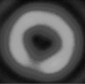
- FIG. 2B is a diagram showing a light intensity distribution in the optical vortex laser beam.
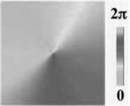
- FIG. 2C is a diagram showing a phase distribution in the optical vortex laser beam.
- FIG. 3A is a diagram illustrating an example of a result of interference measurement in an optical vortex laser beam.
- FIG. 3A is a diagram illustrating an example of a result of interference measurement in an optical vortex laser beam.
- FIG. 3B is a diagram illustrating an example of a result of interference measurement in a laser beam having a point with a light intensity of 0 at the center.
- FIG. 4A is a schematic cross-sectional view showing an example of the light absorbing material flying device of the present invention.
- FIG. 4B is a schematic cross-sectional view showing another example of the light absorbing material flying device of the present invention.
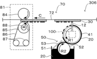
- FIG. 5A is a schematic cross-sectional view showing an example of the light absorbing material flying device shown in FIG. 4B to which a light absorbing material supply unit and an adherend transporting unit are added.
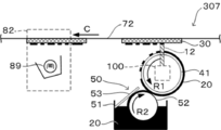
- FIG. 5B is a schematic cross-sectional view showing another example of the light absorbing material flying device shown in FIG.
- FIG. 5C is a schematic cross-sectional view showing another example of the light absorbing material flying device shown in FIG. 4B to which the light absorbing material supply means and the adherend conveying means are added.
- 6A is a schematic cross-sectional view showing an example of the light absorbing material flying device shown in FIG. 5A to which a fixing unit is added.
- FIG. 6B is a schematic cross-sectional view showing another example of the light absorber flying device shown in FIG. 5A to which fixing means is added.
- FIG. 6C is a schematic cross-sectional view showing another example of the light absorber flying device shown in FIG. 5A to which fixing means is added.
- FIG. 5A is a schematic cross-sectional view showing an example of the light absorber flying device shown in FIG. 5A to which fixing means is added.
- FIG. 7A is a schematic sectional view showing an example of the image forming apparatus of the present invention.
- FIG. 7B is a schematic cross-sectional view showing another example of the image forming apparatus of the present invention.
- FIG. 8 is a schematic cross-sectional view showing an example of a manufacturing apparatus for a three-dimensional structure of the present invention.
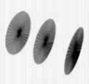
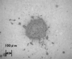
- FIG. 9A is a photograph showing the adhering state of the light absorbing material that is made to fly by the optical vortex laser beam of the light absorbing material flying device of the present invention.
- FIG. 9B is a photograph showing the adhering state of the light absorbing material that is made to fly by the optical vortex laser beam of the light absorbing material flying device of the present invention.
- FIG. 9A is a photograph showing the adhering state of the light absorbing material that is made to fly by the optical vortex laser beam of the light absorbing material flying device of the present invention.
- FIG. 9B is a photograph showing the adhering state of the light absorbing material that is made
- FIG. 9C is a photograph showing the adhering state of the light absorbing material that is made to fly by the optical vortex laser beam of the light absorbing material flying device of the present invention.
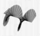
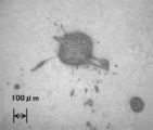
- FIG. 10A is a photograph showing the state of adhesion of the light absorbing material that is made to fly by a laser beam.
- FIG. 10B is a photograph showing the attached state of the light absorbing material that has been made to fly by the laser beam.
- FIG. 10C is a photograph showing the state of adhesion of the light absorbing material that is made to fly by the laser beam.
- FIG. 11 is a schematic diagram showing an example of a method for observing the flight state of the light absorbing material that is caused to fly by the optical vortex laser beam of the light absorbing material flying device of the present invention.
- FIG. 11 is a schematic diagram showing an example of a method for observing the flight state of the light absorbing material that is caused to fly by the optical vortex laser beam of the light absorbing material flying device of the present invention.
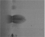
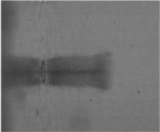
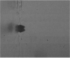
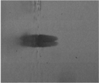
- FIG. 12A is a photograph showing a flying state of the light absorbing material that is caused to fly by the optical vortex laser beam of the light absorbing material flying device of the present invention.
- FIG. 12B is a photograph showing the flying state of the light absorbing material that is caused to fly by the optical vortex laser beam of the light absorbing material flying device of the present invention.
- FIG. 12C is a photograph showing a flying state of the light absorbing material that is caused to fly by the optical vortex laser beam of the light absorbing material flying device of the present invention.
- FIG. 13A is a photograph showing a flying state of the light absorbing material that is caused to fly by the optical vortex laser beam of the light absorbing material flying device of the present invention.
- FIG. 13B is a photograph showing a flying state of the light absorbing material that is caused to fly by the optical vortex laser beam of the light absorbing material flying device of the present invention.
- FIG. 13C is a photograph showing a flying state of the light absorbing material that is caused to fly by the optical vortex laser beam of the light absorbing material flying device of the present invention.
- FIG. 14A is a photograph showing a flying state of the light absorbing material that is caused to fly by the optical vortex laser beam of the light absorbing material flying device of the present invention.
- FIG. 14B is a photograph showing a flying state of the light absorbing material that is caused to fly by the optical vortex laser beam of the light absorbing material flying device of the present invention.
- FIG. 14A is a photograph showing a flying state of the light absorbing material that is caused to fly by the optical vortex laser beam of the light absorbing material flying device of the present invention.
- FIG. 14B is a photograph showing a flying state of the light absorbing material that is caused to fly
- FIG. 14C is a photograph showing the flying state of the light absorbing material that is caused to fly by the optical vortex laser beam of the light absorbing material flying device of the present invention.
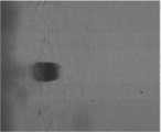
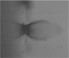
- FIG. 15A is a photograph showing a flying state of a light absorbing material that has been caused to fly by a laser beam.
- FIG. 15B is a photograph showing the flying state of the light absorbing material that has been caused to fly by the laser beam.
- FIG. 15C is a photograph showing the flying state of the light absorbing material that has been caused to fly by the laser beam.
- the light absorbing material flying device of the present invention irradiates the light absorbing material with a light absorbing material that absorbs light and an optical vortex laser beam corresponding to the light absorption wavelength of the light absorbing material, and energy of the optical vortex laser beam And a light absorbing material flying means for causing the light absorbing material to fly in the irradiation direction of the optical vortex laser beam and to adhere to the adherend, and further includes other means as necessary.
- the light absorbing material flying method of the present invention the light absorbing material that absorbs light is irradiated with an optical vortex laser beam corresponding to the light absorption wavelength of the light absorbing material, and the light absorbing material is generated by energy of the optical vortex laser beam In the irradiation direction of the optical vortex laser beam, and a light absorbing material flying step for adhering to the adherend, and further including other steps as necessary.
- the light absorbing material flying method can be preferably performed by the light absorbing material flying device, the light absorbing material flying step can be suitably performed by the light absorbing material flying means, and the other steps are: It can be performed by the other means.
- the nozzle diameter must be increased as the viscosity of the ink increases, and the nozzle diameter This is based on the knowledge that the diameter of the ejected ink droplet becomes relatively large when the value of is increased, so that the resolution is lowered.
- the light absorbing material flying device and the light absorbing material flying method of the present invention are the image forming apparatus described in Patent Document 2, in which the dot diameter formed on the recording medium due to the change in the gap between the ink carrier and the recording medium. This is based on the knowledge that there is a case where there is a variation in the color and an image in which the ink is scattered.
- the light absorbing material flying device and the light absorbing material flying method of the present invention are difficult to adhere the ink having high viscosity to the recording medium in a stable shape in the field of image formation in the conventional inkjet recording method.
- it is based on the knowledge that it is difficult to attach diversifying materials in a stable shape.
- a general laser beam Since a general laser beam has the same phase, it has a planar equiphase surface (wavefront) as shown in FIG. 1A. Since the direction of the pointing vector of the laser beam is an orthogonal direction of the planar equiphase surface, when the laser beam is applied to the light absorbing material, the light absorbing material is irradiated in the irradiation direction. Force acts. However, since the light intensity distribution in the cross section of the laser beam is a normal distribution (Gaussian distribution) having the strongest beam center as shown in FIG. 1B, the light absorbing material is likely to be scattered. Further, when the phase distribution is observed, it is confirmed that there is no phase difference as shown in FIG. 1C.
- the optical vortex laser beam has the helical equiphase surface as shown in FIG. 2A. Since the direction of the pointing vector of the optical vortex laser beam is orthogonal to the helical equiphase surface, when the optical vortex laser beam is applied to the light absorbing material, force is applied in the orthogonal direction. Act. For this reason, as shown in FIG. 2B, the light intensity distribution becomes a concave donut-shaped distribution in which the center of the beam becomes zero, and the light absorber irradiated with the optical vortex laser beam radiates donut-shaped energy.
- a method for determining whether or not the optical vortex laser beam is used is not particularly limited and may be appropriately selected depending on the purpose. Examples thereof include the above-described observation of phase distribution and interference measurement. Is common.
- the interference measurement can be observed using a laser beam profiler (such as a laser beam profiler manufactured by Spiricon, a laser beam profiler manufactured by Hamamatsu Photonics), and examples of the results of the interference measurement are shown in FIGS. 3A and 3B.
- FIG. 3A is an explanatory diagram showing an example of the result of interference measurement in an optical vortex laser beam
- FIG. 3B is an explanatory diagram showing an example of the result of interference measurement in a laser beam having a point with a light intensity of 0 at the center.
- the optical vortex laser beam is interferometrically measured, as shown in FIG. 3A, it can be confirmed that the energy distribution has a donut shape and has a light intensity of 0 at the center as in FIG. 1C.
- interference measurement of a general laser beam having a point with a light intensity of 0 at the center is similar to the optical vortex laser beam interference measurement shown in FIG. 3A as shown in FIG. Since the energy distribution of the part is not uniform, the difference from the optical vortex laser beam can be confirmed.
- the light absorbing material flying step the light absorbing material that absorbs light is irradiated with the optical vortex laser beam corresponding to the light absorption wavelength of the light absorbing material, and the energy of the optical vortex laser beam is irradiated.
- a step of causing the light absorbing material to fly in the irradiation direction and adhere to the adherend and can be suitably performed using, for example, the light absorbing material flying means.
- the light absorbing material flying means irradiates the light absorbing material with the light eddy laser beam corresponding to the light absorption wavelength of the light absorbing material onto the light absorbing material that absorbs light, and energy of the optical vortex laser beam.
- the light absorbing material flying means may irradiate the light absorbing material carried on the surface of the light absorbing material carrier capable of transmitting the light with an optical vortex laser beam from the back surface of the light absorbing material carrier. preferable. For example, as shown in FIG.
- the flying state when the optical vortex laser beam is applied to the optical absorber is an optical vortex laser with respect to the optical absorber 20 supported on the surface of the optical absorber support 40.
- the beam 12 is irradiated from the back surface of the light absorbing material carrier 40, and the state can be observed by photographing with a high-speed camera 140 in one frame 100ns.
- the high-speed camera include a high-speed video camera HyperVision HPV-X manufactured by Shimadzu Corporation.
- the said light absorption material flight means has a laser light source and an optical vortex conversion part, and also has another member as needed.
- the laser light source is not particularly limited as long as the laser beam can be generated, and can be appropriately selected according to the purpose.
- Examples thereof include a solid-state laser, a gas laser, and a semiconductor laser, and those capable of pulse oscillation are preferable.
- Examples of the solid-state laser include a YAG laser and a titanium sapphire laser.
- Examples of the gas laser include an argon laser, a helium neon laser, and a carbon dioxide gas laser.
- the semiconductor laser having an output of about 30 mW is preferable from the viewpoint of downsizing and cost reduction of the apparatus.
- a titanium sapphire laser was experimentally used.
- the laser light source may be a laser light source capable of outputting the optical vortex laser beam.
- the optical vortex converter is not particularly limited as long as the laser beam can be converted into the optical vortex laser beam, and can be appropriately selected according to the purpose.
- a diffractive optical element for example, a diffractive optical element, a multimode fiber, a liquid crystal phase modulator Etc.
- the diffractive optical element include a helical phase plate and a hologram element. Among these, a helical phase plate is preferable.
- the method of generating the optical vortex laser beam is not limited to the method of using the optical vortex conversion unit, the method of oscillating the optical vortex from the laser resonator as an eigenmode, the method of inserting a hologram element into the resonator, Examples include a method using excitation light converted into a donut beam, a method using a resonator mirror having a dark spot, and a method of oscillating an optical vortex mode using a thermal lens effect generated by a side-pumped solid-state laser as a spatial filter.
- a quarter wavelength plate is disposed in the optical path downstream from the optical vortex converter, and the linearly polarized optical vortex laser beam is It is preferable to set the optical axis of the four-wave plate at an angle of + 45 ° to convert it into circularly polarized light.
- the beam diameter changing member is not particularly limited as long as the beam diameter of the laser beam or the optical vortex laser beam can be changed, and can be appropriately selected according to the purpose. Examples thereof include a condensing lens. There is no restriction
- the beam diameter can be changed by the laser spot diameter and the condenser lens.
- the beam diameter is preferably not less than the maximum value of the volume average particle diameter of the dispersion, and more preferably not less than 3 times the maximum value.
- the beam diameter is within a more preferable range, it is advantageous in that the light absorbing material can be stably fly.
- the beam wavelength changing element is not particularly limited as long as the wavelength of the laser beam or the optical vortex laser beam can be changed to a wavelength that can be absorbed by the light absorbing material and can be transmitted by a light absorbing material carrier described later. And can be appropriately selected depending on the purpose, and examples thereof include KTP crystal, BBO crystal, LBO crystal, CLBO crystal and the like.
- the energy adjustment filter is not particularly limited as long as the laser beam or the optical vortex laser beam can be adjusted to an appropriate output value, and can be appropriately selected according to the purpose. Examples thereof include glass. .
- the energy intensity of the optical vortex laser beam when flying the light absorbing material for one dot is not particularly limited and can be appropriately selected according to the purpose. However, in the case of a dot having a diameter of 200 ⁇ m, the energy intensity is 0. .1 mJ / dot or more and 1.0 mJ / dot or less is preferable, and 0.1 mJ / dot or more and 0.6 mJ / dot or less is more preferable.
- ⁇ light absorber support >> There is no restriction
- the shape of the light absorbing material carrier is not particularly limited as long as the light absorbing material is supported on the front surface and the optical vortex laser beam can be irradiated from the back surface, and can be appropriately selected according to the purpose.
- Examples thereof include a flat plate shape, a cylindrical shape such as a perfect circle or an ellipse, a surface obtained by cutting a part of the cylindrical shape, and an endless belt shape.
- the light absorbing material carrier is cylindrical and has light absorbing material supply means for supplying the light absorbing material to the surface of the light absorbing material carrier rotating in the circumferential direction.
- the light absorbing material When the light absorbing material is carried on the surface of the cylindrical light absorbing material carrying body, it can be supplied without depending on the size of the adherend in the outer circumferential direction. Further, in this case, the light absorbing material flying means is disposed inside the cylindrical shape so that the optical vortex laser beam can be irradiated from the inside toward the outer periphery, and the light absorbing material carrier rotates in the circumferential direction. It can irradiate continuously by doing. Moreover, as a shape of the said flat-shaped light absorption material support body, a slide glass etc. are mentioned, for example.
- the structure of the light-absorbing material carrier is not particularly limited and can be appropriately selected depending on the purpose.
- the size of the light-absorbing material carrier is not particularly limited and may be appropriately selected depending on the intended purpose, but is preferably a size that matches the width of the adherend.
- the material of the light-absorbing material carrier is not particularly limited as long as it transmits light, and can be appropriately selected according to the purpose.
- Inorganic materials such as various glasses mainly containing silicon oxide, Organic materials such as transparent heat-resistant plastics and elastomers are preferable in terms of transmittance and heat resistance.
- permeability of the said light in the said light absorption material support body there is no restriction
- the transmittance is within a preferable range, the energy of the optical vortex laser beam absorbed by the light absorbing material carrier is difficult to be converted into heat, so that the light absorbing material is subjected to changes such as drying and melting.
- the energy applied to the light absorbing material is unlikely to decrease, it is advantageous in that the adhesion position is less likely to vary.
- the transmittance can be measured using, for example, a spectrophotometer (manufactured by JASCO Corporation, V-660DS).
- the surface roughness Ra of the light-absorbing material carrier is not particularly limited and may be appropriately selected depending on the intended purpose. However, refraction and scattering of the optical vortex laser beam is suppressed and applied to the light-absorbing material. It is preferable that both the front surface and the back surface are 1 ⁇ m or less from the viewpoint of not reducing energy. Further, when the surface roughness Ra is within a preferable range, variation in the average thickness of the light absorbing material attached to the adherend can be suppressed, and a desired amount of the light absorbing material is attached. This is advantageous in that The surface roughness Ra can be measured according to JIS B0601, for example, using a stylus type surface shape measuring device (Dektak 150, manufactured by Bruker AXS Co., Ltd.).
- Examples of the other means include a light absorbing material supply means, a beam scanning means, an adherend conveying means, a fixing means, and a control means. Further, the light absorbing material flying means, the light absorbing material carrier, the light absorbing material supply means, and the beam scanning means may be handled as a light absorber flying unit. Examples of the other processes include a light absorbing material supply process, a beam scanning process, an adherend transporting process, a fixing process, and a control process.
- the light absorbing material supply means is not particularly limited as long as the light absorbing material can be supplied onto the optical path of the optical vortex laser beam between the light absorbing material flying means and the adherend, depending on the purpose.
- the light absorbing material may be supplied via a cylindrical light absorbing material carrier disposed on the optical path.
- a supply roller and a regulating blade are provided as the light absorbing material supply means.
- the light absorbing material can be supplied to the surface of the light absorbing material carrier with a constant average thickness with a very simple configuration.
- a part of the surface of the supply roller is immersed in a storage tank that stores the light absorbing material, rotates while supporting the light absorbing material on the surface, and contacts the light absorbing material carrier.
- the light absorbing material is supplied.
- the regulation blade is disposed on the downstream side of the storage tank in the rotation direction of the supply roller, and regulates the light absorption material carried by the supply roller to make the average thickness uniform and fly the amount of the light absorption material To stabilize. By making the average thickness very thin, the amount of the light absorbing material to fly can be reduced, so that the light absorbing material can be attached to the adherend as minute dots with suppressed scattering, and the halftone dot A thick dot gain can be suppressed.
- the regulating blade may be arranged on the downstream side of the supply roller in the rotation direction of the light absorbing material carrier.
- the material of the supply roller has at least a surface elasticity in order to ensure contact with the light absorbing material carrier.
- examples of the supply roller include a gravure roll, a micro gravure, a forward roll, and the like used in precision wet coating.
- the light absorbing material supply means not provided with the supply roller, after the light absorbing material carrier is brought into direct contact with the light absorbing material in the storage tank, the extra light absorbing material is removed with a wire bar or the like.
- the layer of the light absorbing material may be formed on the surface of the light absorbing material carrier by scraping.
- the storage tank may be provided separately from the light absorbing material supply means, and the light absorbing material may be supplied to the light absorbing material supply means by a hose or the like.
- the light absorbing material supplying step is not particularly limited as long as it is a step of supplying the light absorbing material onto the optical path of the optical vortex laser beam between the light absorbing material flying means and the adherend. It can be appropriately selected depending on the purpose, and for example, it can be suitably performed using the light absorbing material supply means.
- the beam scanning means is not particularly limited as long as the optical vortex laser beam can be scanned with respect to the light absorbing material, and can be appropriately selected according to the purpose.
- the beam scanning means reflects the optical vortex laser beam irradiated from the light absorbing material flying means toward the light absorbing material, and changes the angle and position of the reflecting mirror to change the light. You may make it have a reflecting mirror drive part which scans a vortex laser beam with respect to the said light absorption material.
- the beam scanning step is not particularly limited as long as the optical vortex laser beam is scanned by the light absorber, and can be appropriately selected according to the purpose.
- the beam scanning unit is used. It can be suitably performed.
- Adherent transporting means and adherend transporting process are not particularly limited as long as the adherend can be transported, and can be appropriately selected according to the purpose. Examples thereof include a transport roller pair.
- the adherend transporting step is not particularly limited as long as it is a step of transporting the adherend, and can be appropriately selected according to the purpose. For example, the adherend transporting step is suitably performed using the adherend transporting means. be able to.
- the fixing unit is not particularly limited as long as the light absorbing material attached to the adherend can be fixed, and can be appropriately selected according to the purpose. For example, heat using a heating and pressing member The thing of a crimping method etc. are mentioned.
- the heating and pressing member is not particularly limited and may be appropriately selected depending on the purpose. For example, a heating roller, a pressing roller, a heating roller and a pressing roller are combined, and a fixing belt is combined with these. And those in which the heating roller is replaced with a heating block.
- the pressure roller preferably has a pressure surface that moves at the same speed as the adherend conveyed by the adherend conveying means from the viewpoint of suppressing image deterioration due to rubbing.
- a pressure surface that moves at the same speed as the adherend conveyed by the adherend conveying means from the viewpoint of suppressing image deterioration due to rubbing.
- those in which an elastic layer is formed in the vicinity of the surface are more preferable from the viewpoint of being easy to contact and pressurize the adherend.
- the water repellent surface layer is formed of a material having a low surface energy such as a silicone-based water repellent material or a fluorine compound on the outermost surface in order to suppress image disturbance due to the light absorbing material adhering to the surface.
- a pressure roller is particularly preferred.
- Examples of the water-repellent surface layer made of the silicone-based water-repellent material include a silicone-based release agent coating, a silicone oil or various modified silicone oil baking coating, a silicone varnish coating, a silicone rubber coating, and the silicone.
- Examples include films made of a composite of rubber and various metals, rubber, plastic, ceramic, and the like.
- Examples of the water-repellent surface layer containing a fluorine compound include a fluorine resin film, an organic fluorine compound film, a fluorine oil baking film or an adsorption film, a fluorine rubber film, or the fluorine rubber and various metals, rubber, plastic, and ceramic.
- a film containing a composite such as
- the heating temperature in the heating roller is not particularly limited and may be appropriately selected depending on the intended purpose, but is preferably 80 ° C. or higher and 200 ° C. or lower.
- the fixing belt is not particularly limited as long as it has heat resistance and high mechanical strength, and can be appropriately selected according to the purpose. Examples thereof include films of polyimide, polyimide, PET, PEN, and the like. Further, as the fixing belt, it is preferable to use the same material as the material forming the outermost surface of the pressure roller in terms of suppressing image disturbance due to the light absorbing material adhering to the surface. Since the fixing belt can be reduced in thickness, energy for heating the belt itself can be reduced. Therefore, the fixing belt can be used immediately after the power is turned on. Although the temperature and pressure at this time vary depending on the composition of the light absorbing material to be fixed, the temperature is preferably 200 ° C. or less from the viewpoint of energy saving, and the pressure is preferably 1 kg / cm or less in view of the rigidity of the apparatus.
- the light absorbing material of each color may be fixed each time the light absorbing material adheres to the adherend, and all kinds of the light absorbing materials are attached to the adherend. You may fix it in the state where it adhered and laminated
- the adherend is additionally heated to promote drying. Also good.
- the application to which the light absorbing material has adhered is performed.
- the fixing means for fixing by pressurization is used to fix the light absorbing material adhering to the adherend to be pushed into the adherend while crushing.
- the fixing means is required for fixing the adherend to the adherend, particularly when the solid light absorbing material formed by pressing and solidifying powder is used. If necessary, a known optical fixing device may be used together with the fixing unit.
- the fixing step is not particularly limited as long as it is a step of fixing the light absorbing material attached to the adherend to the adherend, and can be appropriately selected according to the purpose. This can be suitably performed using the fixing unit.
- Control means and control process are not particularly limited as long as the movement of each means can be controlled, and can be appropriately selected according to the purpose. Examples thereof include devices such as a sequencer and a computer.
- the control step is a step of controlling each step, and can be suitably performed by the control means.
- the light absorbing material includes a light absorbing material, and further includes other materials appropriately selected as necessary.
- the light absorbing material is not particularly limited as long as it absorbs light, and can be appropriately selected according to the purpose. Examples thereof include compounds such as pigments and dyes.
- permeability of the said light in the said light absorption material there is no restriction
- the light transmittance of the light absorbing material is within a preferable range, it is advantageous in that the energy of the optical vortex laser beam is sufficiently applied.
- the transmittance can be measured using, for example, a spectrophotometer (manufactured by JASCO Corporation, V-660DS).
- volume average particle diameter of the said light absorption material there is no restriction
- the volume average particle diameter of the light absorbing material is 50 nm or more, aggregation is unlikely to occur, and uniform dispersion in the light absorbing material may be facilitated.
- the light absorbing material is a dispersion in which the light absorbing material is dispersed, the light absorbing material is less likely to move independently when the volume average particle size of the light absorbing material is 30 ⁇ m or less. It does not separate from the other components of the light absorbing material and facilitates its function.
- the fact that the light absorbing material containing a dispersoid of 10 ⁇ m or more can fly is limited to the volume average particle diameter of the dispersoid when the light absorber is replaced with a colorant and used for image formation.
- the volume average particle diameter can be determined by a Coulter counter method or the like.
- the other substance is not particularly limited and may be appropriately selected depending on the purpose.
- the light absorbing material is a liquid such as ink
- the above-described binding is obtained when the solvent or powder is a toner.
- a resin-resin is used.
- the solvent is not particularly limited and may be appropriately selected depending on the intended purpose. Examples thereof include water and organic solvents.
- the function of fixing the adherend, the function of dispersing the light absorber, the function of adjusting the viscosity of the light absorber, and the layered light absorber of the light absorber carrier A function of leveling (uniform coating) on the surface may be added.
- the binder resin is not particularly limited and may be appropriately selected depending on the intended purpose.
- the material used for the electrophotographic toner has a function of fixing the recording medium as the light absorbing material, and the light absorption. This is preferable in that a function for forming a uniform layer on the surface of the material carrier is provided.
- the light absorbing material is not particularly limited with respect to its form, size, material, etc., and can be appropriately selected according to the purpose.
- Examples of the form of the light absorbing material include liquid, solid, and powder.
- the ability to fly solids and powders is an advantage that cannot be achieved by conventional inkjet recording methods.
- liquid light absorbing material examples include ink containing a pigment and a solvent.
- the energy of the optical vortex laser beam is applied to the pigment, and the solvent flies together with the pigment.
- a viscosity of the said light absorption material Although it can select suitably according to the objective, 1 Pa.s or more is preferable.
- the viscosity can be measured in a 25 ° C. environment using, for example, a rotational viscometer (manufactured by Toki Sangyo Co., Ltd., VISCOMATE VM-150III).
- Examples of the light absorbing material of the powder include a toner containing the pigment and a binder resin.
- the energy of the optical vortex laser beam is applied to the pigment, and the binder resin flies as the toner together with the pigment.
- the light absorbing material of the powder may be only the pigment.
- the solid light-absorbing material examples include, for example, those obtained by compacting powder such as a dispersion, and the layer is preferably a layer having a predetermined average thickness, and is formed on the surface of the light-absorbing material carrier.
- a layered solid may be supported.
- the energy of the optical vortex laser beam does not become too large, it is advantageous in that deterioration and decomposition are unlikely to occur particularly when the light absorbing material is an organic substance.
- the light absorbing material can be stably supplied as a smooth layer that maintains a constant thickness even if the average thickness of the light absorbing material is less than 0.5 ⁇ m. It becomes possible.
- the method for measuring the average thickness is not particularly limited and may be appropriately selected depending on the purpose. For example, a plurality of arbitrary points may be selected for the light absorbing material, and the thickness of the plurality of points may be determined.
- requiring by calculating an average etc. are mentioned.
- the average is preferably an average of 5 points, more preferably an average of 10 points, and particularly preferably an average of 20 points.
- the material of the light absorbing material is not particularly limited and may be appropriately selected depending on the purpose.
- a colorant such as the toner may be used.
- a three-dimensional modeling agent described later may be used.
- the gap between the adherend and the light absorbing material is not particularly limited as long as the adherend and the light absorbing material are not brought into contact with each other, and can be appropriately selected according to the purpose.
- the thickness is preferably 5 mm or less and more preferably 0.05 mm or more and 1 mm or less.
- the gap is within a preferable range, it is advantageous in that the accuracy of the attachment position of the light absorbing material with respect to the adherend is less likely to be lowered.
- the light absorbing material can be attached to the adherend regardless of the composition of the light absorbing material or the adherend.
- the gap is kept constant by, for example, a position control means for keeping the position of the adherend constant. In this case, it is important to arrange each part in consideration of the positional variation of the light absorbing material and the adherend and the variation in the average thickness.
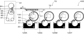
- the image forming apparatus of the present invention includes at least a colorant flying device, and further includes other means as necessary.
- the colorant flying device is the light absorbing material flying device in which the light absorbing material is the colorant and is caused to fly by the colorant flying means.
- the image forming method of the present invention includes at least the colorant flying step, and further includes other steps as necessary.
- the colorant flying step is the light absorbing material flying step in which the light absorbing material is the colorant.
- the colorant flying step is the light absorbing material flying step in which the light absorbing material is the colorant.
- the image forming method can be preferably performed by the image forming apparatus, the colorant flying step can be preferably performed by the colorant flying means, and the other steps can be performed by the other means. be able to.
- the colorant flying means is the same as the light absorbing material flying means described above except that the light absorbing material is the colorant and the adherend is the recording medium, and the description thereof is omitted.
- the colorant flying step is the same as the light absorbing material flying method described above except that the light absorbing material is the colorant and the adherend is the recording medium. .
- Examples of the other means include a colorant supply unit, a beam scanning unit, a recording medium transport unit, a fixing unit, and a control unit.
- the colorant flying means, the colorant supply means, and the beam scanning means may be handled as a colorant flying unit.
- four colorant flying units may be provided in the image forming apparatus, and the colorants yellow, magenta, cyan, and black that are process colors may be caused to fly.
- a white hiding layer is provided by arranging the colorant flying unit having the white colorant on the upstream side of the colorant flying unit having the colorant of the process color in the conveyance direction of the recording medium. Therefore, an image having excellent color reproducibility can be formed on the transparent recording medium.
- the laser light source is, for example, a blue laser beam or an ultraviolet laser beam so that the transmittance of light having the wavelength of the optical vortex laser beam is 70% or less. It may be necessary to change to the laser light source that generates the above.
- the powder or the highly viscous colorant can be used, even if the colorant of different colors is sequentially stacked on the recording medium, the colorant is not formed. Since bleeding that exudes and intermingles can be suppressed, a high-quality color image can be obtained.
- only one colorant flying unit is provided, and the colorant itself supplied to the supply roller and the colorant carrier is switched to form a multi-color image. It may be.
- the other processes include a colorant supply process, a beam scanning process, a recording medium conveyance process, a fixing process, and a control process.
- Colorant supply means and colorant supply process >> In the colorant supplying means and the colorant supplying step, the light absorbing material supplying means and the light absorbing material described above except that the light absorbing material is the colorant and the adherend is the recording medium. Since it is the same as the supply process, the description thereof is omitted.
- Beam scanning means and beam scanning process are the same as the beam scanning unit and the beam scanning step described above except that the light absorbing material is the colorant and the adherend is the recording medium. Therefore, the description is omitted.
- Recording medium conveying means and recording medium conveying process >> In the recording medium conveying means and the recording medium conveying step, the adherend conveying means and the adherend described above are used except that the light absorbing material is the colorant and the adherend is the recording medium. Since it is the same as the kimono transport process, its description is omitted.
- the fixing unit and the fixing step in the image forming apparatus include the fixing unit and the fixing unit in the light absorbing material flying device, except that the light absorbing material is the colorant and the adherend is the recording medium. Since this is the same as the fixing step, description thereof is omitted.
- Control means and control process Since the control means and the control process in the image forming apparatus are the same as the control means and the control process in the light absorbing material flying apparatus, description thereof is omitted.
- the colorant is not particularly limited with respect to its shape, material, etc., as with the light absorbing material, and can be appropriately selected according to the purpose. Hereinafter, differences when the light absorbing material is used as the colorant will be described.
- the colorant of the powder is not particularly limited and may be appropriately selected depending on the intended purpose. However, like a toner used in an electrophotographic system, a powder containing a binder resin is preferable.
- the binder resin is not particularly limited and may be appropriately selected depending on the intended purpose.
- the binder resin used in the electrophotographic toner has a function of fixing the recording medium to the recording medium. It is preferable at the point which provides the function for forming a layer uniformly on the surface.
- the binder resin used for the electrophotographic toner is not particularly limited and may be appropriately selected depending on the intended purpose.
- Examples thereof include general-purpose resins such as polyesters and styrene copolymers.
- the polyester is preferable in that it has a high affinity with paper, which is a typical recording medium, and has good fixability.
- the said polyester has a molecular structure similar to the aliphatic ester compound used as a softening agent, it is preferable also at a point with high compatibility.
- Examples of the monomer constituting the polyester include a divalent alcohol component, a trihydric or higher polyhydric alcohol component, an acid component that forms a polyester polymer, and a trivalent or higher polyvalent carboxylic acid component.
- Examples of the divalent alcohol component include ethylene glycol, propylene glycol, 1,3-butanediol, 1,4-butanediol, 2,3-butanediol, diethylene glycol, triethylene glycol, and 1,5-pentanediol.
- 1,6-hexanediol 1,6-hexanediol, neopentyl glycol, 2-ethyl-1,3-hexanediol, hydrogenated bisphenol A, or a diol obtained by polymerizing bisphenol A with a cyclic ether such as ethylene oxide or propylene oxide Is mentioned.
- a cyclic ether such as ethylene oxide or propylene oxide Is mentioned.
- examples of the trihydric or higher polyhydric alcohol component include sorbitol, 1,2,3,6-hexanetetrol, 1,4-sorbitan, pentaerythritol, dipentaerythritol, tripentaerythritol, 1,2,4.
- Examples of the acid component that forms the polyester polymer include benzene dicarboxylic acids or anhydrides thereof, alkyldicarboxylic acids or anhydrides thereof, unsaturated dibasic acids, unsaturated dibasic acid anhydrides, and the like.
- Examples of the benzene dicarboxylic acids include phthalic acid, isophthalic acid, terephthalic acid, and the like.
- alkyldicarboxylic acids examples include succinic acid, adipic acid, sebacic acid, azelaic acid, and the like.
- unsaturated dibasic acid examples include maleic acid, citraconic acid, itaconic acid, alkenyl succinic acid, fumaric acid, and mesaconic acid.
- unsaturated dibasic acid anhydride examples include maleic acid anhydride, citraconic acid anhydride, itaconic acid anhydride, alkenyl succinic acid anhydride, and the like.
- trivalent or higher polyvalent carboxylic acid component examples include, for example, trimet acid, pyromet acid, 1,2,4-benzenetricarboxylic acid, 1,2,5-benzenetricarboxylic acid, 2,5,7-naphthalenetricarboxylic acid.
- 1,2,4-naphthalenetricarboxylic acid 1,2,4-butanetricarboxylic acid, 1,2,5-hexanetricarboxylic acid, 1,3-dicarboxy-2-methyl-2-methylenecarboxypropane, tetra ( Methylenecarboxy) methane, 1,2,7,8-octanetetracarboxylic acid, empole trimer acid, or anhydrides thereof, partial lower alkyl esters, and the like.
- styrene copolymer examples include a styrene-p-chlorostyrene copolymer, a styrene-propylene copolymer, a styrene-vinyltoluene copolymer, a styrene-vinylnaphthalene copolymer, and a styrene-methyl acrylate copolymer.
- polymer Polymer, styrene-ethyl acrylate copolymer, styrene-butyl acrylate copolymer, styrene-octyl acrylate copolymer, styrene-methyl methacrylate copolymer, styrene-ethyl methacrylate copolymer, styrene- Butyl methacrylate copolymer, styrene- ⁇ -chloromethyl methacrylate copolymer, styrene-acrylonitrile copolymer, styrene-vinyl methyl ketone copolymer, styrene-butadiene copolymer, styrene-isoprene copolymer, styrene -Acrylonitrile-indene copolymer, Styrene - maleic acid copolymer, styrene -
- a glass transition point of the said binder resin there is no restriction
- the glass transition point is within a preferred range, the heat-resistant storage stability of the binder resin can be maintained, and a layer can be easily formed on the surface of the colorant-carrying member, and the recording can be performed with heat, pressure, or the like. This is advantageous in that the energy for fixing the colorant to the medium can be reduced.
- the liquid colorant is not particularly limited and may be appropriately selected depending on the intended purpose.
- a water-based ink in which a dye, a pigment, colored particles, colored oil droplets, and the like are dispersed in water as a solvent.
- a solvent such as a hydrocarbon organic solvent or various alcohols
- the water-based ink is preferable from the viewpoints of safety of volatile components and risk of explosion.
- the image forming apparatus can form an image using process ink for offset printing using a plate, ink corresponding to JAPAN COLOR, special color ink, etc., a digital image corresponding to the color used for offset printing can be easily obtained without a plate. Can be reproduced. Further, since image formation is possible with UV curable ink, blocking by overlapping the recording medium can be prevented and the drying process can be simplified by curing by irradiating with ultraviolet rays in the fixing process.
- Examples of the material of the colorant include organic pigments, inorganic pigments, and dyes. These may be used individually by 1 type and may use 2 or more types together.
- organic pigment examples include dioxazine violet, quinacridone violet, copper phthalocyanine blue, phthalocyanine green, sap green, monoazo yellow, disazo yellow, polyazo yellow, benzimidazolone yellow, isoindolinone yellow, first yellow, chromophthale Yellow, nickel azo yellow, azomethine yellow, benzimidazolone orange, alizarin red, quinacridone red, naphthol red, monoazo red, polyazo red, perylene red, anthraquinonyl red, diketopyrrolopyrrole red, diketopyrrolopyrrole orange, benzimidazolo Ron Brown, Sepia, Aniline Black, etc., and among the organic pigments, as a metal lake pigment, In example, rhodamine lake, quinoline yellow lake, such as the brilliant blue lake, and the like.
- the inorganic pigment examples include cobalt blue, cerulean blue, cobalt violet, cobalt green, zinc white, titanium white, titanium yellow, chrome titanium yellow, light red, chrome oxide green, mars black, viridan, yellow ocher, Alumina white, cadmium yellow, cadmium red, vermilion, lithopone, ultramarine, talc, white carbon, clay, mineral violet, rose cobalt violet, silver white, calcium carbonate, magnesium carbonate, zinc oxide, zinc sulfide, strontium sulfide, aluminum Strontium acid, brass, gold powder, bronze powder, aluminum powder, brass pigment, ivory black, peach black, lamp black Carbon Black, Prussian Blue, Aureolin, Mica Titanium, Yellow Ocher, Tail Belt, Roshenna, Low Umber, Cassel Earth, Chalk, Plaster, Burnt Senna, Burnt Amber, Lapis Lazuli, Azurite, Malachite, Oupiment, Chin Sand, Powder, Pepper , Bengala, ultra
- black pigment carbon black is preferable from the viewpoint of hue and image storage stability.
- cyan pigment C.I. which is copper phthalocyanine blue from the viewpoint of hue and image storage stability.
- I. Pigment Blue 15: 3 is preferable.
- quinacridone red C.I. I. Pigment Red 122 a naphthol red C.I. I. Pigment Red 269, and C.I. I. Pigment Red 81: 4 is preferable, and these may be used alone or in combination of two or more.
- C.I. I. Pigment red 122 and C.I. I. More preferred is a mixture of CI Pigment Red 269, C.I. I. Pigment red 122 (PR 122) and C.I. I.
- a mixture in which 269 is 5:95 or more and 80:20 or less is particularly preferable.
- C.I. I. Pigment Yellow 74 C.I. I. Pigment Yellow 155, benzimidazolone yellow C.I. I. Pigment Yellow 180, an isoindoline yellow C.I. I. Pigment Yellow 185 is preferable.
- C.I. I. Pigment Yellow 185 is more preferable. These may be used individually by 1 type and may use 2 or more types together.
- the light absorbing material When used as a process color toner as the colorant, it is preferably used in the four-color toner set.
- the inorganic pigment is often composed of particles having a volume average particle diameter exceeding 10 ⁇ m.
- the colorant is preferably a liquid. If the colorant is a liquid, it is advantageous in that the colorant can be maintained in a stable state without using a force other than non-electrostatic adhesion such as electrostatic force.
- the image forming method of the present invention is very effective as compared with the ink jet recording method in which nozzle clogging or ink sedimentation is likely to be noticeable and a stable continuous printing process is difficult to expect.
- the image forming method of the present invention is very effective even when compared with an electrophotographic method in which a sufficient charge amount cannot be obtained when the surface area of the particles of the colorant is reduced and a stable continuous printing process is not realized. is there.
- the dye examples include a monoazo dye, polyazo dye, metal complex azo dye, pyrazolone azo dye, stilbene azo dye, thiazole azo dye, anthraquinone derivative, anthrone derivative, indigo derivative, thioindigo derivative, phthalocyanine dye, diphenylmethane dye, triphenyl
- examples include methane dye, xanthene dye, acridine dye, azine dye, oxazine dye, thiazine dye, polymethine dye, azomethine dye, quinoline dye, nitro dye, nitroso dye, benzoquinone dye, naphthoquinone dye, naphthalimide dye, and perinone dye.
- Viscosity of Colorant There is no restriction
- the colorant adhering to the recording medium may cause feathering or bleeding, but can be handled by the image forming apparatus of the present invention.
- the colorant has a high viscosity, it dries faster than the permeation rate into the recording medium, so it can improve color development and sharpen edges by reducing bleeding. can do.
- gradation expression is performed by overprinting in which the colorant is deposited and adhered, bleeding due to an increase in the amount of the colorant can be reduced.
- this image forming method is a method in which the liquid colorant is ejected and adhered, for example, compared with a so-called thermal transfer method in which the colorant is melt-transferred by heat from the film-like colorant carrier. Even if minute irregularities exist in the recording medium, recording can be performed satisfactorily.
- Average thickness of colorant There is no restriction
- the preferred range of the average thickness varies depending on the recording medium, purpose, and the like.
- the thickness is preferably 0.5 ⁇ m or more and 5 ⁇ m or less.
- the average thickness is within a preferable range, a color difference due to a minute difference in the average thickness of the recording medium is difficult to discriminate even by human eyes, so that the coated paper is likely to have a highly saturated image, and a halftone dot. This is advantageous in that the dot gain is not remarkable and a sharp image can be easily expressed.
- the recording medium having a surface roughness larger than that of coated paper or film, such as high-quality paper used in offices it is preferably 3 ⁇ m to 10 ⁇ m.
- the average thickness is within a preferable range, it is easy to obtain a good image quality that is not easily affected by the surface roughness of the recording medium, and in particular, when expressing a full color image with the colorant of the process color, Even when the colorant layers are overlapped, the difference in level is hardly noticeable.
- the average thickness of 5 ⁇ m or more may be required to attach the colorant to cotton, silk, chemical fibers, etc., which will be the recording medium. Many. This is because the thickness of the fiber is larger than that of paper, so that a large amount of the colorant is often required.
- the colorant carrier is the same as the light absorber carrier in the light absorber flying device except that the light absorber is the colorant, and the description thereof is omitted.
- ⁇ Recording medium> There is no restriction
- the light absorbing material in the light absorbing material flying device except that the light absorbing material is the colorant and the adherend is the recording medium. And the description of the gap between the light absorbing material carrier and the description thereof is omitted.
- the manufacturing apparatus of the three-dimensional molded item of this invention has at least a three-dimensional modeling agent flight apparatus, and also has another means as needed.
- the three-dimensional modeling agent flying device is the light absorbing material flying device in which the light absorbing material is the three-dimensional modeling agent and is caused to fly by the three-dimensional modeling agent flying means.
- the manufacturing method of the three-dimensional molded item of this invention contains the said three-dimensional modeling agent flight process at least, and also includes another process as needed.
- the three-dimensional modeling agent flying step is the light absorbing material flying step in which the light absorbing material is the three-dimensional modeling agent.
- the manufacturing method of the three-dimensional modeled object can be preferably performed by the manufacturing apparatus of the three-dimensional modeled object, the three-dimensional model agent flying step can be preferably performed by the three-dimensional modeled agent flying means, and the other processes. Can be performed by the other means.
- the light absorbing material flying means is the same as the light absorbing material flying means described above except that the light absorbing material is the three-dimensional modeling agent and the adherend is the modeled object supporting substrate. Description is omitted.
- the light absorbing material flying means stacks the three-dimensional modeling agent as a layer on the three-dimensional object support substrate, and three-dimensionally attaches the three-dimensional modeling agent.
- the three-dimensional modeling agent flying step is the same as the above-described light absorbing material flying step except that the light absorbing material is the three-dimensional modeling agent and the adherend is the modeled object supporting substrate. Description is omitted.
- the three-dimensional modeling agent flying step includes a step in which the light absorbing material flying means three-dimensionally attaches the three-dimensional modeling agent to the three-dimensional object support substrate.
- ⁇ 3D modeling agent curing means and 3D modeling agent curing step> There is no restriction
- Examples of the other means include a three-dimensional modeling agent supply unit, a three-dimensional modeling head unit scanning unit, a substrate position adjusting unit, and a control unit.
- substrate position adjustment process, a control process, etc. are mentioned, for example.
- the three-dimensional modeling head unit scanning unit is not particularly limited and may be appropriately selected depending on the purpose.
- the three-dimensional modeling head unit in which the light absorber flying unit and the ultraviolet irradiation unit are integrated is formed as the modeling unit. You may make it scan on the width direction (X-axis) of an apparatus on an object support substrate.
- the three-dimensional modeling head unit cures the ultraviolet curable three-dimensional modeling agent attached to the light absorber flying unit by the ultraviolet irradiation means.
- a plurality of the three-dimensional modeling head units may be provided.
- the three-dimensional modeling head unit scanning step is not particularly limited as long as it is a step of scanning the three-dimensional modeling head unit, and can be appropriately selected according to the purpose. For example, the three-dimensional modeling head unit scanning unit is preferable. Can be done.
- Substrate Position Adjustment Unit and Substrate Position Adjustment Step There is no restriction
- the substrate position adjusting step is not particularly limited as long as it is a step of adjusting the position of the model support substrate, and can be appropriately selected according to the purpose.
- the substrate position adjusting unit is preferably used. It can be carried out.
- Control means and control process Since the control means and the control process are the same as the control means and the control process of the light absorbing material flying device described above, description thereof will be omitted.
- the average thickness of the three-dimensional modeling agent is not particularly limited and may be appropriately selected depending on the intended purpose.
- the thickness varies depending on the required precision, but is preferably 5 ⁇ m or more and 500 ⁇ m or less.
- the average thickness is within a preferable range, it is advantageous in terms of accuracy, texture, smoothness, manufacturing time, and the like of the three-dimensional structure.
- an average thickness of the said three-dimensional modeling agent 5 micrometers or more and 100 micrometers or less are more preferable.
- the average thickness is within a more preferable range, it is advantageous in that the energy of the optical vortex laser beam can be suppressed low and deterioration of the three-dimensional modeling agent can be suppressed.
- the solid modeling agent contains a curable material, and further contains other components as necessary.
- the curable material is not particularly limited as long as it is a compound that causes a polymerization reaction by irradiation with active energy rays (ultraviolet rays, electron beams, etc.), heating, and the like, and can be appropriately selected according to the purpose.
- Active energy ray-curable compounds include thermosetting compounds, and the like.
- materials that are liquid at room temperature are preferable.
- the active energy ray-curable compound is a relatively low viscosity monomer having an unsaturated double bond capable of radical polymerization in the molecular structure, and examples thereof include a monofunctional monomer and a polyfunctional monomer.
- the other components are not particularly limited and may be appropriately selected depending on the purpose.
- water, organic solvents, photopolymerization initiators, surfactants, colorants, stabilizers, water-soluble resins examples include low-boiling alcohols, surface treatment agents, viscosity modifiers, adhesion-imparting agents, antioxidants, anti-aging agents, crosslinking accelerators, ultraviolet absorbers, plasticizers, preservatives, and dispersants.
- Modeling object support substrate> There is no restriction
- the gap between the modeling object support substrate and the three-dimensional modeling agent carrier is the same as the gap between the adherend and the three-dimensional modeling agent carrier, description thereof is omitted.
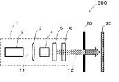
- FIG. 4A is an explanatory view showing an example of the light absorbing material flying device of the present invention.
- the light absorbing material flying device 300 includes a light absorbing material flying means 1, a light absorbing material 20, and an adherend 30, and the light absorbing material 20 that absorbs light has a light absorbing material.
- the flying means 1 irradiates the optical vortex laser beam 12 corresponding to the light absorption wavelength of the light absorbing material, and the energy of the optical vortex laser beam 12 causes the light absorbing material 20 to fly in the irradiation direction and adhere to the adherend 30.
- Device irradiates the optical vortex laser beam 12 corresponding to the light absorption wavelength of the light absorbing material, and the energy of the optical vortex laser beam 12 causes the light absorbing material 20 to fly in the irradiation direction and adhere to the adherend 30.
- the light absorbing material flying means 1 includes a laser light source 2, a beam diameter changing means 3, a beam wavelength changing means 4, an optical vortex converter 5, and an energy adjustment filter 6.
- the laser light source 2 is, for example, a titanium sapphire laser, generates a pulsed laser beam 11 and irradiates the beam diameter changing means 3.
- the beam diameter changing means 3 is, for example, a condensing lens, and is arranged downstream of the laser light source 2 in the optical path of the laser beam 11 generated by the laser light source 2 and changes the diameter of the laser beam 11.
- the beam wavelength changing means 4 is, for example, a KTP crystal and is arranged downstream of the beam diameter changing means 3 in the optical path of the laser beam 11 and changes the wavelength of the laser beam 11 to a wavelength that can be absorbed by the light absorbing material 20.
- the optical vortex conversion unit 5 is, for example, a spiral phase plate and is arranged downstream of the beam wavelength changing means 4 in the optical path of the laser beam 11 and converts the laser beam 11 into an optical vortex laser beam 12.
- the energy adjustment filter 6 is made of, for example, glass having a low transmittance of the optical vortex laser beam 12 and is disposed downstream of the optical vortex conversion unit 5 in the optical path of the optical vortex laser beam 12. In order to fly the light absorption material 20, it changes into an appropriate energy.
- the light absorbing material 20 is irradiated with the optical vortex laser beam 12 that has passed through the energy adjustment filter 6, receives the energy in the range of the diameter of the optical vortex laser beam 12, flies, and adheres to the adherend 30.
- the flying light absorbing material 20 adheres to the adherend 30 while its scattering to the periphery is suppressed by the gyro effect imparted by the optical vortex laser beam 12.
- the flying amount of the flying light absorbing material 20 is part or all of the area of the light absorbing material 20 irradiated with the optical vortex laser beam 12, and can be adjusted by the energy adjustment filter 6 or the like.
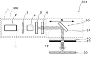
- FIG. 4B is an explanatory view showing another example of the light absorbing material flying device of the present invention.
- the light absorbing material flying device 301 includes a light absorbing material carrier 40 and a beam scanning means 60 in addition to each unit of the light absorbing material flying device 300 shown in FIG. 4A.
- the light absorbing material flying device 301 scans the optical vortex laser beam 12 generated by the light absorbing material flying means 1 in a direction perpendicular to the irradiation direction of the optical vortex laser beam 12 by the beam scanning means 60, and has a flat plate shape. It is possible to attach the light absorbing material 20 which has been irradiated and irradiated to an arbitrary position of the light absorbing material 20 carried by the light absorbing material carrying body 40 to the adherend 30.
- the beam scanning means 60 is disposed downstream of the light absorbing material flying means 1 in the optical path of the optical vortex laser beam 12 and has a reflecting mirror 61.
- the reflecting mirror 61 is moved in a scanning direction indicated by an arrow S in FIG. 4B by reflecting mirror driving means (not shown), and reflects the optical vortex laser beam 12 to an arbitrary position of the light absorbing material 20.
- the beam scanning unit 60 moves, for example, the light absorbing material flying unit 1 itself, rotates the light absorbing material flying unit 1 to change the irradiation direction of the optical vortex laser beam 12, or polygons as the reflecting mirror 61.
- the optical vortex laser beam 12 may be scanned at an arbitrary position by using a mirror.
- the light absorbing material carrier 40 is disposed downstream of the beam scanning means 60 in the optical path of the optical vortex laser beam 12.
- the light absorbing material 20 is a highly viscous liquid
- the light absorbing material carrier 40 is capable of transmitting light, supports the light absorbing material 20 on the surface, and is irradiated with the optical vortex laser beam 12 from the back surface.
- the flying amount of the light absorbing material 20 is controlled. It can be stabilized.
- a combination of the light absorbing material flying means 1 and the beam scanning means 60 is referred to as an optical vortex laser beam irradiation unit 100.
- FIG. 5A is an explanatory diagram illustrating an example of the light absorbing material flying device illustrated in FIG. 4B to which a light absorbing material supply unit and an adherend conveying unit are added.
- the light absorbing material flying device 302 has a light absorbing material supply means 50 and an adherend transport means 70 in addition to each means of the light absorbing material flying device 301 shown in FIG. 4B.
- the flat light absorbing material carrier 40 is changed to a cylindrical light absorbing material carrying roller 41.
- an optical vortex laser beam irradiation unit 100 is disposed inside the light absorbing material carrying roller 41, and irradiates the adherend 30 carried on the outer periphery by the light absorbing material carrying roller 41 with the optical vortex laser beam 12. .
- the light absorbing material supply unit 50 includes a storage tank 51, a supply roller 52, and a regulation blade 53.
- the storage tank 51 is disposed near the lower portion of the supply roller 52 and stores the light absorbing material 10.
- the supply roller 52 is disposed so as to be in contact with the light absorbing material carrying roller 41, and a part thereof is immersed in the light absorbing material 10 of the storage tank 51, and is provided by a rotational driving means (not shown) or by the light absorbing material carrying roller 41.
- the light absorbing material 10 is attached to the surface while rotating in the rotation direction indicated by the arrow R2 in FIG.
- the adhering light absorbing material 10 is supplied as a layer by making the average thickness uniform by the regulating blade 53 and transferring to the light absorbing material carrying roller 41.
- the light absorbing material 10 supplied to the surface of the light absorbing material carrying roller 41 is continuously supplied to the position where the optical vortex laser beam 12 is irradiated as the light absorbing material carrying roller 41 rotates.
- the regulating blade 53 is arranged on the upstream side of the light absorbing material carrying roller 41 in the rotation direction indicated by the arrow R2 in the figure, regulates the light absorbing material 10 attached to the surface by the supply roller 52, and the light absorbing material carrying roller 41.
- the average thickness of the light absorbing material 10 supplied to is made uniform.
- the adherend transporting means 70 is disposed in the vicinity of the light absorbing material carrying roller 41 so that the light absorbing material carrying roller 41 and the transported material 30 to be transported do not come into contact with each other. And an adherend transport belt 72 stretched around a roller 71.
- the adherend transport means 70 rotates the adherend transport roller 71 by a rotation driving means (not shown), and transports the adherend 30 in the transport direction indicated by an arrow C in FIG. 5A by the adherend transport belt 72.
- the optical vortex laser beam irradiation unit 100 irradiates the optical vortex laser beam 12 from the inside of the light absorbing material carrying roller 41 according to the image information, and attaches the light absorbing material 20 to the adherend 30.
- a two-dimensional image is formed on the adherend 30 by performing an attaching operation for attaching the light absorbing material 20 to the adherend 30 while moving the adherend 30 by the adherend transport belt 72. be able to.
- the light absorbing material 20 carried on the surface of the light absorbing material carrying roller 41 but not flying is accumulated by the contact of the light absorbing material carrying roller 41 with the supply roller 52, and eventually the storage tank. It falls to 51 and is collected.
- the method for collecting the light absorbing material 20 is not limited thereto, and a scraper for scraping the light absorbing material 20 on the surface of the light absorbing material carrying roller 41 may be provided.
- FIG. 5B is an explanatory view showing another example of the light absorbing material flying device shown in FIG. 4B to which the light absorbing material supply means and the adherend transport means are added.
- the light absorbing material flying device 303 is a light absorbing material carrying portion 42 obtained by dividing the cylindrical light absorbing material carrying roller 41 in the light absorbing material flying device 302 shown in FIG. 5A into two along the axial direction. The arrangement of the light absorbing material flying device 302 is changed.
- the light-absorbing material-carrying portion 42 is a part of a cylindrical surface, and has a shape with no surface on the opposite side of the cylindrical center line.
- FIG. 5C is an explanatory view showing another example of the light absorbing material flying device shown in FIG. 4B to which the light absorbing material supply means and the adherend conveying means are added.
- the light absorbing material flying device 304 is obtained by changing the position of the regulating blade 53 in the light absorbing material flying device 302 shown in FIG. 5A.
- the light absorbing material flying device 304 is preferably used particularly when the light absorbing material 20 is powder.
- the regulating blade 53 regulates the carrying amount of the light absorbing material 20 supplied from the light absorbing material supply means 50 to the light absorbing material carrying roller 41 with the regulating blade 53 disposed in the vicinity of the light absorbing material carrying roller 41.
- the arrangement of the regulating blade 53 is the same as the arrangement of the regulating blade in a means for supplying toner to a developing roller of a general electrophotographic one-component developing machine, for example.
- FIG. 6A is an explanatory diagram illustrating an example of the light absorbing material flying device illustrated in FIG. 5A to which a fixing unit is added.
- a light absorbing material flying device 305 has a fixing means 80 in addition to each means of the light absorbing material flying device 302 shown in FIG. 5A, and the light absorbing material attached to the adherend 30. 20 is fixed and smoothed.
- the position of the adherend conveying means 70 is on the side surface of the light absorbing material carrying roller 41 in FIG. 5A, it is above the light absorbing material carrying roller 41 in FIG. 6A for convenience of explanation.
- the fixing unit 80 is a pressure type fixing unit, and is disposed on the downstream side of the light absorbing material carrying roller 41 in the conveyance direction indicated by an arrow C in FIG. And a roller 84.
- the fixing unit 80 pressurizes and fixes the adherend 30 to which the light absorbing material 20 is adhered by conveying the object 30 while sandwiching it.
- the pressure roller 83 is urged toward the counter roller 84, the surface is in contact with the adherend 30, and pressurizes while the adherend 30 is sandwiched by the counter roller 84.
- the opposing roller 84 is disposed at a position where it comes into contact with the pressure roller 83 and sandwiches the adherend 30 with the pressure roller 83 via the adherend transport belt 72.
- the light absorbing material flying device 305 when the light absorbing material 20 having a very high viscosity of 1,000 mPa ⁇ s or more is used, the light absorbing material 20 is attached to the adherend 30. If the penetration or wetting is delayed and drying is performed as it is, the surface roughness of the image becomes rough and the gloss of the image may be lowered. In such a case, by having the fixing means 80, the adherend 30 to which the light absorbing material 20 is attached is pressed by the pressure roller 83, and the light absorbing material 20 is pushed into the adherend 30 or the light absorbing material 20 is applied. Therefore, it is possible to reduce the surface roughness of the adherend 30 to which the light absorbing material 20 is attached.
- FIG. 6B is an explanatory diagram showing another example of the light absorber flying device shown in FIG. 5A to which a fixing unit is added.
- a light absorbing material flying device 306 is obtained by changing the pressure-type fixing unit 80 in the light absorbing material flying device 305 shown in FIG.
- the fixing unit 81 is disposed on the downstream side of the light absorbing material carrying roller 41 in the conveyance direction indicated by an arrow C in FIG. 6B of the adherend 30, and includes a heating and pressing roller 85, a fixing belt 86, a driven roller 87, A halogen lamp 88 and a counter roller 84 are provided.
- the fixing means 81 heats and presses and fixes the adherend 30 to which the light absorbing material 20 is adhered, for example, so that, for example, powder light absorbing material such as toner for electrophotography and powder coating material is used. This is used when it is used as 20 or when it is used as a light absorbing material 20 of a dispersion in which a material that needs to be melted is dispersed, and a target image cannot be obtained only by pressurization.
- the heating and pressing roller 85 is biased toward the opposing roller 84, and heats and presses the adherend 30 with the opposing roller 84 via the fixing belt 86.
- the fixing belt 86 has an endless belt shape, is stretched around the heat and pressure roller 85 and the driven roller 87, and the surface contacts the adherend 30.
- the driven roller 87 is disposed below the heating and pressing roller 85 and is driven according to the rotation of the heating and pressing roller 85.
- the halogen lamp 88 is disposed inside the heat and pressure roller 85 and generates heat for fixing the light absorbing material 20 to the adherend 30.
- the facing roller 84 is disposed at a position where it comes into contact with the fixing belt 86, and the object 30 is clamped by the pressure roller 83 via the object conveying belt 72.
- FIG. 6C is an explanatory diagram showing another example of the light absorbing material flying device shown in FIG. 5A to which a fixing unit is added.
- a light absorbing material flying device 307 is obtained by changing the pressure-type fixing unit 80 in the light absorbing material flying device 305 shown in FIG. 6A to a UV irradiation type fixing unit 82.
- the fixing unit 82 is disposed on the downstream side of the light absorbing material carrying roller 41 in the conveyance direction indicated by an arrow C in FIG. 6C of the adherend 30 and has a UV lamp 89.
- the fixing unit 81 is used when an ultraviolet curable material is used as the light absorbing material 20, and is fixed to the adherend 30 by irradiating UV with a UV lamp 89.
- FIG. 7A is an explanatory diagram showing an example of the image forming apparatus of the present invention.
- an image forming apparatus 200 includes a light absorbing material supply unit 50, a light absorbing material flying unit 1, a beam scanning unit 60, in addition to each unit of the light absorbing material flying device 306 shown in FIG. 6B.
- Three light absorber flying units 120 constituted by the light absorber carrying roller 41 and the light absorber 20 are further provided, and the light absorber 20 is changed to the colorant 21.
- the light absorber flying units 120Y, 120M, 120C, and 120K store toners of four colors, yellow (Y), magenta (M), cyan (C), and black (K), which are process colors, as the colorant 21, respectively. ing. Thereby, it is possible to apply to a color process in which an image of each color is sequentially formed on the recording medium 31 and a color image is obtained.
- FIG. 7B is an explanatory diagram showing another example of the image forming apparatus of the present invention.
- the image forming apparatus 201 includes an intermediate transfer unit 90 in addition to the units of the image forming apparatus 200 illustrated in FIG. 7A.
- the intermediate transfer unit 90 includes an intermediate transfer member 91, an intermediate transfer member driving roller 92, and an intermediate transfer member driven roller 93.
- the intermediate transfer member 91 is, for example, an endless belt, is disposed above the four light absorber flying units 120, and is stretched by an intermediate transfer member driving roller 92 and an intermediate transfer member driven roller 93. .
- the intermediate transfer member driving roller 92 is rotated in a rotation direction indicated by an arrow R2 in FIG. 7B by a rotation driving unit (not shown) to rotate the intermediate transfer member 91.
- the intermediate transfer member driven roller 93 is driven according to the rotation of the intermediate transfer member driving roller 92.
- an image may be formed on the intermediate transfer member 91 and transferred to a desired recording medium 31.
- a high-quality color image can be obtained in the same manner as the image forming apparatus 200.
- the image formed on the intermediate transfer member 91 is pressed by the intermediate transfer member driving roller 92 when the image is transferred to the recording medium 31, the surface of the recording medium 31 to which the colorant 21 is adhered is the same as in the image forming apparatus 200. Roughness can be reduced.
- FIG. 8 is an explanatory diagram illustrating an example of a manufacturing apparatus for a three-dimensional structure according to the present invention.
- the three-dimensional object manufacturing apparatus 500 includes a three-dimensional object support substrate 122, a stage 123, and a three-dimensional object head unit 130.
- the three-dimensional object manufacturing apparatus 500 manufactures a three-dimensional object 124 by laminating the attached three-dimensional object 22 while curing.
- the three-dimensional modeling head unit 130 is disposed on the upper part of the three-dimensional model manufacturing apparatus 500, and can be scanned in a direction indicated by an arrow L in the drawing by a driving unit (not shown).
- the three-dimensional modeling head unit 130 includes a light absorber flying unit 120 and an ultraviolet irradiator 121.
- the light absorber flying unit 120 is disposed at the center of the three-dimensional modeling head unit 130, and causes the light absorber 20 to fly downward and adhere to the model support substrate 122 or the already cured light absorber 20.
- the ultraviolet irradiator 121 is disposed on both side surfaces of the light absorber flying unit 120, and irradiates and cures the light absorber 20 which has been caused to fly by the light absorber flying unit 120.
- the three-dimensional object support substrate 122 is disposed below the three-dimensional object manufacturing apparatus 500 and serves as a substrate when the three-dimensional object head unit 130 forms the layer of the three-dimensional object 22.
- the stage 123 is disposed below the model support substrate 122, and the model support substrate 122 can be moved in the vertical direction in the drawing by a driving unit (not shown). Further, the stage 123 can be moved in the direction indicated by the arrow H in the drawing, and the gap between the three-dimensional model head unit 130 and the three-dimensional model 124 can be adjusted.
- the adherend, the recording medium, and the modeled object supporting substrate are transported or moved.
- the light-absorbing material flying unit or the like may be moved while the adherend is stationary, or both may be moved. In the case where images on the entire surface of the recording medium are formed simultaneously, at least at the time of recording, both may be stationary and only the laser may be operated.
- the present invention is not limited to these examples. Similar to the light absorbing material flying means shown in FIG. 4A, the light absorbing material flying means is configured to irradiate the light absorbing material with one pulse of the optical vortex laser beam that is pulse-oscillated, and A specific example in which one dot is attached to the adherend will be described.
- Example 1 ⁇ Light absorber support, light absorber and adherend>
- slide glass manufactured by Matsunami Glass Industrial Co., Ltd., micro slide glass S7213, transmittance of light of 532 nm wavelength is 99%
- offset UV ink manufactured by T & Ktoka, UV -TML2 red, viscosity 100 Pa ⁇ s
- the transmittance of light having a wavelength of 532 nm in the layered light absorbing material was 1%.
- the viscosity was measured in a 25 ° C.
- the light absorbing material carrier was installed so that the surface to which the light absorbing material was applied was opposed to the adherend, and the optical vortex laser beam could be irradiated vertically from the back surface of the light absorbing material.
- POD gloss coated paper manufactured by Mitsubishi Paper Industries
- the gap between the adherend and the light absorbing material was 1.5 mm.
- the light absorbing material flying means is similar to the light absorbing material flying means shown in FIG. 4A.
- the laser light source a laser light source made in the Omatsu Laboratory, graduate School of Interdisciplinary Sciences, Chiba University was used.
- the wavelength was 1,064 nm
- the beam diameter was 1.25 mm ⁇ 1.23 mm
- the pulse width was 2 nanoseconds
- the pulse frequency was 20 Hz. 1 pulse laser beam was generated.
- the diameter was 400 ⁇ m ⁇ 400 ⁇ m.
- the laser beam passed through the beam diameter changing member was irradiated to a KTP crystal (manufactured by CESTTECH) used as the beam wavelength changing element, and the wavelength was changed from 1,064 nm to 532 nm.
- a KTP crystal manufactured by CESTTECH
- the wavelength was changed from 1,064 nm to 532 nm.
- it was converted into the optical vortex laser beam by passing through a spiral phase plate (Voltex phase plate, manufactured by Luminex) as the optical vortex converter.
- the energy adjustment filter manufactured by Sigma Kogyo Co., Ltd., ND filter
- FIG. 9A shows the attachment state of the adherend to which the light absorbing material that has been made to fly adheres.
- the adhesion state was evaluated according to the following criteria, and the results are shown in Table 1. In addition, if this evaluation is (circle) or (triangle
- Example 2 In Example 1, the adhesion state was evaluated in the same manner as in Example 1 except that the laser output when the light absorbing material was irradiated was 0.35 mJ / dot. The adhesion state is shown in FIG. 9B and the results are shown in Table 1.
- Example 3 In Example 1, the adhesion state was evaluated in the same manner as in Example 1 except that the laser output when irradiating the light absorbing material was 0.25 mJ / dot. The adhesion state is shown in FIG. 9C and the results are shown in Table 1.
- Example 1 Comparative Example 1
- the adhesion state was evaluated in the same manner as in Example 1 except that the helical phase plate was omitted.
- the adhesion state is shown in FIG. 10A and the results are shown in Table 1.
- Example 2 In Example 1, except for the helical phase plate, the adhesion state was evaluated in the same manner as in Example 1 except that the laser output when the light absorbing material was irradiated was 0.35 mJ / dot. .
- the adhesion state is shown in FIG. 10B and the results are shown in Table 1.
- Example 3 In Example 1, except for the spiral phase plate, the adhesion state was evaluated in the same manner as in Example 1 except that the laser output when irradiating the light absorbing material was 0.25 mJ / dot. .
- the adhesion state is shown in FIG. 10C and the results are shown in Table 1.
- Example 4 As the laser light source, the laser light source made in the Omatsu Laboratory, graduate School of Fusion Science, Chiba University was used, the wavelength was 1,064 nm, the beam diameter was 1.25 mm ⁇ 1.23 mm, the pulse width was 4 nanoseconds, and the pulse frequency was A one-pulse laser beam having a frequency of 50 Hz was generated. A beam when the generated one-pulse laser beam is applied to a condensing lens (YAG laser condensing lens manufactured by Sigma Kogyo Co., Ltd.) as the beam diameter changing member and the light absorbing material is irradiated. The diameter was 200 ⁇ m ⁇ 200 ⁇ m.
- a condensing lens YAG laser condensing lens manufactured by Sigma Kogyo Co., Ltd.
- the laser beam passed through the beam diameter changing member was irradiated to a KTP crystal (manufactured by CESTTECH) used as the beam wavelength changing element, and the wavelength was changed from 1,064 nm to 532 nm.
- a spiral phase plate made by Luminex, Voltex phase plate
- the energy adjustment filter ND filter, made by Sigma Kogyo Co., Ltd.
- the light absorption material was irradiated with the light absorbing material, the laser output was 0.6 mJ / dot.
- the flying state when the offset UV ink as the light absorber is irradiated with the optical vortex laser beam as described above is a high-speed video camera HyperVision HPV- manufactured by Shimadzu Corporation. Images were taken using X at 100 ns per frame. The flying state is shown in FIGS. 12A to 12C, and the results are shown in Table 2.
- Example 5 In Example 4, the flying state was evaluated in the same manner as in Example 1 except that the laser output when the light absorbing material was irradiated was changed to 0.30 mJ / dot. The flying state is shown in FIGS. 13A to 13C, and the results are shown in Table 2.
- Example 6 In Example 4, the flying state was evaluated in the same manner as in Example 1 except that the laser output when the light absorbing material was irradiated was changed to 0.15 mJ / dot. The flying state is shown in FIGS. 14A to 14C, and the results are shown in Table 2.
- Example 4 the flight state was evaluated in the same manner as in Example 4 except that the helical phase plate was omitted.
- the flying state is shown in FIGS. 15A to 15C, and the results are shown in Table 2.
- a light absorbing material that absorbs light The light absorbing material is irradiated with an optical vortex laser beam corresponding to the light absorption wavelength of the light absorbing material, and the light absorbing material is caused to fly in the irradiation direction of the optical vortex laser beam by the energy of the optical vortex laser beam.
- a light absorbing material flying device comprising: a light absorbing material flying means for adhering to a deposit.
- the light eddy laser beam is emitted from the back surface of the light absorbing material carrier to the light absorbing material carried on the surface of the light absorbing material carrier capable of transmitting the light.
- the light absorbing material flying device according to ⁇ 1>, wherein irradiation is performed.
- ⁇ 3> The light absorbing material flying device according to any one of ⁇ 1> to ⁇ 2>, wherein the light absorbing material has a viscosity of 1 Pa ⁇ s or more.
- ⁇ 4> The light absorbing material flying according to any one of ⁇ 1> to ⁇ 3>, wherein the light absorbing material includes a light absorbing material, and the light transmittance of the light absorbing material is 70% or less.
- the light absorbing material flying means includes a laser light source that generates a laser beam and an optical vortex conversion unit that converts the laser beam into the optical vortex laser beam.
- the optical vortex converter is a spiral phase plate.
- the light absorbing material carrier is cylindrical, and further includes a light absorbing material supply means for supplying the light absorbing material to the surface of the light absorbing material carrier that rotates in the circumferential direction.
- the light absorbing material flying device is a colorant.
- the light absorbing material flying device is a three-dimensional modeling agent, The light-absorbing material flying unit causes the three-dimensional modeling agent to three-dimensionally adhere to the adherend.
- a light absorbing material that absorbs light is irradiated with a light vortex laser beam corresponding to a light absorption wavelength of the light absorbing material, and the light absorbing material is irradiated with the energy of the light vortex laser beam.
- a light absorbing material flying method including a light absorbing material flying step of flying in an irradiation direction and attaching to an adherend.
- the light absorbing material is a colorant.
- the light absorber flying method according to ⁇ 11> The light absorbing material is a three-dimensional modeling agent
- the light-absorbing material flying step is a three-dimensional modeling agent flying step in which the three-dimensional modeling agent is three-dimensionally attached to the adherend.
Abstract
Provided is a light-absorbing material jetting device (300) comprising a light-absorbing material (20) that absorbs light and a light-absorbing material jetting means (1) for irradiating an optical vortex laser beam (12) corresponding to the light absorption wavelength of the light-absorbing material (20) on the light absorbing material (20) to jet the light-absorbing material (20) in the direction in which the optical vortex laser beam (12) is irradiated and bond the material on a bonding object (30) using the energy of the optical vortex laser beam (12).
Description
本発明は、光吸収材飛翔装置、画像形成装置、及び立体造形物の製造装置、並びに、光吸収材飛翔方法、画像形成方法、及び立体造形物の製造方法に関する。
The present invention relates to a light-absorbing material flying device, an image forming apparatus, and a three-dimensional shaped object manufacturing apparatus, and a light absorbing material flying method, an image forming method, and a three-dimensional shaped object manufacturing method.
従来、インクジェット記録方式及び電子写真方式をはじめとする種々の画像形成装置が開発されている。
これらの方式の中でも、低価格化、低ランニングコスト化、装置の小型化が可能であり、静音性に優れるインクジェット記録方式を用いて、種々の画像形成装置が開発、商品化されている。 Conventionally, various image forming apparatuses including an ink jet recording system and an electrophotographic system have been developed.
Among these systems, various image forming apparatuses have been developed and commercialized using an ink jet recording system that can be reduced in price, reduced in running cost, and downsized, and has excellent quietness.
前記画像形成装置においては、多様な記録媒体に対応することを目的として、滲みにくい高粘度のインクによる画像形成方法が検討されている。また、前記インク滴を所望の位置に飛翔させることができることから、近年では、画像形成の分野のみならず、立体的な造形を行う3Dプリンタ分野、印刷技術により電子部品を形成するプリンテッドエレクトロニクス分野などにも応用が検討されている。
これらの目的を達成するため、従来の画像形成で用いられる低粘度の前記インクのみならず、様々な材料を所望の位置に正確に飛翔させる必要があり、種々の画像形成装置が提案されている。 In the image forming apparatus, for the purpose of dealing with various recording media, an image forming method using highly viscous ink which is difficult to bleed is being studied. In addition, since the ink droplets can fly to a desired position, in recent years, not only in the field of image formation, but also in the field of 3D printers that perform three-dimensional modeling, and the field of printed electronics that forms electronic components by printing technology. Applications are also being studied.
In order to achieve these objects, not only the low-viscosity ink used in conventional image formation but also various materials need to be accurately ejected to desired positions, and various image forming apparatuses have been proposed. .
例えば、粘度が10mPa・s以上100mPa・s以下のインクを飛翔させることを目的として、前記インクの流路抵抗を下げるためにノズル径を大きく設けた画像形成装置が提案されている(例えば、特許文献1参照)。また、例えば、平坦なインク担持体の表面に高粘度の前記インクをインク滴の状態で担持させ、前記インク担持体の一部を画像情報に基づいて加熱して飛翔させる手段を有する画像形成装置が提案されている(例えば、特許文献2参照)。
For example, for the purpose of flying ink having a viscosity of 10 mPa · s or more and 100 mPa · s or less, an image forming apparatus having a large nozzle diameter for reducing the flow path resistance of the ink has been proposed (for example, patents). Reference 1). In addition, for example, an image forming apparatus having means for supporting the high-viscosity ink in the form of ink droplets on the surface of a flat ink carrier, and heating and flying a part of the ink carrier based on image information Has been proposed (see, for example, Patent Document 2).
本発明は、光を吸収する光吸収材のうち特に高粘度の前記光吸収材を飛翔させ、飛散を抑制した形状で被付着物に付着させることができる光吸収材飛翔装置を提供することを目的とする。
It is an object of the present invention to provide a light absorbing material flying device capable of causing a light absorbing material that absorbs light to fly, in particular, the light absorbing material having a high viscosity and adhere to an adherend in a shape in which scattering is suppressed. Objective.
前記課題を解決するための手段としての本発明の光吸収材飛翔装置は、光を吸収する光吸収材と、前記光吸収材の光吸収波長に対応する光渦レーザビームを前記光吸収材に照射し、前記光渦レーザビームのエネルギーにより前記光吸収材を前記光渦レーザビームの照射方向に飛翔させ、被付着物に付着させる光吸収材飛翔手段と、を有する。
The light absorber flying device of the present invention as a means for solving the problems includes a light absorber that absorbs light and an optical vortex laser beam corresponding to the light absorption wavelength of the light absorber. Light absorbing material flying means for irradiating and causing the light absorbing material to fly in the irradiation direction of the optical vortex laser beam by the energy of the optical vortex laser beam and to adhere to the adherend.
本発明によれば、光を吸収する光吸収材のうち特に高粘度の前記光吸収材を飛翔させ、飛散を抑制した形状で被付着物に付着させることができる光吸収材飛翔装置を提供することができる。
According to the present invention, there is provided a light absorbing material flying device capable of flying the light absorbing material having a particularly high viscosity among light absorbing materials that absorb light and attaching the light absorbing material to an adherend in a shape in which scattering is suppressed. be able to.
(光吸収材飛翔装置及び光吸収材飛翔方法)
本発明の光吸収材飛翔装置は、光を吸収する光吸収材と、前記光吸収材の光吸収波長に対応する光渦レーザビームを前記光吸収材に照射し、前記光渦レーザビームのエネルギーにより前記光吸収材を前記光渦レーザビームの照射方向に飛翔させ、被付着物に付着させる光吸収材飛翔手段と、を有し、更に必要に応じて、その他の手段を有する。
本発明の光吸収材飛翔方法は、光を吸収する光吸収材に、前記光吸収材の光吸収波長に対応する光渦レーザビームを照射し、前記光渦レーザビームのエネルギーにより前記光吸収材を前記光渦レーザビームの照射方向に飛翔させ、被付着物に付着させる光吸収材飛翔工程を含み、更に必要に応じて、その他の工程を含む。
前記光吸収材飛翔方法は、前記光吸収材飛翔装置により好適に行うことができ、前記光吸収材飛翔工程は、前記光吸収材飛翔手段により好適に行うことができ、前記その他の工程は、前記その他の手段により行うことができる。 (Light absorber flying device and light absorber flying method)
The light absorbing material flying device of the present invention irradiates the light absorbing material with a light absorbing material that absorbs light and an optical vortex laser beam corresponding to the light absorption wavelength of the light absorbing material, and energy of the optical vortex laser beam And a light absorbing material flying means for causing the light absorbing material to fly in the irradiation direction of the optical vortex laser beam and to adhere to the adherend, and further includes other means as necessary.
In the light absorbing material flying method of the present invention, the light absorbing material that absorbs light is irradiated with an optical vortex laser beam corresponding to the light absorption wavelength of the light absorbing material, and the light absorbing material is generated by energy of the optical vortex laser beam In the irradiation direction of the optical vortex laser beam, and a light absorbing material flying step for adhering to the adherend, and further including other steps as necessary.
The light absorbing material flying method can be preferably performed by the light absorbing material flying device, the light absorbing material flying step can be suitably performed by the light absorbing material flying means, and the other steps are: It can be performed by the other means.
本発明の光吸収材飛翔装置及び光吸収材飛翔方法は、前記特許文献1に記載の画像形成装置では、前記インクの粘度が高くなるにつれて前記ノズル径を大きくしなければならず、前記ノズル径を大きくすると、吐出されるインク滴の径が相対的に大きくなるため、解像度が低下してしまうという知見に基づくものである。
本発明の光吸収材飛翔装置及び光吸収材飛翔方法は、前記特許文献2に記載の画像形成装置では、前記インク担持体と記録媒体との間隙の変動により前記記録媒体に形成されるドット径にバラつきが生じる場合や、前記インクが飛散した画像となる場合があるという知見に基づくものである。
本発明の光吸収材飛翔装置及び光吸収材飛翔方法は、従来の前記インクジェット記録方式では、画像形成の分野において、粘度の高い前記インクを安定した形状で前記記録媒体に付着させることが困難であり、ひいては3Dプリンタ分野などにおいて、多様化する材料を安定した形状で付着させることが困難であるという知見に基づくものである。 According to the light absorbing material flying device and the light absorbing material flying method of the present invention, in the image forming apparatus described inPatent Document 1, the nozzle diameter must be increased as the viscosity of the ink increases, and the nozzle diameter This is based on the knowledge that the diameter of the ejected ink droplet becomes relatively large when the value of is increased, so that the resolution is lowered.
The light absorbing material flying device and the light absorbing material flying method of the present invention are the image forming apparatus described inPatent Document 2, in which the dot diameter formed on the recording medium due to the change in the gap between the ink carrier and the recording medium. This is based on the knowledge that there is a case where there is a variation in the color and an image in which the ink is scattered.
The light absorbing material flying device and the light absorbing material flying method of the present invention are difficult to adhere the ink having high viscosity to the recording medium in a stable shape in the field of image formation in the conventional inkjet recording method. In other words, in the field of 3D printers and the like, it is based on the knowledge that it is difficult to attach diversifying materials in a stable shape.
本発明の光吸収材飛翔装置及び光吸収材飛翔方法は、前記特許文献2に記載の画像形成装置では、前記インク担持体と記録媒体との間隙の変動により前記記録媒体に形成されるドット径にバラつきが生じる場合や、前記インクが飛散した画像となる場合があるという知見に基づくものである。
本発明の光吸収材飛翔装置及び光吸収材飛翔方法は、従来の前記インクジェット記録方式では、画像形成の分野において、粘度の高い前記インクを安定した形状で前記記録媒体に付着させることが困難であり、ひいては3Dプリンタ分野などにおいて、多様化する材料を安定した形状で付着させることが困難であるという知見に基づくものである。 According to the light absorbing material flying device and the light absorbing material flying method of the present invention, in the image forming apparatus described in
The light absorbing material flying device and the light absorbing material flying method of the present invention are the image forming apparatus described in
The light absorbing material flying device and the light absorbing material flying method of the present invention are difficult to adhere the ink having high viscosity to the recording medium in a stable shape in the field of image formation in the conventional inkjet recording method. In other words, in the field of 3D printers and the like, it is based on the knowledge that it is difficult to attach diversifying materials in a stable shape.
一般的なレーザビームは、位相が揃っているため、図1Aに示すように平面状の等位相面(波面)を有している。前記レーザビームのポインティングベクトルの方向が平面状の前記等位相面の直交方向であるため、前記レーザビームが前記光吸収材に照射された場合には、前記光吸収材に対して前記照射方向に力が作用する。しかし、前記レーザビームの断面における光強度分布が、図1Bに示すようにビームの中心が最も強い正規分布(ガウシアン分布)であるため、前記光吸収材が飛散しやすい。また、位相分布の観察を行うと図1Cに示すように位相差がないことが確認される。
これに対し、前記光渦レーザビームは、図2Aに示すように螺旋状の前記等位相面を有している。前記光渦レーザビームのポインティングベクトルの方向が螺旋状の前記等位相面に対して直交方向であるため、前記光渦レーザビームが前記光吸収材に照射された場合には、前記直交方向に力が作用する。このため、図2Bに示すように前記光強度分布がビームの中央が零となる凹んだドーナツ状の分布となり、前記光渦レーザビームを照射された前記光吸収材は、ドーナツ状のエネルギーを放射圧として印加され、前記光渦レーザビームの照射方向に沿って飛翔し、前記被付着物に飛散しにくい状態で付着する。また、前記位相分布の観察を行うと図2Cに示すように位相差が発生していることが確認される。 Since a general laser beam has the same phase, it has a planar equiphase surface (wavefront) as shown in FIG. 1A. Since the direction of the pointing vector of the laser beam is an orthogonal direction of the planar equiphase surface, when the laser beam is applied to the light absorbing material, the light absorbing material is irradiated in the irradiation direction. Force acts. However, since the light intensity distribution in the cross section of the laser beam is a normal distribution (Gaussian distribution) having the strongest beam center as shown in FIG. 1B, the light absorbing material is likely to be scattered. Further, when the phase distribution is observed, it is confirmed that there is no phase difference as shown in FIG. 1C.
On the other hand, the optical vortex laser beam has the helical equiphase surface as shown in FIG. 2A. Since the direction of the pointing vector of the optical vortex laser beam is orthogonal to the helical equiphase surface, when the optical vortex laser beam is applied to the light absorbing material, force is applied in the orthogonal direction. Act. For this reason, as shown in FIG. 2B, the light intensity distribution becomes a concave donut-shaped distribution in which the center of the beam becomes zero, and the light absorber irradiated with the optical vortex laser beam radiates donut-shaped energy. It is applied as a pressure, flies along the irradiation direction of the optical vortex laser beam, and adheres to the adherend in a state where it is difficult to scatter. Further, when the phase distribution is observed, it is confirmed that a phase difference is generated as shown in FIG. 2C.
前記光渦レーザビームか否かを判別する方法としては、特に制限はなく、目的に応じて適宜選択することができ、例えば、前述の位相分布の観察、干渉計測などが挙げられ、前記干渉計測が一般的である。
A method for determining whether or not the optical vortex laser beam is used is not particularly limited and may be appropriately selected depending on the purpose. Examples thereof include the above-described observation of phase distribution and interference measurement. Is common.
前記干渉計測は、レーザビームプロファイラ(Spiricon社製レーザビームプロファイラ、浜松ホトニクス社製レーザビームプロファイラなど)を用いて観察でき、前記干渉計測した結果の一例を図3A、図3Bに示す。
図3Aは、光渦レーザビームにおける干渉計測の結果の一例を示す説明図であり、図3Bは、中心に光強度0の点を有するレーザビームにおける干渉計測の結果の一例を示す説明図である。
前記光渦レーザビームを干渉計測すると、図3Aに示すように、エネルギー分布がドーナツ状であって、図1Cと同様に中心に光強度0の点を持つレーザビームであることが確認できる。
一方、中心に光強度0の点を有する一般的なレーザビームを干渉計測すると、図3Bに示すように、図3Aで示した前記光渦レーザビームの干渉計測と類似しているが、ドーナツ状部のエネルギー分布が一様ではないことから、前記光渦レーザビームとの差異が確認できる。 The interference measurement can be observed using a laser beam profiler (such as a laser beam profiler manufactured by Spiricon, a laser beam profiler manufactured by Hamamatsu Photonics), and examples of the results of the interference measurement are shown in FIGS. 3A and 3B.
FIG. 3A is an explanatory diagram showing an example of the result of interference measurement in an optical vortex laser beam, and FIG. 3B is an explanatory diagram showing an example of the result of interference measurement in a laser beam having a point with a light intensity of 0 at the center. .
When the optical vortex laser beam is interferometrically measured, as shown in FIG. 3A, it can be confirmed that the energy distribution has a donut shape and has a light intensity of 0 at the center as in FIG. 1C.
On the other hand, interference measurement of a general laser beam having a point with a light intensity of 0 at the center is similar to the optical vortex laser beam interference measurement shown in FIG. 3A as shown in FIG. Since the energy distribution of the part is not uniform, the difference from the optical vortex laser beam can be confirmed.
<光吸収材飛翔手段及び光吸収材飛翔工程>
前記光吸収材飛翔工程は、光を吸収する前記光吸収材に、前記光吸収材の光吸収波長に対応する前記光渦レーザビームを前記光吸収材に照射し、前記光渦レーザビームのエネルギーにより前記光吸収材を照射方向に飛翔させ、前記被付着物に付着させる工程であり、例えば、前記光吸収材飛翔手段を用いて好適に行うことができる。
前記光吸収材飛翔手段は、光を吸収する前記光吸収材に、前記光吸収材の光吸収波長に対応する前記光渦レーザビームを前記光吸収材に照射し、前記光渦レーザビームのエネルギーにより前記光吸収材を照射方向に飛翔させ、被付着物に付着させる手段である。
前記光吸収材飛翔手段が、前記光を透過可能な光吸収材担持体の表面に担持された前記光吸収材に対し、前記光吸収材担持体の裏面から光渦レーザビームを照射することが好ましい。
前記光渦レーザビームを前記光吸収材に照射した場合の飛翔状態は、例えば、図11で示すように、光吸収材担持体40の表面に担持された光吸収材20に対し、光渦レーザビーム12を光吸収材担持体40の裏面から照射し、その様子を高速度カメラ140により1フレーム100nsで撮影することにより観測することができる。
前記高速度カメラとしては、例えば、株式会社島津製作所製の高速度ビデオカメラHyperVision HPV-Xなどが挙げられる。
また、前記光吸収材飛翔手段は、レーザ光源と、光渦変換部とを有し、更に必要に応じて、その他の部材を有することが好ましい。 <Light Absorbing Material Flying Means and Light Absorbing Material Flying Step>
In the light absorbing material flying step, the light absorbing material that absorbs light is irradiated with the optical vortex laser beam corresponding to the light absorption wavelength of the light absorbing material, and the energy of the optical vortex laser beam is irradiated. Is a step of causing the light absorbing material to fly in the irradiation direction and adhere to the adherend, and can be suitably performed using, for example, the light absorbing material flying means.
The light absorbing material flying means irradiates the light absorbing material with the light eddy laser beam corresponding to the light absorption wavelength of the light absorbing material onto the light absorbing material that absorbs light, and energy of the optical vortex laser beam. Is a means for causing the light absorbing material to fly in the irradiation direction and to adhere to the adherend.
The light absorbing material flying means may irradiate the light absorbing material carried on the surface of the light absorbing material carrier capable of transmitting the light with an optical vortex laser beam from the back surface of the light absorbing material carrier. preferable.
For example, as shown in FIG. 11, the flying state when the optical vortex laser beam is applied to the optical absorber is an optical vortex laser with respect to theoptical absorber 20 supported on the surface of the optical absorber support 40. The beam 12 is irradiated from the back surface of the light absorbing material carrier 40, and the state can be observed by photographing with a high-speed camera 140 in one frame 100ns.
Examples of the high-speed camera include a high-speed video camera HyperVision HPV-X manufactured by Shimadzu Corporation.
Moreover, it is preferable that the said light absorption material flight means has a laser light source and an optical vortex conversion part, and also has another member as needed.
前記光吸収材飛翔工程は、光を吸収する前記光吸収材に、前記光吸収材の光吸収波長に対応する前記光渦レーザビームを前記光吸収材に照射し、前記光渦レーザビームのエネルギーにより前記光吸収材を照射方向に飛翔させ、前記被付着物に付着させる工程であり、例えば、前記光吸収材飛翔手段を用いて好適に行うことができる。
前記光吸収材飛翔手段は、光を吸収する前記光吸収材に、前記光吸収材の光吸収波長に対応する前記光渦レーザビームを前記光吸収材に照射し、前記光渦レーザビームのエネルギーにより前記光吸収材を照射方向に飛翔させ、被付着物に付着させる手段である。
前記光吸収材飛翔手段が、前記光を透過可能な光吸収材担持体の表面に担持された前記光吸収材に対し、前記光吸収材担持体の裏面から光渦レーザビームを照射することが好ましい。
前記光渦レーザビームを前記光吸収材に照射した場合の飛翔状態は、例えば、図11で示すように、光吸収材担持体40の表面に担持された光吸収材20に対し、光渦レーザビーム12を光吸収材担持体40の裏面から照射し、その様子を高速度カメラ140により1フレーム100nsで撮影することにより観測することができる。
前記高速度カメラとしては、例えば、株式会社島津製作所製の高速度ビデオカメラHyperVision HPV-Xなどが挙げられる。
また、前記光吸収材飛翔手段は、レーザ光源と、光渦変換部とを有し、更に必要に応じて、その他の部材を有することが好ましい。 <Light Absorbing Material Flying Means and Light Absorbing Material Flying Step>
In the light absorbing material flying step, the light absorbing material that absorbs light is irradiated with the optical vortex laser beam corresponding to the light absorption wavelength of the light absorbing material, and the energy of the optical vortex laser beam is irradiated. Is a step of causing the light absorbing material to fly in the irradiation direction and adhere to the adherend, and can be suitably performed using, for example, the light absorbing material flying means.
The light absorbing material flying means irradiates the light absorbing material with the light eddy laser beam corresponding to the light absorption wavelength of the light absorbing material onto the light absorbing material that absorbs light, and energy of the optical vortex laser beam. Is a means for causing the light absorbing material to fly in the irradiation direction and to adhere to the adherend.
The light absorbing material flying means may irradiate the light absorbing material carried on the surface of the light absorbing material carrier capable of transmitting the light with an optical vortex laser beam from the back surface of the light absorbing material carrier. preferable.
For example, as shown in FIG. 11, the flying state when the optical vortex laser beam is applied to the optical absorber is an optical vortex laser with respect to the
Examples of the high-speed camera include a high-speed video camera HyperVision HPV-X manufactured by Shimadzu Corporation.
Moreover, it is preferable that the said light absorption material flight means has a laser light source and an optical vortex conversion part, and also has another member as needed.
<<レーザ光源>>
前記レーザ光源としては、前記レーザビームを発生できれば特に制限はなく、目的に応じて適宜選択することができ、例えば、固体レーザ、気体レーザ、半導体レーザなどが挙げられ、パルス発振可能なものが好ましい。
前記固体レーザとしては、例えば、YAGレーザ、チタンサファイアレーザなどが挙げられる。
前記気体レーザとしては、例えば、アルゴンレーザ、ヘリウムネオンレーザ、炭酸ガスレーザなどが挙げられる。
これらの中でも、装置の小型化及び低コスト化の点から、出力が30mW程度の前記半導体レーザが好ましい。ただし、本実施例では、実験的にチタンサファイアレーザを使用した。
前記レーザビームの前記波長としては、特に制限はなく、目的に応じて適宜選択することができるが、300nm以上11μm以下が好ましく、350nm以上1,100nm以下がより好ましい。
前記レーザビームのビーム径としては、特に制限はなく、目的に応じて適宜選択することができるが、10μm以上10mm以下が好ましく、10μm以上1mm以下がより好ましい。
前記レーザビームのパルス幅としては、特に制限はなく、目的に応じて適宜選択することができるが、2ナノ秒以上100ナノ秒以下が好ましく、2ナノ秒以上10ナノ秒以下がより好ましい。
前記レーザビームのパルス周波数としては、特に制限はなく、目的に応じて適宜選択することができるが、10Hz以上200Hz以下が好ましく、20Hz以上100Hz以下がより好ましい。
なお、前記レーザ光源としては、前記光渦レーザビームを出力可能なレーザ光源でもよい。 << Laser light source >>
The laser light source is not particularly limited as long as the laser beam can be generated, and can be appropriately selected according to the purpose. Examples thereof include a solid-state laser, a gas laser, and a semiconductor laser, and those capable of pulse oscillation are preferable. .
Examples of the solid-state laser include a YAG laser and a titanium sapphire laser.
Examples of the gas laser include an argon laser, a helium neon laser, and a carbon dioxide gas laser.
Among these, the semiconductor laser having an output of about 30 mW is preferable from the viewpoint of downsizing and cost reduction of the apparatus. However, in this example, a titanium sapphire laser was experimentally used.
There is no restriction | limiting in particular as said wavelength of the said laser beam, Although it can select suitably according to the objective, 300 nm or more and 11 micrometers or less are preferable, and 350 nm or more and 1,100 nm or less are more preferable.
There is no restriction | limiting in particular as a beam diameter of the said laser beam, Although it can select suitably according to the objective, 10 micrometers or more and 10 mm or less are preferable, and 10 micrometers or more and 1 mm or less are more preferable.
There is no restriction | limiting in particular as a pulse width of the said laser beam, Although it can select suitably according to the objective, 2 nanoseconds or more and 100 nanoseconds or less are preferable, and 2 nanoseconds or more and 10 nanoseconds or less are more preferable.
There is no restriction | limiting in particular as a pulse frequency of the said laser beam, Although it can select suitably according to the objective, 10 Hz or more and 200 Hz or less are preferable, and 20 Hz or more and 100 Hz or less are more preferable.
The laser light source may be a laser light source capable of outputting the optical vortex laser beam.
<<光渦変換部>>
前記光渦変換部としては、前記レーザビームを前記光渦レーザビームに変換できれば特に制限はなく、目的に応じて適宜選択することができ、例えば、回折光学素子、マルチモードファイバ、液晶位相変調器などが挙げられる。
前記回折光学素子としては、例えば、螺旋状位相板、ホログラム素子などが挙げられる。これらの中でも、螺旋状位相板が好ましい。
なお、前記光渦レーザビームを発生させる方法としては、前記光渦変換部を用いる方法に限らず、レーザ共振器から光渦を固有モードとして発振させる方法、ホログラム素子を共振器に挿入する方法、ドーナツビームに変換した励起光を用いる方法、暗点を有する共振器ミラーを用いる方法、側面励起固体レーザで発生する熱レンズ効果を空間フィルタとして用いて光渦モード発振する方法などが挙げられる。
また、前記光渦レーザビームの出力を安定させるには、前記光渦変換部より下流側の光路に1/4波長板を配置し、直線偏光の前記光渦レーザビームに対して、前記1/4波長板の光学軸を+45°の角度に設置して、円偏光に変換させることが好ましい。 << Optical vortex converter >>
The optical vortex converter is not particularly limited as long as the laser beam can be converted into the optical vortex laser beam, and can be appropriately selected according to the purpose. For example, a diffractive optical element, a multimode fiber, a liquid crystal phase modulator Etc.
Examples of the diffractive optical element include a helical phase plate and a hologram element. Among these, a helical phase plate is preferable.
The method of generating the optical vortex laser beam is not limited to the method of using the optical vortex conversion unit, the method of oscillating the optical vortex from the laser resonator as an eigenmode, the method of inserting a hologram element into the resonator, Examples include a method using excitation light converted into a donut beam, a method using a resonator mirror having a dark spot, and a method of oscillating an optical vortex mode using a thermal lens effect generated by a side-pumped solid-state laser as a spatial filter.
Further, in order to stabilize the output of the optical vortex laser beam, a quarter wavelength plate is disposed in the optical path downstream from the optical vortex converter, and the linearly polarized optical vortex laser beam is It is preferable to set the optical axis of the four-wave plate at an angle of + 45 ° to convert it into circularly polarized light.
<<その他の部材>>
前記その他の部材としては、特に制限はなく、目的に応じて適宜選択することができ、例えば、ビーム径変更部材、ビーム波長変更素子、エネルギー調整フィルタなどが挙げられる。 << Other parts >>
There is no restriction | limiting in particular as said other member, According to the objective, it can select suitably, For example, a beam diameter change member, a beam wavelength change element, an energy adjustment filter etc. are mentioned.
―ビーム径変更部材―
前記ビーム径変更部材としては、前記レーザビーム又は前記光渦レーザビームのビーム径を変更できれば特に制限はなく、目的に応じて適宜選択することができ、例えば、集光レンズなどが挙げられる。
前記光渦レーザビームのビーム径としては、特に制限はなく、目的に応じて適宜選択することができるが、前記光吸収材の飛翔が確認されている点で、数μm以上10mm以下が好ましい。なお、前記ビーム径は、レーザスポット径及び集光レンズにより変更することが可能である。
また、前記光吸収材が分散体の場合、前記ビーム径としては、前記分散体の体積平均粒径の最大値以上が好ましく、前記最大値の3倍以上がより好ましい。前記ビーム径がより好ましい範囲内であると、前記光吸収材を安定して飛翔させることが可能となる点で有利である。 -Beam diameter changing member-
The beam diameter changing member is not particularly limited as long as the beam diameter of the laser beam or the optical vortex laser beam can be changed, and can be appropriately selected according to the purpose. Examples thereof include a condensing lens.
There is no restriction | limiting in particular as a beam diameter of the said optical vortex laser beam, Although it can select suitably according to the objective, From the point by which the flight of the said light absorption material is confirmed, several micrometers or more and 10 mm or less are preferable. The beam diameter can be changed by the laser spot diameter and the condenser lens.
Further, when the light absorbing material is a dispersion, the beam diameter is preferably not less than the maximum value of the volume average particle diameter of the dispersion, and more preferably not less than 3 times the maximum value. When the beam diameter is within a more preferable range, it is advantageous in that the light absorbing material can be stably fly.
―ビーム波長変更素子―
前記ビーム波長変更素子としては、前記レーザビーム又は前記光渦レーザビームの波長を、前記光吸収材が吸収可能であり、かつ後述する光吸収材担持体が透過可能である波長に変更できれば特に制限はなく、目的に応じて適宜選択することができ、例えば、KTP結晶、BBO結晶、LBO結晶、CLBO結晶などが挙げられる。 -Beam wavelength changing element-
The beam wavelength changing element is not particularly limited as long as the wavelength of the laser beam or the optical vortex laser beam can be changed to a wavelength that can be absorbed by the light absorbing material and can be transmitted by a light absorbing material carrier described later. And can be appropriately selected depending on the purpose, and examples thereof include KTP crystal, BBO crystal, LBO crystal, CLBO crystal and the like.
―エネルギー調整フィルタ―
前記エネルギー調整フィルタとしては、前記レーザビーム又は前記光渦レーザビームを適正な出力値に調整することができれば特に制限はなく、目的に応じて適宜選択することができ、例えば、ガラスなどが挙げられる。
1ドット分の前記光吸収材を飛翔させる際の前記光渦レーザビームの前記エネルギー強度としては、特に制限はなく、目的に応じて適宜選択することができるが、直径200μmのドットの場合、0.1mJ/ドット以上1.0mJ/ドット以下が好ましく、0.1mJ/ドット以上0.6mJ/ドット以下がより好ましい。 ―Energy adjustment filter―
The energy adjustment filter is not particularly limited as long as the laser beam or the optical vortex laser beam can be adjusted to an appropriate output value, and can be appropriately selected according to the purpose. Examples thereof include glass. .
The energy intensity of the optical vortex laser beam when flying the light absorbing material for one dot is not particularly limited and can be appropriately selected according to the purpose. However, in the case of a dot having a diameter of 200 μm, the energy intensity is 0. .1 mJ / dot or more and 1.0 mJ / dot or less is preferable, and 0.1 mJ / dot or more and 0.6 mJ / dot or less is more preferable.
<<光吸収材担持体>>
前記光吸収材担持体としては、その形状、構造、大きさ、材質などについては特に制限はなく、目的に応じて適宜選択することができる。 << light absorber support >>
There is no restriction | limiting in particular about the shape, a structure, a magnitude | size, a material, etc. as said light absorption material support body, According to the objective, it can select suitably.
前記光吸収材担持体の形状としては、前記光吸収材を表面に担持し、裏面から前記光渦レーザビームを照射可能であれば特に制限はなく、目的に応じて適宜選択することができ、例えば、平板状、真円又は楕円等の筒状、筒状の一部を切り出した面、無端ベルト状などが挙げられる。これらの中でも、前記光吸収材担持体が筒状であって、周方向に回転する前記光吸収材担持体の表面に前記光吸収材を供給する光吸収材供給手段を有することが好ましい。筒状の前記光吸収材担持体の表面に前記光吸収材を担持すると、前記外周方向における前記被付着物の寸法に依存せずに供給することができる。また、この場合、前記筒状の内部には前記光吸収材飛翔手段を配置し、前記内部から外周に向けて前記光渦レーザビームを照射可能とし、前記光吸収材担持体が周方向に回転することで連続的に照射することができる。
また、平板状の前記光吸収材担持体の形状としては、例えば、スライドガラスなどが挙げられる。 The shape of the light absorbing material carrier is not particularly limited as long as the light absorbing material is supported on the front surface and the optical vortex laser beam can be irradiated from the back surface, and can be appropriately selected according to the purpose. Examples thereof include a flat plate shape, a cylindrical shape such as a perfect circle or an ellipse, a surface obtained by cutting a part of the cylindrical shape, and an endless belt shape. Among these, it is preferable that the light absorbing material carrier is cylindrical and has light absorbing material supply means for supplying the light absorbing material to the surface of the light absorbing material carrier rotating in the circumferential direction. When the light absorbing material is carried on the surface of the cylindrical light absorbing material carrying body, it can be supplied without depending on the size of the adherend in the outer circumferential direction. Further, in this case, the light absorbing material flying means is disposed inside the cylindrical shape so that the optical vortex laser beam can be irradiated from the inside toward the outer periphery, and the light absorbing material carrier rotates in the circumferential direction. It can irradiate continuously by doing.
Moreover, as a shape of the said flat-shaped light absorption material support body, a slide glass etc. are mentioned, for example.
前記光吸収材担持体の構造としては、特に制限はなく、目的に応じて適宜選択することができる。
The structure of the light-absorbing material carrier is not particularly limited and can be appropriately selected depending on the purpose.
前記光吸収材担持体の大きさとしては、特に制限はなく、目的に応じて適宜選択することができるが、前記被付着物の幅に合わせた寸法とすることが好ましい。
The size of the light-absorbing material carrier is not particularly limited and may be appropriately selected depending on the intended purpose, but is preferably a size that matches the width of the adherend.
前記光吸収材担持体の材質としては、光を透過するものであれば特に制限はなく、目的に応じて適宜選択することができるが、酸化珪素を主成分とする各種ガラスなどの無機材料、透明性の耐熱プラスチック、エラストマーなどの有機材料が、透過率と耐熱性の点で、好ましい。
The material of the light-absorbing material carrier is not particularly limited as long as it transmits light, and can be appropriately selected according to the purpose. Inorganic materials such as various glasses mainly containing silicon oxide, Organic materials such as transparent heat-resistant plastics and elastomers are preferable in terms of transmittance and heat resistance.
前記光吸収材担持体における前記光の透過率としては、特に制限はなく、目的に応じて適宜選択することができるが、75%以上が好ましく、85%以上がより好ましい。前記透過率が好ましい範囲内であると、前記光吸収材担持体に吸収された前記光渦レーザビームのエネルギーが熱に変換されにくいため、前記光吸収材に乾燥や溶融などの変化を与えることが少なく、また、前記光吸収材に与えるエネルギーが低下しにくいため、付着位置のバラつきが生じにくい点で有利である。
なお、前記透過率は、例えば、分光光度計(日本分光社製、V-660DS)などを用いて測定することができる。 There is no restriction | limiting in particular as the transmittance | permeability of the said light in the said light absorption material support body, Although it can select suitably according to the objective, 75% or more is preferable and 85% or more is more preferable. When the transmittance is within a preferable range, the energy of the optical vortex laser beam absorbed by the light absorbing material carrier is difficult to be converted into heat, so that the light absorbing material is subjected to changes such as drying and melting. In addition, since the energy applied to the light absorbing material is unlikely to decrease, it is advantageous in that the adhesion position is less likely to vary.
The transmittance can be measured using, for example, a spectrophotometer (manufactured by JASCO Corporation, V-660DS).
前記光吸収材担持体の表面粗さRaとしては、特に制限はなく、目的に応じて適宜選択することができるが、前記光渦レーザビームの屈折散乱を抑制し、前記光吸収材に付与するエネルギーを低下させないようにする点で、表面及び裏面のどちらも1μm以下であることが好ましい。また、前記表面粗さRaが好ましい範囲内であると、前記被付着物に付着した前記光吸収材の平均厚みのバラつきを抑制することができ、所望の量の前記光吸収材を付着させることができる点で有利である。
前記表面粗さRaは、JIS B0601に従って測定することができ、例えば、触針式表面形状測定装置(Dektak150、ブルカー・エイエックスエス株式会社製)を用いて測定することができる。 The surface roughness Ra of the light-absorbing material carrier is not particularly limited and may be appropriately selected depending on the intended purpose. However, refraction and scattering of the optical vortex laser beam is suppressed and applied to the light-absorbing material. It is preferable that both the front surface and the back surface are 1 μm or less from the viewpoint of not reducing energy. Further, when the surface roughness Ra is within a preferable range, variation in the average thickness of the light absorbing material attached to the adherend can be suppressed, and a desired amount of the light absorbing material is attached. This is advantageous in that
The surface roughness Ra can be measured according to JIS B0601, for example, using a stylus type surface shape measuring device (Dektak 150, manufactured by Bruker AXS Co., Ltd.).
<その他の手段及びその他の工程>
前記その他の手段としては、例えば、光吸収材供給手段、ビーム走査手段、被付着物搬送手段、定着手段、制御手段などが挙げられる。
また、前記光吸収材飛翔手段、前記光吸収材担持体、前記光吸収材供給手段、及び前記ビーム走査手段を一体として光吸収体飛翔ユニットとして扱ってもよい。
前記その他の工程としては、例えば、光吸収材供給工程、ビーム走査工程、被付着物搬送工程、定着工程、制御工程などが挙げられる。 <Other means and other processes>
Examples of the other means include a light absorbing material supply means, a beam scanning means, an adherend conveying means, a fixing means, and a control means.
Further, the light absorbing material flying means, the light absorbing material carrier, the light absorbing material supply means, and the beam scanning means may be handled as a light absorber flying unit.
Examples of the other processes include a light absorbing material supply process, a beam scanning process, an adherend transporting process, a fixing process, and a control process.
<<光吸収材供給手段及び光吸収材供給工程>>
前記光吸収材供給手段としては、前記光吸収材飛翔手段と前記被付着物との間の前記光渦レーザビームの光路上に、前記光吸収材を供給できれば特に制限はなく、目的に応じて適宜選択することができ、例えば、前記光路上に配置された円筒状の光吸収材担持体を介して前記光吸収材を供給するようにしてもよい。
具体的には、前記光吸収材が液体であって、前記光吸収材担持体に前記光吸収材を供給する場合には、前記光吸収材供給手段として供給ローラ及び規制ブレードを設けることが、非常に簡単な構成で前記光吸収材を前記光吸収材担持体の表面に一定の平均厚みで供給することができる。
この場合、前記供給ローラは、前記光吸収材を貯蔵する貯蔵槽に表面が一部浸漬し、前記光吸収材を表面に担持しながら回転して、前記光吸収材担持体に当接することにより前記光吸収材を供給する。前記規制ブレードは、前記供給ローラの回転方向における前記貯蔵槽の下流側に配置され、前記供給ローラが担持した前記光吸収材を規制して平均厚みを均一にし、飛翔させる前記光吸収材の量を安定させる。前記平均厚みを非常に薄くすることにより、飛翔させる前記光吸収材の量を低減できるため、前記光吸収材を飛散が抑制された微小なドットとして前記被付着物に付着可能とし、網点が太るドットゲインを抑制することができる。なお、前記規制ブレードは、前記光吸収材担持体の回転方向における前記供給ローラの下流側に配置されていてもよい。 << Light Absorbing Material Supply Means and Light Absorbing Material Supply Process >>
The light absorbing material supply means is not particularly limited as long as the light absorbing material can be supplied onto the optical path of the optical vortex laser beam between the light absorbing material flying means and the adherend, depending on the purpose. For example, the light absorbing material may be supplied via a cylindrical light absorbing material carrier disposed on the optical path.
Specifically, when the light absorbing material is a liquid and the light absorbing material is supplied to the light absorbing material carrier, a supply roller and a regulating blade are provided as the light absorbing material supply means. The light absorbing material can be supplied to the surface of the light absorbing material carrier with a constant average thickness with a very simple configuration.
In this case, a part of the surface of the supply roller is immersed in a storage tank that stores the light absorbing material, rotates while supporting the light absorbing material on the surface, and contacts the light absorbing material carrier. The light absorbing material is supplied. The regulation blade is disposed on the downstream side of the storage tank in the rotation direction of the supply roller, and regulates the light absorption material carried by the supply roller to make the average thickness uniform and fly the amount of the light absorption material To stabilize. By making the average thickness very thin, the amount of the light absorbing material to fly can be reduced, so that the light absorbing material can be attached to the adherend as minute dots with suppressed scattering, and the halftone dot A thick dot gain can be suppressed. The regulating blade may be arranged on the downstream side of the supply roller in the rotation direction of the light absorbing material carrier.
また、前記光吸収材が高粘度である場合には、前記供給ローラの材質は、前記光吸収材担持体と確実に接触させるようにする点で、少なくとも表面が弾性を有するものが好ましい。前記光吸収材が比較的低粘度である場合には、前記供給ローラとしては、例えば、精密ウェットコーティングで用いられるような、グラビアロール、マイクログラビア、フォーワードロールなどが挙げられる。
Further, when the light absorbing material has a high viscosity, it is preferable that the material of the supply roller has at least a surface elasticity in order to ensure contact with the light absorbing material carrier. When the light absorbing material has a relatively low viscosity, examples of the supply roller include a gravure roll, a micro gravure, a forward roll, and the like used in precision wet coating.
更に、前記供給ローラを設けない前記光吸収材供給手段としては、前記貯蔵槽内の前記光吸収材に前記光吸収材担持体を直接接触させた後にワイヤーバーなどで余分な前記光吸収材を掻き取ることにより前記光吸収材担持体の表面に前記光吸収材の層を形成するようにしてもよい。なお、前記貯蔵槽は、前記光吸収材供給手段とは別に設け、ホース等で前記光吸収材を前記光吸収材供給手段に供給するようにしてもよい。
前記光吸収材供給工程としては、前記光吸収材飛翔手段と前記被付着物との間の前記光渦レーザビームの光路上に、前記光吸収材を供給する工程であれば特に制限はなく、目的に応じて適宜選択することができ、例えば、前記光吸収材供給手段を用いて好適に行うことができる。 Further, as the light absorbing material supply means not provided with the supply roller, after the light absorbing material carrier is brought into direct contact with the light absorbing material in the storage tank, the extra light absorbing material is removed with a wire bar or the like. The layer of the light absorbing material may be formed on the surface of the light absorbing material carrier by scraping. The storage tank may be provided separately from the light absorbing material supply means, and the light absorbing material may be supplied to the light absorbing material supply means by a hose or the like.
The light absorbing material supplying step is not particularly limited as long as it is a step of supplying the light absorbing material onto the optical path of the optical vortex laser beam between the light absorbing material flying means and the adherend. It can be appropriately selected depending on the purpose, and for example, it can be suitably performed using the light absorbing material supply means.
<<ビーム走査手段及びビーム走査工程>>
前記ビーム走査手段としては、前記光渦レーザビームを前記光吸収材に対して走査可能であれば特に制限はなく、目的に応じて適宜選択することができる。例えば、前記ビーム走査手段は、前記光吸収材飛翔手段から照射された前記光渦レーザビームを前記光吸収材に向けて反射させる反射鏡と、前記反射鏡の角度及び位置を変化させて前記光渦レーザビームを前記光吸収材に対して走査させる反射鏡駆動部とを有するようにしてもよい。
前記ビーム走査工程としては、前記光渦レーザビームを前記光吸収材に走査させる工程であれば、特に制限はなく、目的に応じて適宜選択することができ、例えば、前記ビーム走査手段を用いて好適に行うことができる。 << Beam scanning means and beam scanning process >>
The beam scanning means is not particularly limited as long as the optical vortex laser beam can be scanned with respect to the light absorbing material, and can be appropriately selected according to the purpose. For example, the beam scanning means reflects the optical vortex laser beam irradiated from the light absorbing material flying means toward the light absorbing material, and changes the angle and position of the reflecting mirror to change the light. You may make it have a reflecting mirror drive part which scans a vortex laser beam with respect to the said light absorption material.
The beam scanning step is not particularly limited as long as the optical vortex laser beam is scanned by the light absorber, and can be appropriately selected according to the purpose. For example, the beam scanning unit is used. It can be suitably performed.
<<被付着物搬送手段及び被付着物搬送工程>>
前記被付着物搬送手段としては、前記被付着物を搬送することができれば特に制限はなく、目的に応じて適宜選択することができ、例えば、搬送ローラ対などが挙げられる。
前記被付着物搬送工程としては、前記被付着物を搬送する工程であれば特に制限はなく、目的に応じて適宜選択することができ、例えば、前記被付着物搬送手段を用いて好適に行うことができる。 << Adherent transporting means and adherend transporting process >>
The adherend transport means is not particularly limited as long as the adherend can be transported, and can be appropriately selected according to the purpose. Examples thereof include a transport roller pair.
The adherend transporting step is not particularly limited as long as it is a step of transporting the adherend, and can be appropriately selected according to the purpose. For example, the adherend transporting step is suitably performed using the adherend transporting means. be able to.
<<定着手段及び定着工程>>
前記定着手段としては、前記被付着物に付着させた前記光吸収材を定着させることができれば特に制限はなく、目的に応じて適宜選択することができ、例えば、加熱加圧部材を用いた熱圧着方式のものなどが挙げられる。
前記加熱加圧部材としては、特に制限はなく、目的に応じて適宜選択することができ、例えば、加熱ローラ、加圧ローラ、加熱ローラ及び加圧ローラを組み合わせたもの、これらに定着ベルトを組合せたもの、これらのうち前記加熱ローラを加熱ブロックに代えたものなどが挙げられる。 << Fixing means and fixing process >>
The fixing unit is not particularly limited as long as the light absorbing material attached to the adherend can be fixed, and can be appropriately selected according to the purpose. For example, heat using a heating and pressing member The thing of a crimping method etc. are mentioned.
The heating and pressing member is not particularly limited and may be appropriately selected depending on the purpose. For example, a heating roller, a pressing roller, a heating roller and a pressing roller are combined, and a fixing belt is combined with these. And those in which the heating roller is replaced with a heating block.
前記加圧ローラとしては、擦れによる画像劣化を抑制する点から、前記被付着物搬送手段により搬送される前記被付着物と等速度で加圧面が移動するものが好ましい。この中でも、前記被付着物に対して接触加圧しやすい点から、表面近傍に弾性層を形成したものがより好ましい。更に、表面に前記光吸収材が付着することによる画像の乱れを抑制する点から、最表面にシリコーン系の撥水性材料やフッ素化合物などの低表面エネルギーの素材で撥水性表面層を形成した前記加圧ローラが特に好ましい。
前記シリコーン系の撥水性材料からなる前記撥水性表面層としては、例えば、シリコーン系離型剤の皮膜、シリコーンオイル又は各種変性シリコーンオイルの焼付皮膜、シリコーンワニスの皮膜、シリコーンゴムの皮膜、前記シリコーンゴムと各種金属、ゴム、プラスチック、セラミック等の複合物からなる皮膜などが挙げられる。
フッ素化合物を含む前記撥水性表面層としては、フッ素樹脂の皮膜、有機フッ素化合物の皮膜、フッ素オイルの焼付皮膜又は吸着膜、フッ素ゴムの皮膜、若しくは前記フッ素ゴムと各種金属、ゴム、プラスチック、セラミック等の複合物を含む皮膜などが挙げられる。 The pressure roller preferably has a pressure surface that moves at the same speed as the adherend conveyed by the adherend conveying means from the viewpoint of suppressing image deterioration due to rubbing. Among these, those in which an elastic layer is formed in the vicinity of the surface are more preferable from the viewpoint of being easy to contact and pressurize the adherend. Furthermore, the water repellent surface layer is formed of a material having a low surface energy such as a silicone-based water repellent material or a fluorine compound on the outermost surface in order to suppress image disturbance due to the light absorbing material adhering to the surface. A pressure roller is particularly preferred.
Examples of the water-repellent surface layer made of the silicone-based water-repellent material include a silicone-based release agent coating, a silicone oil or various modified silicone oil baking coating, a silicone varnish coating, a silicone rubber coating, and the silicone. Examples include films made of a composite of rubber and various metals, rubber, plastic, ceramic, and the like.
Examples of the water-repellent surface layer containing a fluorine compound include a fluorine resin film, an organic fluorine compound film, a fluorine oil baking film or an adsorption film, a fluorine rubber film, or the fluorine rubber and various metals, rubber, plastic, and ceramic. And a film containing a composite such as
前記加熱ローラにおける加熱温度としては、特に制限はなく、目的に応じて適宜選択することができるが、80℃以上200℃以下が好ましい。
The heating temperature in the heating roller is not particularly limited and may be appropriately selected depending on the intended purpose, but is preferably 80 ° C. or higher and 200 ° C. or lower.
前記定着ベルトとしては、耐熱性があり、機械的強度が高ければ特に制限はなく、目的に応じて適宜選択することができ、例えば、ポリイミド、ポリイミド、PET、PEN等のフィルムなどが挙げられる。また、前記定着ベルトとしては、表面に前記光吸収材が付着することによる画像の乱れを抑制する点で、前記加圧ローラの最表面を形成する材料と同じものを用いることが好ましい。前記定着ベルトは、肉厚を薄くすることができることにより、ベルト自体を加熱するエネルギーを小さくできるため、電源を入れてすぐに使用することができる。このときの温度及び圧力は定着させる前記光吸収材の組成により変化するが、温度としては200℃以下が省エネの観点から好ましく、圧力としては1kg/cm以下が装置の剛性の点で好ましい。
The fixing belt is not particularly limited as long as it has heat resistance and high mechanical strength, and can be appropriately selected according to the purpose. Examples thereof include films of polyimide, polyimide, PET, PEN, and the like. Further, as the fixing belt, it is preferable to use the same material as the material forming the outermost surface of the pressure roller in terms of suppressing image disturbance due to the light absorbing material adhering to the surface. Since the fixing belt can be reduced in thickness, energy for heating the belt itself can be reduced. Therefore, the fixing belt can be used immediately after the power is turned on. Although the temperature and pressure at this time vary depending on the composition of the light absorbing material to be fixed, the temperature is preferably 200 ° C. or less from the viewpoint of energy saving, and the pressure is preferably 1 kg / cm or less in view of the rigidity of the apparatus.
なお、2種以上の前記光吸収材を用いる場合は、各色の前記光吸収材が前記被付着物に付着する毎に定着させてもよく、全種の前記光吸収材が前記被付着物に付着して積層された状態で定着させてもよい。
また、前記光吸収材が非常に高粘度であって、乾燥が遅くなり前記被付着物に対する付着速度の向上が困難な場合には、前記被付着物を追加で加熱し、乾燥を促進させてもよい。
更に、前記光吸収材の前記被付着物への浸透及び濡れが遅く、付着させた前記光吸収材が十分に平滑化していない状態で乾燥させた場合、前記光吸収材が付着した前記被付着物の表面が粗くなるため、前記被付着物の表面の光沢が得られない場合がある。前記被付着物の表面の光沢を得るためには、加圧して定着させる前記定着手段とすることにより、前記被付着物に付着した前記光吸収材をつぶしながら前記被付着物に押し込むよう定着させて、前記被付着物の表面粗さを小さくするようにしてもよい。
前記定着手段は、特に粉体を押し固めて形成した固体の前記光吸収材を用いた場合、前記被付着物に定着させるために必要となる。なお、必要に応じて、前記定着手段とともに公知の光定着器を用いてもよい。
前記定着工程としては、前記被付着物に付着させた前記光吸収材を、前記被付着物に定着させる工程であれば、特に制限はなく、目的に応じて適宜選択することができ、例えば、前記定着手段を用いて好適に行うことができる。 When two or more kinds of the light absorbing material are used, the light absorbing material of each color may be fixed each time the light absorbing material adheres to the adherend, and all kinds of the light absorbing materials are attached to the adherend. You may fix it in the state where it adhered and laminated | stacked.
In addition, when the light absorbing material has a very high viscosity and drying is slow and it is difficult to improve the adhesion rate to the adherend, the adherend is additionally heated to promote drying. Also good.
Further, when the light absorbing material is slowly penetrated and wetted to the adherend and is dried in a state where the attached light absorbing material is not sufficiently smoothed, the application to which the light absorbing material has adhered is performed. Since the surface of the kimono becomes rough, the gloss of the surface of the adherend may not be obtained. In order to obtain the gloss of the surface of the adherend, the fixing means for fixing by pressurization is used to fix the light absorbing material adhering to the adherend to be pushed into the adherend while crushing. Thus, the surface roughness of the adherend may be reduced.
The fixing means is required for fixing the adherend to the adherend, particularly when the solid light absorbing material formed by pressing and solidifying powder is used. If necessary, a known optical fixing device may be used together with the fixing unit.
The fixing step is not particularly limited as long as it is a step of fixing the light absorbing material attached to the adherend to the adherend, and can be appropriately selected according to the purpose. This can be suitably performed using the fixing unit.
<<制御手段及び制御工程>>
前記制御手段としては、前記各手段の動きを制御することができる限り特に制限はなく、目的に応じて適宜選択することができ、例えば、シークエンサー、コンピュータ等の機器が挙げられる。
前記制御工程は、前記各工程を制御する工程であり、前記制御手段により好適に行うことができる。 << Control means and control process >>
The control means is not particularly limited as long as the movement of each means can be controlled, and can be appropriately selected according to the purpose. Examples thereof include devices such as a sequencer and a computer.
The control step is a step of controlling each step, and can be suitably performed by the control means.
<光吸収材>
前記光吸収材は、光吸収物質を有し、更に必要に応じて適宜選択した、その他の物質を有する。 <Light absorber>
The light absorbing material includes a light absorbing material, and further includes other materials appropriately selected as necessary.
前記光吸収材は、光吸収物質を有し、更に必要に応じて適宜選択した、その他の物質を有する。 <Light absorber>
The light absorbing material includes a light absorbing material, and further includes other materials appropriately selected as necessary.
-光吸収物質-
前記光吸収物質としては、光を吸収するものであれば特に制限はなく、目的に応じて適宜選択することができ、例えば、顔料、染料などの化合物が挙げられる。 -Light absorbing material-
The light absorbing material is not particularly limited as long as it absorbs light, and can be appropriately selected according to the purpose. Examples thereof include compounds such as pigments and dyes.
前記光吸収物質における前記光の透過率としては、特に制限はなく、目的に応じて適宜選択することができるが、70%以下が好ましく、50%以下がより好ましく、30%以下が特に好ましい。前記光吸収物質における前記光の透過率が好ましい範囲内であると、前記光渦レーザビームのエネルギーの付与が十分となる点で有利である。
なお、前記透過率は、例えば、分光光度計(日本分光社製、V-660DS)などを用いて測定することができる。 There is no restriction | limiting in particular as the transmittance | permeability of the said light in the said light absorption material, Although it can select suitably according to the objective, 70% or less is preferable, 50% or less is more preferable, and 30% or less is especially preferable. When the light transmittance of the light absorbing material is within a preferable range, it is advantageous in that the energy of the optical vortex laser beam is sufficiently applied.
The transmittance can be measured using, for example, a spectrophotometer (manufactured by JASCO Corporation, V-660DS).
前記光吸収物質の体積平均粒径としては、特に制限はなく、目的に応じて適宜選択することができるが、50nm以上30μm以下が好ましい。前記光吸収物質の体積平均粒径が50nm以上であると、凝集を起こしにくく、前記光吸収材中への均一分散が容易になる場合がある。また、前記光吸収材が前記光吸収物質を分散した分散体である場合、前記光吸収物質の体積平均粒径が30μm以下であると、前記光吸収物質が独立して運動しにくくなるため、前記光吸収材のその他の成分と分離せず、その機能を果しやすくする。
また、10μm以上の分散質を含む前記光吸収材を飛翔可能としたことは、前記光吸収体を着色剤に置き換えて画像形成に用いた場合、前記分散質の前記体積平均粒径に制限される電子写真方式やノズル径に制限されるインクジェット記録方式と比較すると、これらの方式には成し得ない長所となっており、前記着色剤の選択の自由度が格段に向上する点で有利である。
前記体積平均粒径は、コールターカウンター法などによって求めることができる。 There is no restriction | limiting in particular as a volume average particle diameter of the said light absorption material, Although it can select suitably according to the objective, 50 nm or more and 30 micrometers or less are preferable. When the volume average particle diameter of the light absorbing material is 50 nm or more, aggregation is unlikely to occur, and uniform dispersion in the light absorbing material may be facilitated. In addition, when the light absorbing material is a dispersion in which the light absorbing material is dispersed, the light absorbing material is less likely to move independently when the volume average particle size of the light absorbing material is 30 μm or less. It does not separate from the other components of the light absorbing material and facilitates its function.
Further, the fact that the light absorbing material containing a dispersoid of 10 μm or more can fly is limited to the volume average particle diameter of the dispersoid when the light absorber is replaced with a colorant and used for image formation. Compared to the electrophotographic method and the ink jet recording method limited to the nozzle diameter, it is an advantage that cannot be achieved by these methods, and it is advantageous in that the degree of freedom in selecting the colorant is greatly improved. is there.
The volume average particle diameter can be determined by a Coulter counter method or the like.
-その他の物質-
前記その他の物質としては、特に制限はなく、目的に応じて適宜選択することができ、例えば、前記光吸収材がインクなどの液体の場合では前記溶剤、トナーなどの粉体の場合では前記結着樹脂などが挙げられる。 -Other substances-
The other substance is not particularly limited and may be appropriately selected depending on the purpose. For example, when the light absorbing material is a liquid such as ink, the above-described binding is obtained when the solvent or powder is a toner. For example, a resin-resin is used.
前記溶剤としては、特に制限はなく、目的に応じて適宜選択することができ、例えば、水、有機溶剤などが挙げられる。また、これらに加えて、前記被付着物に定着させる機能、前記光吸収体を分散させる機能、前記光吸収体の粘度を調整する機能、層状の前記光吸収体を前記光吸収体担持体の表面にレベリング(均一塗布)させる機能などを付与するようにしてもよい。
The solvent is not particularly limited and may be appropriately selected depending on the intended purpose. Examples thereof include water and organic solvents. In addition to these, the function of fixing the adherend, the function of dispersing the light absorber, the function of adjusting the viscosity of the light absorber, and the layered light absorber of the light absorber carrier A function of leveling (uniform coating) on the surface may be added.
前記結着樹脂としては、特に制限はなく、目的に応じて適宜選択することができるが、電子写真用トナーに用いられる材料が、前記光吸収材としての記録媒体に定着させる機能、前記光吸収材担持体の表面に均一に層形成するための機能などが付与されている点で、好ましい。
The binder resin is not particularly limited and may be appropriately selected depending on the intended purpose. The material used for the electrophotographic toner has a function of fixing the recording medium as the light absorbing material, and the light absorption. This is preferable in that a function for forming a uniform layer on the surface of the material carrier is provided.
前記光吸収材としては、その形態、大きさ、材質などについては特に制限はなく、目的に応じて適宜選択することができる。
The light absorbing material is not particularly limited with respect to its form, size, material, etc., and can be appropriately selected according to the purpose.
前記光吸収材の形態としては、例えば、液体、固体、粉体などが挙げられる。特に、固体及び粉体を飛翔可能としたことは、従来のインクジェット記録方式には成し得ない長所となっている。
Examples of the form of the light absorbing material include liquid, solid, and powder. In particular, the ability to fly solids and powders is an advantage that cannot be achieved by conventional inkjet recording methods.
前記液体の前記光吸収材としては、例えば、顔料及び溶剤を含むインクなどが挙げられる。この場合、前記光渦レーザビームが照射されると、前記顔料に前記光渦レーザビームのエネルギーが付与され、前記顔料とともに前記溶剤が飛翔する。
前記光吸収材の粘度としては、特に制限はなく、目的に応じて適宜選択することができるが、1Pa・s以上が好ましい。
なお、前記粘度は、例えば、回転粘度計(東機産業株式会社製、VISCOMATE VM-150III)などを用いて25℃の環境下で測定することができる。 Examples of the liquid light absorbing material include ink containing a pigment and a solvent. In this case, when the optical vortex laser beam is irradiated, the energy of the optical vortex laser beam is applied to the pigment, and the solvent flies together with the pigment.
There is no restriction | limiting in particular as a viscosity of the said light absorption material, Although it can select suitably according to the objective, 1 Pa.s or more is preferable.
The viscosity can be measured in a 25 ° C. environment using, for example, a rotational viscometer (manufactured by Toki Sangyo Co., Ltd., VISCOMATE VM-150III).
前記粉体の前記光吸収材としては、例えば、前記顔料及び結着樹脂を含むトナーなどが挙げられる。この場合、前記光渦レーザビームが照射されると、前記顔料に前記光渦レーザビームのエネルギーが付与され、前記顔料とともに前記結着樹脂が前記トナーとして飛翔する。なお、前記粉体の前記光吸収材としては、前記顔料のみとしてもよい。
Examples of the light absorbing material of the powder include a toner containing the pigment and a binder resin. In this case, when the optical vortex laser beam is irradiated, the energy of the optical vortex laser beam is applied to the pigment, and the binder resin flies as the toner together with the pigment. The light absorbing material of the powder may be only the pigment.
前記固体の前記光吸収材としては、例えば、分散体などの粉体を押し固めたものなどが挙げられ、所定の平均厚みである層状であることが好ましく、前記光吸収材担持体の表面に層状の固体を担持されるようにしてもよい。
Examples of the solid light-absorbing material include, for example, those obtained by compacting powder such as a dispersion, and the layer is preferably a layer having a predetermined average thickness, and is formed on the surface of the light-absorbing material carrier. A layered solid may be supported.
前記光吸収材の大きさとしては、特に制限はなく、目的に応じて適宜選択することができる。
前記光吸収材の平均厚みとしては、特に制限はなく、目的に応じて適宜選択することができるが、0.5μm以上500μm以下が好ましく、1μm以上100μm以下がより好ましい。前記光吸収材の平均厚みが好ましい範囲内であると、前記光吸収材を層状にして供給した場合、連続して飛翔させたときであっても層の強度を確保することができるため、安定した供給が可能となる点で有利である。また、前記光渦レーザビームのエネルギーが大きくなりすぎないため、特に前記光吸収材が有機物の場合、劣化や分解が発生しにくい点で有利である。
また、前記光吸収材担持体に前記光吸収材を塗布することにより、前記光吸収材の平均厚みを0.5μm未満としても一定の厚みを維持した平滑な層として安定して供給することが可能となる。なお、塗布する方法によっては、一定のパターンを保持した層として供給することも可能となる。 There is no restriction | limiting in particular as a magnitude | size of the said light absorption material, According to the objective, it can select suitably.
There is no restriction | limiting in particular as average thickness of the said light absorption material, Although it can select suitably according to the objective, 0.5 micrometer or more and 500 micrometers or less are preferable, and 1 micrometer or more and 100 micrometers or less are more preferable. When the average thickness of the light absorbing material is within a preferable range, when the light absorbing material is supplied in a layered form, the strength of the layer can be secured even when continuously flying, and thus stable. This is advantageous in that it can be supplied. Further, since the energy of the optical vortex laser beam does not become too large, it is advantageous in that deterioration and decomposition are unlikely to occur particularly when the light absorbing material is an organic substance.
In addition, by applying the light absorbing material to the light absorbing material carrier, the light absorbing material can be stably supplied as a smooth layer that maintains a constant thickness even if the average thickness of the light absorbing material is less than 0.5 μm. It becomes possible. In addition, depending on the coating method, it is possible to supply a layer having a certain pattern.
前記平均厚みの測定方法としては、特に制限はなく、目的に応じて適宜選択することができ、例えば、前記光吸収材に対して任意の複数の点を選択し、前記複数の点の厚みの平均を算出することにより求める方法、などが挙げられる。前記平均としては、5点の厚みの平均が好ましく、10点の厚みの平均がより好ましく、20点の厚みの平均が特に好ましい。
前記平均厚みの測定機器としては、特に制限はなく、目的に応じて適宜選択することができ、例えば、マイクロメータなどが挙げられる。 The method for measuring the average thickness is not particularly limited and may be appropriately selected depending on the purpose. For example, a plurality of arbitrary points may be selected for the light absorbing material, and the thickness of the plurality of points may be determined. The method of calculating | requiring by calculating an average etc. are mentioned. The average is preferably an average of 5 points, more preferably an average of 10 points, and particularly preferably an average of 20 points.
There is no restriction | limiting in particular as a measuring apparatus of the said average thickness, According to the objective, it can select suitably, For example, a micrometer etc. are mentioned.
前記光吸収材の材質としては、特に制限はなく、目的に応じて適宜選択することができ、例えば、画像形成を行う場合には前記トナーのような着色剤であってもよく、立体造形物を製造する場合には後述する立体造形剤であってもよい。
The material of the light absorbing material is not particularly limited and may be appropriately selected depending on the purpose. For example, in the case of forming an image, a colorant such as the toner may be used. In the case of manufacturing, a three-dimensional modeling agent described later may be used.
<被付着物>
前記被付着物としては、特に制限はなく、目的に応じて適宜選択することができ、例えば、画像を形成するための記録媒体、立体造形物を形成するための造形物支持基板などが挙げられる。 <Deposits>
There is no restriction | limiting in particular as said adherend, According to the objective, it can select suitably, For example, the recording medium for forming an image, the modeling object support substrate for forming a three-dimensional molded item, etc. are mentioned. .
前記被付着物と前記光吸収材との間隙としては、前記被付着物と前記光吸収材とを接触させなければ特に制限はなく、目的に応じて適宜選択することができるが、0.05mm以上5mm以下が好ましく、0.05mm以上1mm以下がより好ましい。前記間隙が好ましい範囲内であると、前記被付着物に対する前記光吸収材の付着位置の精度が低下しにくくなる点で有利である。また、前記被付着物と前記光吸収材とを接触させないことにより、前記光吸収材、前記被付着物の組成を選ばず前記光吸収材を前記被付着物に付着させることが可能となる。
更に、前記間隙は、例えば、前記被付着物の位置を一定に維持する位置制御手段などにより一定に保たれることが好ましい。この場合、前記光吸収材及び前記被付着物の位置変動、前記平均厚みのバラつきを考慮して各部位を配置することが重要となる。 The gap between the adherend and the light absorbing material is not particularly limited as long as the adherend and the light absorbing material are not brought into contact with each other, and can be appropriately selected according to the purpose. The thickness is preferably 5 mm or less and more preferably 0.05 mm or more and 1 mm or less. When the gap is within a preferable range, it is advantageous in that the accuracy of the attachment position of the light absorbing material with respect to the adherend is less likely to be lowered. Further, by not contacting the adherend and the light absorbing material, the light absorbing material can be attached to the adherend regardless of the composition of the light absorbing material or the adherend.
Furthermore, it is preferable that the gap is kept constant by, for example, a position control means for keeping the position of the adherend constant. In this case, it is important to arrange each part in consideration of the positional variation of the light absorbing material and the adherend and the variation in the average thickness.
(画像形成装置及び画像形成方法)
本発明の画像形成装置は、着色剤飛翔装置を少なくとも有し、更に必要に応じて、その他の手段を有する。前記着色剤飛翔装置は、前記光吸収材が前記着色剤である前記光吸収材飛翔装置であり、前記着色剤飛翔手段により飛翔させる。
本発明の画像形成方法は、前記着色剤飛翔工程を少なくとも含み、更に必要に応じて、その他の工程を含む。前記着色剤飛翔工程は、前記光吸収材が前記着色剤である前記光吸収材飛翔工程である。
前記着色剤飛翔工程は、前記光吸収材が前記着色剤である前記光吸収材飛翔工程である。前記画像形成方法は、前記画像形成装置により好適に行うことができ、前記着色剤飛翔工程は、前記着色剤飛翔手段により好適に行うことができ、前記その他の工程は、前記その他の手段により行うことができる。 (Image forming apparatus and image forming method)
The image forming apparatus of the present invention includes at least a colorant flying device, and further includes other means as necessary. The colorant flying device is the light absorbing material flying device in which the light absorbing material is the colorant and is caused to fly by the colorant flying means.
The image forming method of the present invention includes at least the colorant flying step, and further includes other steps as necessary. The colorant flying step is the light absorbing material flying step in which the light absorbing material is the colorant.
The colorant flying step is the light absorbing material flying step in which the light absorbing material is the colorant. The image forming method can be preferably performed by the image forming apparatus, the colorant flying step can be preferably performed by the colorant flying means, and the other steps can be performed by the other means. be able to.
<着色剤飛翔手段及び着色剤飛翔工程>
前記着色剤飛翔手段は、前記光吸収材が前記着色剤であり、前記被付着物が前記記録媒体であること以外は前述の前記光吸収材飛翔手段と同様であるため、その説明を省略する。
前記着色剤飛翔工程は、前記光吸収材が前記着色剤であり、前記被付着物が前記記録媒体であること以外は前述の前記光吸収材飛翔方法と同様であるため、その説明を省略する。 <Colorant flying means and colorant flying process>
The colorant flying means is the same as the light absorbing material flying means described above except that the light absorbing material is the colorant and the adherend is the recording medium, and the description thereof is omitted. .
The colorant flying step is the same as the light absorbing material flying method described above except that the light absorbing material is the colorant and the adherend is the recording medium. .
<その他の手段及びその他の工程>
前記その他の手段としては、例えば、着色剤供給手段、ビーム走査手段、記録媒体搬送手段、定着手段、制御手段などが挙げられる。 <Other means and other processes>
Examples of the other means include a colorant supply unit, a beam scanning unit, a recording medium transport unit, a fixing unit, and a control unit.
前記その他の手段としては、例えば、着色剤供給手段、ビーム走査手段、記録媒体搬送手段、定着手段、制御手段などが挙げられる。 <Other means and other processes>
Examples of the other means include a colorant supply unit, a beam scanning unit, a recording medium transport unit, a fixing unit, and a control unit.
なお、前記着色剤飛翔手段、前記着色剤供給手段、及び前記ビーム走査手段を一体として着色剤飛翔ユニットとして扱ってもよい。
例えば、前記着色剤飛翔ユニットを前記画像形成装置に4つ設け、プロセスカラーであるイエロー、マゼンタ、シアン、ブラックの前記着色剤を飛翔させるようにしてもよい。前記着色剤の色数としては、特に制限はなく、目的に応じて適宜選択することができ、必要に応じて前記着色剤飛翔ユニットの数を増減させてもよい。また、前記記録媒体の搬送方向における、前記プロセスカラーの前記着色剤を有する前記着色剤飛翔ユニットの上流側に、白色の前記着色剤を有する前記着色剤飛翔ユニットを配置することにより、白色隠蔽層を設けることが可能となるため、透明な前記記録媒体に色再現性に優れた画像を形成することができる。ただし、特にイエロー、白色、透明の前記着色剤においては、前記光渦レーザビームの波長の光の透過率が70%以下となるように、前記レーザ光源を、例えば、ブルーレーザビーム、紫外線レーザビームなどを発生する前記レーザ光源に変更しなければならない場合がある。 The colorant flying means, the colorant supply means, and the beam scanning means may be handled as a colorant flying unit.
For example, four colorant flying units may be provided in the image forming apparatus, and the colorants yellow, magenta, cyan, and black that are process colors may be caused to fly. There is no restriction | limiting in particular as the number of colors of the said coloring agent, According to the objective, it can select suitably, You may increase / decrease the number of the said coloring agent flying units as needed. Further, by arranging the colorant flying unit having the white colorant on the upstream side of the colorant flying unit having the colorant of the process color in the conveyance direction of the recording medium, a white hiding layer is provided. Therefore, an image having excellent color reproducibility can be formed on the transparent recording medium. However, particularly in the yellow, white, and transparent colorants, the laser light source is, for example, a blue laser beam or an ultraviolet laser beam so that the transmittance of light having the wavelength of the optical vortex laser beam is 70% or less. It may be necessary to change to the laser light source that generates the above.
更に、前記画像形成装置では、粉体や高粘度の前記着色剤を用いることができるので、前記記録媒体上に順次異なる色の前記着色剤を重ねて画像を形成しても、前記着色剤が滲み出して交じり合うブリーディングの発生を抑制できるため、高画質のカラー画像を得ることができる。
Furthermore, in the image forming apparatus, since the powder or the highly viscous colorant can be used, even if the colorant of different colors is sequentially stacked on the recording medium, the colorant is not formed. Since bleeding that exudes and intermingles can be suppressed, a high-quality color image can be obtained.
前記画像形成装置の小型化などを目的として、前記着色剤飛翔ユニットを1つだけ設け、前記供給ローラ及び前記着色剤担持体に供給する前記着色剤自体を切り替えて複数色の画像を形成するようにしてもよい。
前記その他の工程としては、例えば、着色剤供給工程、ビーム走査工程、記録媒体搬送工程、定着工程、制御工程などが挙げられる。 For the purpose of downsizing the image forming apparatus, only one colorant flying unit is provided, and the colorant itself supplied to the supply roller and the colorant carrier is switched to form a multi-color image. It may be.
Examples of the other processes include a colorant supply process, a beam scanning process, a recording medium conveyance process, a fixing process, and a control process.
<<着色剤供給手段及び着色剤供給工程>>
前記着色剤供給手段及び前記着色剤供給工程は、前記光吸収材が前記着色剤であり、前記被付着物が前記記録媒体であること以外は前述の前記光吸収材供給手段及び前記光吸収材供給工程と同様であるため、その説明を省略する。 << Colorant supply means and colorant supply process >>
In the colorant supplying means and the colorant supplying step, the light absorbing material supplying means and the light absorbing material described above except that the light absorbing material is the colorant and the adherend is the recording medium. Since it is the same as the supply process, the description thereof is omitted.
<<ビーム走査手段及びビーム走査工程>>
前記ビーム走査手段及び前記ビーム走査工程は、前記光吸収材が前記着色剤であり、前記被付着物が前記記録媒体であること以外は前述の前記ビーム走査手段及び前記ビーム走査工程と同様であるため、その説明を省略する。 << Beam scanning means and beam scanning process >>
The beam scanning unit and the beam scanning step are the same as the beam scanning unit and the beam scanning step described above except that the light absorbing material is the colorant and the adherend is the recording medium. Therefore, the description is omitted.
<<記録媒体搬送手段及び記録媒体搬送工程>>
前記記録媒体搬送手段及び前記記録媒体搬送工程としては、前記光吸収材が前記着色剤であり、前記被付着物が前記記録媒体であること以外は前述の前記被付着物搬送手段及び前記被付着物搬送工程と同様であるため、その説明を省略する。 << Recording medium conveying means and recording medium conveying process >>
In the recording medium conveying means and the recording medium conveying step, the adherend conveying means and the adherend described above are used except that the light absorbing material is the colorant and the adherend is the recording medium. Since it is the same as the kimono transport process, its description is omitted.
<<定着手段及び定着工程>>
前記画像形成装置における前記定着手段及び前記定着工程は、前記光吸収材が前記着色剤であり、前記被付着物が前記記録媒体であること以外は前記光吸収材飛翔装置における前記定着手段及び前記定着工程と同様であるため、その説明を省略する。 << Fixing means and fixing process >>
The fixing unit and the fixing step in the image forming apparatus include the fixing unit and the fixing unit in the light absorbing material flying device, except that the light absorbing material is the colorant and the adherend is the recording medium. Since this is the same as the fixing step, description thereof is omitted.
<<制御手段及び制御工程>>
前記画像形成装置における前記制御手段及び前記制御工程は、前記光吸収材飛翔装置における前記制御手段及び前記制御工程と同様であるため、その説明を省略する。 << Control means and control process >>
Since the control means and the control process in the image forming apparatus are the same as the control means and the control process in the light absorbing material flying apparatus, description thereof is omitted.
<着色剤>
前記着色剤としては、前記光吸収材と同様に、その形状、材質などについては特に制限はなく、目的に応じて適宜選択することができる。以下、前記光吸収材を前記着色剤とした際に異なる点を説明する。 <Colorant>
The colorant is not particularly limited with respect to its shape, material, etc., as with the light absorbing material, and can be appropriately selected according to the purpose. Hereinafter, differences when the light absorbing material is used as the colorant will be described.
粉体の前記着色剤としては、特に制限はなく、目的に応じて適宜選択することができるが、電子写真方式で用いられるトナーのように、結着樹脂を含む粉体であることが好ましい。
The colorant of the powder is not particularly limited and may be appropriately selected depending on the intended purpose. However, like a toner used in an electrophotographic system, a powder containing a binder resin is preferable.
前記結着樹脂としては、特に制限はなく、目的に応じて適宜選択することができるが、電子写真用トナーに用いられる結着樹脂が、前記記録媒体に定着させる機能、前記着色剤担持体の表面に均一に層形成するための機能などを付与する点で、好ましい。
The binder resin is not particularly limited and may be appropriately selected depending on the intended purpose. The binder resin used in the electrophotographic toner has a function of fixing the recording medium to the recording medium. It is preferable at the point which provides the function for forming a layer uniformly on the surface.
前記電子写真用トナーに用いられる結着樹脂としては、特に制限はなく、目的に応じて適宜選択することができ、例えば、ポリエステル、スチレン系共重合体等の汎用の樹脂などが挙げられる。これらの中でも、前記ポリエステルが、代表的な前記記録媒体である紙との親和性が高く、定着性が良好である点で、好ましい。また、前記ポリエステルは、軟化剤として用いられる脂肪族エステル化合物と類似した分子構造を有するため、相溶性が高い点でも好ましい。
The binder resin used for the electrophotographic toner is not particularly limited and may be appropriately selected depending on the intended purpose. Examples thereof include general-purpose resins such as polyesters and styrene copolymers. Among these, the polyester is preferable in that it has a high affinity with paper, which is a typical recording medium, and has good fixability. Moreover, since the said polyester has a molecular structure similar to the aliphatic ester compound used as a softening agent, it is preferable also at a point with high compatibility.
ポリエステルを構成するモノマーとしては、例えば、2価のアルコール成分、3価以上の多価アルコール成分、ポリエステル系重合体を形成する酸成分、3価以上の多価カルボン酸成分などが挙げられる。
前記2価のアルコール成分としては、例えば、エチレングリコール、プロピレングリコール、1,3-ブタンジオール、1,4-ブタンジオール、2,3-ブタンジオール、ジエチレングリコール、トリエチレングリコール、1,5-ペンタンジオール、1,6-へキサンジオール、ネオペンチルグリコール、2-エチル-1,3-ヘキサンジオール、水素化ビスフェノールA、又は、ビスフェノールAにエチレンオキシド、プロピレンオキシド等の環状エーテルが重合して得られるジオールなどが挙げられる。
前記3価以上の多価アルコール成分としては、例えば、ソルビトール、1,2,3,6-ヘキサンテトロール、1,4-ソルビタン、ペンタエリスリトール、ジペンタエリスリトール、トリペンタエリスリトール、1,2,4-ブタントリオール、1,2,5-ペンタトリオール、グリセロール、2-メチルプロパントリオール、2-メチル-1,2,4-ブタントリオール、トリメチロールエタン、トリメチロールプロパン、1,3,5-トリヒドロキシベンゼンなどが挙げられる。
前記ポリエステル系重合体を形成する酸成分としては、例えば、べンゼンジカルボン酸類又はその無水物、アルキルジカルボン酸類又はその無水物、不飽和二塩基酸、不飽和二塩基酸無水物などが挙げられる。
前記べンゼンジカルボン酸類としては、例えば、フタル酸、イソフタル酸、テレフタル酸などが挙げられる。
前記アルキルジカルボン酸類としては、例えば、コハク酸、アジピン酸、セバシン酸、アゼライン酸などが挙げられる。
前記不飽和二塩基酸としては、例えば、マレイン酸、シトラコン酸、イタコン酸、アルケニルコハク酸、フマル酸、メサコン酸などが挙げられる。
前記不飽和二塩基酸無水物としては、例えば、マレイン酸無水物、シトラコン酸無水物、イタコン酸無水物、アルケニルコハク酸無水物などが挙げられる。
前記3価以上の多価カルボン酸成分としては、例えば、トリメット酸、ピロメット酸、1,2,4-ベンゼントリカルボン酸、1,2,5-ベンゼントリカルボン酸、2,5,7-ナフタレントリカルボン酸、1,2,4-ナフタレントリカルボン酸、1,2,4-ブタントリカルボン酸、1,2,5-ヘキサントリカルボン酸、1,3-ジカルボキシ-2-メチル-2-メチレンカルボキシプロパン、テトラ(メチレンカルボキシ)メタン、1,2,7,8-オクタンテトラカルボン酸、エンポール三量体酸、又はこれらの無水物、部分低級アルキルエステルなどが挙げられる。
前記スチレン系共重合体としては、例えば、スチレン-p-クロロスチレン共重合体、スチレン-プロピレン共重合体、スチレン-ビニルトルエン共重合体、スチレン-ビニルナフタリン共重合体、スチレン-アクリル酸メチル共重合体、スチレン-アクリル酸エチル共重合体、スチレン-アクリル酸ブチル共重合体、スチレン-アクリル酸オクチル共重合体、スチレン-メタクリル酸メチル共重合体、スチレン-メタクリル酸エチル共重合体、スチレン-メタクリル酸ブチル共重合体、スチレン-α-クロルメタクリル酸メチル共重合体、スチレン-アクリロニトリル共重合体、スチレン-ビニルメチルケトン共重合体、スチレン-ブタジエン共重合体、スチレン-イソプレン共重合体、スチレン-アクリロニトリル-インデン共重合体、スチレン-マレイン酸共重合体、スチレン-マレイン酸エステル共重合体などが挙げられる。
更に、炭化水素ワックス、モノエステルワックス、カルバウバワックス、ポリエチレンワックスなどのワックス成分を含む場合もある。 Examples of the monomer constituting the polyester include a divalent alcohol component, a trihydric or higher polyhydric alcohol component, an acid component that forms a polyester polymer, and a trivalent or higher polyvalent carboxylic acid component.
Examples of the divalent alcohol component include ethylene glycol, propylene glycol, 1,3-butanediol, 1,4-butanediol, 2,3-butanediol, diethylene glycol, triethylene glycol, and 1,5-pentanediol. 1,6-hexanediol, neopentyl glycol, 2-ethyl-1,3-hexanediol, hydrogenated bisphenol A, or a diol obtained by polymerizing bisphenol A with a cyclic ether such as ethylene oxide or propylene oxide Is mentioned.
Examples of the trihydric or higher polyhydric alcohol component include sorbitol, 1,2,3,6-hexanetetrol, 1,4-sorbitan, pentaerythritol, dipentaerythritol, tripentaerythritol, 1,2,4. -Butanetriol, 1,2,5-pentatriol, glycerol, 2-methylpropanetriol, 2-methyl-1,2,4-butanetriol, trimethylolethane, trimethylolpropane, 1,3,5-trihydroxy Examples include benzene.
Examples of the acid component that forms the polyester polymer include benzene dicarboxylic acids or anhydrides thereof, alkyldicarboxylic acids or anhydrides thereof, unsaturated dibasic acids, unsaturated dibasic acid anhydrides, and the like.
Examples of the benzene dicarboxylic acids include phthalic acid, isophthalic acid, terephthalic acid, and the like.
Examples of the alkyldicarboxylic acids include succinic acid, adipic acid, sebacic acid, azelaic acid, and the like.
Examples of the unsaturated dibasic acid include maleic acid, citraconic acid, itaconic acid, alkenyl succinic acid, fumaric acid, and mesaconic acid.
Examples of the unsaturated dibasic acid anhydride include maleic acid anhydride, citraconic acid anhydride, itaconic acid anhydride, alkenyl succinic acid anhydride, and the like.
Examples of the trivalent or higher polyvalent carboxylic acid component include, for example, trimet acid, pyromet acid, 1,2,4-benzenetricarboxylic acid, 1,2,5-benzenetricarboxylic acid, 2,5,7-naphthalenetricarboxylic acid. 1,2,4-naphthalenetricarboxylic acid, 1,2,4-butanetricarboxylic acid, 1,2,5-hexanetricarboxylic acid, 1,3-dicarboxy-2-methyl-2-methylenecarboxypropane, tetra ( Methylenecarboxy) methane, 1,2,7,8-octanetetracarboxylic acid, empole trimer acid, or anhydrides thereof, partial lower alkyl esters, and the like.
Examples of the styrene copolymer include a styrene-p-chlorostyrene copolymer, a styrene-propylene copolymer, a styrene-vinyltoluene copolymer, a styrene-vinylnaphthalene copolymer, and a styrene-methyl acrylate copolymer. Polymer, styrene-ethyl acrylate copolymer, styrene-butyl acrylate copolymer, styrene-octyl acrylate copolymer, styrene-methyl methacrylate copolymer, styrene-ethyl methacrylate copolymer, styrene- Butyl methacrylate copolymer, styrene-α-chloromethyl methacrylate copolymer, styrene-acrylonitrile copolymer, styrene-vinyl methyl ketone copolymer, styrene-butadiene copolymer, styrene-isoprene copolymer, styrene -Acrylonitrile-indene copolymer, Styrene - maleic acid copolymer, styrene - like maleic acid ester copolymer.
Further, it may contain a wax component such as hydrocarbon wax, monoester wax, carbauba wax, polyethylene wax.
前記結着樹脂のガラス転移点としては、特に制限はなく、目的に応じて適宜選択することができるが、40℃以上80℃以下が好ましく、50℃以上70℃未満がより好ましい。
前記ガラス転移点が好ましい範囲内であると、前記結着樹脂の耐熱保存性を維持することができ、前記着色剤担持体の表面に層を形成しやすくなるとともに、熱、圧力などで前記記録媒体に前記着色剤を定着させるエネルギーを低減できる点で有利である。 There is no restriction | limiting in particular as a glass transition point of the said binder resin, Although it can select suitably according to the objective, 40 to 80 degreeC is preferable and 50 to 70 degreeC is more preferable.
When the glass transition point is within a preferred range, the heat-resistant storage stability of the binder resin can be maintained, and a layer can be easily formed on the surface of the colorant-carrying member, and the recording can be performed with heat, pressure, or the like. This is advantageous in that the energy for fixing the colorant to the medium can be reduced.
液体の前記着色剤としては、特に制限はなく、目的に応じて適宜選択することができるが、例えば、溶剤としての水に、染料、顔料、着色粒子、着色油滴などを分散させた水性インクが使用可能である。また、前記水性インクに限らず、前記溶剤として、例えば、炭化水素系の有機溶剤や各種アルコールなど、比較的低沸点の液体を含んだ前記着色剤も使用可能である。これらの中でも、揮発成分の安全性、爆発の危険性などの点から、前記水性インクが好ましい。
The liquid colorant is not particularly limited and may be appropriately selected depending on the intended purpose. For example, a water-based ink in which a dye, a pigment, colored particles, colored oil droplets, and the like are dispersed in water as a solvent. Can be used. Further, not only the water-based ink but also the colorant containing a liquid having a relatively low boiling point such as a hydrocarbon organic solvent or various alcohols can be used as the solvent. Among these, the water-based ink is preferable from the viewpoints of safety of volatile components and risk of explosion.
また、前記画像形成装置では、版を用いるオフセット印刷用のプロセスインキ、JAPAN COLOR対応インキ、特色インキなどでも画像形成が可能であるため、オフセット印刷で用いる色に合わせたデジタル画像を無版で容易に再現することができる。
更に、UV硬化インキでも画像形成が可能であるため、前記定着工程において紫外線を照射して硬化することにより、重なった前記記録媒体が貼り付くブロッキングの防止、及び乾燥工程の簡略化ができる。 In addition, since the image forming apparatus can form an image using process ink for offset printing using a plate, ink corresponding to JAPAN COLOR, special color ink, etc., a digital image corresponding to the color used for offset printing can be easily obtained without a plate. Can be reproduced.
Further, since image formation is possible with UV curable ink, blocking by overlapping the recording medium can be prevented and the drying process can be simplified by curing by irradiating with ultraviolet rays in the fixing process.
前記着色剤の材質としては、例えば、有機顔料、無機顔料、染料などが挙げられる。これらは、1種単独で使用してもよいし、2種以上を併用してもよい。
Examples of the material of the colorant include organic pigments, inorganic pigments, and dyes. These may be used individually by 1 type and may use 2 or more types together.
前記有機顔料としては、例えば、ジオキサジンバイオレット、キナクリドンバイオレット、銅フタロシアニンブルー、フタロシアニングリーン、サップグリーン、モノアゾイエロー、ジスアゾイエロー、ポリアゾイエロー、ベンズイミダゾロンイエロー、イソインドリノンイエロー、ファーストイエロー、クロモフタルイエロー、ニッケルアゾイエロー、アゾメチンイエロー、ベンズイミダゾロンオレンジ、アリザリンレッド、キナクリドンレッド、ナフトールレッド、モノアゾレッド、ポリアゾレッド、ペリレンレッド、アンスラキノニルレッド、ジケトピロロピロールレッド、ジケトピロロピロールオレンジ、ベンズイミダゾロンブラウン、セピア、アニリンブラック、などが挙げられ、前記有機顔料のうち金属レーキ顔料としては、例えば、ローダミンレーキ、キノリンイエローレーキ、ブリリアントブルーレーキなどが挙げられる。
Examples of the organic pigment include dioxazine violet, quinacridone violet, copper phthalocyanine blue, phthalocyanine green, sap green, monoazo yellow, disazo yellow, polyazo yellow, benzimidazolone yellow, isoindolinone yellow, first yellow, chromophthale Yellow, nickel azo yellow, azomethine yellow, benzimidazolone orange, alizarin red, quinacridone red, naphthol red, monoazo red, polyazo red, perylene red, anthraquinonyl red, diketopyrrolopyrrole red, diketopyrrolopyrrole orange, benzimidazolo Ron Brown, Sepia, Aniline Black, etc., and among the organic pigments, as a metal lake pigment, In example, rhodamine lake, quinoline yellow lake, such as the brilliant blue lake, and the like.
前記無機顔料としては、例えば、コバルトブルー、セルリアンブルー、コバルトバイオレット、コバルトグリーン、ジンクホワイト、チタニウムホワイト、チタンイエロー、クロムチタンイエロー、ライトレッド、クロムオキサイドグリ-ン、マルスブラック、ビリジャン、イエローオーカー、アルミナホワイト、カドミウムイエロー、カドミウムレッド、バーミリオン、リトポン、ウルトラマリーン、タルク、ホワイトカーボン、クレー、ミネラルバイオレット、ローズコバルトバイオレット、シルバーホワイト、炭酸カルシウム、炭酸マグネシウム、酸化亜鉛、硫化亜鉛、硫化ストロンチウム、アルミン酸ストロンチウム、黄銅、金粉、ブロンズ粉、アルミニウム粉、真鍮顔料、アイボリーブラック、ピーチブラック、ランプブラック、カーボンブラック、プルシャンブルー、オーレオリン、雲母チタン、イエローオーカー、テールベルト、ローシェンナ、ローアンバー、カッセルアース、白亜、石膏、バーントシェンナ、バーントアンバー、ラピスラズリ、アズライト、マラカイト、オーピメント、辰砂、珊瑚末、胡粉、ベンガラ、群青、紺青、魚燐箔、酸化鉄処理パールなどが挙げられる。
Examples of the inorganic pigment include cobalt blue, cerulean blue, cobalt violet, cobalt green, zinc white, titanium white, titanium yellow, chrome titanium yellow, light red, chrome oxide green, mars black, viridan, yellow ocher, Alumina white, cadmium yellow, cadmium red, vermilion, lithopone, ultramarine, talc, white carbon, clay, mineral violet, rose cobalt violet, silver white, calcium carbonate, magnesium carbonate, zinc oxide, zinc sulfide, strontium sulfide, aluminum Strontium acid, brass, gold powder, bronze powder, aluminum powder, brass pigment, ivory black, peach black, lamp black Carbon Black, Prussian Blue, Aureolin, Mica Titanium, Yellow Ocher, Tail Belt, Roshenna, Low Umber, Cassel Earth, Chalk, Plaster, Burnt Senna, Burnt Amber, Lapis Lazuli, Azurite, Malachite, Oupiment, Chin Sand, Powder, Pepper , Bengala, ultramarine, bitumen, fish phosphorus foil, iron oxide-treated pearl, and the like.
これらの中でも、ブラック顔料としては、色相、画像保存性の点から、カーボンブラックが好ましい。
シアン顔料としては、色相、画像保存性の点から、銅フタロシアニンブルーであるC.I.ピグメントブルー15:3が好ましい。 Among these, as the black pigment, carbon black is preferable from the viewpoint of hue and image storage stability.
As the cyan pigment, C.I. which is copper phthalocyanine blue from the viewpoint of hue and image storage stability. I. Pigment Blue 15: 3 is preferable.
マゼンタ顔料としては、キナクリドンレッドであるC.I.ピグメントレッド122、ナフトールレッドであるC.I.ピグメントレッド269、及びローダミンレーキであるC.I.ピグメントレッド81:4が好ましく、これらは、1種単独で使用してもよいし、2種以上を併用してもよい。これらの中でも、色相、画像保存性の点から、C.I.ピグメントレッド122及びC.I.ピグメントレッド269の混合物がより好ましく、C.I.ピグメントレッド122(P.R.122)及びC.I.ピグメントレッド269(P.R.269)の混合物としては、P.R.122:P.R.269が5:95以上80:20以下の混合物が特に好ましい。P.R.122:P.R.269が特に好ましい範囲内であると、色相がマゼンタ色として外れない。
As a magenta pigment, quinacridone red C.I. I. Pigment Red 122, a naphthol red C.I. I. Pigment Red 269, and C.I. I. Pigment Red 81: 4 is preferable, and these may be used alone or in combination of two or more. Among these, from the viewpoint of hue and image storage stability, C.I. I. Pigment red 122 and C.I. I. More preferred is a mixture of CI Pigment Red 269, C.I. I. Pigment red 122 (PR 122) and C.I. I. As a mixture of Pigment Red 269 (PR 269), P.R. R. 122: P. R. A mixture in which 269 is 5:95 or more and 80:20 or less is particularly preferable. P. R. 122: P. R. If 269 is in a particularly preferable range, the hue does not deviate from magenta.
イエロー顔料としては、モノアゾイエローであるC.I.ピグメントイエロー74、ジスアゾイエローであるC.I.ピグメントイエロー155、ベンズイミダゾロンイエローであるC.I.ピグメントイエロー180、イソインドリンイエローであるC.I.ピグメントイエロー185が好ましい。これらの中でも、色相、画像保存性の点から、C.I.ピグメントイエロー185がより好ましい。これらは、1種単独で使用してもよいし、2種以上を併用してもよい。
¡As yellow pigment, C.I. I. Pigment Yellow 74, C.I. I. Pigment Yellow 155, benzimidazolone yellow C.I. I. Pigment Yellow 180, an isoindoline yellow C.I. I. Pigment Yellow 185 is preferable. Among these, from the viewpoint of hue and image storage stability, C.I. I. Pigment Yellow 185 is more preferable. These may be used individually by 1 type and may use 2 or more types together.
前記光吸収材を前記着色剤としてのプロセスカラートナーとして用いる場合、前記4色のトナーセットで用いることが好ましい。
When the light absorbing material is used as a process color toner as the colorant, it is preferably used in the four-color toner set.
前記無機顔料は、体積平均粒径が10μmを超える粒子からなるものが多い。前記体積平均粒径が10μm以上の前記無機顔料を前記着色剤として用いる場合、前記着色剤としては、液体であることが好ましい。前記着色剤が液体であれば、静電気力など非静電付着力以外の力を用いることなく前記着色剤を安定した状態で維持できる点で有利である。また、この場合、ノズルつまりやインクの沈降などが顕著となりやすく、安定した連続印刷プロセスは望みにくい前記インクジェット記録方式と比較すると、本発明の画像形成方法は、非常に有効である。更に、前記着色剤の粒子の表面積が小さくなると十分な帯電量が得られず、安定した連続印刷プロセスとして成立しない電子写真方式と比較しても、本発明の画像形成方法は、非常に有効である。
The inorganic pigment is often composed of particles having a volume average particle diameter exceeding 10 μm. When the inorganic pigment having a volume average particle size of 10 μm or more is used as the colorant, the colorant is preferably a liquid. If the colorant is a liquid, it is advantageous in that the colorant can be maintained in a stable state without using a force other than non-electrostatic adhesion such as electrostatic force. Also, in this case, the image forming method of the present invention is very effective as compared with the ink jet recording method in which nozzle clogging or ink sedimentation is likely to be noticeable and a stable continuous printing process is difficult to expect. Furthermore, the image forming method of the present invention is very effective even when compared with an electrophotographic method in which a sufficient charge amount cannot be obtained when the surface area of the particles of the colorant is reduced and a stable continuous printing process is not realized. is there.
前記染料としては、例えば、モノアゾ染料、ポリアゾ染料、金属錯塩アゾ染料、ピラゾロンアゾ染料、スチルベンアゾ染料、チアゾールアゾ染料、アントラキノン誘導体、アントロン誘導体、インジゴ誘導体、チオインジゴ誘導体、フタロシアニン染料、ジフェニルメタン染料、トリフェニルメタン染料、キサンテン染料、アクリジン染料、アジン染料、オキサジン染料、チアジン染料、ポリメチン染料、アゾメチン染料、キノリン染料、ニトロ染料、ニトロソ染料、ベンゾキノン染料、ナフトキノン染料、ナフタルイミド染料、ペリノン染料などが挙げられる。
Examples of the dye include a monoazo dye, polyazo dye, metal complex azo dye, pyrazolone azo dye, stilbene azo dye, thiazole azo dye, anthraquinone derivative, anthrone derivative, indigo derivative, thioindigo derivative, phthalocyanine dye, diphenylmethane dye, triphenyl Examples include methane dye, xanthene dye, acridine dye, azine dye, oxazine dye, thiazine dye, polymethine dye, azomethine dye, quinoline dye, nitro dye, nitroso dye, benzoquinone dye, naphthoquinone dye, naphthalimide dye, and perinone dye.
<<着色剤の粘度>>
前記着色剤の粘度としては、特に制限はなく、目的に応じて適宜選択することができる。
前記記録媒体に浸透する液体の前記着色剤を用いた場合、前記記録媒体に付着した前記着色剤がフェザリングやブリーディングを発生することがあるが、本発明の前記画像形成装置で取り扱いが可能である高粘度の前記着色剤にすると、前記記録媒体への浸透速度に対して乾きのほうが速いため、特にブリーディングの減少によって発色性の向上とエッジ部分の鮮鋭化が図れ、高画質の画像を形成することができる。また、前記着色剤を重ねて付着させる重ね打ちによる階調表現を行う場合にも、前記着色剤の量の増加による滲みも少なくすることができる。
更に、この画像形成方法は、液体の前記着色剤を飛翔させて付着させるものであるため、例えば、フィルム状の前記着色剤担持体から熱により前記着色剤を溶融転写するいわゆる熱転写方式と比較すると、前記記録媒体に微小な凹凸が存在していても良好に記録を行うことができる。 << Viscosity of Colorant >>
There is no restriction | limiting in particular as a viscosity of the said coloring agent, According to the objective, it can select suitably.
When the liquid colorant penetrating the recording medium is used, the colorant adhering to the recording medium may cause feathering or bleeding, but can be handled by the image forming apparatus of the present invention. When the colorant has a high viscosity, it dries faster than the permeation rate into the recording medium, so it can improve color development and sharpen edges by reducing bleeding. can do. In addition, even when gradation expression is performed by overprinting in which the colorant is deposited and adhered, bleeding due to an increase in the amount of the colorant can be reduced.
Furthermore, since this image forming method is a method in which the liquid colorant is ejected and adhered, for example, compared with a so-called thermal transfer method in which the colorant is melt-transferred by heat from the film-like colorant carrier. Even if minute irregularities exist in the recording medium, recording can be performed satisfactorily.
<<着色剤の平均厚み>>
前記着色剤の平均厚みとしては、特に制限はなく、目的に応じて適宜選択することができるが、100μm以下が好ましい。前記着色剤の平均厚みが100μm以下であると、前記着色剤を飛翔させるためのエネルギーを小さくできるため、前記着色剤担持体の耐久性、前記着色剤が有機物である場合の組成の分解などが発生しにくくなる点で有利である。なお、前記平均厚みの前記好ましい範囲は、前記記録媒体、目的などにより変化する。 << Average thickness of colorant >>
There is no restriction | limiting in particular as average thickness of the said coloring agent, Although it can select suitably according to the objective, 100 micrometers or less are preferable. When the average thickness of the colorant is 100 μm or less, energy for causing the colorant to fly can be reduced. Therefore, durability of the colorant carrier, decomposition of the composition when the colorant is an organic matter, and the like. This is advantageous in that it is less likely to occur. The preferred range of the average thickness varies depending on the recording medium, purpose, and the like.
例えば、一般的なオフセット印刷で用いられるコート紙や平滑なフィルムを前記記録媒体として用いる場合には、0.5μm以上5μm以下が好ましい。前記平均厚みが好ましい範囲内であると、前記記録媒体の微小な平均厚みの違いによる色差が人間の目でも判別しにくくなるため前記コート紙でも彩度の高い画像になりやすくなるとともに、網点のドットゲインが顕著とならず鮮鋭な画像が表現しやすくなる点で有利である。
For example, when a coated paper or a smooth film used in general offset printing is used as the recording medium, the thickness is preferably 0.5 μm or more and 5 μm or less. When the average thickness is within a preferable range, a color difference due to a minute difference in the average thickness of the recording medium is difficult to discriminate even by human eyes, so that the coated paper is likely to have a highly saturated image, and a halftone dot. This is advantageous in that the dot gain is not remarkable and a sharp image can be easily expressed.
また、例えば、オフィスなどで用いられる上質紙など、表面粗さがコート紙やフィルムよりも大きな前記記録媒体を用いる場合には、3μm以上10μm以下が好ましい。前記平均厚みが好ましい範囲内であると、前記記録媒体の前記表面粗さに影響されにくく良好な画質を得やすくなるとともに、特に前記プロセスカラーの前記着色剤でフルカラー画像を表現する場合、複数の前記着色剤の層を重ね合わせても段差感が顕著となりにくい。
Also, for example, when using the recording medium having a surface roughness larger than that of coated paper or film, such as high-quality paper used in offices, it is preferably 3 μm to 10 μm. When the average thickness is within a preferable range, it is easy to obtain a good image quality that is not easily affected by the surface roughness of the recording medium, and in particular, when expressing a full color image with the colorant of the process color, Even when the colorant layers are overlapped, the difference in level is hardly noticeable.
更に、例えば、布、繊維などを染色する捺染に用いる場合、前記記録媒体となる綿、絹、化学繊維などに前記着色剤を付着させるには、5μm以上の前記平均厚みが必要となる場合が多い。これは、繊維の太さが紙に比べ大きくなるため、多くの前記着色剤が必要となる場合が多い。
Furthermore, for example, when used for textile printing for dyeing cloth, fibers, etc., the average thickness of 5 μm or more may be required to attach the colorant to cotton, silk, chemical fibers, etc., which will be the recording medium. Many. This is because the thickness of the fiber is larger than that of paper, so that a large amount of the colorant is often required.
<着色剤担持体>
前記着色剤担持体は、前記光吸収材を前記着色剤とした以外は前記光吸収材飛翔装置における前記光吸収材担持体と同様であるため、その説明を省略する。 <Colorant carrier>
The colorant carrier is the same as the light absorber carrier in the light absorber flying device except that the light absorber is the colorant, and the description thereof is omitted.
前記着色剤担持体は、前記光吸収材を前記着色剤とした以外は前記光吸収材飛翔装置における前記光吸収材担持体と同様であるため、その説明を省略する。 <Colorant carrier>
The colorant carrier is the same as the light absorber carrier in the light absorber flying device except that the light absorber is the colorant, and the description thereof is omitted.
<記録媒体>
前記記録媒体としては、特に制限はなく、目的に応じて適宜選択することができ、例えば、コート紙、上質紙、フィルム、布、繊維などが挙げられる。 <Recording medium>
There is no restriction | limiting in particular as said recording medium, According to the objective, it can select suitably, For example, a coated paper, a quality paper, a film, cloth, a fiber etc. are mentioned.
前記記録媒体と前記着色剤担持体との間隙としては、前記光吸収材が前記着色剤であり、前記被付着物が前記記録媒体であること以外は前記光吸収材飛翔装置における前記光吸収材と前記光吸収材担持体との間隙の説明と同じであるので、その説明を省略する。
As the gap between the recording medium and the colorant carrier, the light absorbing material in the light absorbing material flying device except that the light absorbing material is the colorant and the adherend is the recording medium. And the description of the gap between the light absorbing material carrier and the description thereof is omitted.
(立体造形物の製造装置及び立体造形物の製造方法)
本発明の立体造形物の製造装置は、立体造形剤飛翔装置を少なくとも有し、更に必要に応じて、その他の手段を有する。前記立体造形剤飛翔装置は、前記光吸収材が前記立体造形剤である前記光吸収材飛翔装置であり、前記立体造形剤飛翔手段により飛翔させる。
本発明の立体造形物の製造方法は、前記立体造形剤飛翔工程を少なくとも含み、更に必要に応じて、その他の工程を含む。前記立体造形剤飛翔工程は、前記光吸収材が前記立体造形剤である前記光吸収材飛翔工程である。
前記立体造形物の製造方法は、前記立体造形物の製造装置により好適に行うことができ、前記立体造形剤飛翔工程は、前記立体造形剤飛翔手段により好適に行うことができ、前記その他の工程は、前記その他の手段により行うことができる。 (Manufacturing apparatus for three-dimensional model and manufacturing method for three-dimensional model)
The manufacturing apparatus of the three-dimensional molded item of this invention has at least a three-dimensional modeling agent flight apparatus, and also has another means as needed. The three-dimensional modeling agent flying device is the light absorbing material flying device in which the light absorbing material is the three-dimensional modeling agent and is caused to fly by the three-dimensional modeling agent flying means.
The manufacturing method of the three-dimensional molded item of this invention contains the said three-dimensional modeling agent flight process at least, and also includes another process as needed. The three-dimensional modeling agent flying step is the light absorbing material flying step in which the light absorbing material is the three-dimensional modeling agent.
The manufacturing method of the three-dimensional modeled object can be preferably performed by the manufacturing apparatus of the three-dimensional modeled object, the three-dimensional model agent flying step can be preferably performed by the three-dimensional modeled agent flying means, and the other processes. Can be performed by the other means.
<立体造形剤飛翔手段及び立体造形剤飛翔工程>
前記光吸収材飛翔手段は、前記光吸収材が前記立体造形剤であり、前記被付着物が前記造形物支持基板であること以外は前述の前記光吸収材飛翔手段と同様であるため、その説明を省略する。なお、前記光吸収材飛翔手段は、前記造形物支持基板に対して前記立体造形剤を層として積み重ね、立体的に付着させる。
前記立体造形剤飛翔工程は、前記光吸収材が前記立体造形剤であり、前記被付着物が前記造形物支持基板であること以外は前述の前記光吸収材飛翔工程と同様であるため、その説明を省略する。なお、前記立体造形剤飛翔工程には、前記光吸収材飛翔手段が前記立体造形剤を前記造形物支持基板に対して立体的に付着させる工程を含む。 <3D modeling agent flying means and 3D modeling agent flying process>
The light absorbing material flying means is the same as the light absorbing material flying means described above except that the light absorbing material is the three-dimensional modeling agent and the adherend is the modeled object supporting substrate. Description is omitted. The light absorbing material flying means stacks the three-dimensional modeling agent as a layer on the three-dimensional object support substrate, and three-dimensionally attaches the three-dimensional modeling agent.
The three-dimensional modeling agent flying step is the same as the above-described light absorbing material flying step except that the light absorbing material is the three-dimensional modeling agent and the adherend is the modeled object supporting substrate. Description is omitted. The three-dimensional modeling agent flying step includes a step in which the light absorbing material flying means three-dimensionally attaches the three-dimensional modeling agent to the three-dimensional object support substrate.
<立体造形剤硬化手段及び立体造形剤硬化工程>
前記立体造形剤硬化手段としては、特に制限はなく、目的に応じて適宜選択することができ、例えば、前記立体造形剤が紫外線硬化性材料であれば、紫外線照射器などが挙げられる。
前記立体造形剤硬化工程としては特に制限はなく、目的に応じて適宜選択することができ、例えば、前記立体造形剤が紫外線硬化性材料であれば、紫外線照射工程などが挙げられ、前記立体造形剤硬化手段を用いて好適に行うことができる。 <3D modeling agent curing means and 3D modeling agent curing step>
There is no restriction | limiting in particular as said three-dimensional modeling agent hardening means, According to the objective, it can select suitably, For example, if the said three-dimensional modeling agent is an ultraviolet curable material, an ultraviolet irradiator etc. will be mentioned.
There is no restriction | limiting in particular as said three-dimensional modeling agent hardening process, According to the objective, it can select suitably, For example, if the said three-dimensional modeling agent is an ultraviolet curable material, an ultraviolet irradiation process etc. will be mentioned, The said three-dimensional modeling It can carry out suitably using an agent curing means.
<その他の工程及びその他の手段>
前記その他の手段としては、例えば、立体造形剤供給手段、立体造形ヘッドユニット走査手段、基板位置調整手段、制御手段などが挙げられる。
前記その他の工程としては、例えば、立体造形剤供給工程、立体造形ヘッドユニット走査工程、基板位置調整工程、制御工程などが挙げられる。 <Other processes and other means>
Examples of the other means include a three-dimensional modeling agent supply unit, a three-dimensional modeling head unit scanning unit, a substrate position adjusting unit, and a control unit.
As said other process, a solid modeling agent supply process, a solid modeling head unit scanning process, a board | substrate position adjustment process, a control process, etc. are mentioned, for example.
<<立体造形剤供給手段及び立体造形剤供給工程>>
前記立体造形剤供給手段及び前記立体造形剤供給工程は、前記光吸収材が前記立体造形剤であり、前記被付着物が前記造形物支持基板であること以外は前述の前記光吸収材供給手段及び前記光吸収材供給工程と同様であるため、その説明を省略する。 << 3D modeling agent supply means and 3D modeling agent supply process >>
In the three-dimensional modeling agent supply means and the three-dimensional modeling agent supply step, the light absorbing material supply means described above except that the light absorbing material is the three-dimensional modeling agent and the adherend is the modeling object support substrate. And since it is the same as that of the said light absorption material supply process, the description is abbreviate | omitted.
<<立体造形ヘッドユニット走査手段及び立体造形ヘッドユニット走査工程>>
前記立体造形ヘッドユニット走査手段としては、特に制限はなく、目的に応じて適宜選択することができ、例えば、前記光吸収体飛翔ユニットと紫外線照射手段とを一体とした立体造形ヘッドユニットを前記造形物支持基板上で装置の幅方向(X軸)に走査させるようにしてもよい。なお、前記立体造形ヘッドユニットは、前記光吸収体飛翔ユニットが付着させた紫外線硬化性の前記立体造形剤を前記紫外線照射手段により硬化させるものである。また、前記立体造形ヘッドユニットは複数設けるようにしてもよい。
前記立体造形ヘッドユニット走査工程は、前記立体造形ヘッドユニットを走査する工程であれば特に制限はなく、目的に応じて適宜選択することができ、例えば、前記立体造形ヘッドユニット走査手段を用いて好適に行うことができる。 << 3D modeling head unit scanning means and 3D modeling head unit scanning process >>
The three-dimensional modeling head unit scanning unit is not particularly limited and may be appropriately selected depending on the purpose. For example, the three-dimensional modeling head unit in which the light absorber flying unit and the ultraviolet irradiation unit are integrated is formed as the modeling unit. You may make it scan on the width direction (X-axis) of an apparatus on an object support substrate. The three-dimensional modeling head unit cures the ultraviolet curable three-dimensional modeling agent attached to the light absorber flying unit by the ultraviolet irradiation means. A plurality of the three-dimensional modeling head units may be provided.
The three-dimensional modeling head unit scanning step is not particularly limited as long as it is a step of scanning the three-dimensional modeling head unit, and can be appropriately selected according to the purpose. For example, the three-dimensional modeling head unit scanning unit is preferable. Can be done.
<<基板位置調整手段及び基板位置調整工程>>
前記基板位置調整手段としては、特に制限はなく、目的に応じて適宜選択することができ、例えば、装置の奥行き方向(Y軸)及び高さ方向(Z軸)に前記造形物支持基板の位置を調整可能な基体(ステージ)としてもよい。
前記基板位置調整工程としては、前記造形物支持基板の位置を調整する工程であれば特に制限はなく、目的に応じて適宜選択することができ、例えば、前記基板位置調整手段を用いて好適に行うことができる。 << Substrate Position Adjustment Unit and Substrate Position Adjustment Step >>
There is no restriction | limiting in particular as said board | substrate position adjustment means, According to the objective, it can select suitably, For example, the position of the said modeling object support board | substrate in the depth direction (Y-axis) and height direction (Z-axis) of an apparatus. May be a substrate (stage) that can be adjusted.
The substrate position adjusting step is not particularly limited as long as it is a step of adjusting the position of the model support substrate, and can be appropriately selected according to the purpose. For example, the substrate position adjusting unit is preferably used. It can be carried out.
<<制御手段及び制御工程>>
前記制御手段及び前記制御工程は、前述した前記光吸収材飛翔装置の前記制御手段及び前記制御工程と同様であるため、その説明を省略する。 << Control means and control process >>
Since the control means and the control process are the same as the control means and the control process of the light absorbing material flying device described above, description thereof will be omitted.
<立体造形剤>
前記立体造形剤としては、前記光吸収材と同様に、その形状、材質などについては特に制限はなく、目的に応じて適宜選択することができる。以下、前記光吸収材を前記立体造形剤とした際に異なる点を説明する。 <3D modeling agent>
As the said three-dimensional modeling agent, similarly to the said light absorption material, there is no restriction | limiting in particular about the shape, material, etc., It can select suitably according to the objective. Hereinafter, different points when the light absorbing material is used as the three-dimensional modeling agent will be described.
前記立体造形剤の平均厚みとしては、特に制限はなく、目的に応じて適宜選択することができ、求められる精密さなどにより変化するが、5μm以上500μm以下が好ましい。前記平均厚みが好ましい範囲内であると、前記立体造形物の精度、質感、滑らかさ、製造時間などの点で有利である。また、前記立体造形剤の平均厚みとしては、5μm以上100μm以下がより好ましい。前記平均厚みがより好ましい範囲内であると、前記光渦レーザビームのエネルギーを低く抑えられ、前記立体造形剤の劣化などを抑制する点で有利である。
The average thickness of the three-dimensional modeling agent is not particularly limited and may be appropriately selected depending on the intended purpose. The thickness varies depending on the required precision, but is preferably 5 μm or more and 500 μm or less. When the average thickness is within a preferable range, it is advantageous in terms of accuracy, texture, smoothness, manufacturing time, and the like of the three-dimensional structure. Moreover, as an average thickness of the said three-dimensional modeling agent, 5 micrometers or more and 100 micrometers or less are more preferable. When the average thickness is within a more preferable range, it is advantageous in that the energy of the optical vortex laser beam can be suppressed low and deterioration of the three-dimensional modeling agent can be suppressed.
前記立体造形剤としては、硬化性材料を含有し、更に必要に応じて、その他の成分を含有する。
The solid modeling agent contains a curable material, and further contains other components as necessary.
<<硬化性材料>>
前記硬化性材料としては、活性エネルギー線(紫外線、電子線等)照射、加熱等により重合反応を生起し硬化する化合物であれば特に制限はなく、目的に応じて適宜選択することができ、例えば、活性エネルギー線硬化性化合物、熱硬化性化合物などが挙げられる。これらの中でも、常温で液体の材料が好ましい。
前記活性エネルギー線硬化性化合物は、分子構造中にラジカル重合可能な不飽和二重結合を有する比較的低粘度のモノマーであり、単官能モノマー、多官能モノマーなどが挙げられる。 << Curable material >>
The curable material is not particularly limited as long as it is a compound that causes a polymerization reaction by irradiation with active energy rays (ultraviolet rays, electron beams, etc.), heating, and the like, and can be appropriately selected according to the purpose. , Active energy ray-curable compounds, thermosetting compounds, and the like. Among these, materials that are liquid at room temperature are preferable.
The active energy ray-curable compound is a relatively low viscosity monomer having an unsaturated double bond capable of radical polymerization in the molecular structure, and examples thereof include a monofunctional monomer and a polyfunctional monomer.
<<その他の成分>>
前記その他の成分としては、特に制限はなく、目的に応じて適宜選択することができ、例えば、水、有機溶剤、光重合開始剤、界面活性剤、着色剤、安定化剤、水溶性樹脂、低沸点アルコール、表面処理剤、粘度調整剤、接着性付与剤、酸化防止剤、老化防止剤、架橋促進剤、紫外線吸収剤、可塑剤、防腐剤、分散剤などが挙げられる。 << Other ingredients >>
The other components are not particularly limited and may be appropriately selected depending on the purpose. For example, water, organic solvents, photopolymerization initiators, surfactants, colorants, stabilizers, water-soluble resins, Examples include low-boiling alcohols, surface treatment agents, viscosity modifiers, adhesion-imparting agents, antioxidants, anti-aging agents, crosslinking accelerators, ultraviolet absorbers, plasticizers, preservatives, and dispersants.
<立体造形剤担持体>
前記立体造形剤担持体は、前記光吸収材を前記立体造形剤とした以外は前述の前記光吸収材担持体と同様であるため、その説明を省略する。 <Three-dimensional modeling agent carrier>
Since the said three-dimensional modeling agent support body is the same as that of the said light-absorbing material support body except having used the said light-absorbing material as the said three-dimensional modeling agent, the description is abbreviate | omitted.
<造形物支持基板>
前記造形物支持基板としては、特に制限はなく、目的に応じて適宜選択することができ、例えば、前記基板位置調整手段により前記Y軸及び前記Z軸の位置が調整されるようにしてもよい。 <Modeling object support substrate>
There is no restriction | limiting in particular as said modeling object support substrate, According to the objective, it can select suitably, For example, the position of the said Y-axis and the said Z-axis may be adjusted with the said board | substrate position adjustment means. .
前記造形物支持基板と前記立体造形剤担持体との間隙としては、前記被付着物と前記立体造形剤担持体との間隙と同じであるので、その説明を省略する。
Since the gap between the modeling object support substrate and the three-dimensional modeling agent carrier is the same as the gap between the adherend and the three-dimensional modeling agent carrier, description thereof is omitted.
次に、本発明における画像形成装置の一例について図面を参照して説明する。
なお、下記構成部材の数、位置、形状等は本実施の形態に限定されず、本発明を実施する上で好ましい数、位置、形状等にすることができる。 Next, an example of an image forming apparatus according to the present invention will be described with reference to the drawings.
In addition, the number, position, shape, and the like of the following constituent members are not limited to the present embodiment, and can be set to a preferable number, position, shape, and the like in carrying out the present invention.
図4Aは、本発明の光吸収材飛翔装置の一例を示す説明図である。
図4Aにおいて、光吸収材飛翔装置300は、光吸収材飛翔手段1と、光吸収材20と、被付着物30とを有しており、光を吸収する光吸収材20に、光吸収材飛翔手段1により前記光吸収材の光吸収波長に対応する光渦レーザビーム12を照射し、光渦レーザビーム12のエネルギーにより光吸収材20を照射方向に飛翔させ、被付着物30に付着させる装置である。 FIG. 4A is an explanatory view showing an example of the light absorbing material flying device of the present invention.
4A, the light absorbingmaterial flying device 300 includes a light absorbing material flying means 1, a light absorbing material 20, and an adherend 30, and the light absorbing material 20 that absorbs light has a light absorbing material. The flying means 1 irradiates the optical vortex laser beam 12 corresponding to the light absorption wavelength of the light absorbing material, and the energy of the optical vortex laser beam 12 causes the light absorbing material 20 to fly in the irradiation direction and adhere to the adherend 30. Device.
図4Aにおいて、光吸収材飛翔装置300は、光吸収材飛翔手段1と、光吸収材20と、被付着物30とを有しており、光を吸収する光吸収材20に、光吸収材飛翔手段1により前記光吸収材の光吸収波長に対応する光渦レーザビーム12を照射し、光渦レーザビーム12のエネルギーにより光吸収材20を照射方向に飛翔させ、被付着物30に付着させる装置である。 FIG. 4A is an explanatory view showing an example of the light absorbing material flying device of the present invention.
4A, the light absorbing
光吸収材飛翔手段1は、レーザ光源2と、ビーム径変更手段3と、ビーム波長変更手段4と、光渦変換部5と、エネルギー調整フィルタ6と、を有している。
The light absorbing material flying means 1 includes a laser light source 2, a beam diameter changing means 3, a beam wavelength changing means 4, an optical vortex converter 5, and an energy adjustment filter 6.
レーザ光源2は、例えば、チタンサファイアレーザであり、パルス発振させたレーザビーム11を発生させ、ビーム径変更手段3に照射する。
ビーム径変更手段3は、例えば、集光レンズであり、レーザ光源2が発生させたレーザビーム11の光路におけるレーザ光源2の下流に配置され、レーザビーム11の径を変更する。
ビーム波長変更手段4は、例えば、KTP結晶であり、レーザビーム11の光路におけるビーム径変更手段3の下流に配置され、レーザビーム11の波長を光吸収材20が吸収可能な波長に変更する。
光渦変換部5は、例えば、螺旋状位相板であり、レーザビーム11の光路におけるビーム波長変更手段4の下流に配置され、レーザビーム11を光渦レーザビーム12に変換する。
エネルギー調整フィルタ6は、例えば、光渦レーザビーム12の透過率が低いガラスからなり、光渦レーザビーム12の光路における光渦変換部5の下流に配置され、光渦レーザビーム12が透過すると、光吸収材20を飛翔させるために適正なエネルギーに変更する。 Thelaser light source 2 is, for example, a titanium sapphire laser, generates a pulsed laser beam 11 and irradiates the beam diameter changing means 3.
The beam diameter changing means 3 is, for example, a condensing lens, and is arranged downstream of thelaser light source 2 in the optical path of the laser beam 11 generated by the laser light source 2 and changes the diameter of the laser beam 11.
The beam wavelength changing means 4 is, for example, a KTP crystal and is arranged downstream of the beam diameter changing means 3 in the optical path of thelaser beam 11 and changes the wavelength of the laser beam 11 to a wavelength that can be absorbed by the light absorbing material 20.
The opticalvortex conversion unit 5 is, for example, a spiral phase plate and is arranged downstream of the beam wavelength changing means 4 in the optical path of the laser beam 11 and converts the laser beam 11 into an optical vortex laser beam 12.
Theenergy adjustment filter 6 is made of, for example, glass having a low transmittance of the optical vortex laser beam 12 and is disposed downstream of the optical vortex conversion unit 5 in the optical path of the optical vortex laser beam 12. In order to fly the light absorption material 20, it changes into an appropriate energy.
ビーム径変更手段3は、例えば、集光レンズであり、レーザ光源2が発生させたレーザビーム11の光路におけるレーザ光源2の下流に配置され、レーザビーム11の径を変更する。
ビーム波長変更手段4は、例えば、KTP結晶であり、レーザビーム11の光路におけるビーム径変更手段3の下流に配置され、レーザビーム11の波長を光吸収材20が吸収可能な波長に変更する。
光渦変換部5は、例えば、螺旋状位相板であり、レーザビーム11の光路におけるビーム波長変更手段4の下流に配置され、レーザビーム11を光渦レーザビーム12に変換する。
エネルギー調整フィルタ6は、例えば、光渦レーザビーム12の透過率が低いガラスからなり、光渦レーザビーム12の光路における光渦変換部5の下流に配置され、光渦レーザビーム12が透過すると、光吸収材20を飛翔させるために適正なエネルギーに変更する。 The
The beam diameter changing means 3 is, for example, a condensing lens, and is arranged downstream of the
The beam wavelength changing means 4 is, for example, a KTP crystal and is arranged downstream of the beam diameter changing means 3 in the optical path of the
The optical
The
光吸収材20は、エネルギー調整フィルタ6を経た光渦レーザビーム12を照射され、光渦レーザビーム12の径の範囲におけるエネルギーを受けて飛翔し、被付着物30に付着する。なお、飛翔した光吸収材20は、光渦レーザビーム12により付与されたジャイロ効果により周辺への飛散を抑制されつつ被付着物30に付着する。
このとき、飛翔する光吸収材20の飛翔量は、光渦レーザビーム12が照射された光吸収材20の面積のうち一部又は全部であり、エネルギー調整フィルタ6などにより調整することができる。 Thelight absorbing material 20 is irradiated with the optical vortex laser beam 12 that has passed through the energy adjustment filter 6, receives the energy in the range of the diameter of the optical vortex laser beam 12, flies, and adheres to the adherend 30. The flying light absorbing material 20 adheres to the adherend 30 while its scattering to the periphery is suppressed by the gyro effect imparted by the optical vortex laser beam 12.
At this time, the flying amount of the flyinglight absorbing material 20 is part or all of the area of the light absorbing material 20 irradiated with the optical vortex laser beam 12, and can be adjusted by the energy adjustment filter 6 or the like.
このとき、飛翔する光吸収材20の飛翔量は、光渦レーザビーム12が照射された光吸収材20の面積のうち一部又は全部であり、エネルギー調整フィルタ6などにより調整することができる。 The
At this time, the flying amount of the flying
図4Bは、本発明の光吸収材飛翔装置の他の一例を示す説明図である。
図4Bにおいて、光吸収材飛翔装置301は、図4Aに示した光吸収材飛翔装置300の各手段などに加え、光吸収材担持体40と、ビーム走査手段60とを有している。この光吸収材飛翔装置301は、光吸収材飛翔手段1が発生させた光渦レーザビーム12を、ビーム走査手段60により光渦レーザビーム12の照射方向と直交する方向に走査させ、平板状の光吸収材担持体40が担持する光吸収材20の任意の位置に照射し、飛翔させた光吸収材20を被付着物30に付着させることができる。 FIG. 4B is an explanatory view showing another example of the light absorbing material flying device of the present invention.
4B, the light absorbingmaterial flying device 301 includes a light absorbing material carrier 40 and a beam scanning means 60 in addition to each unit of the light absorbing material flying device 300 shown in FIG. 4A. The light absorbing material flying device 301 scans the optical vortex laser beam 12 generated by the light absorbing material flying means 1 in a direction perpendicular to the irradiation direction of the optical vortex laser beam 12 by the beam scanning means 60, and has a flat plate shape. It is possible to attach the light absorbing material 20 which has been irradiated and irradiated to an arbitrary position of the light absorbing material 20 carried by the light absorbing material carrying body 40 to the adherend 30.
図4Bにおいて、光吸収材飛翔装置301は、図4Aに示した光吸収材飛翔装置300の各手段などに加え、光吸収材担持体40と、ビーム走査手段60とを有している。この光吸収材飛翔装置301は、光吸収材飛翔手段1が発生させた光渦レーザビーム12を、ビーム走査手段60により光渦レーザビーム12の照射方向と直交する方向に走査させ、平板状の光吸収材担持体40が担持する光吸収材20の任意の位置に照射し、飛翔させた光吸収材20を被付着物30に付着させることができる。 FIG. 4B is an explanatory view showing another example of the light absorbing material flying device of the present invention.
4B, the light absorbing
ビーム走査手段60は、光渦レーザビーム12の光路における光吸収材飛翔手段1の下流に配置され、反射鏡61を有している。
反射鏡61は、図示しない反射鏡駆動手段により図4B中矢印Sで示す走査方向に可動し、光渦レーザビーム12を光吸収材20の任意の位置に反射する。
なお、ビーム走査手段60は、例えば、光吸収材飛翔手段1自体を移動させる、光吸収材飛翔手段1を回動させて光渦レーザビーム12の照射方向を変化させる、あるいは反射鏡61としてポリゴンミラーを用いたりすることにより、任意の位置に光渦レーザビーム12を走査させるようにしてもよい。 The beam scanning means 60 is disposed downstream of the light absorbing material flying means 1 in the optical path of the opticalvortex laser beam 12 and has a reflecting mirror 61.
The reflectingmirror 61 is moved in a scanning direction indicated by an arrow S in FIG. 4B by reflecting mirror driving means (not shown), and reflects the optical vortex laser beam 12 to an arbitrary position of the light absorbing material 20.
Note that thebeam scanning unit 60 moves, for example, the light absorbing material flying unit 1 itself, rotates the light absorbing material flying unit 1 to change the irradiation direction of the optical vortex laser beam 12, or polygons as the reflecting mirror 61. The optical vortex laser beam 12 may be scanned at an arbitrary position by using a mirror.
反射鏡61は、図示しない反射鏡駆動手段により図4B中矢印Sで示す走査方向に可動し、光渦レーザビーム12を光吸収材20の任意の位置に反射する。
なお、ビーム走査手段60は、例えば、光吸収材飛翔手段1自体を移動させる、光吸収材飛翔手段1を回動させて光渦レーザビーム12の照射方向を変化させる、あるいは反射鏡61としてポリゴンミラーを用いたりすることにより、任意の位置に光渦レーザビーム12を走査させるようにしてもよい。 The beam scanning means 60 is disposed downstream of the light absorbing material flying means 1 in the optical path of the optical
The reflecting
Note that the
光吸収材担持体40は、光渦レーザビーム12の光路におけるビーム走査手段60の下流に配置され、例えば、光吸収材20が高粘度の液体である場合、光吸収材20が塗布されて固定する目的で用いられる。この光吸収材担持体40は、光を透過可能であって、光吸収材20を表面に担持し、裏面から光渦レーザビーム12により光吸収材20が照射される。
また、光吸収材20を光吸収材担持体40に担持される段階で、層を形成した光吸収材20の平均厚みが一定となるように制御することにより、光吸収材20の飛翔量を安定させることができる。
なお、光吸収材飛翔手段1と、ビーム走査手段60とを合わせたものを光渦レーザビーム照射ユニット100と称する。 The light absorbingmaterial carrier 40 is disposed downstream of the beam scanning means 60 in the optical path of the optical vortex laser beam 12. For example, when the light absorbing material 20 is a highly viscous liquid, the light absorbing material 20 is applied and fixed. It is used for the purpose. The light absorbing material carrier 40 is capable of transmitting light, supports the light absorbing material 20 on the surface, and is irradiated with the optical vortex laser beam 12 from the back surface.
In addition, by controlling the average thickness of thelight absorbing material 20 in which the layer is formed at the stage where the light absorbing material 20 is supported on the light absorbing material carrier 40, the flying amount of the light absorbing material 20 is controlled. It can be stabilized.
A combination of the light absorbing material flying means 1 and the beam scanning means 60 is referred to as an optical vortex laserbeam irradiation unit 100.
また、光吸収材20を光吸収材担持体40に担持される段階で、層を形成した光吸収材20の平均厚みが一定となるように制御することにより、光吸収材20の飛翔量を安定させることができる。
なお、光吸収材飛翔手段1と、ビーム走査手段60とを合わせたものを光渦レーザビーム照射ユニット100と称する。 The light absorbing
In addition, by controlling the average thickness of the
A combination of the light absorbing material flying means 1 and the beam scanning means 60 is referred to as an optical vortex laser
図5Aは、光吸収材供給手段及び被付着物搬送手段を付加した図4Bに示す光吸収材飛翔装置の一例を示す説明図である。
図5Aにおいて、光吸収材飛翔装置302は、図4Bに示した光吸収材飛翔装置301の各手段などに加え、光吸収材供給手段50と、被付着物搬送手段70とを有しており、平板状の光吸収材担持体40を円筒状の光吸収材担持ローラ41に変更したものである。また、光吸収材担持ローラ41の内側には、光渦レーザビーム照射ユニット100が配置されており、光吸収材担持ローラ41が外周に担持する被付着物30に光渦レーザビーム12を照射する。 FIG. 5A is an explanatory diagram illustrating an example of the light absorbing material flying device illustrated in FIG. 4B to which a light absorbing material supply unit and an adherend conveying unit are added.
5A, the light absorbingmaterial flying device 302 has a light absorbing material supply means 50 and an adherend transport means 70 in addition to each means of the light absorbing material flying device 301 shown in FIG. 4B. The flat light absorbing material carrier 40 is changed to a cylindrical light absorbing material carrying roller 41. Further, an optical vortex laser beam irradiation unit 100 is disposed inside the light absorbing material carrying roller 41, and irradiates the adherend 30 carried on the outer periphery by the light absorbing material carrying roller 41 with the optical vortex laser beam 12. .
図5Aにおいて、光吸収材飛翔装置302は、図4Bに示した光吸収材飛翔装置301の各手段などに加え、光吸収材供給手段50と、被付着物搬送手段70とを有しており、平板状の光吸収材担持体40を円筒状の光吸収材担持ローラ41に変更したものである。また、光吸収材担持ローラ41の内側には、光渦レーザビーム照射ユニット100が配置されており、光吸収材担持ローラ41が外周に担持する被付着物30に光渦レーザビーム12を照射する。 FIG. 5A is an explanatory diagram illustrating an example of the light absorbing material flying device illustrated in FIG. 4B to which a light absorbing material supply unit and an adherend conveying unit are added.
5A, the light absorbing
光吸収材供給手段50は、貯蔵槽51と、供給ローラ52と、規制ブレード53とを有している。
貯蔵槽51は、供給ローラ52の下方の近傍に配置され、光吸収材10を貯蔵する。
供給ローラ52は、光吸収材担持ローラ41と当接するように配置され、貯蔵槽51の光吸収材10に一部が浸漬されており、図示しない回転駆動手段により、又は光吸収材担持ローラ41の回転に従動して図5A中矢印R2で示す回転方向に回転しながら光吸収材10を表面に付着させる。付着した光吸収材10は、規制ブレード53により平均厚みを均一にされ、光吸収材担持ローラ41に転移することにより層として供給される。光吸収材担持ローラ41の表面に供給された光吸収材10は、光吸収材担持ローラ41が回転することにより、光渦レーザビーム12が照射される位置に連続的に供給される。
規制ブレード53は、図中矢印R2で示す回転方向における光吸収材担持ローラ41の上流側に配置され、供給ローラ52が表面に付着させた光吸収材10を規制し、光吸収材担持ローラ41に供給する光吸収材10の平均厚みを均一にする。 The light absorbingmaterial supply unit 50 includes a storage tank 51, a supply roller 52, and a regulation blade 53.
Thestorage tank 51 is disposed near the lower portion of the supply roller 52 and stores the light absorbing material 10.
Thesupply roller 52 is disposed so as to be in contact with the light absorbing material carrying roller 41, and a part thereof is immersed in the light absorbing material 10 of the storage tank 51, and is provided by a rotational driving means (not shown) or by the light absorbing material carrying roller 41. The light absorbing material 10 is attached to the surface while rotating in the rotation direction indicated by the arrow R2 in FIG. The adhering light absorbing material 10 is supplied as a layer by making the average thickness uniform by the regulating blade 53 and transferring to the light absorbing material carrying roller 41. The light absorbing material 10 supplied to the surface of the light absorbing material carrying roller 41 is continuously supplied to the position where the optical vortex laser beam 12 is irradiated as the light absorbing material carrying roller 41 rotates.
The regulatingblade 53 is arranged on the upstream side of the light absorbing material carrying roller 41 in the rotation direction indicated by the arrow R2 in the figure, regulates the light absorbing material 10 attached to the surface by the supply roller 52, and the light absorbing material carrying roller 41. The average thickness of the light absorbing material 10 supplied to is made uniform.
貯蔵槽51は、供給ローラ52の下方の近傍に配置され、光吸収材10を貯蔵する。
供給ローラ52は、光吸収材担持ローラ41と当接するように配置され、貯蔵槽51の光吸収材10に一部が浸漬されており、図示しない回転駆動手段により、又は光吸収材担持ローラ41の回転に従動して図5A中矢印R2で示す回転方向に回転しながら光吸収材10を表面に付着させる。付着した光吸収材10は、規制ブレード53により平均厚みを均一にされ、光吸収材担持ローラ41に転移することにより層として供給される。光吸収材担持ローラ41の表面に供給された光吸収材10は、光吸収材担持ローラ41が回転することにより、光渦レーザビーム12が照射される位置に連続的に供給される。
規制ブレード53は、図中矢印R2で示す回転方向における光吸収材担持ローラ41の上流側に配置され、供給ローラ52が表面に付着させた光吸収材10を規制し、光吸収材担持ローラ41に供給する光吸収材10の平均厚みを均一にする。 The light absorbing
The
The
The regulating
被付着物搬送手段70は、光吸収材担持ローラ41と搬送する被付着物30が接触しないように光吸収材担持ローラ41の近傍に配置され、被付着物搬送ローラ71と、被付着物搬送ローラ71に張架された被付着物搬送ベルト72とを有している。この被付着物搬送手段70は、図示しない回転駆動手段により被付着物搬送ローラ71を回転させ、被付着物搬送ベルト72により被付着物30を図5A中矢印Cで示す搬送方向に搬送する。
このとき、光渦レーザビーム照射ユニット100は、画像情報に従って光吸収材担持ローラ41の内側より光渦レーザビーム12を照射し、被付着物30に光吸収材20を付着させる。被付着物30を被付着物搬送ベルト72により移動させながら、このような光吸収材20を被付着物30に付着させる付着動作を行うことにより、被付着物30に2次元の画像を形成することができる。 The adherend transporting means 70 is disposed in the vicinity of the light absorbingmaterial carrying roller 41 so that the light absorbing material carrying roller 41 and the transported material 30 to be transported do not come into contact with each other. And an adherend transport belt 72 stretched around a roller 71. The adherend transport means 70 rotates the adherend transport roller 71 by a rotation driving means (not shown), and transports the adherend 30 in the transport direction indicated by an arrow C in FIG. 5A by the adherend transport belt 72.
At this time, the optical vortex laserbeam irradiation unit 100 irradiates the optical vortex laser beam 12 from the inside of the light absorbing material carrying roller 41 according to the image information, and attaches the light absorbing material 20 to the adherend 30. A two-dimensional image is formed on the adherend 30 by performing an attaching operation for attaching the light absorbing material 20 to the adherend 30 while moving the adherend 30 by the adherend transport belt 72. be able to.
このとき、光渦レーザビーム照射ユニット100は、画像情報に従って光吸収材担持ローラ41の内側より光渦レーザビーム12を照射し、被付着物30に光吸収材20を付着させる。被付着物30を被付着物搬送ベルト72により移動させながら、このような光吸収材20を被付着物30に付着させる付着動作を行うことにより、被付着物30に2次元の画像を形成することができる。 The adherend transporting means 70 is disposed in the vicinity of the light absorbing
At this time, the optical vortex laser
なお、光吸収材担持ローラ41の表面に担持されたが飛翔させなかった光吸収材20は、光吸収材担持ローラ41が回転し、供給ローラ52との当接により溜まっていき、やがて貯蔵槽51に落下して回収される。また、光吸収材20の回収方法としては、それに限られることなく、光吸収材担持ローラ41の表面の光吸収材20を掻き取るスクレーパなどを設けてもよい。
The light absorbing material 20 carried on the surface of the light absorbing material carrying roller 41 but not flying is accumulated by the contact of the light absorbing material carrying roller 41 with the supply roller 52, and eventually the storage tank. It falls to 51 and is collected. The method for collecting the light absorbing material 20 is not limited thereto, and a scraper for scraping the light absorbing material 20 on the surface of the light absorbing material carrying roller 41 may be provided.
図5Bは、光吸収材供給手段及び被付着物搬送手段を付加した図4Bに示す光吸収材飛翔装置の他の一例を示す説明図である。
図5Bにおいて、光吸収材飛翔装置303は、図5Aで示した光吸収材飛翔装置302における円筒状の光吸収材担持ローラ41を、軸方向に沿って2分割した光吸収材担持部42とし、光吸収材飛翔装置302の配置を変更したものである。 FIG. 5B is an explanatory view showing another example of the light absorbing material flying device shown in FIG. 4B to which the light absorbing material supply means and the adherend transport means are added.
5B, the light absorbingmaterial flying device 303 is a light absorbing material carrying portion 42 obtained by dividing the cylindrical light absorbing material carrying roller 41 in the light absorbing material flying device 302 shown in FIG. 5A into two along the axial direction. The arrangement of the light absorbing material flying device 302 is changed.
図5Bにおいて、光吸収材飛翔装置303は、図5Aで示した光吸収材飛翔装置302における円筒状の光吸収材担持ローラ41を、軸方向に沿って2分割した光吸収材担持部42とし、光吸収材飛翔装置302の配置を変更したものである。 FIG. 5B is an explanatory view showing another example of the light absorbing material flying device shown in FIG. 4B to which the light absorbing material supply means and the adherend transport means are added.
5B, the light absorbing
光吸収材担持部42は、円筒状の一部の面となっており、かつ円筒中心線の対向側には面が無い形状である。このように対向面がない担持体とすることにより、光渦レーザビーム照射ユニット100を円筒状の光吸収材担持ローラ41に設けることなく、光渦レーザビーム12の光路が確保しやすくなるため、装置を単純化することができる。
The light-absorbing material-carrying portion 42 is a part of a cylindrical surface, and has a shape with no surface on the opposite side of the cylindrical center line. By using a carrier having no opposing surface in this way, the optical vortex laser beam irradiation unit 100 is not provided on the cylindrical light absorber support roller 41, and therefore it becomes easy to secure the optical path of the optical vortex laser beam 12. The device can be simplified.
図5Cは、光吸収材供給手段及び被付着物搬送手段を付加した図4Bに示す光吸収材飛翔装置の他の一例を示す説明図である。
図5Cにおいて、光吸収材飛翔装置304は、図5Aで示した光吸収材飛翔装置302における規制ブレード53の位置を変更したものである。この光吸収材飛翔装置304は、特に光吸収材20が粉体の場合に好適に用いられる。 FIG. 5C is an explanatory view showing another example of the light absorbing material flying device shown in FIG. 4B to which the light absorbing material supply means and the adherend conveying means are added.
5C, the light absorbingmaterial flying device 304 is obtained by changing the position of the regulating blade 53 in the light absorbing material flying device 302 shown in FIG. 5A. The light absorbing material flying device 304 is preferably used particularly when the light absorbing material 20 is powder.
図5Cにおいて、光吸収材飛翔装置304は、図5Aで示した光吸収材飛翔装置302における規制ブレード53の位置を変更したものである。この光吸収材飛翔装置304は、特に光吸収材20が粉体の場合に好適に用いられる。 FIG. 5C is an explanatory view showing another example of the light absorbing material flying device shown in FIG. 4B to which the light absorbing material supply means and the adherend conveying means are added.
5C, the light absorbing
規制ブレード53は、光吸収材供給手段50から光吸収材担持ローラ41に供給された光吸収材20の担持量を光吸収材担持ローラ41の近傍に配置された規制ブレード53で規制する。この規制ブレード53の配置は、例えば、一般的な電子写真1成分現像機の現像ローラにトナーを供給する手段における規制ブレードの配置と同様である。
このように、光吸収材20が粉体である場合、被付着物30の表面に付着した光吸収材20を加圧又は加熱などの処理を施して被付着物30に定着させるようにしてもよい。 The regulatingblade 53 regulates the carrying amount of the light absorbing material 20 supplied from the light absorbing material supply means 50 to the light absorbing material carrying roller 41 with the regulating blade 53 disposed in the vicinity of the light absorbing material carrying roller 41. The arrangement of the regulating blade 53 is the same as the arrangement of the regulating blade in a means for supplying toner to a developing roller of a general electrophotographic one-component developing machine, for example.
Thus, when thelight absorbing material 20 is a powder, the light absorbing material 20 attached to the surface of the adherend 30 is subjected to a treatment such as pressurization or heating to be fixed to the adherend 30. Good.
このように、光吸収材20が粉体である場合、被付着物30の表面に付着した光吸収材20を加圧又は加熱などの処理を施して被付着物30に定着させるようにしてもよい。 The regulating
Thus, when the
図6Aは、定着手段を付加した図5Aに示す光吸収材飛翔装置の一例を示す説明図である。
図6Aにおいて、光吸収材飛翔装置305は、図5Aに示した光吸収材飛翔装置302の各手段などに加え、定着手段80を有しており、被付着物30に付着させた光吸収材20を定着させて平滑にするようにしている。なお、被付着物搬送手段70の位置は、図5Aでは光吸収材担持ローラ41の側面としたが、図6Aでは説明の便宜上、光吸収材担持ローラ41の上方とした。 6A is an explanatory diagram illustrating an example of the light absorbing material flying device illustrated in FIG. 5A to which a fixing unit is added.
6A, a light absorbingmaterial flying device 305 has a fixing means 80 in addition to each means of the light absorbing material flying device 302 shown in FIG. 5A, and the light absorbing material attached to the adherend 30. 20 is fixed and smoothed. In addition, although the position of the adherend conveying means 70 is on the side surface of the light absorbing material carrying roller 41 in FIG. 5A, it is above the light absorbing material carrying roller 41 in FIG. 6A for convenience of explanation.
図6Aにおいて、光吸収材飛翔装置305は、図5Aに示した光吸収材飛翔装置302の各手段などに加え、定着手段80を有しており、被付着物30に付着させた光吸収材20を定着させて平滑にするようにしている。なお、被付着物搬送手段70の位置は、図5Aでは光吸収材担持ローラ41の側面としたが、図6Aでは説明の便宜上、光吸収材担持ローラ41の上方とした。 6A is an explanatory diagram illustrating an example of the light absorbing material flying device illustrated in FIG. 5A to which a fixing unit is added.
6A, a light absorbing
定着手段80は、加圧方式の定着手段であって、被付着物30の図6A中矢印Cで示す搬送方向において光吸収材担持ローラ41の下流側に配置され、加圧ローラ83と、対向ローラ84とを有している。この定着手段80は、光吸収材20が付着した被付着物30を、挟持しながら搬送することにより加圧して定着させる。
The fixing unit 80 is a pressure type fixing unit, and is disposed on the downstream side of the light absorbing material carrying roller 41 in the conveyance direction indicated by an arrow C in FIG. And a roller 84. The fixing unit 80 pressurizes and fixes the adherend 30 to which the light absorbing material 20 is adhered by conveying the object 30 while sandwiching it.
加圧ローラ83は、対向ローラ84に向かって付勢されており、表面が被付着物30と接触し、対向ローラ84とにより被付着物30を挟持しながら加圧する。
対向ローラ84は、加圧ローラ83と当接する位置に配置され、被付着物30を加圧ローラ83とにより被付着物搬送ベルト72を介して挟持する。 The pressure roller 83 is urged toward thecounter roller 84, the surface is in contact with the adherend 30, and pressurizes while the adherend 30 is sandwiched by the counter roller 84.
The opposingroller 84 is disposed at a position where it comes into contact with the pressure roller 83 and sandwiches the adherend 30 with the pressure roller 83 via the adherend transport belt 72.
対向ローラ84は、加圧ローラ83と当接する位置に配置され、被付着物30を加圧ローラ83とにより被付着物搬送ベルト72を介して挟持する。 The pressure roller 83 is urged toward the
The opposing
例えば、光吸収材飛翔装置305を画像形成装置として用いた場合、1,000mPa・s以上である非常に高粘度の光吸収材20を用いたとき、光吸収材20の被付着物30への浸透又は濡れが遅くなり、そのままの状態で乾燥してしまうと、画像の表面粗さが粗くなり、画像の光沢が低下してしまう場合がある。このような場合、定着手段80を有することにより、光吸収材20が付着した被付着物30を加圧ローラ83で加圧し、光吸収材20を被付着物30に押し込む、あるいは光吸収材20を潰すことができるため、光吸収材20が付着した被付着物30の表面粗さを小さくすることができる。
For example, when the light absorbing material flying device 305 is used as an image forming device, when the light absorbing material 20 having a very high viscosity of 1,000 mPa · s or more is used, the light absorbing material 20 is attached to the adherend 30. If the penetration or wetting is delayed and drying is performed as it is, the surface roughness of the image becomes rough and the gloss of the image may be lowered. In such a case, by having the fixing means 80, the adherend 30 to which the light absorbing material 20 is attached is pressed by the pressure roller 83, and the light absorbing material 20 is pushed into the adherend 30 or the light absorbing material 20 is applied. Therefore, it is possible to reduce the surface roughness of the adherend 30 to which the light absorbing material 20 is attached.
図6Bは、定着手段を付加した図5Aに示す光吸収材飛翔装置の他の一例を示す説明図である。
図6Bにおいて、光吸収材飛翔装置306は、図6Aで示した光吸収材飛翔装置305における加圧方式の定着手段80を加熱加圧方式の定着手段81に変更したものである。
定着手段81は、被付着物30の図6B中矢印Cで示す搬送方向において光吸収材担持ローラ41の下流側に配置され、加熱加圧ローラ85と、定着ベルト86と、従動ローラ87と、ハロゲンランプ88と、対向ローラ84とを有している。この定着手段81は、光吸収材20が付着した被付着物30を、挟持しながら加熱及び加圧して定着させることから、例えば、電子写真用トナー、粉体塗料などの粉体の光吸収材20として用いた場合、あるいは溶融が必要な材料を分散した分散液の光吸収材20として用いた場合で、加圧のみでは狙いの画像を得られない場合に用いられる。 FIG. 6B is an explanatory diagram showing another example of the light absorber flying device shown in FIG. 5A to which a fixing unit is added.
In FIG. 6B, a light absorbingmaterial flying device 306 is obtained by changing the pressure-type fixing unit 80 in the light absorbing material flying device 305 shown in FIG.
The fixingunit 81 is disposed on the downstream side of the light absorbing material carrying roller 41 in the conveyance direction indicated by an arrow C in FIG. 6B of the adherend 30, and includes a heating and pressing roller 85, a fixing belt 86, a driven roller 87, A halogen lamp 88 and a counter roller 84 are provided. The fixing means 81 heats and presses and fixes the adherend 30 to which the light absorbing material 20 is adhered, for example, so that, for example, powder light absorbing material such as toner for electrophotography and powder coating material is used. This is used when it is used as 20 or when it is used as a light absorbing material 20 of a dispersion in which a material that needs to be melted is dispersed, and a target image cannot be obtained only by pressurization.
図6Bにおいて、光吸収材飛翔装置306は、図6Aで示した光吸収材飛翔装置305における加圧方式の定着手段80を加熱加圧方式の定着手段81に変更したものである。
定着手段81は、被付着物30の図6B中矢印Cで示す搬送方向において光吸収材担持ローラ41の下流側に配置され、加熱加圧ローラ85と、定着ベルト86と、従動ローラ87と、ハロゲンランプ88と、対向ローラ84とを有している。この定着手段81は、光吸収材20が付着した被付着物30を、挟持しながら加熱及び加圧して定着させることから、例えば、電子写真用トナー、粉体塗料などの粉体の光吸収材20として用いた場合、あるいは溶融が必要な材料を分散した分散液の光吸収材20として用いた場合で、加圧のみでは狙いの画像を得られない場合に用いられる。 FIG. 6B is an explanatory diagram showing another example of the light absorber flying device shown in FIG. 5A to which a fixing unit is added.
In FIG. 6B, a light absorbing
The fixing
加熱加圧ローラ85は、対向ローラ84に向かって付勢されており、定着ベルト86を介して、被付着物30を対向ローラ84と挟持しながら加熱及び加圧する。
定着ベルト86は、無端のベルト状であり、加熱加圧ローラ85及び従動ローラ87に張架され、表面が被付着物30と接触する。
従動ローラ87は、加熱加圧ローラ85の下方に配置され、加熱加圧ローラ85の回転に従って従動する。
ハロゲンランプ88は、加熱加圧ローラ85の内部に配置され、被付着物30に光吸収材20を定着させるための熱を発生させる。
対向ローラ84は、定着ベルト86と当接する位置に配置され、被付着物30を加圧ローラ83とにより被付着物搬送ベルト72を介して挟持する。 The heating andpressing roller 85 is biased toward the opposing roller 84, and heats and presses the adherend 30 with the opposing roller 84 via the fixing belt 86.
The fixingbelt 86 has an endless belt shape, is stretched around the heat and pressure roller 85 and the driven roller 87, and the surface contacts the adherend 30.
The drivenroller 87 is disposed below the heating and pressing roller 85 and is driven according to the rotation of the heating and pressing roller 85.
Thehalogen lamp 88 is disposed inside the heat and pressure roller 85 and generates heat for fixing the light absorbing material 20 to the adherend 30.
The facingroller 84 is disposed at a position where it comes into contact with the fixing belt 86, and the object 30 is clamped by the pressure roller 83 via the object conveying belt 72.
定着ベルト86は、無端のベルト状であり、加熱加圧ローラ85及び従動ローラ87に張架され、表面が被付着物30と接触する。
従動ローラ87は、加熱加圧ローラ85の下方に配置され、加熱加圧ローラ85の回転に従って従動する。
ハロゲンランプ88は、加熱加圧ローラ85の内部に配置され、被付着物30に光吸収材20を定着させるための熱を発生させる。
対向ローラ84は、定着ベルト86と当接する位置に配置され、被付着物30を加圧ローラ83とにより被付着物搬送ベルト72を介して挟持する。 The heating and
The fixing
The driven
The
The facing
図6Cは、定着手段を付加した図5Aに示す光吸収材飛翔装置の他の一例を示す説明図である。
図6Cにおいて、光吸収材飛翔装置307は、図6Aで示した光吸収材飛翔装置305における加圧方式の定着手段80をUV照射方式の定着手段82に変更したものである。
定着手段82は、被付着物30の図6C中矢印Cで示す搬送方向において光吸収材担持ローラ41の下流側に配置され、UVランプ89を有している。この定着手段81は、光吸収材20として紫外線硬化性材料を用いた場合に使用され、UVランプ89によりUVを照射して被付着物30に定着させる。 FIG. 6C is an explanatory diagram showing another example of the light absorbing material flying device shown in FIG. 5A to which a fixing unit is added.
In FIG. 6C, a light absorbingmaterial flying device 307 is obtained by changing the pressure-type fixing unit 80 in the light absorbing material flying device 305 shown in FIG. 6A to a UV irradiation type fixing unit 82.
The fixingunit 82 is disposed on the downstream side of the light absorbing material carrying roller 41 in the conveyance direction indicated by an arrow C in FIG. 6C of the adherend 30 and has a UV lamp 89. The fixing unit 81 is used when an ultraviolet curable material is used as the light absorbing material 20, and is fixed to the adherend 30 by irradiating UV with a UV lamp 89.
図6Cにおいて、光吸収材飛翔装置307は、図6Aで示した光吸収材飛翔装置305における加圧方式の定着手段80をUV照射方式の定着手段82に変更したものである。
定着手段82は、被付着物30の図6C中矢印Cで示す搬送方向において光吸収材担持ローラ41の下流側に配置され、UVランプ89を有している。この定着手段81は、光吸収材20として紫外線硬化性材料を用いた場合に使用され、UVランプ89によりUVを照射して被付着物30に定着させる。 FIG. 6C is an explanatory diagram showing another example of the light absorbing material flying device shown in FIG. 5A to which a fixing unit is added.
In FIG. 6C, a light absorbing
The fixing
図7Aは、本発明の画像形成装置の一例を示す説明図である。
図7Aにおいて、画像形成装置200は、図6Bに示した光吸収材飛翔装置306の各手段などに加え、光吸収材供給手段50と、光吸収材飛翔手段1と、ビーム走査手段60と、光吸収材担持ローラ41と、光吸収材20とにより構成される光吸収体飛翔ユニット120を更に3つ有しており、光吸収材20を着色剤21に変更したものである。 FIG. 7A is an explanatory diagram showing an example of the image forming apparatus of the present invention.
7A, an image forming apparatus 200 includes a light absorbingmaterial supply unit 50, a light absorbing material flying unit 1, a beam scanning unit 60, in addition to each unit of the light absorbing material flying device 306 shown in FIG. 6B. Three light absorber flying units 120 constituted by the light absorber carrying roller 41 and the light absorber 20 are further provided, and the light absorber 20 is changed to the colorant 21.
図7Aにおいて、画像形成装置200は、図6Bに示した光吸収材飛翔装置306の各手段などに加え、光吸収材供給手段50と、光吸収材飛翔手段1と、ビーム走査手段60と、光吸収材担持ローラ41と、光吸収材20とにより構成される光吸収体飛翔ユニット120を更に3つ有しており、光吸収材20を着色剤21に変更したものである。 FIG. 7A is an explanatory diagram showing an example of the image forming apparatus of the present invention.
7A, an image forming apparatus 200 includes a light absorbing
光吸収体飛翔ユニット120Y、M、C、Kは、それぞれプロセスカラーであるイエロー(Y)、マゼンタ(M)、シアン(C)及びブラック(K)の4色のトナーを着色剤21として貯蔵している。
これにより、記録媒体31上に各色の画像を順次形成し、カラー画像を得るカラープロセスに適用することができる。 The light absorber flying units 120Y, 120M, 120C, and 120K store toners of four colors, yellow (Y), magenta (M), cyan (C), and black (K), which are process colors, as the colorant 21, respectively. ing.
Thereby, it is possible to apply to a color process in which an image of each color is sequentially formed on therecording medium 31 and a color image is obtained.
これにより、記録媒体31上に各色の画像を順次形成し、カラー画像を得るカラープロセスに適用することができる。 The light
Thereby, it is possible to apply to a color process in which an image of each color is sequentially formed on the
図7Bは、本発明の画像形成装置の他の一例を示す説明図である。
図7Bにおいて、画像形成装置201は、図7Aに示した画像形成装置200の各手段などに加え、中間転写手段90を有している。 FIG. 7B is an explanatory diagram showing another example of the image forming apparatus of the present invention.
7B, the image forming apparatus 201 includes anintermediate transfer unit 90 in addition to the units of the image forming apparatus 200 illustrated in FIG. 7A.
図7Bにおいて、画像形成装置201は、図7Aに示した画像形成装置200の各手段などに加え、中間転写手段90を有している。 FIG. 7B is an explanatory diagram showing another example of the image forming apparatus of the present invention.
7B, the image forming apparatus 201 includes an
中間転写手段90は、中間転写体91と、中間転写体駆動ローラ92と、中間転写体従動ローラ93とを有している。
中間転写体91は、例えば、無端状のベルトであり、4つの光吸収体飛翔ユニット120の上方に配置され、中間転写体駆動ローラ92と、中間転写体従動ローラ93とにより張架されている。
中間転写体駆動ローラ92は、図示しない回転駆動手段により図7B中矢印R2で示す回転方向に回転し、中間転写体91を回転させる。
中間転写体従動ローラ93は、中間転写体駆動ローラ92の回転に従って従動する。
このように、まず中間転写体91に画像を形成し、これを所望の記録媒体31に転写するようにしてもよい。この画像形成装置201においても、画像形成装置200と同様に高画質のカラー画像を得ることができる。また、中間転写体91に形成した画像を記録媒体31に転写する際に中間転写体駆動ローラ92により押圧するので、画像形成装置200と同様に、着色剤21を付着させた記録媒体31の表面粗さを小さくすることができる。 Theintermediate transfer unit 90 includes an intermediate transfer member 91, an intermediate transfer member driving roller 92, and an intermediate transfer member driven roller 93.
Theintermediate transfer member 91 is, for example, an endless belt, is disposed above the four light absorber flying units 120, and is stretched by an intermediate transfer member driving roller 92 and an intermediate transfer member driven roller 93. .
The intermediate transfermember driving roller 92 is rotated in a rotation direction indicated by an arrow R2 in FIG. 7B by a rotation driving unit (not shown) to rotate the intermediate transfer member 91.
The intermediate transfer member driven roller 93 is driven according to the rotation of the intermediate transfermember driving roller 92.
Thus, first, an image may be formed on theintermediate transfer member 91 and transferred to a desired recording medium 31. Also in this image forming apparatus 201, a high-quality color image can be obtained in the same manner as the image forming apparatus 200. In addition, since the image formed on the intermediate transfer member 91 is pressed by the intermediate transfer member driving roller 92 when the image is transferred to the recording medium 31, the surface of the recording medium 31 to which the colorant 21 is adhered is the same as in the image forming apparatus 200. Roughness can be reduced.
中間転写体91は、例えば、無端状のベルトであり、4つの光吸収体飛翔ユニット120の上方に配置され、中間転写体駆動ローラ92と、中間転写体従動ローラ93とにより張架されている。
中間転写体駆動ローラ92は、図示しない回転駆動手段により図7B中矢印R2で示す回転方向に回転し、中間転写体91を回転させる。
中間転写体従動ローラ93は、中間転写体駆動ローラ92の回転に従って従動する。
このように、まず中間転写体91に画像を形成し、これを所望の記録媒体31に転写するようにしてもよい。この画像形成装置201においても、画像形成装置200と同様に高画質のカラー画像を得ることができる。また、中間転写体91に形成した画像を記録媒体31に転写する際に中間転写体駆動ローラ92により押圧するので、画像形成装置200と同様に、着色剤21を付着させた記録媒体31の表面粗さを小さくすることができる。 The
The
The intermediate transfer
The intermediate transfer member driven roller 93 is driven according to the rotation of the intermediate transfer
Thus, first, an image may be formed on the
図8は、本発明の立体造形物の製造装置の一例を示す説明図である。
図8において、立体造形物の製造装置500は、造形物支持基板122と、ステージ123と、立体造形ヘッドユニット130とを有している。この立体造形物の製造装置500は、付着させた立体造形剤22を硬化しながら積層して立体造形物124を製造する。
立体造形ヘッドユニット130は、立体造形物の製造装置500の上部に配置され、図示しない駆動手段により図中矢印Lで示す方向に走査することができる。この立体造形ヘッドユニット130は、光吸収体飛翔ユニット120と、紫外線照射器121とを有している。 FIG. 8 is an explanatory diagram illustrating an example of a manufacturing apparatus for a three-dimensional structure according to the present invention.
In FIG. 8, the three-dimensionalobject manufacturing apparatus 500 includes a three-dimensional object support substrate 122, a stage 123, and a three-dimensional object head unit 130. The three-dimensional object manufacturing apparatus 500 manufactures a three-dimensional object 124 by laminating the attached three-dimensional object 22 while curing.
The three-dimensionalmodeling head unit 130 is disposed on the upper part of the three-dimensional model manufacturing apparatus 500, and can be scanned in a direction indicated by an arrow L in the drawing by a driving unit (not shown). The three-dimensional modeling head unit 130 includes a light absorber flying unit 120 and an ultraviolet irradiator 121.
図8において、立体造形物の製造装置500は、造形物支持基板122と、ステージ123と、立体造形ヘッドユニット130とを有している。この立体造形物の製造装置500は、付着させた立体造形剤22を硬化しながら積層して立体造形物124を製造する。
立体造形ヘッドユニット130は、立体造形物の製造装置500の上部に配置され、図示しない駆動手段により図中矢印Lで示す方向に走査することができる。この立体造形ヘッドユニット130は、光吸収体飛翔ユニット120と、紫外線照射器121とを有している。 FIG. 8 is an explanatory diagram illustrating an example of a manufacturing apparatus for a three-dimensional structure according to the present invention.
In FIG. 8, the three-dimensional
The three-dimensional
光吸収体飛翔ユニット120は、立体造形ヘッドユニット130の中央に配置され、下方に光吸収体20を飛翔させ、造形物支持基板122又はすでに硬化させた光吸収体20に付着させる。
紫外線照射器121は、光吸収体飛翔ユニット120の両側面に配置され、光吸収体飛翔ユニット120が飛翔させた光吸収体20に紫外線を照射して硬化させる。
造形物支持基板122は、立体造形物の製造装置500の下部に配置され、立体造形ヘッドユニット130が立体造形剤22の層を形成する際の基板となる。
ステージ123は、造形物支持基板122の下方に配置され、図示しない駆動手段により造形物支持基板122を図中垂直方向に移動させることができる。また、このステージ123は、図中矢印Hで示す方向に移動させることができ、立体造形ヘッドユニット130と立体造形物124との間隙を調整することができる。 The lightabsorber flying unit 120 is disposed at the center of the three-dimensional modeling head unit 130, and causes the light absorber 20 to fly downward and adhere to the model support substrate 122 or the already cured light absorber 20.
Theultraviolet irradiator 121 is disposed on both side surfaces of the light absorber flying unit 120, and irradiates and cures the light absorber 20 which has been caused to fly by the light absorber flying unit 120.
The three-dimensionalobject support substrate 122 is disposed below the three-dimensional object manufacturing apparatus 500 and serves as a substrate when the three-dimensional object head unit 130 forms the layer of the three-dimensional object 22.
Thestage 123 is disposed below the model support substrate 122, and the model support substrate 122 can be moved in the vertical direction in the drawing by a driving unit (not shown). Further, the stage 123 can be moved in the direction indicated by the arrow H in the drawing, and the gap between the three-dimensional model head unit 130 and the three-dimensional model 124 can be adjusted.
紫外線照射器121は、光吸収体飛翔ユニット120の両側面に配置され、光吸収体飛翔ユニット120が飛翔させた光吸収体20に紫外線を照射して硬化させる。
造形物支持基板122は、立体造形物の製造装置500の下部に配置され、立体造形ヘッドユニット130が立体造形剤22の層を形成する際の基板となる。
ステージ123は、造形物支持基板122の下方に配置され、図示しない駆動手段により造形物支持基板122を図中垂直方向に移動させることができる。また、このステージ123は、図中矢印Hで示す方向に移動させることができ、立体造形ヘッドユニット130と立体造形物124との間隙を調整することができる。 The light
The
The three-dimensional
The
なお、前記光吸収材飛翔装置、前記画像形成装置及び前記立体造形物の製造装置においては、前記被付着物、前記記録媒体及び前記造形物支持基板を搬送又は移動させる例を示したが、これに限らず、前記被付着物などを静止させて前記光吸収材飛翔ユニットなどを移動させてもよく、両者を移動させてもよい。
また、被記録媒体の全面の画像を同時に形成する場合などでは、少なくとも記録時には両者が静止しレーザのみ動作してもよい。 In the light absorbing material flying device, the image forming device, and the three-dimensional modeled object manufacturing apparatus, an example is shown in which the adherend, the recording medium, and the modeled object supporting substrate are transported or moved. Not limited to this, the light-absorbing material flying unit or the like may be moved while the adherend is stationary, or both may be moved.
In the case where images on the entire surface of the recording medium are formed simultaneously, at least at the time of recording, both may be stationary and only the laser may be operated.
以下、本発明の実施例を説明するが、本発明は、これらの実施例に何ら限定されるものではない。
図4Aに示した前記光吸収材飛翔手段と同様に、前記光吸収材飛翔手段を構成し、パルス発振させた前記光渦レーザビームの1パルスを前記光吸収材に照射して飛翔させ、前記被付着物に1ドットとして付着させた具体的な実施例について説明する。 Examples of the present invention will be described below, but the present invention is not limited to these examples.
Similar to the light absorbing material flying means shown in FIG. 4A, the light absorbing material flying means is configured to irradiate the light absorbing material with one pulse of the optical vortex laser beam that is pulse-oscillated, and A specific example in which one dot is attached to the adherend will be described.
(実施例1)
<光吸収材担持体、光吸収材及び被付着物>
前記光吸収材担持体としてのスライドガラス(松浪硝子工業社製、マイクロスライドガラスS7213、532nm波長の光の透過率が99%)上に、前記光吸収材としてオフセットUVインキ(T&Ktoka社製、UV-TML2 紅、粘度100Pa・s)を表面に塗布して、平均厚み10μmとした層を形成した。このとき、層状の前記光吸収材における532nm波長の光の透過率が1%であった。なお、粘度は、回転粘度計(東機産業株式会社製、VISCOMATE VM-150III)により25℃の環境下で測定した。次に、前記光吸収材を塗布した表面を前記被付着物と対向させ、前記光吸収材の裏面から前記光渦レーザビームを垂直に照射できるように前記光吸収材担持体を設置した。
前記被付着物としては、PODグロスコート紙(三菱製紙社製)を用い、前記被付着物と前記光吸収材との間隙を1.5mmとした。 (Example 1)
<Light absorber support, light absorber and adherend>
On the slide glass (manufactured by Matsunami Glass Industrial Co., Ltd., micro slide glass S7213, transmittance of light of 532 nm wavelength is 99%) as the light absorbent support, offset UV ink (manufactured by T & Ktoka, UV -TML2 red,viscosity 100 Pa · s) was applied to the surface to form a layer having an average thickness of 10 μm. At this time, the transmittance of light having a wavelength of 532 nm in the layered light absorbing material was 1%. The viscosity was measured in a 25 ° C. environment with a rotational viscometer (manufactured by Toki Sangyo Co., Ltd., VISCOMATE VM-150III). Next, the light absorbing material carrier was installed so that the surface to which the light absorbing material was applied was opposed to the adherend, and the optical vortex laser beam could be irradiated vertically from the back surface of the light absorbing material.
As the adherend, POD gloss coated paper (manufactured by Mitsubishi Paper Industries) was used, and the gap between the adherend and the light absorbing material was 1.5 mm.
<光吸収材担持体、光吸収材及び被付着物>
前記光吸収材担持体としてのスライドガラス(松浪硝子工業社製、マイクロスライドガラスS7213、532nm波長の光の透過率が99%)上に、前記光吸収材としてオフセットUVインキ(T&Ktoka社製、UV-TML2 紅、粘度100Pa・s)を表面に塗布して、平均厚み10μmとした層を形成した。このとき、層状の前記光吸収材における532nm波長の光の透過率が1%であった。なお、粘度は、回転粘度計(東機産業株式会社製、VISCOMATE VM-150III)により25℃の環境下で測定した。次に、前記光吸収材を塗布した表面を前記被付着物と対向させ、前記光吸収材の裏面から前記光渦レーザビームを垂直に照射できるように前記光吸収材担持体を設置した。
前記被付着物としては、PODグロスコート紙(三菱製紙社製)を用い、前記被付着物と前記光吸収材との間隙を1.5mmとした。 (Example 1)
<Light absorber support, light absorber and adherend>
On the slide glass (manufactured by Matsunami Glass Industrial Co., Ltd., micro slide glass S7213, transmittance of light of 532 nm wavelength is 99%) as the light absorbent support, offset UV ink (manufactured by T & Ktoka, UV -TML2 red,
As the adherend, POD gloss coated paper (manufactured by Mitsubishi Paper Industries) was used, and the gap between the adherend and the light absorbing material was 1.5 mm.
<光吸収材飛翔手段>
前記光吸収材飛翔手段は、図4Aに示した前記光吸収材飛翔手段と同様に、前記レーザ光源と、前記ビーム径変更部材と、前記ビーム波長変更素子と、前記光渦変換部と、前記エネルギー調整フィルタとから構成されている。 <Light absorber flying means>
The light absorbing material flying means is similar to the light absorbing material flying means shown in FIG. 4A. The laser light source, the beam diameter changing member, the beam wavelength changing element, the optical vortex converter, And an energy adjustment filter.
前記レーザ光源として千葉大学大学院融合科学研究科尾松研究室において自作したレーザ光源を用い、波長を1,064nm、ビーム径を1.25mm×1.23mm、パルス幅を2ナノ秒、パルス周波数を20Hzとした1パルスのレーザビームを発生させた。発生させた1パルスの前記レーザビームを、前記ビーム径変更部材としての集光レンズ(シグマ光機社製、YAGレーザ集光レンズ)に照射して、前記光吸収材に照射させたときのビーム径を400μm×400μmとした。前記ビーム径変更部材を経た前記レーザビームを、前記ビーム波長変更素子として用いたKTP結晶(CESTECH社製)に照射して、前記波長を1,064nmから532nmに変更した。次に、前記光渦変換部としての螺旋位相板(ルミネックス社製、Voltexフェイズプレート)を通過させて前記光渦レーザビームに変換させた。変換させた前記光渦レーザビームを、前記エネルギー調整フィルタ(シグマ光機社製、NDフィルタ)に通過させることにより、前記光吸収材に照射させたときのレーザ出力を、0.5mJ/ドットとした。
As the laser light source, a laser light source made in the Omatsu Laboratory, Graduate School of Interdisciplinary Sciences, Chiba University was used. The wavelength was 1,064 nm, the beam diameter was 1.25 mm × 1.23 mm, the pulse width was 2 nanoseconds, and the pulse frequency was 20 Hz. 1 pulse laser beam was generated. A beam when the generated one-pulse laser beam is applied to a condensing lens (YAG laser condensing lens manufactured by Sigma Kogyo Co., Ltd.) as the beam diameter changing member and the light absorbing material is irradiated. The diameter was 400 μm × 400 μm. The laser beam passed through the beam diameter changing member was irradiated to a KTP crystal (manufactured by CESTTECH) used as the beam wavelength changing element, and the wavelength was changed from 1,064 nm to 532 nm. Next, it was converted into the optical vortex laser beam by passing through a spiral phase plate (Voltex phase plate, manufactured by Luminex) as the optical vortex converter. By passing the converted optical vortex laser beam through the energy adjustment filter (manufactured by Sigma Kogyo Co., Ltd., ND filter), the laser output when the light absorbing material is irradiated is 0.5 mJ / dot. did.
<付着状態の評価>
飛翔させた前記光吸収材が付着した前記被付着物の付着状態を図9Aに示した。付着状態を以下の基準で評価し、結果を表1に示した。なお、本評価が○又は△であれば、実使用上問題ないレベルである。
〔評価基準〕
○:飛散なし
△:わずかに飛散あり
×:飛散あり <Evaluation of adhesion state>
FIG. 9A shows the attachment state of the adherend to which the light absorbing material that has been made to fly adheres. The adhesion state was evaluated according to the following criteria, and the results are shown in Table 1. In addition, if this evaluation is (circle) or (triangle | delta), it is a level which does not have a problem in actual use.
〔Evaluation criteria〕
○: No scattering △: Slightly scattered ×: With scattering
(実施例2)
実施例1において、前記光吸収材に照射させたときの前記レーザ出力を0.35mJ/ドットとした以外は、実施例1と同様にして、付着状態を評価した。前記付着状態を図9Bに示し、結果を表1に示した。 (Example 2)
In Example 1, the adhesion state was evaluated in the same manner as in Example 1 except that the laser output when the light absorbing material was irradiated was 0.35 mJ / dot. The adhesion state is shown in FIG. 9B and the results are shown in Table 1.
(実施例3)
実施例1において、前記光吸収材に照射させたときの前記レーザ出力を0.25mJ/ドットとした以外は、実施例1と同様にして、付着状態を評価した。前記付着状態を図9Cに示し、結果を表1に示した。 (Example 3)
In Example 1, the adhesion state was evaluated in the same manner as in Example 1 except that the laser output when irradiating the light absorbing material was 0.25 mJ / dot. The adhesion state is shown in FIG. 9C and the results are shown in Table 1.
(比較例1)
実施例1において、前記螺旋位相板を除いた以外は、実施例1と同様にして、付着状態を評価した。前記付着状態を図10Aに示し、結果を表1に示した。 (Comparative Example 1)
In Example 1, the adhesion state was evaluated in the same manner as in Example 1 except that the helical phase plate was omitted. The adhesion state is shown in FIG. 10A and the results are shown in Table 1.
(比較例2)
実施例1において、前記螺旋位相板を除いて、前記光吸収材に照射させたときの前記レーザ出力を0.35mJ/ドットとした以外は、実施例1と同様にして、付着状態を評価した。前記付着状態を図10Bに示し、結果を表1に示した。 (Comparative Example 2)
In Example 1, except for the helical phase plate, the adhesion state was evaluated in the same manner as in Example 1 except that the laser output when the light absorbing material was irradiated was 0.35 mJ / dot. . The adhesion state is shown in FIG. 10B and the results are shown in Table 1.
(比較例3)
実施例1において、前記螺旋位相板を除いて、前記光吸収材に照射させたときの前記レーザ出力を0.25mJ/ドットとした以外は、実施例1と同様にして、付着状態を評価した。前記付着状態を図10Cに示し、結果を表1に示した。 (Comparative Example 3)
In Example 1, except for the spiral phase plate, the adhesion state was evaluated in the same manner as in Example 1 except that the laser output when irradiating the light absorbing material was 0.25 mJ / dot. . The adhesion state is shown in FIG. 10C and the results are shown in Table 1.

表1の結果から、図9A~図9Cで示した実施例1~3においては、わずかに飛散が見られる程度であるが、図10A~図10Cで示した比較例1~3においては、飛散が確認される。
このように、実施例1~3において、高粘度である100Pa・sのインキを飛散が少ない状態で前記被付着物に付着可能であることから、画像形成の分野及び立体造形物の製造分野においても十分応用が可能であると考えられる。 From the results shown in Table 1, scattering is slightly observed in Examples 1 to 3 shown in FIGS. 9A to 9C, but scattering is observed in Comparative Examples 1 to 3 shown in FIGS. 10A to 10C. Is confirmed.
As described above, in Examples 1 to 3, the ink of 100 Pa · s having a high viscosity can be attached to the adherend with little scattering, so that it can be applied in the field of image formation and the field of manufacturing three-dimensional objects. Is considered to be fully applicable.
(実施例4)
前記レーザ光源として千葉大学大学院融合科学研究科尾松研究室において自作した前記レーザ光源を用い、波長を1,064nm、ビーム径を1.25mm×1.23mm、パルス幅を4ナノ秒、パルス周波数を50Hzとした1パルスのレーザビームを発生させた。発生させた1パルスの前記レーザビームを、前記ビーム径変更部材としての集光レンズ(シグマ光機社製、YAGレーザ集光レンズ)に照射して、前記光吸収材に照射させたときのビーム径を200μm×200μmとした。前記ビーム径変更部材を経た前記レーザビームを、前記ビーム波長変更素子として用いたKTP結晶(CESTECH社製)に照射して、前記波長を1,064nmから532nmに変更した。次に、前記光渦変換部としての螺旋位相板(ルミネックス社製、Voltexフェイズプレート)を通過させて前記光渦レーザビームに変換し、次に前記エネルギー調整フィルタ(シグマ光機社製、NDフィルタ)に通過させ、前記光吸収材に照射させたときのレーザ出力を、0.6mJ/ドットとした。 Example 4
As the laser light source, the laser light source made in the Omatsu Laboratory, Graduate School of Fusion Science, Chiba University was used, the wavelength was 1,064 nm, the beam diameter was 1.25 mm × 1.23 mm, the pulse width was 4 nanoseconds, and the pulse frequency was A one-pulse laser beam having a frequency of 50 Hz was generated. A beam when the generated one-pulse laser beam is applied to a condensing lens (YAG laser condensing lens manufactured by Sigma Kogyo Co., Ltd.) as the beam diameter changing member and the light absorbing material is irradiated. The diameter was 200 μm × 200 μm. The laser beam passed through the beam diameter changing member was irradiated to a KTP crystal (manufactured by CESTTECH) used as the beam wavelength changing element, and the wavelength was changed from 1,064 nm to 532 nm. Next, it passes through a spiral phase plate (made by Luminex, Voltex phase plate) as the optical vortex converter and converts it into the optical vortex laser beam, and then the energy adjustment filter (ND filter, made by Sigma Kogyo Co., Ltd.) ) And the light absorption material was irradiated with the light absorbing material, the laser output was 0.6 mJ / dot.
<飛翔状態の評価>
上記のようにした前記光渦レーザビームを前記光吸収材としての前記オフセットUVインキに照射したときの飛翔状態を、図11で示すように、株式会社島津製作所製の高速度ビデオカメラHyperVision HPV-Xを用いて1フレーム100nsで撮影した。前記飛翔状態を図12A~図12Cに示し、結果を表2に示した。
〔評価基準〕
○:レーザビームの光路内を飛翔
△:わずかに拡散するが収束しながら飛翔
×:拡散方向に飛翔 <Evaluation of flight status>
As shown in FIG. 11, the flying state when the offset UV ink as the light absorber is irradiated with the optical vortex laser beam as described above is a high-speed video camera HyperVision HPV- manufactured by Shimadzu Corporation. Images were taken using X at 100 ns per frame. The flying state is shown in FIGS. 12A to 12C, and the results are shown in Table 2.
〔Evaluation criteria〕
○: Flying in the optical path of the laser beam △: Flying while slightly diffusing but converging ×: Flying in the diffusion direction
(実施例5)
実施例4において、前記光吸収材に照射させたときの前記レーザ出力を0.30mJ/ドットに変更した以外は、実施例1と同様にして、飛翔状態を評価した。前記飛翔状態を図13A~図13Cに示し、結果を表2に示した。 (Example 5)
In Example 4, the flying state was evaluated in the same manner as in Example 1 except that the laser output when the light absorbing material was irradiated was changed to 0.30 mJ / dot. The flying state is shown in FIGS. 13A to 13C, and the results are shown in Table 2.
(実施例6)
実施例4において、前記光吸収材に照射させたときの前記レーザ出力を0.15mJ/ドットに変更した以外は、実施例1と同様にして、飛翔状態を評価した。前記飛翔状態を図14A~図14Cに示し、結果を表2に示した。 (Example 6)
In Example 4, the flying state was evaluated in the same manner as in Example 1 except that the laser output when the light absorbing material was irradiated was changed to 0.15 mJ / dot. The flying state is shown in FIGS. 14A to 14C, and the results are shown in Table 2.
(比較例4)
実施例4において、前記螺旋位相板を除いた以外は、実施例4と同様にして、飛翔状態を評価した。前記飛翔状態を図15A~図15Cに示し、結果を表2に示した。 (Comparative Example 4)
In Example 4, the flight state was evaluated in the same manner as in Example 4 except that the helical phase plate was omitted. The flying state is shown in FIGS. 15A to 15C, and the results are shown in Table 2.
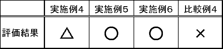
表2の結果から、図12A~図12C、図13A~図13C、及び図14A~図14Cで示した実施例4~6においては、前記光渦レーザビームが前記光吸収材に照射されたとき、レーザビームの光路内を飛翔していく前記光吸収材が観察できる。図15A~図15Cで示した比較例4においては、前記レーザビームが前記光吸収材に照射されたとき、拡散して飛翔していく前記光吸収材が観察できる。図12A~図14Cに示したように、前記光渦レーザビームの効果により前記光吸収材が拡散せずに飛翔するため、飛散が少ない安定したドット画像の形成が可能となる。
このように、実施例4~6において、前記光吸収材が直進性を持って飛翔することから、画像形成の分野及び立体造形物の製造分野においても十分応用が可能であると考えられる。 From the results in Table 2, in Examples 4 to 6 shown in FIGS. 12A to 12C, FIGS. 13A to 13C, and FIGS. 14A to 14C, The light absorbing material flying in the optical path of the laser beam can be observed. In Comparative Example 4 shown in FIGS. 15A to 15C, when the light absorbing material is irradiated with the laser beam, the light absorbing material that diffuses and flies can be observed. As shown in FIGS. 12A to 14C, since the light absorbing material flies without diffusing due to the effect of the optical vortex laser beam, it is possible to form a stable dot image with little scattering.
As described above, in Examples 4 to 6, since the light absorbing material flies straightly, it is considered that the light absorbing material can be sufficiently applied in the field of image formation and the field of manufacturing three-dimensional objects.
本発明の態様としては、例えば、以下のとおりである。
<1> 光を吸収する光吸収材と、
前記光吸収材の光吸収波長に対応する光渦レーザビームを前記光吸収材に照射し、前記光渦レーザビームのエネルギーにより前記光吸収材を前記光渦レーザビームの照射方向に飛翔させ、被付着物に付着させる光吸収材飛翔手段と、を有することを特徴とする光吸収材飛翔装置である。
<2> 前記光吸収材飛翔手段が、前記光を透過可能な光吸収材担持体の表面に担持された前記光吸収材に対し、前記光吸収材担持体の裏面から前記光渦レーザビームを照射する前記<1>に記載の光吸収材飛翔装置である。
<3> 前記光吸収材が、1Pa・s以上の粘度を有する前記<1>から<2>のいずれかに記載の光吸収材飛翔装置である。
<4> 前記光吸収材が光吸収物質を有し、前記光吸収物質における前記光の透過率が、70%以下である前記<1>から<3>のいずれかに記載の光吸収材飛翔装置である。
<5> 前記光吸収材担持体における前記光の透過率が、75%以上である前記<2>から<4>のいずれかに記載の光吸収材飛翔装置である。
<6> 前記光吸収材飛翔手段が、レーザビームを発生するレーザ光源と、前記レーザビームを前記光渦レーザビームに変換する光渦変換部とを有する前記<1>から<5>のいずれかに記載の光吸収材飛翔装置である。
<7> 前記光渦変換部が、螺旋状位相板である前記<6>に記載の光吸収材飛翔装置である。
<8> 前記光吸収材担持体が筒状であって、周方向に回転する前記光吸収材担持体の表面に前記光吸収材を供給する光吸収材供給手段を更に有する前記<2>から<7>のいずれかに記載の光吸収材飛翔装置である。
<9> 前記<1>から<8>のいずれかに記載の光吸収材飛翔装置を有し、
前記光吸収材が着色剤であることを特徴とする画像形成装置である。
<10> 前記<1>から<8>のいずれかに記載の光吸収材飛翔装置を有し、
前記光吸収材が立体造形剤であり、
前記光吸収材飛翔手段が、前記立体造形剤を前記被付着物に対して立体的に付着させることを特徴とする立体造形物の製造装置である。
<11> 光を吸収する光吸収材に、前記光吸収材の光吸収波長に対応する光渦レーザビームを照射し、前記光渦レーザビームのエネルギーにより前記光吸収材を前記光渦レーザビームの照射方向に飛翔させ、被付着物に付着させる光吸収材飛翔工程を含むことを特徴とする光吸収材飛翔方法である。
<12> 前記<11>に記載の光吸収材飛翔方法を含み、
前記光吸収材が着色剤であることを特徴とする画像形成方法である。
<13> 前記<11>に記載の光吸収材飛翔方法を含み、
前記光吸収材が立体造形剤であり、
前記光吸収材飛翔工程が、前記立体造形剤を前記被付着物に対して立体的に付着させる立体造形剤飛翔工程であることを特徴とする立体造形物の製造方法である。 As an aspect of this invention, it is as follows, for example.
<1> a light absorbing material that absorbs light;
The light absorbing material is irradiated with an optical vortex laser beam corresponding to the light absorption wavelength of the light absorbing material, and the light absorbing material is caused to fly in the irradiation direction of the optical vortex laser beam by the energy of the optical vortex laser beam. A light absorbing material flying device comprising: a light absorbing material flying means for adhering to a deposit.
<2> The light eddy laser beam is emitted from the back surface of the light absorbing material carrier to the light absorbing material carried on the surface of the light absorbing material carrier capable of transmitting the light. The light absorbing material flying device according to <1>, wherein irradiation is performed.
<3> The light absorbing material flying device according to any one of <1> to <2>, wherein the light absorbing material has a viscosity of 1 Pa · s or more.
<4> The light absorbing material flying according to any one of <1> to <3>, wherein the light absorbing material includes a light absorbing material, and the light transmittance of the light absorbing material is 70% or less. Device.
<5> The light absorbing material flying device according to any one of <2> to <4>, wherein the light transmittance of the light absorbing material carrier is 75% or more.
<6> Any one of the items <1> to <5>, wherein the light absorbing material flying means includes a laser light source that generates a laser beam and an optical vortex conversion unit that converts the laser beam into the optical vortex laser beam. The light absorbing material flying device according toclaim 1.
<7> The light absorbing material flying device according to <6>, wherein the optical vortex converter is a spiral phase plate.
<8> From the above <2>, wherein the light absorbing material carrier is cylindrical, and further includes a light absorbing material supply means for supplying the light absorbing material to the surface of the light absorbing material carrier that rotates in the circumferential direction. <7> The light absorbing material flying device according to any one of the above.
<9> The light absorbing material flying device according to any one of <1> to <8>,
In the image forming apparatus, the light absorbing material is a colorant.
<10> The light absorbing material flying device according to any one of <1> to <8>,
The light absorbing material is a three-dimensional modeling agent,
The light-absorbing material flying unit causes the three-dimensional modeling agent to three-dimensionally adhere to the adherend.
<11> A light absorbing material that absorbs light is irradiated with a light vortex laser beam corresponding to a light absorption wavelength of the light absorbing material, and the light absorbing material is irradiated with the energy of the light vortex laser beam. A light absorbing material flying method including a light absorbing material flying step of flying in an irradiation direction and attaching to an adherend.
<12> including the light absorber flying method according to <11>,
In the image forming method, the light absorbing material is a colorant.
<13> The light absorber flying method according to <11>,
The light absorbing material is a three-dimensional modeling agent,
The light-absorbing material flying step is a three-dimensional modeling agent flying step in which the three-dimensional modeling agent is three-dimensionally attached to the adherend.
<1> 光を吸収する光吸収材と、
前記光吸収材の光吸収波長に対応する光渦レーザビームを前記光吸収材に照射し、前記光渦レーザビームのエネルギーにより前記光吸収材を前記光渦レーザビームの照射方向に飛翔させ、被付着物に付着させる光吸収材飛翔手段と、を有することを特徴とする光吸収材飛翔装置である。
<2> 前記光吸収材飛翔手段が、前記光を透過可能な光吸収材担持体の表面に担持された前記光吸収材に対し、前記光吸収材担持体の裏面から前記光渦レーザビームを照射する前記<1>に記載の光吸収材飛翔装置である。
<3> 前記光吸収材が、1Pa・s以上の粘度を有する前記<1>から<2>のいずれかに記載の光吸収材飛翔装置である。
<4> 前記光吸収材が光吸収物質を有し、前記光吸収物質における前記光の透過率が、70%以下である前記<1>から<3>のいずれかに記載の光吸収材飛翔装置である。
<5> 前記光吸収材担持体における前記光の透過率が、75%以上である前記<2>から<4>のいずれかに記載の光吸収材飛翔装置である。
<6> 前記光吸収材飛翔手段が、レーザビームを発生するレーザ光源と、前記レーザビームを前記光渦レーザビームに変換する光渦変換部とを有する前記<1>から<5>のいずれかに記載の光吸収材飛翔装置である。
<7> 前記光渦変換部が、螺旋状位相板である前記<6>に記載の光吸収材飛翔装置である。
<8> 前記光吸収材担持体が筒状であって、周方向に回転する前記光吸収材担持体の表面に前記光吸収材を供給する光吸収材供給手段を更に有する前記<2>から<7>のいずれかに記載の光吸収材飛翔装置である。
<9> 前記<1>から<8>のいずれかに記載の光吸収材飛翔装置を有し、
前記光吸収材が着色剤であることを特徴とする画像形成装置である。
<10> 前記<1>から<8>のいずれかに記載の光吸収材飛翔装置を有し、
前記光吸収材が立体造形剤であり、
前記光吸収材飛翔手段が、前記立体造形剤を前記被付着物に対して立体的に付着させることを特徴とする立体造形物の製造装置である。
<11> 光を吸収する光吸収材に、前記光吸収材の光吸収波長に対応する光渦レーザビームを照射し、前記光渦レーザビームのエネルギーにより前記光吸収材を前記光渦レーザビームの照射方向に飛翔させ、被付着物に付着させる光吸収材飛翔工程を含むことを特徴とする光吸収材飛翔方法である。
<12> 前記<11>に記載の光吸収材飛翔方法を含み、
前記光吸収材が着色剤であることを特徴とする画像形成方法である。
<13> 前記<11>に記載の光吸収材飛翔方法を含み、
前記光吸収材が立体造形剤であり、
前記光吸収材飛翔工程が、前記立体造形剤を前記被付着物に対して立体的に付着させる立体造形剤飛翔工程であることを特徴とする立体造形物の製造方法である。 As an aspect of this invention, it is as follows, for example.
<1> a light absorbing material that absorbs light;
The light absorbing material is irradiated with an optical vortex laser beam corresponding to the light absorption wavelength of the light absorbing material, and the light absorbing material is caused to fly in the irradiation direction of the optical vortex laser beam by the energy of the optical vortex laser beam. A light absorbing material flying device comprising: a light absorbing material flying means for adhering to a deposit.
<2> The light eddy laser beam is emitted from the back surface of the light absorbing material carrier to the light absorbing material carried on the surface of the light absorbing material carrier capable of transmitting the light. The light absorbing material flying device according to <1>, wherein irradiation is performed.
<3> The light absorbing material flying device according to any one of <1> to <2>, wherein the light absorbing material has a viscosity of 1 Pa · s or more.
<4> The light absorbing material flying according to any one of <1> to <3>, wherein the light absorbing material includes a light absorbing material, and the light transmittance of the light absorbing material is 70% or less. Device.
<5> The light absorbing material flying device according to any one of <2> to <4>, wherein the light transmittance of the light absorbing material carrier is 75% or more.
<6> Any one of the items <1> to <5>, wherein the light absorbing material flying means includes a laser light source that generates a laser beam and an optical vortex conversion unit that converts the laser beam into the optical vortex laser beam. The light absorbing material flying device according to
<7> The light absorbing material flying device according to <6>, wherein the optical vortex converter is a spiral phase plate.
<8> From the above <2>, wherein the light absorbing material carrier is cylindrical, and further includes a light absorbing material supply means for supplying the light absorbing material to the surface of the light absorbing material carrier that rotates in the circumferential direction. <7> The light absorbing material flying device according to any one of the above.
<9> The light absorbing material flying device according to any one of <1> to <8>,
In the image forming apparatus, the light absorbing material is a colorant.
<10> The light absorbing material flying device according to any one of <1> to <8>,
The light absorbing material is a three-dimensional modeling agent,
The light-absorbing material flying unit causes the three-dimensional modeling agent to three-dimensionally adhere to the adherend.
<11> A light absorbing material that absorbs light is irradiated with a light vortex laser beam corresponding to a light absorption wavelength of the light absorbing material, and the light absorbing material is irradiated with the energy of the light vortex laser beam. A light absorbing material flying method including a light absorbing material flying step of flying in an irradiation direction and attaching to an adherend.
<12> including the light absorber flying method according to <11>,
In the image forming method, the light absorbing material is a colorant.
<13> The light absorber flying method according to <11>,
The light absorbing material is a three-dimensional modeling agent,
The light-absorbing material flying step is a three-dimensional modeling agent flying step in which the three-dimensional modeling agent is three-dimensionally attached to the adherend.
1 光吸収材飛翔手段
2 レーザ光源
3 ビーム径変更手段
4 ビーム波長変更手段
5 光渦変換部
6 エネルギー調整フィルタ
11 レーザビーム
12 光渦レーザビーム
20 光吸収材
21 着色剤
22 立体造形剤
30 被付着物
31 記録媒体
32 基板
40 光吸収材担持体
100 光吸収材飛翔ユニット
110 着色剤飛翔ユニット
120 立体造形剤飛翔ユニット
124 立体造形物
130 立体造形ヘッドユニット
300~307 光吸収材飛翔装置
400、401 画像形成装置
500 立体造形物の製造装置 DESCRIPTION OFSYMBOLS 1 Light absorber flying means 2 Laser light source 3 Beam diameter change means 4 Beam wavelength change means 5 Optical vortex conversion part 6 Energy adjustment filter 11 Laser beam 12 Optical vortex laser beam 20 Light absorber 21 Colorant 22 Three-dimensional modeling agent 30 Attachment Kimono 31 Recording medium 32 Substrate 40 Light absorber carrying body 100 Light absorber flying unit 110 Colorant flying unit 120 Three-dimensional modeling agent flying unit 124 Three-dimensional modeling 130 Three-dimensional modeling head unit 300 to 307 Light absorbing material flying device 400, 401 image Forming apparatus 500 Three-dimensional structure manufacturing apparatus
2 レーザ光源
3 ビーム径変更手段
4 ビーム波長変更手段
5 光渦変換部
6 エネルギー調整フィルタ
11 レーザビーム
12 光渦レーザビーム
20 光吸収材
21 着色剤
22 立体造形剤
30 被付着物
31 記録媒体
32 基板
40 光吸収材担持体
100 光吸収材飛翔ユニット
110 着色剤飛翔ユニット
120 立体造形剤飛翔ユニット
124 立体造形物
130 立体造形ヘッドユニット
300~307 光吸収材飛翔装置
400、401 画像形成装置
500 立体造形物の製造装置 DESCRIPTION OF
Claims (13)
- 光を吸収する光吸収材と、
前記光吸収材の光吸収波長に対応する光渦レーザビームを前記光吸収材に照射し、前記光渦レーザビームのエネルギーにより前記光吸収材を前記光渦レーザビームの照射方向に飛翔させ、被付着物に付着させる光吸収材飛翔手段と、を有することを特徴とする光吸収材飛翔装置。 A light absorbing material that absorbs light;
The light absorbing material is irradiated with an optical vortex laser beam corresponding to the light absorption wavelength of the light absorbing material, and the light absorbing material is caused to fly in the irradiation direction of the optical vortex laser beam by the energy of the optical vortex laser beam. A light absorbing material flying means for adhering to a deposit. - 前記光吸収材飛翔手段が、前記光を透過可能な光吸収材担持体の表面に担持された前記光吸収材に対し、前記光吸収材担持体の裏面から前記光渦レーザビームを照射する請求項1に記載の光吸収材飛翔装置。 The light absorbing material flying means irradiates the optical vortex laser beam from the back surface of the light absorbing material carrier to the light absorbing material carried on the surface of the light absorbing material carrier capable of transmitting the light. Item 4. The light absorber flying device according to Item 1.
- 前記光吸収材が、1Pa・s以上の粘度を有する請求項1から2のいずれかに記載の光吸収材飛翔装置。 The light absorbing material flying device according to claim 1, wherein the light absorbing material has a viscosity of 1 Pa · s or more.
- 前記光吸収材が光吸収物質を有し、前記光吸収物質における前記光の透過率が、70%以下である請求項1から3のいずれかに記載の光吸収材飛翔装置。 The light absorbing material flying device according to any one of claims 1 to 3, wherein the light absorbing material includes a light absorbing material, and the light transmittance of the light absorbing material is 70% or less.
- 前記光吸収材担持体における前記光の透過率が、75%以上である請求項2から4のいずれかに記載の光吸収材飛翔装置。 The light absorber flying device according to any one of claims 2 to 4, wherein the light transmittance of the light absorber support is 75% or more.
- 前記光吸収材飛翔手段が、レーザビームを発生するレーザ光源と、前記レーザビームを前記光渦レーザビームに変換する光渦変換部とを有する請求項1から5のいずれかに記載の光吸収材飛翔装置。 The light absorbing material according to claim 1, wherein the light absorbing material flying means includes a laser light source that generates a laser beam, and an optical vortex converter that converts the laser beam into the optical vortex laser beam. Flying device.
- 前記光渦変換部が、螺旋状位相板である請求項6に記載の光吸収材飛翔装置。 The light absorbing material flying device according to claim 6, wherein the optical vortex converter is a spiral phase plate.
- 前記光吸収材担持体が筒状であって、周方向に回転する前記光吸収材担持体の表面に前記光吸収材を供給する光吸収材供給手段を更に有する請求項2から7のいずれかに記載の光吸収材飛翔装置。 8. The light absorption material supply means according to claim 2, further comprising a light absorption material supply means for supplying the light absorption material to a surface of the light absorption material support rotating in the circumferential direction. The light absorbing material flying device according to 1.
- 請求項1から8のいずれかに記載の光吸収材飛翔装置を有し、
前記光吸収材が着色剤であることを特徴とする画像形成装置。 The light absorbing material flying device according to any one of claims 1 to 8,
An image forming apparatus, wherein the light absorbing material is a colorant. - 請求項1から8のいずれかに記載の光吸収材飛翔装置を有し、
前記光吸収材が立体造形剤であり、
前記光吸収材飛翔手段が、前記立体造形剤を前記被付着物に対して立体的に付着させることを特徴とする立体造形物の製造装置。 The light absorbing material flying device according to any one of claims 1 to 8,
The light absorbing material is a three-dimensional modeling agent,
The apparatus for manufacturing a three-dimensional structure, wherein the light absorbing material flying means causes the three-dimensional structure forming agent to three-dimensionally adhere to the adherend. - 光を吸収する光吸収材に、前記光吸収材の光吸収波長に対応する光渦レーザビームを照射し、前記光渦レーザビームのエネルギーにより前記光吸収材を前記光渦レーザビームの照射方向に飛翔させ、被付着物に付着させる光吸収材飛翔工程を含むことを特徴とする光吸収材飛翔方法。 A light absorbing material that absorbs light is irradiated with an optical vortex laser beam corresponding to the light absorption wavelength of the light absorbing material, and the light absorbing material is irradiated in the irradiation direction of the optical vortex laser beam by the energy of the optical vortex laser beam. A light absorbing material flying method comprising: a light absorbing material flying step of flying and adhering to an adherend.
- 請求項11に記載の光吸収材飛翔方法を含み、
前記光吸収材が着色剤であることを特徴とする画像形成方法。 A light absorbing material flying method according to claim 11,
An image forming method, wherein the light absorbing material is a colorant. - 請求項11に記載の光吸収材飛翔方法を含み、
前記光吸収材が立体造形剤であり、
前記光吸収材飛翔工程が、前記立体造形剤を前記被付着物に対して立体的に付着させる立体造形剤飛翔工程であることを特徴とする立体造形物の製造方法。 A light absorbing material flying method according to claim 11,
The light absorbing material is a three-dimensional modeling agent,
The manufacturing method of a three-dimensional modeled object, wherein the light absorbing material flying step is a three-dimensional model agent flying process in which the three-dimensional model agent is three-dimensionally attached to the adherend.
Priority Applications (4)
| Application Number | Priority Date | Filing Date | Title |
|---|---|---|---|
| CN201680011875.9A CN107635779B (en) | 2015-02-25 | 2016-02-23 | light absorbing material spraying apparatus, light absorbing material spraying method, and application using the same |
| EP16755466.6A EP3263339B1 (en) | 2015-02-25 | 2016-02-23 | Light-absorbing material jetting device, light-absorbing material jetting method, and applications using same |
| JP2017502375A JP6455588B2 (en) | 2015-02-25 | 2016-02-23 | Light absorber flying device, light absorber flying method, and application using the same |
| US15/682,725 US10427322B2 (en) | 2015-02-25 | 2017-08-22 | Light-absorbing material flying apparatus, method for flying light-absorbing material, and applications using same |
Applications Claiming Priority (4)
| Application Number | Priority Date | Filing Date | Title |
|---|---|---|---|
| JP2015-034707 | 2015-02-25 | ||
| JP2015034707 | 2015-02-25 | ||
| JP2016-024079 | 2016-02-10 | ||
| JP2016024079 | 2016-02-10 |
Related Child Applications (1)
| Application Number | Title | Priority Date | Filing Date |
|---|---|---|---|
| US15/682,725 Continuation US10427322B2 (en) | 2015-02-25 | 2017-08-22 | Light-absorbing material flying apparatus, method for flying light-absorbing material, and applications using same |
Publications (1)
| Publication Number | Publication Date |
|---|---|
| WO2016136722A1 true WO2016136722A1 (en) | 2016-09-01 |
Family
ID=56788558
Family Applications (1)
| Application Number | Title | Priority Date | Filing Date |
|---|---|---|---|
| PCT/JP2016/055208 WO2016136722A1 (en) | 2015-02-25 | 2016-02-23 | Light-absorbing material jetting device, light-absorbing material jetting method, and applications using same |
Country Status (5)
| Country | Link |
|---|---|
| US (1) | US10427322B2 (en) |
| EP (1) | EP3263339B1 (en) |
| JP (1) | JP6455588B2 (en) |
| CN (1) | CN107635779B (en) |
| WO (1) | WO2016136722A1 (en) |
Cited By (11)
| Publication number | Priority date | Publication date | Assignee | Title |
|---|---|---|---|---|
| WO2017061499A1 (en) * | 2015-10-06 | 2017-04-13 | 株式会社リコー | Image-forming method, image-forming apparatus, laser irradiation printing ink, and method for manufacturing object with formed image |
| JP2019123133A (en) * | 2018-01-16 | 2019-07-25 | 株式会社リコー | Light absorbing material flying device, light absorbing material flying method, and applications using the same |
| WO2020184525A1 (en) | 2019-03-08 | 2020-09-17 | Ricoh Company, Ltd. | Apparatus configured to model three-dimensional modeled object, apparatus configured to fly particles, and method of modeling three-dimensional modeled object |
| JP2021054042A (en) * | 2019-03-08 | 2021-04-08 | 株式会社リコー | Apparatus for modeling three-dimensional modeled article, apparatus for flying particle, and method for modeling three-dimensional modeled article |
| US11094517B2 (en) | 2019-03-20 | 2021-08-17 | Ricoh Company, Ltd. | Method and device for preparing measurement sample for MALDI mass spectrometry, measurement sample for MALDI mass spectrometry, MALDI mass spectrometry method, and non-transitory recording medium for preparing measurement sample for MALDI mass spectrometry |
| EP3868544A1 (en) | 2020-02-19 | 2021-08-25 | Ricoh Company, Ltd. | Three-dimensional modeling apparatus and three-dimensional modeling method |
| JP2021151772A (en) * | 2020-03-23 | 2021-09-30 | 株式会社リコー | Flying body generation method, flying body generation apparatus and image formation method |
| EP3939789A2 (en) | 2020-05-27 | 2022-01-19 | Ricoh Company, Ltd. | Light irradiation method, light absorbing material attaching apparatus, flying body generating method and apparatus, image forming method, and three-dimensional object producing method |
| WO2022113607A1 (en) | 2020-11-30 | 2022-06-02 | Ricoh Company, Ltd. | Flying body generating method and flying body generating apparatus, image forming apparatus, and three-dimensional object producing apparatus |
| JP2022536611A (en) * | 2019-06-12 | 2022-08-18 | フィールドポイント (キプロス) リミテッド | Optical Filter Based on Light-Matter Coupling in Quantum Confined Cavity Space |
| KR102656070B1 (en) | 2019-06-12 | 2024-04-09 | 필드포인트 (사이프러스) 리미티드 | Optical filters based on light-matter coupling in quantum-confined cavity space |
Families Citing this family (7)
| Publication number | Priority date | Publication date | Assignee | Title |
|---|---|---|---|---|
| US10393643B2 (en) | 2016-09-07 | 2019-08-27 | Rochester Institute Of Technology | Optical vortex coronagraph scatterometer |
| TWI651906B (en) * | 2018-06-08 | 2019-02-21 | 國立中山大學 | Vortex laser generation device in degenerate cavity with spiral phase element and vortex laser generation method |
| US10807311B2 (en) | 2018-09-10 | 2020-10-20 | Rebecca Metcalf | Additive manufacturing device with IR targeting and related methods |
| JP7287124B2 (en) | 2019-06-03 | 2023-06-06 | 株式会社リコー | Apparatus for flying light-absorbing material, apparatus for forming three-dimensional object, method for flying light-absorbing material |
| EP3886141A1 (en) * | 2020-03-23 | 2021-09-29 | Ricoh Company, Ltd. | Method, device, and base for preparing measurement sample for maldi mass spectrometry |
| US11532472B2 (en) * | 2020-07-30 | 2022-12-20 | Ricoh Company, Ltd. | Mass spectrometry |
| CN114769623B (en) * | 2022-06-20 | 2022-09-02 | 吉林大学 | Preparation method for manufacturing NiTi alloy super-hydrophilic surface by additive manufacturing |
Citations (8)
| Publication number | Priority date | Publication date | Assignee | Title |
|---|---|---|---|---|
| JPS62184860A (en) * | 1986-02-10 | 1987-08-13 | Toshiba Corp | Ink jet recorder |
| JPS62191157A (en) * | 1986-02-17 | 1987-08-21 | Toshiba Corp | Recording apparatus using thermal ink jet system |
| JPH11245416A (en) * | 1998-03-03 | 1999-09-14 | Fuji Xerox Co Ltd | Ink-jet recording apparatus |
| JP2005518965A (en) * | 2002-03-07 | 2005-06-30 | オウレンタム イノベーションズ テクノロジエン ゲーエムベーハー | High quality printing process and printing equipment, and printing materials |
| JP2008193066A (en) * | 2007-01-09 | 2008-08-21 | Chiba Univ | Optical vortex laser beam oscillation method and optical vortex laser beam oscillation apparatus |
| JP2010247230A (en) * | 2009-03-27 | 2010-11-04 | Chiba Univ | Laser beam machining method, laser beam machining method using circularly polarizing/optical vortex laser beam, manufacturing method of acicular member, and acicular member |
| JP2012182257A (en) * | 2011-02-28 | 2012-09-20 | Chiba Univ | Optical vortex laser beam oscillation apparatus and oscillation method |
| WO2012169578A2 (en) * | 2011-06-07 | 2012-12-13 | 国立大学法人 千葉大学 | Optical vortex laser vibration method and optical vortex laser vibration device |
Family Cites Families (12)
| Publication number | Priority date | Publication date | Assignee | Title |
|---|---|---|---|---|
| JPS61118273A (en) | 1984-11-15 | 1986-06-05 | Erumu:Kk | Laser type ink jet printer |
| DE3702643A1 (en) | 1986-02-10 | 1987-08-13 | Toshiba Kawasaki Kk | INK NIBLE PEN AND WRITING HEAD AND WRITING HEAD CASSETTE DAFUER |
| JPH01101157A (en) | 1987-10-15 | 1989-04-19 | Ricoh Co Ltd | Nonimpact printer |
| JP3081222B2 (en) | 1990-09-21 | 2000-08-28 | 株式会社リコー | Ink flight recording method and apparatus |
| JP3179834B2 (en) | 1991-07-19 | 2001-06-25 | 株式会社リコー | Liquid flight recorder |
| JPH08118795A (en) * | 1994-10-21 | 1996-05-14 | Sony Corp | Recording method, recorder and recording material composition |
| JPH09169111A (en) | 1995-12-20 | 1997-06-30 | Brother Ind Ltd | Ink jet printer |
| JPH11138773A (en) | 1997-11-10 | 1999-05-25 | Fuji Xerox Co Ltd | Method and device for image forming |
| JP4541523B2 (en) * | 2000-10-10 | 2010-09-08 | キヤノン株式会社 | Multi-beam optical scanning optical system, multi-beam optical scanning device, and image forming apparatus |
| US7390704B2 (en) * | 2004-06-16 | 2008-06-24 | Semiconductor Energy Laboratory Co., Ltd. | Laser process apparatus, laser irradiation method, and method for manufacturing semiconductor device |
| KR101884397B1 (en) * | 2012-10-24 | 2018-08-02 | 에이치피프린팅코리아 주식회사 | Laser scanning unit and image forming apparatus employing the same |
| US10099921B2 (en) | 2013-05-10 | 2018-10-16 | National University Corporation Chiba University | Method for producing organic helical structure, and organic helical structure produced using said method |
-
2016
- 2016-02-23 JP JP2017502375A patent/JP6455588B2/en active Active
- 2016-02-23 EP EP16755466.6A patent/EP3263339B1/en active Active
- 2016-02-23 CN CN201680011875.9A patent/CN107635779B/en active Active
- 2016-02-23 WO PCT/JP2016/055208 patent/WO2016136722A1/en active Application Filing
-
2017
- 2017-08-22 US US15/682,725 patent/US10427322B2/en active Active
Patent Citations (8)
| Publication number | Priority date | Publication date | Assignee | Title |
|---|---|---|---|---|
| JPS62184860A (en) * | 1986-02-10 | 1987-08-13 | Toshiba Corp | Ink jet recorder |
| JPS62191157A (en) * | 1986-02-17 | 1987-08-21 | Toshiba Corp | Recording apparatus using thermal ink jet system |
| JPH11245416A (en) * | 1998-03-03 | 1999-09-14 | Fuji Xerox Co Ltd | Ink-jet recording apparatus |
| JP2005518965A (en) * | 2002-03-07 | 2005-06-30 | オウレンタム イノベーションズ テクノロジエン ゲーエムベーハー | High quality printing process and printing equipment, and printing materials |
| JP2008193066A (en) * | 2007-01-09 | 2008-08-21 | Chiba Univ | Optical vortex laser beam oscillation method and optical vortex laser beam oscillation apparatus |
| JP2010247230A (en) * | 2009-03-27 | 2010-11-04 | Chiba Univ | Laser beam machining method, laser beam machining method using circularly polarizing/optical vortex laser beam, manufacturing method of acicular member, and acicular member |
| JP2012182257A (en) * | 2011-02-28 | 2012-09-20 | Chiba Univ | Optical vortex laser beam oscillation apparatus and oscillation method |
| WO2012169578A2 (en) * | 2011-06-07 | 2012-12-13 | 国立大学法人 千葉大学 | Optical vortex laser vibration method and optical vortex laser vibration device |
Cited By (16)
| Publication number | Priority date | Publication date | Assignee | Title |
|---|---|---|---|---|
| WO2017061499A1 (en) * | 2015-10-06 | 2017-04-13 | 株式会社リコー | Image-forming method, image-forming apparatus, laser irradiation printing ink, and method for manufacturing object with formed image |
| US10603925B2 (en) | 2015-10-06 | 2020-03-31 | Ricoh Company, Ltd. | Image-forming method, image-forming apparatus, laser irradiation printing ink, and method for manufacturing object with formed image |
| JP2019123133A (en) * | 2018-01-16 | 2019-07-25 | 株式会社リコー | Light absorbing material flying device, light absorbing material flying method, and applications using the same |
| JP7424093B2 (en) | 2019-03-08 | 2024-01-30 | 株式会社リコー | Devices for printing 3D objects, methods for printing 3D objects |
| JP2021054042A (en) * | 2019-03-08 | 2021-04-08 | 株式会社リコー | Apparatus for modeling three-dimensional modeled article, apparatus for flying particle, and method for modeling three-dimensional modeled article |
| WO2020184525A1 (en) | 2019-03-08 | 2020-09-17 | Ricoh Company, Ltd. | Apparatus configured to model three-dimensional modeled object, apparatus configured to fly particles, and method of modeling three-dimensional modeled object |
| US11094517B2 (en) | 2019-03-20 | 2021-08-17 | Ricoh Company, Ltd. | Method and device for preparing measurement sample for MALDI mass spectrometry, measurement sample for MALDI mass spectrometry, MALDI mass spectrometry method, and non-transitory recording medium for preparing measurement sample for MALDI mass spectrometry |
| JP2022536611A (en) * | 2019-06-12 | 2022-08-18 | フィールドポイント (キプロス) リミテッド | Optical Filter Based on Light-Matter Coupling in Quantum Confined Cavity Space |
| JP7318167B2 (en) | 2019-06-12 | 2023-08-01 | フィールドポイント (キプロス) リミテッド | Optical Filter Based on Light-Matter Coupling in Quantum Confined Cavity Space |
| KR102656070B1 (en) | 2019-06-12 | 2024-04-09 | 필드포인트 (사이프러스) 리미티드 | Optical filters based on light-matter coupling in quantum-confined cavity space |
| EP3868544A1 (en) | 2020-02-19 | 2021-08-25 | Ricoh Company, Ltd. | Three-dimensional modeling apparatus and three-dimensional modeling method |
| US11958242B2 (en) | 2020-02-19 | 2024-04-16 | Ricoh Company, Ltd. | Three-dimensional modeling apparatus and three-dimensional modeling method |
| JP2021151772A (en) * | 2020-03-23 | 2021-09-30 | 株式会社リコー | Flying body generation method, flying body generation apparatus and image formation method |
| JP7442146B2 (en) | 2020-03-23 | 2024-03-04 | 株式会社リコー | Flying object generation method, flying object generating device, and image forming method |
| EP3939789A2 (en) | 2020-05-27 | 2022-01-19 | Ricoh Company, Ltd. | Light irradiation method, light absorbing material attaching apparatus, flying body generating method and apparatus, image forming method, and three-dimensional object producing method |
| WO2022113607A1 (en) | 2020-11-30 | 2022-06-02 | Ricoh Company, Ltd. | Flying body generating method and flying body generating apparatus, image forming apparatus, and three-dimensional object producing apparatus |
Also Published As
| Publication number | Publication date |
|---|---|
| EP3263339A4 (en) | 2018-04-18 |
| CN107635779B (en) | 2019-12-13 |
| CN107635779A (en) | 2018-01-26 |
| US20170348872A1 (en) | 2017-12-07 |
| JP6455588B2 (en) | 2019-01-23 |
| US10427322B2 (en) | 2019-10-01 |
| JPWO2016136722A1 (en) | 2018-01-11 |
| EP3263339B1 (en) | 2019-11-06 |
| EP3263339A1 (en) | 2018-01-03 |
Similar Documents
| Publication | Publication Date | Title |
|---|---|---|
| JP6455588B2 (en) | Light absorber flying device, light absorber flying method, and application using the same | |
| US8820911B2 (en) | Coating apparatus and image forming apparatus | |
| KR102385592B1 (en) | An optical device that produces flicker-like optical effects | |
| US20160097996A1 (en) | Foil printing | |
| JP2012061852A (en) | Method of forming image on substrate with ink partial-curing and contact leveling and apparatus useful in forming image on substrate | |
| US20210370702A1 (en) | Light irradiation method, light absorbing material attaching apparatus, flying body generating method and apparatus, image forming method, and three-dimensional object producing method | |
| CN100390573C (en) | Manufacturing method of light quantity regulating structural element, light quantity regulating structural element, light quantity regulating device and photographic device | |
| US20200298440A1 (en) | Method for forming flying object using optical vortex laser, and image forming method and apparatus | |
| CN103529668B (en) | Overcoat compositions, electrophotographic image forming method and electrophotographic imaging forming apparatus for electrofax | |
| CN107710077A (en) | Recorded matter and image forming method | |
| JP6095537B2 (en) | Marking materials for laser glazing systems and methods | |
| JP2010089505A (en) | Imaging system | |
| CN111320896B (en) | Active ray-curable ink and image forming method | |
| JP6973097B2 (en) | Light-absorbing material flying device and light-absorbing material flying method, and applications using them | |
| JP2021187143A (en) | Light irradiation method, apparatus for attaching light absorbing material, flying body generating method and apparatus, image forming method, and three-dimensional object producing method | |
| JP2023033176A (en) | Flying object generation method, flying object transfer method and image formation apparatus | |
| JP7442146B2 (en) | Flying object generation method, flying object generating device, and image forming method | |
| WO2022113607A1 (en) | Flying body generating method and flying body generating apparatus, image forming apparatus, and three-dimensional object producing apparatus | |
| JP2022086606A (en) | Flying object generation device, image formation device, solid molding manufacturing apparatus, flying object generation method, and substrate for light absorption material flying | |
| JP2020157751A (en) | Flying object generation method using optical vortex laser, image formation method and apparatus | |
| JP2023001024A (en) | Flying substance transfer method, flying substance transfer device, image formation method, method of manufacturing three-dimensional molding, and crystal manufacturing method | |
| JP2022026065A (en) | Flying object generation device, image formation device, manufacturing method of three-dimensional shaped article, and flying object generation method | |
| JP2023000527A (en) | Flying body transfer method, flying body transfer apparatus, image formation method, and three-dimensional object manufacturing method | |
| JP2003084578A (en) | Image forming method and image forming apparatus | |
| JP2014205813A (en) | Porous flexible sheet, and production method and device thereof |
Legal Events
| Date | Code | Title | Description |
|---|---|---|---|
| 121 | Ep: the epo has been informed by wipo that ep was designated in this application |
Ref document number: 16755466 Country of ref document: EP Kind code of ref document: A1 |
|
| ENP | Entry into the national phase |
Ref document number: 2017502375 Country of ref document: JP Kind code of ref document: A |
|
| NENP | Non-entry into the national phase |
Ref country code: DE |
|
| REEP | Request for entry into the european phase |
Ref document number: 2016755466 Country of ref document: EP |