EP3868517B1 - Klettermaschine und bewegungsverfahren dafür - Google Patents
Klettermaschine und bewegungsverfahren dafür Download PDFInfo
- Publication number
- EP3868517B1 EP3868517B1 EP20191275.5A EP20191275A EP3868517B1 EP 3868517 B1 EP3868517 B1 EP 3868517B1 EP 20191275 A EP20191275 A EP 20191275A EP 3868517 B1 EP3868517 B1 EP 3868517B1
- Authority
- EP
- European Patent Office
- Prior art keywords
- machine body
- suspension mechanism
- rope
- suspension
- object structure
- Prior art date
- Legal status (The legal status is an assumption and is not a legal conclusion. Google has not performed a legal analysis and makes no representation as to the accuracy of the status listed.)
- Active
Links
Images




Classifications
-
- B—PERFORMING OPERATIONS; TRANSPORTING
- B62—LAND VEHICLES FOR TRAVELLING OTHERWISE THAN ON RAILS
- B62D—MOTOR VEHICLES; TRAILERS
- B62D57/00—Vehicles characterised by having other propulsion or other ground- engaging means than wheels or endless track, alone or in addition to wheels or endless track
- B62D57/02—Vehicles characterised by having other propulsion or other ground- engaging means than wheels or endless track, alone or in addition to wheels or endless track with ground-engaging propulsion means, e.g. walking members
- B62D57/024—Vehicles characterised by having other propulsion or other ground- engaging means than wheels or endless track, alone or in addition to wheels or endless track with ground-engaging propulsion means, e.g. walking members specially adapted for moving on inclined or vertical surfaces
-
- B—PERFORMING OPERATIONS; TRANSPORTING
- B25—HAND TOOLS; PORTABLE POWER-DRIVEN TOOLS; MANIPULATORS
- B25J—MANIPULATORS; CHAMBERS PROVIDED WITH MANIPULATION DEVICES
- B25J11/00—Manipulators not otherwise provided for
-
- B—PERFORMING OPERATIONS; TRANSPORTING
- B25—HAND TOOLS; PORTABLE POWER-DRIVEN TOOLS; MANIPULATORS
- B25J—MANIPULATORS; CHAMBERS PROVIDED WITH MANIPULATION DEVICES
- B25J5/00—Manipulators mounted on wheels or on carriages
Definitions
- the present invention pertains to the field of complex-structure moving technologies, and in particular, to a climbing machine and a moving method therefor.
- Climbing robots are important high-altitude special robots.
- a detection robot for a large road/bridge or a large oil tank or a large ship needs a mechanism that can climb and move on a wall surface, and a detection instrument is mounted on the climbing robot.
- the climbing robot is usually mounted with a suction mechanism.
- a suction force is generated between the suction mechanism and the wall surface, and the suction force causes a friction force between the robot and the wall surface.
- the friction force overcomes the gravity of the robot and further provides a driving force for the robot to move.
- the suction mechanism usually uses vacuum suction or magnetic suction.
- An object surface under suction needs to be a complete surface regardless of whether the robot uses vacuum suction or magnetic suction.
- the object surface under suction is a hollow surface, for example, a wire mesh, a steel frame, or a wooden fence, clearly, serious vacuum leakage occurs in vacuum suction, and there is no sufficient suction area for a magnetic suction mechanism to generate an enough magnetic force.
- a climbed object is not a plane but a structure with a complex shape, for example, a bending surface with a surface M and a surface N
- an existing vertical facade mobile robot (a wheel-driven structure) cannot move from the surface M to the surface N, because the suction force of the suction mechanism becomes invalid in a process of moving from the surface M to the surface N.
- the suction mechanism cannot adhere to the object surface, which causes a suction failure.
- a multi-joint multi-legged robot can cross a bending surface.
- it is very difficult to design such a robot as the multi-joint multi-legged design makes a robot mechanism very complex.
- many joint motors are needed, which greatly increases the robot weight.
- An increase of the robot weight is very detrimental to climbing a vertical facade, imposes a high requirement on the suction force of the suction mechanism, and raises a falling risk.
- JP 2008 260436 A discloses a robot body comprising an extension type arm, a tether type arm; a mobile extension type arm extending unit for controlling the extension and storage of the extension type arm; a tether extension unit for controlling the extension and storage of the tether type arm; a rotation control unit for directing the extension type arm and the tether type arm in a desired extending direction; a working arm extension unit for controlling the extension of the working arm; and a body control unit for controlling various kinds of mechanisms.
- the robot body is moved on the structure by changing the fitting position of the tether type arm to the structure by using the extension type arm.
- JP H05 253869 A discloses a space moving device suitable for the inspection and replacement of tiles which are set almost on the whole of the inner surface of a shield body for the vacuum container of a nuclear fusion reactor, a plural number of support holes in a F-shape each is provided for the inner surface of the apex section and the inner surface of the lower section of the shield body at intervals arbitrary but shorter in length than the arm of a manipulator.
- the device is, for example, to be moved, the other upper side support fixture is hooked in the support hole located in the direction of proceeding with the manipulator operated in a state that the device is hoisted down with the support fixture at the tip end of a wire lope hooked in the support hole.
- the device is moved by one pitch by rewinding the wire rope at the side opposite to the direction of proceeding while the wire rope at the side of the direction of proceeding is being winded by a take-up mechanism.
- CN 109 222 778 A discloses a wall climbing machine with a posture adjusting electric joint, which mainly includes a main body, a propeller system and an attitude adjustment joint.
- the main body of the wall climbing machine comprises a rigid structure, which is connected with the hauling rope and other parts of the main body through the posture adjustment joint.
- the rigid structure keeps the posture fixed under the pull-up force of the hauling rope and the pull-down force of the wall-climbing machine body. Therefore, when the posture adjustment joint rotates, the posture of other parts of the wall-climbing machine body can be adjusted accurately and quickly based on the rigid structure.
- the working tool or the supporting wheel can be contacted and separated from the climbing wall by the adjustment of the pitching posture, thereby improving the flexibility and convenience of the operation of the wall climbing machine.
- the wall climbing machine adopts the way that the part of the climbing machine and the lower part contact with the wall alternately to realize the convenient obstacle crossing of the climbing machine.
- the automatic adjustment of the rolling angle of the wall climbing machine body can be realized, and only a single hauling rope can be used for hauling, which reduces the complexity of the system.
- CN 201 033 434 Y discloses a miniature gecko-biomimetic wall climbing robot, which is characterized in simple structure, compact size, good concealment, small power consumption, strong flexibility, low cost, high reliability and easy application, comprising a mechanical structure part and a circuit control part.
- the mechanical structure part comprises a biomimetic gecko single-legged structure, a body assembly structure for the biomimetic gecko robot and a negative pressure absorption and pressure release device
- the biomimetic gecko single-legged structure comprises a thigh, a shank and a sucker
- the body assembly structure comprises two waist driving actuators, two air pumps, two air pressure release devices, two four-way air pipe joints and six plastic conductor pipes
- the negative pressure absorption and pressure release device comprises a actuator, a spring, a steel wire, a winding wheel and a fixed spring device.
- the present invention provides a climbing machine and a moving method therefor.
- the climbing machine can not only move on a smooth surface, but also move on a complex structure (such as an iron tower, a wire mesh, or a steel frame) with a hollow surface.
- the climbing machine has a simple structure and a wide application scope, moves without interference, and features high safety.
- the climbing machine includes the machine body, the mechanical arm, and the at least two ropes, where one end of each rope is connected to the suspension mechanism, and the other end of the rope is connected to the machine body; the suspension mechanism is connected to or disengaged from the object structure, and the length of the rope between the suspension mechanism and the machine body is variable; the suspension mechanism pulls or drags the machine body by using the rope to enable the machine body to move on the object structure; the gripping mechanism is disposed at the front end of the mechanical arm; the gripping mechanism has the spatial movement capability and/or the angle adjustment capability when driven by the mechanical arm, and is capable of gripping and moving any suspension mechanism and being disengaged from a gripped suspension mechanism.
- the machine body can be pulled not only on a smooth surface, but also on a hollow surface (for example, a wire mesh or a wooden fence) and a complex structure (for example, a steel frame, an iron tower, or a tree branch).
- a hollow surface for example, a wire mesh or a wooden fence
- a complex structure for example, a steel frame, an iron tower, or a tree branch.
- FIG. 1 shows a preferred embodiment of a climbing machine not covered by the claims.
- the climbing machine includes a machine body 1, a mechanical arm 2, and at least two ropes 3. One end of each rope is connected to a suspension mechanism 4, and the other end of the rope is connected to the machine body 1.
- the suspension mechanism 4 is connected to or disengaged from an object structure P. The length of the rope 3 between the suspension mechanism 4 and the machine body 1 is variable.
- the suspension mechanism 4 drags or pulls the machine body 1 by using the rope 3 to enable the machine body 1 to move on the object structure P.
- the machine body 1 includes a reel mechanism 5. One end of each rope 3 is connected to the suspension mechanism 4, and the other end is connected to the reel mechanism 5 on the machine body 1.
- the reel mechanism 5 winds and releases the rope 3 between the machine body 1 and the suspension mechanism 4 to change the length of the rope, so that the machine body 1 can move on the object structure P.
- the suspension mechanism 4 includes a reel mechanism 5. One end of each rope 3 is connected to the machine body 1, and the other end is connected to the reel mechanism 5 on the suspension mechanism 4. The reel mechanism 5 winds and releases the rope 3 between the suspension mechanism 4 and the machine body 1 to change the length of the rope, so that the machine body 1 can move on the object structure P.
- the suspension mechanism 4 can be connected to or disengaged from the object structure P.
- the suspension mechanism 4 drags or pulls the machine body 1 by using the rope 3 to enable the machine body 1 to move on the object structure P.
- the object structure P can be a smooth wall surface, a glass surface, or a hollow surface such as a wire mesh, a steel frame, an iron tower, a wooden fence, or a tree branch.
- the object structure P can be a planar structure (such as a wire mesh or a wall surface), or a three-dimensional structure (such as an iron tower). Therefore, the present invention is widely applicable.
- the mechanical arm 2 has one or more degrees of freedom.
- a gripping mechanism 6 is disposed at a front end of the mechanical arm 2.
- a rear end of the mechanical arm 2 is mounted on the machine body 1.
- the gripping mechanism 6 has a spatial movement capability and/or an angle adjustment capability when driven by the mechanical arm 2, and is capable of gripping and moving any suspension mechanism 4 and being disengaged from a gripped suspension mechanism 4.
- FIG. 1 shows a first embodiment of a climbing machine.
- the climbing machine is provided with one mechanical arm 2, three ropes 3, and suspension mechanisms 4 connected to the ropes.
- the three ropes 3 are referred to as a first rope 31, a second rope 32, and a third rope 33.
- three reel mechanisms 5 are referred to as a first reel mechanism 51, a second reel mechanism 52, and a third reel mechanism 53
- three suspension mechanisms 4 are referred to as a first suspension mechanism 41, a second suspension mechanism 42, and a third suspension mechanism 43.
- one mechanical arm 2 and one gripping mechanism 6 successively operate the three ropes 3 and the suspension mechanisms 4 connected to the three ropes 3.
- the gripping mechanism 6 can be a magnetic suction device.
- the suspension mechanism 4 is provided with a magnetically sucked magnetic conductive surface, and the magnetic suction device is capable of sucking or being disengaged from the suspension mechanism.
- the magnetic suction device is an electromagnetic iron. When the electromagnetic iron is powered on, generates a magnetic field, and approaches the suspension mechanism 4, the suspension mechanism 4 is sucked. When the electromagnetic iron is powered off, a magnetic force disappears, and the suspension mechanism 4 is disengaged.
- the gripping mechanism 6 is a mechanical claw, and the mechanical claw opens or closes to disengage or grip the suspension mechanism 4.
- the suspension mechanism 4 is a hook 44.
- An object structure P is a steel frame structure composed of many steel bars 7.
- the hook 44 is hooked to the steel bars 7, and the hook 44 and the steel bars 7 are connected to each other.
- the hook 44 can be disengaged from the steel bars 7, so that the hook 44 and the steel bars 7 are detached from each other, as shown in FIG. 2a .
- the suspension mechanism 4 can further be a sucker 45, and the sucker 45 is used to suck or disengage the object structure P, so as to implement suction or disengagement between the suspension mechanism 4 and the object structure P, as shown in FIG. 2b .
- the mechanical arm 2 is provided with a first lever arm 22 and a second lever arm 23.
- a lever arm revolute 21 is connected to one end of the first lever arm 22 and one end of the second lever arm 23.
- the other end of the first lever arm 22 is connected to a machine body 1 by using a body revolute 24.
- the lever arm revolute 21 and the body revolute 24 are separately controlled by using a motor.
- positions and angles of the suspension mechanisms 4 can be controlled by using the mechanical arm 2.
- the suspension mechanisms 4 can be controlled to be in any spatial position and at any angle by increasing the quantity of joints or increasing a degree of freedom of each joint.
- FIG. 1 and FIG. 3 jointly show a second embodiment of a climbing.
- This embodiment differs from the first embodiment mainly in that the climbing machine is provided with two mechanical arms 2, four ropes 3, and suspension mechanisms 4 connected to the ropes 3.
- the quantity of mechanical arms 2 is less than the quantity of ropes 3 and the quantity of suspension mechanisms 4 connected to the ropes 3.
- the two mechanical arms 2 can operate two suspension mechanisms 4 at the same time, thereby reducing the time for placing the suspension mechanisms 4 and improving overall movement efficiency of the mechanism.
- FIG. 1 and FIG. 4 jointly show a third embodiment of a climbing machine according to the present invention.
- This embodiment differs from the first embodiment mainly in that one or more damping mechanisms 8 are disposed on the machine body 1, and the damping mechanism 8 can generate a damping force by using an air flow.
- the damping mechanism 8 is one or more air injection apparatuses, which use a reaction thrust of air injection to generate the damping force, so as to reduce shaking of the machine body 1 in a suspended state.
- the damping mechanism 8 is one or more rotor apparatuses. The rotor apparatus uses a force generated by a rotor through rotation in the air to reduce shaking of the machine body 1 in the suspended state.
- a shaking state detection apparatus is disposed on the machine body 1 to detect a motion state (acceleration, a speed, and the like) of the machine body 1 in real time.
- a multi-axis acceleration sensor is disposed in the shaking state detection apparatus to detect a shaking frequency and acceleration of the machine body 1 in a spatial direction, and integrate the acceleration to obtain a speed and its time-varying changes.
- the rotor apparatus of the damping mechanism 8 and the shaking state detection apparatus form a control system. That is, the magnitude and the direction of a force of the rotor apparatus are controlled based on a shaking state of the machine body 1 fed back by the shaking state detection apparatus, thereby generating a damping effect of suppressing shaking of the machine body 1.
- FIG. 1 and FIG. 5 jointly show a fourth embodiment of a climbing machine.
- Several wheels 9 are mounted on the machine body 1. Advantages of disposing the wheels 9 include the following: (1) The wheels enable the whole mechanism to move efficiently on a horizontal ground. (2) As shown in FIG. 6 , the reel mechanism 5 shortens the length of the rope between the machine body 1 and the suspension mechanism 4 by winding the rope, so that the machine body 1 moves upward. When there is a large protrusion N on the object structure P, if there is no wheel 9, the machine body 1 is stuck to the protrusion N. Consequently, an upward movement is blocked, and the mechanism can even be damaged by pulling in a serious case. Disposing the wheels 9 can properly solve this problem. When the wheels 9 are driven to rotate, a friction force can be formed between the wheels 9 and the protrusion N (as shown by an arrow in the figure). The friction force can drive the machine body 1 to move across the projection N.
- the present invention further discloses a moving method for the climbing machine described above, including the following steps:
- the climbing machine is provided with one mechanical arm 2, three ropes 3, and suspension mechanisms 4 connected to the ropes 3.
- FIG. 7a shows an initial state.
- the three ropes 3 are referred to as a first rope 31, a second rope 32, and a third rope 33.
- three reel mechanisms 5 are referred to as a first reel mechanism 51, a second reel mechanism 52, and a third reel mechanism 53
- three suspension mechanisms 4 are referred to as a first suspension mechanism 41, a second suspension mechanism 42, and a third suspension mechanism 43.
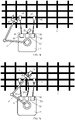
- the climbing machine moves as follows: First, as shown in FIG. 7b , the mechanical arm 2 moves the gripping mechanism 6 to the suspension mechanism 42, so that the gripping mechanism 6 is connected to the suspension mechanism 42.
- the reel mechanism 52 increases the length of the rope 32 between the suspension mechanism 42 and the machine body 1 by releasing the rope, so that the rope 32 is in the loose state and has a proper length.
- the mechanical arm 2 places the suspension mechanism 42 in a proper position on the object structure P, so that the suspension mechanism 42 is connected to the object structure P.
- the gripping mechanism 6 disengages the suspension mechanism 42. This process is equivalent to step 1 described above.
- the three suspension mechanisms 4 are all connected to the object structure P. Then, as shown in FIG. 7c , the three reel mechanisms 5 wind the ropes to shorten the lengths of the ropes between the three suspension mechanisms 4 and the machine body 1, so that the ropes pull the machine body 1 to move on the object structure P. This process is equivalent to step 3 described above.
- step 2 described above is not mandatory.
- the mechanical arm 2 moves the gripping mechanism 6 to the suspension mechanism 41, so that the gripping mechanism 6 is connected to the suspension mechanism 41.
- the length of the rope 31 between the suspension mechanism 41 and the machine body 1 is increased, so that the rope 31 is in the loose state and has a proper length.
- the mechanical arm 2 places the suspension mechanism 41 in a proper position on the object structure P, so that the suspension mechanism 41 is connected to the object structure P.
- the gripping mechanism 6 disengages the suspension mechanism 41. This process is equivalent to step 1 described above.
- the mechanical arm 2 moves the gripping mechanism 6 to the suspension mechanism 43, so that the gripping mechanism 6 is connected to the suspension mechanism 43.
- the length of the rope 33 between the suspension mechanism 43 and the machine body 1 is increased, so that the rope 33 is in the loose state and has a proper length.
- the mechanical arm 2 places the suspension mechanism 43 in a proper position on the object structure P, so that the suspension mechanism 43 is connected to the object structure P.
- the gripping mechanism 6 disengages the suspension mechanism 43. This process is equivalent to step 2 described above, that is, the process of step 1 is repeated to place other suspension mechanisms.
- the machine body can move on the object structure P.
- the climbing machine in the present invention has the following advantages when compared with an existing multi-arm moving machine.
- the quantity of mechanical arms 2' disposed on a machine body 1' of the existing multi-arm moving machine is the same as the quantity of suspension mechanisms 4', causing a heavy overall weight of the mechanism.
- the mechanical arm 2' has more degrees of freedom, there are more joints and more joint driving motors, and the overall weight increases sharply.
- only one mechanical arm 2 is required to move multiple suspension mechanisms 4.
- the present invention greatly reduces the overall weight of the moving mechanism by reducing the quantity of mechanical arms 2 and by using ultralight ropes 3.
- each mechanical arm 2' of the existing multi-arm moving mechanism cannot be disengaged from the suspension mechanism 4', resulting in a unitary function of the mechanical arm 2'.
- the mechanical arm 2 can be disengaged from the suspension mechanism 4. Therefore, the mechanical arm 2 can further play another role.
- the mechanical arm 2 can grip a camera after being disengaged from the suspension mechanism 4, to perform photographing.
- the mechanical arm 2 can grip a detection apparatus after being disengaged from the suspension mechanism 4 to implement a detection operation.
- a polygon ABCDEFGH is formed by combining a suspension point of a first suspension mechanism, joints of a first mechanical arm, a suspension point of a second suspension mechanism, and joints of a second mechanical arm. As all the joints of the mechanical arms 2' are motor-driven and interfere with each other during moving, all the joints need to strictly coordinate with each other, which is highly difficult to control.
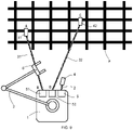
- FIG. 9 is used as an example for description.
- a suspension point of the first suspension mechanism 41, the first reel mechanism 51, a suspension point of the second suspension mechanism 42, and the second reel mechanism 52 form a trapezoid ABCD.
- the two flexible ropes 3 deform the trapezoid structure arbitrarily, and the two reel mechanisms 5 do not need strict coordination control.
Landscapes
- Engineering & Computer Science (AREA)
- Mechanical Engineering (AREA)
- Chemical & Material Sciences (AREA)
- Combustion & Propulsion (AREA)
- Transportation (AREA)
- Robotics (AREA)
- Manipulator (AREA)
- Movable Scaffolding (AREA)
Claims (11)
- Klettermaschine, umfassend einen Maschinenkörper (1), einen mechanischen Arm (2) und mindestens zwei Seile (3), wobei ein Ende jedes Seils mit einem Aufhängungsmechanismus (4) verbunden ist und das andere Ende des Seils mit dem Maschinenkörper (1) verbunden ist;wobei der Aufhängungsmechanismus mit einer Objektstruktur (P) verbunden oder aus einem Eingriff damit gelöst ist, unddie Länge des Seils zwischen dem Aufhängungsmechanismus und dem Maschinenkörper verstellbar ist; wobei durch Zerren oder Ziehen des Seils der Aufhängungsmechanismus ermöglicht, den Maschinenkörper auf der Objektstruktur zu bewegen; wobei der mechanische Arm einen oder mehr Freiheitsgrade aufweist; wobei ein Greifmechanismus (6) an einem Vorderende des mechanischen Arms angeordnet ist und ein Hinterende des mechanischen Arms auf dem Maschinenkörper montiert ist; wobei der Greifmechanismus eine Fähigkeit zur räumlichen Bewegung und/oder eine Fähigkeit zur Winkeleinstellung aufweist, wenn er durch den mechanischen Arm angetrieben wird, und in der Lage ist, einen Aufhängungsmechanismus zu greifen und zu bewegen sowie aus einem Eingriff mit einem gegriffenen Aufhängungsmechanismus gelöst zu werden, wobei ein oder mehrere Dämpfungsmechanismen (8) auf dem Maschinenkörper angeordnet sind und der Dämpfungsmechanismus in der Lage ist, eine Dämpfungskraft unter Verwendung eines Luftstroms zu erzeugen,dadurch gekennzeichnet, dasseine Schüttelzustand-Erfassungsvorrichtung auf dem Maschinenkörper angeordnet ist und die Schüttelzustand-Erfassungsvorrichtung in der Lage ist, einen Schüttelzustand des Maschinenkörpers zu erfassen.
- Klettermaschine nach Anspruch 1, wobei der Maschinenkörper einen Rollenmechanismus (5) umfasst und der Rollenmechanismus das Seil zwischen dem Maschinenkörper und dem Aufhängungsmechanismus aufwickelt oder freigibt, um die Länge des Seils zu verändern, sodass der Maschinenkörper in der Lage ist, sich auf der Objektstruktur zu bewegen.
- Klettermaschine nach Anspruch 1, wobei der Aufhängungsmechanismus einen Rollenmechanismus umfasst und der Rollenmechanismus das Seil zwischen dem Aufhängungsmechanismus und dem Maschinenkörper aufwickelt oder freigibt, um die Länge des Seils zu verändern, sodass der Maschinenkörper in der Lage ist, sich auf der Objektstruktur zu bewegen.
- Klettermaschine nach Anspruch 1, 2 oder 3, wobei der Greifmechanismus eine magnetische Saugvorrichtung umfasst, wobei eine magnetisch angesaugte magnetisch leitfähige Fläche auf dem Aufhängungsmechanismus angeordnet ist und die magnetische Saugvorrichtung in der Lage ist, den Aufhängungsmechanismus anzusaugen oder aus einem Eingriff damit gelöst zu werden.
- Klettermaschine nach Anspruch 1, 2 oder 3, wobei der Greifmechanismus eine mechanische Klaue umfasst und die mechanische Klaue öffnet oder schließt, um den Aufhängungsmechanismus zu greifen oder aus einem Eingriff damit gelöst zu werden.
- Klettermaschine nach Anspruch 1, 2 oder 3, wobei der Aufhängungsmechanismus einen Haken umfasst und der Haken sich in die Objektstruktur einhakt oder aus einem Eingriff damit gelöst wird, um eine Verbindung oder ein Lösen eines Eingriffs zwischen dem Aufhängungsmechanismus und der Objektstruktur umzusetzen.
- Klettermaschine nach Anspruch 1, 2 oder 3, wobei der Aufhängungsmechanismus einen Sauger umfasst und der Sauger verwendet wird, um die Objektstruktur anzusaugen oder sich aus einem Eingriff damit zu lösen, um eine Ansaugung oder ein Lösen eines Eingriffs zwischen dem Aufhängungsmechanismus und der Objektstruktur umzusetzen.
- Klettermaschine nach Anspruch 1, wobei der Dämpfungsmechanismus eine Rotorvorrichtung umfasst und die Rotorvorrichtung eine Kraft, die durch einen Rotor durch Drehung in der Luft erzeugt wird, verwendet, um ein Schütteln des Maschinenkörpers in einem aufgehängten Zustand zu reduzieren.
- Klettermaschine nach Anspruch 1, wobei der Dämpfungsmechanismus eine Lufteinspritzvorrichtung umfasst und die Lufteinspritzvorrichtung einen Reaktionsschub einer Lufteinspritzung verwendet, um ein Schütteln des Maschinenkörpers in einem aufgehängten Zustand zu reduzieren.
- Klettermaschine nach Anspruch 1, 2 oder 3, wobei mehrere Räder (9) auf dem Maschinenkörper angeordnet sind.
- Bewegungsverfahren für die Klettermaschine nach einem der Ansprüche 1 bis 10, umfassend die folgenden Schritte:Schritt 1: Bewegen, durch den mechanischen Arm (2), des Greifmechanismus (6) zu dem Aufhängungsmechanismus (4), sodass der Greifmechanismus mit dem Aufhängungsmechanismus verbunden wird; Erhöhen der Länge des Seils (3) zwischen dem Aufhängungsmechanismus und dem Maschinenkörper (1), sodass sich das Seil in einem losen Zustand befindet; Platzieren, durch den mechanischen Arm, des Aufhängungsmechanismus in einer angemessenen Position auf der Objektstruktur, sodass der Aufhängungsmechanismus mit der Objektstruktur verbunden wird; und Lösen eines Eingriffs, durch den Greifmechanismus, des Aufhängungsmechanismus;Schritt 2: Wiederholen von Schritt 1 basierend auf einer tatsächlichen Anforderung, sodass andere Aufhängungsmechanismen in angemessenen Positionen auf der Objektstruktur (P) platziert und mit der Objektstruktur verbunden werden;Schritt 3: Verkürzen der Länge eines Seils zwischen jedem Aufhängungsmechanismus und dem Maschinenkörper (1), sodass das Seil den Maschinenkörper zieht, um ihn auf der Objektstruktur zu bewegen; undSchritt 4: Wiederholen von Schritt 1, Schritt 2 und Schritt 3, sodass der Maschinenkörper in der Lage ist, sich auf der Objektstruktur zu bewegen.
Applications Claiming Priority (1)
| Application Number | Priority Date | Filing Date | Title |
|---|---|---|---|
| CN202010098322.XA CN111216819B (zh) | 2020-02-18 | 2020-02-18 | 攀爬机器及其移动方法 |
Publications (2)
| Publication Number | Publication Date |
|---|---|
| EP3868517A1 EP3868517A1 (de) | 2021-08-25 |
| EP3868517B1 true EP3868517B1 (de) | 2022-05-11 |
Family
ID=70826126
Family Applications (1)
| Application Number | Title | Priority Date | Filing Date |
|---|---|---|---|
| EP20191275.5A Active EP3868517B1 (de) | 2020-02-18 | 2020-08-17 | Klettermaschine und bewegungsverfahren dafür |
Country Status (4)
| Country | Link |
|---|---|
| US (1) | US11878751B2 (de) |
| EP (1) | EP3868517B1 (de) |
| JP (1) | JP7266806B2 (de) |
| CN (1) | CN111216819B (de) |
Families Citing this family (7)
| Publication number | Priority date | Publication date | Assignee | Title |
|---|---|---|---|---|
| CN112110391B (zh) * | 2019-06-20 | 2024-11-22 | 杭州孚亚科技有限公司 | 一种作业系统 |
| CN112093741B (zh) * | 2020-09-23 | 2025-09-16 | 浙江大学 | 倾斜面移动机器和多机器人系统及其使用方法 |
| CN113895536B (zh) * | 2021-11-18 | 2022-09-27 | 国网湖南省电力有限公司 | 一种仿生爬塔机器人 |
| CN115871810B (zh) * | 2022-01-02 | 2026-04-10 | 浙江大学 | 绳索移动机器及多机器移动系统 |
| CN115452867A (zh) * | 2022-07-05 | 2022-12-09 | 郑尚高 | 一种输电线路无人高空x射线无损探伤系统及无损探伤方法 |
| CN115369760B (zh) * | 2022-09-28 | 2025-10-10 | 深圳市人工智能与机器人研究院 | 一种桥梁主体的检修机器 |
| CN116374814A (zh) * | 2023-03-08 | 2023-07-04 | 中建安装集团有限公司 | 一种管廊上自动爬行与搬运装置 |
Family Cites Families (23)
| Publication number | Priority date | Publication date | Assignee | Title |
|---|---|---|---|---|
| JP2796469B2 (ja) * | 1992-03-13 | 1998-09-10 | 三菱重工業株式会社 | 空間移動装置 |
| JP2794106B2 (ja) * | 1994-10-05 | 1998-09-03 | ドーエイ外装有限会社 | 作業用ゴンドラ |
| WO2005089346A2 (en) * | 2004-03-15 | 2005-09-29 | The University Of Vermont And State Agricultural College | Systems comprising a mechanically actuated magnetic on-off attachment device |
| CN201033434Y (zh) * | 2006-10-25 | 2008-03-12 | 哈尔滨工程大学 | 仿壁虎微小型机器人 |
| JP5061356B2 (ja) * | 2007-04-12 | 2012-10-31 | 独立行政法人 宇宙航空研究開発機構 | 移動ロボット |
| CN101744590A (zh) * | 2010-01-14 | 2010-06-23 | 刘太浩 | 一种悬吊装置及其幕墙清洗机器人 |
| JP2011255490A (ja) * | 2010-05-13 | 2011-12-22 | National Institute Of Advanced Industrial Science & Technology | ロボット本体のキャスティング方法及び装置 |
| CN201977716U (zh) * | 2011-04-18 | 2011-09-21 | 崔小军 | 高层建筑玻璃清洗机 |
| JP5849901B2 (ja) * | 2012-08-30 | 2016-02-03 | 新日鐵住金株式会社 | 移動車両 |
| US10112664B2 (en) * | 2014-01-29 | 2018-10-30 | Zhejiang University | Climbing robot vehicle |
| CN105971829B (zh) * | 2016-07-06 | 2018-10-12 | 福建省新能海上风电研发中心有限公司 | 一种载人爬壁高处作业装备及其使用方法 |
| CN106672103B (zh) * | 2016-11-29 | 2023-01-24 | 湖北第二师范学院 | 一种用于高楼外墙清洗及维护的物联网蜘蛛机器人 |
| CN108340364B (zh) * | 2017-01-24 | 2020-09-15 | 南京原觉信息科技有限公司 | 爬行机器装置与其部署方法 |
| CN206702730U (zh) * | 2017-03-28 | 2017-12-05 | 马鞍山华东回转支承有限公司 | 一种回转支承切削加工用机械手 |
| US10829170B2 (en) * | 2017-04-19 | 2020-11-10 | Zhejiang University | Multifunctional robot system and method |
| CN109222778A (zh) * | 2017-07-11 | 2019-01-18 | 王欢 | 一种带有姿态调整电动关节的攀壁机 |
| CN108265995B (zh) * | 2017-12-31 | 2020-08-14 | 北京品创智能科技有限公司 | 一种基于绳索并联技术的幕墙清洗设备 |
| CN208034688U (zh) * | 2018-01-17 | 2018-11-02 | 深圳市智能机器人研究院 | 一种四绳驱动机器人 |
| CN108466250B (zh) * | 2018-02-11 | 2020-08-07 | 坎德拉(深圳)科技创新有限公司 | 双轮配送机器人 |
| CN108643599B (zh) * | 2018-05-25 | 2020-11-06 | 杭州电子科技大学 | 拓扑三维悬挂结构幕墙清洁机器人系统及运动控制方法 |
| CN211844679U (zh) * | 2020-02-18 | 2020-11-03 | 浙江大学 | 攀爬机器 |
| US11191411B2 (en) * | 2020-04-29 | 2021-12-07 | France Vezina | Vertical surface cleaning autonomous device |
| CN112093741B (zh) * | 2020-09-23 | 2025-09-16 | 浙江大学 | 倾斜面移动机器和多机器人系统及其使用方法 |
-
2020
- 2020-02-18 CN CN202010098322.XA patent/CN111216819B/zh active Active
- 2020-08-17 EP EP20191275.5A patent/EP3868517B1/de active Active
-
2021
- 2021-01-22 US US17/156,433 patent/US11878751B2/en active Active
- 2021-01-25 JP JP2021009804A patent/JP7266806B2/ja active Active
Also Published As
| Publication number | Publication date |
|---|---|
| CN111216819A (zh) | 2020-06-02 |
| CN111216819B (zh) | 2023-12-22 |
| US20210253187A1 (en) | 2021-08-19 |
| JP7266806B2 (ja) | 2023-05-01 |
| US11878751B2 (en) | 2024-01-23 |
| EP3868517A1 (de) | 2021-08-25 |
| JP2021130190A (ja) | 2021-09-09 |
Similar Documents
| Publication | Publication Date | Title |
|---|---|---|
| US11878751B2 (en) | Climbing machine and moving method therefor | |
| CN211844679U (zh) | 攀爬机器 | |
| CN113601485B (zh) | 一种高层建筑外墙智能喷涂机器人 | |
| CN107200077B (zh) | 一种三体式爬壁机器人及其越障方法 | |
| CN108643599B (zh) | 拓扑三维悬挂结构幕墙清洁机器人系统及运动控制方法 | |
| CN105666519A (zh) | 一种机械手及一种蛇形机器臂系统装置的实现方法 | |
| CN204750525U (zh) | 一种可两级收放的潜器回收布放装置 | |
| CN211193912U (zh) | 一种配网架空线路带电作业机器人和握杆机械手 | |
| CN109795879B (zh) | 一种基于六自由度并联机构的调姿对接装置、系统及方法 | |
| CN113021388A (zh) | 一种气磁切换的多功能柔性卡爪机械臂 | |
| CN116730183B (zh) | 一种盘爪协助式智能减摇吊钩装置 | |
| CN118636118A (zh) | 一种高空作业的桁架机器人 | |
| CN108557041A (zh) | 一种双模态六自由度水下机器人及其操控方法 | |
| CN218698948U (zh) | 抓取装置 | |
| CN115369760B (zh) | 一种桥梁主体的检修机器 | |
| CN110340895A (zh) | 一种底盘抬升轮式机器人的控制系统及控制方法 | |
| WO2019068298A2 (en) | SYSTEM PROVIDED WITH A ROBOT ON A WIRE, ITS OPERATING METHOD, OPERATING SITE WITH SUCH A SYSTEM, AND ITS USE | |
| JPS60219170A (ja) | 能動体 | |
| CN117656042A (zh) | 一种绳索驱动的四自由度并联机器人末端执行器 | |
| CN210939269U (zh) | 一种全自动齿轮机器人 | |
| CN116945153A (zh) | 机械臂的控制方法、装置、设备及存储介质 | |
| CN120024157B (zh) | 基于仿生章鱼的多地形探测和抓取一体化机器人及控制方法 | |
| CN116946404A (zh) | 一种磁吸附式旋翼无人车检测系统 | |
| CN209453604U (zh) | 高楼外立面多功能遥控作业机器人 | |
| CN114436176A (zh) | 一种支撑面移动装置 |
Legal Events
| Date | Code | Title | Description |
|---|---|---|---|
| PUAI | Public reference made under article 153(3) epc to a published international application that has entered the european phase |
Free format text: ORIGINAL CODE: 0009012 |
|
| STAA | Information on the status of an ep patent application or granted ep patent |
Free format text: STATUS: REQUEST FOR EXAMINATION WAS MADE |
|
| 17P | Request for examination filed |
Effective date: 20210719 |
|
| AK | Designated contracting states |
Kind code of ref document: A1 Designated state(s): AL AT BE BG CH CY CZ DE DK EE ES FI FR GB GR HR HU IE IS IT LI LT LU LV MC MK MT NL NO PL PT RO RS SE SI SK SM TR |
|
| GRAP | Despatch of communication of intention to grant a patent |
Free format text: ORIGINAL CODE: EPIDOSNIGR1 |
|
| STAA | Information on the status of an ep patent application or granted ep patent |
Free format text: STATUS: GRANT OF PATENT IS INTENDED |
|
| INTG | Intention to grant announced |
Effective date: 20220103 |
|
| GRAS | Grant fee paid |
Free format text: ORIGINAL CODE: EPIDOSNIGR3 |
|
| GRAA | (expected) grant |
Free format text: ORIGINAL CODE: 0009210 |
|
| STAA | Information on the status of an ep patent application or granted ep patent |
Free format text: STATUS: THE PATENT HAS BEEN GRANTED |
|
| AK | Designated contracting states |
Kind code of ref document: B1 Designated state(s): AL AT BE BG CH CY CZ DE DK EE ES FI FR GB GR HR HU IE IS IT LI LT LU LV MC MK MT NL NO PL PT RO RS SE SI SK SM TR |
|
| REG | Reference to a national code |
Ref country code: GB Ref legal event code: FG4D |
|
| REG | Reference to a national code |
Ref country code: CH Ref legal event code: EP |
|
| REG | Reference to a national code |
Ref country code: AT Ref legal event code: REF Ref document number: 1490995 Country of ref document: AT Kind code of ref document: T Effective date: 20220515 |
|
| REG | Reference to a national code |
Ref country code: DE Ref legal event code: R096 Ref document number: 602020003153 Country of ref document: DE |
|
| REG | Reference to a national code |
Ref country code: IE Ref legal event code: FG4D |
|
| REG | Reference to a national code |
Ref country code: LT Ref legal event code: MG9D |
|
| REG | Reference to a national code |
Ref country code: NL Ref legal event code: MP Effective date: 20220511 |
|
| REG | Reference to a national code |
Ref country code: AT Ref legal event code: MK05 Ref document number: 1490995 Country of ref document: AT Kind code of ref document: T Effective date: 20220511 |
|
| PG25 | Lapsed in a contracting state [announced via postgrant information from national office to epo] |
Ref country code: SE Free format text: LAPSE BECAUSE OF FAILURE TO SUBMIT A TRANSLATION OF THE DESCRIPTION OR TO PAY THE FEE WITHIN THE PRESCRIBED TIME-LIMIT Effective date: 20220511 Ref country code: PT Free format text: LAPSE BECAUSE OF FAILURE TO SUBMIT A TRANSLATION OF THE DESCRIPTION OR TO PAY THE FEE WITHIN THE PRESCRIBED TIME-LIMIT Effective date: 20220912 Ref country code: NO Free format text: LAPSE BECAUSE OF FAILURE TO SUBMIT A TRANSLATION OF THE DESCRIPTION OR TO PAY THE FEE WITHIN THE PRESCRIBED TIME-LIMIT Effective date: 20220811 Ref country code: NL Free format text: LAPSE BECAUSE OF FAILURE TO SUBMIT A TRANSLATION OF THE DESCRIPTION OR TO PAY THE FEE WITHIN THE PRESCRIBED TIME-LIMIT Effective date: 20220511 Ref country code: LT Free format text: LAPSE BECAUSE OF FAILURE TO SUBMIT A TRANSLATION OF THE DESCRIPTION OR TO PAY THE FEE WITHIN THE PRESCRIBED TIME-LIMIT Effective date: 20220511 Ref country code: HR Free format text: LAPSE BECAUSE OF FAILURE TO SUBMIT A TRANSLATION OF THE DESCRIPTION OR TO PAY THE FEE WITHIN THE PRESCRIBED TIME-LIMIT Effective date: 20220511 Ref country code: GR Free format text: LAPSE BECAUSE OF FAILURE TO SUBMIT A TRANSLATION OF THE DESCRIPTION OR TO PAY THE FEE WITHIN THE PRESCRIBED TIME-LIMIT Effective date: 20220812 Ref country code: FI Free format text: LAPSE BECAUSE OF FAILURE TO SUBMIT A TRANSLATION OF THE DESCRIPTION OR TO PAY THE FEE WITHIN THE PRESCRIBED TIME-LIMIT Effective date: 20220511 Ref country code: BG Free format text: LAPSE BECAUSE OF FAILURE TO SUBMIT A TRANSLATION OF THE DESCRIPTION OR TO PAY THE FEE WITHIN THE PRESCRIBED TIME-LIMIT Effective date: 20220811 Ref country code: AT Free format text: LAPSE BECAUSE OF FAILURE TO SUBMIT A TRANSLATION OF THE DESCRIPTION OR TO PAY THE FEE WITHIN THE PRESCRIBED TIME-LIMIT Effective date: 20220511 |
|
| PGFP | Annual fee paid to national office [announced via postgrant information from national office to epo] |
Ref country code: DE Payment date: 20220729 Year of fee payment: 3 |
|
| PG25 | Lapsed in a contracting state [announced via postgrant information from national office to epo] |
Ref country code: RS Free format text: LAPSE BECAUSE OF FAILURE TO SUBMIT A TRANSLATION OF THE DESCRIPTION OR TO PAY THE FEE WITHIN THE PRESCRIBED TIME-LIMIT Effective date: 20220511 Ref country code: PL Free format text: LAPSE BECAUSE OF FAILURE TO SUBMIT A TRANSLATION OF THE DESCRIPTION OR TO PAY THE FEE WITHIN THE PRESCRIBED TIME-LIMIT Effective date: 20220511 Ref country code: LV Free format text: LAPSE BECAUSE OF FAILURE TO SUBMIT A TRANSLATION OF THE DESCRIPTION OR TO PAY THE FEE WITHIN THE PRESCRIBED TIME-LIMIT Effective date: 20220511 Ref country code: IS Free format text: LAPSE BECAUSE OF FAILURE TO SUBMIT A TRANSLATION OF THE DESCRIPTION OR TO PAY THE FEE WITHIN THE PRESCRIBED TIME-LIMIT Effective date: 20220911 |
|
| PGFP | Annual fee paid to national office [announced via postgrant information from national office to epo] |
Ref country code: FR Payment date: 20220822 Year of fee payment: 3 |
|
| PG25 | Lapsed in a contracting state [announced via postgrant information from national office to epo] |
Ref country code: SM Free format text: LAPSE BECAUSE OF FAILURE TO SUBMIT A TRANSLATION OF THE DESCRIPTION OR TO PAY THE FEE WITHIN THE PRESCRIBED TIME-LIMIT Effective date: 20220511 Ref country code: SK Free format text: LAPSE BECAUSE OF FAILURE TO SUBMIT A TRANSLATION OF THE DESCRIPTION OR TO PAY THE FEE WITHIN THE PRESCRIBED TIME-LIMIT Effective date: 20220511 Ref country code: RO Free format text: LAPSE BECAUSE OF FAILURE TO SUBMIT A TRANSLATION OF THE DESCRIPTION OR TO PAY THE FEE WITHIN THE PRESCRIBED TIME-LIMIT Effective date: 20220511 Ref country code: ES Free format text: LAPSE BECAUSE OF FAILURE TO SUBMIT A TRANSLATION OF THE DESCRIPTION OR TO PAY THE FEE WITHIN THE PRESCRIBED TIME-LIMIT Effective date: 20220511 Ref country code: EE Free format text: LAPSE BECAUSE OF FAILURE TO SUBMIT A TRANSLATION OF THE DESCRIPTION OR TO PAY THE FEE WITHIN THE PRESCRIBED TIME-LIMIT Effective date: 20220511 Ref country code: DK Free format text: LAPSE BECAUSE OF FAILURE TO SUBMIT A TRANSLATION OF THE DESCRIPTION OR TO PAY THE FEE WITHIN THE PRESCRIBED TIME-LIMIT Effective date: 20220511 Ref country code: CZ Free format text: LAPSE BECAUSE OF FAILURE TO SUBMIT A TRANSLATION OF THE DESCRIPTION OR TO PAY THE FEE WITHIN THE PRESCRIBED TIME-LIMIT Effective date: 20220511 |
|
| REG | Reference to a national code |
Ref country code: DE Ref legal event code: R097 Ref document number: 602020003153 Country of ref document: DE |
|
| PLBE | No opposition filed within time limit |
Free format text: ORIGINAL CODE: 0009261 |
|
| STAA | Information on the status of an ep patent application or granted ep patent |
Free format text: STATUS: NO OPPOSITION FILED WITHIN TIME LIMIT |
|
| PG25 | Lapsed in a contracting state [announced via postgrant information from national office to epo] |
Ref country code: MC Free format text: LAPSE BECAUSE OF FAILURE TO SUBMIT A TRANSLATION OF THE DESCRIPTION OR TO PAY THE FEE WITHIN THE PRESCRIBED TIME-LIMIT Effective date: 20220511 Ref country code: AL Free format text: LAPSE BECAUSE OF FAILURE TO SUBMIT A TRANSLATION OF THE DESCRIPTION OR TO PAY THE FEE WITHIN THE PRESCRIBED TIME-LIMIT Effective date: 20220511 |
|
| 26N | No opposition filed |
Effective date: 20230214 |
|
| PG25 | Lapsed in a contracting state [announced via postgrant information from national office to epo] |
Ref country code: LU Free format text: LAPSE BECAUSE OF NON-PAYMENT OF DUE FEES Effective date: 20220817 |
|
| REG | Reference to a national code |
Ref country code: BE Ref legal event code: MM Effective date: 20220831 |
|
| PG25 | Lapsed in a contracting state [announced via postgrant information from national office to epo] |
Ref country code: IE Free format text: LAPSE BECAUSE OF NON-PAYMENT OF DUE FEES Effective date: 20220817 |
|
| PG25 | Lapsed in a contracting state [announced via postgrant information from national office to epo] |
Ref country code: BE Free format text: LAPSE BECAUSE OF NON-PAYMENT OF DUE FEES Effective date: 20220831 |
|
| PG25 | Lapsed in a contracting state [announced via postgrant information from national office to epo] |
Ref country code: IT Free format text: LAPSE BECAUSE OF FAILURE TO SUBMIT A TRANSLATION OF THE DESCRIPTION OR TO PAY THE FEE WITHIN THE PRESCRIBED TIME-LIMIT Effective date: 20220511 |
|
| REG | Reference to a national code |
Ref country code: DE Ref legal event code: R119 Ref document number: 602020003153 Country of ref document: DE |
|
| REG | Reference to a national code |
Ref country code: CH Ref legal event code: PL |
|
| PG25 | Lapsed in a contracting state [announced via postgrant information from national office to epo] |
Ref country code: CY Free format text: LAPSE BECAUSE OF FAILURE TO SUBMIT A TRANSLATION OF THE DESCRIPTION OR TO PAY THE FEE WITHIN THE PRESCRIBED TIME-LIMIT Effective date: 20220511 Ref country code: CH Free format text: LAPSE BECAUSE OF NON-PAYMENT OF DUE FEES Effective date: 20230831 |
|
| PG25 | Lapsed in a contracting state [announced via postgrant information from national office to epo] |
Ref country code: MK Free format text: LAPSE BECAUSE OF FAILURE TO SUBMIT A TRANSLATION OF THE DESCRIPTION OR TO PAY THE FEE WITHIN THE PRESCRIBED TIME-LIMIT Effective date: 20220511 Ref country code: HU Free format text: LAPSE BECAUSE OF FAILURE TO SUBMIT A TRANSLATION OF THE DESCRIPTION OR TO PAY THE FEE WITHIN THE PRESCRIBED TIME-LIMIT; INVALID AB INITIO Effective date: 20200817 |
|
| PG25 | Lapsed in a contracting state [announced via postgrant information from national office to epo] |
Ref country code: FR Free format text: LAPSE BECAUSE OF NON-PAYMENT OF DUE FEES Effective date: 20230831 Ref country code: DE Free format text: LAPSE BECAUSE OF NON-PAYMENT OF DUE FEES Effective date: 20240301 |
|
| PG25 | Lapsed in a contracting state [announced via postgrant information from national office to epo] |
Ref country code: MT Free format text: LAPSE BECAUSE OF FAILURE TO SUBMIT A TRANSLATION OF THE DESCRIPTION OR TO PAY THE FEE WITHIN THE PRESCRIBED TIME-LIMIT Effective date: 20220511 |
|
| PG25 | Lapsed in a contracting state [announced via postgrant information from national office to epo] |
Ref country code: BG Free format text: LAPSE BECAUSE OF FAILURE TO SUBMIT A TRANSLATION OF THE DESCRIPTION OR TO PAY THE FEE WITHIN THE PRESCRIBED TIME-LIMIT Effective date: 20220511 |
|
| PG25 | Lapsed in a contracting state [announced via postgrant information from national office to epo] |
Ref country code: BG Free format text: LAPSE BECAUSE OF FAILURE TO SUBMIT A TRANSLATION OF THE DESCRIPTION OR TO PAY THE FEE WITHIN THE PRESCRIBED TIME-LIMIT Effective date: 20220511 |
|
| GBPC | Gb: european patent ceased through non-payment of renewal fee |
Effective date: 20240817 |
|
| PG25 | Lapsed in a contracting state [announced via postgrant information from national office to epo] |
Ref country code: GB Free format text: LAPSE BECAUSE OF NON-PAYMENT OF DUE FEES Effective date: 20240817 |
|
| PG25 | Lapsed in a contracting state [announced via postgrant information from national office to epo] |
Ref country code: TR Free format text: LAPSE BECAUSE OF FAILURE TO SUBMIT A TRANSLATION OF THE DESCRIPTION OR TO PAY THE FEE WITHIN THE PRESCRIBED TIME-LIMIT Effective date: 20220511 |
|
| PG25 | Lapsed in a contracting state [announced via postgrant information from national office to epo] |
Ref country code: SI Free format text: LAPSE BECAUSE OF FAILURE TO SUBMIT A TRANSLATION OF THE DESCRIPTION OR TO PAY THE FEE WITHIN THE PRESCRIBED TIME-LIMIT Effective date: 20220511 |