EP3868517A1 - Climbing machine and moving method therefor - Google Patents
Climbing machine and moving method therefor Download PDFInfo
- Publication number
- EP3868517A1 EP3868517A1 EP20191275.5A EP20191275A EP3868517A1 EP 3868517 A1 EP3868517 A1 EP 3868517A1 EP 20191275 A EP20191275 A EP 20191275A EP 3868517 A1 EP3868517 A1 EP 3868517A1
- Authority
- EP
- European Patent Office
- Prior art keywords
- machine body
- suspension mechanism
- rope
- suspension
- object structure
- Prior art date
- Legal status (The legal status is an assumption and is not a legal conclusion. Google has not performed a legal analysis and makes no representation as to the accuracy of the status listed.)
- Granted
Links
Images





Classifications
-
- B—PERFORMING OPERATIONS; TRANSPORTING
- B62—LAND VEHICLES FOR TRAVELLING OTHERWISE THAN ON RAILS
- B62D—MOTOR VEHICLES; TRAILERS
- B62D57/00—Vehicles characterised by having other propulsion or other ground- engaging means than wheels or endless track, alone or in addition to wheels or endless track
- B62D57/02—Vehicles characterised by having other propulsion or other ground- engaging means than wheels or endless track, alone or in addition to wheels or endless track with ground-engaging propulsion means, e.g. walking members
- B62D57/024—Vehicles characterised by having other propulsion or other ground- engaging means than wheels or endless track, alone or in addition to wheels or endless track with ground-engaging propulsion means, e.g. walking members specially adapted for moving on inclined or vertical surfaces
-
- B—PERFORMING OPERATIONS; TRANSPORTING
- B25—HAND TOOLS; PORTABLE POWER-DRIVEN TOOLS; MANIPULATORS
- B25J—MANIPULATORS; CHAMBERS PROVIDED WITH MANIPULATION DEVICES
- B25J11/00—Manipulators not otherwise provided for
-
- B—PERFORMING OPERATIONS; TRANSPORTING
- B25—HAND TOOLS; PORTABLE POWER-DRIVEN TOOLS; MANIPULATORS
- B25J—MANIPULATORS; CHAMBERS PROVIDED WITH MANIPULATION DEVICES
- B25J5/00—Manipulators mounted on wheels or on carriages
Definitions
- the present invention pertains to the field of complex-structure moving technologies, and in particular, to a climbing machine and a moving method therefor.
- Climbing robots are important high-altitude special robots.
- a detection robot for a large road/bridge or a large oil tank or a large ship needs a mechanism that can climb and move on a wall surface, and a detection instrument is mounted on the climbing robot.
- the climbing robot is usually mounted with a suction mechanism.
- a suction force is generated between the suction mechanism and the wall surface, and the suction force causes a friction force between the robot and the wall surface.
- the friction force overcomes the gravity of the robot and further provides a driving force for the robot to move.
- the suction mechanism usually uses vacuum suction or magnetic suction.
- An object surface under suction needs to be a complete surface regardless of whether the robot uses vacuum suction or magnetic suction.
- the object surface under suction is a hollow surface, for example, a wire mesh, a steel frame, or a wooden fence, clearly, serious vacuum leakage occurs in vacuum suction, and there is no sufficient suction area for a magnetic suction mechanism to generate an enough magnetic force.
- a climbed object is not a plane but a structure with a complex shape, for example, a bending surface with a surface M and a surface N
- an existing vertical facade mobile robot (a wheel-driven structure) cannot move from the surface M to the surface N, because the suction force of the suction mechanism becomes invalid in a process of moving from the surface M to the surface N.
- the suction mechanism cannot adhere to the object surface, which causes a suction failure.
- a multi-joint multi-legged robot can cross a bending surface.
- it is very difficult to design such a robot as the multi-joint multi-legged design makes a robot mechanism very complex.
- many joint motors are needed, which greatly increases the robot weight.
- An increase of the robot weight is very detrimental to climbing a vertical facade, imposes a high requirement on the suction force of the suction mechanism, and raises a falling risk.
- the present invention provides a climbing machine and a moving method therefor.
- the climbing machine can not only move on a smooth surface, but also move on a complex structure (such as an iron tower, a wire mesh, or a steel frame) with a hollow surface.
- the climbing machine has a simple structure and a wide application scope, moves without interference, and features high safety.
- a climbing machine including a machine body, a mechanical arm, and at least two ropes, where one end of each rope is connected to a suspension mechanism, and the other end of the rope is connected to the machine body; the suspension mechanism is connected to or disengaged from an object structure, and the length of the rope between the suspension mechanism and the machine body is variable; through dragging or pulling of the rope, the suspension mechanism enables the machine body to move on the object structure; the mechanical arm has one or more degrees of freedom; a gripping mechanism is disposed at a front end of the mechanical arm, and a rear end of the mechanical arm is mounted on the machine body; the gripping mechanism has a spatial movement capability and/or an angle adjustment capability when driven by the mechanical arm, and is capable of gripping and moving any suspension mechanism and being disengaged from a gripped suspension mechanism.
- the machine body includes a reel mechanism, and the reel mechanism winds or releases the rope between the machine body and the suspension mechanism to change the length of the rope, so that the machine body is capable of moving on the object structure.
- the suspension mechanism includes a reel mechanism, and the reel mechanism winds or releases the rope between the suspension mechanism and the machine body to change the length of the rope, so that the machine body is capable of moving on the object structure.
- the gripping mechanism includes a magnetic suction device, a magnetically sucked magnetic conductive surface is disposed on the suspension mechanism, and the magnetic suction device is capable of sucking or being disengaged from the suspension mechanism.
- the gripping mechanism includes a mechanical claw, and the mechanical claw opens or closes to disengage or grip the suspension mechanism.
- suspension mechanism includes a hook, and the hook hooks or disengages the object structure, to implement connection or disengagement between the suspension mechanism and the object structure.
- suspension mechanism includes a sucker, and the sucker is used to suck or disengage the object structure, to implement suction or disengagement between the suspension mechanism and the object structure.
- one or more damping mechanisms are disposed on the machine body, and the damping mechanism is capable of generating a damping force by using an air flow.
- the damping mechanism includes a rotor apparatus, and the rotor apparatus uses a force generated by a rotor through rotation in the air to reduce shaking of the machine body in a suspended state.
- the damping mechanism includes an air injection apparatus, and the air injection apparatus uses a reaction thrust of air injection to reduce shaking of the machine body in a suspended state.
- a shaking state detection apparatus is disposed on the machine body, and the shaking state detection apparatus is capable of detecting a shaking state of the machine body.
- a moving method for the climbing machine described above is provided, including the following steps:
- the climbing machine includes the machine body, the mechanical arm, and the at least two ropes, where one end of each rope is connected to the suspension mechanism, and the other end of the rope is connected to the machine body; the suspension mechanism is connected to or disengaged from the object structure, and the length of the rope between the suspension mechanism and the machine body is variable; the suspension mechanism pulls or drags the machine body by using the rope to enable the machine body to move on the object structure; the gripping mechanism is disposed at the front end of the mechanical arm; the gripping mechanism has the spatial movement capability and/or the angle adjustment capability when driven by the mechanical arm, and is capable of gripping and moving any suspension mechanism and being disengaged from a gripped suspension mechanism.
- the machine body can be pulled not only on a smooth surface, but also on a hollow surface (for example, a wire mesh or a wooden fence) and a complex structure (for example, a steel frame, an iron tower, or a tree branch).
- a hollow surface for example, a wire mesh or a wooden fence
- a complex structure for example, a steel frame, an iron tower, or a tree branch.
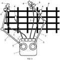
- FIG. 1 shows a preferred embodiment of a climbing machine according to the present invention.
- the climbing machine includes a machine body 1, a mechanical arm 2, and at least two ropes 3. One end of each rope is connected to a suspension mechanism 4, and the other end of the rope is connected to the machine body 1.
- the suspension mechanism 4 is connected to or disengaged from an object structure P.
- the length of the rope 3 between the suspension mechanism 4 and the machine body 1 is variable.
- the suspension mechanism 4 drags or pulls the machine body 1 by using the rope 3 to enable the machine body 1 to move on the object structure P.
- the machine body 1 includes a reel mechanism 5. One end of each rope 3 is connected to the suspension mechanism 4, and the other end is connected to the reel mechanism 5 on the machine body 1.
- the reel mechanism 5 winds and releases the rope 3 between the machine body 1 and the suspension mechanism 4 to change the length of the rope, so that the machine body 1 can move on the object structure P.
- the suspension mechanism 4 includes a reel mechanism 5. One end of each rope 3 is connected to the machine body 1, and the other end is connected to the reel mechanism 5 on the suspension mechanism 4. The reel mechanism 5 winds and releases the rope 3 between the suspension mechanism 4 and the machine body 1 to change the length of the rope, so that the machine body 1 can move on the object structure P.
- the suspension mechanism 4 can be connected to or disengaged from the object structure P.
- the suspension mechanism 4 drags or pulls the machine body 1 by using the rope 3 to enable the machine body 1 to move on the object structure P.
- the object structure P can be a smooth wall surface, a glass surface, or a hollow surface such as a wire mesh, a steel frame, an iron tower, a wooden fence, or a tree branch.
- the object structure P can be a planar structure (such as a wire mesh or a wall surface), or a three-dimensional structure (such as an iron tower). Therefore, the present invention is widely applicable.
- the mechanical arm 2 has one or more degrees of freedom.
- a gripping mechanism 6 is disposed at a front end of the mechanical arm 2.
- a rear end of the mechanical arm 2 is mounted on the machine body 1.
- the gripping mechanism 6 has a spatial movement capability and/or an angle adjustment capability when driven by the mechanical arm 2, and is capable of gripping and moving any suspension mechanism 4 and being disengaged from a gripped suspension mechanism 4.
- FIG. 1 shows a first embodiment of a climbing machine according to the present invention.
- the climbing machine is provided with one mechanical arm 2, three ropes 3, and suspension mechanisms 4 connected to the ropes.
- the three ropes 3 are referred to as a first rope 31, a second rope 32, and a third rope 33.
- three reel mechanisms 5 are referred to as a first reel mechanism 51, a second reel mechanism 52, and a third reel mechanism 53
- three suspension mechanisms 4 are referred to as a first suspension mechanism 41, a second suspension mechanism 42, and a third suspension mechanism 43.
- one mechanical arm 2 and one gripping mechanism 6 successively operate the three ropes 3 and the suspension mechanisms 4 connected to the three ropes 3.
- the gripping mechanism 6 can be a magnetic suction device.
- the suspension mechanism 4 is provided with a magnetically sucked magnetic conductive surface, and the magnetic suction device is capable of sucking or being disengaged from the suspension mechanism.
- the magnetic suction device is an electromagnetic iron. When the electromagnetic iron is powered on, generates a magnetic field, and approaches the suspension mechanism 4, the suspension mechanism 4 is sucked. When the electromagnetic iron is powered off, a magnetic force disappears, and the suspension mechanism 4 is disengaged.
- the gripping mechanism 6 is a mechanical claw, and the mechanical claw opens or closes to disengage or grip the suspension mechanism 4.
- the suspension mechanism 4 is a hook 44.
- An object structure P is a steel frame structure composed of many steel bars 7.
- the hook 44 is hooked to the steel bars 7, and the hook 44 and the steel bars 7 are connected to each other.
- the hook 44 can be disengaged from the steel bars 7, so that the hook 44 and the steel bars 7 are detached from each other, as shown in FIG. 2a .
- the suspension mechanism 4 can further be a sucker 45, and the sucker 45 is used to suck or disengage the object structure P, so as to implement suction or disengagement between the suspension mechanism 4 and the object structure P, as shown in FIG. 2b .
- the mechanical arm 2 is provided with a first lever arm 22 and a second lever arm 23.
- a lever arm revolute 21 is connected to one end of the first lever arm 22 and one end of the second lever arm 23.
- the other end of the first lever arm 22 is connected to a machine body 1 by using a body revolute 24.
- the lever arm revolute 21 and the body revolute 24 are separately controlled by using a motor.
- positions and angles of the suspension mechanisms 4 can be controlled by using the mechanical arm 2.
- the suspension mechanisms 4 can be controlled to be in any spatial position and at any angle by increasing the quantity of joints or increasing a degree of freedom of each joint.
- FIG. 1 and FIG. 3 jointly show a second embodiment of a climbing machine according to the present invention.
- This embodiment differs from the first embodiment mainly in that the climbing machine is provided with two mechanical arms 2, four ropes 3, and suspension mechanisms 4 connected to the ropes 3.
- the quantity of mechanical arms 2 is less than the quantity of ropes 3 and the quantity of suspension mechanisms 4 connected to the ropes 3.
- the two mechanical arms 2 can operate two suspension mechanisms 4 at the same time, thereby reducing the time for placing the suspension mechanisms 4 and improving overall movement efficiency of the mechanism.
- FIG. 1 and FIG. 4 jointly show a third embodiment of a climbing machine according to the present invention.
- This embodiment differs from the first embodiment mainly in that one or more damping mechanisms 8 are disposed on the machine body 1, and the damping mechanism 8 can generate a damping force by using an air flow.
- the damping mechanism 8 is one or more air injection apparatuses, which use a reaction thrust of air injection to generate the damping force, so as to reduce shaking of the machine body 1 in a suspended state.
- the damping mechanism 8 is one or more rotor apparatuses. The rotor apparatus uses a force generated by a rotor through rotation in the air to reduce shaking of the machine body 1 in the suspended state.
- a shaking state detection apparatus is disposed on the machine body 1 to detect a motion state (acceleration, a speed, and the like) of the machine body 1 in real time.
- a multi-axis acceleration sensor is disposed in the shaking state detection apparatus to detect a shaking frequency and acceleration of the machine body 1 in a spatial direction, and integrate the acceleration to obtain a speed and its time-varying changes.
- the rotor apparatus of the damping mechanism 8 and the shaking state detection apparatus form a control system. That is, the magnitude and the direction of a force of the rotor apparatus are controlled based on a shaking state of the machine body 1 fed back by the shaking state detection apparatus, thereby generating a damping effect of suppressing shaking of the machine body 1.
- FIG. 1 and FIG. 5 jointly show a fourth embodiment of a climbing machine according to the present invention.
- Several wheels 9 are mounted on the machine body 1. Advantages of disposing the wheels 9 include the following: (1) The wheels enable the whole mechanism to move efficiently on a horizontal ground. (2) As shown in FIG. 6 , the reel mechanism 5 shortens the length of the rope between the machine body 1 and the suspension mechanism 4 by winding the rope, so that the machine body 1 moves upward. When there is a large protrusion N on the object structure P, if there is no wheel 9, the machine body 1 is stuck to the protrusion N. Consequently, an upward movement is blocked, and the mechanism can even be damaged by pulling in a serious case. Disposing the wheels 9 can properly solve this problem. When the wheels 9 are driven to rotate, a friction force can be formed between the wheels 9 and the protrusion N (as shown by an arrow in the figure). The friction force can drive the machine body 1 to move across the projection N.
- the present invention further discloses a moving method for the climbing machine described above, including the following steps:
- the climbing machine is provided with one mechanical arm 2, three ropes 3, and suspension mechanisms 4 connected to the ropes 3.
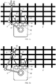
- FIG. 7a shows an initial state.
- the three ropes 3 are referred to as a first rope 31, a second rope 32, and a third rope 33.
- three reel mechanisms 5 are referred to as a first reel mechanism 51, a second reel mechanism 52, and a third reel mechanism 53
- three suspension mechanisms 4 are referred to as a first suspension mechanism 41, a second suspension mechanism 42, and a third suspension mechanism 43.
- the climbing machine moves as follows: First, as shown in FIG. 7b , the mechanical arm 2 moves the gripping mechanism 6 to the suspension mechanism 42, so that the gripping mechanism 6 is connected to the suspension mechanism 42.
- the reel mechanism 52 increases the length of the rope 32 between the suspension mechanism 42 and the machine body 1 by releasing the rope, so that the rope 32 is in the loose state and has a proper length.
- the mechanical arm 2 places the suspension mechanism 42 in a proper position on the object structure P, so that the suspension mechanism 42 is connected to the object structure P.
- the gripping mechanism 6 disengages the suspension mechanism 42. This process is equivalent to step 1 described above.
- the three suspension mechanisms 4 are all connected to the object structure P. Then, as shown in FIG. 7c , the three reel mechanisms 5 wind the ropes to shorten the lengths of the ropes between the three suspension mechanisms 4 and the machine body 1, so that the ropes pull the machine body 1 to move on the object structure P. This process is equivalent to step 3 described above.
- step 2 described above is not mandatory.
- the mechanical arm 2 moves the gripping mechanism 6 to the suspension mechanism 41, so that the gripping mechanism 6 is connected to the suspension mechanism 41.
- the length of the rope 31 between the suspension mechanism 41 and the machine body 1 is increased, so that the rope 31 is in the loose state and has a proper length.
- the mechanical arm 2 places the suspension mechanism 41 in a proper position on the object structure P, so that the suspension mechanism 41 is connected to the object structure P.
- the gripping mechanism 6 disengages the suspension mechanism 41. This process is equivalent to step 1 described above.
- the mechanical arm 2 moves the gripping mechanism 6 to the suspension mechanism 43, so that the gripping mechanism 6 is connected to the suspension mechanism 43.
- the length of the rope 33 between the suspension mechanism 43 and the machine body 1 is increased, so that the rope 33 is in the loose state and has a proper length.
- the mechanical arm 2 places the suspension mechanism 43 in a proper position on the object structure P, so that the suspension mechanism 43 is connected to the object structure P.
- the gripping mechanism 6 disengages the suspension mechanism 43. This process is equivalent to step 2 described above, that is, the process of step 1 is repeated to place other suspension mechanisms.
- the machine body can move on the object structure P.
- the climbing machine in the present invention has the following advantages when compared with an existing multi-arm moving machine.
- the quantity of mechanical arms 2' disposed on a machine body 1' of the existing multi-arm moving machine is the same as the quantity of suspension mechanisms 4', causing a heavy overall weight of the mechanism.
- the mechanical arm 2' has more degrees of freedom, there are more joints and more joint driving motors, and the overall weight increases sharply.
- only one mechanical arm 2 is required to move multiple suspension mechanisms 4.
- the present invention greatly reduces the overall weight of the moving mechanism by reducing the quantity of mechanical arms 2 and by using ultralight ropes 3.
- each mechanical arm 2' of the existing multi-arm moving mechanism cannot be disengaged from the suspension mechanism 4', resulting in a unitary function of the mechanical arm 2'.
- the mechanical arm 2 can be disengaged from the suspension mechanism 4. Therefore, the mechanical arm 2 can further play another role.
- the mechanical arm 2 can grip a camera after being disengaged from the suspension mechanism 4, to perform photographing.
- the mechanical arm 2 can grip a detection apparatus after being disengaged from the suspension mechanism 4 to implement a detection operation.
- a polygon ABCDEFGH is formed by combining a suspension point of a first suspension mechanism, joints of a first mechanical arm, a suspension point of a second suspension mechanism, and joints of a second mechanical arm.
- all the joints of the mechanical arms 2' are motor-driven and interfere with each other during moving, all the joints need to strictly coordinate with each other, which is highly difficult to control. If an action of one joint is faulty, the polygon ABCDEFGH is stuck, causing serious problems such as a burnt motor and a broken mechanism.
- the ropes 3 are flexible and do not cause problems such as a stuck mechanism and mechanism interference.
- FIG. 9 is used as an example for description.
- a suspension point of the first suspension mechanism 41, the first reel mechanism 51, a suspension point of the second suspension mechanism 42, and the second reel mechanism 52 form a trapezoid ABCD.
- the two flexible ropes 3 deform the trapezoid structure arbitrarily, and the two reel mechanisms 5 do not need strict coordination control.
Landscapes
- Engineering & Computer Science (AREA)
- Mechanical Engineering (AREA)
- Chemical & Material Sciences (AREA)
- Combustion & Propulsion (AREA)
- Transportation (AREA)
- Robotics (AREA)
- Manipulator (AREA)
- Movable Scaffolding (AREA)
Abstract
Description
- The present invention pertains to the field of complex-structure moving technologies, and in particular, to a climbing machine and a moving method therefor.
- Climbing robots are important high-altitude special robots. For example, a detection robot for a large road/bridge or a large oil tank or a large ship needs a mechanism that can climb and move on a wall surface, and a detection instrument is mounted on the climbing robot. The climbing robot is usually mounted with a suction mechanism. A suction force is generated between the suction mechanism and the wall surface, and the suction force causes a friction force between the robot and the wall surface. The friction force overcomes the gravity of the robot and further provides a driving force for the robot to move. The suction mechanism usually uses vacuum suction or magnetic suction. However, such a robot has the following problems:
An object surface under suction needs to be a complete surface regardless of whether the robot uses vacuum suction or magnetic suction. If the object surface under suction is a hollow surface, for example, a wire mesh, a steel frame, or a wooden fence, clearly, serious vacuum leakage occurs in vacuum suction, and there is no sufficient suction area for a magnetic suction mechanism to generate an enough magnetic force. - If a climbed object is not a plane but a structure with a complex shape, for example, a bending surface with a surface M and a surface N, an existing vertical facade mobile robot (a wheel-driven structure) cannot move from the surface M to the surface N, because the suction force of the suction mechanism becomes invalid in a process of moving from the surface M to the surface N. For example, when sucking a bending object surface, the suction mechanism cannot adhere to the object surface, which causes a suction failure.
- Theoretically, a multi-joint multi-legged robot can cross a bending surface. However, it is very difficult to design such a robot, as the multi-joint multi-legged design makes a robot mechanism very complex. In addition, many joint motors are needed, which greatly increases the robot weight. An increase of the robot weight is very detrimental to climbing a vertical facade, imposes a high requirement on the suction force of the suction mechanism, and raises a falling risk.
- To resolve a technical problem, the present invention provides a climbing machine and a moving method therefor. The climbing machine can not only move on a smooth surface, but also move on a complex structure (such as an iron tower, a wire mesh, or a steel frame) with a hollow surface. In addition, the climbing machine has a simple structure and a wide application scope, moves without interference, and features high safety.
- The present invention is implemented as follows: A climbing machine is provided, including a machine body, a mechanical arm, and at least two ropes, where one end of each rope is connected to a suspension mechanism, and the other end of the rope is connected to the machine body; the suspension mechanism is connected to or disengaged from an object structure, and the length of the rope between the suspension mechanism and the machine body is variable; through dragging or pulling of the rope, the suspension mechanism enables the machine body to move on the object structure; the mechanical arm has one or more degrees of freedom; a gripping mechanism is disposed at a front end of the mechanical arm, and a rear end of the mechanical arm is mounted on the machine body; the gripping mechanism has a spatial movement capability and/or an angle adjustment capability when driven by the mechanical arm, and is capable of gripping and moving any suspension mechanism and being disengaged from a gripped suspension mechanism.
- Further, the machine body includes a reel mechanism, and the reel mechanism winds or releases the rope between the machine body and the suspension mechanism to change the length of the rope, so that the machine body is capable of moving on the object structure.
- Further, the suspension mechanism includes a reel mechanism, and the reel mechanism winds or releases the rope between the suspension mechanism and the machine body to change the length of the rope, so that the machine body is capable of moving on the object structure.
- Further, the gripping mechanism includes a magnetic suction device, a magnetically sucked magnetic conductive surface is disposed on the suspension mechanism, and the magnetic suction device is capable of sucking or being disengaged from the suspension mechanism.
- Further, the gripping mechanism includes a mechanical claw, and the mechanical claw opens or closes to disengage or grip the suspension mechanism.
- Further, the suspension mechanism includes a hook, and the hook hooks or disengages the object structure, to implement connection or disengagement between the suspension mechanism and the object structure.
- Further, the suspension mechanism includes a sucker, and the sucker is used to suck or disengage the object structure, to implement suction or disengagement between the suspension mechanism and the object structure.
- Further, one or more damping mechanisms are disposed on the machine body, and the damping mechanism is capable of generating a damping force by using an air flow.
- Further, the damping mechanism includes a rotor apparatus, and the rotor apparatus uses a force generated by a rotor through rotation in the air to reduce shaking of the machine body in a suspended state.
- Further, the damping mechanism includes an air injection apparatus, and the air injection apparatus uses a reaction thrust of air injection to reduce shaking of the machine body in a suspended state.
- Further, a shaking state detection apparatus is disposed on the machine body, and the shaking state detection apparatus is capable of detecting a shaking state of the machine body.
- Further, several wheels are disposed on the machine body.
- The present invention is implemented as follows: A moving method for the climbing machine described above is provided, including the following steps:
- step 1: moving, by the mechanical arm, the gripping mechanism to one of the suspension mechanisms, so that the gripping mechanism is connected to the suspension mechanism; increasing the length of the rope between the suspension mechanism and the machine body, so that the rope is in a loose state; placing, by the mechanical arm, the suspension mechanism in a proper position on the object structure, so that the suspension mechanism is connected to the object structure; and disengaging, by the gripping mechanism, the suspension mechanism;
- step 2: repeating
step 1 based on an actual requirement, so that other suspension mechanisms are placed in proper positions on the object structure and are connected to the object structure; - step 3: shortening the length of a rope between each suspension mechanism and the machine body, so that the rope pulls the machine body to move on the object structure; and
- step 4: repeating
step 1,step 2, andstep 3, so that the machine body is capable of moving on the object structure. - Compared with the prior technology, according to the climbing machine and the moving method therefor in the present invention, the climbing machine includes the machine body, the mechanical arm, and the at least two ropes, where one end of each rope is connected to the suspension mechanism, and the other end of the rope is connected to the machine body; the suspension mechanism is connected to or disengaged from the object structure, and the length of the rope between the suspension mechanism and the machine body is variable; the suspension mechanism pulls or drags the machine body by using the rope to enable the machine body to move on the object structure; the gripping mechanism is disposed at the front end of the mechanical arm; the gripping mechanism has the spatial movement capability and/or the angle adjustment capability when driven by the mechanical arm, and is capable of gripping and moving any suspension mechanism and being disengaged from a gripped suspension mechanism. In the present invention, no interference occurs when the machine body is driven to move, and safety is high. Therefore, the machine body can be pulled not only on a smooth surface, but also on a hollow surface (for example, a wire mesh or a wooden fence) and a complex structure (for example, a steel frame, an iron tower, or a tree branch). The present invention features a simple structure, a wide application scope, and the like.
-
-
FIG. 1 is a schematic plan view of a structural principle of a first embodiment of a climbing machine according to the present invention; -
FIG. 2a is a schematic structural diagram of a state in which a hook and a bracket are combined in the first embodiment, andFIG. 2b is a schematic structural diagram of a state in which a vacuum sucker and a suction plane are under suction in the first embodiment; -
FIG. 3 is a schematic plan view of a structural principle of a second embodiment of a climbing machine according to the present invention; -
FIG. 4 is a schematic plan view of a structural principle of a third embodiment of a climbing machine according to the present invention; -
FIG. 5 is a schematic plan view of a structural principle of a fourth embodiment of a climbing machine according to the present invention; -
FIG. 6 is a schematic diagram of a state in which wheels of the climbing machine inFIG. 5 move across a protrusion; -
FIG. 7a to FIG. 7f are respectively schematic diagrams of steps of a rope pulling process of a climbing machine according to the present invention; -
FIG. 8 is a schematic diagram of a structural principle of a multi-arm moving mechanism in the prior technology; and -
FIG. 9 is a schematic diagram of comparison between a structure inFIG. 8 and a climbing machine according to the present invention. - To make the problems to be resolved, technical solutions, and beneficial effects of the present invention clearer and more comprehensible, the following further describes the present invention in detail with reference to the accompanying drawings and embodiments. It should be understood that the specific embodiments described herein are merely used to explain the present invention but are not intended to limit the present invention.
-
FIG. 1 shows a preferred embodiment of a climbing machine according to the present invention. The climbing machine includes amachine body 1, amechanical arm 2, and at least tworopes 3. One end of each rope is connected to asuspension mechanism 4, and the other end of the rope is connected to themachine body 1. Thesuspension mechanism 4 is connected to or disengaged from an object structure P. The length of therope 3 between thesuspension mechanism 4 and themachine body 1 is variable. Thesuspension mechanism 4 drags or pulls themachine body 1 by using therope 3 to enable themachine body 1 to move on the object structure P. - In another optional mounting form, the
machine body 1 includes areel mechanism 5. One end of eachrope 3 is connected to thesuspension mechanism 4, and the other end is connected to thereel mechanism 5 on themachine body 1. Thereel mechanism 5 winds and releases therope 3 between themachine body 1 and thesuspension mechanism 4 to change the length of the rope, so that themachine body 1 can move on the object structure P. - In another optional mounting form, the
suspension mechanism 4 includes areel mechanism 5. One end of eachrope 3 is connected to themachine body 1, and the other end is connected to thereel mechanism 5 on thesuspension mechanism 4. Thereel mechanism 5 winds and releases therope 3 between thesuspension mechanism 4 and themachine body 1 to change the length of the rope, so that themachine body 1 can move on the object structure P. - The
suspension mechanism 4 can be connected to or disengaged from the object structure P. Thesuspension mechanism 4 drags or pulls themachine body 1 by using therope 3 to enable themachine body 1 to move on the object structure P. The object structure P can be a smooth wall surface, a glass surface, or a hollow surface such as a wire mesh, a steel frame, an iron tower, a wooden fence, or a tree branch. The object structure P can be a planar structure (such as a wire mesh or a wall surface), or a three-dimensional structure (such as an iron tower). Therefore, the present invention is widely applicable. - The
mechanical arm 2 has one or more degrees of freedom. Agripping mechanism 6 is disposed at a front end of themechanical arm 2. A rear end of themechanical arm 2 is mounted on themachine body 1. Thegripping mechanism 6 has a spatial movement capability and/or an angle adjustment capability when driven by themechanical arm 2, and is capable of gripping and moving anysuspension mechanism 4 and being disengaged from a grippedsuspension mechanism 4. - The following further describes various different structures of the climbing machine in the present invention with reference to specific embodiments.
-
FIG. 1 shows a first embodiment of a climbing machine according to the present invention. The climbing machine is provided with onemechanical arm 2, threeropes 3, andsuspension mechanisms 4 connected to the ropes. The threeropes 3 are referred to as afirst rope 31, asecond rope 32, and athird rope 33. Correspondingly, threereel mechanisms 5 are referred to as afirst reel mechanism 51, asecond reel mechanism 52, and athird reel mechanism 53, and threesuspension mechanisms 4 are referred to as afirst suspension mechanism 41, asecond suspension mechanism 42, and athird suspension mechanism 43. In this embodiment, onemechanical arm 2 and onegripping mechanism 6 successively operate the threeropes 3 and thesuspension mechanisms 4 connected to the threeropes 3. - In an embodiment, the
gripping mechanism 6 can be a magnetic suction device. Thesuspension mechanism 4 is provided with a magnetically sucked magnetic conductive surface, and the magnetic suction device is capable of sucking or being disengaged from the suspension mechanism. In this embodiment, the magnetic suction device is an electromagnetic iron. When the electromagnetic iron is powered on, generates a magnetic field, and approaches thesuspension mechanism 4, thesuspension mechanism 4 is sucked. When the electromagnetic iron is powered off, a magnetic force disappears, and thesuspension mechanism 4 is disengaged. - In still another embodiment, the
gripping mechanism 6 is a mechanical claw, and the mechanical claw opens or closes to disengage or grip thesuspension mechanism 4. Thesuspension mechanism 4 is ahook 44. An object structure P is a steel frame structure composed of many steel bars 7. Thehook 44 is hooked to the steel bars 7, and thehook 44 and thesteel bars 7 are connected to each other. Thehook 44 can be disengaged from the steel bars 7, so that thehook 44 and thesteel bars 7 are detached from each other, as shown inFIG. 2a . - In another embodiment, the
suspension mechanism 4 can further be asucker 45, and thesucker 45 is used to suck or disengage the object structure P, so as to implement suction or disengagement between thesuspension mechanism 4 and the object structure P, as shown inFIG. 2b . - In this embodiment, the
mechanical arm 2 is provided with afirst lever arm 22 and asecond lever arm 23. Alever arm revolute 21 is connected to one end of thefirst lever arm 22 and one end of thesecond lever arm 23. The other end of thefirst lever arm 22 is connected to amachine body 1 by using abody revolute 24. Thelever arm revolute 21 and the body revolute 24 are separately controlled by using a motor. By controlling a rotation angle of the motor, positions and angles of thesuspension mechanisms 4 can be controlled by using themechanical arm 2. Thesuspension mechanisms 4 can be controlled to be in any spatial position and at any angle by increasing the quantity of joints or increasing a degree of freedom of each joint. -
FIG. 1 andFIG. 3 jointly show a second embodiment of a climbing machine according to the present invention. This embodiment differs from the first embodiment mainly in that the climbing machine is provided with twomechanical arms 2, fourropes 3, andsuspension mechanisms 4 connected to theropes 3. The quantity ofmechanical arms 2 is less than the quantity ofropes 3 and the quantity ofsuspension mechanisms 4 connected to theropes 3. Compared with the case in which onemechanical arm 2 successively operates the threesuspension mechanisms 4 in the first embodiment, the twomechanical arms 2 can operate twosuspension mechanisms 4 at the same time, thereby reducing the time for placing thesuspension mechanisms 4 and improving overall movement efficiency of the mechanism. - Other structures and functions of this embodiment are the same as those of the first embodiment, and details are not repeated.
-
FIG. 1 andFIG. 4 jointly show a third embodiment of a climbing machine according to the present invention. This embodiment differs from the first embodiment mainly in that one or more dampingmechanisms 8 are disposed on themachine body 1, and the dampingmechanism 8 can generate a damping force by using an air flow. For example, the dampingmechanism 8 is one or more air injection apparatuses, which use a reaction thrust of air injection to generate the damping force, so as to reduce shaking of themachine body 1 in a suspended state. For another example, the dampingmechanism 8 is one or more rotor apparatuses. The rotor apparatus uses a force generated by a rotor through rotation in the air to reduce shaking of themachine body 1 in the suspended state. - When the
machine body 1 is suspended by aflexible rope 3, an action of themechanical arm 2 causes themachine body 1 to shake. In addition, interference from an external force (for example, impact of a crosswind) also causes themachine body 1 to shake. Shaking of themachine body 1 causes an operation difficulty of themechanical arm 2 to increase, and even causes themechanical arm 2 to lose control in a serious case. Therefore, it is necessary to suppress shaking of themachine body 1 in a working process. - Disposing one or more rotor apparatuses in this embodiment can effectively reduce shaking of the machine body in the suspended state. A specific implementation is as follows: A shaking state detection apparatus is disposed on the
machine body 1 to detect a motion state (acceleration, a speed, and the like) of themachine body 1 in real time. For example, a multi-axis acceleration sensor is disposed in the shaking state detection apparatus to detect a shaking frequency and acceleration of themachine body 1 in a spatial direction, and integrate the acceleration to obtain a speed and its time-varying changes. Then, the rotor apparatus of the dampingmechanism 8 and the shaking state detection apparatus form a control system. That is, the magnitude and the direction of a force of the rotor apparatus are controlled based on a shaking state of themachine body 1 fed back by the shaking state detection apparatus, thereby generating a damping effect of suppressing shaking of themachine body 1. - Other structures and functions of this embodiment are the same as those of the first embodiment, and details are not repeated.
-
FIG. 1 andFIG. 5 jointly show a fourth embodiment of a climbing machine according to the present invention.Several wheels 9 are mounted on themachine body 1. Advantages of disposing thewheels 9 include the following: (1) The wheels enable the whole mechanism to move efficiently on a horizontal ground. (2) As shown inFIG. 6 , thereel mechanism 5 shortens the length of the rope between themachine body 1 and thesuspension mechanism 4 by winding the rope, so that themachine body 1 moves upward. When there is a large protrusion N on the object structure P, if there is nowheel 9, themachine body 1 is stuck to the protrusion N. Consequently, an upward movement is blocked, and the mechanism can even be damaged by pulling in a serious case. Disposing thewheels 9 can properly solve this problem. When thewheels 9 are driven to rotate, a friction force can be formed between thewheels 9 and the protrusion N (as shown by an arrow in the figure). The friction force can drive themachine body 1 to move across the projection N. - Other structures and functions of this embodiment are the same as those of the first embodiment, and details are not repeated.
- Referring to
FIG. 1 andFIG. 7a toFIG. 7f , the present invention further discloses a moving method for the climbing machine described above, including the following steps: - Step 1: The
mechanical arm 2 moves thegripping mechanism 6 to one of thesuspension mechanisms 4, so that thegripping mechanism 6 is connected to thesuspension mechanism 4. Increase the length of therope 3 between thesuspension mechanism 4 and themachine body 1, so that therope 3 is in a loose state and has a proper length. Themechanical arm 2 places thesuspension mechanism 4 in a proper position on the object structure P, so that thesuspension mechanism 4 is connected to the object structure P. Thegripping mechanism 6 disengages thesuspension mechanism 4. - Step 2:
Repeat step 1 based on an actual requirement, so thatother suspension mechanisms 4 are placed in proper positions on the object structure P and are connected to the object structure P. - Step 3: Shorten the length of the
rope 3 between eachsuspension mechanism 4 and themachine body 1, so that therope 3 pulls themachine body 1 to move on the object structure P. - Step 4:
Repeat step 1,step 2, andstep 3, so that themachine body 1 is capable of moving on the object structure P. - The following provides a more detailed description by using an example in which the climbing machine is provided with one
mechanical arm 2, threeropes 3, andsuspension mechanisms 4 connected to theropes 3. -
FIG. 7a shows an initial state. The threeropes 3 are referred to as afirst rope 31, asecond rope 32, and athird rope 33. Correspondingly, threereel mechanisms 5 are referred to as afirst reel mechanism 51, asecond reel mechanism 52, and athird reel mechanism 53, and threesuspension mechanisms 4 are referred to as afirst suspension mechanism 41, asecond suspension mechanism 42, and athird suspension mechanism 43. - The climbing machine moves as follows: First, as shown in
FIG. 7b , themechanical arm 2 moves thegripping mechanism 6 to thesuspension mechanism 42, so that thegripping mechanism 6 is connected to thesuspension mechanism 42. Thereel mechanism 52 increases the length of therope 32 between thesuspension mechanism 42 and themachine body 1 by releasing the rope, so that therope 32 is in the loose state and has a proper length. Themechanical arm 2 places thesuspension mechanism 42 in a proper position on the object structure P, so that thesuspension mechanism 42 is connected to the object structure P. Thegripping mechanism 6 disengages thesuspension mechanism 42. This process is equivalent to step 1 described above. - In this case, the three
suspension mechanisms 4 are all connected to the object structure P. Then, as shown inFIG. 7c , the threereel mechanisms 5 wind the ropes to shorten the lengths of the ropes between the threesuspension mechanisms 4 and themachine body 1, so that the ropes pull themachine body 1 to move on the object structure P. This process is equivalent to step 3 described above. - So far, the machine body has completed one movement. In this movement,
step 2 described above is not mandatory. - Next, in the state shown in
FIG. 7c , a next moving process is described. - First, as shown in
FIG. 7d , themechanical arm 2 moves thegripping mechanism 6 to thesuspension mechanism 41, so that thegripping mechanism 6 is connected to thesuspension mechanism 41. The length of therope 31 between thesuspension mechanism 41 and themachine body 1 is increased, so that therope 31 is in the loose state and has a proper length. Themechanical arm 2 places thesuspension mechanism 41 in a proper position on the object structure P, so that thesuspension mechanism 41 is connected to the object structure P. Thegripping mechanism 6 disengages thesuspension mechanism 41. This process is equivalent to step 1 described above. - Next, as shown in
FIG. 7e , themechanical arm 2 moves thegripping mechanism 6 to thesuspension mechanism 43, so that thegripping mechanism 6 is connected to thesuspension mechanism 43. The length of therope 33 between thesuspension mechanism 43 and themachine body 1 is increased, so that therope 33 is in the loose state and has a proper length. Themechanical arm 2 places thesuspension mechanism 43 in a proper position on the object structure P, so that thesuspension mechanism 43 is connected to the object structure P. Thegripping mechanism 6 disengages thesuspension mechanism 43. This process is equivalent to step 2 described above, that is, the process ofstep 1 is repeated to place other suspension mechanisms. - Then, as shown in
FIG. 7f , the threereel mechanisms 5 wind the ropes to shorten the lengths of the ropes between the threesuspension mechanisms 4 and themachine body 1, so that the ropes pull themachine body 1 to move on the object structure P. This process is equivalent to step 3 described above. - With the foregoing operations repeated, the machine body can move on the object structure P. Referring to
FIG. 8 andFIG. 9 , the climbing machine in the present invention has the following advantages when compared with an existing multi-arm moving machine. - As shown in
FIG. 8 , the quantity of mechanical arms 2' disposed on a machine body 1' of the existing multi-arm moving machine is the same as the quantity of suspension mechanisms 4', causing a heavy overall weight of the mechanism. When the mechanical arm 2' has more degrees of freedom, there are more joints and more joint driving motors, and the overall weight increases sharply. In the present invention, only onemechanical arm 2 is required to movemultiple suspension mechanisms 4. The present invention greatly reduces the overall weight of the moving mechanism by reducing the quantity ofmechanical arms 2 and by usingultralight ropes 3. - A front end of each mechanical arm 2' of the existing multi-arm moving mechanism cannot be disengaged from the suspension mechanism 4', resulting in a unitary function of the mechanical arm 2'. In the present invention, the
mechanical arm 2 can be disengaged from thesuspension mechanism 4. Therefore, themechanical arm 2 can further play another role. For example, themechanical arm 2 can grip a camera after being disengaged from thesuspension mechanism 4, to perform photographing. For another example, themechanical arm 2 can grip a detection apparatus after being disengaged from thesuspension mechanism 4 to implement a detection operation. - The existing multi-arm moving mechanism shown in
FIG. 8 is used as an example. A polygon ABCDEFGH is formed by combining a suspension point of a first suspension mechanism, joints of a first mechanical arm, a suspension point of a second suspension mechanism, and joints of a second mechanical arm. As all the joints of the mechanical arms 2' are motor-driven and interfere with each other during moving, all the joints need to strictly coordinate with each other, which is highly difficult to control. If an action of one joint is faulty, the polygon ABCDEFGH is stuck, causing serious problems such as a burnt motor and a broken mechanism. In the present invention, theropes 3 are flexible and do not cause problems such as a stuck mechanism and mechanism interference.FIG. 9 is used as an example for description. A suspension point of thefirst suspension mechanism 41, thefirst reel mechanism 51, a suspension point of thesecond suspension mechanism 42, and thesecond reel mechanism 52 form a trapezoid ABCD. In a process in which the tworeel mechanisms 5 wind or release theropes 3, the twoflexible ropes 3 deform the trapezoid structure arbitrarily, and the tworeel mechanisms 5 do not need strict coordination control. - The foregoing descriptions are merely preferred embodiments of the present invention, but are not intended to limit the present invention. Any modification, equivalent replacement, or improvement made without departing from the spirit and principle of the present invention should fall within the protection scope of the present invention.
Claims (13)
- A climbing machine, comprising a machine body, a mechanical arm, and at least two ropes, wherein one end of each rope is connected to a suspension mechanism, and the other end of the rope is connected to the machine body; the suspension mechanism is connected to or disengaged from an object structure, and the length of the rope between the suspension mechanism and the machine body is variable; through dragging or pulling of the rope, the suspension mechanism enables the machine body to move on the object structure; the mechanical arm has one or more degrees of freedom; a gripping mechanism is disposed at a front end of the mechanical arm, and a rear end of the mechanical arm is mounted on the machine body; the gripping mechanism has a spatial movement capability and/or an angle adjustment capability when driven by the mechanical arm, and is capable of gripping and moving any suspension mechanism and being disengaged from a gripped suspension mechanism.
- The climbing machine according to claim 1, wherein the machine body comprises a reel mechanism, and the reel mechanism winds or releases the rope between the machine body and the suspension mechanism to change the length of the rope, so that the machine body is capable of moving on the object structure.
- The climbing machine according to claim 1, wherein the suspension mechanism comprises a reel mechanism, and the reel mechanism winds or releases the rope between the suspension mechanism and the machine body to change the length of the rope, so that the machine body is capable of moving on the object structure.
- The climbing machine according to claim 1, 2, or 3, wherein the gripping mechanism comprises a magnetic suction device, a magnetically sucked magnetic conductive surface is disposed on the suspension mechanism, and the magnetic suction device is capable of sucking or being disengaged from the suspension mechanism.
- The climbing machine according to claim 1, 2, or 3, wherein the gripping mechanism comprises a mechanical claw, and the mechanical claw opens or closes to disengage or grip the suspension mechanism.
- The climbing machine according to claim 1, 2, or 3, wherein the suspension mechanism comprises a hook, and the hook hooks or disengages the object structure, to implement connection or disengagement between the suspension mechanism and the object structure.
- The climbing machine according to claim 1, 2, or 3, wherein the suspension mechanism comprises a sucker, and the sucker is used to suck or disengage the object structure, to implement suction or disengagement between the suspension mechanism and the object structure.
- The climbing machine according to claim 1, wherein one or more damping mechanisms are disposed on the machine body, and the damping mechanism is capable of generating a damping force by using an air flow.
- The climbing machine according to claim 8, wherein the damping mechanism comprises a rotor apparatus, and the rotor apparatus uses a force generated by a rotor through rotation in the air to reduce shaking of the machine body in a suspended state.
- The climbing machine according to claim 8, wherein the damping mechanism comprises an air injection apparatus, and the air injection apparatus uses a reaction thrust of air injection to reduce shaking of the machine body in a suspended state.
- The climbing machine according to claim 8, 9, or 10, wherein a shaking state detection apparatus is disposed on the machine body, and the shaking state detection apparatus is capable of detecting a shaking state of the machine body.
- The climbing machine according to claim 1, 2, 3, or 8, wherein several wheels are disposed on the machine body.
- A moving method for the climbing machine according to any one of claims 1 to 12, comprising the following steps:step 1: moving, by the mechanical arm, the gripping mechanism to one of the suspension mechanisms, so that the gripping mechanism is connected to the suspension mechanism; increasing the length of the rope between the suspension mechanism and the machine body, so that the rope is in a loose state; placing, by the mechanical arm, the suspension mechanism in a proper position on the object structure, so that the suspension mechanism is connected to the object structure; and disengaging, by the gripping mechanism, the suspension mechanism;step 2: repeating step 1 based on an actual requirement, so that other suspension mechanisms are placed in proper positions on the object structure and are connected to the object structure;step 3: shortening the length of a rope between each suspension mechanism and the machine body, so that the rope pulls the machine body to move on the object structure; andstep 4: repeating step 1, step 2, and step 3, so that the machine body is capable of moving on the object structure.
Applications Claiming Priority (1)
| Application Number | Priority Date | Filing Date | Title |
|---|---|---|---|
| CN202010098322.XA CN111216819B (en) | 2020-02-18 | 2020-02-18 | Climbing machines and methods of moving them |
Publications (2)
| Publication Number | Publication Date |
|---|---|
| EP3868517A1 true EP3868517A1 (en) | 2021-08-25 |
| EP3868517B1 EP3868517B1 (en) | 2022-05-11 |
Family
ID=70826126
Family Applications (1)
| Application Number | Title | Priority Date | Filing Date |
|---|---|---|---|
| EP20191275.5A Active EP3868517B1 (en) | 2020-02-18 | 2020-08-17 | Climbing machine and moving method therefor |
Country Status (4)
| Country | Link |
|---|---|
| US (1) | US11878751B2 (en) |
| EP (1) | EP3868517B1 (en) |
| JP (1) | JP7266806B2 (en) |
| CN (1) | CN111216819B (en) |
Cited By (1)
| Publication number | Priority date | Publication date | Assignee | Title |
|---|---|---|---|---|
| EP4206060A1 (en) * | 2022-01-02 | 2023-07-05 | Zhejiang University | A rope moving machine and multi-machine moving system |
Families Citing this family (6)
| Publication number | Priority date | Publication date | Assignee | Title |
|---|---|---|---|---|
| CN112110391B (en) * | 2019-06-20 | 2024-11-22 | 杭州孚亚科技有限公司 | A working system |
| CN112093741B (en) * | 2020-09-23 | 2025-09-16 | 浙江大学 | Inclined plane mobile machine and multi-robot system and method of use thereof |
| CN113895536B (en) * | 2021-11-18 | 2022-09-27 | 国网湖南省电力有限公司 | Bionic tower-climbing robot |
| CN115452867A (en) * | 2022-07-05 | 2022-12-09 | 郑尚高 | Unmanned high-altitude X-ray nondestructive inspection system and nondestructive inspection method for power transmission line |
| CN115369760B (en) * | 2022-09-28 | 2025-10-10 | 深圳市人工智能与机器人研究院 | A bridge main body maintenance machine |
| CN116374814A (en) * | 2023-03-08 | 2023-07-04 | 中建安装集团有限公司 | An automatic crawling and handling device on a pipe gallery |
Citations (4)
| Publication number | Priority date | Publication date | Assignee | Title |
|---|---|---|---|---|
| JPH05253869A (en) * | 1992-03-13 | 1993-10-05 | Mitsubishi Heavy Ind Ltd | Space movement device |
| CN201033434Y (en) * | 2006-10-25 | 2008-03-12 | 哈尔滨工程大学 | Gecko imitation miniature robot |
| JP2008260436A (en) * | 2007-04-12 | 2008-10-30 | Japan Aerospace Exploration Agency | Mobile robot |
| CN109222778A (en) * | 2017-07-11 | 2019-01-18 | 王欢 | One kind diarthrodial climbing wall machine with pose adjustment electricity |
Family Cites Families (19)
| Publication number | Priority date | Publication date | Assignee | Title |
|---|---|---|---|---|
| JP2794106B2 (en) * | 1994-10-05 | 1998-09-03 | ドーエイ外装有限会社 | Work gondola |
| US7765032B2 (en) * | 2004-03-15 | 2010-07-27 | The University Of Vermont And State Agricultural College | Systems comprising a mechanically actuated magnetic on-off attachment device |
| CN101744590A (en) * | 2010-01-14 | 2010-06-23 | 刘太浩 | A kind of suspension apparatus and curtain cleaning robot thereof |
| JP2011255490A (en) * | 2010-05-13 | 2011-12-22 | National Institute Of Advanced Industrial Science & Technology | Method and apparatus for casting robot body |
| CN201977716U (en) * | 2011-04-18 | 2011-09-21 | 崔小军 | Glass washer for high-rise buildings |
| JP5849901B2 (en) * | 2012-08-30 | 2016-02-03 | 新日鐵住金株式会社 | Moving vehicle |
| US10112664B2 (en) * | 2014-01-29 | 2018-10-30 | Zhejiang University | Climbing robot vehicle |
| CN105971829B (en) * | 2016-07-06 | 2018-10-12 | 福建省新能海上风电研发中心有限公司 | One kind is manned to climb wall high-rise working equipment and its application method |
| CN106672103B (en) * | 2016-11-29 | 2023-01-24 | 湖北第二师范学院 | An Internet of Things spider robot for cleaning and maintenance of high-rise exterior walls |
| CN108340364B (en) * | 2017-01-24 | 2020-09-15 | 南京原觉信息科技有限公司 | Crawling machine device and deployment method thereof |
| CN206702730U (en) * | 2017-03-28 | 2017-12-05 | 马鞍山华东回转支承有限公司 | A kind of pivoting support machining manipulator |
| US10829170B2 (en) * | 2017-04-19 | 2020-11-10 | Zhejiang University | Multifunctional robot system and method |
| CN108265995B (en) * | 2017-12-31 | 2020-08-14 | 北京品创智能科技有限公司 | A curtain wall cleaning equipment based on rope parallel technology |
| CN208034688U (en) * | 2018-01-17 | 2018-11-02 | 深圳市智能机器人研究院 | A kind of four robot driven by ropes people |
| CN108466250B (en) * | 2018-02-11 | 2020-08-07 | 坎德拉(深圳)科技创新有限公司 | Double-wheel distribution robot |
| CN108643599B (en) * | 2018-05-25 | 2020-11-06 | 杭州电子科技大学 | Topological three-dimensional suspension structure curtain wall cleaning robot system and motion control method |
| CN211844679U (en) * | 2020-02-18 | 2020-11-03 | 浙江大学 | Climbing machine |
| US11191411B2 (en) * | 2020-04-29 | 2021-12-07 | France Vezina | Vertical surface cleaning autonomous device |
| CN112093741B (en) * | 2020-09-23 | 2025-09-16 | 浙江大学 | Inclined plane mobile machine and multi-robot system and method of use thereof |
-
2020
- 2020-02-18 CN CN202010098322.XA patent/CN111216819B/en active Active
- 2020-08-17 EP EP20191275.5A patent/EP3868517B1/en active Active
-
2021
- 2021-01-22 US US17/156,433 patent/US11878751B2/en active Active
- 2021-01-25 JP JP2021009804A patent/JP7266806B2/en active Active
Patent Citations (4)
| Publication number | Priority date | Publication date | Assignee | Title |
|---|---|---|---|---|
| JPH05253869A (en) * | 1992-03-13 | 1993-10-05 | Mitsubishi Heavy Ind Ltd | Space movement device |
| CN201033434Y (en) * | 2006-10-25 | 2008-03-12 | 哈尔滨工程大学 | Gecko imitation miniature robot |
| JP2008260436A (en) * | 2007-04-12 | 2008-10-30 | Japan Aerospace Exploration Agency | Mobile robot |
| CN109222778A (en) * | 2017-07-11 | 2019-01-18 | 王欢 | One kind diarthrodial climbing wall machine with pose adjustment electricity |
Cited By (1)
| Publication number | Priority date | Publication date | Assignee | Title |
|---|---|---|---|---|
| EP4206060A1 (en) * | 2022-01-02 | 2023-07-05 | Zhejiang University | A rope moving machine and multi-machine moving system |
Also Published As
| Publication number | Publication date |
|---|---|
| JP2021130190A (en) | 2021-09-09 |
| US20210253187A1 (en) | 2021-08-19 |
| JP7266806B2 (en) | 2023-05-01 |
| US11878751B2 (en) | 2024-01-23 |
| CN111216819A (en) | 2020-06-02 |
| CN111216819B (en) | 2023-12-22 |
| EP3868517B1 (en) | 2022-05-11 |
Similar Documents
| Publication | Publication Date | Title |
|---|---|---|
| US11878751B2 (en) | Climbing machine and moving method therefor | |
| CN211844679U (en) | Climbing machine | |
| CN108643599B (en) | Topological three-dimensional suspension structure curtain wall cleaning robot system and motion control method | |
| CN113601485B (en) | An intelligent spraying robot for exterior walls of high-rise buildings | |
| CN107200077B (en) | Three-body wall-climbing robot and obstacle crossing method thereof | |
| US11198596B2 (en) | Crane | |
| JP2018177215A (en) | Work robot system | |
| KR20200097989A (en) | Spider-dron with robot arm | |
| CN113445708A (en) | Windproof intelligent wall surface spraying robot for high-rise building | |
| CN112873180A (en) | High-altitude operation suspension device and robot | |
| JP2024023797A (en) | Swing control device | |
| CN109132869B (en) | Offshore personnel transfer system and method | |
| CN110340895A (en) | A control system and control method for a chassis lifting wheeled robot | |
| CN207402785U (en) | The mobile architecture system of working at height robot | |
| CN108454720B (en) | pole climbing robot | |
| CN116946404A (en) | Magnetic adsorption type rotor unmanned vehicle detection system | |
| CN218698948U (en) | Gripping device | |
| CN116945153A (en) | Control method, device and equipment of mechanical arm and storage medium | |
| JP2022073836A (en) | Work system and work method | |
| JP5254115B2 (en) | Suspended load damping device | |
| CN102887187A (en) | Electromagnetic-type intelligent climbing robot | |
| CN202966472U (en) | Intelligent electromagnetic climbing robot | |
| CN120135952A (en) | A port gantry crane anti-sway grab bucket and anti-sway method | |
| CN108945141A (en) | A kind of compound sufficient end of climbing robot and climbing robot | |
| CN107717977A (en) | The mobile architecture system of work high above the ground robot |
Legal Events
| Date | Code | Title | Description |
|---|---|---|---|
| PUAI | Public reference made under article 153(3) epc to a published international application that has entered the european phase |
Free format text: ORIGINAL CODE: 0009012 |
|
| STAA | Information on the status of an ep patent application or granted ep patent |
Free format text: STATUS: REQUEST FOR EXAMINATION WAS MADE |
|
| 17P | Request for examination filed |
Effective date: 20210719 |
|
| AK | Designated contracting states |
Kind code of ref document: A1 Designated state(s): AL AT BE BG CH CY CZ DE DK EE ES FI FR GB GR HR HU IE IS IT LI LT LU LV MC MK MT NL NO PL PT RO RS SE SI SK SM TR |
|
| GRAP | Despatch of communication of intention to grant a patent |
Free format text: ORIGINAL CODE: EPIDOSNIGR1 |
|
| STAA | Information on the status of an ep patent application or granted ep patent |
Free format text: STATUS: GRANT OF PATENT IS INTENDED |
|
| INTG | Intention to grant announced |
Effective date: 20220103 |
|
| GRAS | Grant fee paid |
Free format text: ORIGINAL CODE: EPIDOSNIGR3 |
|
| GRAA | (expected) grant |
Free format text: ORIGINAL CODE: 0009210 |
|
| STAA | Information on the status of an ep patent application or granted ep patent |
Free format text: STATUS: THE PATENT HAS BEEN GRANTED |
|
| AK | Designated contracting states |
Kind code of ref document: B1 Designated state(s): AL AT BE BG CH CY CZ DE DK EE ES FI FR GB GR HR HU IE IS IT LI LT LU LV MC MK MT NL NO PL PT RO RS SE SI SK SM TR |
|
| REG | Reference to a national code |
Ref country code: GB Ref legal event code: FG4D |
|
| REG | Reference to a national code |
Ref country code: CH Ref legal event code: EP |
|
| REG | Reference to a national code |
Ref country code: AT Ref legal event code: REF Ref document number: 1490995 Country of ref document: AT Kind code of ref document: T Effective date: 20220515 |
|
| REG | Reference to a national code |
Ref country code: DE Ref legal event code: R096 Ref document number: 602020003153 Country of ref document: DE |
|
| REG | Reference to a national code |
Ref country code: IE Ref legal event code: FG4D |
|
| REG | Reference to a national code |
Ref country code: LT Ref legal event code: MG9D |
|
| REG | Reference to a national code |
Ref country code: NL Ref legal event code: MP Effective date: 20220511 |
|
| REG | Reference to a national code |
Ref country code: AT Ref legal event code: MK05 Ref document number: 1490995 Country of ref document: AT Kind code of ref document: T Effective date: 20220511 |
|
| PG25 | Lapsed in a contracting state [announced via postgrant information from national office to epo] |
Ref country code: SE Free format text: LAPSE BECAUSE OF FAILURE TO SUBMIT A TRANSLATION OF THE DESCRIPTION OR TO PAY THE FEE WITHIN THE PRESCRIBED TIME-LIMIT Effective date: 20220511 Ref country code: PT Free format text: LAPSE BECAUSE OF FAILURE TO SUBMIT A TRANSLATION OF THE DESCRIPTION OR TO PAY THE FEE WITHIN THE PRESCRIBED TIME-LIMIT Effective date: 20220912 Ref country code: NO Free format text: LAPSE BECAUSE OF FAILURE TO SUBMIT A TRANSLATION OF THE DESCRIPTION OR TO PAY THE FEE WITHIN THE PRESCRIBED TIME-LIMIT Effective date: 20220811 Ref country code: NL Free format text: LAPSE BECAUSE OF FAILURE TO SUBMIT A TRANSLATION OF THE DESCRIPTION OR TO PAY THE FEE WITHIN THE PRESCRIBED TIME-LIMIT Effective date: 20220511 Ref country code: LT Free format text: LAPSE BECAUSE OF FAILURE TO SUBMIT A TRANSLATION OF THE DESCRIPTION OR TO PAY THE FEE WITHIN THE PRESCRIBED TIME-LIMIT Effective date: 20220511 Ref country code: HR Free format text: LAPSE BECAUSE OF FAILURE TO SUBMIT A TRANSLATION OF THE DESCRIPTION OR TO PAY THE FEE WITHIN THE PRESCRIBED TIME-LIMIT Effective date: 20220511 Ref country code: GR Free format text: LAPSE BECAUSE OF FAILURE TO SUBMIT A TRANSLATION OF THE DESCRIPTION OR TO PAY THE FEE WITHIN THE PRESCRIBED TIME-LIMIT Effective date: 20220812 Ref country code: FI Free format text: LAPSE BECAUSE OF FAILURE TO SUBMIT A TRANSLATION OF THE DESCRIPTION OR TO PAY THE FEE WITHIN THE PRESCRIBED TIME-LIMIT Effective date: 20220511 Ref country code: BG Free format text: LAPSE BECAUSE OF FAILURE TO SUBMIT A TRANSLATION OF THE DESCRIPTION OR TO PAY THE FEE WITHIN THE PRESCRIBED TIME-LIMIT Effective date: 20220811 Ref country code: AT Free format text: LAPSE BECAUSE OF FAILURE TO SUBMIT A TRANSLATION OF THE DESCRIPTION OR TO PAY THE FEE WITHIN THE PRESCRIBED TIME-LIMIT Effective date: 20220511 |
|
| PGFP | Annual fee paid to national office [announced via postgrant information from national office to epo] |
Ref country code: DE Payment date: 20220729 Year of fee payment: 3 |
|
| PG25 | Lapsed in a contracting state [announced via postgrant information from national office to epo] |
Ref country code: RS Free format text: LAPSE BECAUSE OF FAILURE TO SUBMIT A TRANSLATION OF THE DESCRIPTION OR TO PAY THE FEE WITHIN THE PRESCRIBED TIME-LIMIT Effective date: 20220511 Ref country code: PL Free format text: LAPSE BECAUSE OF FAILURE TO SUBMIT A TRANSLATION OF THE DESCRIPTION OR TO PAY THE FEE WITHIN THE PRESCRIBED TIME-LIMIT Effective date: 20220511 Ref country code: LV Free format text: LAPSE BECAUSE OF FAILURE TO SUBMIT A TRANSLATION OF THE DESCRIPTION OR TO PAY THE FEE WITHIN THE PRESCRIBED TIME-LIMIT Effective date: 20220511 Ref country code: IS Free format text: LAPSE BECAUSE OF FAILURE TO SUBMIT A TRANSLATION OF THE DESCRIPTION OR TO PAY THE FEE WITHIN THE PRESCRIBED TIME-LIMIT Effective date: 20220911 |
|
| PGFP | Annual fee paid to national office [announced via postgrant information from national office to epo] |
Ref country code: FR Payment date: 20220822 Year of fee payment: 3 |
|
| PG25 | Lapsed in a contracting state [announced via postgrant information from national office to epo] |
Ref country code: SM Free format text: LAPSE BECAUSE OF FAILURE TO SUBMIT A TRANSLATION OF THE DESCRIPTION OR TO PAY THE FEE WITHIN THE PRESCRIBED TIME-LIMIT Effective date: 20220511 Ref country code: SK Free format text: LAPSE BECAUSE OF FAILURE TO SUBMIT A TRANSLATION OF THE DESCRIPTION OR TO PAY THE FEE WITHIN THE PRESCRIBED TIME-LIMIT Effective date: 20220511 Ref country code: RO Free format text: LAPSE BECAUSE OF FAILURE TO SUBMIT A TRANSLATION OF THE DESCRIPTION OR TO PAY THE FEE WITHIN THE PRESCRIBED TIME-LIMIT Effective date: 20220511 Ref country code: ES Free format text: LAPSE BECAUSE OF FAILURE TO SUBMIT A TRANSLATION OF THE DESCRIPTION OR TO PAY THE FEE WITHIN THE PRESCRIBED TIME-LIMIT Effective date: 20220511 Ref country code: EE Free format text: LAPSE BECAUSE OF FAILURE TO SUBMIT A TRANSLATION OF THE DESCRIPTION OR TO PAY THE FEE WITHIN THE PRESCRIBED TIME-LIMIT Effective date: 20220511 Ref country code: DK Free format text: LAPSE BECAUSE OF FAILURE TO SUBMIT A TRANSLATION OF THE DESCRIPTION OR TO PAY THE FEE WITHIN THE PRESCRIBED TIME-LIMIT Effective date: 20220511 Ref country code: CZ Free format text: LAPSE BECAUSE OF FAILURE TO SUBMIT A TRANSLATION OF THE DESCRIPTION OR TO PAY THE FEE WITHIN THE PRESCRIBED TIME-LIMIT Effective date: 20220511 |
|
| REG | Reference to a national code |
Ref country code: DE Ref legal event code: R097 Ref document number: 602020003153 Country of ref document: DE |
|
| PLBE | No opposition filed within time limit |
Free format text: ORIGINAL CODE: 0009261 |
|
| STAA | Information on the status of an ep patent application or granted ep patent |
Free format text: STATUS: NO OPPOSITION FILED WITHIN TIME LIMIT |
|
| PG25 | Lapsed in a contracting state [announced via postgrant information from national office to epo] |
Ref country code: MC Free format text: LAPSE BECAUSE OF FAILURE TO SUBMIT A TRANSLATION OF THE DESCRIPTION OR TO PAY THE FEE WITHIN THE PRESCRIBED TIME-LIMIT Effective date: 20220511 Ref country code: AL Free format text: LAPSE BECAUSE OF FAILURE TO SUBMIT A TRANSLATION OF THE DESCRIPTION OR TO PAY THE FEE WITHIN THE PRESCRIBED TIME-LIMIT Effective date: 20220511 |
|
| 26N | No opposition filed |
Effective date: 20230214 |
|
| PG25 | Lapsed in a contracting state [announced via postgrant information from national office to epo] |
Ref country code: LU Free format text: LAPSE BECAUSE OF NON-PAYMENT OF DUE FEES Effective date: 20220817 |
|
| REG | Reference to a national code |
Ref country code: BE Ref legal event code: MM Effective date: 20220831 |
|
| PG25 | Lapsed in a contracting state [announced via postgrant information from national office to epo] |
Ref country code: IE Free format text: LAPSE BECAUSE OF NON-PAYMENT OF DUE FEES Effective date: 20220817 |
|
| PG25 | Lapsed in a contracting state [announced via postgrant information from national office to epo] |
Ref country code: BE Free format text: LAPSE BECAUSE OF NON-PAYMENT OF DUE FEES Effective date: 20220831 |
|
| PG25 | Lapsed in a contracting state [announced via postgrant information from national office to epo] |
Ref country code: IT Free format text: LAPSE BECAUSE OF FAILURE TO SUBMIT A TRANSLATION OF THE DESCRIPTION OR TO PAY THE FEE WITHIN THE PRESCRIBED TIME-LIMIT Effective date: 20220511 |
|
| REG | Reference to a national code |
Ref country code: DE Ref legal event code: R119 Ref document number: 602020003153 Country of ref document: DE |
|
| REG | Reference to a national code |
Ref country code: CH Ref legal event code: PL |
|
| PG25 | Lapsed in a contracting state [announced via postgrant information from national office to epo] |
Ref country code: CY Free format text: LAPSE BECAUSE OF FAILURE TO SUBMIT A TRANSLATION OF THE DESCRIPTION OR TO PAY THE FEE WITHIN THE PRESCRIBED TIME-LIMIT Effective date: 20220511 Ref country code: CH Free format text: LAPSE BECAUSE OF NON-PAYMENT OF DUE FEES Effective date: 20230831 |
|
| PG25 | Lapsed in a contracting state [announced via postgrant information from national office to epo] |
Ref country code: MK Free format text: LAPSE BECAUSE OF FAILURE TO SUBMIT A TRANSLATION OF THE DESCRIPTION OR TO PAY THE FEE WITHIN THE PRESCRIBED TIME-LIMIT Effective date: 20220511 Ref country code: HU Free format text: LAPSE BECAUSE OF FAILURE TO SUBMIT A TRANSLATION OF THE DESCRIPTION OR TO PAY THE FEE WITHIN THE PRESCRIBED TIME-LIMIT; INVALID AB INITIO Effective date: 20200817 |
|
| PG25 | Lapsed in a contracting state [announced via postgrant information from national office to epo] |
Ref country code: FR Free format text: LAPSE BECAUSE OF NON-PAYMENT OF DUE FEES Effective date: 20230831 Ref country code: DE Free format text: LAPSE BECAUSE OF NON-PAYMENT OF DUE FEES Effective date: 20240301 |
|
| PG25 | Lapsed in a contracting state [announced via postgrant information from national office to epo] |
Ref country code: MT Free format text: LAPSE BECAUSE OF FAILURE TO SUBMIT A TRANSLATION OF THE DESCRIPTION OR TO PAY THE FEE WITHIN THE PRESCRIBED TIME-LIMIT Effective date: 20220511 |
|
| PG25 | Lapsed in a contracting state [announced via postgrant information from national office to epo] |
Ref country code: BG Free format text: LAPSE BECAUSE OF FAILURE TO SUBMIT A TRANSLATION OF THE DESCRIPTION OR TO PAY THE FEE WITHIN THE PRESCRIBED TIME-LIMIT Effective date: 20220511 |
|
| PG25 | Lapsed in a contracting state [announced via postgrant information from national office to epo] |
Ref country code: BG Free format text: LAPSE BECAUSE OF FAILURE TO SUBMIT A TRANSLATION OF THE DESCRIPTION OR TO PAY THE FEE WITHIN THE PRESCRIBED TIME-LIMIT Effective date: 20220511 |
|
| GBPC | Gb: european patent ceased through non-payment of renewal fee |
Effective date: 20240817 |
|
| PG25 | Lapsed in a contracting state [announced via postgrant information from national office to epo] |
Ref country code: GB Free format text: LAPSE BECAUSE OF NON-PAYMENT OF DUE FEES Effective date: 20240817 |
|
| PG25 | Lapsed in a contracting state [announced via postgrant information from national office to epo] |
Ref country code: TR Free format text: LAPSE BECAUSE OF FAILURE TO SUBMIT A TRANSLATION OF THE DESCRIPTION OR TO PAY THE FEE WITHIN THE PRESCRIBED TIME-LIMIT Effective date: 20220511 |
|
| PG25 | Lapsed in a contracting state [announced via postgrant information from national office to epo] |
Ref country code: SI Free format text: LAPSE BECAUSE OF FAILURE TO SUBMIT A TRANSLATION OF THE DESCRIPTION OR TO PAY THE FEE WITHIN THE PRESCRIBED TIME-LIMIT Effective date: 20220511 |
|
| PG25 | Lapsed in a contracting state [announced via postgrant information from national office to epo] |
Ref country code: CH Free format text: THE PATENT HAS BEEN ANNULLED BY A DECISION OF A NATIONAL AUTHORITY Effective date: 20230831 |