EP3868481A1 - Ultraschallsensor - Google Patents
Ultraschallsensor Download PDFInfo
- Publication number
- EP3868481A1 EP3868481A1 EP20205823.6A EP20205823A EP3868481A1 EP 3868481 A1 EP3868481 A1 EP 3868481A1 EP 20205823 A EP20205823 A EP 20205823A EP 3868481 A1 EP3868481 A1 EP 3868481A1
- Authority
- EP
- European Patent Office
- Prior art keywords
- ultrasonic
- sensor housing
- ultrasonic transducer
- transducer
- sensor according
- Prior art date
- Legal status (The legal status is an assumption and is not a legal conclusion. Google has not performed a legal analysis and makes no representation as to the accuracy of the status listed.)
- Granted
Links
Images


Classifications
-
- B—PERFORMING OPERATIONS; TRANSPORTING
- B06—GENERATING OR TRANSMITTING MECHANICAL VIBRATIONS IN GENERAL
- B06B—METHODS OR APPARATUS FOR GENERATING OR TRANSMITTING MECHANICAL VIBRATIONS OF INFRASONIC, SONIC, OR ULTRASONIC FREQUENCY, e.g. FOR PERFORMING MECHANICAL WORK IN GENERAL
- B06B1/00—Methods or apparatus for generating mechanical vibrations of infrasonic, sonic, or ultrasonic frequency
- B06B1/02—Methods or apparatus for generating mechanical vibrations of infrasonic, sonic, or ultrasonic frequency making use of electrical energy
- B06B1/06—Methods or apparatus for generating mechanical vibrations of infrasonic, sonic, or ultrasonic frequency making use of electrical energy operating with piezoelectric effect or with electrostriction
- B06B1/0607—Methods or apparatus for generating mechanical vibrations of infrasonic, sonic, or ultrasonic frequency making use of electrical energy operating with piezoelectric effect or with electrostriction using multiple elements
- B06B1/0622—Methods or apparatus for generating mechanical vibrations of infrasonic, sonic, or ultrasonic frequency making use of electrical energy operating with piezoelectric effect or with electrostriction using multiple elements on one surface
-
- G—PHYSICS
- G01—MEASURING; TESTING
- G01S—RADIO DIRECTION-FINDING; RADIO NAVIGATION; DETERMINING DISTANCE OR VELOCITY BY USE OF RADIO WAVES; LOCATING OR PRESENCE-DETECTING BY USE OF THE REFLECTION OR RERADIATION OF RADIO WAVES; ANALOGOUS ARRANGEMENTS USING OTHER WAVES
- G01S7/00—Details of systems according to groups G01S13/00, G01S15/00, G01S17/00
- G01S7/52—Details of systems according to groups G01S13/00, G01S15/00, G01S17/00 of systems according to group G01S15/00
- G01S7/521—Constructional features
-
- H—ELECTRICITY
- H04—ELECTRIC COMMUNICATION TECHNIQUE
- H04R—LOUDSPEAKERS, MICROPHONES, GRAMOPHONE PICK-UPS OR LIKE ACOUSTIC ELECTROMECHANICAL TRANSDUCERS; ELECTRIC HEARING AIDS; PUBLIC ADDRESS SYSTEMS
- H04R17/00—Piezoelectric transducers; Electrostrictive transducers
-
- B—PERFORMING OPERATIONS; TRANSPORTING
- B06—GENERATING OR TRANSMITTING MECHANICAL VIBRATIONS IN GENERAL
- B06B—METHODS OR APPARATUS FOR GENERATING OR TRANSMITTING MECHANICAL VIBRATIONS OF INFRASONIC, SONIC, OR ULTRASONIC FREQUENCY, e.g. FOR PERFORMING MECHANICAL WORK IN GENERAL
- B06B1/00—Methods or apparatus for generating mechanical vibrations of infrasonic, sonic, or ultrasonic frequency
- B06B1/02—Methods or apparatus for generating mechanical vibrations of infrasonic, sonic, or ultrasonic frequency making use of electrical energy
- B06B1/06—Methods or apparatus for generating mechanical vibrations of infrasonic, sonic, or ultrasonic frequency making use of electrical energy operating with piezoelectric effect or with electrostriction
- B06B1/0607—Methods or apparatus for generating mechanical vibrations of infrasonic, sonic, or ultrasonic frequency making use of electrical energy operating with piezoelectric effect or with electrostriction using multiple elements
Definitions
- the invention relates to an ultrasonic sensor with a sensor housing in which at least one piezo element is fixed with an angle of its transducer surface to a detection plane for objects, according to the preamble of claim 1.
- Ultrasonic sensors as devices for transmitting and receiving ultrasonic waves are known.
- these ultrasonic transducers have a piezo element which is in the form of an electrically intermittently controllable ceramic.
- the ceramic can emit ultrasonic waves when it is energized, it can also receive ultrasonic waves and convert them into electrical signals. It is set to vibrate when it is energized or when it is hit by ultrasonic waves.
- Such ultrasonic sensors can be used to detect labels on carrier materials, for example.
- a fork-shaped sensor housing is provided with an ultrasonic transmitter on its first fork arm and provided with an ultrasonic receiver on its second fork arm. Labels can be moved between the fork arms. The transmission through the label and the carrier material is measured with the aid of ultrasound. On the basis of the measured transmission, a switching signal is generated whose switching states indicate whether a label is present on the carrier material or not. This creates reflections on the medium to be detected, which are reflected back to the ultrasonic transmitter.
- Measurement inaccuracies can occur due to multiple reflections of the ultrasonic waves emitted by the transmitter.
- the DE 10 2009 144 A1 describes, for example, an ultrasonic transducer with complex parts to be assembled from many individual parts.
- the ultrasonic transducer is formed with a housing sleeve which is cup-shaped and is sealed by a sealing film for measuring purposes on fluid flows.
- the piezo element or transducer core of the ultrasonic sensor is provided with an adapter that improves the coupling between the piezo element and the fluid medium.
- a connecting element is also provided in order to connect the piezo element and the adapter body. The connecting element adapts the thermal / mechanical properties of the piezo element to those of the adapter body.
- the ultrasonic transducer also has a decoupling element surrounding it, which fixes the piezo element in the housing interior of the ultrasonic transducer and prevents an acoustic coupling of the piezo element to the housing sleeve.
- a damping element is also provided, which is arranged on the rear side of the piezo element that faces away from the fluid.
- a rear cover is provided which closes the housing interior in which the piezo element is arranged.
- the sensor housing itself also has guide elements which enable the housing sleeve to be fitted with the piezo element in the sensor housing at a precise angle.
- the invention is based on the object of creating an ultrasonic transducer whose structure is simplified, which can be manufactured inexpensively and which is particularly reliable in operation.
- the object is achieved with an ultrasonic sensor with the features of claim 1.
- the invention relates to an ultrasonic sensor with a sensor housing in which at least one piezo element is fixed with an angle of its transducer surface to a detection plane for objects.
- the ultrasonic transducer is fixed to the sensor housing by means of a casting compound that has been converted from the liquid state into an elastic or solid state.
- the potting compound is supported on a peripheral surface area of the ultrasonic transducer and on the sensor housing.
- the ultrasonic transducer of the ultrasonic sensor is fixed to the sensor housing by means of a potting compound that has been converted from the liquid state into an elastic or solid state and the potting compound is supported on a peripheral surface area of the ultrasonic transducer and on the sensor housing, a technical measure is specified that is significant Simplification of the structure and the assembly of the ultrasonic sensor is made possible, the ultrasonic transducer being fixed in the sensor housing at the same time both angularly accurate and acoustically decoupled.
- the sole use of the potting compound as a fixing and decoupling device for the respective piezo element considerably reduces the construction and adjustment costs of the ultrasonic sensor.
- the ultrasonic transducer is also tightly fixed in the sensor housing with the aid of the potting compound, ie the potting compound completely encloses the circumferential surface of the ultrasonic transducer and creates a complete, flat connection to the circumferential surface and the sensor housing or its opening in which the ultrasonic transducer is introduced became. This protects the contacts on the rear of the ultrasonic transducer from influences when the ultrasonic sensor is in use.
- a simple, precisely reproducible and quick measure which enables the production of large numbers of ultrasonic sensors in a short time, is provided to insert an auxiliary device or angular shape aid in an opening of the sensor housing for the ultrasonic transducer and then either directly to fix the ultrasonic transducer in the auxiliary device and to introduce the potting compound between the ultrasonic transducer and the sensor housing, or to detachably connect the ultrasonic transducer with a centering sleeve to the auxiliary device and the sensor housing, in order to then remove the auxiliary device and the centering sleeve and to introduce the potting compound at the location described and allow it to solidify.
- the auxiliary device can also serve as a molding device for the potting compound to be introduced between the ultrasonic transducer and the sensor housing and can only be removed after the potting compound has solidified.
- the auxiliary device ensures that the transducer surface or the beam axis of the ultrasonic transducer is at a defined angle to the sensor housing and the detection plane provided by the design, and the auxiliary device is also a molded part for defining the outer shape of the solidified potting compound.
- the potting compound can be solidified more quickly by applying heat, for example in a tempering furnace. In any case, the potting compound prevents undesired acoustic signal propagation or natural oscillation of the piezo element from occurring, at least in the ultrasonic range.
- the shielding device which is usually sleeve-like or grid-like, can be introduced before or after the potting compound has solidified and arranged around the ultrasonic transducer. It can be introduced into a recess in the solidified potting compound, for example.
- a shielding device in the form of a shielding sleeve with guide elements, preferably formed in one piece for this, for guiding and positioning the shielding sleeve on the sensor housing is particularly advantageously provided.
- the shielding sleeve can also have a coding that can fulfill various purposes for storing and forwarding information. It can also be used to check the plausibility of the correct installation and the correct size of the sleeve.
- the transducer surface and / or the beam axis of the ultrasonic transducer is aligned with respect to the detection plane with the aid of the shape of the auxiliary device and a contour of the sensor housing on which the auxiliary device comes to lie.
- the angle between the transducer surface and the detection plane can preferably be set between 1 ° and 20 °.
- the potting compound itself can be formed from different materials depending on the characteristics of the ultrasonic transducer.
- Plastics with and without fillers, which help to determine the damping properties of the potting compound are particularly suitable, especially thermoplastics, thermosets (e.g. epoxy resins) or elastomers, such as self-solidifying silicones.
- the potting compound can preferably be solidified by polyaddition, polycondensation or polymerization. Drying to solidify the casting compound can also be advantageous.
- An ultrasonic transducer with a resonance frequency of 300 to 500 kHz is particularly suitable for the detection of labels.
- a potting compound which at a temperature of around -20 ° C causes at least 40 dB of attenuation of the ultrasonic waves.
- Micro balloons for example, can be used as fillers for application in the potting compound.
- Fig. 1 an ultrasonic sensor 1 with a sensor housing 2 is shown in a schematic, vertical longitudinal section, not to scale.
- the sensor housing 2 is fork-shaped and has an upper fork arm 16 and a lower fork arm 17, between which a detection plane 5 spans, in which objects 6 to be detected are arranged in the form of labels on a strip of material.
- the ultrasonic sensor 1 has an ultrasonic transducer with a piezo element 3 and an adaptation layer 10, which is arranged in the lower fork arm 17 and serves as a transmitter that emits ultrasonic waves.
- Another ultrasonic transducer with a piezo element 3 'and an adaptation layer 10' is arranged in the upper fork arm 16 and serves as a receiver that receives ultrasonic waves.
- the tape or carrier material with the labels lies in the detection plane 5 and is moved in a conveying direction perpendicular to the image plane.
- a respective transducer surface 4, 4 ′ is arranged at an angle ⁇ in each case to the detection plane 5. This measure avoids multiple reflections of the ultrasonic waves on the strip material with labels.
- each piezo element 3, 3' is supported in a vibration-damping and solidified potting compound 7 on a peripheral surface area 8 of the piezo element 3, 3 'and on the sensor housing 2.
- each piezo element 3, 3 ' is also fixed in a sealing manner with the potting compound 7 in the respective fork arm 16, 17, i.e. the potting compound 7 completely surrounds each piezo element 3, 3' on its respective circumferential surface.
- the vibration behavior of the ultrasonic sensor 1 can be coordinated with the potting compound 7.
- the potting compound 7 can be formed from a two-component silicone. It can also be advantageous to use an epoxy system with or without fillers.
- the sensor housing 2 or the upper and lower fork arms 16, 17 must first be sealed with an adhesive film 18, 18 'so that the liquid potting compound 7 introduced does not flow away can (cf. Fig. 2 ).
- auxiliary device 9 (shown here only in the upper fork arm 16) is then arranged on a housing opening 19 for receiving the piezo element 3.
- the auxiliary device 9 is a flat shaped body which gives the casting compound 7 a shape and which also serves as an angular shape aid for setting and defining the angle ⁇ of the transducer surface 4 with respect to the detection plane 5.
- the respective piezo element 3 can be used in this auxiliary device 9 ( Fig. 4 ).
- a centering sleeve not shown, can also be used to support the Positioning of the piezo element 3 in relation to the sensor housing 2 takes over and can be supported on the auxiliary device 9.
- the auxiliary device 9 is removed and a shielding device is inserted into a recess 12 in the potting compound 7 on the receiver side on the upper fork arm 16.
- the introduction and positioning of the shielding device in the sensor housing 2, preferably in the form of a shielding sleeve 13 (cf. FIGS. 5 and 6 ) can also take place before the casting compound 7 is poured in.
- guide elements 14 are used, which are formed in one piece with the shielding sleeve 13 and are attached to corresponding contours 15 (cf. Fig. 5 ) in the sensor housing 2 and hold the shielding sleeve 13 in position.
- the guide elements 14 and parts of the shielding sleeve 13 can then be at least partially enclosed by potting compound 7 and finally fixed.
- the respective transducer surface 4, 4 'of the respective piezo element 3, 3' can be completely enclosed by the potting compound 7 and thus the respective piezo element 3, 3 'can be completely isolated from the environment.
Landscapes
- Engineering & Computer Science (AREA)
- Physics & Mathematics (AREA)
- Mechanical Engineering (AREA)
- Computer Networks & Wireless Communication (AREA)
- General Physics & Mathematics (AREA)
- Radar, Positioning & Navigation (AREA)
- Remote Sensing (AREA)
- Acoustics & Sound (AREA)
- Signal Processing (AREA)
- Transducers For Ultrasonic Waves (AREA)
Abstract
Description
- Die Erfindung betrifft einen Ultraschallsensor mit einem Sensorgehäuse, in dem zumindest ein Piezoelement mit einem Winkel seiner Wandlerfläche zu einer Detektionsebene für Objekte festgelegt ist, gemäß dem Oberbegriff von Anspruch 1.
- Ultraschallsensoren als Vorrichtungen zum Senden und Empfangen von Ultraschallwellen sind bekannt. Generell weisen diese Ultraschallwandler ein Piezoelement auf, das in Form einer elektrisch intermittierend ansteuerbaren Keramik gebildet ist. Die Keramik kann durch Bestromen Ultraschallwellen aussenden, sie kann auch Ultraschallwellen empfangen und in elektrische Signale umwandeln. Sie wird jeweils in Schwingungen versetzt, wenn sie bestromt wird oder wenn sie von Ultraschallwellen getroffen wird.
- Mit derartigen Ultraschallsensoren können beispielsweise Etiketten auf Trägermaterialien detektiert werden. Dabei wird ein gabelförmiges Sensorgehäuse an seinem ersten Gabelarm mit einem Ultraschallsender versehen und an seinem zweiten Gabelarm mit einem Ultraschallempfänger versehen. Zwischen den Gabelarmen lassen sich Etiketten bewegen. Mit Hilfe von Ultraschall wird die Transmission durch das Etikett und das Trägermaterial gemessen. Aufgrund der gemessenen Transmission wird ein Schaltsignal generiert, dessen Schaltzustände angeben, ob eine Etikette auf dem Trägermaterial vorhanden ist oder nicht. Es entstehen dabei am zu detektierenden Medium Reflektionen, welche zum Ultraschallsender zurückreflektiert werden.
- Durch Mehrreflektionen der vom Sender emittierten Ultraschallwellen können Messungenauigkeiten auftreten.
- Dies kann vermieden werden, wenn der Winkel der Achsen des Senders und des Empfängers nicht parallel zu der Detektionsebene verläuft.
- Bei Ultraschallsensoren gemäß dem Stand der Technik bedarf es zu der winkligen Montage des Senders und des Empfängers zahlreicher und aufwändiger Justage- und Arbeitsschritte.
- Die
DE 10 2009 144 A1 beschreibt beispielsweise einen Ultraschallwandler mit komplexen, aus vielen einzelnen zu montierenden Teilen. Dabei ist der Ultraschallwandler mit einer Gehäusehülse gebildet, die topfförmig ist und zu Meßzwecken an Fluidströmungen durch eine Abdichtfolie abgedichtet ist. - Das Piezoelement oder Wandlerkern des Ultraschallsensors ist mit einem Anpasskörper versehen, der die Koppelung zwischen dem Piezoelement und dem fluiden Medium verbessert. Es ist ferner ein Verbindungselement vorgesehen, um das Piezoelement und den Anpasskörper zu verbinden. Das Verbindungselement passt die thermisch/mechanischen Eigenschaften des Piezoelements an diejenigen des Anpasskörpers an.
- Der Ultraschallwandler weist zudem ein diesen umschließendes Entkoppelungselement auf, das das Piezoelement im Gehäuseinnenraum des Ultraschallwandlers fixiert und eine akustische Ankoppelung des Piezoelementes an die Gehäusehülse verhindert. Weiter ist ein Dämpfungselement vorgesehen, das an der Rückseite des Piezoelementes, die dem Fluid abgewandt ist, angeordnet ist.
- Ferner ist ein rückseitiger Deckel vorgesehen, der den Gehäuseinnenraum, in dem das Piezoelement angeordnet ist, abschließt. Das Sensorgehäuse selbst weist zudem Führungselemente auf, die ein winkelgenaues Einpassen der Gehäusehülse mit dem Piezoelement im Sensorgehäuse ermöglichen.
- Insgesamt bauen die bekannten Ultraschallsensoren aufwändig und mit vielen Bauteilen, wodurch zum einen der Bauraumbedarf nicht minimiert ist und zum anderen die Herstellungskosten und Montagekosten noch Wünsche offenlassen.
- Ausgehend von diesem Stand der Technik liegt der Erfindung die Aufgabe zugrunde, einen Ultraschallwandler zu schaffen, dessen Aufbau vereinfacht ist, der kostengünstig herstellbar und besonders sicher im Betrieb ist.
- Die Aufgabe wird mit einem Ultraschallsensor mit den Merkmalen von Anspruch 1 gelöst.
- Die Erfindung betrifft einen Ultraschallsensor mit einem Sensorgehäuse, in dem zumindest ein Piezoelement mit einem Winkel seiner Wandlerfläche zu einer Detektionsebene für Objekte festgelegt ist. Der Ultraschallwandler ist mittels einer aus dem flüssigen Zustand in einen elastischen oder festen Zustand überführten Vergussmasse an dem Sensorgehäuse festgelegt. Die Vergussmasse stützt sich an einem Umfangsflächenbereich des Ultraschallwandlers und an dem Sensorgehäuse ab.
- Dadurch, dass der Ultraschallwandler des Ultraschallsensors mittels einer aus dem flüssigen Zustand in einen elastischen oder festen Zustand überführten Vergussmasse an dem Sensorgehäuse festgelegt ist und sich die Vergussmasse an einem Umfangsflächenbereich des Ultraschallwandlers und an dem Sensorgehäuse abstützt, ist eine technische Maßnahme angegeben, die eine signifikante Vereinfachung des Aufbaues und der Montage des Ultraschallsensors ermöglicht, wobei der Ultraschallwandler dadurch gleichzeitig sowohl winkelgenau als auch akustisch entkoppelt in dem Sensorgehäuse festgelegt ist. Die alleinige Anwendung der Vergussmasse als Festlege- und Entkoppelungseinrichtung für das jeweilige Piezoelement verringert den Bauaufwand und Justageaufwand des Ultraschallsensors erheblich.
- Bevorzugte Ausführungsbeispiele ergeben sich aus den Unteransprüchen.
- In einem besonders bevorzugten Ausführungsbeispiel ist der Ultraschallwandler mit Hilfe der Vergussmasse auch dichtend in dem Sensorgehäuse festgelegt, d.h. die Vergussmasse umschließt die Umfangsfläche des Ultraschallwandlers vollständig und schafft eine vollständige, flächige Verbindung zu der Umfangsfläche und dem Sensorgehäuse bzw. dessen Öffnung in welcher der Ultraschallwandler eingebracht wurde. Dadurch sind Kontaktierungen an der -Rückseite des Ultraschallwandlers vor Einflüssen im Gebrauch des Ultraschallsensors geschützt.
- Zur vorläufigen Ausrichtung und Fixierung des Ultraschallwandlers in dem Sensorgehäuse, vor der Einbringung der Vergussmasse sind verschiedene Vorgehensweisen möglich. Eine einfache, exakt reproduzierbar und rasch durchzuführende Maßnahme, die die Herstellung großer Stückzahlen an Ultraschallsensoren in kurzer Zeit ermöglicht, ist vorgesehen, eine Hilfsvorrichtung oder Winkelformhilfe in eine Öffnung des Sensorgehäuses für den Ultraschallwandler einzubringen und hernach entweder direkt dem Ultraschallwandler in der Hilfsvorrichtung zu fixieren und die Vergussmasse zwischen Ultraschallwandler und Sensorgehäuse einzubringen, oder den Ultraschallwandler mit einer Zentrierhülse mit der Hilfsvorrichtung und dem Sensorgehäuse lösbar zu verbinden, um danach die Hilfsvorrichtung und die Zentrierhülse zu entfernen und die Vergussmasse an dem beschriebenen Ort einzubringen und sich verfestigen zu lassen.
- Die Hilfsvorrichtung kann auch als Formvorrichtung für die zwischen Ultraschallwandler und Sensorgehäuse einzubringende Vergussmasse dienen und erst nach Verfestigen der Vergussmasse entfernt werden.
- Die Hilfsvorrichtung sorgt für die Einnahme eines definierten Winkels der Wandlerfläche oder der Strahlachse des Ultraschallwandlers zu dem Sensorgehäuse und der konstruktiv vorgesehenen Detektionsebene und die Hilfsvorrichtung ist zugleich Formteil zur Definition der Außenform der verfestigten Vergussmasse.
- Es kann auch vorteilhaft sein, den Ultraschallwandler hilfsweise durch eine Verklebung oder ein Klebeband unter Zuhilfenahme der Hilfsvorrichtung an dem Sensorgehäuse zu fixieren um danach die Vergussmasse einzubringen.
- Es kann auch vorteilhaft sein, die Vergussmasse an den Ultraschallwandler zu bringen und in einer um den Ultraschallwandler gelegten Form sich verfestigen zu lassen um die Einheit aus Ultraschallwandler und Vergussmasse danach unter Zuhilfenahme der Hilfsvorrichtung oder Winkelformhilfe dichtend in das Sensorgehäuse zu führen und zu fixieren. Diese Vorgehensweise ist von der Erfindung mit umfasst.
- Die Vergussmasse kann beschleunigt durch Anwendung von Wärme etwa eines Temperofens verfestigt werden. Die Vergussmasse verhindert in jedem Fall, dass zumindest im Ultraschallbereich eine unerwünschte akustische Signalausbreitung oder eine Eigenschwingung des Piezoelementes entsteht.
- Um elektromagnetische Störeinflüsse auf den Ultraschallwandler auszuschließen, ist dieses von einer Abschirmeinrichtung umgeben. Die Abschirmeinrichtung, die üblicherweise hülsenartig oder gitterartig gebildet ist, kann vor oder nach dem Verfestigen der Vergussmasse eingebracht und um den Ultraschallwandler angeordnet werden. Sie kann etwa in einer Aussparung der verfestigten Vergussmasse eingebracht sein.
- Bei der Erfindung ist besonders vorteilhaft eine Abschirmeinrichtung in der Art einer Abschirmhülse mit vorzugsweise einstückig dazu gebildeten Führungselementen zur Führung und Positionierung der Abschirmhülse an dem Sensorgehäuse vorgesehen. Die Abschirmhülse kann ferner eine Codierung aufweisen, die verschiedene Zwecke zur Informationsspeicherung und -weitergabe erfüllen kann. Sie kann auch zur Plausibilisierung des korrekten Einbaues und der korrekten Größe der Hülse dienen.
- In jedem Fall wird die Wandlerfläche und/oder die Strahlachse des Ultraschallwandlers mit Hilfe der Form der Hilfsvorrichtung und einer Kontur des Sensorgehäuses, an der die Hilfsvorrichtung zu liegen kommt, gegenüber der Detektionsebene ausgerichtet. Der Winkel zwischen der Wandlerfläche und der Detektionsebene kann dabei bevorzugt zwischen 1° und 20° eingestellt sein.
- Die Vergussmasse selbst kann je nach Charakteristik des Ultraschallwandlers aus verschiedenen Werkstoffen gebildet sein. So eignen sich Kunststoffe mit und ohne Füllstoffe, die die Dämpfungseigenschaften der Vergussmasse mit bestimmen besonders in der Art von Thermoplasten, Duroplasten (z.B. Epoxidharzen) oder auch Elastomere, wie z.B. selbst sich verfestigenden Silikone.
- Die Verfestigung der Vergussmasse kann durch Polyaddition, Polykondensation oder Polymerisation bevorzugt erfolgen. Auch eine Trocknung zur Verfestigung der Vergussmasse kann vorteilhaft sein.
- Für die Detektion von Etiketten eignet sich besonders ein Ultraschallwandler mit einer Resonanzfrequenz von 300 bis 500 kHz.
- Besonders vorteilhaft wird eine Vergussmasse eingesetzt, die bei einer Temperatur von etwa - 20° C eine Dämpfung der Ultraschallwellen von mindestens 40 dB bewirkt.
- Als Füllstoffe für die Anwendung in der Vergussmasse kann z.B. Microballons verwendet werden.
- Die Erfindung wird im Folgenden anhand der Zeichnung erläutert. Es zeigen:
- Fig. 1
- einen schematischen, nicht maßstäblichen vertikalen Längsschnitt durch einen erfindungsgemäßen Ultraschallsensor,
- Fig. 2
- eine perspektivische Ansicht des Sensorgehäuses des Ultraschallwandlers in
Fig. 1 mit einer Gehäuseöffnung zum Einbringen von zwei Piezoelementen als ein Paar von Ultraschallsender und Ultraschall-empfänger, - Fig. 3
- eine perspektivische Ansicht des Sensorgehäuses des Ultraschallwand-lers in
Fig. 1 mit einer Hilfsvorrichtung zum Halten und Positionieren des Piezoelementes und zur Formgebung einer zwischen das Piezoelement und das Sensorgehäuse eingebrachten Vergussmasse, - Fig. 4
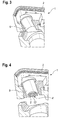
- eine perspektivische Ansicht des Sensorgehäuses mit Ultraschallwand-ler und Hilfsvorrichtung,
- Fig.5
- eine perspektivische Ansicht eines Sensorgehäuses mit einer durch die Vergussmasse fixierten Abschirmhülse, die sich mit Führungselementen an dem Sensorgehäuse abstützt; und
- Fig. 6
- eine perspektivischen Ansicht einer als Abschirmhülse gebildeten Abschirmeinrichtung für ein Piezoelement.
- In
Fig. 1 ist in einem schematischen, vertikalen nicht maßstäblichen Längsschnitt ein Ultraschallsensor 1 mit einem Sensorgehäuse 2 gezeigt. Das Sensorgehäuse 2 ist gabelförmig gebildet und weist einen oberen Gabelarm 16 und einen unteren Gabelarm 17 auf, zwischen denen sich eine Detektionsebene 5 aufspannt, in der zu detektierende Objekte 6 in Form von Etiketten auf einem Bandmaterial angeordnet sind. Der Ultraschallsensor 1 weist einen Ultraschallwandler mit einem Piezoelement 3 und einer Anpassungsschicht 10 auf, das in dem unteren Gabelarm 17 angeordnet ist und als Ultraschallwellen emittierender Sender dient. Ein weiterer Ultraschallwandler mit einem Piezoelement 3' und einer Anpassungsschicht 10' ist in dem oberen Gabelarm 16 angeordnet und dient als Ultraschallwellen empfangender Empfänger. - Das Band- oder Trägermaterial mit den Etiketten liegt in der Detektionsebene 5 und wird in einer Förderrichtung senkrecht zur Bildebene bewegt.
- Eine jeweilige Wandlerfläche 4, 4' ist über jeweils einen Winkel α zu der Detektionseben 5 angeordnet. Durch diese Maßnahme werden Mehrfachreflektionen der Ultraschallwellen an dem Bandmaterial mit Etiketten vermieden.
- Um die Übertragung von Schall von dem Piezoelement 3, 3' auf das Sensorgehäuse 2 zu vermeiden, ist jedes Piezoelement 3, 3' in einer schwingungsdämpfenden und verfestigten Vergussmasse 7 an einem Umfangsflächenbereich 8 des Piezoelementes 3, 3' und an dem Sensorgehäuse 2 abgestützt. In dem gezeigten Ausführungsbeispiel ist jedes Piezoelement 3, 3' auch dichtend mit der Vergussmasse 7 in dem jeweiligen Gabelarm 16, 17 festgelegt, d.h. die Vergussmasse 7 umschließt jedes Piezoelement 3, 3' an seiner jeweiligen Umfangsfläche ganz. Mit der Vergussmasse 7 kann das Schwingungsverhalten des Ultraschallsensors 1 abgestimmt werden.
- Die Vergussmasse 7 kann aus einem Zweikomponenten-Silikon gebildet sein. Es kann auch vorteilhaft sein, ein Epoxyd-System mit oder ohne Füllstoffe zu verwenden.
- Vor dem Einbringen und Verfestigen der Vergussmasse 7 ist in dem in den Figuren 2 bis 5 gezeigten Ausführungsbeispiel zunächst das Sensorgehäuse 2 bzw. der obere und untere Gabelarm 16, 17 mit einer Klebefolie 18, 18' abzudichten, dass die eingebrachte flüssige Vergussmasse 7 nicht wegfließen kann (vgl.
Fig. 2 ). - Danach wird eine Hilfsvorrichtung 9 (hier nur im oberen Gabelarm 16 gezeigt) an einer Gehäuseöffnung 19 zur Aufnahme des Piezoelementes 3 angeordnet. Die Hilfsvorrichtung 9 ist ein für die Vergussmasse 7 formgebender Flächenformkörper, der zudem als Winkelformhilfe zur Einstellung und Festlegung des Winkels α der Wandlerfläche 4 zu der Detektionsebene 5 dient. In dieser Hilfsvorrichtung 9 kann das jeweilige Piezoelement 3 eingesetzt werden (
Fig. 4 ). Es kann auch zusätzlich eine nicht gezeigte Zentrierhülse eingesetzt werden, die die Positionierung des Piezoelementes 3 zu dem Sensorgehäuse 2 übernimmt und sich an der Hilfsvorrichtung 9 abstützen kann. - Nach der Verfestigung der Vergussmasse 7, das auch in einem Autoklaven beschleunigt durch Temperatureinwirkung erfolgen kann, wird die Hilfsvorrichtung 9 entfernt und empfängerseitig am oberen Gabelarm 16 eine Abschirmeinrichtung in eine Aussparung 12 in der Vergussmasse 7 eingesetzt. Das Einbringen und Positionieren der Abschirmeinrichtung in das Sensorgehäuse 2 in Form vorzugsweise einer Abschirmhülse 13 (vgl.
Fig. 5 und Fig. 6 ) kann auch vor dem Einfüllen der Vergussmasse 7 erfolgen. Hier dienen beispielsweise Führungselemente 14, die einstückig mit der Abschirmhülse 13 gebildet sind und sich an korrespondierenden Konturen 15 (vgl.Fig. 5 ) in dem Sensorgehäuse 2 abstützen und die Abschirmhülse 13 in Position halten. Die Führungselemente 14 und Teile der Abschirmhülse 13 können danach von Vergussmasse 7 zumindest teilweise umschlossen und endgültig fixiert werden. - Wie
Fig. 1 zeigt, kann die jeweilige Wandlerfläche 4, 4' des jeweiligen Piezoelementes 3, 3' vollständig von der Vergussmasse 7 umschlossen werden und somit das jeweilige Piezoelement 3, 3' vollständig von der Umgebung isoliert sein. -
- (1)
- Ultraschallsensor
- (2)
- Sensorgehäuse
- (3, 3')
- Piezoelement
- (4, 4')
- Wandlerfläche
- (5)
- Detektionsebene
- (6)
- Objekt
- (7)
- Vergussmasse
- (8)
- Umfangsflächenbereich
- (9)
- Hilfsvorrichtung
- (10, 10')
- Anpassungsschicht
- (12)
- Aussparung
- (13)
- Abschirmhülse
- (14)
- Führungselement
- (15)
- Kontur, v. 2
- (16)
- Gabelarm, oberer
- (17)
- Gabelarm, unterer
- (18, 18')
- Klebefolie
- (19)
- Gehäuseöffnung
- (α)
- Winkel
Claims (15)
- Ultraschallsensor mit einem Sensorgehäuse (2), in dem ein Ultraschallwandler, mit einem Winkel (a) seiner Wandlerfläche (4, 4') zu einer Detektionsebene (5) für Objekte (6) festgelegt ist, dadurch gekennzeichnet, dass der Ultraschallwandler mittels einer aus dem flüssigen Zustand in einen elastischen oder festen Zustand überführten Vergussmasse (7) an dem Sensorgehäuse (2) festgelegt ist, und sich die Vergussmasse (7) an einem Umfangsflächenbereich (8) des Ultraschallwandlers und an dem Sensorgehäuse (2) abstützt.
- Ultraschallsensor nach Anspruch 1, dadurch gekennzeichnet, dass der Ultraschallwandler mit Hilfe der Vergussmasse (7) dichtend in dem Sensorgehäuse (2) festgelegt ist.
- Ultraschallsensor nach Anspruch 1 oder 2, dadurch gekennzeichnet, dass der Ultraschallwandler mit Hilfe einer Hilfsvorrichtung (9) in dem Sensorgehäuse (2) vor dem Einfüllen und Verfestigen der Vergussmasse (7) gehalten ist, und die Hilfsvorrichtung (9) den Winkel (a) der Wandlerfläche (4, 4') zu der Detektionsebene (5) definiert.
- Ultraschallsensor nach Anspruch 3, dadurch gekennzeichnet, dass zusätzlich zu der Hilfsvorrichtung (9) eine Zentrierhülse zur Positionierung des Ultraschallwandlers an dem Sensorgehäuse (2) vorgesehen ist, und dass die Zentrierhülse nach dem Positionieren des Ultraschallwandlers von dem Sensorgehäuse (2) und dem Ultraschallwandler entfernt ist.
- Ultraschallsensor nach Anspruch 3 oder 4, dadurch gekennzeichnet, dass die Hilfsvorrichtung (9) vor Eingießen der Vergussmasse (7) von dem Ultraschallwandler und dem Sensorgehäuse (2) entfernt ist.
- Ultraschallsensor nach einem der Ansprüche 3 bis 5, dadurch gekennzeichnet, dass der Ultraschallwandler zusätzlich mit Hilfe einer Klebung vor dem Einbringen der Vergussmasse (7) zwischen dem Ultraschallwandler und dem Sensorgehäuse (2) an dem Sensorgehäuse (2) gehalten ist.
- Ultraschallsensor nach einem der Ansprüche 1 bis 6, dadurch gekennzeichnet, dass der Ultraschallwandler von einer Abschirmeinrichtung umgeben ist.
- Ultraschallsensor nach Anspruch 7, dadurch gekennzeichnet, dass die Abschirmeinrichtung vor oder nach dem Verfestigen der Vergussmasse (7) um den Ultraschallwandler angeordnet ist.
- Ultraschallsensor nach Anspruch 8, dadurch gekennzeichnet, dass die Abschirmeinrichtung in eine Aussparung (12) der verfestigten Vergussmasse (7) eingebracht ist.
- Ultraschallsensor nach einem der Ansprüche 7 bis 9, dadurch gekennzeichnet, dass die Abschirmeinrichtung als Abschirmhülse (13) mit einstückig daran gebildeten Führungselementen (14) zur Führung und Positionierung der Abschirmhülse (13) an dem Sensorgehäuse (2) gebildet ist.
- Ultraschallsensor nach Anspruch 10, dadurch gekennzeichnet, dass die Abschirmeinrichtung eine Codierung aufweist.
- Ultraschallsensor nach einem der Ansprüche 1 bis 11, dadurch gekennzeichnet, dass die Wandlerfläche (4. 4') des Ultraschallwandlers mit Hilfe der Form der Hilfsvorrichtung (9) und einer Kontur (15) des Sensorgehäuses (2), an der die Hilfsvorrichtung (9) zu liegen kommt, gegenüber der Detektionsebene (5) ausgerichtet ist.
- Ultraschallsensor nach einem der Ansprüche 1 bis 12, dadurch gekennzeichnet, dass der Winkel (a) 1° bis 20° beträgt.
- Ultraschallsensor nach einem der Anspruch 1 bis 13, dadurch gekennzeichnet, dass die Vergussmasse (7) aus einem Elastomer- oder Thermoplast- oder Duroplast-Werkstoff gebildet ist und durch Polykondensation, Polymerisation, Polyaddition oder Trocknung verfestigt ist.
- Ultraschallsensor nach einem der Ansprüche 1 bis 14, dadurch gekennzeichnet, dass der Ultraschallsensor (1) eine Resonanzfrequenz von 300 bis 500 kHz aufweist, und/oder dass die Vergussmasse (7) bei einer Temperatur von etwa - 20° C eine Dämpfung der Ultraschallwellen von mindestens 40 dB bewirkt.
Applications Claiming Priority (1)
| Application Number | Priority Date | Filing Date | Title |
|---|---|---|---|
| DE202020100871.4U DE202020100871U1 (de) | 2020-02-18 | 2020-02-18 | Ultraschallsensor |
Publications (2)
| Publication Number | Publication Date |
|---|---|
| EP3868481A1 true EP3868481A1 (de) | 2021-08-25 |
| EP3868481B1 EP3868481B1 (de) | 2023-06-07 |
Family
ID=73138636
Family Applications (1)
| Application Number | Title | Priority Date | Filing Date |
|---|---|---|---|
| EP20205823.6A Active EP3868481B1 (de) | 2020-02-18 | 2020-11-05 | Ultraschallsensor |
Country Status (2)
| Country | Link |
|---|---|
| EP (1) | EP3868481B1 (de) |
| DE (1) | DE202020100871U1 (de) |
Cited By (1)
| Publication number | Priority date | Publication date | Assignee | Title |
|---|---|---|---|---|
| CN119257641A (zh) * | 2024-10-21 | 2025-01-07 | 苏州冰原科技有限公司 | 超声换能器、生成多超声切面图像的ice超声探头和设备 |
Citations (5)
| Publication number | Priority date | Publication date | Assignee | Title |
|---|---|---|---|---|
| DE19927797C1 (de) * | 1999-06-18 | 2000-12-07 | Fraunhofer Ges Forschung | Ultraschallwandler und Verfahren zu seiner Herstellung |
| US20100071472A1 (en) * | 2008-09-25 | 2010-03-25 | Denso Corporation | Mounting structure of ultrasonic sensor |
| DE102009046144A1 (de) * | 2009-10-29 | 2011-05-19 | Robert Bosch Gmbh | Ultraschallwandler zum Einsatz in einem fluiden Medium |
| WO2011085872A2 (de) * | 2010-01-18 | 2011-07-21 | Robert Bosch Gmbh | Ultraschallwandler zum einsatz in einem fluiden medium |
| EP3101441A1 (de) * | 2015-06-03 | 2016-12-07 | Pepperl + Fuchs GmbH | Ultraschallwandler |
-
2020
- 2020-02-18 DE DE202020100871.4U patent/DE202020100871U1/de active Active
- 2020-11-05 EP EP20205823.6A patent/EP3868481B1/de active Active
Patent Citations (5)
| Publication number | Priority date | Publication date | Assignee | Title |
|---|---|---|---|---|
| DE19927797C1 (de) * | 1999-06-18 | 2000-12-07 | Fraunhofer Ges Forschung | Ultraschallwandler und Verfahren zu seiner Herstellung |
| US20100071472A1 (en) * | 2008-09-25 | 2010-03-25 | Denso Corporation | Mounting structure of ultrasonic sensor |
| DE102009046144A1 (de) * | 2009-10-29 | 2011-05-19 | Robert Bosch Gmbh | Ultraschallwandler zum Einsatz in einem fluiden Medium |
| WO2011085872A2 (de) * | 2010-01-18 | 2011-07-21 | Robert Bosch Gmbh | Ultraschallwandler zum einsatz in einem fluiden medium |
| EP3101441A1 (de) * | 2015-06-03 | 2016-12-07 | Pepperl + Fuchs GmbH | Ultraschallwandler |
Cited By (1)
| Publication number | Priority date | Publication date | Assignee | Title |
|---|---|---|---|---|
| CN119257641A (zh) * | 2024-10-21 | 2025-01-07 | 苏州冰原科技有限公司 | 超声换能器、生成多超声切面图像的ice超声探头和设备 |
Also Published As
| Publication number | Publication date |
|---|---|
| DE202020100871U1 (de) | 2020-11-11 |
| EP3868481B1 (de) | 2023-06-07 |
Similar Documents
| Publication | Publication Date | Title |
|---|---|---|
| DE102008055123B3 (de) | Ultraschallwandler zum Einsatz in einem fluiden Medium | |
| EP0766071B1 (de) | Ultraschallwandler | |
| DE3787677T2 (de) | Ungerichteter Ultraschallwandler. | |
| EP1413858B1 (de) | Ultraschallmassendurchflussmesser | |
| DE102009046148A1 (de) | Ultraschallwandler zum Einsatz in einem fluiden Medium | |
| EP2857803A1 (de) | Ultraschalldurchflussmengenmesseinheit und verfahren zur herstellung davon | |
| DE102009046144A1 (de) | Ultraschallwandler zum Einsatz in einem fluiden Medium | |
| DE102008055126A1 (de) | Ultraschallwandler zum Einsatz in einem fluiden Medium | |
| EP3665445B1 (de) | Spule sowie messwandler mit einer solchen spule | |
| DE102008017067B4 (de) | Elektroakustische Wandleranordnung | |
| DE102017205375A1 (de) | Schallwandler | |
| EP3868481B1 (de) | Ultraschallsensor | |
| EP1687594B1 (de) | Ultraschall-durchflussmessvorrichtung | |
| DE102007037088A1 (de) | Ultraschallwandler mit Anpasskörper und Zwischenschicht | |
| WO2000079513A1 (de) | Dämpfende halterung für das gehäuse eines ultraschallwandlers und verfahren zur herstellung | |
| EP0749005A2 (de) | Schallwandler | |
| EP2850398B1 (de) | Verfahren zur herstellung eines ultraschall-wandlerkerns mit eingebettetem piezoelektrischem wandlerelement | |
| EP1040365B1 (de) | Ultraschallsensor | |
| DE202013101798U1 (de) | Ultraschalldurchflussmessvorrichtung zur Montage eines Ultraschallwandlers | |
| DE102016115199B4 (de) | Ultraschallsensor zur Bestimmung oder Überwachung einer Prozessgröße eines Mediums in der Automatisierungstechnik | |
| EP1902789B1 (de) | Ultraschallwandler und Ultraschallsensor | |
| DE10106477C2 (de) | Ultraschallwandler mit Gehäuse | |
| DE202011101455U1 (de) | Messrohr für einen Ultraschall-Durchflussmesser und Ultraschall-Durchflussmesser | |
| EP3700683B1 (de) | Ultraschallwandler mit zumindest einem piezo-elektrischen oszillator | |
| DE102008055031A1 (de) | Messsystem mit mindestens einem Ultraschallsender und mindestens zwei Ultraschallempfängern |
Legal Events
| Date | Code | Title | Description |
|---|---|---|---|
| PUAI | Public reference made under article 153(3) epc to a published international application that has entered the european phase |
Free format text: ORIGINAL CODE: 0009012 |
|
| STAA | Information on the status of an ep patent application or granted ep patent |
Free format text: STATUS: REQUEST FOR EXAMINATION WAS MADE |
|
| 17P | Request for examination filed |
Effective date: 20210610 |
|
| AK | Designated contracting states |
Kind code of ref document: A1 Designated state(s): AL AT BE BG CH CY CZ DE DK EE ES FI FR GB GR HR HU IE IS IT LI LT LU LV MC MK MT NL NO PL PT RO RS SE SI SK SM TR |
|
| GRAP | Despatch of communication of intention to grant a patent |
Free format text: ORIGINAL CODE: EPIDOSNIGR1 |
|
| STAA | Information on the status of an ep patent application or granted ep patent |
Free format text: STATUS: GRANT OF PATENT IS INTENDED |
|
| GRAS | Grant fee paid |
Free format text: ORIGINAL CODE: EPIDOSNIGR3 |
|
| INTG | Intention to grant announced |
Effective date: 20230403 |
|
| GRAA | (expected) grant |
Free format text: ORIGINAL CODE: 0009210 |
|
| STAA | Information on the status of an ep patent application or granted ep patent |
Free format text: STATUS: THE PATENT HAS BEEN GRANTED |
|
| RBV | Designated contracting states (corrected) |
Designated state(s): DE |
|
| AK | Designated contracting states |
Kind code of ref document: B1 Designated state(s): DE |
|
| REG | Reference to a national code |
Ref country code: DE Ref legal event code: R096 Ref document number: 502020003572 Country of ref document: DE |
|
| REG | Reference to a national code |
Ref country code: DE Ref legal event code: R097 Ref document number: 502020003572 Country of ref document: DE |
|
| PLBE | No opposition filed within time limit |
Free format text: ORIGINAL CODE: 0009261 |
|
| STAA | Information on the status of an ep patent application or granted ep patent |
Free format text: STATUS: NO OPPOSITION FILED WITHIN TIME LIMIT |
|
| 26N | No opposition filed |
Effective date: 20240308 |
|
| PGFP | Annual fee paid to national office [announced via postgrant information from national office to epo] |
Ref country code: DE Payment date: 20251119 Year of fee payment: 6 |