EP3868314A1 - Chirurgisches schneidinstrument mit distaler saugfunktion - Google Patents
Chirurgisches schneidinstrument mit distaler saugfunktion Download PDFInfo
- Publication number
- EP3868314A1 EP3868314A1 EP21169129.0A EP21169129A EP3868314A1 EP 3868314 A1 EP3868314 A1 EP 3868314A1 EP 21169129 A EP21169129 A EP 21169129A EP 3868314 A1 EP3868314 A1 EP 3868314A1
- Authority
- EP
- European Patent Office
- Prior art keywords
- cutting blade
- cutting
- suction
- inner cutting
- distal end
- Prior art date
- Legal status (The legal status is an assumption and is not a legal conclusion. Google has not performed a legal analysis and makes no representation as to the accuracy of the status listed.)
- Pending
Links
- 238000005520 cutting process Methods 0.000 title claims abstract description 394
- 238000000034 method Methods 0.000 claims description 19
- 239000000463 material Substances 0.000 claims description 16
- 239000012530 fluid Substances 0.000 claims description 11
- 239000007788 liquid Substances 0.000 claims description 11
- 210000001519 tissue Anatomy 0.000 description 27
- 238000001356 surgical procedure Methods 0.000 description 11
- 210000000988 bone and bone Anatomy 0.000 description 5
- 230000002262 irrigation Effects 0.000 description 4
- 238000003973 irrigation Methods 0.000 description 4
- 238000001574 biopsy Methods 0.000 description 3
- 238000003780 insertion Methods 0.000 description 3
- 230000037431 insertion Effects 0.000 description 3
- 239000002184 metal Substances 0.000 description 3
- 229910001220 stainless steel Inorganic materials 0.000 description 3
- 239000010935 stainless steel Substances 0.000 description 3
- 208000014674 injury Diseases 0.000 description 2
- 230000008733 trauma Effects 0.000 description 2
- 239000004020 conductor Substances 0.000 description 1
- 230000007794 irritation Effects 0.000 description 1
- 239000000615 nonconductor Substances 0.000 description 1
- 230000000399 orthopedic effect Effects 0.000 description 1
- 238000010079 rubber tapping Methods 0.000 description 1
Images


Classifications
-
- A—HUMAN NECESSITIES
- A61—MEDICAL OR VETERINARY SCIENCE; HYGIENE
- A61B—DIAGNOSIS; SURGERY; IDENTIFICATION
- A61B10/00—Other methods or instruments for diagnosis, e.g. instruments for taking a cell sample, for biopsy, for vaccination diagnosis; Sex determination; Ovulation-period determination; Throat striking implements
- A61B10/02—Instruments for taking cell samples or for biopsy
- A61B10/0233—Pointed or sharp biopsy instruments
- A61B10/0266—Pointed or sharp biopsy instruments means for severing sample
- A61B10/0275—Pointed or sharp biopsy instruments means for severing sample with sample notch, e.g. on the side of inner stylet
-
- A—HUMAN NECESSITIES
- A61—MEDICAL OR VETERINARY SCIENCE; HYGIENE
- A61B—DIAGNOSIS; SURGERY; IDENTIFICATION
- A61B10/00—Other methods or instruments for diagnosis, e.g. instruments for taking a cell sample, for biopsy, for vaccination diagnosis; Sex determination; Ovulation-period determination; Throat striking implements
- A61B10/02—Instruments for taking cell samples or for biopsy
- A61B10/0233—Pointed or sharp biopsy instruments
- A61B10/0283—Pointed or sharp biopsy instruments with vacuum aspiration, e.g. caused by retractable plunger or by connected syringe
-
- A—HUMAN NECESSITIES
- A61—MEDICAL OR VETERINARY SCIENCE; HYGIENE
- A61B—DIAGNOSIS; SURGERY; IDENTIFICATION
- A61B17/00—Surgical instruments, devices or methods, e.g. tourniquets
- A61B17/16—Bone cutting, breaking or removal means other than saws, e.g. Osteoclasts; Drills or chisels for bones; Trepans
- A61B17/1604—Chisels; Rongeurs; Punches; Stamps
-
- A—HUMAN NECESSITIES
- A61—MEDICAL OR VETERINARY SCIENCE; HYGIENE
- A61B—DIAGNOSIS; SURGERY; IDENTIFICATION
- A61B17/00—Surgical instruments, devices or methods, e.g. tourniquets
- A61B17/32—Surgical cutting instruments
- A61B17/320016—Endoscopic cutting instruments, e.g. arthroscopes, resectoscopes
- A61B17/32002—Endoscopic cutting instruments, e.g. arthroscopes, resectoscopes with continuously rotating, oscillating or reciprocating cutting instruments
- A61B2017/320024—Morcellators, e.g. having a hollow cutting tube with an annular cutter for morcellating and removing tissue
-
- A—HUMAN NECESSITIES
- A61—MEDICAL OR VETERINARY SCIENCE; HYGIENE
- A61B—DIAGNOSIS; SURGERY; IDENTIFICATION
- A61B2217/00—General characteristics of surgical instruments
- A61B2217/002—Auxiliary appliance
- A61B2217/005—Auxiliary appliance with suction drainage system
Definitions
- This disclosure relates to surgical instruments, and in particular to surgical cutting instruments that use suction, for example, powered shavers, microdebriders and dissector blades.
- Surgical apparatus used to shave, cut, resect, abrade and/or remove tissue, bone and/or other bodily materials are known.
- Such surgical apparatus can include a cutting surface, such as a rotating blade disposed on an elongated inner tube that is rotated within an elongated outer tube having a cutting window.
- the inner and outer tubes together form a surgical cutting instrument or unit.
- the elongated outer tube includes a distal end defining an opening or cutting window disposed at a side of the distal end of the outer tube.
- the cutting window of the outer tube exposes the cutting surface of the inner tube (located at a side of the distal end of the inner tube) to tissue, bone and/or any other bodily materials to be removed.
- a powered handpiece is used to rotate the inner tube with respect to the outer tube while an outer tube hub (connected to the proximal end of the outer tube) is fixed to the handpiece and an inner tube hub (connected to the proximal end of the inner tube) is loosely held in place by the powered handpiece.
- the inner tube is hollow and has a cutting window on a side surface of its distal end such that tissue, bone, etc. will be cut or shaved as the cutting window of the inner tube aligns with and then becomes misaligned with the cutting window of the outer tube as the inner tube is rotated within the outer tube.
- the cutting device nibbles or takes away small pieces of the bone, tissue, etc. as the inner tube is rotated within the outer tube.
- a vacuum is applied through the inner tube such that the bodily material that is to be cut, shaved, etc. is drawn into the windows of the inner and outer tubes when those windows become aligned, thereby facilitating the cutting, shaving, etc. of the tissue, which then travels through the inner tube due to the suction.
- an irrigation fluid which can include a liquid, to the surgical site via a passage provided between the inner and outer tubes.
- US 2005/096649 A1 discloses a surgical micro-resecting instrument including an outer tubular member, an inner tubular member, a hub assembly and an electrical insulator.
- the outer tubular member is formed of an electrically conductive material and defines a proximal section, a distal section and a lumen.
- the inner tubular member is disposed within the lumen and defines a distal portion that forms a cutting tip.
- GB 2 042 902 A discloses a surgical instrument for remote cutting which comprises coaxial inner and outer tubes, the inner tube being rotatably driven whilst the outer tube is stationary.
- the inner and outer tubes have windows in their side walls at their distal ends providing diverging cutting edges.
- US 5 112 299 A discloses an arthroscopic surgery instrument which includes an elongated outer sheath member having substantially fully open distal and proximal ends, and an inner hollow cylindrical cutting blade member rotatable within the sheath member.
- An aspirator communicates with the interior space of the cutting blade member to remove tissue severed by the co-operable cutting action of the blade and sheath members.
- US 6 419 684 B1 discloses an end-cutting arthroscopic shaver blade having a tubular inner member rotatable within a tubular outer member.
- the distal ends of each of the tubular members are provided with at least two notches each of which has longitudinally extending sides provided with cutting edges.
- US 2005/070818 A1 discloses a biopsy device suitable for collection of a tissue sample from a biopsy site in a body lumen.
- the biopsy device in comprises a combination of an introducer assembly, a cutter assembly, and an endoscope assembly that coact with one another.
- the introducer assembly includes a hollow sheath having a distal end portion defining an aperture suitable for receiving a tissue mass therein.
- the cutter assembly includes a cutter tube having a distal end portion with a cutting edge. The cutter tube is sized to fit axially within the introducer sheath.
- the surgeon wishes to apply suction to the surgical site without performing cutting with the surgical instrument. This usually is done by withdrawing the surgical instrument and inserting a dedicated suction device (for example, a suction wand which is a tube to which suction is applied).
- a dedicated suction device for example, a suction wand which is a tube to which suction is applied.
- exchanging the surgical tool for the dedicated suction device is time-consuming.
- insertion and removal of instruments into the patient can cause trauma and irritation to the passage of the patient, and thus it is desirable to minimize the number of times that surgical instruments need to be withdrawn and inserted/reinserted into the patient.
- the surgeon can use the surgical cutting instrument as a suction device, for example, by stopping rotation of the inner cutting tube while continuing to apply suction through the inner tube.
- the pedal or other control device which controls the rotation of the inner tube
- the surgeon can cause the cutting windows of the inner and outer tubes to be aligned with each other such that suction can be applied to the surgical site through the aligned windows of the inner and outer tubes.
- the windows of the inner and outer tubes are cutting surfaces (and typically include serrations)
- most surgeons choose not to use the surgical cutting tool as a suctioning device because tissue adjacent to the outer tube window tends to be drawn into the window and partially cut and/or irritated by the cutting surfaces of the inner and outer tubes.
- the suction is applied from the side of the distal end of the tube, which is not optimal.
- Most suction wands apply the suction from the very end of the tip such that suction is applied at the very tip of the suction wand.
- a surgical instrument that performs cutting also can function as a suction wand. This is achieved by providing the surgical instrument with a suction aperture at the distal-most tip of the surgical instrument such that a longitudinal axis of the surgical instrument passes through the suction aperture.
- the surgical instrument includes a first cutting blade and a second cutting blade.
- the first cutting blade includes a tubular body having a proximal end and a distal end, with a cutting window disposed at a side of the first cutting blade near the distal end.
- the second cutting blade includes a tubular body having a proximal end and a distal end, with a cutting window disposed at a side of the second cutting blade near the distal end.
- the second cutting blade is rotatably disposed inside of the first cutting blade such that the surgical instrument cuts tissue by rotating the second cutting blade within the first cutting blade while a vacuum is applied through an internal bore of the second cutting blade to draw the tissue into the cutting windows of the first and second cutting blades and sever the tissue by rotation of the second cutting blade.
- the distal end of the first cutting blade includes a first suction aperture through which a longitudinal axis of the first cutting blade extends.
- the distal end of the second cutting blade includes a second suction aperture through which a longitudinal axis of the second cutting blade extends.
- the surgical instrument can be used as a suction tool by applying the vacuum through the internal bore of the second cutting blade while the second cutting blade is stopped from rotating with the cutting windows of the first and second cutting blades misaligned with each other so that the vacuum is applied through the first and second suction apertures.
- most of the suction is applied through the cutting windows because they are located closer to the vacuum source than are the suction apertures (that is, the cutting windows are proximal to the suction apertures).
- the cutting operation can be performed as usual.
- a diameter of the first suction aperture is equal to or smaller than a diameter of the second suction aperture.
- the first and second cutting blades preferably are made from a sterilizable material.
- the sterilizable material is a metal such as stainless steel.
- a surgical method includes inserting the surgical instrument described above into a passage of a patient and then performing a suctioning operation with the surgical instrument.
- the suctioning operation includes positioning the second cutting blade relative to the first cutting blade so that the cutting windows of the first and second cutting blades are misaligned with each other so that the internal bore of the second cutting blade does not communicate with the passage of the patient through either of the cutting windows of the first and second cutting blades.
- the method further includes applying a vacuum through the internal bore of the second cutting blade to draw material from the passage of the patient into the internal bore of the second cutting blade through the first and second suction apertures. The first and second cutting blades are not rotated relative to each other during the suctioning operation.
- the second cutting blade can be positioned relative to the first cutting blade so that the cutting windows of the first and second cutting blades are misaligned with each other by the surgeon operating the controls of the surgical instrument (for example, by operating a foot pedal) while observing the distal tip of the cutting instrument (for example, with an endoscope as is typically used to observe the surgical procedure) until the cutting window of the inner, second cutting blade is misaligned with the cutting window of the outer, first cutting blade such that the back side of the second cutting blade opposite to the window substantially blocks the window of the first cutting blade.
- the method of suctioning can be performed after the surgical instrument has been used for cutting and/or before the surgical instrument has been used for cutting. In either case, it is unnecessary to withdraw the cutting instrument when switching between a cutting operation and a suctioning operation. Furthermore, a separate suction wand may not be needed.
- Fig. 1 is a schematic of a powered surgical tool system. Except for the tip of the cutting tool, to be described hereafter, the system may be in accordance with the system described in U.S. Patent No. 7,247,161 , the disclosure of which is incorporated herein by reference in its entirety. Another system to which the invention is applicable is described in U.S. Patent No. 7,318,831 , the disclosure of which is incorporated herein by reference in its entirety.
- the powered surgical tool system 1 includes a handle 2, a footswitch 4 (with pedal 12), fluid (liquid and/or gas) source 22, suction source 28, a control unit 6, fluid pump 5 and a fluid inlet/irrigation outlet 7.
- the system is supplied with power from a power source 16 such as a wall outlet.
- the suction source 28 may be an external suction source such as provided by attachment to a facility suction outlet provided on a wall.
- the handle 2 is connected, at its distal end, to a surgical instrument 8.
- the surgical instrument 8 in this embodiment includes a cutting tip at its distal end 8A that is used, for example, to cut, shave, remove, resect and/or abrade tissue, bone and/or other bodily materials.
- Fig. 2 illustrates a perspective view of an exemplary embodiment of the surgical instrument 8 in accordance with aspects of the invention.
- the instrument 8 incorporates an inner tube 9 and an outer tube 10.
- an inner tube hub 13 is formed on the second end 14 of the inner tube 9 and an outer tube hub 15 is formed on the second end 17 of the outer tube 10.
- the inner tube 9 is inserted into a fluid passage 20 formed within the outer tube 10 so that the inner tube 9 is co-axially disposed within the outer tube 10 until the external distal tip of the inner tube 9 contacts the internal distal surface of the outer tube 10.
- the outer tube 10 has a larger diameter than the inner tube 9, thus allowing for insertion of the inner tube 9 within the outer tube 10.
- the inner and outer tubes will be pre-assembled prior to delivery to the customer. Thus, a customer will most likely not be inserting the inner tube into the outer tube.
- the inner and outer tube hubs 13, 15 couple the inner and outer tubes 9, 10, respectively, to the handle 2. Once coupled to the handle 2, the outer tube 10 will be fixed relative to the handle 2, but the inner tube 9 will be rotatable relative to the outer tube 10 and the handle 2.
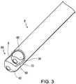
- Fig. 3 is a perspective view of the distal tip 8a of the surgical instrument 8.
- Fig. 3 shows the inner tube 9 retracted slightly from its usual position so that the structure of the distal tips of both the inner tube 9 and the outer tube 10 can be more readily seen.
- the outer tube 10 includes a cutting window 60 disposed at a side of its distal end.
- the outer tube 10 also can be referred to as a first cutting blade.
- the inner tube 9 also includes a cutting window 30 disposed at a side of its distal end.
- the inner tube 9 also can be referred to as a second cutting blade.
- the edges of the cutting windows 30 and 60 can be serrated, smooth or a combination of serrated and smooth to form cutting surfaces.
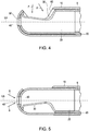
- Each of the inner and outer tubes 9, 10 also includes a suction aperture at its distal end as shown even more clearly in Figs. 4 and 5 .
- the inner cutting blade 9 rotates within the outer cutting blade 10, and thus as the inner cutting blade 9 rotates, the cutting windows 30 and 60 become aligned with each other as shown in Fig. 4 and then become misaligned with each other as shown in Fig. 5 .
- the side of the inner tube 9 distal tip opposite from the cutting window 30 blocks the cutting window 60 of the outer cutting blade 10, as will be described in more detail below.
- the first, or outer cutting blade 10 thus is a tubular body having a proximal end and a distal end, with a cutting window 60 disposed at a side of the first cutting blade 10 near the distal end.
- the outer cutting blade 10 also includes a suction aperture 40 at its distal-most end through which a longitudinal axis LA of the outer tube cutting blade 10 extends.
- the inner, second cutting blade 9 is a tubular body having a proximal end and a distal end, with cutting window 30 disposed at a side of its distal end.
- the second, inner cutting blade 9 is rotatably disposed inside of the first, outer cutting blade 10 such that the surgical instrument 8 cuts tissue by rotating the second, inner cutting blade 9 within the first, outer cutting blade 10 while a vacuum is applied through an internal bore 25 of the cutting blade 9 to draw the tissue into the cutting windows 30 and 60 of the cutting blades 9 and 10 and sever the tissue by rotation of the cutting blade 9.
- the inner cutting blade 9 also includes a suction aperture 50 at its distal-most end through which a longitudinal axis LA of the inner tube cutting blade 9 extends.
- the surgical instrument 8 can be used as a suction tool by applying the vacuum through the internal bore 25 of the cutting blade 9 while the cutting blade 9 is stopped from rotating and the cutting windows 30 and 60 of the cutting blades 9 and 10 are misaligned with each other as shown in Fig. 5 so that the vacuum is applied through a suction passage defined by the first and second suction apertures 40 and 50.
- the surgeon operating the instrument 8 can cause the windows 30 and 60 to become oriented in the misaligned state shown in Fig. 5 by, for example, tapping on the pedal 12 that controls the instrument to cause incremental rotation of the inner cutting blade 9 while observing the distal tip of the instrument, for example, by an endoscope, which usually also is disposed at the operating site, until the windows 30 and 60 obtain the state shown in Fig.
- irrigation fluid also could be supplied through bore 20 when in the state shown in Fig. 5 .
- the suction apertures 40 and 50 it is undesirable for the suction apertures 40 and 50 to function like a cutting element (like the cutting windows 30 and 60).
- the diameter of the suction aperture 40 provided on the outer cutting blade 10 be equal to or smaller than a diameter of the suction aperture 50 provided on the inner cutting blade 9.
- suction aperture 40 By making the diameter of the inner suction aperture (aperture 50) on the rotating cutting blade 9 equal to or larger than the diameter of the outer suction aperture (suction aperture 40), the suction apertures 40 and 50 will not function as a cutting device because tissue will not be pinched between the two apertures 40 and 50, or otherwise cut or damaged by those apertures when the instrument is being used as a suction wand and when the instrument is being used as a cutting tool with the inner blade 9 rotating.
- suction aperture 40 is smaller than suction aperture 50.
- the edges of the apertures 40 and 50 also can be rounded to further keep them from cutting tissue. However, the apertures do not cut tissue even if they are not rounded.
- the apertures 40 and 50 do not function to cut tissue is because the apertures 40 and 50 remain aligned with each other even while the inner cutting blade 9 rotates. Due to such alignment, the open suction passage (defined by apertures 40 and 50) exists between the internal bore 25 and an area external of the surgical instrument (that is, an area distal of the surgical instrument tip) through the suction apertures 40 and 50 both when the cutting blade 9 does not rotate and when the cutting blade 9 rotates within the cutting blade 10. In this regard, the suction aperture 50 at the distal end of the inner cutting blade 9 remains in fluid communication with the suction aperture 40 at the distal end of the outer cutting blade 10 as the inner cutting blade 9 rotates, and when it is stationary.
- the distal ends of the cutting blades 9 and 10 are substantially spherical.
- the distal ends of the blades 9 and 10 could be flat, with the first and second apertures 40 and 50 being disposed on flat portions of those blades.
- spherical tips are preferred to ease insertion into the patient.
- the cutting blades 9 and 10 are made from a sterilizable material.
- the sterilizable material is a metal such as stainless steel.
- the surgical instrument 8 When the instrument 8 is used for surgery, the surgical instrument 8 is inserted into a passage of a patient. Either before or after (or both before and after) a cutting operation is performed, the surgical instrument 8 can be used to perform a suctioning operation.
- the suctioning operation includes positioning the inner blade 9 relative to the outer blade 10 so that the cutting windows 30 and 60 are misaligned with each other so that the internal bore 25 of the cutting blade 9 does not communicate with the passage of the patient into which the surgical instrument is inserted through either of the cutting windows 30 and 60.
- a vacuum applied through the internal bore 25 of the inner cutting blade 9 draws material from the passage of the patient into the internal bore 25 through the suction passage defined by the first and second suction apertures 40 and 50.
- the inner cutting blade 9 is not rotated relative to outer cutting blade 10.
- the inner and outer cutting blades 9 and 10 are straight.
- the surgical instrument 8 can have one or more bends in it such that it is not straight.
- the inner cutting blade 9 would be flexible.
- Flexible hollow cutting blades are known and used with curved cutting instruments. See, for example, U.S. Patent No. 4,646,738 , the disclosure of which is incorporated herein by reference in its entirety, and see, for example, U.S. Patent No. 5,707,350 , the disclosure of which is incorporated herein by reference in its entirety.
- the outer cutting blade 10 included an open distal end defined by a suction aperture 40 formed through an otherwise closed portion at the distal tip of the outer cutting blade 10.
- the open distal end of the outer cutting blade 10 could be formed by providing an open-ended outer cutting blade 10 (rather than a closed portion having an aperture formed through it). That is, the opening provided at the distal end of the outer cutting blade 10 need not be an aperture that is completely surrounded by wall structure of the outer cutting blade, but instead could be only partially surrounded by wall structure of the outer cutting blade.
- the suction aperture 40 does need to be perfectly circular, but could have other shapes.
- FIG. 4 Another option would be to form the surgical instrument with no suction aperture at the distal end of the inner cutting blade 9, but to only provide a suction aperture through the distal end of the outer cutting blade 10 at a location that is offset from the longitudinal axis LA.
- Such a suction aperture would be disposed so as to be covered by and closed by the inner cutting blade 9 when the cutting windows are aligned with each other (the Fig. 4 orientation), but would be uncovered by the distal tip portion of the inner cutting blade 9 when the cutting windows of the inner and outer cutting blades 9 and 10 are misaligned with each other (the Fig. 5 orientation).
- a structure is disfavored because it is feared that the suction aperture in the outer cutting blade will function to cut tissue when the inner cutting blade is rotating within the outer cutting blade (i.e., during a cutting operation).
Landscapes
- Health & Medical Sciences (AREA)
- Life Sciences & Earth Sciences (AREA)
- Surgery (AREA)
- Animal Behavior & Ethology (AREA)
- Medical Informatics (AREA)
- Veterinary Medicine (AREA)
- Public Health (AREA)
- Engineering & Computer Science (AREA)
- Biomedical Technology (AREA)
- Heart & Thoracic Surgery (AREA)
- General Health & Medical Sciences (AREA)
- Molecular Biology (AREA)
- Nuclear Medicine, Radiotherapy & Molecular Imaging (AREA)
- Orthopedic Medicine & Surgery (AREA)
- Pathology (AREA)
- Dentistry (AREA)
- Oral & Maxillofacial Surgery (AREA)
- Surgical Instruments (AREA)
Applications Claiming Priority (4)
| Application Number | Priority Date | Filing Date | Title |
|---|---|---|---|
| US13/013,240 US8585724B2 (en) | 2011-01-25 | 2011-01-25 | Surgical cutting instrument with distal suction capability |
| EP12701276.3A EP2667794B1 (de) | 2011-01-25 | 2012-01-04 | Chirurgisches schneidinstrument mit distaler saugkapazität |
| PCT/US2012/020171 WO2012102838A1 (en) | 2011-01-25 | 2012-01-04 | Surgical cutting instrument with distal suction capabiilty |
| EP18174405.3A EP3384857B1 (de) | 2011-01-25 | 2012-01-04 | Chirurgisches schneidinstrument mit distaler saugkapazität |
Related Parent Applications (2)
| Application Number | Title | Priority Date | Filing Date |
|---|---|---|---|
| EP12701276.3A Division EP2667794B1 (de) | 2011-01-25 | 2012-01-04 | Chirurgisches schneidinstrument mit distaler saugkapazität |
| EP18174405.3A Division EP3384857B1 (de) | 2011-01-25 | 2012-01-04 | Chirurgisches schneidinstrument mit distaler saugkapazität |
Publications (1)
| Publication Number | Publication Date |
|---|---|
| EP3868314A1 true EP3868314A1 (de) | 2021-08-25 |
Family
ID=45532044
Family Applications (3)
| Application Number | Title | Priority Date | Filing Date |
|---|---|---|---|
| EP12701276.3A Active EP2667794B1 (de) | 2011-01-25 | 2012-01-04 | Chirurgisches schneidinstrument mit distaler saugkapazität |
| EP18174405.3A Active EP3384857B1 (de) | 2011-01-25 | 2012-01-04 | Chirurgisches schneidinstrument mit distaler saugkapazität |
| EP21169129.0A Pending EP3868314A1 (de) | 2011-01-25 | 2012-01-04 | Chirurgisches schneidinstrument mit distaler saugfunktion |
Family Applications Before (2)
| Application Number | Title | Priority Date | Filing Date |
|---|---|---|---|
| EP12701276.3A Active EP2667794B1 (de) | 2011-01-25 | 2012-01-04 | Chirurgisches schneidinstrument mit distaler saugkapazität |
| EP18174405.3A Active EP3384857B1 (de) | 2011-01-25 | 2012-01-04 | Chirurgisches schneidinstrument mit distaler saugkapazität |
Country Status (5)
| Country | Link |
|---|---|
| US (1) | US8585724B2 (de) |
| EP (3) | EP2667794B1 (de) |
| JP (2) | JP5859025B2 (de) |
| CN (1) | CN103327911B (de) |
| WO (1) | WO2012102838A1 (de) |
Families Citing this family (37)
| Publication number | Priority date | Publication date | Assignee | Title |
|---|---|---|---|---|
| US20160001064A1 (en) * | 2005-07-22 | 2016-01-07 | The Spectranetics Corporation | Endocardial lead cutting apparatus |
| IN2012DN01917A (de) | 2009-09-08 | 2015-07-24 | Salient Surgical Tech Inc | |
| US8377086B2 (en) | 2011-01-25 | 2013-02-19 | Gyrus Ent L.L.C. | Surgical cutting instrument with distal suction passage forming member |
| US8425546B2 (en) * | 2011-01-27 | 2013-04-23 | Mi4Spine, Llc | Up cutting knife with suction |
| US8475482B2 (en) | 2011-02-17 | 2013-07-02 | Gyrus Ent L.L.C. | Surgical instrument with distal suction capability |
| US9226792B2 (en) | 2012-06-12 | 2016-01-05 | Medtronic Advanced Energy Llc | Debridement device and method |
| US9173667B2 (en) * | 2012-10-16 | 2015-11-03 | Med-Sonics Corporation | Apparatus and methods for transferring ultrasonic energy to a bodily tissue |
| US9339284B2 (en) | 2012-11-06 | 2016-05-17 | Med-Sonics Corporation | Systems and methods for controlling delivery of ultrasonic energy to a bodily tissue |
| US8956355B2 (en) | 2012-11-30 | 2015-02-17 | Gyrus Acmi, Inc. | Integrated blade assembly and identification circuit |
| US9358036B2 (en) | 2013-03-12 | 2016-06-07 | Gyrus Acmi, Inc. | Blade positioning device |
| US10314647B2 (en) | 2013-12-23 | 2019-06-11 | Medtronic Advanced Energy Llc | Electrosurgical cutting instrument |
| US10813686B2 (en) | 2014-02-26 | 2020-10-27 | Medtronic Advanced Energy Llc | Electrosurgical cutting instrument |
| US20160066945A1 (en) * | 2014-09-08 | 2016-03-10 | Medtronic-Xomed, Inc. | Tumor margin device |
| US9636132B2 (en) | 2014-09-08 | 2017-05-02 | Medtronic Xomed, Inc. | Tumor debulker |
| US9737322B2 (en) | 2014-09-08 | 2017-08-22 | Medtronic Xomed, Inc. | Method for resection of tumors and tissues |
| US20160183962A1 (en) * | 2014-12-17 | 2016-06-30 | Greg Spitz | Apparatus And Methods For Treating Undesired Viens |
| US10376302B2 (en) | 2015-02-18 | 2019-08-13 | Medtronic Xomed, Inc. | Rotating electrical connector for RF energy enabled tissue debridement device |
| AU2016219980B2 (en) | 2015-02-18 | 2020-09-03 | Medtronic Xomed, Inc. | RF energy enabled tissue debridement device |
| US10188456B2 (en) | 2015-02-18 | 2019-01-29 | Medtronic Xomed, Inc. | Electrode assembly for RF energy enabled tissue debridement device |
| US9763684B2 (en) | 2015-04-02 | 2017-09-19 | Med-Sonics Corporation | Devices and methods for removing occlusions from a bodily cavity |
| CN105169548A (zh) * | 2015-09-07 | 2015-12-23 | 王敏 | 一种吸引器及其导流头 |
| US10716612B2 (en) | 2015-12-18 | 2020-07-21 | Medtronic Advanced Energy Llc | Electrosurgical device with multiple monopolar electrode assembly |
| USD802769S1 (en) | 2016-05-16 | 2017-11-14 | Teleflex Medical Incorporated | Thrombectomy handle assembly |
| WO2017218703A1 (en) * | 2016-06-15 | 2017-12-21 | Typenex Medical, Llc | Apparatus and methods for holding controllers or devices |
| AU2017294760B2 (en) * | 2016-07-14 | 2022-07-14 | Stryker European Operations Holdings Llc | Cutting assembly for surgical instrument with clog reducing tip |
| CN106388878A (zh) * | 2016-08-30 | 2017-02-15 | 苏州品诺维新医疗科技有限公司 | 一种动力控制装置及其控制方法、手术操作系统 |
| CN106236197A (zh) * | 2016-08-30 | 2016-12-21 | 苏州品诺维新医疗科技有限公司 | 一种手术器械、操作方法及手术系统 |
| CN111629645A (zh) * | 2017-08-28 | 2020-09-04 | 锐凌公司 | 关节镜装置和方法 |
| US12023082B2 (en) | 2017-10-06 | 2024-07-02 | Medtronic Advanced Energy Llc | Hemostatic thermal sealer |
| CN107998472A (zh) * | 2017-12-28 | 2018-05-08 | 山西阳光中天医疗器械有限公司 | 一种双套式自动吸脂针管及其吸脂方法 |
| US11185345B2 (en) * | 2018-01-31 | 2021-11-30 | Gyrus Acmi, Inc. | Debrider with external irrigation supply channel |
| CN108186059B (zh) * | 2018-03-13 | 2020-07-28 | 湖州市妇幼保健院 | 一种胃肠镜活检摘取装置 |
| CN108378892B (zh) * | 2018-03-19 | 2023-12-15 | 广东工业大学 | 一种微创刨刀 |
| CN109770999B (zh) * | 2019-01-28 | 2024-04-16 | 逸思(苏州)医疗科技有限公司 | 一种手术切割器 |
| USD974558S1 (en) | 2020-12-18 | 2023-01-03 | Stryker European Operations Limited | Ultrasonic knife |
| CN113303876B (zh) * | 2021-06-01 | 2022-09-02 | 南阳市第二人民医院 | 一种旋转机构及医用鼻窦吸引切割器 |
| TWI788915B (zh) * | 2021-07-14 | 2023-01-01 | 國立成功大學 | 用於剃除皮下組織的刀具 |
Citations (10)
| Publication number | Priority date | Publication date | Assignee | Title |
|---|---|---|---|---|
| GB2042902A (en) | 1979-02-21 | 1980-10-01 | Dyonics Inc | Surgical cutting device |
| US4646738A (en) | 1985-12-05 | 1987-03-03 | Concept, Inc. | Rotary surgical tool |
| US5112299A (en) | 1989-10-25 | 1992-05-12 | Hall Surgical Division Of Zimmer, Inc. | Arthroscopic surgical apparatus and method |
| US5707350A (en) | 1990-02-07 | 1998-01-13 | Smith & Nephew Endoscopy Inc. | Surgical instrument |
| US5730752A (en) * | 1996-10-29 | 1998-03-24 | Femrx, Inc. | Tubular surgical cutters having aspiration flow control ports |
| US6419684B1 (en) | 2000-05-16 | 2002-07-16 | Linvatec Corporation | End-cutting shaver blade for axial resection |
| US20050070818A1 (en) | 2003-09-30 | 2005-03-31 | Mueller Richard L. | Biopsy device with viewing assembly |
| US20050096649A1 (en) | 2003-11-04 | 2005-05-05 | Medtronic, Inc. | Surgical micro-resecting instrument with electrocautery and continuous aspiration features |
| US7247161B2 (en) | 2002-03-22 | 2007-07-24 | Gyrus Ent L.L.C. | Powered surgical apparatus, method of manufacturing powered surgical apparatus, and method of using powered surgical apparatus |
| US7318831B2 (en) | 2002-07-13 | 2008-01-15 | Stryker Corporation | System and method for performing irrigated nose and throat surgery |
Family Cites Families (16)
| Publication number | Priority date | Publication date | Assignee | Title |
|---|---|---|---|---|
| US3882872A (en) | 1970-01-05 | 1975-05-13 | Nicholas G Douvas | Method and apparatus for cataract surgery |
| US3937222A (en) | 1973-11-09 | 1976-02-10 | Surgical Design Corporation | Surgical instrument employing cutter means |
| JPS60158851A (ja) * | 1984-01-31 | 1985-08-20 | 持田製薬株式会社 | ロ−タリ−スクレイパ− |
| US4844064A (en) | 1987-09-30 | 1989-07-04 | Baxter Travenol Laboratories, Inc. | Surgical cutting instrument with end and side openings |
| US5674235A (en) | 1995-05-10 | 1997-10-07 | Ultralase Technologies International | Ultrasonic surgical cutting instrument |
| US5665101A (en) * | 1996-04-01 | 1997-09-09 | Linvatec Corporation | Endoscopic or open lipectomy instrument |
| US6342061B1 (en) | 1996-09-13 | 2002-01-29 | Barry J. Kauker | Surgical tool with integrated channel for irrigation |
| US5947983A (en) * | 1998-03-16 | 1999-09-07 | Boston Scientific Corporation | Tissue cutting and stitching device and method |
| US6478805B1 (en) * | 1999-04-16 | 2002-11-12 | Nuvasive, Inc. | System for removing cut tissue from the inner bore of a surgical instrument |
| US6610059B1 (en) | 2002-02-25 | 2003-08-26 | Hs West Investments Llc | Endoscopic instruments and methods for improved bubble aspiration at a surgical site |
| CN100577116C (zh) * | 2004-03-04 | 2010-01-06 | 施特劳勃医疗器械股份公司 | 用于抽吸、粉碎和排出血管内可去除的材料的导管 |
| US7674263B2 (en) * | 2005-03-04 | 2010-03-09 | Gyrus Ent, L.L.C. | Surgical instrument and method |
| US7670299B2 (en) * | 2006-03-07 | 2010-03-02 | Ethincon Endo-Surgery, Inc. | Device for minimally invasive internal tissue removal |
| US8574253B2 (en) * | 2007-04-06 | 2013-11-05 | Hologic, Inc. | Method, system and device for tissue removal |
| US8486097B2 (en) * | 2010-02-04 | 2013-07-16 | Nico Corporation | Tissue cutting device |
| JP2015133275A (ja) * | 2014-01-15 | 2015-07-23 | 株式会社オートネットワーク技術研究所 | 防水コネクタ |
-
2011
- 2011-01-25 US US13/013,240 patent/US8585724B2/en active Active
-
2012
- 2012-01-04 EP EP12701276.3A patent/EP2667794B1/de active Active
- 2012-01-04 EP EP18174405.3A patent/EP3384857B1/de active Active
- 2012-01-04 WO PCT/US2012/020171 patent/WO2012102838A1/en active Application Filing
- 2012-01-04 JP JP2013550487A patent/JP5859025B2/ja not_active Expired - Fee Related
- 2012-01-04 CN CN201280005896.1A patent/CN103327911B/zh not_active Expired - Fee Related
- 2012-01-04 EP EP21169129.0A patent/EP3868314A1/de active Pending
-
2015
- 2015-07-02 JP JP2015133275A patent/JP5980383B2/ja not_active Expired - Fee Related
Patent Citations (10)
| Publication number | Priority date | Publication date | Assignee | Title |
|---|---|---|---|---|
| GB2042902A (en) | 1979-02-21 | 1980-10-01 | Dyonics Inc | Surgical cutting device |
| US4646738A (en) | 1985-12-05 | 1987-03-03 | Concept, Inc. | Rotary surgical tool |
| US5112299A (en) | 1989-10-25 | 1992-05-12 | Hall Surgical Division Of Zimmer, Inc. | Arthroscopic surgical apparatus and method |
| US5707350A (en) | 1990-02-07 | 1998-01-13 | Smith & Nephew Endoscopy Inc. | Surgical instrument |
| US5730752A (en) * | 1996-10-29 | 1998-03-24 | Femrx, Inc. | Tubular surgical cutters having aspiration flow control ports |
| US6419684B1 (en) | 2000-05-16 | 2002-07-16 | Linvatec Corporation | End-cutting shaver blade for axial resection |
| US7247161B2 (en) | 2002-03-22 | 2007-07-24 | Gyrus Ent L.L.C. | Powered surgical apparatus, method of manufacturing powered surgical apparatus, and method of using powered surgical apparatus |
| US7318831B2 (en) | 2002-07-13 | 2008-01-15 | Stryker Corporation | System and method for performing irrigated nose and throat surgery |
| US20050070818A1 (en) | 2003-09-30 | 2005-03-31 | Mueller Richard L. | Biopsy device with viewing assembly |
| US20050096649A1 (en) | 2003-11-04 | 2005-05-05 | Medtronic, Inc. | Surgical micro-resecting instrument with electrocautery and continuous aspiration features |
Also Published As
| Publication number | Publication date |
|---|---|
| EP2667794A1 (de) | 2013-12-04 |
| WO2012102838A1 (en) | 2012-08-02 |
| EP2667794B1 (de) | 2018-07-11 |
| CN103327911A (zh) | 2013-09-25 |
| EP3384857A1 (de) | 2018-10-10 |
| JP2015186639A (ja) | 2015-10-29 |
| US8585724B2 (en) | 2013-11-19 |
| JP5980383B2 (ja) | 2016-08-31 |
| CN103327911B (zh) | 2015-09-23 |
| JP5859025B2 (ja) | 2016-02-10 |
| EP3384857B1 (de) | 2021-04-21 |
| US20120191117A1 (en) | 2012-07-26 |
| JP2014508577A (ja) | 2014-04-10 |
Similar Documents
| Publication | Publication Date | Title |
|---|---|---|
| EP3384857B1 (de) | Chirurgisches schneidinstrument mit distaler saugkapazität | |
| EP2667803B1 (de) | Chirurgisches schneidinstrument mit distaler saugkapazität | |
| US8657840B2 (en) | Surgical instrument with distal suction capability | |
| US11446050B2 (en) | Tissue resectors with cutting wires, hand operated tissue resecting systems and associated methods | |
| US10376278B2 (en) | Tissue resectors with cutting wires, hand operated tissue resecting systems and associated methods | |
| EP0807413B1 (de) | Instrument zur Duchführung von offener oder endoskopischer Lipektomie | |
| EP0463798B1 (de) | Chirurgisches Schneidinstrument | |
| EP1972288A1 (de) | Rasierklinge mit Tiefenmarkierungen |
Legal Events
| Date | Code | Title | Description |
|---|---|---|---|
| PUAI | Public reference made under article 153(3) epc to a published international application that has entered the european phase |
Free format text: ORIGINAL CODE: 0009012 |
|
| STAA | Information on the status of an ep patent application or granted ep patent |
Free format text: STATUS: THE APPLICATION HAS BEEN PUBLISHED |
|
| AC | Divisional application: reference to earlier application |
Ref document number: 3384857 Country of ref document: EP Kind code of ref document: P Ref document number: 2667794 Country of ref document: EP Kind code of ref document: P |
|
| AK | Designated contracting states |
Kind code of ref document: A1 Designated state(s): AL AT BE BG CH CY CZ DE DK EE ES FI FR GB GR HR HU IE IS IT LI LT LU LV MC MK MT NL NO PL PT RO RS SE SI SK SM TR |
|
| STAA | Information on the status of an ep patent application or granted ep patent |
Free format text: STATUS: REQUEST FOR EXAMINATION WAS MADE |
|
| 17P | Request for examination filed |
Effective date: 20220105 |
|
| RBV | Designated contracting states (corrected) |
Designated state(s): AL AT BE BG CH CY CZ DE DK EE ES FI FR GB GR HR HU IE IS IT LI LT LU LV MC MK MT NL NO PL PT RO RS SE SI SK SM TR |
|
| P01 | Opt-out of the competence of the unified patent court (upc) registered |
Effective date: 20230531 |
|
| GRAP | Despatch of communication of intention to grant a patent |
Free format text: ORIGINAL CODE: EPIDOSNIGR1 |
|
| STAA | Information on the status of an ep patent application or granted ep patent |
Free format text: STATUS: GRANT OF PATENT IS INTENDED |
|
| INTG | Intention to grant announced |
Effective date: 20240612 |