EP3867149B1 - Reduktion der visuellen und hörbaren signaturen von uav, um die detektion während langer überwachungsoperationen zu minimieren - Google Patents
Reduktion der visuellen und hörbaren signaturen von uav, um die detektion während langer überwachungsoperationen zu minimieren Download PDFInfo
- Publication number
- EP3867149B1 EP3867149B1 EP19790706.6A EP19790706A EP3867149B1 EP 3867149 B1 EP3867149 B1 EP 3867149B1 EP 19790706 A EP19790706 A EP 19790706A EP 3867149 B1 EP3867149 B1 EP 3867149B1
- Authority
- EP
- European Patent Office
- Prior art keywords
- light
- aircraft
- uav
- uav according
- amount
- Prior art date
- Legal status (The legal status is an assumption and is not a legal conclusion. Google has not performed a legal analysis and makes no representation as to the accuracy of the status listed.)
- Active
Links
Images


Classifications
-
- B—PERFORMING OPERATIONS; TRANSPORTING
- B64—AIRCRAFT; AVIATION; COSMONAUTICS
- B64D—EQUIPMENT FOR FITTING IN OR TO AIRCRAFT; FLIGHT SUITS; PARACHUTES; ARRANGEMENT OR MOUNTING OF POWER PLANTS OR PROPULSION TRANSMISSIONS IN AIRCRAFT
- B64D47/00—Equipment not otherwise provided for
- B64D47/02—Arrangements or adaptations of signal or lighting devices
-
- B—PERFORMING OPERATIONS; TRANSPORTING
- B64—AIRCRAFT; AVIATION; COSMONAUTICS
- B64C—AEROPLANES; HELICOPTERS
- B64C1/00—Fuselages; Constructional features common to fuselages, wings, stabilising surfaces or the like
- B64C1/06—Frames; Stringers; Longerons ; Fuselage sections
- B64C1/12—Construction or attachment of skin panels
-
- B—PERFORMING OPERATIONS; TRANSPORTING
- B64—AIRCRAFT; AVIATION; COSMONAUTICS
- B64U—UNMANNED AERIAL VEHICLES [UAV]; EQUIPMENT THEREFOR
- B64U20/00—Constructional aspects of UAVs
- B64U20/10—Constructional aspects of UAVs for stealth, e.g. reduction of cross-section detectable by radars
-
- B—PERFORMING OPERATIONS; TRANSPORTING
- B64—AIRCRAFT; AVIATION; COSMONAUTICS
- B64U—UNMANNED AERIAL VEHICLES [UAV]; EQUIPMENT THEREFOR
- B64U50/00—Propulsion; Power supply
- B64U50/10—Propulsion
- B64U50/19—Propulsion using electrically powered motors
-
- F—MECHANICAL ENGINEERING; LIGHTING; HEATING; WEAPONS; BLASTING
- F41—WEAPONS
- F41H—ARMOUR; ARMOURED TURRETS; ARMOURED OR ARMED VEHICLES; MEANS OF ATTACK OR DEFENCE, e.g. CAMOUFLAGE, IN GENERAL
- F41H3/00—Camouflage, i.e. means or methods for concealment or disguise
-
- G—PHYSICS
- G05—CONTROLLING; REGULATING
- G05D—SYSTEMS FOR CONTROLLING OR REGULATING NON-ELECTRIC VARIABLES
- G05D1/00—Control of position, course, altitude or attitude of land, water, air or space vehicles, e.g. using automatic pilots
- G05D1/0094—Control of position, course, altitude or attitude of land, water, air or space vehicles, e.g. using automatic pilots involving pointing a payload, e.g. camera, weapon, sensor, towards a fixed or moving target
-
- B—PERFORMING OPERATIONS; TRANSPORTING
- B63—SHIPS OR OTHER WATERBORNE VESSELS; RELATED EQUIPMENT
- B63G—OFFENSIVE OR DEFENSIVE ARRANGEMENTS ON VESSELS; MINE-LAYING; MINE-SWEEPING; SUBMARINES; AIRCRAFT CARRIERS
- B63G13/00—Other offensive or defensive arrangements on vessels; Vessels characterised thereby
- B63G13/02—Camouflage
-
- B—PERFORMING OPERATIONS; TRANSPORTING
- B64—AIRCRAFT; AVIATION; COSMONAUTICS
- B64C—AEROPLANES; HELICOPTERS
- B64C1/00—Fuselages; Constructional features common to fuselages, wings, stabilising surfaces or the like
- B64C2001/0045—Fuselages characterised by special shapes
-
- B—PERFORMING OPERATIONS; TRANSPORTING
- B64—AIRCRAFT; AVIATION; COSMONAUTICS
- B64U—UNMANNED AERIAL VEHICLES [UAV]; EQUIPMENT THEREFOR
- B64U10/00—Type of UAV
- B64U10/25—Fixed-wing aircraft
-
- B—PERFORMING OPERATIONS; TRANSPORTING
- B64—AIRCRAFT; AVIATION; COSMONAUTICS
- B64U—UNMANNED AERIAL VEHICLES [UAV]; EQUIPMENT THEREFOR
- B64U20/00—Constructional aspects of UAVs
- B64U20/20—Constructional aspects of UAVs for noise reduction
-
- B—PERFORMING OPERATIONS; TRANSPORTING
- B64—AIRCRAFT; AVIATION; COSMONAUTICS
- B64U—UNMANNED AERIAL VEHICLES [UAV]; EQUIPMENT THEREFOR
- B64U2101/00—UAVs specially adapted for particular uses or applications
- B64U2101/30—UAVs specially adapted for particular uses or applications for imaging, photography or videography
- B64U2101/31—UAVs specially adapted for particular uses or applications for imaging, photography or videography for surveillance
-
- B—PERFORMING OPERATIONS; TRANSPORTING
- B64—AIRCRAFT; AVIATION; COSMONAUTICS
- B64U—UNMANNED AERIAL VEHICLES [UAV]; EQUIPMENT THEREFOR
- B64U50/00—Propulsion; Power supply
- B64U50/10—Propulsion
- B64U50/13—Propulsion using external fans or propellers
Definitions
- the present invention relates to an unmanned aircraft (UAV) adapted to minimise visual and audible detection during flight.
- UAV unmanned aircraft
- UAVs are increasingly being used for covert surveillance operations. To successfully fulfil this role, the ability of the UAV to remain undetected by an individual under surveillance is critical.
- US 2018/074519 A1 relates to an unmanned aerial vehicle having sensors for measuring sensor data relating to an environment around the vehicle.
- US 2018/222570 A1 relates to an aircraft having a transparent surface.
- US 2011/095692 A1 relates to a camouflage panel for use on a submarine, comprising light emitters arranged to emit light with the same colour and intensity as the region around the submarine.
- an unmanned aircraft according to claim 1.
- Optional features are set out in the dependent claims.
- the visual signature of an aircraft is dependent on its physical attributes but also on the limitations of the human eye. Physically an aircraft can be colour camouflaged, shaped to reduce its visual profile, and constructed of materials that render it difficult to detect.
- the ability to resolve an object depends on its size, distance, viewing angle, the degree of contrast with the background and the colour of the object.
- an observer of a small object cannot distinguish details clearly due to the limitation of the eye.
- changes of colouration are less of a factor in influencing a change of focus of attention than changes in brightness that increase the contrast against the background.
- the brightness of both needs to be a close match.
- the contrast between an aircraft and the sky is caused by the amount of light blocked and reflected by the aircraft.
- the amount of solar radiation blocked depends, in part, on the altitude of the aircraft. The higher the altitude the less light is blocked.
- Another factor that affects the brightness of an object in the sky and therefore the degree of contrast is the amount of reflected light it receives from the ground and how that light is reflected or absorbed by the aircraft's surface.
- Ground reflection is light that is diffusely reflected by the Earth's surface that comes from direct solar illumination and indirect sky radiance. It is, in turn, reflected from the underside of the aircraft increasing the brightness and therefore the contrast between the aircraft and sky.
- the degree of reflectivity depends on the type of material used to coat the aircraft's exterior structure.
- the present invention comprises a UAV designed to limit visual contrast and audibility in flight, a method of configuring the UAV's exterior structure to further reduce its visual signature to take account of the atmospheric and terrestrial environment it will operate in and a method of conducting a covert surveillance operation to actively minimise the UAV's visual and auditory signature from the viewpoint of an individual under surveillance.
- the invention does this with minimal increase in mass and power consumption allowing the UAV to operate for a long duration. It should be noted that the invention does not attempt to reduce the thermal or radar signatures of the UAV.
- the UAV is equipped with efficient electric motors which are selected so that they produce low levels of noise at full power.
- the speed is kept low and constant by flying straight and avoiding sudden changes in direction which would increase engine noise and tone.
- the UAV's engine noise becomes part of the general background noise.
- the invention also utilises the limitations of the human visual system and the optical effects of light interacting with the terrain, atmosphere and aircraft to render the UAV indistinct. Since the UAV is intended for use in covert surveillance of a specific individual, the UAV does not need to be rendered indistinct from all possible angles, merely from the viewpoint of the individual under surveillance. Visual camouflage can therefore be directionally targeted.
- Passive illumination is partly achieved through the structural design, colouration and reflective characteristics of the UAV and how it interacts with reflected light.
- the UAV is designed to be small and to have a small surface area.
- the shape of the body, tail boom and tail are all designed so that there are no right angles or curved surfaces.
- the flattened, angular shape of the body and the orientation of the surfaces reduce specular reflection in flight.
- the current invention biases the shape to reduce specular reflection from the sun to a specific viewpoint for the UAV's normal mode of operation.
- the design is based on the assumption that the surfaces will be viewed from the side at a nominal angle of between 20o and 45° from the viewpoint of an individual at a range of 1000m - 3000m and an altitude of 1000m. These parameters reflect the expected range and elevation that the UAV operates at for the majority of the time during a covert operation.
- the small size of the UAV renders it more difficult to detect at altitude and the shape reduces the likelihood of glint in sunlight.
- the passive visual signature of the UAV should never be brighter than its background. By being brighter, it would exhibit a higher degree of contrast making it more noticeable. From a design perspective it is easier to light up a dark object than darken a light one.
- the upper surfaces of the fuselage, tail and wings have a dark colouration with diffuse reflective qualities e.g. a matt dark grey.
- the lower surfaces have a lighter colouration that is chosen so that it is darker than a bright cloudy sky e.g. a reflective light grey or white.
- the propeller also has a light colouration but with diffuse reflective qualities e.g. a matt light grey. This ensures that at altitude the aircraft blends into the background for a range of sky colour types from clear blue to dark grey overcast but always remains darker than the background.
- these features reduce the specular reflection or glint of the airframe and provide a neutral colour against the background for a range of sky conditions.
- the design ensures that at altitude the aircraft becomes indistinct to the human eye.
- These design features are the first stage in reducing the visual signature of the aircraft by providing a degree of visual camouflage through passive illumination.
- the UAV Prior to a covert surveillance operation, the UAV undergoes a second configuration in which the passive illumination design described above is further biased in favour of the terrestrial and atmospheric conditions expected during a specific operation. This involves an assessment of the level of active illumination required for the operation.
- the configuration is primarily concerned with the selection of light sources and wing assemblies to meets these requirements.
- the method, which is not part of the appended claims, for calculating the amount of active illumination required to camouflage the aircraft is as follows.
- the first step is to calculate the ground reflectance that is reflected by the aircraft.
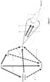
- Ground reflection is the amount of light reflected by the Earth's surface towards the aircraft. This represents the amount of direct solar illumination at the ground which is dependent on the amount of solar illumination entering the atmosphere and the angle of the sun to the ground at the latitude the aircraft is to operate at [ Figure 1 reference a].
- This value is added to the amount of illumination received at the ground from sky radiance.
- Sky radiance is indirect solar radiation that has been reflected by atmospheric particles [ Figure 1 reference b] and cloud cover [ Figure 1 reference c] (if any).
- the resulting value represents the amount of solar power received at the ground.
- the sky radiance is expected for the atmospheric conditions adjusted for the operational altitude, and is essentially the light obscured by the aircraft.
- the ground reflectance is direct solar radiation incident on the ground at the sun's angle for the latitude plus the indirect sky radiance and the reflectiveness of the terrain.
- the amount of light the aircraft must actively emit to match its background is derived in the third step.
- the blocked radiance from step two must be adjusted to take account of the portion of the ground radiance that is reflected by the aircraft found in step one.
- the net obscured light value is the amount of light that must be emitted by the aircraft.
- the final step in the method is to adjust the value from step three to take account the viewpoint of the individual under surveillance [ Figure 1 reference g]. This is the product of:
- a light source capable of producing the required level of luminescence is attached to the internal surface of the wings.
- the light source consists of (in other words, comprises) one or more light emitters such as light emitting diodes (LED).
- LED light emitting diodes
- Multiple sets of wings can be preconfigured with different types of light emitter capable of emitting different levels of illumination and having different levels of reflectivity.
- the wings may also have transparent upper and lower surfaces that allow most of the sky radiance normally obscured by the wings to be seen.
- a wing might be used if the aircraft is expected to operate in dark overcast conditions and reduces the amount of active illumination required which in turn increases the power available to maintain flight altitude for a longer duration.
- a surveillance camera is attached to the lower surface of the fuselage and light sensor to the upper surface of the fuselage.
- the sensor and camera are aligned with each other but point in opposite directions.
- a linkage between the camera and sensor allows the sensor to be automatically orientated to an angle that is 180° from that of the camera's field of vision.
- Figure 3 shows an example of the orientation and relationship of the camera and upper light sensor.
- the sensor and camera must both be capable of rotating horizontally through 360° angle and tilt vertically through 180°.
- the linkage may be implemented by a mechanical coupling or digitally through an electronic controller.
- the linkage between the camera and the upper sensor ensures that the sensor measures the background illumination from the viewpoint of the individual under surveillance.
- the upper sensor also provides the angle of observation by an individual if they were looking directly at the aircraft.
- a second light sensor is attached under the aircraft to measure ground reflectance. This sensor is static and points downward towards the ground.
- the upper and lower light sensors measure the amount of visual light incident on the aircraft's surfaces.
- the upper sensor measures the background light and the lower sensor the ground reflectance. These measurements are passed to a controller which calculates the amount of light that should be emitted by the light source.
- the controller uses the method, which is not part of the appended claims, described previously with the measurements obtained from the two light sensors, the UAV's altitude, the distance to the individual on the ground, the actual reflectance and transparency values for the aircraft instead of the nominal values.
- the controller adjusts the amount of power to the light source in real-time according to the outcome of the calculations. This active illumination brightens or dims the light source to match the background sky as seen by the individual on the ground as the UAV flies across it.
- the combination of the passive illumination through the design of the structure, configuration for an operation and the active illumination during an operation allows the aircraft to be optimally visually camouflaged for its expected operational environment.
- the amount of additional equipment for visual camouflage is reduced to two light sensors, a controller and the light sources. This represents a saving in weight over existing solutions in the prior art.
- components are chosen to be low power there is a minimal increase in the power consumption of the system which means that the UAV can extend the duration of an operation.
- the UAV is designed to be very efficient by reducing its weight and power usage thereby enabling longer flight duration than would normally be possible for small size UAV. It can therefore be launched and recovered from a location that is remote from the target to be observed which reduces the probability that the surveillance operation will be detected by the target.
- the invention includes a mode of operation of the UAV which is designed to further reduce the visual and auditory signatures of the aircraft to avoid detection.
- the UAV is launched away from the location of the individual to be observed, flown to the operating altitude and then flow to the target location.
- the UAV is flown at a constant low airspeed without undertaking any sudden movements that would increase the engine noise making it noticeable by changing the volume or pitch. Specular reflection from the airframe is also reduced by ensuring that a constant altitude is maintained with minimal changes of direction with respect to the sun, aircraft and individual under surveillance.
- the camera is used to manually locate the individual under surveillance.
- the camera can then either be manually or automatically controlled to continuously track the individual.
- the linkage between the camera and the sensor ensures that all background illumination measurements are taken in the same alignment as that of the individual if they were looking directly at the aircraft.
- the lower light sensor continuously measures the ground reflectance incident on the underside of the UAV.
- the light sources are actively controlled in real-time with the method described above with the measurements made by the sensors and camera.
- the luminescence value calculated by the controller is used to adjust the active illumination by increasing or decreasing the output from the light sources.
- the UAV may also be flow in the lowest layer of the cloud base to further obscure its visual signature.
- the novelty of the invention resides in utilising the optics properties of the terrain & atmospheric conditions, exploiting the limits of human visual acuity and restricting the viewpoint to that of the observer to reduce the equipment and complexity in implementing visual and audible camouflage for a light weight UAV. This informs the structural design, secondary configuration and operation of the UAV without adding excess weight or increasing the power requirements thereby extending the flight duration.
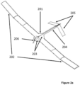
- the first embodiment shown in Figure 2a and 2b is a UAV comprising of a body 201, removable wings 202, a tail boom 204 and twin tail fins 205.
- the body 201 is designed to have a flattened cross section comprising of several trapezoid surfaces 203.
- the cross section of the tail boom 204 is diamond shaped with two tail fin surfaces 205 angled downwards from the lower side.
- the surfaces' angles are designed to reduce specular reflection to a minimum when viewed side on at an angle of 45° at an altitude of 1000m and a distance of 1000m. In sunlight this ensures that glint from the edges is reduced.
- a propeller and electric motor 206 are fitted to the body. These are chosen to be efficient and quiet in operation to reduce the auditory signature of the UAV. All upper surfaces of the fuselage are painted a matte grey and the propeller has a lighter matt grey coating.
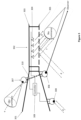
- Figure 3 shows a cross section of one of the removable wings 302 attached to either side of the body 301.
- the wings are constructed with an upper 303 and lower 305 surface between which are a number of LEDs 304.
- the body 301 also hosts the equipment that controls the active camouflage aspects of the invention during flight.
- the position and orientation of the camera 306 and background illuminance sensor 307 are shown in Figure 3 .
- Both upper sensor and the camera are attached to gimbals that allow them to rotate and tilt. These are linked 310 together so that a movement in the camera gimbal results in an equal but opposite movement in the sensor gimbal.
- the ground reflection sensor 308 is also attached to the body 301 in a position that does not obscure the field of view of the camera 306. It is angled downward towards the ground.
- the background illuminance sensor 307 and ground reflection sensor 308 are connected to microcontroller 309 which adjusts the power input to the LEDs 304 using the illuminance values measured by the sensors 307 & 308.
- the microcontroller implements the method described in the invention for active illumination to reduce the visual signature of the UAV in flight.
- Figure 3 references d, e, f, g show the path and direction of light illuminating and reflected by the UAV, previously described in relation to Figure 1 .
- Figure 4 shows a cross section of the wing of the first embodiment comprising of an upper surface 401, a rib 402 and a lower surface 403.
- the UAV in this embodiment is intended to operate over highly reflective light-coloured terrain against a background of bright clouds.
- the upper surface 401 has a uniform matt grey covering and the lower surface 403 has a uniform translucent white surface.
- the inside of the upper surface is lined with a reflective layer 405 to which a strip of LED lights 404 are attached.
- the lower power, wide beam LEDs 404 are orientated downwards.
- the lower surface is made of two parts an outer translucent skin 403 and an inner mesh lining 406. The combination of the two parts diffuses the light from the LED so that they do not appear as point light sources but as a luminescent glow.
- the second wing example is a configuration of wing structure intended for use in dark overcast conditions.
- Both the upper 501 and lower 503 surfaces are made of a transparent, non-reflective material. This allows most of the sky luminescence to be seen through the UAV wing.
- the ribs 502 and spars are the only solid components that require visually camouflaged.
- the wing material changes the amount of blocked light used in step 2 of the method to compute the active illumination required. In this embodiment fewer light sources 504 are needed and they are attached vertically to each rib to disguise the solid structures within the wing. In all other respects the UAV is the same as that in the first embodiment.
- the aircraft comprises wings that are not removable but perform the same function as the removable wings 302 described above.
Landscapes
- Engineering & Computer Science (AREA)
- Aviation & Aerospace Engineering (AREA)
- Remote Sensing (AREA)
- Radar, Positioning & Navigation (AREA)
- Mechanical Engineering (AREA)
- Chemical & Material Sciences (AREA)
- Combustion & Propulsion (AREA)
- Physics & Mathematics (AREA)
- General Physics & Mathematics (AREA)
- Automation & Control Theory (AREA)
- General Engineering & Computer Science (AREA)
- Investigating Or Analysing Materials By Optical Means (AREA)
- Circuit Arrangement For Electric Light Sources In General (AREA)
Claims (14)
- Unbemanntes Luftfahrzeug [UAV], das angepasst ist, um eine visuelle und akustische Entdeckung während eines Flugs zu minimieren, das besteht aus:einem abgeflachten, winkelförmigen Körper (201, 301);einem winkelförmigen Leitwerksträger (204) und einem Heck (205);einem oder mehreren Motoren (206) zum Antreiben eines oder mehrerer Propeller;einem oder mehreren Flügeln (302);einem oder mehreren Lichtsensoren (307, 308), die in der Lage sind, die Menge an sichtbarem Licht zu messen, das auf die UAV-Oberfläche einfällt;einer Kamera (306); undeiner Steuerung (309),wobei der eine oder die mehreren Flügel eine diffuse dunkelfarbige obere Oberfläche (303, 401) umfassen, mit einer inneren Oberfläche der oberen Oberfläche umfassend eine hochreflektierende Verkleidung, einer oder mehreren Lichtquellen (304, 404), die an der reflektierenden Verkleidung an der oberen Oberfläche nach unten zeigend horizontal angebracht sind, einer durchscheinenden unteren Oberfläche (403) und einem diffusen durchscheinenden Netz (406), das an der inneren Oberfläche der unteren Oberfläche angebracht ist.
- UAV nach Anspruch 1, wobei die Oberfläche des Körpers aus einer Anzahl von abgewinkelten trapezförmigen Abschnitten (203) besteht, die so verbunden sind, dass keine Oberfläche gekrümmt oder rechtwinklig zu einer angrenzenden Oberfläche ist.
- UAV nach Anspruch 2, wobei die Oberflächen des Körpers relativ zueinander ausgerichtet sind, um eine spiegelnde Reflexion zu minimieren.
- UAV nach Anspruch 2, wobei die Oberflächen des Körpers relativ zueinander ausgerichtet sind, um die spiegelnde Reflexion von einem Blickpunkt eines Beobachters zu minimieren, der das UAV in einem Winkel von 45° seitlich des Körpers von einer Reichweite von 1000 m erblickt, wobei der Körper in einer Höhe von 1000 m ist.
- UAV nach Anspruch 1, wobei die obere Oberfläche des Körpers, der Leitwerksträger und das Heck Licht diffus reflektieren.
- UAV nach Anspruch 1, wobei die untere Oberfläche des Körpers, der Leitwerksträger und das Heck Licht reflektieren.
- Vorrichtung nach Anspruch 1, wobei die Lichtquellen Breitstrahl-LEDs sind.
- UAV nach Anspruch 1, wobei der eine oder die mehreren Lichtsensoren einen unteren Lichtsensor (308) umfassen, der an der unteren Oberfläche des Körpers in einer festen Position nach unten zeigend angebracht ist.
- UAV nach einem der vorstehenden Ansprüche, wobei der eine oder die mehreren Lichtsensoren einen oberen Lichtsensor (307) umfassen, der an der oberen Oberfläche des Körpers angebracht ist, der in der Lage ist, sich um 360° horizontal zu drehen und um 180° vertikal zu neigen.
- UAV nach Anspruch 9, wobei die Bewegung des oberen Lichtsensors durch einen Kardanrahmen vorgenommen wird.
- UAV nach Anspruch 9, wobei die Kamera und der obere Lichtsensor verknüpft sind (310), um die Ausrichtung des oberen Lichtsensors beizubehalten, sodass er um 180° zu der Mitte des Blickfelds der Kamera in die entgegengesetzte Richtung zeigt.
- UAV nach Anspruch 11, wobei die Kamera und der obere Lichtsensor durch einen mechanischen Mechanismus (310) verknüpft sind, um die Ausrichtung beizubehalten.
- UAV nach einem der Ansprüche 9 bis 12, wenn abhängig von Anspruch 8, wobei die Steuerung mit dem oberen Lichtsensor, dem unteren Lichtsensor und den Lichtquellen verbunden ist, wobei die Steuerung Messungen der Menge an Licht, das auf eine Oberfläche einfällt, von dem oberen und dem unteren Lichtsensor, den Winkel des oberen Sensors empfängt, die Menge an zu emittierendem Licht berechnet und sie verwendet, um die Leistung zu den Lichtquellen zu steuern.
- UAV nach Anspruch 13, wobei die Steuerung konfiguriert ist, um die Leistungsmenge, die erforderlich ist, um das Luftfahrzeug aktiv zu beleuchten, zu berechnen durch:Berechnen der Menge an Licht, das durch das Luftfahrzeug reflektiert wird, aus der Bodenreflexion, die durch den unteren Lichtsensor gemessen wird;Abziehen der Menge an reflektiertem Licht von der Menge an Hintergrundlicht, das durch das Luftfahrzeug verdeckt wird, die durch den oberen Lichtsensor gemessen wird, was das verdeckte Nettolicht ergibt;Multiplizieren des verdeckten Nettolichts mit dem Oberflächeninhalt der Unterseite des Luftfahrzeugs, dem Blickwinkel des oberen Lichtsensors, der der Blickwinkel des Luftfahrzeugs durch das Individuum ist, und dem Raumwinkel des emittierten Lichts in der Richtung des Individuums, um das emittierte Licht zu ergeben;wo der Raumwinkel, der durch das Luftfahrzeug abgeschnitten wird, den Raumwinkel überschreitet, der durch das menschliche Auge auflösbar ist, Multiplizieren des Werts des emittierten Lichts mit dem Raumwinkel, der durch das Luftfahrzeug abgeschnitten wird, geteilt durch den Raumwinkel, der durch das menschliche Auge auflösbar ist; undUmwandeln des Ergebnisses der Berechnung in einen Leistungswert und Einstellen der Leistungseingabe in die Lichtquellen auf diesen Wert.
Applications Claiming Priority (2)
| Application Number | Priority Date | Filing Date | Title |
|---|---|---|---|
| GBGB1816734.6A GB201816734D0 (en) | 2018-10-15 | 2018-10-15 | Reduction of the visual and audible signatures of the UAV to minimise detection during long duration surveillance operations |
| PCT/GB2019/052836 WO2020079398A1 (en) | 2018-10-15 | 2019-10-08 | Reduction of the visual & audible signatures of the uav to minimise detection during long duration surveillance operations |
Publications (2)
| Publication Number | Publication Date |
|---|---|
| EP3867149A1 EP3867149A1 (de) | 2021-08-25 |
| EP3867149B1 true EP3867149B1 (de) | 2024-05-22 |
Family
ID=64397445
Family Applications (1)
| Application Number | Title | Priority Date | Filing Date |
|---|---|---|---|
| EP19790706.6A Active EP3867149B1 (de) | 2018-10-15 | 2019-10-08 | Reduktion der visuellen und hörbaren signaturen von uav, um die detektion während langer überwachungsoperationen zu minimieren |
Country Status (5)
| Country | Link |
|---|---|
| US (1) | US11192647B2 (de) |
| EP (1) | EP3867149B1 (de) |
| AU (1) | AU2019362643A1 (de) |
| GB (2) | GB201816734D0 (de) |
| WO (2) | WO2020079398A1 (de) |
Families Citing this family (2)
| Publication number | Priority date | Publication date | Assignee | Title |
|---|---|---|---|---|
| GB2566023B (en) * | 2017-08-30 | 2020-06-17 | Jaguar Land Rover Ltd | Controller for an unmanned aerial vehicle |
| US12145727B2 (en) | 2022-08-19 | 2024-11-19 | University Of Kansas | Enhanced observability uninhabited aerial vehicles and methods of use |
Citations (3)
| Publication number | Priority date | Publication date | Assignee | Title |
|---|---|---|---|---|
| US4489329A (en) * | 1981-11-26 | 1984-12-18 | Societe Nationale Industrielle Et Aerospatiale | Sensor release latch for space vehicle |
| US20110095692A1 (en) * | 2008-05-16 | 2011-04-28 | Bae Systems Plc | Camouflage panel |
| CN105984578A (zh) * | 2016-05-12 | 2016-10-05 | 中国航空工业集团公司西安飞机设计研究所 | 飞机及将有机电致发光板敷设在飞机外表面上的方法 |
Family Cites Families (17)
| Publication number | Priority date | Publication date | Assignee | Title |
|---|---|---|---|---|
| US5250950A (en) * | 1979-02-13 | 1993-10-05 | Lockheed Corporation | Vehicle |
| GB9915977D0 (en) * | 1999-07-08 | 1999-09-15 | British Aerospace | Aircraft noise reduction apparatus |
| SE522154C2 (sv) * | 2002-05-15 | 2004-01-20 | Saab Ab | Stealth-farkost |
| US6749153B1 (en) * | 2002-12-04 | 2004-06-15 | The Boeing Company | Survivable and reusable launch vehicle |
| US7059931B2 (en) | 2003-05-27 | 2006-06-13 | Veratech Aero-Rpv Corporation | Reduced visibility rotorcraft and method of controlling flight of reduced visibility rotorcraft |
| US20050040283A1 (en) * | 2003-08-18 | 2005-02-24 | Richard Tyler Frazer | Method of propulsion and attitude control in fluid environments and vehicles utilizing said method |
| US7999720B2 (en) * | 2006-02-13 | 2011-08-16 | The Invention Science Fund I, Llc | Camouflage positional elements |
| US8157205B2 (en) * | 2006-03-04 | 2012-04-17 | Mcwhirk Bruce Kimberly | Multibody aircrane |
| WO2010002379A1 (en) * | 2008-06-30 | 2010-01-07 | Alves James F | Digital camera control system |
| KR101229944B1 (ko) * | 2009-10-28 | 2013-02-15 | 한국과학기술원 | 가상 투명 비행체 |
| WO2013070296A2 (en) * | 2011-08-19 | 2013-05-16 | Aerovironment, Inc. | Aircraft system for reduced observer visibility |
| DE102013103369B4 (de) * | 2013-04-04 | 2017-05-04 | Airbus Operations Gmbh | Außenstrukturbauteil für ein Flugzeug, Flugzeug mit einem Außenstrukturbauteil und Verfahren zum Herstellen eines Außenstrukturbauteils für ein Flugzeug |
| GR20130100619A (el) * | 2013-10-25 | 2015-05-18 | Ιωαννης Γεωργιου Μικρος | Μικρη πτηνομορφη πτητικη συσκευη και εφαρμογες |
| CN109690433B (zh) * | 2016-09-13 | 2022-05-17 | 杭州零零科技有限公司 | 具有环境感知的无人驾驶空中车辆系统和方法 |
| US10571225B2 (en) * | 2016-11-22 | 2020-02-25 | Walmart Apollo, Llc | System and method for camouflaging and recharging autonomous vehicles |
| US10095242B1 (en) * | 2017-07-05 | 2018-10-09 | Qualcomm Incorporated | Invertible drone for selective power capture |
| US10870486B2 (en) * | 2017-09-22 | 2020-12-22 | Stephen Lee Bailey | Diamond quadcopter |
-
2018
- 2018-10-15 GB GBGB1816734.6A patent/GB201816734D0/en not_active Ceased
-
2019
- 2019-10-08 EP EP19790706.6A patent/EP3867149B1/de active Active
- 2019-10-08 AU AU2019362643A patent/AU2019362643A1/en not_active Abandoned
- 2019-10-08 WO PCT/GB2019/052836 patent/WO2020079398A1/en not_active Ceased
- 2019-10-08 US US17/284,685 patent/US11192647B2/en not_active Expired - Fee Related
- 2019-10-09 GB GB1914579.6A patent/GB2579885B/en not_active Expired - Fee Related
- 2019-10-09 WO PCT/GB2019/052861 patent/WO2020079399A1/en not_active Ceased
Patent Citations (3)
| Publication number | Priority date | Publication date | Assignee | Title |
|---|---|---|---|---|
| US4489329A (en) * | 1981-11-26 | 1984-12-18 | Societe Nationale Industrielle Et Aerospatiale | Sensor release latch for space vehicle |
| US20110095692A1 (en) * | 2008-05-16 | 2011-04-28 | Bae Systems Plc | Camouflage panel |
| CN105984578A (zh) * | 2016-05-12 | 2016-10-05 | 中国航空工业集团公司西安飞机设计研究所 | 飞机及将有机电致发光板敷设在飞机外表面上的方法 |
Also Published As
| Publication number | Publication date |
|---|---|
| GB2579885B (en) | 2022-09-14 |
| AU2019362643A1 (en) | 2021-05-13 |
| WO2020079399A1 (en) | 2020-04-23 |
| GB201816734D0 (en) | 2018-11-28 |
| US11192647B2 (en) | 2021-12-07 |
| EP3867149A1 (de) | 2021-08-25 |
| WO2020079398A1 (en) | 2020-04-23 |
| GB201914579D0 (en) | 2019-11-20 |
| GB2579885A (en) | 2020-07-08 |
| US20210309362A1 (en) | 2021-10-07 |
Similar Documents
| Publication | Publication Date | Title |
|---|---|---|
| CN106167101B (zh) | 飞机着陆灯单元、飞机外部照明系统以及操作飞机着陆灯单元的方法 | |
| US10773825B1 (en) | Laser lighting system for use in landing an aircraft in a degraded visual environment | |
| US7999720B2 (en) | Camouflage positional elements | |
| CA2909314C (fr) | Procede et systeme de visualisation de l'environnement externe d'un avion, ainsi que porte d'avion equipee d'un tel systeme | |
| US9745961B2 (en) | Offshore wind farm illumination | |
| US8297776B2 (en) | “Lip light” automatically controlled by the position of the head | |
| EP3867149B1 (de) | Reduktion der visuellen und hörbaren signaturen von uav, um die detektion während langer überwachungsoperationen zu minimieren | |
| US10351258B1 (en) | System for protecting aircraft against bird strikes | |
| CN107757936A (zh) | 外部飞机灯单元和警示地面人员的方法 | |
| JP2021042957A (ja) | 航空機を使用してレーダを反射させるためのシステム及び方法 | |
| EP3269596B1 (de) | Hubschraubersuchscheinwerfer | |
| EP4331981A1 (de) | Drehflügelflugzeug mit einem blattspitzenbeleuchtungssystem | |
| EP3851384B1 (de) | Flugzeug mit einem beleuchtungssystem für laufschaufeln | |
| KR101229944B1 (ko) | 가상 투명 비행체 | |
| RU2671926C1 (ru) | Система огней глиссады, обеспечивающая визуальную и оптическую посадку в очках ночного видения вертолета на корабль в темное время суток | |
| EP4115257B1 (de) | Abfangen von drohnen | |
| US9868546B2 (en) | Dual-mode vehicle light system | |
| EP4331978B1 (de) | Drehflügelflugzeug mit einem blattspitzenbeleuchtungssystem | |
| Macheret et al. | Conceptual Design of Low-Signature High-Endurance Hybrid-Electric UAV | |
| RU2847122C1 (ru) | БПЛА с адаптивной цифровой системой оптической невидимости | |
| US11724821B2 (en) | Helicopter search light and method of operating a helicopter search light | |
| Jennings et al. | Preliminary assessment of night vision goggles in airborne forest fire suppression | |
| EP3876071A1 (de) | Abfangen von drohnen | |
| CN118965553A (zh) | 反舰载固定翼预警机飞行器的设计方法及飞行器 | |
| Nambiar | Modern camouflage techniques |
Legal Events
| Date | Code | Title | Description |
|---|---|---|---|
| STAA | Information on the status of an ep patent application or granted ep patent |
Free format text: STATUS: UNKNOWN |
|
| STAA | Information on the status of an ep patent application or granted ep patent |
Free format text: STATUS: THE INTERNATIONAL PUBLICATION HAS BEEN MADE |
|
| PUAI | Public reference made under article 153(3) epc to a published international application that has entered the european phase |
Free format text: ORIGINAL CODE: 0009012 |
|
| STAA | Information on the status of an ep patent application or granted ep patent |
Free format text: STATUS: REQUEST FOR EXAMINATION WAS MADE |
|
| 17P | Request for examination filed |
Effective date: 20210420 |
|
| AK | Designated contracting states |
Kind code of ref document: A1 Designated state(s): AL AT BE BG CH CY CZ DE DK EE ES FI FR GB GR HR HU IE IS IT LI LT LU LV MC MK MT NL NO PL PT RO RS SE SI SK SM TR |
|
| DAV | Request for validation of the european patent (deleted) | ||
| DAX | Request for extension of the european patent (deleted) | ||
| STAA | Information on the status of an ep patent application or granted ep patent |
Free format text: STATUS: EXAMINATION IS IN PROGRESS |
|
| 17Q | First examination report despatched |
Effective date: 20221124 |
|
| REG | Reference to a national code |
Ref country code: DE Ipc: B64U0020100000 Ref legal event code: R079 Ref document number: 602019052643 Country of ref document: DE Free format text: PREVIOUS MAIN CLASS: B64C0039020000 |
|
| RIC1 | Information provided on ipc code assigned before grant |
Ipc: B64U 20/20 20230101ALN20231023BHEP Ipc: B64C 39/02 20060101ALI20231023BHEP Ipc: B64U 50/19 20230101ALI20231023BHEP Ipc: B64U 10/25 20230101ALI20231023BHEP Ipc: B64U 20/10 20230101AFI20231023BHEP |
|
| GRAP | Despatch of communication of intention to grant a patent |
Free format text: ORIGINAL CODE: EPIDOSNIGR1 |
|
| STAA | Information on the status of an ep patent application or granted ep patent |
Free format text: STATUS: GRANT OF PATENT IS INTENDED |
|
| RIC1 | Information provided on ipc code assigned before grant |
Ipc: B64U 20/20 20230101ALN20231106BHEP Ipc: B64C 39/02 20060101ALI20231106BHEP Ipc: B64U 50/19 20230101ALI20231106BHEP Ipc: B64U 10/25 20230101ALI20231106BHEP Ipc: B64U 20/10 20230101AFI20231106BHEP |
|
| RIC1 | Information provided on ipc code assigned before grant |
Ipc: B64U 20/20 20230101ALN20231115BHEP Ipc: B64C 39/02 20060101ALI20231115BHEP Ipc: B64U 50/19 20230101ALI20231115BHEP Ipc: B64U 10/25 20230101ALI20231115BHEP Ipc: B64U 20/10 20230101AFI20231115BHEP |
|
| INTG | Intention to grant announced |
Effective date: 20231213 |
|
| GRAS | Grant fee paid |
Free format text: ORIGINAL CODE: EPIDOSNIGR3 |
|
| GRAA | (expected) grant |
Free format text: ORIGINAL CODE: 0009210 |
|
| STAA | Information on the status of an ep patent application or granted ep patent |
Free format text: STATUS: THE PATENT HAS BEEN GRANTED |
|
| AK | Designated contracting states |
Kind code of ref document: B1 Designated state(s): AL AT BE BG CH CY CZ DE DK EE ES FI FR GB GR HR HU IE IS IT LI LT LU LV MC MK MT NL NO PL PT RO RS SE SI SK SM TR |
|
| REG | Reference to a national code |
Ref country code: GB Ref legal event code: FG4D |
|
| REG | Reference to a national code |
Ref country code: CH Ref legal event code: EP |
|
| REG | Reference to a national code |
Ref country code: DE Ref legal event code: R096 Ref document number: 602019052643 Country of ref document: DE |
|
| REG | Reference to a national code |
Ref country code: IE Ref legal event code: FG4D |
|
| REG | Reference to a national code |
Ref country code: LT Ref legal event code: MG9D |
|
| REG | Reference to a national code |
Ref country code: NL Ref legal event code: MP Effective date: 20240522 |
|
| PG25 | Lapsed in a contracting state [announced via postgrant information from national office to epo] |
Ref country code: IS Free format text: LAPSE BECAUSE OF FAILURE TO SUBMIT A TRANSLATION OF THE DESCRIPTION OR TO PAY THE FEE WITHIN THE PRESCRIBED TIME-LIMIT Effective date: 20240922 |
|
| PG25 | Lapsed in a contracting state [announced via postgrant information from national office to epo] |
Ref country code: BG Free format text: LAPSE BECAUSE OF FAILURE TO SUBMIT A TRANSLATION OF THE DESCRIPTION OR TO PAY THE FEE WITHIN THE PRESCRIBED TIME-LIMIT Effective date: 20240522 |
|
| PG25 | Lapsed in a contracting state [announced via postgrant information from national office to epo] |
Ref country code: HR Free format text: LAPSE BECAUSE OF FAILURE TO SUBMIT A TRANSLATION OF THE DESCRIPTION OR TO PAY THE FEE WITHIN THE PRESCRIBED TIME-LIMIT Effective date: 20240522 Ref country code: FI Free format text: LAPSE BECAUSE OF FAILURE TO SUBMIT A TRANSLATION OF THE DESCRIPTION OR TO PAY THE FEE WITHIN THE PRESCRIBED TIME-LIMIT Effective date: 20240522 |
|
| PG25 | Lapsed in a contracting state [announced via postgrant information from national office to epo] |
Ref country code: GR Free format text: LAPSE BECAUSE OF FAILURE TO SUBMIT A TRANSLATION OF THE DESCRIPTION OR TO PAY THE FEE WITHIN THE PRESCRIBED TIME-LIMIT Effective date: 20240823 |
|
| PG25 | Lapsed in a contracting state [announced via postgrant information from national office to epo] |
Ref country code: PT Free format text: LAPSE BECAUSE OF FAILURE TO SUBMIT A TRANSLATION OF THE DESCRIPTION OR TO PAY THE FEE WITHIN THE PRESCRIBED TIME-LIMIT Effective date: 20240923 |
|
| REG | Reference to a national code |
Ref country code: AT Ref legal event code: MK05 Ref document number: 1688595 Country of ref document: AT Kind code of ref document: T Effective date: 20240522 |
|
| PG25 | Lapsed in a contracting state [announced via postgrant information from national office to epo] |
Ref country code: NL Free format text: LAPSE BECAUSE OF FAILURE TO SUBMIT A TRANSLATION OF THE DESCRIPTION OR TO PAY THE FEE WITHIN THE PRESCRIBED TIME-LIMIT Effective date: 20240522 |
|
| PG25 | Lapsed in a contracting state [announced via postgrant information from national office to epo] |
Ref country code: ES Free format text: LAPSE BECAUSE OF FAILURE TO SUBMIT A TRANSLATION OF THE DESCRIPTION OR TO PAY THE FEE WITHIN THE PRESCRIBED TIME-LIMIT Effective date: 20240522 |
|
| PG25 | Lapsed in a contracting state [announced via postgrant information from national office to epo] |
Ref country code: AT Free format text: LAPSE BECAUSE OF FAILURE TO SUBMIT A TRANSLATION OF THE DESCRIPTION OR TO PAY THE FEE WITHIN THE PRESCRIBED TIME-LIMIT Effective date: 20240522 |
|
| PG25 | Lapsed in a contracting state [announced via postgrant information from national office to epo] |
Ref country code: PL Free format text: LAPSE BECAUSE OF FAILURE TO SUBMIT A TRANSLATION OF THE DESCRIPTION OR TO PAY THE FEE WITHIN THE PRESCRIBED TIME-LIMIT Effective date: 20240522 |
|
| PG25 | Lapsed in a contracting state [announced via postgrant information from national office to epo] |
Ref country code: LV Free format text: LAPSE BECAUSE OF FAILURE TO SUBMIT A TRANSLATION OF THE DESCRIPTION OR TO PAY THE FEE WITHIN THE PRESCRIBED TIME-LIMIT Effective date: 20240522 |
|
| PG25 | Lapsed in a contracting state [announced via postgrant information from national office to epo] |
Ref country code: PT Free format text: LAPSE BECAUSE OF FAILURE TO SUBMIT A TRANSLATION OF THE DESCRIPTION OR TO PAY THE FEE WITHIN THE PRESCRIBED TIME-LIMIT Effective date: 20240923 Ref country code: PL Free format text: LAPSE BECAUSE OF FAILURE TO SUBMIT A TRANSLATION OF THE DESCRIPTION OR TO PAY THE FEE WITHIN THE PRESCRIBED TIME-LIMIT Effective date: 20240522 Ref country code: NO Free format text: LAPSE BECAUSE OF FAILURE TO SUBMIT A TRANSLATION OF THE DESCRIPTION OR TO PAY THE FEE WITHIN THE PRESCRIBED TIME-LIMIT Effective date: 20240822 Ref country code: NL Free format text: LAPSE BECAUSE OF FAILURE TO SUBMIT A TRANSLATION OF THE DESCRIPTION OR TO PAY THE FEE WITHIN THE PRESCRIBED TIME-LIMIT Effective date: 20240522 Ref country code: LV Free format text: LAPSE BECAUSE OF FAILURE TO SUBMIT A TRANSLATION OF THE DESCRIPTION OR TO PAY THE FEE WITHIN THE PRESCRIBED TIME-LIMIT Effective date: 20240522 Ref country code: IS Free format text: LAPSE BECAUSE OF FAILURE TO SUBMIT A TRANSLATION OF THE DESCRIPTION OR TO PAY THE FEE WITHIN THE PRESCRIBED TIME-LIMIT Effective date: 20240922 Ref country code: HR Free format text: LAPSE BECAUSE OF FAILURE TO SUBMIT A TRANSLATION OF THE DESCRIPTION OR TO PAY THE FEE WITHIN THE PRESCRIBED TIME-LIMIT Effective date: 20240522 Ref country code: GR Free format text: LAPSE BECAUSE OF FAILURE TO SUBMIT A TRANSLATION OF THE DESCRIPTION OR TO PAY THE FEE WITHIN THE PRESCRIBED TIME-LIMIT Effective date: 20240823 Ref country code: FI Free format text: LAPSE BECAUSE OF FAILURE TO SUBMIT A TRANSLATION OF THE DESCRIPTION OR TO PAY THE FEE WITHIN THE PRESCRIBED TIME-LIMIT Effective date: 20240522 Ref country code: ES Free format text: LAPSE BECAUSE OF FAILURE TO SUBMIT A TRANSLATION OF THE DESCRIPTION OR TO PAY THE FEE WITHIN THE PRESCRIBED TIME-LIMIT Effective date: 20240522 Ref country code: BG Free format text: LAPSE BECAUSE OF FAILURE TO SUBMIT A TRANSLATION OF THE DESCRIPTION OR TO PAY THE FEE WITHIN THE PRESCRIBED TIME-LIMIT Effective date: 20240522 Ref country code: AT Free format text: LAPSE BECAUSE OF FAILURE TO SUBMIT A TRANSLATION OF THE DESCRIPTION OR TO PAY THE FEE WITHIN THE PRESCRIBED TIME-LIMIT Effective date: 20240522 Ref country code: RS Free format text: LAPSE BECAUSE OF FAILURE TO SUBMIT A TRANSLATION OF THE DESCRIPTION OR TO PAY THE FEE WITHIN THE PRESCRIBED TIME-LIMIT Effective date: 20240822 |
|
| PG25 | Lapsed in a contracting state [announced via postgrant information from national office to epo] |
Ref country code: DK Free format text: LAPSE BECAUSE OF FAILURE TO SUBMIT A TRANSLATION OF THE DESCRIPTION OR TO PAY THE FEE WITHIN THE PRESCRIBED TIME-LIMIT Effective date: 20240522 |
|
| PG25 | Lapsed in a contracting state [announced via postgrant information from national office to epo] |
Ref country code: EE Free format text: LAPSE BECAUSE OF FAILURE TO SUBMIT A TRANSLATION OF THE DESCRIPTION OR TO PAY THE FEE WITHIN THE PRESCRIBED TIME-LIMIT Effective date: 20240522 |
|
| PG25 | Lapsed in a contracting state [announced via postgrant information from national office to epo] |
Ref country code: CZ Free format text: LAPSE BECAUSE OF FAILURE TO SUBMIT A TRANSLATION OF THE DESCRIPTION OR TO PAY THE FEE WITHIN THE PRESCRIBED TIME-LIMIT Effective date: 20240522 |
|
| PG25 | Lapsed in a contracting state [announced via postgrant information from national office to epo] |
Ref country code: SK Free format text: LAPSE BECAUSE OF FAILURE TO SUBMIT A TRANSLATION OF THE DESCRIPTION OR TO PAY THE FEE WITHIN THE PRESCRIBED TIME-LIMIT Effective date: 20240522 Ref country code: RO Free format text: LAPSE BECAUSE OF FAILURE TO SUBMIT A TRANSLATION OF THE DESCRIPTION OR TO PAY THE FEE WITHIN THE PRESCRIBED TIME-LIMIT Effective date: 20240522 |
|
| PG25 | Lapsed in a contracting state [announced via postgrant information from national office to epo] |
Ref country code: SM Free format text: LAPSE BECAUSE OF FAILURE TO SUBMIT A TRANSLATION OF THE DESCRIPTION OR TO PAY THE FEE WITHIN THE PRESCRIBED TIME-LIMIT Effective date: 20240522 |
|
| PG25 | Lapsed in a contracting state [announced via postgrant information from national office to epo] |
Ref country code: SM Free format text: LAPSE BECAUSE OF FAILURE TO SUBMIT A TRANSLATION OF THE DESCRIPTION OR TO PAY THE FEE WITHIN THE PRESCRIBED TIME-LIMIT Effective date: 20240522 Ref country code: SK Free format text: LAPSE BECAUSE OF FAILURE TO SUBMIT A TRANSLATION OF THE DESCRIPTION OR TO PAY THE FEE WITHIN THE PRESCRIBED TIME-LIMIT Effective date: 20240522 Ref country code: RO Free format text: LAPSE BECAUSE OF FAILURE TO SUBMIT A TRANSLATION OF THE DESCRIPTION OR TO PAY THE FEE WITHIN THE PRESCRIBED TIME-LIMIT Effective date: 20240522 Ref country code: EE Free format text: LAPSE BECAUSE OF FAILURE TO SUBMIT A TRANSLATION OF THE DESCRIPTION OR TO PAY THE FEE WITHIN THE PRESCRIBED TIME-LIMIT Effective date: 20240522 Ref country code: DK Free format text: LAPSE BECAUSE OF FAILURE TO SUBMIT A TRANSLATION OF THE DESCRIPTION OR TO PAY THE FEE WITHIN THE PRESCRIBED TIME-LIMIT Effective date: 20240522 Ref country code: CZ Free format text: LAPSE BECAUSE OF FAILURE TO SUBMIT A TRANSLATION OF THE DESCRIPTION OR TO PAY THE FEE WITHIN THE PRESCRIBED TIME-LIMIT Effective date: 20240522 |
|
| PG25 | Lapsed in a contracting state [announced via postgrant information from national office to epo] |
Ref country code: IT Free format text: LAPSE BECAUSE OF FAILURE TO SUBMIT A TRANSLATION OF THE DESCRIPTION OR TO PAY THE FEE WITHIN THE PRESCRIBED TIME-LIMIT Effective date: 20240522 |
|
| REG | Reference to a national code |
Ref country code: DE Ref legal event code: R097 Ref document number: 602019052643 Country of ref document: DE |
|
| PLBE | No opposition filed within time limit |
Free format text: ORIGINAL CODE: 0009261 |
|
| STAA | Information on the status of an ep patent application or granted ep patent |
Free format text: STATUS: NO OPPOSITION FILED WITHIN TIME LIMIT |
|
| PG25 | Lapsed in a contracting state [announced via postgrant information from national office to epo] |
Ref country code: SI Free format text: LAPSE BECAUSE OF FAILURE TO SUBMIT A TRANSLATION OF THE DESCRIPTION OR TO PAY THE FEE WITHIN THE PRESCRIBED TIME-LIMIT Effective date: 20240522 |
|
| 26N | No opposition filed |
Effective date: 20250225 |
|
| REG | Reference to a national code |
Ref country code: DE Ref legal event code: R119 Ref document number: 602019052643 Country of ref document: DE |
|
| REG | Reference to a national code |
Ref country code: CH Ref legal event code: PL |
|
| GBPC | Gb: european patent ceased through non-payment of renewal fee |
Effective date: 20241008 |
|
| PG25 | Lapsed in a contracting state [announced via postgrant information from national office to epo] |
Ref country code: MC Free format text: LAPSE BECAUSE OF FAILURE TO SUBMIT A TRANSLATION OF THE DESCRIPTION OR TO PAY THE FEE WITHIN THE PRESCRIBED TIME-LIMIT Effective date: 20240522 |
|
| PG25 | Lapsed in a contracting state [announced via postgrant information from national office to epo] |
Ref country code: DE Free format text: LAPSE BECAUSE OF NON-PAYMENT OF DUE FEES Effective date: 20250501 |
|
| PG25 | Lapsed in a contracting state [announced via postgrant information from national office to epo] |
Ref country code: GB Free format text: LAPSE BECAUSE OF NON-PAYMENT OF DUE FEES Effective date: 20241008 |
|
| PG25 | Lapsed in a contracting state [announced via postgrant information from national office to epo] |
Ref country code: BE Free format text: LAPSE BECAUSE OF NON-PAYMENT OF DUE FEES Effective date: 20241031 Ref country code: LU Free format text: LAPSE BECAUSE OF NON-PAYMENT OF DUE FEES Effective date: 20241008 |
|
| PG25 | Lapsed in a contracting state [announced via postgrant information from national office to epo] |
Ref country code: FR Free format text: LAPSE BECAUSE OF NON-PAYMENT OF DUE FEES Effective date: 20241031 |
|
| PG25 | Lapsed in a contracting state [announced via postgrant information from national office to epo] |
Ref country code: CH Free format text: LAPSE BECAUSE OF NON-PAYMENT OF DUE FEES Effective date: 20241031 |
|
| REG | Reference to a national code |
Ref country code: BE Ref legal event code: MM Effective date: 20241031 |
|
| PG25 | Lapsed in a contracting state [announced via postgrant information from national office to epo] |
Ref country code: SE Free format text: LAPSE BECAUSE OF FAILURE TO SUBMIT A TRANSLATION OF THE DESCRIPTION OR TO PAY THE FEE WITHIN THE PRESCRIBED TIME-LIMIT Effective date: 20240522 |
|
| PG25 | Lapsed in a contracting state [announced via postgrant information from national office to epo] |
Ref country code: IE Free format text: LAPSE BECAUSE OF NON-PAYMENT OF DUE FEES Effective date: 20241008 |
|
| PG25 | Lapsed in a contracting state [announced via postgrant information from national office to epo] |
Ref country code: CY Free format text: LAPSE BECAUSE OF FAILURE TO SUBMIT A TRANSLATION OF THE DESCRIPTION OR TO PAY THE FEE WITHIN THE PRESCRIBED TIME-LIMIT; INVALID AB INITIO Effective date: 20191008 |