EP3867124B1 - Elektromechanisches lenksystem mit einem federelement für ein untersetzungsgetriebe des lenksystems - Google Patents
Elektromechanisches lenksystem mit einem federelement für ein untersetzungsgetriebe des lenksystems Download PDFInfo
- Publication number
- EP3867124B1 EP3867124B1 EP19790184.6A EP19790184A EP3867124B1 EP 3867124 B1 EP3867124 B1 EP 3867124B1 EP 19790184 A EP19790184 A EP 19790184A EP 3867124 B1 EP3867124 B1 EP 3867124B1
- Authority
- EP
- European Patent Office
- Prior art keywords
- steering system
- electromechanical steering
- longitudinal axis
- spring
- spring arms
- Prior art date
- Legal status (The legal status is an assumption and is not a legal conclusion. Google has not performed a legal analysis and makes no representation as to the accuracy of the status listed.)
- Active
Links
Images


Classifications
-
- B—PERFORMING OPERATIONS; TRANSPORTING
- B62—LAND VEHICLES FOR TRAVELLING OTHERWISE THAN ON RAILS
- B62D—MOTOR VEHICLES; TRAILERS
- B62D5/00—Power-assisted or power-driven steering
- B62D5/04—Power-assisted or power-driven steering electrical, e.g. using an electric servo-motor connected to, or forming part of, the steering gear
- B62D5/0409—Electric motor acting on the steering column
-
- B—PERFORMING OPERATIONS; TRANSPORTING
- B62—LAND VEHICLES FOR TRAVELLING OTHERWISE THAN ON RAILS
- B62D—MOTOR VEHICLES; TRAILERS
- B62D5/00—Power-assisted or power-driven steering
- B62D5/04—Power-assisted or power-driven steering electrical, e.g. using an electric servo-motor connected to, or forming part of, the steering gear
- B62D5/0442—Conversion of rotational into longitudinal movement
- B62D5/0454—Worm gears
-
- F—MECHANICAL ENGINEERING; LIGHTING; HEATING; WEAPONS; BLASTING
- F16—ENGINEERING ELEMENTS AND UNITS; GENERAL MEASURES FOR PRODUCING AND MAINTAINING EFFECTIVE FUNCTIONING OF MACHINES OR INSTALLATIONS; THERMAL INSULATION IN GENERAL
- F16C—SHAFTS; FLEXIBLE SHAFTS; ELEMENTS OR CRANKSHAFT MECHANISMS; ROTARY BODIES OTHER THAN GEARING ELEMENTS; BEARINGS
- F16C19/00—Bearings with rolling contact, for exclusively rotary movement
- F16C19/54—Systems consisting of a plurality of bearings with rolling friction
- F16C19/546—Systems with spaced apart rolling bearings including at least one angular contact bearing
- F16C19/547—Systems with spaced apart rolling bearings including at least one angular contact bearing with two angular contact rolling bearings
- F16C19/548—Systems with spaced apart rolling bearings including at least one angular contact bearing with two angular contact rolling bearings in O-arrangement
-
- F—MECHANICAL ENGINEERING; LIGHTING; HEATING; WEAPONS; BLASTING
- F16—ENGINEERING ELEMENTS AND UNITS; GENERAL MEASURES FOR PRODUCING AND MAINTAINING EFFECTIVE FUNCTIONING OF MACHINES OR INSTALLATIONS; THERMAL INSULATION IN GENERAL
- F16C—SHAFTS; FLEXIBLE SHAFTS; ELEMENTS OR CRANKSHAFT MECHANISMS; ROTARY BODIES OTHER THAN GEARING ELEMENTS; BEARINGS
- F16C25/00—Bearings for exclusively rotary movement adjustable for wear or play
- F16C25/06—Ball or roller bearings
- F16C25/08—Ball or roller bearings self-adjusting
- F16C25/083—Ball or roller bearings self-adjusting with resilient means acting axially on a race ring to preload the bearing
-
- F—MECHANICAL ENGINEERING; LIGHTING; HEATING; WEAPONS; BLASTING
- F16—ENGINEERING ELEMENTS AND UNITS; GENERAL MEASURES FOR PRODUCING AND MAINTAINING EFFECTIVE FUNCTIONING OF MACHINES OR INSTALLATIONS; THERMAL INSULATION IN GENERAL
- F16C—SHAFTS; FLEXIBLE SHAFTS; ELEMENTS OR CRANKSHAFT MECHANISMS; ROTARY BODIES OTHER THAN GEARING ELEMENTS; BEARINGS
- F16C27/00—Elastic or yielding bearings or bearing supports, for exclusively rotary movement
- F16C27/06—Elastic or yielding bearings or bearing supports, for exclusively rotary movement by means of parts of rubber or like materials
- F16C27/066—Ball or roller bearings
-
- F—MECHANICAL ENGINEERING; LIGHTING; HEATING; WEAPONS; BLASTING
- F16—ENGINEERING ELEMENTS AND UNITS; GENERAL MEASURES FOR PRODUCING AND MAINTAINING EFFECTIVE FUNCTIONING OF MACHINES OR INSTALLATIONS; THERMAL INSULATION IN GENERAL
- F16F—SPRINGS; SHOCK-ABSORBERS; MEANS FOR DAMPING VIBRATION
- F16F1/00—Springs
- F16F1/02—Springs made of steel or other material having low internal friction; Wound, torsion, leaf, cup, ring or the like springs, the material of the spring not being relevant
- F16F1/024—Covers or coatings therefor
-
- F—MECHANICAL ENGINEERING; LIGHTING; HEATING; WEAPONS; BLASTING
- F16—ENGINEERING ELEMENTS AND UNITS; GENERAL MEASURES FOR PRODUCING AND MAINTAINING EFFECTIVE FUNCTIONING OF MACHINES OR INSTALLATIONS; THERMAL INSULATION IN GENERAL
- F16F—SPRINGS; SHOCK-ABSORBERS; MEANS FOR DAMPING VIBRATION
- F16F1/00—Springs
- F16F1/02—Springs made of steel or other material having low internal friction; Wound, torsion, leaf, cup, ring or the like springs, the material of the spring not being relevant
- F16F1/32—Belleville-type springs
- F16F1/324—Belleville-type springs characterised by having tongues or arms directed in a generally radial direction, i.e. diaphragm-type springs
-
- F—MECHANICAL ENGINEERING; LIGHTING; HEATING; WEAPONS; BLASTING
- F16—ENGINEERING ELEMENTS AND UNITS; GENERAL MEASURES FOR PRODUCING AND MAINTAINING EFFECTIVE FUNCTIONING OF MACHINES OR INSTALLATIONS; THERMAL INSULATION IN GENERAL
- F16C—SHAFTS; FLEXIBLE SHAFTS; ELEMENTS OR CRANKSHAFT MECHANISMS; ROTARY BODIES OTHER THAN GEARING ELEMENTS; BEARINGS
- F16C2326/00—Articles relating to transporting
- F16C2326/20—Land vehicles
- F16C2326/24—Steering systems, e.g. steering rods or columns
-
- F—MECHANICAL ENGINEERING; LIGHTING; HEATING; WEAPONS; BLASTING
- F16—ENGINEERING ELEMENTS AND UNITS; GENERAL MEASURES FOR PRODUCING AND MAINTAINING EFFECTIVE FUNCTIONING OF MACHINES OR INSTALLATIONS; THERMAL INSULATION IN GENERAL
- F16C—SHAFTS; FLEXIBLE SHAFTS; ELEMENTS OR CRANKSHAFT MECHANISMS; ROTARY BODIES OTHER THAN GEARING ELEMENTS; BEARINGS
- F16C2380/00—Electrical apparatus
- F16C2380/26—Dynamo-electric machines or combinations therewith, e.g. electro-motors and generators
- F16C2380/27—Motor coupled with a gear, e.g. worm gears
-
- F—MECHANICAL ENGINEERING; LIGHTING; HEATING; WEAPONS; BLASTING
- F16—ENGINEERING ELEMENTS AND UNITS; GENERAL MEASURES FOR PRODUCING AND MAINTAINING EFFECTIVE FUNCTIONING OF MACHINES OR INSTALLATIONS; THERMAL INSULATION IN GENERAL
- F16F—SPRINGS; SHOCK-ABSORBERS; MEANS FOR DAMPING VIBRATION
- F16F2234/00—Shape
- F16F2234/06—Shape plane or flat
Definitions
- the present invention relates to an electromechanical steering system having the features of the preamble of claim 1.
- an electric motor In electromechanical steering systems, an electric motor generates a torque that is transmitted to a gearbox and superimposed there on the steering torque provided by the driver.
- a generic electromechanical power steering has an electric servomotor that drives a worm shaft that meshes with a worm wheel arranged on a steering shaft, the worm wheel being in operative connection with an input shaft of a steering gear and the worm shaft and the steering shaft being rotatably mounted in a common gear housing .
- the worm shaft is connected to the motor shaft of the electric servomotor via a coupling.
- the bearing of the worm wheel is supported and prestressed in the axial and radial directions by means of a prestressing element in the form of a spring, as is known, for example, from the document JP 2001-280428 A is known.
- a prestressing element in the form of a spring as is known, for example, from the document JP 2001-280428 A is known.
- Wave springs known for use also have the disadvantage that there is no planar (symmetrical) load distribution is possible. A tilting moment is created by the end and the beginning of the winding. In the installation situation there is a risk of damage to the end shield and there is only a small amount of travel in the radial direction to achieve a large spring deflection.
- an electromechanical steering system for a motor vehicle with a reduction gear comprising a worm and a worm wheel, the worm wheel being mounted in a gear housing on a first end face in a first bearing and on a second end face in a second bearing so as to be rotatable about a longitudinal axis.
- both bearings have an outer ring and an inner ring, between which rolling elements are arranged, wherein the inner rings are arranged in a rotationally fixed manner on a shaft driven by the worm wheel and the outer rings are seated in the gear housing, and wherein in the direction of the longitudinal axis between the inner ring of the second bearing and the Worm wheel, a spring element is arranged.
- the spring element has an at least partially ring-shaped base body which, when installed, extends coaxially to the longitudinal axis and from the outer peripheral side of which spring arms extend at a distance in the circumferential direction to the longitudinal axis, with at least one spring arm having a free end, with the spring arm comprising a first leg which extends away from of the longitudinal axis, and comprises a second leg, which runs at least partially parallel to the longitudinal axis, on which the free end is formed.
- One end of the second leg has a different axial position along the longitudinal axis than a second end, the second end preferably being further spaced from the main body than the first end.
- the second leg runs at least partially parallel or approximately parallel to the longitudinal axis. It can be provided that only a middle section of the second leg runs parallel to the longitudinal axis.
- the second leg may be planar, rounded, or angled.
- the first leg and the second leg span an angle which is less than 180°.
- the bearing is designed as a roller bearing, preferably as a ball bearing or as a roller bearing.
- the reduction gear is designed as a worm gear.
- the at least one spring arm preferably has a third leg which points towards the longitudinal axis and forms the free end.
- the spring arm can preferably be U-shaped or V-shaped, pot-shaped or bowl-shaped. It is also conceivable and possible to design the spring arms in a W-shape.
- the base body In the installed state, the base body preferably lies in contact with an end face of the second inner ring that is close to the worm wheel.
- the roller bearing can thus be protected from damage by the spring arms. It is preferred that the spring arms in the installed state rest against the end face of the worm wheel facing the second bearing, in particular against a recess in the worm wheel which is arranged in the end face facing the second bearing, so that the worm wheel is prestressed in the longitudinal and radial direction.
- the spring element is preferably designed in such a way that the free ends of the spring arms extend in the direction of the longitudinal axis on a common side of the spring element.
- the base body of the spring element is ring-shaped. Slots can be arranged on the outer and/or inner surface of the ring-shaped area of the base body, which slots are spaced apart from one another in the circumferential direction of the base body. This allows one improved preload of the spring element can be made possible.
- the base body can be flat or wavy in order to increase the spring deflection.
- the spring element can be designed as a sheet metal element by means of a rolling process or a press-bending process and can be coated with plastic. The use of anti-friction coating is also conceivable and possible.
- the spring element is particularly preferably designed in one piece, but it is conceivable and possible to design it in multiple parts.
- the spring arms have contact surfaces on the outside, which are each formed by end regions of the spring arms bent further inward toward the base body, these contact surfaces being in contact with the worm wheel.
- the spring arms are at least partially evenly spaced in the circumferential direction, in particular over the entire circumference.
- the spring arms are preferably arranged symmetrically to a plane that is spanned by the longitudinal axis or offset in the circumferential direction about the longitudinal axis by a defined angle about the center point of the spring.
- the spring element is designed in one piece and is in particular made from a sheet metal part.
- the production can be carried out by means of a rolling process or a press-bending process.
- the spring arms preferably have an approximately U-shaped profile in longitudinal section along the longitudinal axis. It is still conceivable and possible to close the free ends of the spring arms on the base body, or to form or bend each spring arm in the form of a tube.
- the spring arms are particularly preferably designed asymmetrically in longitudinal section. This makes it possible for no forces to act in the radial direction and furthermore for the rigidity of the base body to be compensated. Furthermore, it is preferred that the spring arms are bent over in such a way that they extend parallel to the longitudinal axis in order to enable a force-distributed and thus low-stress support in the longitudinal direction.
- the spring arms have a first leg which extends from the base body and encloses an angle to the plane of the base body in a range of 10° to 30°.
- the base body preferably has a thickness in the longitudinal direction in a range from 0.3 mm to 1 mm.
- the entire spring element with the spring arms preferably has an outer thickness in a range from 6.5 mm to 11 mm.
- the spring arms preferably have a maximum width in the circumferential direction in a range between 5 mm and 12 mm. It can be provided that the width of the spring arms tapers towards the longitudinal axis, so that stresses during compression are evenly distributed.
- the second leg preferably has an inner peripheral surface and an outer peripheral surface, the outer peripheral surface being arranged further away from the longitudinal axis than the inner peripheral surface and being touched on the outer peripheral surface by a tangent parallel to the longitudinal axis.
- a secant parallel to this tangent is formed by the inner peripheral surface of the second leg, the inner peripheral surface being arranged closer to the longitudinal axis than the outer peripheral surface.
- the secant and the tangent run parallel to the longitudinal axis and are separated by a distance from one another, with Dx ⁇ 10 ⁇ d1 ⁇ d1, preferably Dx ⁇ 7 ⁇ d1 ⁇ 5 ⁇ d1, with d1 corresponding to the thickness of the base body.
- a tangent away from the longitudinal axis is formed by the first leg and by the third leg.
- the second, curved leg lies between these two tangents.
- a right angle is formed.
- the two tangents form the adjacent sides in relation to the right angle.
- the opposite side is formed by the tangent or by the secant, so that two isosceles right-angled triangles are spanned.
- the base body has a planar design. However, it can also be employed or have a curved, parabolic or wavy shape and thus contribute to the spring deflection.
- the spring arms preferably protrude outwards from the ring-shaped base body in the radial direction to the longitudinal axis, with the spring arms being bent or folded back inwards towards the center of the base body, so that their free ends face each other towards the center.
- the ring-shaped base body does not have a mechanically closed connecting ring.
- the spring arms and possible bending lugs come from a linear base body.
- the base body is bent into a ring.
- the bending beam-like spring arms are bent from the sheet metal part into U-shaped, V-shaped - with an acute or obtuse angle -, cup-shaped or cup-shaped spring elements, which are connected to one another via the base body.
- the base body has spring arms on both sides, the spring arms then resting both on the inner ring of the second roller bearing and on the worm wheel.
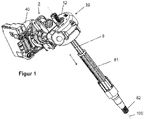
- the Figures 1 to 3 show a worm gear 1 as part of an electromechanical power steering system, which transmits an auxiliary torque from an electric motor 40 to a lower steering shaft 2.
- a worm wheel 3 is provided, which is non-rotatably connected to the lower steering shaft 2 .
- a rotation of the worm wheel 3 about its axis of rotation 100 causes an auxiliary force or an additional force to be applied to the steering shaft 2 in order to correspondingly introduce an auxiliary force or an additional steering angle into the steering train.
- the worm wheel 3 is driven via a worm 4, which in turn is driven via the electric motor 40, the output of the electric motor being coupled to the worm 4 accordingly for torque transmission.
- a Torque sensor unit 6 and a steering angle sensor unit 7 are provided in the figure 2 .
- the torque sensor unit 6 detects the twisting of an upper steering shaft 8 in relation to the lower steering shaft 2 as a measure of the torque exerted manually on the upper steering shaft 8 .
- the steering angle sensor unit 7 measures the current steering angle of the lower steering shaft 2 .
- An associated sensor unit 11 is held stationary.
- the upper steering shaft 8 is non-rotatable in a rear steering shaft part 81, but adjustable in the direction of the longitudinal axis 100, as indicated by the double arrow in figure 1 indicated in order to adjust a steering wheel attached to a fastening section 82, not shown here, in the longitudinal direction.
- the worm wheel 3 is rotatably mounted in a gear housing 12 on both of its end faces by means of a ball bearing 13 .
- the ball bearings 13 have an inner ring 14 , 140 connected to the lower steering shaft 2 and an outer ring 15 and rolling elements 16 seated in the gear housing 12 .
- the rolling bodies 16 run in grooves between the inner ring 14 , 140 and the outer ring 15 .
- the inner rings 14 , 140 have an inner cylindrical lateral surface for a tight fit on the lower steering shaft 2 .
- the outer rings 15 are each accommodated in a seat 17 in the transmission housing 12 .
- the seat 17 is formed in each case by an annular shoulder 18 in the transmission housing 12 running around the longitudinal axis 100 in the circumferential direction.
- the shoulders 18 serve as a contact surface, which extends in the radial direction to the longitudinal direction 100 and thus defines the orientation of the ball bearing 13 in the longitudinal direction 100 .
- the outer rings 15 thus bear against the transmission housing 12 with their end faces 19 remote from the worm wheel and their lateral surface 20 .
- the outer rings 15 are not in contact with the worm wheel 3.
- the inner rings 14, 140 are supported on the worm wheel 3 with their end faces 21 close to the worm wheel.
- a first inner ring 140 of a first bearing lies with its end face 21 close to the worm wheel directly in contact with a first end face of the worm wheel 3.
- a spring element 22 is provided, which applies a constant prestress to the peripheral/annular surface of the second inner ring 14 .
- the spring element 22 is in contact with the end face of the second inner ring 14 close to the worm wheel and engages in a recess 23 running around the longitudinal axis 100 in the circumferential direction in the second end face of the worm wheel 3 .
- the spring element 22 is formed by an annular base body 220, from the outer peripheral side 221 of which spring arms 222 extend at a uniform distance.
- the spring arms 222 each have a free end 223 .
- a first leg 222a of the spring arm 222 points outwards away from the longitudinal axis 100.
- the first leg 222a merges into a second leg 222b, which in this embodiment assumes a curved shape.
- the second leg is approximately parallel to the longitudinal axis 100 at its highest point or in its middle.
- the spring arms 222 widen in the circumferential direction towards the longitudinal axis up to a maximum width b1 and then run in an end region towards the free end 223 down to a minimum width b2.
- the base body 220 is in contact with the inner ring and the free ends of the spring arms 223 are supported on the worm wheel in the recess.
- the spring arms 222 protrude outwards from the annular base body 220 in the radial direction toward the longitudinal axis 100, with the spring arms 222 being bent or folded back inwards towards the center of the base body, so that their free ends 223 face each other toward the center.
- the spring arms 222 thus have an approximately U-shaped profile in longitudinal section along the longitudinal axis.
- the first leg 222a of the spring arms 222 which extends from the base body 220 and is essentially planar, encloses an angle ⁇ with the plane of the base body.
- the area with the maximum width b1 is located furthest outward in the radial direction and in the second leg 222b.
- the free ends 223 of the spring arms 222 go point away from the third leg 222c and are bent inwards from the center in the direction of the base body or in the direction of the longitudinal axis 100 in such a way that in the end area a contact surface 225 is formed on the upper side of the spring arms 222 with the minimum width b2, with which can support the spring arms on the worm wheel. Since the contact surface 225 is relatively large, the spring seat can be checked easily.
- the spring arms 222 are preferably drawn inward to such an extent that radial movement/preloading is possible.
- the annular base body 220 has a thickness d1 in the longitudinal direction.
- the entire spring element with the spring arms has an outer thickness d2, which in this exemplary embodiment comprises the first, second and third legs 222a-c.
- the maximum width b1 of the spring arms preferably assumes a value between 5mm and 12mm.
- the outer thickness d2 preferably assumes a value between 6.5 and 11 mm.
- the angle ⁇ preferably assumes a value between 10° and 30°.
- the sheet metal thickness d1 preferably assumes a value between 0.3 and 1 mm.
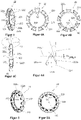
- the spring arms 222 are spaced apart from one another and are connected to one another exclusively via the base body. The spring arms are preferably connected in one piece to the base body.
- Figure 4d presents a partial view Figure 4C It shows that the second leg 222b runs almost parallel to the longitudinal axis.
- the second leg has an inner peripheral surface and an outer peripheral surface, the outer peripheral surface being located farther from the longitudinal axis than the inner peripheral surface and being contacted at the outer peripheral surface by a tangent 222b-1 parallel to the longitudinal axis.
- a secant 222b-2 parallel to this tangent 222b-1 is formed by the inner peripheral surface of the second leg 222b, the inner peripheral surface being arranged closer to the longitudinal axis 100 than the outer peripheral surface.
- the secant 222b-2 and the tangent 222b-1 run parallel to the longitudinal axis 100 and are spaced apart by a distance Dx, where Dx ⁇ 10 ⁇ d1 ⁇ d1, preferably Dx ⁇ 7 ⁇ d1 ⁇ 5 ⁇ d1. It is also shown that the first leg 222a and the third leg 222c each form a tangent away from the longitudinal axis. The second, curved leg 222b lies between these two tangents. In the point where these two When tangents intersect, a right angle is formed. The two tangents form the adjacent sides in relation to the right angle. The opposite side is formed by the tangent 222b-1 or by the secant 222b-2, so that two isosceles right-angled triangles are spanned.
- the Figures 5 to 5C show a further exemplary embodiment of a spring element 22, which essentially corresponds to the spring element described above, but in which the free ends 223 of the spring arms 222 are not additionally bent inwards.
- the end faces of the free ends 223 are thus in contact with the worm wheel 3 in the installed state.
- the free ends 223 of the spring arms 222 taper to a point up to the minimum width b2, as a result of which stresses during compression can be evenly distributed.
- the free ends 223 have a plastic coating 226 to prevent the spring arms 222 from wearing out.
- the spring arms 222 of the spring element 22 can, for example, be symmetrical to a plane that is spanned by the longitudinal axis 100, as in figure 7 shown, or offset in the circumferential direction about the longitudinal axis 100 by a defined angle about the spring center, as in figure 8 shown, take place.
- the base body 220 is inclined or has a curved shape in order to also contribute to the spring deflection.
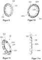
- a base body 220 is shown.
- essentially triangular, planar spring arms 222 extend from both sides of the base body 220 in the direction of the longitudinal axis 100.
- the spring arms on one side bear against the worm wheel and the spring arms on the other side the inner ring of the bearing.
- figure 10 shows another embodiment in which the ring-shaped base body 220 is almost wire-shaped and spring arms 222 with a U-shaped profile are connected to the base body 220 on one of their legs 222a-c on the outside, in this example the first leg 222a.
- the base body 220 is located in the central area of the first leg 222a, between its free end and between the second leg 222b.
- the spring arm 222 projects beyond the base body 220 in the direction of the longitudinal axis 100 .
- the spring arms 222 extend in the direction of the center of the spring.
- the spring element 22 consists only of the first leg 222a and the second leg 222b, as in Figure 11 and 11a is shown in order to allow a force-distributed and thus low-stress support in the longitudinal direction.
- the first leg 222a goes away from the base body 220 and extends in a substantially planar manner and encloses an angle ⁇ with respect to the base body 220 plane.
- the second leg 222b extends from the first leg 222a and forms the free end 223.
- the second leg is planar, as in FIG Figure 11a , shown, and thus formed parallel to the longitudinal axis.
- the first leg 222a and the second leg 222b span an angle ⁇ which is less than or equal to 180° and is greater than ⁇ .
- the first and second legs 222a, 222b preferably assume a V-shape as shown in FIG Figure 11a shown.
- the second leg 222b can also assume a curved shape, as in FIG figure 11 to see.
- the second leg forms a U-shape and is bent in such a way that the second leg 222b is approximately parallel to the longitudinal axis.
- the spring element is preferably designed in one piece, which simplifies assembly and prevents friction between component parts and the development of noise associated therewith.
- the spring element can also be designed in several parts.
- the spring element has a symmetrical load distribution (even if the load cannot be constant over the circumference). It can be manufactured by bending a single sheet metal part. Compared to disc springs, the basic concept of a bending beam allows low stress in the tangential direction can be realized. A movement of the spring on the spring seat in the radial direction is prevented, which leads to good NVH behavior.
- the ring-shaped base body does not have a mechanically closed connecting ring.
- the spring arms and possible bending lugs come from a linear base body.
- the base body is bent into a ring.
- the spring arms which are similar to a bending beam, are bent from the sheet metal part to form U-shaped spring elements, which are connected to one another via the base body.
- the base body can be flat or wavy in order to increase the spring deflection.
- the spring element can be designed as a sheet metal element by means of a rolling process or a press-bending process and can be coated with plastic. The use of anti-friction coating is also conceivable and possible.
- the spring element is particularly preferably designed in one piece, but it is conceivable and possible to design it in multiple parts.
Landscapes
- Engineering & Computer Science (AREA)
- General Engineering & Computer Science (AREA)
- Mechanical Engineering (AREA)
- Chemical & Material Sciences (AREA)
- Combustion & Propulsion (AREA)
- Transportation (AREA)
- Power Steering Mechanism (AREA)
- Gear Transmission (AREA)
- Gears, Cams (AREA)
Description
- Die vorliegende Erfindung betrifft ein elektromechanisches Lenksystem mit den Merkmalen des Oberbegriffs des Anspruchs 1.
- In elektromechanischen Lenksystemen wird über einen Elektromotor ein Drehmoment erzeugt, das auf ein Getriebe übertragen und dort dem vom Fahrer gestellten Lenkmoment überlagert wird.
- Eine gattungsgemäße elektromechanische Servolenkung weist einen elektrischen Servomotor auf, der eine Schneckenwelle antreibt, die mit einem auf einer Lenkwelle angeordneten Schneckenrad kämmt, wobei das Schneckenrad mit einer Eingangswelle eines Lenkgetriebes in Wirkverbindung steht und wobei die Schneckenwelle und die Lenkwelle in einem gemeinsamen Getriebegehäuse drehbar gelagert sind. Die Schneckenwelle ist mit der Motorwelle des elektrischen Servomotors über eine Kupplung verbunden.
- Das Lager des Schneckenrades wird mittels eines Vorspannelements in Form einer Feder in axialer und radialer Richtung abgestützt und vorgespannt, wie es beispielsweise aus der Schrift
JP 2001-280428 A - Es ist daher Aufgabe der vorliegenden Erfindung ein elektromechanisches Lenksystem mit einem Untersetzungsgetriebe anzugeben, das im Betrieb besonders geräuscharm ist und ein Vorspannelement eines Lagers aufweist, dass eine bessere Vorspannung und Lastverteilung bereitstellt.
- Diese Aufgabe wird von einem elektromechanischen Lenksystem mit den Merkmalen des Anspruchs 1 gelöst. Vorteilhafte Weiterbildungen ergeben sich aus den Unteransprüchen.
- Demnach ist ein elektromechanisches Lenksystem für ein Kraftfahrzeug, mit einem eine Schnecke und ein Schneckenrad umfassenden Untersetzungsgetriebe vorgesehen, wobei das Schneckenrad in einem Getriebegehäuse auf einer ersten Stirnseite in einem ersten Lager und auf einer zweiten Stirnseite in einem zweiten Lager um eine Längsachse drehbar gelagert ist, wobei beide Lager einen Außenring und einen Innenring aufweisen, zwischen denen Wälzkörper angeordnet sind, wobei die Innenringe auf einer von dem Schneckenrad angetriebenen Welle drehfest angeordnet sind und die Außenringe im Getriebegehäuse sitzen, und wobei in Richtung der Längsachse zwischen dem Innenring des zweiten Lagers und dem Schneckenrad ein Federelement angeordnet ist. Das Federelement weist einen zumindest teilringförmigen Grundkörper auf, der sich im eingebauten Zustand koaxial zur Längsachse erstreckt und von dessen Außenumfangsseite in Umfangsrichtung zur Längsachse beabstandete Federarme abgehen, wobei mindestens ein Federarm ein freies Ende aufweist, wobei der Federarm einen ersten Schenkel umfasst, welcher weg von der Längsachse weist, und einen zweiten Schenkel umfasst, welcher zumindest teilweise parallel zu der Längsachse verläuft, an welchem das freie Ende ausgebildet ist. Dadurch wird ermöglicht, dass in Längsrichtung eine kraftverteilte und damit spannungsarme Auflage bereitgestellt werden kann. Das Federelement mit den Federarmen kann eine gleichmäßige Vorspannung erzeugen ohne zu kippen, wodurch Geräusche reduziert werden können. Ein Ende des zweiten Schenkels weist eine andere axiale Position entlang der Längsachse als ein zweites Ende auf, wobei das zweite Ende bevorzugt weiter beabstandet zum Grundkörper ist als das erste Ende. Der zweite Schenkel verläuft zumindest teilweise parallel oder annährend parallel zur Längsachse. Es kann vorgesehen sein, dass lediglich ein Mittelabschnitt des zweiten Schenkels parallel zur Längsachse verläuft. Der zweite Schenkel kann planar oder abgerundet sein oder einen Winkel aufspannen. Der erste Schenkel und der zweite Schenkel spannen einen Winkel auf, welcher kleiner als 180° ist.
- Das Lager ist als Wälzlager ausgebildet, bevorzugt als Kugellager oder als Rollenlager. Das Untersetzungsgetriebe ist als Schneckengetriebe ausgebildet.
- Vorzugsweise weist der mindestens eine Federarm einen dritten Schenkel auf, welcher zur Längsachse hin weist und das freie Ende bildet. Der Federarm kann dabei vorzugsweise U-förmig oder V-förmig, topf-oder napfförmig ausgebildet sein. Es ist weiterhin denkbar und möglich, die Federarme W-förmig auszubilden.
- Vorzugsweise liegt der Grundkörper im eingebauten Zustand in Anlage mit einer schneckenradnahen Stirnseite des zweiten Innenrings. Das Wälzlager kann so vor Beschädigung durch die Federarme geschützt werden. Es ist bevorzugt, dass die Federarme im eingebauten Zustand an der dem zweiten Lager zugewandten Stirnseite des Schneckenrads anliegen, insbesondere an einer Ausnehmung des Schneckenrads, die in der dem zweiten Lager zugewandten Stirnseite angeordnet ist, so dass das Schneckenrad in Längsrichtung und Radialrichtung vorgespannt ist.
- Das Federelement ist vorzugsweise so ausgestaltet, dass sich die freien Enden der Federarme auf einer gemeinsamen Seite des Federelementes in Richtung der Längsachse erstrecken.
- In einer bevorzugten Ausführungsform ist der Grundkörper des Federelements ringförmig. Am ringförmigen Bereich des Grundkörpers können an der äußeren und/oder inneren Fläche Schlitze angeordnet sein, welche in Umfangsrichtung des Grundkörpers zueinander beabstandet sind. Dadurch kann eine verbesserte Vorspannung des Federelements ermöglicht werden. Der Grundkörper kann eben ausgebildet sein oder gewellt, um den Federweg zu erhöhen. Das Federelement kann als Blechelement mittels Rollierverfahren oder Press-Biegeverfahren ausgebildet sein und mit Kunststoff überzogen werden. Auch die Verwendung von Gleitlack ist denkbar und möglich. Das Federelement ist besonders bevorzugt einstückig ausgebildet, es ist jedoch denkbar und möglich dieses mehrteilig auszubilden.
- Es kann vorgesehen sein, dass die freien Enden der Federarme an dem Schneckenrad anliegen, dabei ist es bevorzugt, wenn die freien Enden der Federarme eine Kunststoffbeschichtung aufweisen und so vor Verschleiß geschützt werden.
- Es kann aber auch vorgesehen sein, dass die Federarme auf der Außenseite befindliche Kontaktflächen aufweisen, die jeweils durch weiter nach innen zum Grundkörper zurückgebogene Endbereich der Federarme gebildet sind, wobei diese Kontaktflächen in Anlage mit dem Schneckenrad stehen.
- Um die Lastverteilung gleichmäßig zu verteilen, sind die Federarme zumindest teilweise in Umfangsrichtung gleichmäßig beabstandet, insbesondere über den gesamten Umfang. Die Federarme sind dabei vorzugsweise symmetrisch zu einer Ebene, die durch die Längsachse aufgespannt ist oder in Umfangsrichtung um die Längsachse um einen definierten Winkel um den Federmittelpunkt versetzt, angeordnet.
- Es kann vorgesehen sein, dass auf der Innenumfangsseite des Grundkörpers in Längsrichtung orientierte Nasen angeordnet sind, die das Federelement auf der Welle zentrieren, eine Auflage in Längsrichtung ermöglichen sowie zur Verdrehsicherung vorgesehen sind.
- In einer bevorzugten Ausführungsform ist das Federelement einteilig ausgebildet und insbesondere aus einem Blechteil gefertigt. Die Fertigung kann mittels Rollierverfahren oder Press-Biegeverfahren erfolgen.
- Vorzugsweise weisen die Federarme im Längsschnitt entlang der Längsachse ein annähernd U-förmiges Profil auf. Es ist weiterhin denkbar und möglich die freien Enden der Federarme am Grundkörper zu schließen, beziehungsweise einen jeden Federarm rohrförmig auszubilden bzw. zu biegen. Besonders bevorzugt sind die Federarme im Längsschnitt asymmetrisch ausgebildet. Dadurch wird ermöglicht, dass keine Kräfte in Radialrichtung wirken und weiterhin die Steifigkeit des Grundkörpers kompensiert werden kann. Weiterhin ist es bevorzugt, dass die Federarme derart umgebogen sind, dass sie sich parallel zur Längsachse erstrecken, um in Längsrichtung eine kraftverteilte und damit spannungsarme Auflage zu ermöglichen. In einer vorteilhaften Ausführungsform weisen die Federarme einen ersten Schenkel auf, der sich von dem Grundkörper aus erstreckt und einen Winkel zur Ebene des Grundkörpers in einem Bereich von 10° bis 30° einschließt. Vorzugsweise weist der Grundkörper eine Dicke in Längsrichtung in einem Bereich von 0,3mm bis 1mm auf. Bevorzugt weist das gesamte Federelement mit den Federarmen eine äußere Dicke in einem Bereich von 6,5mm bis 11mm auf. Vorzugsweise weisen die Federarme eine maximale Breite in Umfangsrichtung in einem Bereich zwischen 5mm und 12mm auf. Es kann vorgesehen sein, dass die Federarme in ihrer Breite zulaufend zur Längsachse ausgestaltet sind, damit Spannungen beim Einfedern gleichmäßig verteilt werden.
- Vorzugsweise weist der zweite Schenkel eine Innenumfangsfläche und eine Außenumfangsfläche auf, wobei die Außenumfangsfläche weiter entfernt zu der Längsachse angeordnet ist als die Innenumfangsfläche und an der Außenumfangsfläche von einer zur Längsachse parallelen Tangente berührt wird. Eine zu dieser Tangente parallele Sekante ist durch die Innenumfangsfläche des zweiten Schenkels gebildet, wobei die Innenumfangsfläche näher zur Längsachse angeordnet ist als die Außenumfangsfläche. Die Sekante und die Tangente verlaufen parallel zur Längsachse und sind durch einen Abstand zueinander beabstandet, wobei Dx ≤ 10 · d1 ≥ d1, bevorzugt Dx ≤ 7 · d1 ≥5·d1, wobei d1 der Dicke des Grundkörpers entspricht. Ferner ist bevorzugt, dass vom ersten Schenkel und vom dritten Schenkel jeweils eine Tangente weg von der Längsachse gebildet wird. Zwischen diesen beiden Tangenten liegt der zweite, gebogene, Schenkel. In dem Punkt, wo sich diese beiden Tangenten schneiden, wird ein rechter Winkel gebildet. Die beiden Tangenten bilden, bezogen auf den rechten Winkel, die Ankatheten. Die Gegenkathete wird durch die Tangente oder durch die Sekante gebildet, sodass zwei gleichschenklig-rechtwinklige Dreiecke aufgespannt werden.
- In einer Ausführungsform ist der Grundkörper planar ausgebildet. Er kann aber auch angestellt sein bzw. eine gebogene, parabolische oder gewellte Form aufweisen und somit zum Federweg beitragen. Bevorzugt stehen von dem ringförmigen Grundkörper die Federarme in Radialrichtung zur Längsachse nach außen über, wobei die Federarme nach innen zur Grundkörpermitte zurück gebogen oder gekantet sind, so dass sie mit ihren freien Enden einander zur Mitte zugewandt sind.
- Es ist auch denkbar, dass der ringförmige Grundkörper keinen mechanisch geschlossenen Verbindungsring aufweist. In diesem Fall gehen die Federarme und mögliche Biegenasen von einem linearen Grundkörper ab. Bei der Herstellung wird der Grundkörper zu einem Ring gebogen. Die biegebalkenähnlichen Federarme werden aus dem Blechteil zu U-förmigen, V-förmigen - mit spitzem oder stumpfen Winkel -, topf- oder napfförmigen Federelementen gebogen, die über den Grundkörper miteinander verbunden sind.
- Es kann auch vorgesehen sein, dass der Grundkörper auf beiden Seiten Federarme aufweist, wobei die Federarme dann sowohl an dem Innenring des zweiten Wälzlagers als auch an dem Schneckenrad anliegen.
- Bevorzugte Ausführungsformen der Erfindung werden nachfolgend anhand der Zeichnungen näher erläutert. Gleichartige oder gleichwirkende Bauteile werden in den Figuren mit denselben Bezugszeichen bezeichnet. Es zeigen:
- Figur 1:
- eine räumliche Darstellung eines Schneckengetriebes einer elektromechanischen Servolenkung,
- Figur 2:
- eine weitere räumliche Darstellung eines Schneckengetriebes einer Servolenkung gemäß
Figur 1 , - Figur 3:
- einen Längsschnitt durch das Schneckengetriebe,
- Figur 4,4A,4B,4C:
- Ansichten eines Federelements,
- Figur 4d:
- ein vergrößerter Ausschnitt X zur
Figur 4C , - Figur 5,5A,5B,5C:
- Ansichten einer zweiten Ausführungsform eines Federelements,
- Figur 6,6A,6B:
- Ansichten einer dritten Ausführungsform eines Federelements,
- Figur 7:
- eine Draufsicht auf ein Federelement einer weiteren Ausführungsform,
- Figur 8:
- eine Draufsicht auf ein Federelement einer weiteren Ausführungsform,
- Figur 9:
- eine Rückansicht auf ein Federelement einer weiteren Ausführungsform,
- Figur 10:
- eine Rückansicht auf ein Federelement einer weiteren Ausführungsform,
- Figur 11:
- eine räumliche Ansicht auf ein Federelement einer weiteren Ausführungsform, sowie
- Figur 11a:
- eine Seitenansicht auf ein Federelement einer weiteren Ausführungsform.
- Die
Figuren 1 bis 3 zeigen ein Schneckengetriebe 1 als Teil einer elektromechanischen Hilfskraftlenkung, welche ein Hilfsdrehmoment von einem Elektromotor 40 auf eine untere Lenkwelle 2 überträgt. Ein Schneckenrad 3 ist vorgesehen, welches mit der unteren Lenkwelle 2 drehfest verbunden ist. Eine Drehung des Schneckenrades 3 um seine Rotationsachse 100 bewirkt den Eintrag einer Hilfskraft beziehungsweise einer Zusatzkraft auf die Lenkwelle 2, um entsprechend eine Hilfskraft beziehungsweise einen Zusatzlenkwinkel in den Lenkstrang einzubringen. - Das Schneckenrad 3 wird über eine Schnecke 4 angetrieben, welche ihrerseits über den Elektromotor 40 angetrieben ist, wobei der Abtrieb des Elektromotors entsprechend zur Drehmomentübertragung mit der Schnecke 4 gekoppelt ist. In der
Figur 2 ist weiterhin eine integrale Baueinheit 5 mit einer Drehmomentsensoreinheit 6 und einer Lenkwinkelsensoreinheit 7 vorgesehen. Die Drehmomentsensoreinheit 6 erfasst die Verdrehung einer oberen Lenkwelle 8 gegenüber der unteren Lenkwelle 2 als ein Maß des an der oberen Lenkwelle 8 manuell ausgeübten Drehmomentes. Die Lenkwinkelsensoreinheit 7 hingegen misst den aktuellen Lenkwinkel der unteren Lenkwelle 2. Die Drehmomentsensoreinheit 6 weist einen drehfest mit der oberen Lenkwelle 8 verbunden Ringmagneten 9 (Permanentmagneten) und Magnetflussleiter 10 auf. Eine dazugehörige Sensoreinheit 11 ist raumfest gehalten. Die obere Lenkwelle 8 ist in einem hinteren Lenkwellenteil 81 drehfest, aber in Richtung der Längsachse 100 verstellbar, wie mit dem Doppelpfeil inFigur 1 angedeutet, um ein an einem Befestigungsabschnitt 82 angebrachtes, hier nicht dargestelltes Lenkrad in Längsrichtung zu verstellen. - Wie in
Figur 3 dargestellt, ist das Schneckenrad 3 in einem Getriebegehäuse 12 auf seinen beiden Stirnseiten jeweils mittels eines Kugellagers 13 drehbar gelagert. Die Kugellager 13 weisen einen mit der unteren Lenkwelle 2 verbundenen Innenring 14,140 und einen im Getriebegehäuse 12 sitzenden Außenring 15 und Wälzkörper 16 auf. Die Wälzkörper 16 laufen in Rillen zwischen dem Innenring 14,140 und dem Außenring 15. Die Innenringe 14,140 weisen eine innenzylindrische Mantelfläche für einen Festsitz auf der unteren Lenkwelle 2 auf. Die Außenringe 15 sind jeweils in einem Sitz 17 in dem Getriebegehäuse 12 aufgenommen. Der Sitz 17 wird jeweils durch einen um die Längsachse 100 in Umfangsrichtung umlaufenden ringförmigen Absatz 18 im Getriebegehäuse 12 gebildet. Die Absätze 18 dienen als Anlagefläche, die sich in Radialrichtung zur Längsrichtung 100 erstreckt und somit die Orientierung des Kugellagers 13 in Längsrichtung 100 definiert. Die Außenringe 15 liegen somit mit ihren schneckenradfernen Stirnseiten 19 und ihrer Mantelfläche 20 am Getriebegehäuse 12 an. Die Außenringe 15 stehen nicht in Kontakt mit dem Schneckenrad 3. Die Innenringe 14,140 hingegen stützen sich mit ihren schneckenradnahen Stirnseiten 21 an dem Schneckenrad 3 ab. Ein erster Innenring 140 eines ersten Lagers liegt mit seiner schneckenradnahen Stirnseite 21 unmittelbar in Anlage mit einer ersten Stirnseite des Schneckenrades 3. Zwischen einem zweiten Innenring 14 eines zweiten Lagers und einer zweiten Stirnseite des Schneckenrads ist hingegen ein Federelement 22 vorgesehen, das eine konstante Vorspannung auf die umlaufende/ringförmige Fläche des zweiten Innenringes 14 aufbringt. Das Federelement 22 liegt in Anlage mit der schneckenradnahen Stirnseite des zweiten Innenrings 14 und greift in eine um die Längsachse 100 in Umfangsrichtung umlaufende Ausnehmung 23 in der zweiten Stirnseite des Schneckenrads 3 ein. - In den
Figuren 4 bis 4C ist ein erstes Beispiel eines Federelements 22 dargestellt. Das Federelement 22 ist durch einen ringförmigen Grundkörper 220 gebildet, von dessen Außenumfangsseite 221 im gleichmäßigen Abstand Federarme 222 abgehen. Die Federarme 222 weisen jeweils ein freies Ende 223 auf. Vom Grundkörper 220 ausgehend weist ein erster Schenkel 222a des Federarms 222 nach außen hin weg von der Längsachse 100. Der erste Schenkel 222a geht in einen zweiten Schenkel 222b über, welcher in dieser Ausführungsform eine gebogene Form annimmt. Der zweite Schenkel ist in seinem höchsten Punkt oder in seiner Mitte annährend parallel zu der Längsachse 100. Der zweite Schenkel geht in einen dritten Schenkel 222c des Federarms 222 über, welcher zur Längsachse 100 hinweist. Von dem Grundkörper 220 ausgehend verbreitern sich die Federarme 222 in Umfangsrichtung zur Längsachse bis auf eine maximale Breite b1 und laufen dann in einem Endbereich zum freien Ende 223 hin bis auf eine minimale Breite b2 zu. Der Grundkörper 220 liegt im eingebauten Zustand in Anlage mit dem Innenring und die freien Enden der Federarme 223 stützen sich am Schneckenrad in der Ausnehmung ab. - Von dem ringförmigen Grundkörper 220 stehen die Federarme 222 in Radialrichtung zur Längsachse 100 nach außen über, wobei die Federarme 222 nach innen zur Grundkörpermitte zurück gebogen oder gekantet sind, so dass sie mit ihren freien Enden 223 einander zur Mitte zugewandt sind. Die Federarme 222 weisen somit im Längsschnitt entlang der Längsachse ein annähernd U-förmiges Profil auf. Der erste Schenkel 222a der Federarme 222, der sich von dem Grundkörper 220 aus erstreckt und im Wesentlichen planar ist, schließt einen Winkel α zur Ebene des Grundkörpers ein. Der Bereich mit der maximalen Breite b1 liegt in Radialrichtung am weitesten außen und im zweiten Schenkel 222b. Die freien Enden 223 der Federarme 222 gehen weisen vom dritten Schenkel 222c ab und sind aus der Mitte in Richtung des Grundkörpers beziehungsweise in Richtung der Längsachse 100 nach innen umgebogen, derart, dass sich im Endbereich eine Anlagefläche 225 auf der Oberseite der Federarme 222 mit der minimalen Breite b2 ausbildet, mit der sich die Federarme am Schneckenrad abstützen können. Da die Anlagefläche 225 relativ groß ist, lässt sich der Federsitz gut kontrollieren. Die Federarme 222 sind bevorzugt soweit nach innen gezogen, dass eine radiale Bewegung/Vorspannung möglich ist. Der ringförmige Grundkörper 220 weist eine Dicke d1 in Längsrichtung auf. Das gesamte Federelement mit den Federarmen weist eine äußere Dicke d2 auf, welche in diesem Ausführungsbeispiel den ersten, zweiten und dritten Schenkel 222a-c umfasst. Die maximale Breite b1 der Federarme nimmt bevorzugt einen Wert zwischen 5mm und 12mm an. Die äußere Dicke d2 nimmt bevorzugt einen Wert zwischen 6,5 und 11mm an. Der Winkel α nimmt bevorzugt einen Wert zwischen 10° und 30° an. Die Blechdicke d1 nimmt bevorzugt einen Wert zwischen 0,3 und 1mm an. Die Federarme 222 sind zueinander beabstandet und sind ausschließlich über den Grundkörper miteinander verbunden. Bevorzugt sind die Federarme einstückig an den Grundkörper angebunden.
-
Figur 4d stellt eine Teilansicht ausFigur 4C dar. Darin ist dargestellt, dass der zweite Schenkel 222b nahezu parallel zu der Längsachse verläuft. Der zweite Schenkel weist eine Innenumfangsfläche und eine Außenumfangsfläche auf, wobei die Außenumfangsfläche weiter entfernt zu der Längsachse angeordnet ist als die Innenumfangsfläche und an der Außenumfangsfläche von einer zur Längsachse parallelen Tangente 222b-1 berührt wird. Eine zu dieser Tangente 222b-1 parallele Sekante 222b-2 ist durch die Innenumfangsfläche des zweiten Schenkels 222b gebildet, wobei die Innenumfangsfläche näher zur Längsachse 100 angeordnet ist als die Außenumfangsfläche. Die Sekante 222b-2 und die Tangente 222b-1 verlaufen parallel zur Längsachse 100 und sind durch einen Abstand Dx zueinander beabstandet, wobei Dx ≤ 10 · d1 ≥ d1, bevorzugt Dx ≤ 7 · d1 ≥5·d1. Weiterhin ist dargestellt, dass vom ersten Schenkel 222a und vom dritten Schenkel 222c jeweils eine Tangente weg von der Längsachse gebildet wird. Zwischen diesen beiden Tangenten liegt der zweite, gebogene, Schenkel 222b. In dem Punkt, wo sich diese beiden Tangenten schneiden, wird ein rechter Winkel gebildet. Die beiden Tangenten bilden, bezogen auf den rechten Winkel, die Ankatheten. Die Gegenkathete wird durch die Tangente 222b-1 oder durch die Sekante 222b-2 gebildet, sodass zwei gleichschenklig-rechtwinklige Dreiecke aufgespannt werden. - Die
Figuren 5 bis 5C zeigen ein weiteres Ausführungsbeispiel eines Federelements 22, das im Wesentlichen dem zuvor beschrieben Federelement entspricht, aber bei dem die freien Enden 223 der Federarme 222 nicht zusätzlich nach innen gebogen sind. Die Stirnflächen der freien Enden 223 liegen somit im eingebauten Zustand an dem Schneckenrad 3 an. Die freien Enden 223 der Federarme 222 laufen spitz bis zu der minimal Breite b2 zu, wodurch Spannungen beim Einfedern gleichmäßig verteilt werden können. Die freien Enden 223 weisen einen Kunststoffüberzug 226 auf, um einen Verschleiß der Federarme 222 zu verhindern. - Hingegen wird in dem Ausführungsbeispiel der
Figuren 6 bis 6B auf den Kunststoffüberzug verzichtet. Hier sind auf einer Innenumfangsseite 227 des ringförmigen Grundkörpers 220 in Längsrichtung orientierte Biegenasen 228 zur Zentrierung des Federelements 22 auf der äußeren Lenkwelle sowie zur Verdrehsicherung vorgesehen. - Es ist auch denkbar die Federarme 222 des Federelements 22 in nur teilweise regelmäßigen Abständen in Umfangsrichtung des Grundkörpers 220 anzuordnen, wie dies in den
Figuren 7 und 8 dargestellt ist. Die Anordnung kann dabei beispielsweise symmetrisch zu einer Ebene, die durch die Längsachse 100 aufgespannt ist, wie inFigur 7 dargestellt, oder in Umfangsrichtung um die Längsachse 100, um einen definierten Winkel um den Federmittelpunkt versetzt, wie inFigur 8 dargestellt, erfolgen. - Es kann auch vorgesehen sein, dass der Grundkörper 220 angestellt ist bzw. eine gebogene Form aufweist um ebenfalls zum Federweg beizutragen. In der
Figur 9 ist ein solcher Grundköper 220 dargestellt. In dem gezeigten Ausführungsbeispiel erstrecken sich von beiden Seiten des Grundkörpers 220 im Wesentlichen dreieckige, planare Federarme 222 in Richtung der Längsachse 100. Bei diesem Ausführungsbeispielen liegen die Federarme der einen Seite an dem Schneckenrad und die Federarme der anderen Seite an dem Innenring des Lagers an. -
Figur 10 zeigt ein weiteres Ausführungsbeispiel, bei dem der ringförmige Grundkörper 220 beinahe drahtförmig ausgestaltet ist und im Profil U-förmige Federarme 222 an einem ihrer Schenkel 222a-c auf der Außenseite mit dem Grundkörper 220 verbunden sind, in diesem Beispiel der erste Schenkel 222a. Dabei liegt der Grundkörper 220 im Mittenbereich des ersten Schenkels 222a, zwischen dessen freien Ende und zwischen dem zweiten Schenkel 222b. Der Federarm 222 ragt dabei über den Grundkörper 220 in Richtung der Längsachse 100 über. Die Federarme 222 erstrecken sich, wie bei den anderen Ausführungsformen in Richtung der Federmitte. - Es ist weiterhin bevorzugt, dass das Federelement 22 nur aus dem ersten Schenkel 222a und dem zweiten Schenkel 222b besteht, wie in
Figur 11 und 11a dargestellt ist, um in Längsrichtung eine kraftverteilte und damit spannungsarme Auflage zu ermöglichen. Dabei geht der erste Schenkel 222a vom Grundkörper 220 weg und erstreckt sich im Wesentlichen planar und schließt einen Winkel α zur Ebene des Grundkörpers 220 ein. Vom ersten Schenkel 222a geht der zweite Schenkel 222b ab und bildet das freie Ende 223. Der zweite Schenkel ist dabei planar, wie inFigur 11a , dargestellt, und damit parallel zur Längsachse ausgebildet. Der erste Schenkel 222a und der zweite Schenkel 222b spannen dabei einen Winkel β auf, welcher kleiner oder gleich 180° ist und grösser als α ist. Der erste und der zweite Schenkel 222a, 222b nehmen bevorzugt eine V-Form an, wie inFigur 11a dargestellt. Der zweite Schenkel 222b kann auch eine gebogene Form annehmen, wie inFigur 11 zu sehen. Dabei bildet der zweite Schenkel eine U-Form und ist in derart gebogen, dass der zweite Schenkel 222b annährend parallel zur Längsachse ist. Bevorzugt ist das Federelement einteilig ausgebildet, was die Montage vereinfacht und eine Reibung zwischen Bauteilkomponenten und eine damit einhergehende Geräuschentwicklung verhindert. Das Federelement kann aber auch mehrteilig ausgebildet sein. Zudem weist das Federelement eine symmetrische Lastverteilung (auch wenn die Last über den Umfang nicht konstant sein kann) auf. Die Herstellung kann durch einen Biegeprozess eines einzigen Blechteils erfolgen. Im Vergleich zu Tellerfedern kann bei dem Grundkonzept eines Biegebalkens eine niedrige Spannung in tangentialer Richtung realisiert werden. Eine Bewegung der Feder auf dem Federsitz in radialer Richtung wird unterbunden, was zu einem guten NVH-Verhalten führt. - Es ist auch denkbar, dass der ringförmige Grundkörper keinen mechanisch geschlossenen Verbindungsring aufweist. In diesem Fall gehen die Federarme und mögliche Biegenasen von einem linearen Grundkörper ab. Bei der Herstellung wird der Grundkörper zu einem Ring gebogen. Die biegebalkenähnlichen Federarme werden aus dem Blechteil zu U-förmigen FederElementen gebogen, die über den Grundkörper miteinander verbunden sind.
- Der Grundkörper kann eben ausgebildet sein oder gewellt, um den Federweg zu erhöhen. Das Federelement kann als Blechelement mittels Rollierverfahren oder Press-Biegeverfahren ausgebildet sein und mit Kunststoff überzogen werden. Auch die Verwendung von Gleitlack ist denkbar und möglich. Das Federelement ist besonders bevorzugt einstückig ausgebildet, es ist jedoch denkbar und möglich dieses mehrteilig auszubilden.
- Es ist weiterhin denkbar und möglich die freien Enden der Federarme zu schließen, um damit eine vereinfachte Montage zu gewährleisten, da sich dadurch beispielsweise kein Schüttgut verfangen kann.
- Durch die erfindungsgemäße Feder kann ein Axialspiel, Toleranzen und Wärmeausdehnungen ausgeglichen werden.
Claims (19)
- Elektromechanisches Lenksystem für ein Kraftfahrzeug, mit einem eine Schnecke (4) und ein Schneckenrad (3) umfassenden Untersetzungsgetriebe (1), wobei das Schneckenrad (3) in einem Getriebegehäuse (12) auf einer ersten Stirnseite in einem ersten Lager (13) und auf einer zweiten Stirnseite in einem zweiten Lager (13) um eine Längsachse (100) drehbar gelagert ist, wobei beide Lager (13) einen Außenring (15) und einen Innenring (14,140) aufweisen, zwischen denen Wälzkörper (16) angeordnet sind, wobei die Innenringe (14,140) auf einer von dem Schneckenrad (3) angetriebenen Welle (2) drehfest angeordnet sind und die Außenringe (15) im Getriebegehäuse (12) sitzen, und wobei in Richtung der Längsachse (100) zwischen dem Innenring (140) des zweiten Lagers (13) und dem Schneckenrad (3) ein Federelement (22) angeordnet ist, dadurch gekennzeichnet, dass das Federelement (22) einen zumindest teilringförmigen Grundkörper (220) aufweist, der sich im eingebauten Zustand koaxial zur Längsachse (100) erstreckt und von dessen Außenumfangsseite (221) in Umfangsrichtung zur Längsachse (100) beabstandete Federarme (222) abgehen, wobei mindestens ein Federarm (222) ein freies Ende (223) aufweist, wobei der Federarm einen ersten Schenkel (222a) umfasst, welcher weg von der Längsachse (100) weist, und einen zweiten Schenkel (222b) umfasst, welcher zumindest teilweise parallel zu der Längsachse (100) verläuft, an welchem das freie Ende (223) ausgebildet ist.
- Elektromechanisches Lenksystem nach Anspruch 1, dadurch gekennzeichnet, dass der mindestens eine Federarm (222) einen dritten Schenkel (222c) umfasst, welcher zur Längsachse (100) hin weist und welcher das freie Ende (223) bildet.
- Elektromechanisches Lenksystem nach Anspruch 1 oder 2, dadurch gekennzeichnet, dass der Grundkörper (220) im eingebauten Zustand in Anlage mit einer schneckenradnahen Stirnseite des zweiten Innenrings (140) steht.
- Elektromechanisches Lenksystem nach Anspruch 1 bis 3, dadurch gekennzeichnet, dass die Federarme (222) im eingebauten Zustand an der dem zweiten Lager (13) zugewandten Stirnseite des Schneckenrads (3) anliegen.
- Elektromechanisches Lenksystem nach einem der vorhergehenden Ansprüche, dadurch gekennzeichnet, dass sich die freien Enden (223) der Federarme (222) auf einer gemeinsamen Seite des Federelementes (22) in Richtung der Längsachse (100) erstrecken.
- Elektromechanisches Lenksystem nach einem der vorhergehenden Ansprüche, dadurch gekennzeichnet, dass der Grundkörper (220) des Federelements (22) ringförmig ist.
- Elektromechanisches Lenksystem nach einem der vorhergehenden Ansprüche, dadurch gekennzeichnet, dass die Federarme (222) an einer Ausnehmung (23) des Schneckenrads (3), die in der dem zweiten Lager (13) zugewandten Stirnseite angeordnet ist, anliegen und das Schneckenrad (3) in Längsrichtung und Radialrichtung vorspannen.
- Elektromechanisches Lenksystem nach einem der vorhergehenden Ansprüche, dadurch gekennzeichnet, dass die freien Enden (223) der Federarme (222) an dem Schneckenrad (3) anliegen.
- Elektromechanisches Lenksystem nach einem der vorhergehenden Ansprüche, dadurch gekennzeichnet, dass die freien Enden (223) der Federarme (222) eine Kunststoffbeschichtung aufweisen.
- Elektromechanisches Lenksystem nach einem der vorhergehenden Ansprüche, dadurch gekennzeichnet, dass die Federarme (222) zumindest teilweise in Umfangsrichtung gleichmäßig beabstandet sind.
- Elektromechanisches Lenksystem nach einem der vorhergehenden Ansprüche, dadurch gekennzeichnet, dass auf der Innenumfangsseite (227) des Grundkörpers (220) in Längsrichtung (100) orientierte Nasen (228) angeordnet sind, die das Federelement (22) auf der Welle (2) zentrieren.
- Elektromechanisches Lenksystem nach einem der vorhergehenden Ansprüche, dadurch gekennzeichnet, dass das Federelement (22) einteilig ausgebildet ist und aus einem Blechteil gefertigt ist.
- Elektromechanisches Lenksystem nach einem der vorhergehenden Ansprüche, dadurch gekennzeichnet, dass die Federarme (222) im Längsschnitt entlang der Längsachse (100) ein annähernd U-förmiges Profil aufweisen.
- Elektromechanisches Lenksystem nach einem der vorhergehenden Ansprüche, dadurch gekennzeichnet, dass der erste Schenkel (222a) der Federarme (222), der sich von dem Grundkörper (220) aus erstreckt und im Wesentlichen planar ist, einen Winkel (α) zur Ebene des Grundkörpers (220) in einem Bereich von 10° bis 30° einschließt.
- Elektromechanisches Lenksystem nach einem der vorhergehenden Ansprüche, dadurch gekennzeichnet, dass der Grundkörper (220) eine Dicke (d1) in Längsrichtung in einem Bereich von 0,3 bis 1mm aufweist.
- Elektromechanisches Lenksystem nach einem der vorhergehenden Ansprüche, dadurch gekennzeichnet, dass das gesamte Federelement (22) mit den Federarmen (222) eine äußere Dicke (d2) in einem Bereich von 6,5 bis 11mm aufweist.
- Elektromechanisches Lenksystem nach einem der vorhergehenden Ansprüche, dadurch gekennzeichnet, dass die Federarme (222) eine maximale Breite (b1) in Umfangsrichtung in einem Bereich zwischen 5mm und 12mm aufweisen.
- Elektromechanisches Lenksystem nach einem der vorhergehenden Ansprüche, dadurch gekennzeichnet, dass die Federarme (222) in ihrer Breite zulaufend zur Längsachse (100) ausgestaltet sind.
- Elektromechanisches Lenksystem nach einem der vorhergehenden Ansprüche, dadurch gekennzeichnet, dass der Grundkörper (220) planar ist.
Applications Claiming Priority (2)
| Application Number | Priority Date | Filing Date | Title |
|---|---|---|---|
| DE102018125887.9A DE102018125887B4 (de) | 2018-10-18 | 2018-10-18 | Federelement für ein Untersetzungsgetriebe eines elektromechanischen Lenksystems |
| PCT/EP2019/078105 WO2020079090A1 (de) | 2018-10-18 | 2019-10-16 | Federelement für ein untersetzungsgetriebe eines elektromechanischen lenksystems |
Publications (2)
| Publication Number | Publication Date |
|---|---|
| EP3867124A1 EP3867124A1 (de) | 2021-08-25 |
| EP3867124B1 true EP3867124B1 (de) | 2022-09-14 |
Family
ID=68290238
Family Applications (1)
| Application Number | Title | Priority Date | Filing Date |
|---|---|---|---|
| EP19790184.6A Active EP3867124B1 (de) | 2018-10-18 | 2019-10-16 | Elektromechanisches lenksystem mit einem federelement für ein untersetzungsgetriebe des lenksystems |
Country Status (5)
| Country | Link |
|---|---|
| US (1) | US11820441B2 (de) |
| EP (1) | EP3867124B1 (de) |
| CN (1) | CN112867659B (de) |
| DE (1) | DE102018125887B4 (de) |
| WO (1) | WO2020079090A1 (de) |
Families Citing this family (4)
| Publication number | Priority date | Publication date | Assignee | Title |
|---|---|---|---|---|
| DE102020208584A1 (de) | 2020-07-08 | 2022-01-13 | Thyssenkrupp Ag | Hilfskraftlenkung für ein Kraftfahrzeug |
| GB2600727B (en) * | 2020-11-06 | 2023-05-10 | Continental Automotive Romania Srl | Preloading bearing element |
| US20220307549A1 (en) * | 2021-03-25 | 2022-09-29 | Zf Active Safety And Electronics Us Llc | Multi-spring rate washer |
| DE102021210064A1 (de) | 2021-09-13 | 2023-03-16 | Joyson Safety Systems Germany Gmbh | Rückstellmomenterzeugungseinrichtung für eine Lenkvorrichtung eines Kraftfahrzeuges |
Family Cites Families (23)
| Publication number | Priority date | Publication date | Assignee | Title |
|---|---|---|---|---|
| US4739855A (en) * | 1985-07-22 | 1988-04-26 | Mazda Motor Corporation | Vehicle steering system having a steering ratio changing mechanism |
| JPS6470267A (en) * | 1987-09-11 | 1989-03-15 | Koyo Seiko Co | Power steering device |
| US5709516A (en) * | 1994-04-18 | 1998-01-20 | General Electric Company | Washer faced spring assembly |
| DE19811784A1 (de) | 1998-03-18 | 1999-09-23 | Mannesmann Vdo Ag | Elektrische Lenkhilfe |
| JP3329294B2 (ja) | 1998-12-28 | 2002-09-30 | 日本精工株式会社 | コイル組立体の固定構造及び電動式パワーステアリング装置 |
| JP2001280428A (ja) | 2000-03-31 | 2001-10-10 | Toyoda Mach Works Ltd | ウオームギヤ装置 |
| JP4516431B2 (ja) | 2004-04-26 | 2010-08-04 | 本田技研工業株式会社 | ウォームギヤ機構及びウォームギヤ機構を搭載した電動パワーステアリング装置 |
| DE102004049105B4 (de) | 2004-10-07 | 2006-11-02 | Ims Gear Gmbh | Lagerelement |
| JP2008296633A (ja) | 2007-05-29 | 2008-12-11 | Nsk Ltd | 電動パワーステアリング装置用の電動アシスト機構 |
| DE102010002569A1 (de) | 2009-03-26 | 2010-09-30 | Zf Lenksysteme Gmbh | Lenkgetriebe und damit ausgestattete Servolenkung |
| JP2013071679A (ja) * | 2011-09-28 | 2013-04-22 | Showa Corp | 電動パワーステアリング装置 |
| AT512609A1 (de) | 2012-09-14 | 2013-09-15 | Hoerbiger Kompressortech Hold | Federelement |
| DE102013101045B3 (de) | 2013-02-01 | 2014-05-15 | Thyssenkrupp Presta Aktiengesellschaft | Lenksäule für ein Kraftfahrzeug |
| DE102013213708A1 (de) * | 2013-07-12 | 2015-01-15 | Volkswagen Aktiengesellschaft | Schneckengetriebe für eine Lenkhilfevorrichtung eines Kraftfahrzeuges mit Spielausgleich |
| JP2015031388A (ja) | 2013-08-07 | 2015-02-16 | オイレス工業株式会社 | 電動パワーステアリング装置に使用される弾性部材及び該弾性部材を有する電動パワーステアリング装置 |
| JP6264880B2 (ja) | 2013-12-25 | 2018-01-24 | 日本精工株式会社 | 電動式パワーステアリング装置 |
| US9895779B2 (en) | 2014-04-10 | 2018-02-20 | Temper Axle Products Corporation | Radial springs and methods of installing and uninstalling radial springs |
| US9769974B2 (en) * | 2014-06-24 | 2017-09-26 | Deere & Company | Combination C-shaped spring and system |
| DE102014110306A1 (de) | 2014-07-22 | 2016-01-28 | Thyssenkrupp Ag | Elektromechanische Servolenkung |
| JP6108358B2 (ja) * | 2014-07-23 | 2017-04-05 | 株式会社ショーワ | ウォーム付勢構造体 |
| JP6569892B2 (ja) * | 2015-04-30 | 2019-09-04 | 株式会社ジェイテクト | ウォーム減速機およびステアリング装置 |
| DE102017200213B4 (de) | 2017-01-09 | 2018-12-20 | Thyssenkrupp Ag | Motorisch verstellbare Lenksäule für ein Kraftfahrzeug |
| JP6876249B2 (ja) * | 2017-04-19 | 2021-05-26 | 株式会社ジェイテクト | ウォーム減速機および電動パワーステアリング装置 |
-
2018
- 2018-10-18 DE DE102018125887.9A patent/DE102018125887B4/de not_active Expired - Fee Related
-
2019
- 2019-10-16 US US17/284,818 patent/US11820441B2/en active Active
- 2019-10-16 CN CN201980068199.2A patent/CN112867659B/zh active Active
- 2019-10-16 EP EP19790184.6A patent/EP3867124B1/de active Active
- 2019-10-16 WO PCT/EP2019/078105 patent/WO2020079090A1/de not_active Ceased
Also Published As
| Publication number | Publication date |
|---|---|
| DE102018125887A1 (de) | 2020-04-23 |
| DE102018125887B4 (de) | 2023-02-16 |
| US11820441B2 (en) | 2023-11-21 |
| CN112867659A (zh) | 2021-05-28 |
| WO2020079090A1 (de) | 2020-04-23 |
| CN112867659B (zh) | 2023-06-13 |
| US20210339795A1 (en) | 2021-11-04 |
| EP3867124A1 (de) | 2021-08-25 |
Similar Documents
| Publication | Publication Date | Title |
|---|---|---|
| DE102018125887B4 (de) | Federelement für ein Untersetzungsgetriebe eines elektromechanischen Lenksystems | |
| DE102010054828A1 (de) | Servolenkung mit Spindeltrieb | |
| DE4440725A1 (de) | Lageranordnung zur spielfreien Einstellung einer Welle, insbesondere einer Lenkwelle in einer Lenksäule | |
| EP2199639B1 (de) | Scheibenbremse für ein Nutzfahrzeug | |
| DE102013213708A1 (de) | Schneckengetriebe für eine Lenkhilfevorrichtung eines Kraftfahrzeuges mit Spielausgleich | |
| DE102016219919A1 (de) | Elastisches Zahnrad eines Wellgetriebes | |
| DE102019118064A1 (de) | Lenksystem | |
| WO2001089909A1 (de) | Teleskopmechanismus | |
| EP3984764B1 (de) | Freilaufnabe mit feder aus kunststoff mit zelliger struktur | |
| EP1978275B1 (de) | Gelenklager, insbesondere an einem Drehgelenk zwischen einem Vorderwagen und Hinterwagen eines Gelenkbusses | |
| DE10113442C2 (de) | Lageranordnung für ein Wellenlager | |
| EP2606245A1 (de) | Radiallager zum lagern einer welle | |
| DE19637120C1 (de) | Differentialgetriebe für ein Kraftfahrzeug | |
| EP1691104B1 (de) | Elastisches Lager | |
| DE19542072A1 (de) | Kupplungsfederelement | |
| DE102008016798B4 (de) | Wälzlager sowie Lenkgetriebe mit einem derartigen Wälzlager | |
| AT520308B1 (de) | Zahnradgetriebe | |
| DE102012107857B4 (de) | Lagerbuchse | |
| WO2013110439A1 (de) | Positioniervorrichtung, insbesondere für einen gurtbringer, und gurtschlossvorrichtung | |
| WO2012072169A1 (de) | Tripode-rollelement mit federring | |
| EP3775587B1 (de) | Schwenkmotor eines aktiven wankstabilisators | |
| EP1637367B1 (de) | Federteller | |
| WO2017194046A1 (de) | Stellantrieb | |
| EP1820994B1 (de) | Gelenklager, insbesondere für ein Fahrwerk eines Nutzfahrzeugs | |
| DE20014397U1 (de) | Teleskopmechanismus |
Legal Events
| Date | Code | Title | Description |
|---|---|---|---|
| STAA | Information on the status of an ep patent application or granted ep patent |
Free format text: STATUS: UNKNOWN |
|
| STAA | Information on the status of an ep patent application or granted ep patent |
Free format text: STATUS: THE INTERNATIONAL PUBLICATION HAS BEEN MADE |
|
| PUAI | Public reference made under article 153(3) epc to a published international application that has entered the european phase |
Free format text: ORIGINAL CODE: 0009012 |
|
| STAA | Information on the status of an ep patent application or granted ep patent |
Free format text: STATUS: REQUEST FOR EXAMINATION WAS MADE |
|
| 17P | Request for examination filed |
Effective date: 20210518 |
|
| AK | Designated contracting states |
Kind code of ref document: A1 Designated state(s): AL AT BE BG CH CY CZ DE DK EE ES FI FR GB GR HR HU IE IS IT LI LT LU LV MC MK MT NL NO PL PT RO RS SE SI SK SM TR |
|
| DAV | Request for validation of the european patent (deleted) | ||
| DAX | Request for extension of the european patent (deleted) | ||
| GRAP | Despatch of communication of intention to grant a patent |
Free format text: ORIGINAL CODE: EPIDOSNIGR1 |
|
| STAA | Information on the status of an ep patent application or granted ep patent |
Free format text: STATUS: GRANT OF PATENT IS INTENDED |
|
| INTG | Intention to grant announced |
Effective date: 20220523 |
|
| GRAS | Grant fee paid |
Free format text: ORIGINAL CODE: EPIDOSNIGR3 |
|
| GRAA | (expected) grant |
Free format text: ORIGINAL CODE: 0009210 |
|
| STAA | Information on the status of an ep patent application or granted ep patent |
Free format text: STATUS: THE PATENT HAS BEEN GRANTED |
|
| AK | Designated contracting states |
Kind code of ref document: B1 Designated state(s): AL AT BE BG CH CY CZ DE DK EE ES FI FR GB GR HR HU IE IS IT LI LT LU LV MC MK MT NL NO PL PT RO RS SE SI SK SM TR |
|
| REG | Reference to a national code |
Ref country code: GB Ref legal event code: FG4D Free format text: NOT ENGLISH |
|
| REG | Reference to a national code |
Ref country code: CH Ref legal event code: EP |
|
| REG | Reference to a national code |
Ref country code: DE Ref legal event code: R096 Ref document number: 502019005682 Country of ref document: DE |
|
| REG | Reference to a national code |
Ref country code: IE Ref legal event code: FG4D Free format text: LANGUAGE OF EP DOCUMENT: GERMAN |
|
| REG | Reference to a national code |
Ref country code: AT Ref legal event code: REF Ref document number: 1518535 Country of ref document: AT Kind code of ref document: T Effective date: 20221015 |
|
| REG | Reference to a national code |
Ref country code: DE Ref legal event code: R084 Ref document number: 502019005682 Country of ref document: DE |
|
| REG | Reference to a national code |
Ref country code: LT Ref legal event code: MG9D |
|
| REG | Reference to a national code |
Ref country code: NL Ref legal event code: MP Effective date: 20220914 |
|
| PG25 | Lapsed in a contracting state [announced via postgrant information from national office to epo] |
Ref country code: SE Free format text: LAPSE BECAUSE OF FAILURE TO SUBMIT A TRANSLATION OF THE DESCRIPTION OR TO PAY THE FEE WITHIN THE PRESCRIBED TIME-LIMIT Effective date: 20220914 Ref country code: RS Free format text: LAPSE BECAUSE OF FAILURE TO SUBMIT A TRANSLATION OF THE DESCRIPTION OR TO PAY THE FEE WITHIN THE PRESCRIBED TIME-LIMIT Effective date: 20220914 Ref country code: NO Free format text: LAPSE BECAUSE OF FAILURE TO SUBMIT A TRANSLATION OF THE DESCRIPTION OR TO PAY THE FEE WITHIN THE PRESCRIBED TIME-LIMIT Effective date: 20221214 Ref country code: LV Free format text: LAPSE BECAUSE OF FAILURE TO SUBMIT A TRANSLATION OF THE DESCRIPTION OR TO PAY THE FEE WITHIN THE PRESCRIBED TIME-LIMIT Effective date: 20220914 Ref country code: LT Free format text: LAPSE BECAUSE OF FAILURE TO SUBMIT A TRANSLATION OF THE DESCRIPTION OR TO PAY THE FEE WITHIN THE PRESCRIBED TIME-LIMIT Effective date: 20220914 Ref country code: FI Free format text: LAPSE BECAUSE OF FAILURE TO SUBMIT A TRANSLATION OF THE DESCRIPTION OR TO PAY THE FEE WITHIN THE PRESCRIBED TIME-LIMIT Effective date: 20220914 |
|
| PG25 | Lapsed in a contracting state [announced via postgrant information from national office to epo] |
Ref country code: HR Free format text: LAPSE BECAUSE OF FAILURE TO SUBMIT A TRANSLATION OF THE DESCRIPTION OR TO PAY THE FEE WITHIN THE PRESCRIBED TIME-LIMIT Effective date: 20220914 Ref country code: GR Free format text: LAPSE BECAUSE OF FAILURE TO SUBMIT A TRANSLATION OF THE DESCRIPTION OR TO PAY THE FEE WITHIN THE PRESCRIBED TIME-LIMIT Effective date: 20221215 |
|
| PG25 | Lapsed in a contracting state [announced via postgrant information from national office to epo] |
Ref country code: SM Free format text: LAPSE BECAUSE OF FAILURE TO SUBMIT A TRANSLATION OF THE DESCRIPTION OR TO PAY THE FEE WITHIN THE PRESCRIBED TIME-LIMIT Effective date: 20220914 Ref country code: RO Free format text: LAPSE BECAUSE OF FAILURE TO SUBMIT A TRANSLATION OF THE DESCRIPTION OR TO PAY THE FEE WITHIN THE PRESCRIBED TIME-LIMIT Effective date: 20220914 Ref country code: PT Free format text: LAPSE BECAUSE OF FAILURE TO SUBMIT A TRANSLATION OF THE DESCRIPTION OR TO PAY THE FEE WITHIN THE PRESCRIBED TIME-LIMIT Effective date: 20230116 Ref country code: ES Free format text: LAPSE BECAUSE OF FAILURE TO SUBMIT A TRANSLATION OF THE DESCRIPTION OR TO PAY THE FEE WITHIN THE PRESCRIBED TIME-LIMIT Effective date: 20220914 Ref country code: CZ Free format text: LAPSE BECAUSE OF FAILURE TO SUBMIT A TRANSLATION OF THE DESCRIPTION OR TO PAY THE FEE WITHIN THE PRESCRIBED TIME-LIMIT Effective date: 20220914 |
|
| PG25 | Lapsed in a contracting state [announced via postgrant information from national office to epo] |
Ref country code: SK Free format text: LAPSE BECAUSE OF FAILURE TO SUBMIT A TRANSLATION OF THE DESCRIPTION OR TO PAY THE FEE WITHIN THE PRESCRIBED TIME-LIMIT Effective date: 20220914 Ref country code: PL Free format text: LAPSE BECAUSE OF FAILURE TO SUBMIT A TRANSLATION OF THE DESCRIPTION OR TO PAY THE FEE WITHIN THE PRESCRIBED TIME-LIMIT Effective date: 20220914 Ref country code: IS Free format text: LAPSE BECAUSE OF FAILURE TO SUBMIT A TRANSLATION OF THE DESCRIPTION OR TO PAY THE FEE WITHIN THE PRESCRIBED TIME-LIMIT Effective date: 20230114 Ref country code: EE Free format text: LAPSE BECAUSE OF FAILURE TO SUBMIT A TRANSLATION OF THE DESCRIPTION OR TO PAY THE FEE WITHIN THE PRESCRIBED TIME-LIMIT Effective date: 20220914 |
|
| REG | Reference to a national code |
Ref country code: CH Ref legal event code: PL |
|
| REG | Reference to a national code |
Ref country code: DE Ref legal event code: R097 Ref document number: 502019005682 Country of ref document: DE |
|
| REG | Reference to a national code |
Ref country code: BE Ref legal event code: MM Effective date: 20221031 |
|
| PG25 | Lapsed in a contracting state [announced via postgrant information from national office to epo] |
Ref country code: NL Free format text: LAPSE BECAUSE OF FAILURE TO SUBMIT A TRANSLATION OF THE DESCRIPTION OR TO PAY THE FEE WITHIN THE PRESCRIBED TIME-LIMIT Effective date: 20220914 Ref country code: MC Free format text: LAPSE BECAUSE OF FAILURE TO SUBMIT A TRANSLATION OF THE DESCRIPTION OR TO PAY THE FEE WITHIN THE PRESCRIBED TIME-LIMIT Effective date: 20220914 Ref country code: LU Free format text: LAPSE BECAUSE OF NON-PAYMENT OF DUE FEES Effective date: 20221016 Ref country code: AL Free format text: LAPSE BECAUSE OF FAILURE TO SUBMIT A TRANSLATION OF THE DESCRIPTION OR TO PAY THE FEE WITHIN THE PRESCRIBED TIME-LIMIT Effective date: 20220914 |
|
| PLBE | No opposition filed within time limit |
Free format text: ORIGINAL CODE: 0009261 |
|
| STAA | Information on the status of an ep patent application or granted ep patent |
Free format text: STATUS: NO OPPOSITION FILED WITHIN TIME LIMIT |
|
| PG25 | Lapsed in a contracting state [announced via postgrant information from national office to epo] |
Ref country code: LI Free format text: LAPSE BECAUSE OF NON-PAYMENT OF DUE FEES Effective date: 20221031 Ref country code: DK Free format text: LAPSE BECAUSE OF FAILURE TO SUBMIT A TRANSLATION OF THE DESCRIPTION OR TO PAY THE FEE WITHIN THE PRESCRIBED TIME-LIMIT Effective date: 20220914 Ref country code: CH Free format text: LAPSE BECAUSE OF NON-PAYMENT OF DUE FEES Effective date: 20221031 |
|
| 26N | No opposition filed |
Effective date: 20230615 |
|
| PG25 | Lapsed in a contracting state [announced via postgrant information from national office to epo] |
Ref country code: SI Free format text: LAPSE BECAUSE OF FAILURE TO SUBMIT A TRANSLATION OF THE DESCRIPTION OR TO PAY THE FEE WITHIN THE PRESCRIBED TIME-LIMIT Effective date: 20220914 |
|
| PG25 | Lapsed in a contracting state [announced via postgrant information from national office to epo] |
Ref country code: BE Free format text: LAPSE BECAUSE OF NON-PAYMENT OF DUE FEES Effective date: 20221031 |
|
| PG25 | Lapsed in a contracting state [announced via postgrant information from national office to epo] |
Ref country code: IE Free format text: LAPSE BECAUSE OF NON-PAYMENT OF DUE FEES Effective date: 20221016 |
|
| PG25 | Lapsed in a contracting state [announced via postgrant information from national office to epo] |
Ref country code: CY Free format text: LAPSE BECAUSE OF FAILURE TO SUBMIT A TRANSLATION OF THE DESCRIPTION OR TO PAY THE FEE WITHIN THE PRESCRIBED TIME-LIMIT Effective date: 20220914 |
|
| PG25 | Lapsed in a contracting state [announced via postgrant information from national office to epo] |
Ref country code: MK Free format text: LAPSE BECAUSE OF FAILURE TO SUBMIT A TRANSLATION OF THE DESCRIPTION OR TO PAY THE FEE WITHIN THE PRESCRIBED TIME-LIMIT Effective date: 20220914 Ref country code: IT Free format text: LAPSE BECAUSE OF FAILURE TO SUBMIT A TRANSLATION OF THE DESCRIPTION OR TO PAY THE FEE WITHIN THE PRESCRIBED TIME-LIMIT Effective date: 20220914 Ref country code: HU Free format text: LAPSE BECAUSE OF FAILURE TO SUBMIT A TRANSLATION OF THE DESCRIPTION OR TO PAY THE FEE WITHIN THE PRESCRIBED TIME-LIMIT; INVALID AB INITIO Effective date: 20191016 |
|
| PG25 | Lapsed in a contracting state [announced via postgrant information from national office to epo] |
Ref country code: BG Free format text: LAPSE BECAUSE OF FAILURE TO SUBMIT A TRANSLATION OF THE DESCRIPTION OR TO PAY THE FEE WITHIN THE PRESCRIBED TIME-LIMIT Effective date: 20220914 |
|
| PG25 | Lapsed in a contracting state [announced via postgrant information from national office to epo] |
Ref country code: MT Free format text: LAPSE BECAUSE OF FAILURE TO SUBMIT A TRANSLATION OF THE DESCRIPTION OR TO PAY THE FEE WITHIN THE PRESCRIBED TIME-LIMIT Effective date: 20220914 |
|
| PG25 | Lapsed in a contracting state [announced via postgrant information from national office to epo] |
Ref country code: TR Free format text: LAPSE BECAUSE OF FAILURE TO SUBMIT A TRANSLATION OF THE DESCRIPTION OR TO PAY THE FEE WITHIN THE PRESCRIBED TIME-LIMIT Effective date: 20220914 |
|
| REG | Reference to a national code |
Ref country code: AT Ref legal event code: MM01 Ref document number: 1518535 Country of ref document: AT Kind code of ref document: T Effective date: 20241016 |
|
| PGFP | Annual fee paid to national office [announced via postgrant information from national office to epo] |
Ref country code: DE Payment date: 20251021 Year of fee payment: 7 |
|
| PGFP | Annual fee paid to national office [announced via postgrant information from national office to epo] |
Ref country code: GB Payment date: 20251022 Year of fee payment: 7 |
|
| PG25 | Lapsed in a contracting state [announced via postgrant information from national office to epo] |
Ref country code: AT Free format text: LAPSE BECAUSE OF NON-PAYMENT OF DUE FEES Effective date: 20241016 |
|
| PGFP | Annual fee paid to national office [announced via postgrant information from national office to epo] |
Ref country code: FR Payment date: 20251030 Year of fee payment: 7 |
|
| PGFP | Annual fee paid to national office [announced via postgrant information from national office to epo] |
Ref country code: AT Payment date: 20260410 Year of fee payment: 5 |