EP3866679B1 - Am körper tragbare kardiovaskuläre überwachungsvorrichtung - Google Patents
Am körper tragbare kardiovaskuläre überwachungsvorrichtung Download PDFInfo
- Publication number
- EP3866679B1 EP3866679B1 EP19886341.7A EP19886341A EP3866679B1 EP 3866679 B1 EP3866679 B1 EP 3866679B1 EP 19886341 A EP19886341 A EP 19886341A EP 3866679 B1 EP3866679 B1 EP 3866679B1
- Authority
- EP
- European Patent Office
- Prior art keywords
- magnetic field
- field sensor
- user
- clip
- pressure pad
- Prior art date
- Legal status (The legal status is an assumption and is not a legal conclusion. Google has not performed a legal analysis and makes no representation as to the accuracy of the status listed.)
- Active
Links
Images



Classifications
-
- A—HUMAN NECESSITIES
- A61—MEDICAL OR VETERINARY SCIENCE; HYGIENE
- A61B—DIAGNOSIS; SURGERY; IDENTIFICATION
- A61B5/00—Measuring for diagnostic purposes; Identification of persons
- A61B5/68—Arrangements of detecting, measuring or recording means, e.g. sensors, in relation to patient
- A61B5/6801—Arrangements of detecting, measuring or recording means, e.g. sensors, in relation to patient specially adapted to be attached to or worn on the body surface
- A61B5/6813—Specially adapted to be attached to a specific body part
- A61B5/6814—Head
- A61B5/6815—Ear
- A61B5/6816—Ear lobe
-
- A—HUMAN NECESSITIES
- A61—MEDICAL OR VETERINARY SCIENCE; HYGIENE
- A61B—DIAGNOSIS; SURGERY; IDENTIFICATION
- A61B5/00—Measuring for diagnostic purposes; Identification of persons
- A61B5/02—Detecting, measuring or recording for evaluating the cardiovascular system, e.g. pulse, heart rate, blood pressure or blood flow
- A61B5/021—Measuring pressure in heart or blood vessels
- A61B5/02141—Details of apparatus construction, e.g. pump units or housings therefor, cuff pressurising systems, arrangements of fluid conduits or circuits
-
- A—HUMAN NECESSITIES
- A61—MEDICAL OR VETERINARY SCIENCE; HYGIENE
- A61B—DIAGNOSIS; SURGERY; IDENTIFICATION
- A61B5/00—Measuring for diagnostic purposes; Identification of persons
- A61B5/02—Detecting, measuring or recording for evaluating the cardiovascular system, e.g. pulse, heart rate, blood pressure or blood flow
- A61B5/021—Measuring pressure in heart or blood vessels
- A61B5/02108—Measuring pressure in heart or blood vessels from analysis of pulse wave characteristics
-
- A—HUMAN NECESSITIES
- A61—MEDICAL OR VETERINARY SCIENCE; HYGIENE
- A61B—DIAGNOSIS; SURGERY; IDENTIFICATION
- A61B5/00—Measuring for diagnostic purposes; Identification of persons
- A61B5/02—Detecting, measuring or recording for evaluating the cardiovascular system, e.g. pulse, heart rate, blood pressure or blood flow
- A61B5/021—Measuring pressure in heart or blood vessels
- A61B5/022—Measuring pressure in heart or blood vessels by applying pressure to close blood vessels, e.g. against the skin; Ophthalmodynamometers
- A61B5/02225—Measuring pressure in heart or blood vessels by applying pressure to close blood vessels, e.g. against the skin; Ophthalmodynamometers using the oscillometric method
-
- A—HUMAN NECESSITIES
- A61—MEDICAL OR VETERINARY SCIENCE; HYGIENE
- A61B—DIAGNOSIS; SURGERY; IDENTIFICATION
- A61B5/00—Measuring for diagnostic purposes; Identification of persons
- A61B5/02—Detecting, measuring or recording for evaluating the cardiovascular system, e.g. pulse, heart rate, blood pressure or blood flow
- A61B5/021—Measuring pressure in heart or blood vessels
- A61B5/022—Measuring pressure in heart or blood vessels by applying pressure to close blood vessels, e.g. against the skin; Ophthalmodynamometers
- A61B5/02233—Occluders specially adapted therefor
- A61B5/02241—Occluders specially adapted therefor of small dimensions, e.g. adapted to fingers
-
- A—HUMAN NECESSITIES
- A61—MEDICAL OR VETERINARY SCIENCE; HYGIENE
- A61B—DIAGNOSIS; SURGERY; IDENTIFICATION
- A61B5/00—Measuring for diagnostic purposes; Identification of persons
- A61B5/02—Detecting, measuring or recording for evaluating the cardiovascular system, e.g. pulse, heart rate, blood pressure or blood flow
- A61B5/026—Measuring blood flow
- A61B5/0265—Measuring blood flow using electromagnetic means, e.g. electromagnetic flowmeter
-
- A—HUMAN NECESSITIES
- A61—MEDICAL OR VETERINARY SCIENCE; HYGIENE
- A61B—DIAGNOSIS; SURGERY; IDENTIFICATION
- A61B5/00—Measuring for diagnostic purposes; Identification of persons
- A61B5/145—Measuring characteristics of blood in vivo, e.g. gas concentration or pH-value ; Measuring characteristics of body fluids or tissues, e.g. interstitial fluid or cerebral tissue
- A61B5/1495—Calibrating or testing of in-vivo probes
-
- A—HUMAN NECESSITIES
- A61—MEDICAL OR VETERINARY SCIENCE; HYGIENE
- A61B—DIAGNOSIS; SURGERY; IDENTIFICATION
- A61B5/00—Measuring for diagnostic purposes; Identification of persons
- A61B5/68—Arrangements of detecting, measuring or recording means, e.g. sensors, in relation to patient
- A61B5/6801—Arrangements of detecting, measuring or recording means, e.g. sensors, in relation to patient specially adapted to be attached to or worn on the body surface
- A61B5/6813—Specially adapted to be attached to a specific body part
- A61B5/6814—Head
- A61B5/6815—Ear
-
- A—HUMAN NECESSITIES
- A61—MEDICAL OR VETERINARY SCIENCE; HYGIENE
- A61B—DIAGNOSIS; SURGERY; IDENTIFICATION
- A61B5/00—Measuring for diagnostic purposes; Identification of persons
- A61B5/68—Arrangements of detecting, measuring or recording means, e.g. sensors, in relation to patient
- A61B5/6801—Arrangements of detecting, measuring or recording means, e.g. sensors, in relation to patient specially adapted to be attached to or worn on the body surface
- A61B5/683—Means for maintaining contact with the body
- A61B5/6838—Clamps or clips
-
- A—HUMAN NECESSITIES
- A61—MEDICAL OR VETERINARY SCIENCE; HYGIENE
- A61B—DIAGNOSIS; SURGERY; IDENTIFICATION
- A61B2562/00—Details of sensors; Constructional details of sensor housings or probes; Accessories for sensors
- A61B2562/02—Details of sensors specially adapted for in-vivo measurements
- A61B2562/0223—Magnetic field sensors
-
- A—HUMAN NECESSITIES
- A61—MEDICAL OR VETERINARY SCIENCE; HYGIENE
- A61B—DIAGNOSIS; SURGERY; IDENTIFICATION
- A61B2562/00—Details of sensors; Constructional details of sensor housings or probes; Accessories for sensors
- A61B2562/02—Details of sensors specially adapted for in-vivo measurements
- A61B2562/0247—Pressure sensors
-
- A—HUMAN NECESSITIES
- A61—MEDICAL OR VETERINARY SCIENCE; HYGIENE
- A61B—DIAGNOSIS; SURGERY; IDENTIFICATION
- A61B5/00—Measuring for diagnostic purposes; Identification of persons
- A61B5/01—Measuring temperature of body parts ; Diagnostic temperature sensing, e.g. for malignant or inflamed tissue
-
- A—HUMAN NECESSITIES
- A61—MEDICAL OR VETERINARY SCIENCE; HYGIENE
- A61B—DIAGNOSIS; SURGERY; IDENTIFICATION
- A61B5/00—Measuring for diagnostic purposes; Identification of persons
- A61B5/05—Detecting, measuring or recording for diagnosis by means of electric currents or magnetic fields; Measuring using microwaves or radio waves
- A61B5/053—Measuring electrical impedance or conductance of a portion of the body
- A61B5/0537—Measuring body composition by impedance, e.g. tissue hydration or fat content
-
- A—HUMAN NECESSITIES
- A61—MEDICAL OR VETERINARY SCIENCE; HYGIENE
- A61B—DIAGNOSIS; SURGERY; IDENTIFICATION
- A61B5/00—Measuring for diagnostic purposes; Identification of persons
- A61B5/06—Devices, other than using radiation, for detecting or locating foreign bodies ; Determining position of diagnostic devices within or on the body of the patient
- A61B5/061—Determining position of a probe within the body employing means separate from the probe, e.g. sensing internal probe position employing impedance electrodes on the surface of the body
- A61B5/062—Determining position of a probe within the body employing means separate from the probe, e.g. sensing internal probe position employing impedance electrodes on the surface of the body using magnetic field
-
- A—HUMAN NECESSITIES
- A61—MEDICAL OR VETERINARY SCIENCE; HYGIENE
- A61B—DIAGNOSIS; SURGERY; IDENTIFICATION
- A61B5/00—Measuring for diagnostic purposes; Identification of persons
- A61B5/08—Measuring devices for evaluating the respiratory organs
- A61B5/0816—Measuring devices for examining respiratory frequency
-
- A—HUMAN NECESSITIES
- A61—MEDICAL OR VETERINARY SCIENCE; HYGIENE
- A61B—DIAGNOSIS; SURGERY; IDENTIFICATION
- A61B5/00—Measuring for diagnostic purposes; Identification of persons
- A61B5/103—Measuring devices for testing the shape, pattern, colour, size or movement of the body or parts thereof, for diagnostic purposes
- A61B5/11—Measuring movement of the entire body or parts thereof, e.g. head or hand tremor or mobility of a limb
- A61B5/1118—Determining activity level
-
- A—HUMAN NECESSITIES
- A61—MEDICAL OR VETERINARY SCIENCE; HYGIENE
- A61B—DIAGNOSIS; SURGERY; IDENTIFICATION
- A61B5/00—Measuring for diagnostic purposes; Identification of persons
- A61B5/145—Measuring characteristics of blood in vivo, e.g. gas concentration or pH-value ; Measuring characteristics of body fluids or tissues, e.g. interstitial fluid or cerebral tissue
- A61B5/14542—Measuring characteristics of blood in vivo, e.g. gas concentration or pH-value ; Measuring characteristics of body fluids or tissues, e.g. interstitial fluid or cerebral tissue for measuring blood gases
Definitions
- the present invention relates generally to physiological monitoring devices, and in particular to a wearable blood pressure monitoring device.
- BP patient blood pressure
- a measurement taken by the physician during an in-clinic appointment captures only the patient's blood pressure at the time of the reading and does not detect transient changes in blood pressure throughout a typical day.
- BP data collected over an extended period is ordered by the physician.
- this data is collected using an ambulatory blood pressure (BP) monitor over a period of 24 hours.
- BP ambulatory blood pressure
- a standard ambulatory BP monitor consists of an automatically inflatable cuff worn on the user's arm for the diagnostic period, connected by an air supply tube to a monitoring device. These monitors are cumbersome to wear and interfere with normal activity as they automatically inflate and squeeze the user's arm to measure blood pressure approximately every 15 to 30 minutes of the day. It is recommended that the user limit movement and sit down, if possible, when the cuff is inflating and taking a reading. Disadvantageously, a user may not experience a typical day when interrupted regularly with an inflating cuff. Additionally, with measurements taken at a specified time interval, the data collected is a series of individual measurements, rather than a continuous, uninterrupted stream of data, thereby not truly providing full blood pressure data over the monitoring period for the patient.
- US Patent Application Publication No. 2007/0135717 to Uenishi et al. includes a pressure detection mechanism, however it does not allow for continuous measurement, but rather provides a single measurement similar to a blood pressure cuff.
- an apparatus for monitoring blood pressure of a user comprising a clip having a base with two side members adapted to releasably receive a portion of a body of the user therebetween with an adjustable pressure pad mounted to one of the two side members, spaced apart from the other of two side members by a separation distance, and a magnetic field sensor mounted to one of the two side members with a magnet mounted to the other of the two side members opposite to the magnetic field sensor and spaced apart by the separation distance.
- the apparatus further comprises a motor operably connected to the adjustable pressure pad wherein the separation distance is selectably adjustable by the motor.
- the base of the clip may be generally formed in a U-shape.
- the clip may be sized to receive a portion of an ear of the user.
- the clip may be sized to receive a portion of a finger of the user.
- the separation distance may be periodically reduced by the motor to apply pressure with the adjustable pressure pad to the portion of the user's body located between the adjustable pressure pad and the magnet.
- the magnet may comprise a rare earth magnet.
- the magnetic field sensor may comprise a Hall effect sensor.
- the magnetic field sensor may be adapted to measure an arterial pulsatile waveform of blood flow within the portion of the body of the user located between the adjustable pressure pad and the magnet.
- the apparatus may further comprise a processor in communication with the magnetic field sensor and the motor.
- the processor may monitor and record data from the magnetic field sensor.
- the processor may be configured to cause the motor to drive the adjustable pressure pad to periodically reduce the separation distance and apply a pressure with the adjustable pressure pad to the portion of the body of the user located between the adjustable pressure pad and the magnet.
- the processor may be configured to calibrate the data from the magnetic field sensor relative to the pressure.
- a method for monitoring blood pressure of a user comprising applying a clip having a magnetic field sensor and an opposed magnet thereon to a portion of a body of the user, measuring an arterial pulsatile waveform of blood flow within the portion of the body of the user located within the clip with the magnetic field sensor; and intermittently applying pressure to the portion of the body of the user located within the clip with an adjustable pressure pad.
- the adjustable pressure pad may be operably connected to a motor.
- the motor may be activated by a processor in communication with the motor and the magnetic field sensor.
- the processor may convert the arterial pulsatile waveform of blood flow measurements from the magnetic field sensor to blood pressure measurement data.
- the processor may calibrate the blood pressure measurement data utilizing an adjusted arterial pulsatile waveform when the pressure is applied.
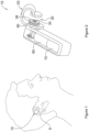
- an apparatus for monitoring blood pressure of a user is shown generally at 10, clipped to a portion of a user's ear 8.
- the apparatus 10 includes a clip 20 rotatably connected to a drive housing 50.
- the clip 20 is adapted to receive a portion of a user's ear 8 within a gap 30.
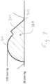
- a magnetic field sensor 34 mounted to an adjustable pressure pad 36 measures an arterial pulsatile waveform, as illustrated at 300 in Figure 7 of blood flow within the ear 8 and sends the waveform measurements to a processor 70 within the drive housing 50, by means as are commonly known.
- a motor 60 within the drive housing 50 is operably connected to the adjustable pressure pad 36 and periodically extends and retracts the adjustable pressure pad 36 to calibrate the waveform measurements, as will be set out in more detail below.
- the present embodiment of the invention is illustrated clipped to an ear 8, it will be appreciated that the invention may be adapted to clip to other parts of a user's body, such as, by way of non-limiting example, a finger.
- the clip 20 includes first and second side members, 22 and 24, respectively, joined with a generally u-shaped base 26 forming the gap 30 therebetween.
- the gap 30 is adapted to receive a portion of a user's ear 8 therein.
- the clip 20 is formed to accommodate varying sizes of connective tissue arch and the top of the ear cartilage of different users, as is commonly known.
- the clip 20 is formed with a rigid, non-ferrous material, so as to retain its shape when forces are applied thereto and to not vary the magnetic field at the magnetic field sensor 34.
- the first side member 22 includes a circular bore 28 on an axis 150 therethrough.
- the clip 20 is rotatably coupled to the drive housing 50 through the circular bore 28, as will be set out below.
- the clip 20 includes a magnet 32 on the second side member 24, centred on the axis 150. As illustrated in Figure 5 , the magnet 32 may be retained within the second side member 24.
- the magnet 32 may be a rare earth magnet, such as, by way of non-limiting example, neodymium and samarium-cobalt magnets, as are commonly known, although other types of magnets may be useful as well.
- the magnetic field sensor 34 may be mounted within the adjustable pressure pad 36, as illustrated in Figure 5 , centered on the axis 150.
- the magnetic field sensor 34 may be a Hall effect sensor. As is commonly known, a Hall effect sensor requires an electric current for operation.
- a battery 72 is included in the drive housing 50.
- the magnetic field sensor 34 is connected to both the battery 72 and the processor 70 by means as are commonly known. Note that, for clarity, wiring is not shown on Figures 3-5 .
- the magnet 32 provides a magnetic field for the magnetic field sensor 34 such that the magnetic field sensor 34 detects the interruption of the magnetic field by the blood flow of the user in the ear 8 therebetween.
- the amount of deflection within the clip 20 in response to an applied force may be known such that the change in width of the gap 30 is known in response to such force such that the effect on the measurements taken by the magnetic field sensor by a known amount.
- magnetic field sensors are able to accurately measure distance to the magnetic source. Therefore, in operation, the clip 20 is located around the ear of the user such that the distance between the magnetic field sensor and the magnet 32 will vary in response to the blood flow through that portion of the ear. In particular, each pulse will cause the distance therebetween to increase. This distance is thereby measured and plotted to produce the arterial pulsate waveform as illustrated in Figure 7 .
- the clip 20 may incorporate strain meters as are commonly known to measure the amount of deflection and therefore the change in the gap 30.
- the drive housing 50 is generally formed in a rounded rectangular box shape with an inside cavity 62 and has inner and outer surfaces 64 and 66, respectively.
- the drive housing 50 extends between top and bottom edges, 52 and 54, respectively, and between first and second sides, 56 and 58, respectively. It will be appreciated that the drive housing 50 may include front and back covers (not shown) to enclose the inside cavity 62 and protect the contents therein.
- a cylindrical clip shaft portion 80 extends from the second side 58 of the drive housing 50 proximate to the top edge 52 along the axis 150 to a cylinder edge 82.
- the clip shaft portion 80 is adapted to rotatably receive the clip 20 thereon through the bore 28.
- a collar 86 is adapted to be received on the clip shaft portion 80 proximate to the cylinder edge 82 to retain the clip 20 on the clip shaft portion 80, as is commonly known. It will be appreciated that other retaining methods may be used to retain the clip 20 on the clip shaft portion 80, such as, by way of non-limiting example, a groove and retaining ring, a threaded collar, or adhesive.
- the clip 20 may be rotated about the axis 150 to adapt the apparatus 10 for varying ear sizes and shapes.
- the clip shaft portion 80 includes a hexagonal bore 84 therethrough between the cylinder edge 82 and the inner surface 64 along the axis 150 adapted to receive a hexagonal extension nut 90 therein, as best illustrated in Figures 2- 4.
- the bore 84 and extension nut 90 are illustrated as hexagonal in the current embodiment of the invention, it will be appreciated that other non-circular shapes may be useful, as well, such as, by way of non-limiting example, pentagonal or octagonal, such that the extension nut 90 does not rotate about the axis 150 within the bore 84.
- the extension nut extends between first and second ends, 96 and 98, respectively and includes internal threading 92 along the axis 150 adapted to engage with external threading 94 on a threaded driveshaft 100.
- the threaded driveshaft 100 is operably connected to the motor 60 through a pair of bevel gears 102 and a motor driveshaft 104, as is commonly known.
- the gears 102 and driveshafts 100 and 104 are formed with non-ferrous materials so that they do not interfere with the magnetic field sensor 34.
- the adjustable pressure pad 36 is secured to the second end 98 of the extension nut 90.
- the motor 60 is operably connected to the adjustable pressure pad 36 and periodically extends and retracts the adjustable pressure pad 36 to calibrate the waveform measurements, as will be set out below.
- the motor 60 rotates the motor driveshaft 104 thereby rotating the threaded driveshaft 100 via the gears 102.
- the engaged threading 92 and 94 extends the extension nut 90 from a retracted first position, as illustrated in Figure 3 , with a retracted separation distance 110 between the adjustable pressure pad 36 and the second side member 24, to an extended second position, as illustrated in Figure 4 , with an extended separation distance 110 between the adjustable pressure pad 36 and the second side member 24.
- the separation distance 110 is reduced when in the extended second position and is selected such that a predetermined force is applied to the ear 8 thereby producing a known blood pressure therethrough.
- the extension nut 90 and bore 84 are non-circular, the extension nut 90 is not free to rotate within the bore 84 and therefore extends along the axis 150, as is commonly known.
- the apparatus 10 includes a control system 200.
- the processor 70 illustrated previously in Figures 2 through 5 , comprises a processing circuit 220 and memory 222 that stores machine instructions that, when executed by the processing circuit 220, cause the processing circuit 220 to perform one or more of the operations and methods described herein.
- the processing circuit 220 may optionally contain a cache memory unit for temporary storage of instructions, data, or computer addresses.
- the control system 200 further includes a data storage 226 of any conventional type operable to store a plurality of entries containing the waveform measurements received from the magnetic field sensor 34.
- the processing circuit 220 may contain instructions to convert the waveform measurements to blood pressure data, or the raw data received from the magnetic field sensor 34 may be stored within the data storage 226 and processed further into blood pressure data with a remote processor. Power is supplied to the magnetic field sensor 34 and processing circuit 220 with the motor 60 controlled by the processing circuit 220 to periodically extend and retract the adjustable pressure pad 36, as outline above.
- the control system 200 also includes an input/output interface 224 such as a radio transmitter, ethernet adapter, USB connection or the like for providing communication between the processing circuit 220 and external systems.
- processing circuit is intended to broadly encompass any type of device or combination of devices capable of performing the functions described herein, including (without limitation) other types of microprocessing circuits, microcontrollers, other integrated circuits, other types of circuits or combinations of circuits, logic gates or gate arrays, or programmable devices of any sort, for example, either alone or in combination with other such devices located at the same location or remotely from each other. Additional types of processing circuit(s) will be apparent to those ordinarily skilled in the art upon review of this specification, and substitution of any such other types of processing circuit(s) is considered not to depart from the scope of the present invention as defined by the claims appended hereto.
- the processing circuit 220 can be implemented as a single-chip, multiple chips and/or other electrical components including one or more integrated circuits and printed circuit boards.
- Computer code comprising instructions for the processing circuit(s) 220 to carry out the various embodiments, aspects, features, etc. of the present disclosure may reside in the memory 222.
- the processing circuit 220 can be implemented as a single-chip, multiple chips and/or other electrical components including one or more integrated circuits and printed circuit boards.
- the processing circuit 220 together with a suitable operating system may operate to execute instructions in the form of computer code and produce and use data.
- the operating system may be Windows-based, Mac-based, or Unix or Linux-based, among other suitable operating systems. Operating systems are generally well known and will not be described in further detail here.
- Memory 222 may include various tangible, non-transitory computer-readable media including Read-Only Memory (ROM) and/or Random-Access Memory (RAM).
- ROM Read-Only Memory
- RAM Random-Access Memory
- ROM acts to transfer data and instructions unidirectionally to the processing circuit 220
- RAM is used typically to transfer data and instructions in a bi-directional manner.
- RAM includes computer program instructions that when executed by the processing circuit 220 cause the processing circuit 220 to execute the program instructions described in greater detail below.
- the term "memory” as used herein encompasses one or more storage mediums and generally provides a place to store computer code (e.g., software and/or firmware) and data that are used by the control system 200.
- Memory 222 may further include a floppy disk, CD-ROM, DVD, magnetic disk, memory chip, ASIC, FPGA, EEPROM, EPROM, flash memory, optical media, or any other suitable memory from which processing circuit 220 can read instructions in computer programming languages.
- the data storage 226 stores information for a plurality of waveform measurements from the magnetic field sensor 34. These measurements are periodically calibrated by activating the motor 60 to extend the adjustable pressure pad 36 for a set period of time such that a known pressure is applied to the portion of the ear 8 located between the adjustable pressure pad 36 and the second side member 24 of the clip 20 with the adjustable pressure pad 36 in the extended position, as illustrated in Figure 4 . As the pressure applied is known, and the resulting effect to the blood flow through the ear is known, the measurements may be calibrated to match a known pressure as applied by the motor 60. Once calibrated, the motor 60 is activated again to retract the adjustable pressure pad 36, returning the apparatus 10 to the retracted position, as illustrated in Figure 3 . It will be appreciated that the calibration of the measured arterial pulsatile waveform may be accomplished in many ways including arithmetic, geometric, modelled and spectal methods.
- the arterial pulsatile waveform 300 may be recorded as set out above and illustrated in Figure 7 which includes a diastolic 302 and systolic pressure 306.
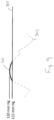
- Figure 8 when the motor 60 is activated to apply a known pressure 304 as determined by the movement distance of the pressure pad 36.
- the applied pressure is above the diastolic pressure 302 of the arterial pulsatile waveform 300 the measured diastolic pressure will no longer be recorded in arterial pulsatile waveform 300 and this diastolic pressure can therefore be adjusted to the applied pressure at that point.
- area (generally indicated at 308 ) under the arterial pulsatile waveform 300 may be measured to determine the volume of blood flow through the artery according to known methods.
- the apparatus 10 may be combined with one or more other sensors for use in monitoring the status of a patient including, breathing rate, oxygen saturation, activity level, temperature and whether the patient is awake or sleeping.
- additional sensors may include without limitation, oximeters, tricolor LED/phototransistors, accelerometers, microphones, nasal thermistors, thermometers, skin galvanometers, linear photo transistor arrays, ultrasonic probes and arrays, infra-red LED/phototransistor pairs, RF impedance plethysmography and piezoelectric vibration elements.
- the ear does not include any muscle therein. Additionally, the ear is not located at an extremity of the body which is significantly subjected to movement as is a hand or foot. Therefore, the measurements obtained from such location will not be dependent upon the movement and activity of the user. It will be appreciated that as the distance between the pad 36 and the magnetic field sensor 34 is known the volume of tissue between these surfaces is also known with a high degree of accuracy. Such accurate measurements of tissue volume may be useful for other purposes such as, by way of non-limiting example, measuring body fat percentages or water content.
Landscapes
- Health & Medical Sciences (AREA)
- Life Sciences & Earth Sciences (AREA)
- Physics & Mathematics (AREA)
- Engineering & Computer Science (AREA)
- Animal Behavior & Ethology (AREA)
- Veterinary Medicine (AREA)
- Biophysics (AREA)
- Pathology (AREA)
- Public Health (AREA)
- Biomedical Technology (AREA)
- Heart & Thoracic Surgery (AREA)
- Medical Informatics (AREA)
- Molecular Biology (AREA)
- Surgery (AREA)
- General Health & Medical Sciences (AREA)
- Cardiology (AREA)
- Vascular Medicine (AREA)
- Physiology (AREA)
- Otolaryngology (AREA)
- Ophthalmology & Optometry (AREA)
- Dentistry (AREA)
- Optics & Photonics (AREA)
- Electromagnetism (AREA)
- Hematology (AREA)
- Pulmonology (AREA)
- Oral & Maxillofacial Surgery (AREA)
- Human Computer Interaction (AREA)
- Nuclear Medicine, Radiotherapy & Molecular Imaging (AREA)
- Radiology & Medical Imaging (AREA)
- Measuring Pulse, Heart Rate, Blood Pressure Or Blood Flow (AREA)
Claims (15)
- Gerät zur Überwachung des Blutdrucks eines Benutzers, wobei das Gerät umfasst:einen Clip (20) mit einer Basis mit zwei Seitenelementen, die eingerichtet sind, um freigebbar einen Anteil eines Körpers des Benutzers dazwischen aufzunehmen;ein einstellbares Druckkissen (36), das an einem der zwei Seitenelemente montiert ist, die von dem anderen der zwei Seitenelemente durch einen Trennabstand getrennt sind;einen Magnetfeldsensor (34), der an einem der zwei Seitenelemente montiert ist;einen Magneten (32), der an dem anderen der zwei Seitenelemente gegenüber von dem Magnetfeldsensor montiert ist und um den Trennabstand beabstandet ist;einen Motor (60), der funktionell mit dem einstellbaren Druckkissen verbunden ist; undwobei der Trennabstand von dem Motor auswählbar einstellbar ist.
- Gerät nach Anspruch 1, wobei der Clip eine U-förmige Basis (26) mit zwei Seitenelementen hat, die sich von der U-förmigen Basis erstrecken und einen festen Abstand dazwischen definieren, wobei der Clip eingerichtet ist, um freigebbar einen Anteil eines Körpers des Benutzers dazwischen aufzunehmen.
- Gerät nach Anspruch 2, wobei der Clip aus einem starren Material gebildet ist, das den festen Abstand dazwischen beibehält, wenn Kräfte darauf angewendet werden.
- Gerät nach einem der Ansprüche 1 bis 3, wobei der Magnet direkt an dem anderen der zwei Seitenelemente gegenüber von dem Magnetfeldsensorm montiert ist.
- Gerät nach einem der Ansprüche 1 bis 4, wobei der Motor funktionell über eine mit Gewinde versehene Antriebswelle (100), ein Paar Zahnräder (102) und eine Motorantriebswelle (104) mit dem Druckkissen verbunden ist.
- Gerät nach einem der Ansprüche 1 bis 5, wobei der Clip so bemessen ist, dass er einen Anteil eines Ohrs des Benutzers aufnimmt.
- Gerät nach einem der Ansprüche 1 bis 5, wobei der Clip so bemessen ist, dass er einen Anteil eines Fingers des Benutzers aufnimmt.
- Gerät nach einem der Ansprüche 1 bis 5, wobei der Trennabstand periodisch durch den Motor reduziert wird, um Druck mit dem einstellbaren Druckkissen auf den Anteil des Körpers des Benutzers auszuüben, der sich zwischen dem einstellbaren Drucckissen und dem Magneten befindet.
- Gerät nach einem der Ansprüche 1 bis 5, wobei der Magnet einen Seltenerdmagneten umfasst.
- Gerät nach einem der Ansprüche 1 bis 5, wobei der Magnetfeldsensor einen Halleffektsensor umfasst.
- Gerät nach einem der Ansprüche 1 bis 5, wobei der Magnetfeldsensor eingerichtet ist, um eine arterielle pulsierende Wellenform des Blutflusses innerhalb des Anteils des Körpers des Benutzers zu messen, der sich zwischen dem einstellbaren Drucckissen und dem Magneten befindet.
- Gerät nach einem der Ansprüche 1 bis 5, des Weiteren umfassend einen Prozessor in Kommunikation mit dem Magnetfeldsensor und dem Motor.
- Gerät nach Anspruch 12, wobei der Prozessor Daten von dem Magnetfeldsensor überwacht und aufzeichnet.
- Gerät nach Anspruch 13, wobei der Prozessor ausgestaltet ist, um zu bewirken, dass der Motor das einstellbare Druckkissen antreibt, um den Trennabstand periodisch zu reduzieren und einen Druck mit dem einstellbaren Druckkissen auf den Anteil des Körpers des Benutzers auszuüben, der sich zwischen dem einstellbaren Druckkissen und dem Magneten befindet.
- Gerät nach Anspruch 14, wobei der Prozessor ausgestaltet ist, um die Daten von dem Magnetfeldsensor relativ zu dem Druck zu kalibrieren.
Applications Claiming Priority (2)
| Application Number | Priority Date | Filing Date | Title |
|---|---|---|---|
| US16/197,192 US11357412B2 (en) | 2018-11-20 | 2018-11-20 | Wearable cardiovascular monitoring device |
| PCT/IB2019/059941 WO2020104945A1 (en) | 2018-11-20 | 2019-11-19 | Wearable cardiovascular monitoring device |
Publications (3)
| Publication Number | Publication Date |
|---|---|
| EP3866679A1 EP3866679A1 (de) | 2021-08-25 |
| EP3866679A4 EP3866679A4 (de) | 2022-08-03 |
| EP3866679B1 true EP3866679B1 (de) | 2023-08-30 |
Family
ID=70728508
Family Applications (1)
| Application Number | Title | Priority Date | Filing Date |
|---|---|---|---|
| EP19886341.7A Active EP3866679B1 (de) | 2018-11-20 | 2019-11-19 | Am körper tragbare kardiovaskuläre überwachungsvorrichtung |
Country Status (5)
| Country | Link |
|---|---|
| US (1) | US11357412B2 (de) |
| EP (1) | EP3866679B1 (de) |
| AU (1) | AU2019383580B2 (de) |
| IL (1) | IL283135B2 (de) |
| WO (1) | WO2020104945A1 (de) |
Families Citing this family (1)
| Publication number | Priority date | Publication date | Assignee | Title |
|---|---|---|---|---|
| IL296541A (en) * | 2020-03-18 | 2022-11-01 | 42Health Sensor Holdings Ltd | A multi-sensor biometric information monitoring device |
Family Cites Families (49)
| Publication number | Priority date | Publication date | Assignee | Title |
|---|---|---|---|---|
| US3412729A (en) | 1965-08-30 | 1968-11-26 | Nasa Usa | Method and apparatus for continuously monitoring blood oxygenation, blood pressure, pulse rate and the pressure pulse curve utilizing an ear oximeter as transducer |
| DE3807672A1 (de) * | 1988-03-09 | 1989-09-21 | Vectron Ges Fuer Technologieen | Verfahren zum kontinuierlichen messen des blutdrucks am menschen und blutdruckmessgeraet zum durchfuehren des verfahrens |
| US5316008A (en) | 1990-04-06 | 1994-05-31 | Casio Computer Co., Ltd. | Measurement of electrocardiographic wave and sphygmus |
| JP3318727B2 (ja) | 1994-06-06 | 2002-08-26 | 日本光電工業株式会社 | 脈波伝播時間方式血圧計 |
| WO1996039927A1 (en) | 1995-06-07 | 1996-12-19 | Blackbox, Inc. | Method for noninvasive intermittent and/or continuous hemoglobin, arterial oxygen content, and hematocrit determination |
| US5865755A (en) | 1996-10-11 | 1999-02-02 | Dxtek, Inc. | Method and apparatus for non-invasive, cuffless, continuous blood pressure determination |
| US6198394B1 (en) | 1996-12-05 | 2001-03-06 | Stephen C. Jacobsen | System for remote monitoring of personnel |
| US7097618B1 (en) | 2003-03-12 | 2006-08-29 | Transoma Medical, Inc. | Devices and methods for detecting and treating inadequate tissue perfusion |
| IL124787A0 (en) * | 1998-06-07 | 1999-01-26 | Itamar Medical C M 1997 Ltd | Pressure applicator devices particularly useful for non-invasive detection of medical conditions |
| US7621887B2 (en) | 2000-10-10 | 2009-11-24 | Meridian Medical Technologies, Inc. | Wet/dry automatic injector assembly |
| US6556852B1 (en) | 2001-03-27 | 2003-04-29 | I-Medik, Inc. | Earpiece with sensors to measure/monitor multiple physiological variables |
| GB0110313D0 (en) * | 2001-04-27 | 2001-06-20 | Hall Effect Technologies Ltd | Apparatus and method for analysing a fluid |
| US20030083559A1 (en) | 2001-10-31 | 2003-05-01 | Thompson David L. | Non-contact monitor |
| US20040249299A1 (en) | 2003-06-06 | 2004-12-09 | Cobb Jeffrey Lane | Methods and systems for analysis of physiological signals |
| WO2005034742A1 (ja) | 2003-10-09 | 2005-04-21 | Nippon Telegraph And Telephone Corporation | 生体情報検出装置及び血圧計 |
| CA2567769A1 (en) | 2004-05-10 | 2005-11-24 | Transoma Medical, Inc. | Portable device for monitoring electrocardiographic signals and indices of blood flow |
| JP4005095B2 (ja) * | 2004-07-27 | 2007-11-07 | 株式会社タニタ | 体組成計 |
| JP4460414B2 (ja) | 2004-10-06 | 2010-05-12 | 日本電信電話株式会社 | 血圧計 |
| CN100496389C (zh) | 2004-10-06 | 2009-06-10 | 日本电信电话株式会社 | 血压计 |
| JP2009505766A (ja) | 2005-08-31 | 2009-02-12 | コーニンクレッカ フィリップス エレクトロニクス エヌ ヴィ | 失神イベントの検出及び予測を行うシステム及び方法 |
| US20070070800A1 (en) | 2005-09-27 | 2007-03-29 | Nathalie Virag | Externally worn vasovagal syncope detection device |
| US8160682B2 (en) | 2006-02-06 | 2012-04-17 | The Board Of Trustees Of The Leland Stanford Junior University | Non-invasive cardiac monitor and methods of using continuously recorded cardiac data |
| US8073518B2 (en) | 2006-05-02 | 2011-12-06 | Nellcor Puritan Bennett Llc | Clip-style medical sensor and technique for using the same |
| US7539532B2 (en) | 2006-05-12 | 2009-05-26 | Bao Tran | Cuffless blood pressure monitoring appliance |
| US8968195B2 (en) | 2006-05-12 | 2015-03-03 | Bao Tran | Health monitoring appliance |
| KR100849383B1 (ko) | 2006-09-01 | 2008-07-31 | 상지대학교산학협력단 | 홀소자를 이용한 맥진 센서 |
| JP5228305B2 (ja) | 2006-09-08 | 2013-07-03 | ソニー株式会社 | 表示装置、表示方法 |
| US9196770B2 (en) | 2007-03-27 | 2015-11-24 | Newdoll Enterprises Llc | Pole-mounted power generation systems, structures and processes |
| WO2009032074A1 (en) * | 2007-08-28 | 2009-03-12 | Woolsthorpe, Llc | Integrated physiological sensor apparatus and system |
| US8116841B2 (en) | 2007-09-14 | 2012-02-14 | Corventis, Inc. | Adherent device with multiple physiological sensors |
| WO2009147597A1 (en) | 2008-06-02 | 2009-12-10 | Koninklijke Philips Electronics N.V. | Detection of impending syncope of a patient |
| US8588880B2 (en) * | 2009-02-16 | 2013-11-19 | Masimo Corporation | Ear sensor |
| US20100228103A1 (en) | 2009-03-05 | 2010-09-09 | Pacesetter, Inc. | Multifaceted implantable syncope monitor - mism |
| US8909330B2 (en) | 2009-05-20 | 2014-12-09 | Sotera Wireless, Inc. | Body-worn device and associated system for alarms/alerts based on vital signs and motion |
| US20110066042A1 (en) | 2009-09-15 | 2011-03-17 | Texas Instruments Incorporated | Estimation of blood flow and hemodynamic parameters from a single chest-worn sensor, and other circuits, devices and processes |
| BR112012017166A2 (pt) | 2009-12-23 | 2016-03-15 | Delta Dansk Elektronik Lys Og Akustik | dispositivo de monitoração |
| US8096186B2 (en) * | 2010-03-24 | 2012-01-17 | Carefusion 303, Inc. | Systems and methods for measuring fluid pressure within a disposable IV set connected to a fluid supply pump |
| US8560046B2 (en) | 2010-05-12 | 2013-10-15 | Irhythm Technologies, Inc. | Device features and design elements for long-term adhesion |
| EP2585958A1 (de) | 2010-06-24 | 2013-05-01 | Koninklijke Philips Electronics N.V. | Verfahren und vorrichtung für den nachweis eines kritischen hämodynamischen ereignisses bei einem patient |
| US8738121B2 (en) | 2010-08-23 | 2014-05-27 | Medtronic, Inc. | Method and apparatus for distinguishing epileptic seizure and neurocardiogenic syncope |
| SG192836A1 (en) | 2011-02-18 | 2013-09-30 | Sotera Wireless Inc | Modular wrist-worn processor for patient monitoring |
| US10588521B2 (en) * | 2013-07-10 | 2020-03-17 | Hitachi, Ltd. | Sphygmomanometer system |
| JPWO2015115114A1 (ja) | 2014-02-03 | 2017-03-23 | 日本電気株式会社 | 血圧測定システムおよび脈波センサ |
| WO2015193917A2 (en) | 2014-06-20 | 2015-12-23 | Healthcare Technology Innovation Centre | Method and system for cuff-less blood pressure (bp) measurement of a subject |
| CN104127176A (zh) | 2014-06-26 | 2014-11-05 | 北京信息科技大学 | 一种无充气泵结构的便携式血压脉搏测量仪 |
| US10338029B2 (en) * | 2014-12-10 | 2019-07-02 | General Electric Company | Systems and methods for improved physiological monitoring |
| CN105708431B (zh) | 2016-04-13 | 2019-04-02 | 清华大学 | 血压实时测量装置及测量方法 |
| US20180085057A1 (en) * | 2016-07-12 | 2018-03-29 | Innovaura Corporation | Health monitor system, sensor, and method |
| US10531797B2 (en) | 2016-09-19 | 2020-01-14 | International Business Machines Corporation | Wearable blood pressure monitoring system |
-
2018
- 2018-11-20 US US16/197,192 patent/US11357412B2/en active Active
-
2019
- 2019-11-19 IL IL283135A patent/IL283135B2/en unknown
- 2019-11-19 AU AU2019383580A patent/AU2019383580B2/en active Active
- 2019-11-19 EP EP19886341.7A patent/EP3866679B1/de active Active
- 2019-11-19 WO PCT/IB2019/059941 patent/WO2020104945A1/en not_active Ceased
Also Published As
| Publication number | Publication date |
|---|---|
| IL283135A (en) | 2021-06-30 |
| EP3866679A4 (de) | 2022-08-03 |
| EP3866679A1 (de) | 2021-08-25 |
| US20200155017A1 (en) | 2020-05-21 |
| WO2020104945A1 (en) | 2020-05-28 |
| US11357412B2 (en) | 2022-06-14 |
| AU2019383580B2 (en) | 2022-10-27 |
| IL283135B1 (en) | 2024-02-01 |
| AU2019383580A1 (en) | 2021-07-15 |
| IL283135B2 (en) | 2024-06-01 |
Similar Documents
| Publication | Publication Date | Title |
|---|---|---|
| US10631739B2 (en) | Monitoring vital signs | |
| US9585602B1 (en) | Obtaining medical diagnostic measurements | |
| JP2021530265A5 (de) | ||
| CN103645625B (zh) | 具有脉搏和血压检测功能的按摩手表及其使用方法 | |
| US20190021612A1 (en) | Wrist sphygmomanometer | |
| US20100069735A1 (en) | Device for mobile electrocardiogram recording | |
| CN109984736A (zh) | 一种血压测量装置及血压测量方法 | |
| US20120304784A1 (en) | Home uterine activity monitoring | |
| CN201767961U (zh) | 一种腕带式血压计 | |
| AU2019383580B2 (en) | Wearable cardiovascular monitoring device | |
| WO2010069248A1 (en) | Rfid medical devices and systems for reading physiological parameter | |
| CN103932685B (zh) | 用于检测人体节律振动的传感器 | |
| HK40061017A (en) | Wearable cardiovascular monitoring device | |
| HK40061017B (en) | Wearable cardiovascular monitoring device | |
| TWM582374U (zh) | Vibration sensing device, portable continuous blood pressure measuring device and portable heart Lung efficiency monitoring device | |
| CN203815439U (zh) | 一种用于检测人体节律振动的传感器 | |
| CN204698542U (zh) | 提高测量准确度的动态血压监测系统 | |
| US12207945B2 (en) | Wearable cardiovascular monitoring device | |
| CN201617819U (zh) | 一种动态血压仪袖带 | |
| CN208524862U (zh) | 一种心率带的传感器可拆卸结构 | |
| CN108882879A (zh) | 一种动脉搏动信号测量设备及其压力传感器 | |
| CN111388127A (zh) | 一种带力量控制的牙周探针 | |
| CN213551753U (zh) | 一种便于组合式跛行距离评估电子环 | |
| CN211066584U (zh) | 一种基于物联网的床旁血压计 | |
| CN101647697A (zh) | 基础体温数码测量仪 |
Legal Events
| Date | Code | Title | Description |
|---|---|---|---|
| STAA | Information on the status of an ep patent application or granted ep patent |
Free format text: STATUS: THE INTERNATIONAL PUBLICATION HAS BEEN MADE |
|
| PUAI | Public reference made under article 153(3) epc to a published international application that has entered the european phase |
Free format text: ORIGINAL CODE: 0009012 |
|
| STAA | Information on the status of an ep patent application or granted ep patent |
Free format text: STATUS: REQUEST FOR EXAMINATION WAS MADE |
|
| 17P | Request for examination filed |
Effective date: 20210518 |
|
| AK | Designated contracting states |
Kind code of ref document: A1 Designated state(s): AL AT BE BG CH CY CZ DE DK EE ES FI FR GB GR HR HU IE IS IT LI LT LU LV MC MK MT NL NO PL PT RO RS SE SI SK SM TR |
|
| DAV | Request for validation of the european patent (deleted) | ||
| DAX | Request for extension of the european patent (deleted) | ||
| REG | Reference to a national code |
Ref country code: HK Ref legal event code: DE Ref document number: 40061017 Country of ref document: HK |
|
| A4 | Supplementary search report drawn up and despatched |
Effective date: 20220701 |
|
| RIC1 | Information provided on ipc code assigned before grant |
Ipc: A61B 5/022 20060101ALI20220627BHEP Ipc: A61B 5/021 20060101AFI20220627BHEP |
|
| GRAP | Despatch of communication of intention to grant a patent |
Free format text: ORIGINAL CODE: EPIDOSNIGR1 |
|
| STAA | Information on the status of an ep patent application or granted ep patent |
Free format text: STATUS: GRANT OF PATENT IS INTENDED |
|
| INTG | Intention to grant announced |
Effective date: 20230406 |
|
| GRAS | Grant fee paid |
Free format text: ORIGINAL CODE: EPIDOSNIGR3 |
|
| GRAA | (expected) grant |
Free format text: ORIGINAL CODE: 0009210 |
|
| STAA | Information on the status of an ep patent application or granted ep patent |
Free format text: STATUS: THE PATENT HAS BEEN GRANTED |
|
| AK | Designated contracting states |
Kind code of ref document: B1 Designated state(s): AL AT BE BG CH CY CZ DE DK EE ES FI FR GB GR HR HU IE IS IT LI LT LU LV MC MK MT NL NO PL PT RO RS SE SI SK SM TR |
|
| REG | Reference to a national code |
Ref country code: GB Ref legal event code: FG4D |
|
| REG | Reference to a national code |
Ref country code: CH Ref legal event code: EP |
|
| REG | Reference to a national code |
Ref country code: DE Ref legal event code: R096 Ref document number: 602019036474 Country of ref document: DE |
|
| REG | Reference to a national code |
Ref country code: IE Ref legal event code: FG4D |
|
| P01 | Opt-out of the competence of the unified patent court (upc) registered |
Effective date: 20230831 |
|
| REG | Reference to a national code |
Ref country code: NL Ref legal event code: FP |
|
| REG | Reference to a national code |
Ref country code: LT Ref legal event code: MG9D |
|
| REG | Reference to a national code |
Ref country code: AT Ref legal event code: MK05 Ref document number: 1604324 Country of ref document: AT Kind code of ref document: T Effective date: 20230830 |
|
| PG25 | Lapsed in a contracting state [announced via postgrant information from national office to epo] |
Ref country code: GR Free format text: LAPSE BECAUSE OF FAILURE TO SUBMIT A TRANSLATION OF THE DESCRIPTION OR TO PAY THE FEE WITHIN THE PRESCRIBED TIME-LIMIT Effective date: 20231201 |
|
| PG25 | Lapsed in a contracting state [announced via postgrant information from national office to epo] |
Ref country code: IS Free format text: LAPSE BECAUSE OF FAILURE TO SUBMIT A TRANSLATION OF THE DESCRIPTION OR TO PAY THE FEE WITHIN THE PRESCRIBED TIME-LIMIT Effective date: 20231230 |
|
| PG25 | Lapsed in a contracting state [announced via postgrant information from national office to epo] |
Ref country code: SE Free format text: LAPSE BECAUSE OF FAILURE TO SUBMIT A TRANSLATION OF THE DESCRIPTION OR TO PAY THE FEE WITHIN THE PRESCRIBED TIME-LIMIT Effective date: 20230830 Ref country code: RS Free format text: LAPSE BECAUSE OF FAILURE TO SUBMIT A TRANSLATION OF THE DESCRIPTION OR TO PAY THE FEE WITHIN THE PRESCRIBED TIME-LIMIT Effective date: 20230830 Ref country code: NO Free format text: LAPSE BECAUSE OF FAILURE TO SUBMIT A TRANSLATION OF THE DESCRIPTION OR TO PAY THE FEE WITHIN THE PRESCRIBED TIME-LIMIT Effective date: 20231130 Ref country code: LV Free format text: LAPSE BECAUSE OF FAILURE TO SUBMIT A TRANSLATION OF THE DESCRIPTION OR TO PAY THE FEE WITHIN THE PRESCRIBED TIME-LIMIT Effective date: 20230830 Ref country code: LT Free format text: LAPSE BECAUSE OF FAILURE TO SUBMIT A TRANSLATION OF THE DESCRIPTION OR TO PAY THE FEE WITHIN THE PRESCRIBED TIME-LIMIT Effective date: 20230830 Ref country code: IS Free format text: LAPSE BECAUSE OF FAILURE TO SUBMIT A TRANSLATION OF THE DESCRIPTION OR TO PAY THE FEE WITHIN THE PRESCRIBED TIME-LIMIT Effective date: 20231230 Ref country code: HR Free format text: LAPSE BECAUSE OF FAILURE TO SUBMIT A TRANSLATION OF THE DESCRIPTION OR TO PAY THE FEE WITHIN THE PRESCRIBED TIME-LIMIT Effective date: 20230830 Ref country code: GR Free format text: LAPSE BECAUSE OF FAILURE TO SUBMIT A TRANSLATION OF THE DESCRIPTION OR TO PAY THE FEE WITHIN THE PRESCRIBED TIME-LIMIT Effective date: 20231201 Ref country code: FI Free format text: LAPSE BECAUSE OF FAILURE TO SUBMIT A TRANSLATION OF THE DESCRIPTION OR TO PAY THE FEE WITHIN THE PRESCRIBED TIME-LIMIT Effective date: 20230830 Ref country code: AT Free format text: LAPSE BECAUSE OF FAILURE TO SUBMIT A TRANSLATION OF THE DESCRIPTION OR TO PAY THE FEE WITHIN THE PRESCRIBED TIME-LIMIT Effective date: 20230830 |
|
| PG25 | Lapsed in a contracting state [announced via postgrant information from national office to epo] |
Ref country code: PL Free format text: LAPSE BECAUSE OF FAILURE TO SUBMIT A TRANSLATION OF THE DESCRIPTION OR TO PAY THE FEE WITHIN THE PRESCRIBED TIME-LIMIT Effective date: 20230830 |
|
| PG25 | Lapsed in a contracting state [announced via postgrant information from national office to epo] |
Ref country code: ES Free format text: LAPSE BECAUSE OF FAILURE TO SUBMIT A TRANSLATION OF THE DESCRIPTION OR TO PAY THE FEE WITHIN THE PRESCRIBED TIME-LIMIT Effective date: 20230830 |
|
| PG25 | Lapsed in a contracting state [announced via postgrant information from national office to epo] |
Ref country code: SM Free format text: LAPSE BECAUSE OF FAILURE TO SUBMIT A TRANSLATION OF THE DESCRIPTION OR TO PAY THE FEE WITHIN THE PRESCRIBED TIME-LIMIT Effective date: 20230830 Ref country code: RO Free format text: LAPSE BECAUSE OF FAILURE TO SUBMIT A TRANSLATION OF THE DESCRIPTION OR TO PAY THE FEE WITHIN THE PRESCRIBED TIME-LIMIT Effective date: 20230830 Ref country code: ES Free format text: LAPSE BECAUSE OF FAILURE TO SUBMIT A TRANSLATION OF THE DESCRIPTION OR TO PAY THE FEE WITHIN THE PRESCRIBED TIME-LIMIT Effective date: 20230830 Ref country code: EE Free format text: LAPSE BECAUSE OF FAILURE TO SUBMIT A TRANSLATION OF THE DESCRIPTION OR TO PAY THE FEE WITHIN THE PRESCRIBED TIME-LIMIT Effective date: 20230830 Ref country code: DK Free format text: LAPSE BECAUSE OF FAILURE TO SUBMIT A TRANSLATION OF THE DESCRIPTION OR TO PAY THE FEE WITHIN THE PRESCRIBED TIME-LIMIT Effective date: 20230830 Ref country code: CZ Free format text: LAPSE BECAUSE OF FAILURE TO SUBMIT A TRANSLATION OF THE DESCRIPTION OR TO PAY THE FEE WITHIN THE PRESCRIBED TIME-LIMIT Effective date: 20230830 Ref country code: SK Free format text: LAPSE BECAUSE OF FAILURE TO SUBMIT A TRANSLATION OF THE DESCRIPTION OR TO PAY THE FEE WITHIN THE PRESCRIBED TIME-LIMIT Effective date: 20230830 Ref country code: PT Free format text: LAPSE BECAUSE OF FAILURE TO SUBMIT A TRANSLATION OF THE DESCRIPTION OR TO PAY THE FEE WITHIN THE PRESCRIBED TIME-LIMIT Effective date: 20240102 |
|
| PG25 | Lapsed in a contracting state [announced via postgrant information from national office to epo] |
Ref country code: IT Free format text: LAPSE BECAUSE OF FAILURE TO SUBMIT A TRANSLATION OF THE DESCRIPTION OR TO PAY THE FEE WITHIN THE PRESCRIBED TIME-LIMIT Effective date: 20230830 |
|
| REG | Reference to a national code |
Ref country code: DE Ref legal event code: R097 Ref document number: 602019036474 Country of ref document: DE |
|
| REG | Reference to a national code |
Ref country code: CH Ref legal event code: PL |
|
| PG25 | Lapsed in a contracting state [announced via postgrant information from national office to epo] |
Ref country code: MC Free format text: LAPSE BECAUSE OF FAILURE TO SUBMIT A TRANSLATION OF THE DESCRIPTION OR TO PAY THE FEE WITHIN THE PRESCRIBED TIME-LIMIT Effective date: 20230830 |
|
| PLBE | No opposition filed within time limit |
Free format text: ORIGINAL CODE: 0009261 |
|
| STAA | Information on the status of an ep patent application or granted ep patent |
Free format text: STATUS: NO OPPOSITION FILED WITHIN TIME LIMIT |
|
| PG25 | Lapsed in a contracting state [announced via postgrant information from national office to epo] |
Ref country code: LU Free format text: LAPSE BECAUSE OF NON-PAYMENT OF DUE FEES Effective date: 20231119 |
|
| PG25 | Lapsed in a contracting state [announced via postgrant information from national office to epo] |
Ref country code: CH Free format text: LAPSE BECAUSE OF NON-PAYMENT OF DUE FEES Effective date: 20231130 |
|
| PG25 | Lapsed in a contracting state [announced via postgrant information from national office to epo] |
Ref country code: MC Free format text: LAPSE BECAUSE OF FAILURE TO SUBMIT A TRANSLATION OF THE DESCRIPTION OR TO PAY THE FEE WITHIN THE PRESCRIBED TIME-LIMIT Effective date: 20230830 Ref country code: LU Free format text: LAPSE BECAUSE OF NON-PAYMENT OF DUE FEES Effective date: 20231119 Ref country code: CH Free format text: LAPSE BECAUSE OF NON-PAYMENT OF DUE FEES Effective date: 20231130 Ref country code: SI Free format text: LAPSE BECAUSE OF FAILURE TO SUBMIT A TRANSLATION OF THE DESCRIPTION OR TO PAY THE FEE WITHIN THE PRESCRIBED TIME-LIMIT Effective date: 20230830 |
|
| REG | Reference to a national code |
Ref country code: BE Ref legal event code: MM Effective date: 20231130 |
|
| 26N | No opposition filed |
Effective date: 20240603 |
|
| REG | Reference to a national code |
Ref country code: IE Ref legal event code: MM4A |
|
| PG25 | Lapsed in a contracting state [announced via postgrant information from national office to epo] |
Ref country code: IE Free format text: LAPSE BECAUSE OF NON-PAYMENT OF DUE FEES Effective date: 20231119 |
|
| PG25 | Lapsed in a contracting state [announced via postgrant information from national office to epo] |
Ref country code: BE Free format text: LAPSE BECAUSE OF NON-PAYMENT OF DUE FEES Effective date: 20231130 |
|
| PG25 | Lapsed in a contracting state [announced via postgrant information from national office to epo] |
Ref country code: IE Free format text: LAPSE BECAUSE OF NON-PAYMENT OF DUE FEES Effective date: 20231119 Ref country code: BE Free format text: LAPSE BECAUSE OF NON-PAYMENT OF DUE FEES Effective date: 20231130 |
|
| PG25 | Lapsed in a contracting state [announced via postgrant information from national office to epo] |
Ref country code: BG Free format text: LAPSE BECAUSE OF FAILURE TO SUBMIT A TRANSLATION OF THE DESCRIPTION OR TO PAY THE FEE WITHIN THE PRESCRIBED TIME-LIMIT Effective date: 20230830 |
|
| PG25 | Lapsed in a contracting state [announced via postgrant information from national office to epo] |
Ref country code: BG Free format text: LAPSE BECAUSE OF FAILURE TO SUBMIT A TRANSLATION OF THE DESCRIPTION OR TO PAY THE FEE WITHIN THE PRESCRIBED TIME-LIMIT Effective date: 20230830 |
|
| PG25 | Lapsed in a contracting state [announced via postgrant information from national office to epo] |
Ref country code: CY Free format text: LAPSE BECAUSE OF FAILURE TO SUBMIT A TRANSLATION OF THE DESCRIPTION OR TO PAY THE FEE WITHIN THE PRESCRIBED TIME-LIMIT; INVALID AB INITIO Effective date: 20191119 |
|
| PG25 | Lapsed in a contracting state [announced via postgrant information from national office to epo] |
Ref country code: HU Free format text: LAPSE BECAUSE OF FAILURE TO SUBMIT A TRANSLATION OF THE DESCRIPTION OR TO PAY THE FEE WITHIN THE PRESCRIBED TIME-LIMIT; INVALID AB INITIO Effective date: 20191119 |
|
| PG25 | Lapsed in a contracting state [announced via postgrant information from national office to epo] |
Ref country code: TR Free format text: LAPSE BECAUSE OF FAILURE TO SUBMIT A TRANSLATION OF THE DESCRIPTION OR TO PAY THE FEE WITHIN THE PRESCRIBED TIME-LIMIT Effective date: 20230830 |
|
| PGFP | Annual fee paid to national office [announced via postgrant information from national office to epo] |
Ref country code: NL Payment date: 20251126 Year of fee payment: 7 |
|
| PGFP | Annual fee paid to national office [announced via postgrant information from national office to epo] |
Ref country code: DE Payment date: 20251119 Year of fee payment: 7 |
|
| PGFP | Annual fee paid to national office [announced via postgrant information from national office to epo] |
Ref country code: GB Payment date: 20251113 Year of fee payment: 7 |
|
| PGFP | Annual fee paid to national office [announced via postgrant information from national office to epo] |
Ref country code: FR Payment date: 20251124 Year of fee payment: 7 |