EP3866568A1 - Led-streifen - Google Patents
Led-streifen Download PDFInfo
- Publication number
- EP3866568A1 EP3866568A1 EP20215458.9A EP20215458A EP3866568A1 EP 3866568 A1 EP3866568 A1 EP 3866568A1 EP 20215458 A EP20215458 A EP 20215458A EP 3866568 A1 EP3866568 A1 EP 3866568A1
- Authority
- EP
- European Patent Office
- Prior art keywords
- led
- multichip
- island
- led strip
- strip according
- Prior art date
- Legal status (The legal status is an assumption and is not a legal conclusion. Google has not performed a legal analysis and makes no representation as to the accuracy of the status listed.)
- Granted
Links
Images

Classifications
-
- H—ELECTRICITY
- H05—ELECTRIC TECHNIQUES NOT OTHERWISE PROVIDED FOR
- H05B—ELECTRIC HEATING; ELECTRIC LIGHT SOURCES NOT OTHERWISE PROVIDED FOR; CIRCUIT ARRANGEMENTS FOR ELECTRIC LIGHT SOURCES, IN GENERAL
- H05B45/00—Circuit arrangements for operating light-emitting diodes [LED]
- H05B45/20—Controlling the colour of the light
-
- H—ELECTRICITY
- H05—ELECTRIC TECHNIQUES NOT OTHERWISE PROVIDED FOR
- H05B—ELECTRIC HEATING; ELECTRIC LIGHT SOURCES NOT OTHERWISE PROVIDED FOR; CIRCUIT ARRANGEMENTS FOR ELECTRIC LIGHT SOURCES, IN GENERAL
- H05B45/00—Circuit arrangements for operating light-emitting diodes [LED]
- H05B45/10—Controlling the intensity of the light
Definitions
- the invention relates to an LED strip with at least one LED island and with cables for connection to a voltage supply or to further LED islands.
- the LED strip is preferably provided as part of an escape route marking system. Escape route marking systems are prescribed in particular on board ships, aircraft or in public buildings (such as subway stations, hospitals, cinemas, congress centers, open-plan offices, airports).
- the LED strip is intended, in particular, to be used to mark escape routes on board ships, but can also be used advantageously elsewhere, for example on board aircraft or in buildings.
- LED strips for escape route marking strips are from the DE 196 27 856 A1 famous.
- the writing shows in the Fig. 3 , 4, 5 LED islands that are connected to one another by three conductors.
- Each LED island consists of a circuit board and an LED element as a light source.
- a resistor is assigned to each LED element. Due to the connection consisting of three conductors, the interconnection is relatively complex.
- the LED strip must have a certain number of LED islands per meter of length that are to be supplied with power. This results in a certain power consumption per meter of length.
- the power consumption is primarily dependent on the LEDs and resistors used in the LED islands.
- the light available is primarily from the LEDs used. The aim is for the lowest possible power consumption, low heat generation, high luminosity and a long service life for the LEDs.
- the object of the present invention is to create an LED strip with high efficiency, low power consumption, high luminous intensity, long service life and / or the lowest possible temperature.
- it can be the object of the invention to design connections of the LED islands in such a way that only a low contact resistance is possible and / or the cables to be connected need to be changed or processed as little as possible.
- the LED strip according to the invention has the features of claim 1.
- at least one multichip LED and at least one electrical resistor connected in series are provided on each LED island.
- a multichip LED is understood here to mean any LED element that has two or more LEDs as light sources. This means that the electrical resistance can be connected to several LEDs in a small space. The connection resistance of several LEDs is also higher than the connection resistance of just one LED.
- a multichip LED with several LEDs and correspondingly higher electrical power naturally generates a higher light intensity than a single LED.
- the multichip LED With the same light intensity and almost the same power in relation to a single LED, the multichip LED can be operated with lower current, so that as a side effect more meters of LED strips can be operated on one voltage source, which leads to a reduction in the voltage sources and less cabling during the Installation and thus leads to significant installation advantages and cost savings.
- the multi-chip LED ensures less heat generation per LED, which enables a longer service life.
- the LED islands are advantageously connected to one another via a two-wire system. This means that the cables provided for connection only have two conductors or wires.
- the LEDs used within the multichip LED are preferably connected in series with one another and with the resistor.
- the electrical consumers of an LED island are connected in parallel to the electrical consumers of the other LED islands of the same LED strip.
- the LED strip preferably extends over 20 to 50 m. Depending on the application, other lengths can also be provided, for example 2 to 20 m or 50 to 100 m or different.
- precisely one multichip LED and / or precisely one electrical resistor can be provided on the LED island. This enables simple assembly and a good controllability of the heat development.
- five or more LED islands can be connected to one another via multi-core cables within a length of 1 m.
- the LED islands are advantageously connected electrically in parallel with one another so that if one LED island fails, the others do not also fail.
- the cables are two-core.
- Infeed is understood here to be either an additional voltage supply or an additional electrical connection to an existing voltage supply.
- the additional connection is preferably connected to the existing voltage supply.
- both ends of the LED strip are connected to a common voltage supply. This can also apply to LED strips of other lengths. Due to the cross-section, only a limited amount of electricity can be supplied via the cables. The higher the power consumption of the LED islands, the more power has to be supplied and the more additional feeds have to be provided depending on the total length of the LED strip. Because of the multi-chip LED, low currents can be used. As a result, the number of additional feeds can be reduced depending on the length of the LED strip without having to increase the cross-section of the conductors in the cable.
- the multichip LED can have two or more LEDs, in particular three to five LEDs.
- the aim is to find a good compromise between costs, heat generation, power consumption and luminous efficacy, as well as service life.
- the multichip LED LEDs can have only one light color. Only light of one color is emitted, but with great brightness.
- the multichip LED emits exclusively or predominantly green light, preferably with an intensity maximum at a wavelength of 520 to 535 nm, in particular from 525 to 530 nm.
- the light is particularly bright and easily perceptible .
- the multichip LED emits exclusively or predominantly white light, preferably with a color temperature of 3000 to 5000 K.
- the white light has a color temperature of 4000 K.
- the color temperature which is 2700 K higher than that of warm white light, is perceived as brighter or the LEDs shine brighter.
- the white light is relatively neutral in the specified area.
- the LED island emits light with a light intensity of 300 to 1200 mcd, in particular with 500 to 800 mcd, preferably with 600 mcd.
- the stated luminous intensity relates to the entire LED island, regardless of the number of LEDs it contains.
- the LED island can have a lens-shaped cover over the multichip LED.
- the multichip LED is operated with 0.3 to 1.5 mA, in particular with 0.5 to 1.0 mA, preferably with 0.7 mA.
- the aim is a power consumption of around 3.5 mA per meter of LED strip and preferably with five LED islands per meter of LED strip.
- the multichip LED is operated with 0.5 to 20 percent of its rated current, in particular with 1 to 10 percent, preferably with 1.5 to 5 percent.
- a current of around 2.5 percent of the rated current or less is also advantageous.
- the nominal current here is either the nominal current or forward current specified by the supplier or manufacturer of the multichip LED, which is typically permissible for continuous operation, or a nominal current with which a service life of more than 100,000 at an ambient temperature T a of 45 ° C Hours is reached.
- the service life is usually assumed to be the time after which the multichip LED still has 70 percent of its initially existing luminous intensity, with a constant current over time.
- the multichip LED By controlling the multichip LED with a relatively low current, a drastic extension of the service life or a smaller decrease in the light intensity over time is possible. There is also less sensitivity to voltage peaks.
- the manufacturers of LEDs issue data sheets with characteristic curves on which the Luminous intensity or the luminous flux is shown in the manner of a characteristic curve as a function of the current consumption.
- the multichip LED should preferably be operated at the lower edge of its characteristic curve, for example with a current of 0.7 mA at a nominal current of 30 mA.
- the multichip LED is covered by a hat-shaped cover, the cover having a top side and outside the top side being at least partially surrounded by an encapsulation compound.
- the encapsulation compound fixes the cover on the board and preferably completely envelops the board.
- the cover advantageously rests on the board.
- the encapsulation compound also covers the connection contacts with the conductors and extends beyond an insulation of the cables.
- the top of the cover can be designed as part of a lens for a targeted light exit.
- an underside of the lens is planar and the upper side is convex or arched in a raised manner.
- other lens shapes can also be provided.
- an LED strip according to the invention can have the features of claim 13, either independently or in conjunction with at least one of the inventive aspects presented above.
- the LED island has a circuit board with connection contacts which are fork-shaped or slot-shaped.
- connection contacts which are fork-shaped or slot-shaped.
- contact elements are provided which are connected to a printed circuit board by crimping with wires and by riveting.
- the circuit board of the LED island is provided with fork-shaped or slot-shaped connection contacts and can thus accommodate conductors that are not kinked and are not crimped with additional contact elements.
- the board has slots which are either only formed in the surface of the board or completely break through the board perpendicular to the areal expansion of the board.
- the board advantageously has connection contacts for a cable connection, each with two conductors or wires, that is to say a total of four connection contacts.
- connection contacts are designed in such a way that the conductors of the cables can be connected to the circuit board in an alignment parallel to the surface of the circuit board.
- the ends of the conductors should not be bent over and inserted into holes. Rather, the conductors should be inserted into the connection contacts and soldered. Because of the length of the ladder and the Connection contacts, a 100 percent tailor-made coordination of the lengths is not required. Only a certain minimum length of each conductor needs to be connected to a minimum length of the associated connection contact, so that the transition resistance is as low as possible.
- the circuit board can have a longitudinal direction, a transverse direction and a thickness, the connection contacts being arranged on opposite end faces of the circuit board in the longitudinal direction and being aligned in the longitudinal direction.
- the connection contacts thus also run in the longitudinal direction of the LED strip.
- the subject of the invention is also an escape route marking system with an LED strip as specified in claim 16.
- the subject matter of the invention is also a method for operating an LED strip, as specified in claims 17 and 18.
- This is preferably an LED strip in an escape route marking system.
- the LED strip 10 shown consists of several LED islands 11 which are connected to one another via cables 12 and are connected to a common voltage supply 13.
- the individual LED islands 11 are electrically parallel to one another switched. Only four LED islands 11 are shown. In fact, significantly more LED islands 11 can be connected to the common voltage supply 13 to form a correspondingly longer LED strip.
- the cables 12 each have two conductors 14, 15 and can also be referred to as a two-wire system.
- the voltage supply 13 is preferably a constant voltage source.
- the length of the individual cables 12 is in particular dimensioned such that five LED islands 11 are arranged per meter of length of the LED strip 10. This results in the in Fig. 1 distances of 20 cm shown from the center of an LED island 11 to the center of the adjacent LED island 11. Alternatively, more LED islands 11 can be arranged per meter.
- Each LED island 11 has according to Fig. 3 a board 17 surrounded by an encapsulation compound 16.
- a multichip LED 18 and an electrical resistor 19 are held, in particular soldered, on the circuit board 17.
- the electrical resistance 19 is in Fig. 1 also referred to as R1.
- the multichip LED 18 has three LEDs 20 which are electrically connected in series with one another and with the resistor 19. In an exemplary embodiment not shown, four LEDs are provided for each multichip LED. Resistor 19 and power supply 13 must then be adapted accordingly.
- the encapsulation compound 16 encompasses the board 17 on all sides.
- the encapsulation compound 16 is only broken through by a hat-shaped cover 21 over the multichip LED 18 and by cables 12 fed in on two sides.
- the hat-shaped cover 21 rests with a lower circumferential edge 22 on the circuit board 17, in particular without touching the multichip LED 18.
- the lower edge 22 is provided with a radially outwardly directed collar 23 so that the encapsulation compound 16 securely holds the cover 21.
- the board 17 is rectangular with a longitudinal direction x, a transverse direction y and a thickness d.
- the plate 17 On the end faces 24, 25, the plate 17 has recesses 26 extending in the longitudinal direction on the outside, which pass through in the direction of the thickness d and are open to the outside in the longitudinal direction x.
- the end faces 24, 25 thereby have a fork-shaped appearance.
- the conductors 14, 15, which have been freed from insulation 27 at the ends, are inserted into the recesses 26 and soldered there.
- the end position of the conductors 14, 15 in the recesses 26 is shown in FIG Fig. 3 evident.
- Conductors 14, 15 and recesses 26 have a relatively large overlap in the longitudinal direction x, so that a relatively large area or a soldered connection running along two lines is possible.
- the resulting soldered connection is significantly more resilient than, for example, in the case of a conductor that is only connected to the circuit board 17 in a punctiform manner.
- Conductor tracks (not shown) run from the contact surfaces 28, 29 to the recesses 26, which are surrounded by electrically conductive edges 30. The edges 30 are soldered to the conductors 14, 15 and form connection contacts for the conductors 14, 15.
- the cover 21 is made of transparent plastic and is designed on the top in the manner of a lens 31.
- the lens 31 has a flat bottom 32 and a convex top 33.
- the multichip LED 18 and the resistor 19 are arranged spatially and thermally separated from one another. Only the multichip LED 18 is held under the cover 21, while the resistor 19 is provided outside the cover 21. A disadvantageous heat compensation from the resistor 19 to the multichip LED 18 is essentially only possible indirectly via the circuit board 17.
- the resistor 19 above the board 17 is also covered all around by the encapsulation compound 16, so that thermal radiation emanating from the resistor 19 is shielded.
- the electrical quantities of voltage supply 13, multichip LED 18 and resistor 19 are matched to one another in such a way that the multichip LED 18 is operated at the lower edge of its luminous intensity-current characteristic, preferably with 1 to 10 percent of the nominal current, in particular with about 2 .5 percent.
- the multichip LED 18 has in particular a luminous flux of 30 to 35 lumens with a nominal current of 30 mA.
- the multichip LED 18 is preferably operated with a continuous current of approximately 0.7 mA or less. With five LED islands 11 connected in parallel per meter of length of the LED strip 10, this results in a power requirement of 3.5 mA per meter.
- Each LED island 11 emits light with a light intensity of approximately 600 mcd.
Landscapes
- Illuminated Signs And Luminous Advertising (AREA)
- Led Device Packages (AREA)
Abstract
Description
- Die Erfindung betrifft einen LED-Streifen mit wenigstens einer LED-Insel und mit Kabeln zum Anschluss an eine Spannungsversorgung oder an weitere LED-Inseln. Vorzugsweise ist der LED-Streifen als Bestandteil eines Fluchtwegemarkierungssystems vorgesehen. Fluchtwegemarkierungssysteme sind insbesondere an Bord von Schiffen, von Flugzeugen oder in öffentlichen Gebäuden (wie beispielsweise U-Bahn-Stationen, Hospitäler, Kinos, Kongresscenter, Großraumbüros, Flughäfen) vorgeschrieben. Der LED-Streifen ist insbesondere zur Verwendung für die Markierung von Fluchtwegen an Bord von Schiffen vorgesehen, kann aber auch an anderer Stelle vorteilhaft genutzt werden, also beispielsweise an Bord von Flugzeugen oder in Gebäuden.
- LED-Streifen für Fluchtwegmarkierungsleisten sind aus der
DE 196 27 856 A1 bekannt. Die Schrift zeigt in denFig. 3 ,4, 5 LED-Inseln, die über drei Leiter miteinander verbunden sind. Jede LED-Insel besteht dort aus einer Leiterplatte und einem LED-Element als Leuchtmittel. Wie in Fig. 7 der Schrift gezeigt, ist jedem LED-Element ein Widerstand zugeordnet. Aufgrund der aus drei Leitern bestehenden Verbindung ist die Verschaltung relativ komplex. Für bestimmte Anwendungszwecke muss der LED-Streifen pro Meter Länge eine bestimmte Anzahl an LED-Inseln aufweisen, die mit Strom zu versorgen sind. Dadurch ergibt sich ein bestimmter Stromverbrauch pro Meter Länge. Der Stromverbrauch ist in erster Linie abhängig von den in die LED-Inseln eingesetzten LEDs und Widerständen. Das zur Verfügung stehende Licht ist in erster Linie von den verwendeten LEDs abhängig. Angestrebt werden ein möglichst geringer Stromverbrauch, eine geringe Wärmeentwicklung, eine hohe Lichtstärke und eine lange Lebensdauer der LEDs. - Aufgabe der vorliegenden Erfindung ist die Schaffung eines LED-Streifens mit hohem Wirkungsgrad, niedriger Stromaufnahme, hoher Lichtstärke, langer Lebensdauer und/oder möglichst niedriger Temperatur. Daneben kann es Aufgabe der Erfindung sein, Anschlüsse der LED-Inseln so auszubilden, dass ein nur geringer Übergangswiderstand möglich ist und/oder die anzuschließenden Kabel möglichst wenig verändert oder bearbeitet werden müssen.
- Zur Lösung der Aufgabe weist der erfindungsgemäße LED-Streifen die Merkmale des Anspruchs 1 auf. Insbesondere sind auf jeder LED-Insel mindestens eine Multichip-LED und mindestens ein elektrischer Widerstand in Reihe geschaltet vorgesehen. Als Multichip-LED wird hier jedes LED-Element verstanden, welches zwei oder mehr LEDs als Lichtquellen aufweist. Dadurch kann der elektrische Widerstand mit mehreren LEDs auf engem Raum verschaltet werden. Auch ist der Anschlusswiderstand mehrerer LEDs höher als der Anschlusswiderstand nur einer LED. Eine Multichip-LED mit mehreren LEDs und entsprechend höherer elektrischer Leistung erzeugt naturgemäß eine höhere Lichtstärke als eine einzelne LED. Bei gleicher Lichtstärke und nahezu gleicher Leistung im Verhältnis zu einer einzelnen LED kann die Multichip-LED mit geringerem Strom betrieben werden, sodass als Nebeneffekt mehr Meter LED-Streifen an einer Spannungsquelle betrieben werden können, was zu einer Reduzierung der Spannungsquellen, weniger Verkabelungsaufwand während der Installation und somit zu signifikanten Installationsvorteilen und Kosteneinsparungen führt. Zudem gewährleistet die Multichip-LED eine geringere Wärmeerzeugung pro LED, wodurch eine längere Lebensdauer möglich wird.
- Vorteilhafterweise sind die LED-Inseln über ein Zweileiter-System miteinander verbunden. Das heißt, die zur Verbindung vorgesehenen Kabel weisen nur zwei Leiter oder Adern auf. Die innerhalb der Multichip-LED verwendeten LEDs sind vorzugsweise miteinander und mit dem Widerstand in Reihe geschaltet. Die elektrischen Verbraucher einer LED-Insel sind parallel zu den elektrischen Verbrauchern der anderen LED-Inseln desselben LED-Streifens geschaltet.
- Vorzugsweise erstreckt sich der LED-Streifen über 20 bis 50 m. Je nach Anwendung können auch andere Längen vorgesehen sein, etwa 2 bis 20 m oder 50 bis 100 m oder davon abweichend.
- Nach einem weiteren Gedanken der Erfindung können auf der LED-Insel genau eine Multichip-LED und/oder genau ein elektrischer Widerstand vorgesehen sein. Dies ermöglicht eine einfache Montage und eine gute Beherrschbarkeit der Wärmeentwicklung.
- Nach einem weiteren Gedanken der Erfindung können innerhalb einer Länge von 1 m fünf oder mehr LED-Inseln über mehradrige Kabel miteinander verbunden sein. Die LED-Inseln sind vorteilhafterweise elektrisch zueinander parallel geschaltet, sodass bei Ausfall einer LED-Insel die anderen nicht auch ausfallen. Insbesondere sind die Kabel zweiadrig.
- Nach einem weiteren Gedanken der Erfindung kann vorgesehen sein, dass bei einer Gesamtlänge von 100 m nur ein zusätzlicher Anschluss für eine Einspeisung vorgesehen ist. Als Einspeisung wird hier entweder eine zusätzliche Spannungsversorgung oder eine zusätzliche elektrische Verbindung mit einer vorhandenen Spannungsversorgung verstanden. Vorzugsweise ist der zusätzliche Anschluss an die vorhandene Spannungsversorgung angeschlossen. Insbesondere sind beide Enden des LED-Streifens an eine gemeinsame Spannungsversorgung angeschlossen. Dies kann auch für LED-Streifen anderer Länge gelten. Über die Kabel kann aufgrund des Querschnitts nur eine begrenzte Menge Strom zugeführt werden. Je höher der Stromverbrauch der LED-Inseln ist, umso mehr Strom muss zugeführt werden und umso mehr zusätzliche Einspeisungen müssen in Abhängigkeit von der Gesamtlänge des LED-Streifens vorgesehen sein. Aufgrund der Multichip-LED kann mit niedrigen Strömen gearbeitet werden. Dadurch kann die Anzahl zusätzlicher Einspeisungen in Abhängigkeit von der Länge des LED-Streifens reduziert werden, ohne dass der Querschnitt der Leiter im Kabel vergrößert werden muss.
- Nach einem weiteren Gedanken der Erfindung kann die Multichip-LED zwei oder mehr LEDs aufweisen, insbesondere drei bis fünf LEDs. Angestrebt ist ein guter Kompromiss aus Kosten, Wärmeentwicklung, Stromaufnahme und Lichtausbeute sowie Lebensdauer.
- Nach einem weiteren Gedanken der Erfindung kann die Multichip-LED LEDs nur einer Lichtfarbe aufweisen. Es wird nur Licht einer Farbe, dafür aber mit großer Helligkeit abgestrahlt.
- Nach einem weiteren Gedanken der Erfindung kann vorgesehen sein, dass die Multichip-LED ausschließlich oder überwiegend grünes Licht abstrahlt, vorzugsweise mit einem Intensitätsmaximum bei einer Wellenlänge von 520 bis 535 nm, insbesondere von 525 bis 530 nm. Das Licht ist besonders hell und gut wahrnehmbar.
- Nach einem weiteren Gedanken der Erfindung kann vorgesehen sein, dass die Multichip-LED ausschließlich oder überwiegend weißes Licht abstrahlt, vorzugsweise mit einer Farbtemperatur von 3000 bis 5000 K. Insbesondere weist das weiße Licht eine Farbtemperatur von 4000 K auf. Die gegenüber warmweißem Licht von 2700 K höhere Farbtemperatur wird heller wahrgenommen bzw. die LEDs leuchten heller. Außerdem ist das weiße Licht in dem angegebenen Bereich relativ neutral.
- Nach einem weiteren Gedanken der Erfindung kann vorgesehen sein, dass die LED-Insel Licht mit einer Lichtstärke von 300 bis 1200 mcd abstrahlt, insbesondere mit 500 bis 800 mcd, vorzugsweise mit 600 mcd. Die genannte Lichtstärke ist auf die gesamte LED-Insel bezogen, unabhängig von der Anzahl der enthaltenen LEDs. Die LED-Insel kann dabei über der Multichip-LED eine linsenförmige Abdeckung aufweisen.
- Nach einem weiteren Gedanken der Erfindung kann vorgesehen sein, dass die Multichip-LED mit 0,3 bis 1,5 mA betrieben wird, insbesondere mit 0,5 bis 1,0 mA, vorzugsweise mit 0,7 mA. Angestrebt ist ein Stromverbrauch von etwa 3,5 mA pro Meter LED-Streifen und mit vorzugsweise fünf LED-Inseln pro Meter LED-Streifen.
- Nach einem weiteren Gedanken der Erfindung kann vorgesehen sein, dass die Multichip-LED mit 0,5 bis 20 Prozent ihres Nennstroms betrieben wird, insbesondere mit 1 bis 10 Prozent, vorzugsweise mit 1,5 bis 5 Prozent. Vorteilhaft ist auch ein Strom von etwa 2,5 Prozent des Nennstroms oder weniger. Als Nennstrom wird hier entweder der vom Anbieter bzw. Hersteller der Multichip-LED genannte Nennstrom oder Durchlassstrom verstanden, der typischerweise für einen Dauerbetrieb zulässig ist, oder aber ein Nennstrom, mit dem bei Umgebungstemperatur Ta von 45 °C eine Lebensdauer von mehr als 100.000 Stunden erreicht wird. Als Lebensdauer wird üblicherweise die Zeit angenommen, nach der die Multichip-LED noch 70 Prozent ihrer anfänglich vorhandenen Lichtstärke aufweist, bei im Zeitverlauf konstantem Strom. Durch die Ansteuerung der Multichip-LED mit relativ niedrigem Strom ist eine drastische Verlängerung der Lebensdauer oder ein im Zeitverlauf geringerer Abfall der Lichtstärke möglich. Auch besteht eine geringere Empfindlichkeit gegenüber Spannungsspitzen. Üblicherweise geben die Hersteller von LEDs Datenblätter mit Kennlinien heraus, auf denen die Lichtstärke oder der Lichtstrom nach Art einer Kennlinie in Abhängigkeit von der Stromaufnahme dargestellt ist. Die Multichip-LED soll hier vorzugsweise am unteren Rand ihrer Kennlinie betrieben werden, beispielsweise mit einem Strom von 0,7 mA bei einem Nennstrom von 30 mA.
- Nach einem weiteren Gedanken der Erfindung kann vorgesehen sein, dass die Multichip-LED von einer hutförmigen Abdeckung abgedeckt ist, wobei die Abdeckung eine Oberseite aufweist und außerhalb der Oberseite zumindest teilweise von einer Umspritzmasse umgeben ist. Die Umspritzmasse fixiert die Abdeckung auf der Platine und hüllt die Platine vorzugsweise komplett ein. Vorteilhafterweise liegt die Abdeckung auf der Platine auf. Die Umspritzmasse bedeckt insbesondere auch die Anschlusskontakte mit den Leitern und erstreckt sich bis über eine Isolierung der Kabel.
- Nach einem weiteren Gedanken der Erfindung kann die Oberseite der Abdeckung als Teil einer Linse für einen gezielten Lichtaustritt ausgebildet sein. Vorteilhafterweise ist eine Unterseite der Linse plan ausgebildet und die Oberseite konvex oder erhaben gewölbt. Je nach angestrebtem Lichtaustritt können auch andere Linsenformen vorgesehen sein.
- Ein erfindungsgemäßer LED-Streifen kann die Merkmale des Anspruchs 13 aufweisen, entweder unabhängig oder in Verbindung mit wenigstens einem der zuvor dargestellten erfinderischen Aspekte. Insbesondere weist die LED-Insel eine Platine mit Anschlusskontakten auf, welche gabelförmig oder schlitzförmig ausgebildet sind. Im Stand der Technik gemäß der
DE 196 27 856 A1 sind Kontaktelemente vorgesehen, die durch Crimpen mit Drähten und durch Nieten mit einer Leiterplatte verbunden sind. Im Gegensatz dazu ist bei der erfindungsgemäßen Ausgestaltung die Platine der LED-Insel mit gabelförmigen oder schlitzförmigen Anschlusskontakten versehen und kann so Leiter aufnehmen, die nicht abgeknickt und nicht mit zusätzlichen Kontaktelementen vercrimpt sind. Dadurch weist die Platine Schlitze auf, die entweder nur in der Oberfläche der Platine gebildet sind oder die Platine senkrecht zur flächenhaften Ausdehnung der Platine vollständig durchbrechen. Vorteilhafterweise weist die Platine Anschlusskontakte für eine Kabelverbindung mit je zwei Leitern oder Adern auf, also insgesamt vier Anschlusskontakte. - Die Anschlusskontakte sind so ausgebildet, dass die Leiter der Kabel in einer Ausrichtung parallel zur Oberfläche der Platine mit letzterer verbindbar sind. Enden der Leiter sollen nicht umgebogen und in Bohrungen eingesteckt sein. Vielmehr sollen die Leiter in die Anschlusskontakte eingelegt und verlötet werden. Aufgrund der Länge der Leiter und der Anschlusskontakte ist eine zu 100 Prozent passgenaue Abstimmung der Längen nicht erforderlich. Es muss nur eine bestimmte Mindestlänge eines jeden Leiters mit einer Mindestlänge des zugehörigen Anschlusskontakts verbunden sein, sodass ein möglichst geringer Übergangswiderstand besteht.
- Nach einem weiteren Gedanken der Erfindung kann die Platine eine Längsrichtung, eine Querrichtung und eine Dicke aufweisen, wobei die Anschlusskontakte an einander in Längsrichtung gegenüberliegenden Stirnseiten der Platine angeordnet und in Längsrichtung ausgerichtet sind. Die Anschlusskontakte verlaufen somit auch in Längsrichtung des LED-Streifens.
- Gegenstand der Erfindung ist auch ein Fluchtwegemarkierungssystem mit einem LED-Streifen, wie in Anspruch 16 angegeben.
- Gegenstand der Erfindung ist schließlich auch ein Verfahren zum Betrieb eines LED-Streifens, wie in Ansprüchen 17 und 18 angegeben. Dabei geht es vorzugsweise um einen LED-Streifen in einem Fluchtwegemarkierungssystem.
- Weitere Merkmale der Erfindung ergeben sich aus der Beschreibung im Übrigen und aus den Ansprüchen. Vorteilhafte Ausführungsbeispiele der Erfindung werden nachfolgend anhand von Zeichnungen näher erläutert. Es zeigen:
- Fig. 1
- ein elektrisches Schaltbild eines LED-Streifens mit LED-Inseln, die über Kabel miteinander verbunden und an eine Spannungsversorgung angeschlossen sind,
- Fig. 2
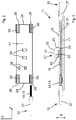
- eine Platine in der Draufsicht mit einem Leiter (noch nicht verbunden),
- Fig. 3
- eine LED-Insel im Längsschnitt mit angeschlossenen Leitern,
- Fig. 4
- die LED-Insel gemäß
Fig. 3 in der Draufsicht, - Fig. 5
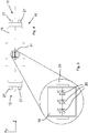
- einen vergrößerten Ausschnitt aus
Fig. 4 , nämlich eine Multichip-LED in der Draufsicht. - Ein in
Fig. 1 gezeigter LED-Streifen 10 besteht aus mehreren LED-Inseln 11, welche über Kabel 12 miteinander verbunden und an eine gemeinsame Spannungsversorgung 13 angeschlossen sind. Die einzelnen LED-Inseln 11 sind elektrisch parallel zueinander geschaltet. Dargestellt sind nur vier LED-Inseln 11. Tatsächlich können wesentlich mehr LED-Inseln 11 an der gemeinsamen Spannungsversorgung 13 zur Bildung eines entsprechend längeren LED-Streifens angeschlossen sein. Die Kabel 12 weisen in diesem Ausführungsbeispiel je zwei Leiter 14, 15 auf und können auch als zweiadriges System bezeichnet werden. Die Spannungsversorgung 13 ist vorzugsweise eine Konstantspannungsquelle. - Die Länge der einzelnen Kabel 12 ist insbesondere so bemessen, dass pro Meter Länge des LED-Streifens 10 fünf LED-Inseln 11 angeordnet sind. Dadurch ergeben sich die in
Fig. 1 dargestellten Abstände von 20 cm von der Mitte einer LED-Insel 11 zur Mitte der benachbarten LED-Insel 11. Alternativ können auch mehr LED-Inseln 11 pro Meter angeordnet sein. - Jede LED-Insel 11 weist gemäß
Fig. 3 eine von einer Umspritzmasse 16 umgebene Platine 17 auf. Auf der Platine 17 sind eine Multichip-LED 18 und ein elektrischer Widerstand 19 gehalten, insbesondere verlötet. Der elektrische Widerstand 19 ist inFig. 1 auch als R1 bezeichnet. Die Multichip-LED 18 weist in diesem Ausführungsbeispiel drei LEDs 20 auf, welche miteinander und mit dem Widerstand 19 elektrisch in Reihe geschaltet sind. In einem nicht gezeigten Ausführungsbeispiel sind vier LEDs je Multichip-LED vorgesehen. Widerstand 19 und Spannungsversorgung 13 sind dann entsprechend anzupassen. - Die Umspritzmasse 16 umfasst die Platine 17 von allen Seiten. Durchbrochen wird die Umspritzmasse 16 nur von einer hutförmigen Abdeckung 21 über der Multichip-LED 18 und durch an zwei Seiten zugeführte Kabel 12.
- Die hutförmige Abdeckung 21 liegt mit einem unteren umlaufenden Rand 22 auf der Platine 17 auf, insbesondere ohne die Multichip-LED 18 zu berühren. Dabei ist der untere Rand 22 mit einem radial auswärts gerichteten Kragen 23 versehen, sodass die Umspritzmasse 16 die Abdeckung 21 sicher hält.
- Gemäß
Fig. 2 ist die Platine 17 rechteckig ausgebildet mit einer Längsrichtung x, einer Querrichtung y und einer Dicke d. An Stirnseiten 24, 25 weist die Platine 17 jeweils außenseitig in Längsrichtung verlaufende Ausnehmungen 26 auf, die in Richtung der Dicke d durchgehen und in Längsrichtung x nach außen offen sind. Die Stirnseiten 24, 25 haben dadurch ein gabelförmiges Aussehen. - Zur Verbindung der Kabel 12 mit der Platine 17 werden die endseitig von einer Isolierung 27 befreiten Leiter 14, 15 in die Ausnehmungen 26 eingelegt und dort verlötet. Die Endposition der Leiter 14, 15 in den Ausnehmungen 26 ist in
Fig. 3 ersichtlich. Leiter 14, 15 und Ausnehmungen 26 weisen eine relativ große Überdeckung in Längsrichtung x auf, sodass eine relativ großflächige oder entlang zweier Linien verlaufende Lötverbindung möglich ist. Die sich ergebende Lötverbindung ist deutlich belastbarer als beispielsweise bei einem nur punktförmig mit der Platine 17 verbundenen Leiter. - Auf der Platine 17 sind Kontaktflächen 28, 29 zur elektrischen Verbindung mit dem Widerstand 19 und der Multichip-LED 18 vorgesehen. Von den Kontaktflächen 28, 29 verlaufen nicht gezeigte Leiterbahnen zu den Ausnehmungen 26, welche von elektrisch leitenden Rändern 30 eingefasst sind. Die Ränder 30 sind mit den Leitern 14, 15 verlötet und bilden Anschlusskontakte für die Leiter 14, 15.
- Die Abdeckung 21 ist aus durchsichtigem Kunststoff gefertigt und oberseitig nach Art einer Linse 31 ausgebildet. Gemäß
Fig. 3 weist die Linse 31 eine plane Unterseite 32 und eine konvexe Oberseite 33 auf. - Bedingt durch die Abdeckung 21 sind die Multichip-LED 18 und der Widerstand 19 räumlich und thermisch voneinander getrennt angeordnet. Unter der Abdeckung 21 ist nur die Multichip-LED 18 gehalten, während der Widerstand 19 außerhalb der Abdeckung 21 vorgesehen ist. Ein nachteiliger Wärmeausgleich vom Widerstand 19 zur Multichip-LED 18 ist im Wesentlichen nur mittelbar über die Platine 17 möglich. Auch ist der Widerstand 19 oberhalb der Platine 17 ringsum von der Umspritzmasse 16 bedeckt, so dass vom Widerstand 19 ausgehende Wärmestrahlung abgeschirmt wird.
- Die elektrischen Größen von Spannungsversorgung 13, Multichip-LED 18 und Widerstand 19 sind so aufeinander abgestimmt, dass die Multichip-LED 18 am unteren Rand ihrer Lichtstärke-Strom-Kennlinie betrieben wird, vorzugsweise mit 1 bis 10 Prozent des Nennstroms, insbesondere mit etwa 2,5 Prozent. Die Multichip-LED 18 weist insbesondere einen Lichtstrom von 30 bis 35 Lumen bei einem Nennstrom von 30 mA auf. Tatsächlich wird die Multichip-LED 18 vorzugsweise mit einem Dauerstrom von etwa 0,7 mA oder weniger betrieben. Bei fünf parallel geschalteten LED-Inseln 11 pro Meter Länge des LED-Streifens 10 ergibt sich dadurch ein Strombedarf von 3,5 mA pro Meter.
- Jede LED-Insel 11 strahlt Licht mit einer Lichtstärke von etwa 600 mcd ab.
-
10 LED-Streifen d Dicke 11 LED-Insel x Längsrichtung 12 Kabel y Querrichtung 13 Spannungsversorgung 14 Leiter 15 Leiter 16 Umspritzmasse 17 Platine 18 Multichip-LED 19 Widerstand 20 LEDs 21 Abdeckung 22 Rand 23 Kragen 24 Stirnseite 25 Stirnseite 26 Ausnehmungen 27 Isolierung 28 Kontaktflächen (Widerstand) 29 Kontaktflächen (Multichip-LED) 30 Ränder als Anschlusskontakte 31 Linse 32 Unterseite 33 Oberseite
Claims (18)
- LED-Streifen (10) mit wenigstens einer LED-Insel (11) und Kabeln (12) zum Anschluss an eine Spannungsversorgung (13) oder an weitere LED-Inseln (11), dadurch gekennzeichnet, dass auf der LED-Insel (11) mindestens eine Multichip-LED (18) und mindestens ein elektrischer Widerstand (19) in Reihe geschaltet vorgesehen sind.
- LED-Streifen nach Anspruch 1, dadurch gekennzeichnet, dass auf der LED-Insel (11) genau eine Multichip-LED (18) und genau ein elektrischer Widerstand (19) vorgesehen sind.
- LED-Streifen nach Anspruch 1 oder 2, dadurch gekennzeichnet, dass innerhalb einer Länge von 1 m fünf oder mehr LED-Inseln (11) über mehradrige Kabel (12) miteinander verbunden sind.
- LED-Streifen nach einem der Ansprüche 1 bis 3, dadurch gekennzeichnet, dass bei einer Gesamtlänge von 100 m nur ein zusätzlicher Anschluss für eine Einspeisung (13) vorgesehen ist.
- LED-Streifen nach einem der Ansprüche 1 bis 4, dadurch gekennzeichnet, dass die Multichip-LED (18) zwei oder mehr LEDs (20) aufweist, insbesondere drei bis fünf LEDs (20).
- LED-Streifen nach einem der Ansprüche 1 bis 5, dadurch gekennzeichnet, dass die Multichip-LED (18) nur LEDs (20) einer Lichtfarbe aufweist.
- LED-Streifen nach einem der Ansprüche 1 bis 6, dadurch gekennzeichnet, dass die Multichip-LED (18) ausschließlich oder überwiegend grünes Licht abstrahlt, vorzugsweise mit einem Intensitätsmaximum bei einer Wellenlänge von 520 bis 535 nm, insbesondere von 525 bis 530 nm.
- LED-Streifen nach einem der Ansprüche 1 bis 6, dadurch gekennzeichnet, dass die Multichip-LED (18) ausschließlich oder überwiegend weißes Licht abstrahlt, vorzugsweise mit einer Farbtemperatur von 3000 bis 5000 K.
- LED-Streifen nach einem der Ansprüche 1 bis 8, dadurch gekennzeichnet, dass die LED-Insel (11) Licht mit einer Lichtstärke von 300 bis 1200 mcd abstrahlt, insbesondere mit 500 bis 800 mcd, insbesondere mit 600 mcd.
- LED-Streifen nach einem der Ansprüche 1 bis 9, dadurch gekennzeichnet, dass die Multichip-LED (18) mit 0,3 bis 1,5 mA betrieben wird, insbesondere mit 0,5 bis 1,0 mA, vorzugsweise mit 0,7 mA.
- LED-Streifen nach einem der Ansprüche 1 bis 10, dadurch gekennzeichnet, dass die Multichip-LED (18) mit 0,5 bis 20 Prozent ihres Nennstroms betrieben wird, insbesondere mit 1 bis 10 Prozent, vorzugsweise mit 1,5 bis 5 Prozent.
- LED-Streifen nach einem der Ansprüche 1 bis 11, dadurch gekennzeichnet, dass die Multichip-LED (18) von einer hutförmigen Abdeckung (21) abgedeckt ist, wobei die Abdeckung (21) eine Oberseite (33) aufweist und außerhalb der Oberseite (33) zumindest teilweise von einer Umspritzmasse (16) umgeben ist.
- LED-Streifen nach Anspruch 12, dadurch gekennzeichnet, dass die Oberseite (33) der Abdeckung (21) als Teil einer Linse (31) für einen gezielten Lichtaustritt ausgebildet ist.
- LED-Streifen (10) mit wenigstens einer LED-Insel (11) und Kabeln (12) zum Anschluss an eine Spannungsversorgung (13) oder an weitere LED-Inseln (11), insbesondere nach einem der Ansprüche 1 bis 13, wobei die LED-Insel (11) eine Platine (17) mit Anschlusskontakten (30) aufweist, welche gabelförmig oder schlitzförmig ausgebildet sind.
- LED-Streifen nach Anspruch 14, dadurch gekennzeichnet, dass die Platine (17) eine Längsrichtung (x), eine Querrichtung (y) und eine Dicke (d) aufweist, und dass die Anschlusskontakte (30) an einander in Längsrichtung (x) gegenüberliegenden Stirnseiten (24, 25) der Platine (17) angeordnet und in Längsrichtung (x) ausgerichtet sind.
- Fluchtwegemarkierungssystem mit einem LED-Streifen (10) nach einem der Ansprüche 1 bis 15.
- Verfahren zum Betrieb eines LED-Streifens (10) nach einem der Ansprüche 1 bis 15 und mit wenigstens einer LED-Insel (11) und Kabeln (12) zum Anschluss an eine Spannungsversorgung (13) oder an weitere LED-Inseln (11), wobei auf der LED-Insel (11) mindestens eine Multichip-LED (18) und mindestens ein elektrischer Widerstand (19) in Reihe geschaltet vorgesehen sind, dadurch gekennzeichnet, dass die Multichip-LED (18) mit 0,3 bis 1,5 mA betrieben wird, insbesondere mit 0,5 bis 1,0 mA, vorzugsweise mit 0,7 mA.
- Verfahren zum Betrieb eines LED-Streifens (10) nach einem der Ansprüche 1 bis 15 und mit wenigstens einer LED-Insel (11) und Kabeln (12) zum Anschluss an eine Spannungsversorgung (13) oder an weitere LED-Inseln (11), wobei auf der LED-Insel (11) mindestens eine Multichip-LED (18) und mindestens ein elektrischer Widerstand (19) in Reihe geschaltet vorgesehen sind, insbesondere nach Anspruch 16, dadurch gekennzeichnet, dass die Multichip-LED (18) mit 0,5 bis 20 Prozent ihres Nennstroms betrieben wird, insbesondere mit 1 bis 10 Prozent, vorzugsweise mit 1,5 bis 5 Prozent.
Applications Claiming Priority (1)
| Application Number | Priority Date | Filing Date | Title |
|---|---|---|---|
| DE102020001001.6A DE102020001001A1 (de) | 2020-02-17 | 2020-02-17 | LED-Streifen |
Publications (3)
| Publication Number | Publication Date |
|---|---|
| EP3866568A1 true EP3866568A1 (de) | 2021-08-18 |
| EP3866568B1 EP3866568B1 (de) | 2024-08-28 |
| EP3866568C0 EP3866568C0 (de) | 2024-08-28 |
Family
ID=73855782
Family Applications (1)
| Application Number | Title | Priority Date | Filing Date |
|---|---|---|---|
| EP20215458.9A Active EP3866568B1 (de) | 2020-02-17 | 2020-12-18 | Led-streifen |
Country Status (2)
| Country | Link |
|---|---|
| EP (1) | EP3866568B1 (de) |
| DE (1) | DE102020001001A1 (de) |
Citations (5)
| Publication number | Priority date | Publication date | Assignee | Title |
|---|---|---|---|---|
| DE19627856A1 (de) | 1996-07-11 | 1998-01-15 | Happich Fahrzeug & Ind Teile | Beleuchtungsleiste und Verfahren zur Herstellung |
| US20090154156A1 (en) * | 2006-09-12 | 2009-06-18 | Paul Lo | Integrally Formed Single Piece Light Emitting Diode Light Wire and Uses Thereof |
| US20110305011A1 (en) * | 2006-09-12 | 2011-12-15 | Paul Lo | Integrally formed single piece light emitting diode light wire |
| US20140167632A1 (en) * | 2011-07-20 | 2014-06-19 | Koninklijke Philips N.V. | Light source comprising a led strip |
| DE202018104566U1 (de) * | 2018-08-08 | 2018-09-06 | Burkhard Herbach | Zweifach-spannungsfähige Beleuchtungseinrichtung |
-
2020
- 2020-02-17 DE DE102020001001.6A patent/DE102020001001A1/de active Pending
- 2020-12-18 EP EP20215458.9A patent/EP3866568B1/de active Active
Patent Citations (5)
| Publication number | Priority date | Publication date | Assignee | Title |
|---|---|---|---|---|
| DE19627856A1 (de) | 1996-07-11 | 1998-01-15 | Happich Fahrzeug & Ind Teile | Beleuchtungsleiste und Verfahren zur Herstellung |
| US20090154156A1 (en) * | 2006-09-12 | 2009-06-18 | Paul Lo | Integrally Formed Single Piece Light Emitting Diode Light Wire and Uses Thereof |
| US20110305011A1 (en) * | 2006-09-12 | 2011-12-15 | Paul Lo | Integrally formed single piece light emitting diode light wire |
| US20140167632A1 (en) * | 2011-07-20 | 2014-06-19 | Koninklijke Philips N.V. | Light source comprising a led strip |
| DE202018104566U1 (de) * | 2018-08-08 | 2018-09-06 | Burkhard Herbach | Zweifach-spannungsfähige Beleuchtungseinrichtung |
Also Published As
| Publication number | Publication date |
|---|---|
| EP3866568B1 (de) | 2024-08-28 |
| EP3866568C0 (de) | 2024-08-28 |
| DE102020001001A1 (de) | 2021-08-19 |
Similar Documents
| Publication | Publication Date | Title |
|---|---|---|
| EP2185857B1 (de) | Leuchtmodul | |
| DE10122666A1 (de) | Licht emittierendes Element vom rückseitig Licht emittierenden Chiptyp und isolierendes Substrat dafür | |
| DE102007059133A1 (de) | Substrat für ein LED-Submount und LED-Submount | |
| DE102008004238A1 (de) | Leuchtsystem | |
| DE20204263U1 (de) | Gebäudedachelement | |
| DE102015116855A1 (de) | Optoelektronisches Bauelement mit einem Leiterrahmen mit einer Versteifungsstruktur | |
| EP3540290A1 (de) | Led-lichtband | |
| WO2020030402A1 (de) | Zweifach-spannungsfähige beleuchtungseinrichtung | |
| EP3866568B1 (de) | Led-streifen | |
| EP3232746B1 (de) | Kontaktierung eines flexiblen leiterplattenstreifens durch eine kontaktierbrücke | |
| DE102013208400A1 (de) | LED-Band | |
| DE2641540C2 (de) | Lumineszenzdiodenzeile zur Erzeugung eines sehr feinen Rasters von Lichtpunkten | |
| DE202016104159U1 (de) | LED-Leuchtstreifen | |
| DE102012221250A1 (de) | Leuchtvorrichtung mit biegbarer Trägerplatte | |
| EP3007523A1 (de) | Anzeigevorrichtung | |
| DE102018107309B4 (de) | Transparente Anzeigevorrichtung | |
| DE102018109401A1 (de) | Stromschiene mit LEDs | |
| DE10238054B4 (de) | Elektrolumineszenz-Schild, insbesondere Kraftfahrzeug-Kennzeichenschild | |
| DE102013211457A1 (de) | Optoelektronische Baugruppe und Verfahren zum Herstellen einer optoelektronischen Baugruppe | |
| DE102009015224A1 (de) | LED-Lichtquelle mit einer Vielzahl von LED-Chips und LED-Chip zur Verwendung in selbiger | |
| DE102018211723A1 (de) | Led-anordnung und beleuchtungsvorrichtung | |
| DE202024100962U1 (de) | Elektrische Schaltungsanordnung für Beleuchtungszwecke | |
| DE20000936U1 (de) | Montageanordnung | |
| DE202009004852U1 (de) | Lichterkette | |
| DE102013018997B4 (de) | Anzeigeeinrichtung |
Legal Events
| Date | Code | Title | Description |
|---|---|---|---|
| PUAI | Public reference made under article 153(3) epc to a published international application that has entered the european phase |
Free format text: ORIGINAL CODE: 0009012 |
|
| STAA | Information on the status of an ep patent application or granted ep patent |
Free format text: STATUS: THE APPLICATION HAS BEEN PUBLISHED |
|
| AK | Designated contracting states |
Kind code of ref document: A1 Designated state(s): AL AT BE BG CH CY CZ DE DK EE ES FI FR GB GR HR HU IE IS IT LI LT LU LV MC MK MT NL NO PL PT RO RS SE SI SK SM TR |
|
| STAA | Information on the status of an ep patent application or granted ep patent |
Free format text: STATUS: REQUEST FOR EXAMINATION WAS MADE |
|
| 17P | Request for examination filed |
Effective date: 20220203 |
|
| RBV | Designated contracting states (corrected) |
Designated state(s): AL AT BE BG CH CY CZ DE DK EE ES FI FR GB GR HR HU IE IS IT LI LT LU LV MC MK MT NL NO PL PT RO RS SE SI SK SM TR |
|
| STAA | Information on the status of an ep patent application or granted ep patent |
Free format text: STATUS: EXAMINATION IS IN PROGRESS |
|
| 17Q | First examination report despatched |
Effective date: 20230616 |
|
| GRAP | Despatch of communication of intention to grant a patent |
Free format text: ORIGINAL CODE: EPIDOSNIGR1 |
|
| STAA | Information on the status of an ep patent application or granted ep patent |
Free format text: STATUS: GRANT OF PATENT IS INTENDED |
|
| INTG | Intention to grant announced |
Effective date: 20240516 |
|
| GRAS | Grant fee paid |
Free format text: ORIGINAL CODE: EPIDOSNIGR3 |
|
| GRAA | (expected) grant |
Free format text: ORIGINAL CODE: 0009210 |
|
| STAA | Information on the status of an ep patent application or granted ep patent |
Free format text: STATUS: THE PATENT HAS BEEN GRANTED |
|
| AK | Designated contracting states |
Kind code of ref document: B1 Designated state(s): AL AT BE BG CH CY CZ DE DK EE ES FI FR GB GR HR HU IE IS IT LI LT LU LV MC MK MT NL NO PL PT RO RS SE SI SK SM TR |
|
| REG | Reference to a national code |
Ref country code: CH Ref legal event code: EP |
|
| REG | Reference to a national code |
Ref country code: DE Ref legal event code: R096 Ref document number: 502020009018 Country of ref document: DE |
|
| REG | Reference to a national code |
Ref country code: IE Ref legal event code: FG4D Free format text: LANGUAGE OF EP DOCUMENT: GERMAN |
|
| U01 | Request for unitary effect filed |
Effective date: 20240919 |
|
| U07 | Unitary effect registered |
Designated state(s): AT BE BG DE DK EE FI FR IT LT LU LV MT NL PT RO SE SI Effective date: 20241011 |
|
| U20 | Renewal fee for the european patent with unitary effect paid |
Year of fee payment: 5 Effective date: 20241128 |
|
| PG25 | Lapsed in a contracting state [announced via postgrant information from national office to epo] |
Ref country code: NO Free format text: LAPSE BECAUSE OF FAILURE TO SUBMIT A TRANSLATION OF THE DESCRIPTION OR TO PAY THE FEE WITHIN THE PRESCRIBED TIME-LIMIT Effective date: 20241128 |
|
| PG25 | Lapsed in a contracting state [announced via postgrant information from national office to epo] |
Ref country code: GR Free format text: LAPSE BECAUSE OF FAILURE TO SUBMIT A TRANSLATION OF THE DESCRIPTION OR TO PAY THE FEE WITHIN THE PRESCRIBED TIME-LIMIT Effective date: 20241129 Ref country code: PL Free format text: LAPSE BECAUSE OF FAILURE TO SUBMIT A TRANSLATION OF THE DESCRIPTION OR TO PAY THE FEE WITHIN THE PRESCRIBED TIME-LIMIT Effective date: 20240828 |
|
| PG25 | Lapsed in a contracting state [announced via postgrant information from national office to epo] |
Ref country code: IS Free format text: LAPSE BECAUSE OF FAILURE TO SUBMIT A TRANSLATION OF THE DESCRIPTION OR TO PAY THE FEE WITHIN THE PRESCRIBED TIME-LIMIT Effective date: 20241228 |
|
| PG25 | Lapsed in a contracting state [announced via postgrant information from national office to epo] |
Ref country code: HR Free format text: LAPSE BECAUSE OF FAILURE TO SUBMIT A TRANSLATION OF THE DESCRIPTION OR TO PAY THE FEE WITHIN THE PRESCRIBED TIME-LIMIT Effective date: 20240828 |
|
| PG25 | Lapsed in a contracting state [announced via postgrant information from national office to epo] |
Ref country code: RS Free format text: LAPSE BECAUSE OF FAILURE TO SUBMIT A TRANSLATION OF THE DESCRIPTION OR TO PAY THE FEE WITHIN THE PRESCRIBED TIME-LIMIT Effective date: 20241128 Ref country code: ES Free format text: LAPSE BECAUSE OF FAILURE TO SUBMIT A TRANSLATION OF THE DESCRIPTION OR TO PAY THE FEE WITHIN THE PRESCRIBED TIME-LIMIT Effective date: 20240828 |
|
| PG25 | Lapsed in a contracting state [announced via postgrant information from national office to epo] |
Ref country code: RS Free format text: LAPSE BECAUSE OF FAILURE TO SUBMIT A TRANSLATION OF THE DESCRIPTION OR TO PAY THE FEE WITHIN THE PRESCRIBED TIME-LIMIT Effective date: 20241128 Ref country code: PL Free format text: LAPSE BECAUSE OF FAILURE TO SUBMIT A TRANSLATION OF THE DESCRIPTION OR TO PAY THE FEE WITHIN THE PRESCRIBED TIME-LIMIT Effective date: 20240828 Ref country code: NO Free format text: LAPSE BECAUSE OF FAILURE TO SUBMIT A TRANSLATION OF THE DESCRIPTION OR TO PAY THE FEE WITHIN THE PRESCRIBED TIME-LIMIT Effective date: 20241128 Ref country code: IS Free format text: LAPSE BECAUSE OF FAILURE TO SUBMIT A TRANSLATION OF THE DESCRIPTION OR TO PAY THE FEE WITHIN THE PRESCRIBED TIME-LIMIT Effective date: 20241228 Ref country code: HR Free format text: LAPSE BECAUSE OF FAILURE TO SUBMIT A TRANSLATION OF THE DESCRIPTION OR TO PAY THE FEE WITHIN THE PRESCRIBED TIME-LIMIT Effective date: 20240828 Ref country code: GR Free format text: LAPSE BECAUSE OF FAILURE TO SUBMIT A TRANSLATION OF THE DESCRIPTION OR TO PAY THE FEE WITHIN THE PRESCRIBED TIME-LIMIT Effective date: 20241129 Ref country code: ES Free format text: LAPSE BECAUSE OF FAILURE TO SUBMIT A TRANSLATION OF THE DESCRIPTION OR TO PAY THE FEE WITHIN THE PRESCRIBED TIME-LIMIT Effective date: 20240828 |
|
| PG25 | Lapsed in a contracting state [announced via postgrant information from national office to epo] |
Ref country code: SM Free format text: LAPSE BECAUSE OF FAILURE TO SUBMIT A TRANSLATION OF THE DESCRIPTION OR TO PAY THE FEE WITHIN THE PRESCRIBED TIME-LIMIT Effective date: 20240828 |
|
| PG25 | Lapsed in a contracting state [announced via postgrant information from national office to epo] |
Ref country code: CZ Free format text: LAPSE BECAUSE OF FAILURE TO SUBMIT A TRANSLATION OF THE DESCRIPTION OR TO PAY THE FEE WITHIN THE PRESCRIBED TIME-LIMIT Effective date: 20240828 |
|
| PG25 | Lapsed in a contracting state [announced via postgrant information from national office to epo] |
Ref country code: SK Free format text: LAPSE BECAUSE OF FAILURE TO SUBMIT A TRANSLATION OF THE DESCRIPTION OR TO PAY THE FEE WITHIN THE PRESCRIBED TIME-LIMIT Effective date: 20240828 |
|
| PLBE | No opposition filed within time limit |
Free format text: ORIGINAL CODE: 0009261 |
|
| STAA | Information on the status of an ep patent application or granted ep patent |
Free format text: STATUS: NO OPPOSITION FILED WITHIN TIME LIMIT |
|
| PG25 | Lapsed in a contracting state [announced via postgrant information from national office to epo] |
Ref country code: MC Free format text: LAPSE BECAUSE OF FAILURE TO SUBMIT A TRANSLATION OF THE DESCRIPTION OR TO PAY THE FEE WITHIN THE PRESCRIBED TIME-LIMIT Effective date: 20240828 |
|
| REG | Reference to a national code |
Ref country code: CH Ref legal event code: PL |
|
| 26N | No opposition filed |
Effective date: 20250530 |
|
| PG25 | Lapsed in a contracting state [announced via postgrant information from national office to epo] |
Ref country code: CH Free format text: LAPSE BECAUSE OF NON-PAYMENT OF DUE FEES Effective date: 20241231 |
|
| PG25 | Lapsed in a contracting state [announced via postgrant information from national office to epo] |
Ref country code: IE Free format text: LAPSE BECAUSE OF NON-PAYMENT OF DUE FEES Effective date: 20241218 |
|
| U20 | Renewal fee for the european patent with unitary effect paid |
Year of fee payment: 6 Effective date: 20251127 |
|
| PGFP | Annual fee paid to national office [announced via postgrant information from national office to epo] |
Ref country code: GB Payment date: 20251218 Year of fee payment: 6 |