EP3540290A1 - Led-lichtband - Google Patents
Led-lichtband Download PDFInfo
- Publication number
- EP3540290A1 EP3540290A1 EP19161039.3A EP19161039A EP3540290A1 EP 3540290 A1 EP3540290 A1 EP 3540290A1 EP 19161039 A EP19161039 A EP 19161039A EP 3540290 A1 EP3540290 A1 EP 3540290A1
- Authority
- EP
- European Patent Office
- Prior art keywords
- printed circuit
- pcb
- leds
- rigid
- circuit board
- Prior art date
- Legal status (The legal status is an assumption and is not a legal conclusion. Google has not performed a legal analysis and makes no representation as to the accuracy of the status listed.)
- Pending
Links
Images

Classifications
-
- F—MECHANICAL ENGINEERING; LIGHTING; HEATING; WEAPONS; BLASTING
- F21—LIGHTING
- F21S—NON-PORTABLE LIGHTING DEVICES; SYSTEMS THEREOF; VEHICLE LIGHTING DEVICES SPECIALLY ADAPTED FOR VEHICLE EXTERIORS
- F21S4/00—Lighting devices or systems using a string or strip of light sources
- F21S4/20—Lighting devices or systems using a string or strip of light sources with light sources held by or within elongate supports
- F21S4/22—Lighting devices or systems using a string or strip of light sources with light sources held by or within elongate supports flexible or deformable, e.g. into a curved shape
-
- H—ELECTRICITY
- H05—ELECTRIC TECHNIQUES NOT OTHERWISE PROVIDED FOR
- H05K—PRINTED CIRCUITS; CASINGS OR CONSTRUCTIONAL DETAILS OF ELECTRIC APPARATUS; MANUFACTURE OF ASSEMBLAGES OF ELECTRICAL COMPONENTS
- H05K1/00—Printed circuits
- H05K1/02—Details
- H05K1/14—Structural association of two or more printed circuits
- H05K1/147—Structural association of two or more printed circuits at least one of the printed circuits being bent or folded, e.g. by using a flexible printed circuit
-
- H—ELECTRICITY
- H05—ELECTRIC TECHNIQUES NOT OTHERWISE PROVIDED FOR
- H05K—PRINTED CIRCUITS; CASINGS OR CONSTRUCTIONAL DETAILS OF ELECTRIC APPARATUS; MANUFACTURE OF ASSEMBLAGES OF ELECTRICAL COMPONENTS
- H05K3/00—Apparatus or processes for manufacturing printed circuits
- H05K3/36—Assembling printed circuits with other printed circuits
- H05K3/361—Assembling flexible printed circuits with other printed circuits
- H05K3/363—Assembling flexible printed circuits with other printed circuits by soldering
-
- F—MECHANICAL ENGINEERING; LIGHTING; HEATING; WEAPONS; BLASTING
- F21—LIGHTING
- F21Y—INDEXING SCHEME ASSOCIATED WITH SUBCLASSES F21K, F21L, F21S and F21V, RELATING TO THE FORM OR THE KIND OF THE LIGHT SOURCES OR OF THE COLOUR OF THE LIGHT EMITTED
- F21Y2103/00—Elongate light sources, e.g. fluorescent tubes
- F21Y2103/10—Elongate light sources, e.g. fluorescent tubes comprising a linear array of point-like light-generating elements
-
- F—MECHANICAL ENGINEERING; LIGHTING; HEATING; WEAPONS; BLASTING
- F21—LIGHTING
- F21Y—INDEXING SCHEME ASSOCIATED WITH SUBCLASSES F21K, F21L, F21S and F21V, RELATING TO THE FORM OR THE KIND OF THE LIGHT SOURCES OR OF THE COLOUR OF THE LIGHT EMITTED
- F21Y2107/00—Light sources with three-dimensionally disposed light-generating elements
- F21Y2107/70—Light sources with three-dimensionally disposed light-generating elements on flexible or deformable supports or substrates, e.g. for changing the light source into a desired form
-
- F—MECHANICAL ENGINEERING; LIGHTING; HEATING; WEAPONS; BLASTING
- F21—LIGHTING
- F21Y—INDEXING SCHEME ASSOCIATED WITH SUBCLASSES F21K, F21L, F21S and F21V, RELATING TO THE FORM OR THE KIND OF THE LIGHT SOURCES OR OF THE COLOUR OF THE LIGHT EMITTED
- F21Y2115/00—Light-generating elements of semiconductor light sources
- F21Y2115/10—Light-emitting diodes [LED]
-
- H—ELECTRICITY
- H05—ELECTRIC TECHNIQUES NOT OTHERWISE PROVIDED FOR
- H05K—PRINTED CIRCUITS; CASINGS OR CONSTRUCTIONAL DETAILS OF ELECTRIC APPARATUS; MANUFACTURE OF ASSEMBLAGES OF ELECTRICAL COMPONENTS
- H05K2201/00—Indexing scheme relating to printed circuits covered by H05K1/00
- H05K2201/09—Shape and layout
- H05K2201/09145—Edge details
- H05K2201/09181—Notches in edge pads
-
- H—ELECTRICITY
- H05—ELECTRIC TECHNIQUES NOT OTHERWISE PROVIDED FOR
- H05K—PRINTED CIRCUITS; CASINGS OR CONSTRUCTIONAL DETAILS OF ELECTRIC APPARATUS; MANUFACTURE OF ASSEMBLAGES OF ELECTRICAL COMPONENTS
- H05K2201/00—Indexing scheme relating to printed circuits covered by H05K1/00
- H05K2201/10—Details of components or other objects attached to or integrated in a printed circuit board
- H05K2201/10007—Types of components
- H05K2201/10106—Light emitting diode [LED]
Definitions
- the light-emitting semiconductor bodies of the LED chips can be based on inorganic electroluminescent materials, as is the case with semiconductor LEDs, or organic electroluminescent materials, as is the case, for example, with OLEDs (Organic Light Emitting Diode).
- LED component and LED chip are hereinafter referred to uniformly with "LED” and includes inorganic LED chips and organic LED chips.
- a flexible linear LED strip light for use in one of the presently explained embodiments, embodiments and exemplary embodiments is described, for example, in the data sheet BLONE1300024DC12000830000W20 (available at https://cdn2.regroshop.at/medias/sysregro/ sheets / sheets / h03 / hd8 /9006597767198/Te-BL124120003020.pdf ).
- This is a topview LED strip light where the optical beams of the LED components mounted on the Flex PCB are nominally perpendicular to the mounting surface of the Flex PCB.
- Such flexible LED strip lights can be manufactured in any continuous lengths. Same structures can repeat themselves at regular intervals, for example every 5cm. Such a LED light band is then separable at regular intervals. When installing curves are possible. Depending on the desired lumen output, such a LED light band can be operated up to a length of approx. 20 meters without additional energy supply between its ends. They can be quickly and easily mounted, for example, in an aluminum profile and allow secure mounting, for example by means of a double-sided adhesive tape. Likewise is a sufficiently good Thermal management possible, because the thin base material of a Flex-PCB, for example polyimide (50 ⁇ m + 18 ⁇ m adhesive layer), allows good heat transfer into the aluminum profile.
- a Flex-PCB for example polyimide (50 ⁇ m + 18 ⁇ m adhesive layer)
- rigid PCB such as a so-called FR4 printed circuit board.
- the connection area of a Flex-PCB has a lower mechanical strength, so that an effective strain relief is difficult to achieve.
- the electrical contacting of a flex-PCB is more difficult, since commercial connectors require a certain amount of space both above and below the flex, which impairs the thermal management in this area of the contacting.
- Components such as connectors, clamps and optics can only be installed with considerable technical effort, if at all.
- An electrical intermediate feed, for example, in the middle of the flex-PCB is, if at all possible only with great technical effort, because of the difficult electrical contact, since plug or Clamping, if at all, can be mounted only with great technical effort.
- dark spots are unavoidable at the points where electrical contact is made. No LEDs are placed between the end of the flex PCB where contact pads are located and a required strain relief after the end of the flex PCB.
- an orientation of the flex PCBs in connection with layer-dependent optics is very expensive. Constant placement of the FLEX PCB must be maintained over the entire strip length.
- One possibility for multilayer configurations does not exist; only a simple connection is possible.
- the object is to provide an improved light-emitting diode strip of the type mentioned, which reduces in particular the disadvantages described above.
- this has at least one flexible linear LED light band of the beginning mentioned type, which comprises an elongated flexible printed circuit board, ie a flex PCB, on which a plurality of LEDs mounted and electrically interconnected.
- a flex PCB On at least one end of the flex PCB is a - in particular elongate - rigid circuit board, that is arranged a rigid PCB, on which a further plurality of LEDs mounted and electrically interconnected.
- the LEDs are mounted on the flex PCB and on the - in particular elongated - rigid PCB in particular identical geometrical arrangement and interconnected in particular identically electrically.
- a uniform light emission pattern can be achieved by the LED light band as a whole, ie the light emission patterns on the one hand are based on LEDs on the flex PCB and on the other hand on the LEDs on the rigid PCB are identical.
- identical is meant here in particular, that geometric arrangement, electrical interconnection and light emission pattern identifiable identical within the scope of normal manufacturing tolerances and identifiable to the human eye, that is virtually identical and not exactly metrologically exactly identical or otherwise physically exactly identical.
- the LED light band has a plurality of flex PCBs, and a rigid PCB each having a plurality of LEDs electrically connected to the plurality of LEDs of the adjacent flex PCB is disposed between each of two of the flex PCBs.
- the LED light band on at least one arranged between two flex PCB rigid-PCB electrical connection elements to electrical energy supply in the LED strip light on.
- all existing rigid PCBs have connection elements for the electrical energy input into the LED light band.
- the LED light strip based on a combination of at least one flexible, ribbon-shaped printed circuit board (Flex-PCB) and at least one rigid printed circuit board (rigid PCB), the overall arrangement of the LEDs present on the Flex PCB and specification of the light output is unchanged Art continued on the rigid PCB.
- Flexible, ribbon-shaped printed circuit board Flexible PCB
- rigid PCB rigid printed circuit board
- additional electronic and / or mechanical components are mounted on the rigid PCB.
- a Double-sided Flex PCB solution with electronic and / or mechanical components mounted on the back of the Flex-PCB would increase the meter price of flexible LED strips by at least a factor of 3. Only a few additional features could be obtained for the Flex-PCB. Furthermore, the connection technology can be largely standardized, resulting in cost advantages in the assembly of the populated LED strip.
- Plugs and strain reliefs can be realized, for example, at the end of the flexible LED light band without dark spot or other changes in the light parameters.
- connectors and strain reliefs can be mounted on Rigid PCBs arranged there, without causing dark spots or other changes in the light parameters, whereby an increase in the possible lengths of LED light strips can be achieved.
- Special electronic functions, such as intelligent temperature monitoring, motion sensors, CO2 sensor technology as well as communication devices can be realized on the rigid PCB (s) as an LED strip lighting extension.
- the rigid PCB like the Flex PCB, can be mounted with a thermally conductive double-sided adhesive tape, for example, in an aluminum profile.
- a solder joint is provided as an electrical and / or mechanical connection between flex PCB and rigid PCB.
- a single-layer FR4 PCB can be used as the rigid PCB.
- rigid multilayer printed circuit boards can be used.
- For high performance for example, offer metal core conductor plates.
- the LED light strip 1 comprises an elongated flexible ribbon-shaped printed circuit board 2 (Flex-PCB) on which a plurality of LEDs 10 mounted and electrically connected by means of electrical traces on the flex PCB 2.
- the LEDs 10 are mounted linearly one behind the other at constant distances from each other on the flex PCB 2.
- the LEDs 10 are each, for example, an LED chip provided with a lead-frame-based plastic sheath, for example PLCC2 SMD LEDs, PLCC4 SMD LEDs or PLCC6 SMD LEDs, high-power SMD LEDs and / or SMD LED chip arrays. Housings (so-called CAS-LEDs) which are mounted in Surface (SMD) mounting technology on the Flex-PCB 2 and electrically interconnected.
- SMD Surface
- Such a flexible linear LED strip light is described, for example, in the data sheet BLONE1300024DC12000830000W20 (available at https://cdn2.regroshop.at/medias/sys Regro / sheets / sheets / h03 / hd8 / 9006597767198 / Te-BL124120003020.pdf ).
- the LEDs 10 are LED chips mounted on the flex PCB 2 in chip-on-board (COB) technology and electrically interconnected.
- COB chip-on-board
- phosphor material for light conversion can be integrated. Additionally or alternatively, remote phosphor technology can be used in the LED strip light.
- a rigid circuit board 3 (rigid PCB) is arranged and with the flex PCB. 2
- the flex PCB 2 For example, mechanically connected via solder joints 6 or other suitable connection means.
- electrical interconnects on the one hand of the flex PCB 2 and on the other hand of the rigid PCB 3 can be electrically connected to one another via these solder joints 6.
- separate electrical connection means for example wire connections between flex PCB 2 and rigid PCB 3 may be provided, to which the conductor tracks on the one hand of flex PCB 2 and on the other hand of rigid PCB 3 are electrically connected.
- a further plurality of LEDs 10 is mounted and electrically interconnected.
- the LEDs 10 of the rigid PCB 3 are electrically connected to the LEDs 10 of the flex PCB 2.
- the LEDs 10 on the rigid PCB 3 are nominally identical to the LEDs 10 on the flex PCB and are there linearly arranged one behind the other at the same distances from each other and electrically connected according to the same geometric pattern as on the flex PCB 2.
- the two adjacent LEDs 10 on the one hand on the flex PCB 2 and on the other hand on the rigid PCB 3 have the same distance from each other as the other LEDs 10 on the flex PCB 2 and the rigid PCB 3 with each other. Consequently, the partial LED light band of the flex PCB 2 and the partial LED light band of the rigid PCB 3 are not different from one another in terms of their light emission characteristic, so that a uniform illumination image of the entire LED light band 1 appears to the viewer.
- the rigid PCB 3 is integrated in this way, so to speak, in the LED light band 1.
- the LEDs 10 on the flex PCB 2 and on the rigid PCB 3 are consistently mounted in an identical geometric arrangement and consistently electrically interconnected with each other, such that the light emission from the flex PCB 2 and the light emission starting from the rigid PCB. 3 are so largely identical that the viewer from the outside with respect to light emission no difference between Flex-PCB 2 and Rigid-PCB 3 is recognizable.
- electronic and / or mechanical components 4 are mounted on the rigid-type PCB 3 in addition to the LEDs 10. Functionalities of such additional electronic and / or mechanical components 4 on the rigid-PCB 3 are already exemplified above in the general part of the description.
- a dressingleitklebeband 7 or a continuous PCB through both trenchleitklebeband 7 is provided by means of which the LED light strip 1, for example in an aluminum profile of a housing for the LED Light band 1 can be attached.
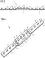
- FIGS. 3 and 4 illustrated second embodiment differs from the above-described first embodiment substantially in that two flex PCBs 2 are provided, between which a rigid PCB 3 is arranged.
- the LEDs 10 on the flex PCBs 2 and the rigid PCB 3 are formed, mounted and electrically interconnected, for example, analogously to the first exemplary embodiment.
- the flex PCBs 2 and the rigid PCB 3 are analogous to the corresponding PCBs of the formed first embodiment, interconnected and electrically interconnected.
- electrical connection elements 5 for supplying power to the LED light band 1 are provided on the rigid-PCB 3.
- the LED light band 1 has three or more flex PCBs 2 and is respectively sandwiched between two flex PCBs 2 according to the embodiment described above FIGS. 3 and 4 mounted a rigid PCB 3, the LEDs 10 are mounted analogously to the embodiments described above and electrically interconnected.
- electrical connection elements 5 may be provided for electrical energy supply.
- a plurality of flex PCBs 2 and at least one rigid PCB 3 are provided, which according to the embodiment described above according to the FIGS. 3 and 4 is mounted between two of the flex PCBs 2.
- the LEDs 10 of the rigid PCB 3 is electrically connected to the LEDs 10 of the mutually adjacent flex PCBs 2.
- electrical connection elements for the electrical energy supply in the LED light band 1 are provided.
- the LED light band 1 has a plurality of flex PCBs 2 with at least two groups of flex PCBs 2, between which according to the embodiment described above according to FIGS FIGS. 3 and 4 a rigid PCB 3 is mounted.
- the LEDs 10 of the rigid PCB 3 is with the LEDs 10 on both sides electrically connected to adjacent groups of flex PCBs.
- At least one of the groups of flex PCBs 2 has at least two flex PCBs 2.
- rigid-PCB 3 for example, electrical connection elements for the electrical energy supply in the LED light band 1 are provided.
Abstract
Es ist ein LED-Lichtband (1) angegeben, das mindestens eine langgestreckte flexible Leiterplatte (2) aufweist, auf der eine Mehrzahl von LEDs (10) montiert und elektrisch verschaltet ist. An einem Ende der langgestreckten flexiblen Leiterplatte (2) ist eine starre Leiterplatte (3) angeordnet und in das LED-Lichtband (1) integriert, auf der eine weitere Mehrzahl von LEDs (10) montiert und elektrisch verschaltet ist, welche mit den LEDs (10) auf der langgestreckten flexiblen Leiterblatte (2) elektrisch verschaltet sind. Bei einer Ausführungsform ist eine Mehrzahl von langgestreckten flexiblen Leiterplatten (2) und mindestens eine starre Leiterplatte (3) vorgesehen, die zwischen zwei langgestreckten flexiblen Leiterplatten (2) angeordnet ist.
Description
- Die vorliegende Erfindung betrifft ein Leuchtdioden-Lichtband (im Folgenden "LED-Lichtband"), bei dem eine Mehrzahl von
- LED-Bauelementen - beispielsweise mit einer leadframebasierten Kunststoffumhüllung versehene LED-Chips wie beispielsweise PLCC2 SMD LEDs, PLCC4 SMD LEDs oder PLCC6 SMD LEDs, High-Power SMD LEDs und/oder LED-Chip-Arrays in SMD-Gehäusen (sogenannten CAS-LEDs) - beispielsweise in Oberflächen(SMD)-Montagetechnologie oder
- eine Mehrzahl von LED-Chips in Chip-on-board (COB)-Technologie
- Die lichtemittierenden Halbleiterkörper der LED-Chips können dabei auf anorganischen elektrolumineszierenden Materialien, wie es bei Halbleiter-LEDs der Fall ist, oder organischen elektrolumineszierenden Materialien, wie es beispielsweise bei OLEDs (Organic Light Emitting Diode) der Fall ist, basieren.
- LED-Bauelement und LED-Chip werden im Folgenden einheitlich mit "LED" bezeichnet und schließt anorganische LED-Chips sowie organische LED-Chips ein.
- Ein flexibles lineares LED-Lichtband zur Verwendung in einem gemäß einer der vorliegend erläuterten Ausführungsformen, Ausgestaltungen und Ausführungsbeispielen ist beispielsweise im Datenblatt BLONE1300024DC12000830000W20 (verfügbar unter https://cdn2.regroshop.at/medias/sys Regro/sheets/sheets/h03/ hd8/9006597767198/Te-BL124120003020.pdf) beschrieben. Hierbei handelt es sich um ein Topview-LED-Lichtband, bei dem die optischen Abstrahlachsen der auf dem Flex-PCB montierten LED-Bauelemente nominal senkrecht zur Montagefläche des Flex-PCBs verlaufen.
- Derartige flexible LED-Lichtbänder werden herkömmlich entweder mit an deren Enden angelöteten Kabeln oder an deren Enden angeordneten speziellen Steckverbindern elektrisch an eine Energieversorgung und ggf. elektronische Steuerung angeschlossen.
- Solche flexiblen LED-Lichtbänder können in beliebigen durchgängigen Längen hergestellt werden. Gleiche Strukturen können sich in regelmäßigen Abständen wiederholen, beispielsweise alle 5cm. Ein solches LED-Lichtband ist dann in regelmäßigen Abständen trennbar. Beim Verbau sind Rundungen möglich. Abhängig vom gewünschten Lumen-Output kann ein solches LED-Lichtband bis zu einer Länge von ca. 20 Metern ohne zusätzliche Energieeinspeisung zwischen dessen Enden betrieben werden. Sie können schnell und einfach beispielsweise in einem Aluminiumprofil montiert werden und ermöglichen eine sichere Montage beispielsweise mittels eines doppelseitigen Klebebandes. Ebenso ist ein hinreichend gutes Wärmemanagement möglich, denn das dünne Basismaterial eines Flex-PCBs, beispielsweise Polyimid (50 µm + 18 µm Klebstoffschicht), ermöglicht eine gute Wärmeübertragung in das Aluminium-Profil. Mittels des doppelseitigen, wärmeleitenden Klebebands kann eine gute Wärmeankopplung zwischen Flex-PCB und Trägerprofil aus Aluminium realisiert werden, denn das Flex-PCB passt sich sehr gut an die Oberfläche des Trägerprofis an. Das Flex-PCB kann Wärmespannung gut ausgleichen und vermeidet damit thermisch bedingte Abhebungen.
- Herkömmliche flexible LED-Bänder ermöglichen eine einfache Logistik, benötigen geringes Lagervolumen und können standardisiert bei der Montage abgelängt werden. Damit eröffnen sie hohe Flexibilität in der Anwendung, hohe Betriebszuverlässigkeit und geringe Systemkosten.
- Dem stehen einige Nachteile im Vergleich zu einer starren Leiterplatte (im Folgenden "Starr-PCB"), wie beispielsweise eine sogenannte FR4-Leiterplatte, gegenüber. Der Anschlussbereich eines Flex-PCB weist eine geringere mechanische Festigkeit auf, sodass eine wirkungsvolle Zugentlastung nur schwer möglich ist. Die elektrische Kontaktierung eines Flex-PCB ist schwieriger, da handelsübliche Steckverbinder sowohl oberhalb als auch unterhalb der Flex einen gewissen Raum benötigen, was das Wärmemanagement in diesem Bereich der Kontaktierung beeinträchtigt. Komponenten wie Steckverbinder, Klemmen und Optiken können, wenn überhaupt, nur mit größerem technischen Aufwand montiert werden. Eine elektrische Zwischeneinspeisung beispielsweise in der Mitte des Flex-PCB ist, wenn überhaupt, nur mit großem technischen Aufwand möglich, wegen der schwierigen elektrischen Kontaktierung, da Steck- oder Klemmvorrichtungen, wenn überhaupt, nur mit großem technischen Aufwand montiert werden können. Bei der Montage eines Flex-PCB in einem Montage-Profil sind an den Stellen, an denen die elektrische Kontaktierung erfolgt, Dunkelstellen unvermeidbar. Zwischen dem Ende des Flex-PCBs, an dem Kontaktpads angeordnet sind, und einer erforderlichen Zugentlastung nach dem Ende des Flex-PCBs sind keine LEDs angeordnet. Zudem ist eine Ausrichtung des Flex-PCBs im Zusammenhang mit lagenabhängigen Optiken sehr aufwendig. Eine gleichbleibende Bestückung des FLEX-PCBs muss über die komplette Bandlänge aufrechterhalten werden. Eine Möglichkeit für Multilayer-Konfigurationen besteht nicht; es ist nur eine einfache Beschaltung möglich. Hinzu kommt eine begrenzte Stromtragfähigkeit, insbesondere aufgrund einer geringen maximalen Kupferschichtdicke. Zusammenfassend ist zu sagen, dass ein Flex-PCB nahezu ungeeignet für die Bestückung mit mechanischen Bauteilen ist und, wenn überhaupt, nur mit großem technischen Aufwand Funktionalitäten außerhalb Lichterzeugung und -abgabe übernehmen kann.
- Vorliegend liegt insbesondere die Aufgabe zugrunde, ein verbessertes Leuchtdioden-Lichtband der eingangs genannten Art bereitzustellen, welches insbesondere die oben geschilderten Nachteile reduziert.
- Diese Aufgabe wird durch ein Leuchtdioden-Lichtband mit den Merkmalen des Patenanspruches 1 gelöst. Vorteilhafte Ausgestaltungen sind in den Unteransprüchen angegeben. Der Offenbarungsgehalt der Patentansprüche wird hiermit durch Rückbezug in die vorliegende Beschreibung aufgenommen.
- Bei einer Ausführungsform des LED-Lichtbandes weist dieses mindestens ein flexibles lineares LED-Lichtband der eingangs genannten Art auf, welches eine langgestreckte flexible Leiterplatte, also ein Flex-PCB umfasst, auf der eine Mehrzahl von LEDs montiert und elektrisch verschaltet ist. An mindestens einem Ende des Flex-PCB ist eine - insbesondere langgestreckte - starre Leiterplatte, also ein Starr-PCB angeordnet, auf der eine weitere Mehrzahl von LEDs montiert und elektrisch verschaltet ist.
- Bei einer Ausführungsform sind die LEDs auf dem Flex-PCB und auf dem - insbesondere langgestreckten - Starr-PCB in insbesondere identischer geometrischer Anordnung montiert und in insbesondere identisch elektrisch verschaltet. Dadurch kann ein einheitliches Lichtabstrahlungsmuster von dem LED-Lichtband insgesamt erzielt werden, sprich die Lichtabstrahlungsmuster zum einen ausgehend von LEDs auf dem Flex-PCB und zum anderen ausgehend von den LEDs auf dem Starr-PCB sind identisch. Mit "identisch" ist hier durchweg insbesondere gemeint, dass geometrische Anordnung, elektrische Verschaltung und Lichtabstrahlungsmuster nur im Rahmen der üblichen Fertigungstoleranzen und für das menschliche Auge erkennbar identisch, das heißt praktisch identisch und nicht insbesondere messtechnisch exakt identisch oder anderweitig physikalisch exakt identisch sind.
- Bei einer Ausführungsform weist das LED-Lichtband eine Mehrzahl von Flex-PCBs auf und ist jeweils zwischen zwei dieser Flex-PCBs ein Starr-PCB angeordnet, deren Mehrzahl von LEDs mit der Mehrzahl von LEDs des benachbarten Flex-PCBs elektrisch verschaltet ist.
- Bei einer hierzu weitergehenden Ausführungsform weist das LED-Lichtband an mindestens einem zwischen zwei Flex-PCBs angeordneten Starr-PCB elektrische Anschlusselemente zur elektrischen Energieeinspeisung in das LED-Lichtband auf. Bei einer anderen Ausführungsform weisen alle vorhandenen Starr-PCBs Anschlusselemente zur elektrischen Energieeinspeisung in das LED-Lichtband auf.
- Bei einer Ausführungsform des LED-Lichtbandes auf Basis einer Kombination aus mindestens einer flexiblen, bandförmigen Leiterplatte (Flex-PCB) und mindestens einer starren Leiterplatte (Starr-PCB) ist die auf dem Flex-PCB vorhandene Gesamtanordnung der LEDs und Spezifikation der Lichtabgabe in unveränderter Art auf dem Starr-PCB weitergeführt.
- Zusätzlich sind bei einer weiteren Ausführungsform auf dem Starr-PCB zusätzliche elektronische und/oder mechanische Komponenten montiert.
- Durch eine solche Hybrid-Lösung können die Vorteile des Flex-PCBs voll genutzt werden, während dessen Nachteile durch das Starr-PCB ausgeglichen werden.
- Sämtliche Ausführungsformen nutzen die Kompatibilität von Flex-PCB und Starr-PCB bezüglich der Licht-Parameter. Eine solche Hybridlösung mit Flex-PCB und Starr-PCB bringt sowohl technische als auch wirtschaftliche Vorteile mit sich. So sind bedeutende funktionelle Erweiterungen bei linearen Licht-Bändern möglich, die mit Flex-PCBs alleine, wenn überhaupt, nur mit großem Aufwand realisiert werden können. Das Flex-PCB kann bis zu den elektrischen Anschlüssen, beispielsweise Anschluss-Pads, mittels Kleben montiert werden. Damit ist eine gute Wärmeankopplung des Flex-PCB auch im Bereich von elektrischen Anschlüssen möglich. Zudem bleibt die technische Einfachheit der Herstellung von LED-Lichtbändern mit Flex-PCB weitgehend erhalten. Eine doppelseitige Flex-PCB-Lösung, bei dem elektronische und/oder mechanische Komponenten auf der Rückseite des Flex-PCB montiert sind, würde den Meter-Preis von flexiblen LED-Lichtbändern mindestens um den Faktor 3 erhöhen. Es könnten nur wenige Zusatzeigenschaften für das Flex-PCB gewonnen werden. Des Weiteren kann die Anschlusstechnik weitgehend standardisiert werden, wodurch sich Kostenvorteile in der Montage des bestückten LED-Bandes ergeben.
- Sämtlichen Ausführungsformen mit den mit LEDs bestückten Starr-PCBs ist gemein, dass darauf zusätzliche mechanische und/oder elektronische Komponenten auf technisch einfache Weise montiert werden können. Stecker und Zugentlastungen können beispielsweise am Ende des flexiblen LED-Lichtbandes ohne Dunkelstelle oder anderweitiger Änderungen der Lichtparameter verwirklicht werden. Im Verlauf des flexiblen LED-Lichtbandes können an dort angeordneten Starr-PCBs Stecker und Zugentlastungen montiert werden, ohne Dunkelstellen oder anderweitige Änderungen der Lichtparameter zu verursachen, wodurch eine Vergrößerung der möglichen Längen von LED-Lichtbändern erzielt werden kann. Spezielle elektronische Funktionen, wie beispielsweise intelligente Temperaturüberwachung, Bewegungssensorik, CO2-Sensorik wie auch Kommunikationseinrichtungen können auf dem/den Starr-PCB/s als LED-Lichtband-Erweiterung realisiert werden.
- Das Starr-PCB kann wie das Flex-PCB mit einem wärmeleitenden doppelseitigen Klebeband beispielsweise in ein Aluminiumprofil montiert werden. Als elektrische und/oder mechanische Verbindung zwischen Flex-PCB und Starr-PCB ist beispielsweise eine Lötverbindung vorgesehen. Dazu liegen beispielsweise Lötpins von Starr-PCB und Flex-PCB an deren benachbarten Stirnseiten, an denen die beiden PCBs miteinander verbunden werden sollen, dicht nebeneinander. Für einfache Ausführungen kann als Starr-PCB eine einlagige FR4-Leiterplatte verwendet werden. Für komplexere Schaltungen können starre Multilayer-Leiterplatten zum Einsatz kommen. Für hohe Leistungen bieten sich beispielsweise Metall-Kernleiter-Platten an.
- Das LED-Lichtband wird im Folgenden anhand von Ausführungsbeispielen in Verbindung mit den
Figuren 1 bis 4 näher erläutert. Es zeigen: -
Figur 1 , eine schematische Darstellung einer Seitenansicht eines ersten Ausführungsbeispiels; -
Figur 2 , eine schematische Darstellung einer perspektivischen Ansicht des ersten Ausführungsbeispiels; -
Figur 3 , eine schematische Darstellung einer Seitenansicht eines zweiten Ausführungsbeispiels;
und -
Figur 4 , eine schematische Darstellung einer perspektivischen Ansicht des zweiten Ausführungsbeispiels. - In den unterschiedlichen Ausführungsbeispielen sind gleiche und gleichwirkende Bestandteile figurenübergreifend jeweils mit denselben Bezugszeichen versehen. Die Figuren sind grundsätzlich nicht maßstabsgetreu. Die Größenverhältnisse der verschiedenen Bestandteile untereinander entsprechen nicht der Wirklichkeit. Beispielsweise können vergleichsweise kleine Elemente zur besseren Veranschaulichung übertrieben groß dargestellt sein und umgekehrt.
- Bei dem in den
Figuren 1 und 2 dargestellten Ausführungsbeispiel umfasst das LED-Lichtband 1 eine langgestreckte flexible bandförmige Leiterplatte 2 (Flex-PCB), auf der eine Mehrzahl von LEDs 10 montiert und mittels elektrischen Leiterbahnen auf dem Flex-PCB 2 elektrisch verschaltet ist. Die LEDs 10 sind linear hintereinander in gleichbleibenden Abständen voneinander auf dem Flex-PCB 2 montiert. - Bei den LEDs 10 handelt es sich beispielsweise jeweils um einen mit einer leadframebasierten Kunststoffumhüllung versehenen LED-Chip, beispielsweise um PLCC2 SMD LEDs, PLCC4 SMD LEDs oder PLCC6 SMD LEDs, High-Power SMD LEDs und/oder LED-Chip-Arrays in SMD-Gehäusen (sogenannten CAS-LEDs), die in Oberflächen(SMD)-Montagetechnologie auf dem Flex-PCB 2 montiert und elektrisch verschaltet sind. Ein solches flexibles lineares LED-Lichtband ist beispielsweise im Datenblatt BLONE1300024DC12000830000W20 (verfügbar unter https://cdn2.regroshop.at/medias/sys Regro/sheets/sheets/h03/ hd8/9006597767198/Te-BL124120003020.pdf) beschrieben.
- Bei einer alternativen Ausführungsform (nicht gezeigt) handelt es sich bei den LEDs 10 um LED-Chips, die in Chip-on-board (COB)-Technologie auf dem Flex-PCB 2 montiert und elektrisch verschaltet sind.
- In die LED-Bauelemente bzw. LED-Chips kann Leuchtstoffmaterial zur Lichtkonversion integriert sein. Zusätzlich oder alternativ kann im LED-Lichtband Remote-Phosphor Technologie verwendet sein.
- An einem stirnseitigen Ende des Flex-PCBs 2 ist eine starre Leiterplatte 3 (Starr-PCB) angeordnet und mit dem Flex-PCB 2 beispielsweise über Lötverbindungen 6 oder andere geeignete Verbindungsmittel mechanisch verbunden. Über diese Lötverbindungen 6 können zusätzlich elektrische Leiterbahnen einerseits des Flex-PCBs 2 und andererseits des Starr-PCBs 3 elektrisch miteinander verbunden sein. Es können dazu alternativ oder zusätzlich separate elektrische Verbindungsmittel (zum Beispiel Drahtverbindungen) zwischen Flex-PCB 2 und Starr-PCB 3 vorgesehen sein, mit denen die Leiterbahnen einerseits des Flex-PCBs 2 und andererseits des Starr-PCBs 3 elektrisch verbunden werden.
- Auf dem Starr-PCB 3 ist eine weitere Mehrzahl von LEDs 10 montiert und elektrisch verschaltet. Die LEDs 10 des Starr-PCBs 3 sind mit den LEDs 10 des Flex-PCBs 2 elektrisch verschaltet.
- Die LEDs 10 auf dem Starr-PCB 3 sind nominal identisch zu den LEDs 10 auf dem Flex-PCB und sind dort nach dem gleichen geometrischen Muster wie auf dem Flex-PCB 2 linear hintereinander in gleichbleibenden Abständen voneinander angeordnet und elektrisch verschaltet. Die beiden benachbarten LEDs 10 einerseits auf dem Flex-PCB 2 und andererseits auf dem Starr-PCB 3 weisen den gleichen Abstand zueinander auf wie die übrigen LEDs 10 auf dem Flex-PCB 2 und dem Starr-PCB 3 untereinander. Das Teil-LED-Lichtband des Flex-PCBs 2 und das Teil-LED-Lichtband des Starr-PCBs 3 sind folglich hinsichtlich ihrer Lichtabstrahlcharakteristik nicht voneinander verschieden, sodass für den Betrachter ein einheitliches Leuchtbild des gesamten LED-Lichtbandes 1 erscheint. Das Starr-PCB 3 ist auf diese Weise sozusagen in das LED-Lichtband 1 integriert.
- Die LEDs 10 auf dem Flex-PCB 2 und auf dem Starr-PCB 3 sind durchweg in identischer geometrischer Anordnung montiert und durchweg identisch untereinander elektrisch verschaltet, derart, dass die Lichtabstrahlung ausgehend vom Flex-PCB 2 und die Lichtabstrahlung ausgehend vom Starr-PCB 3 so weitgehend identisch sind, dass für den Betrachter von außen hinsichtlich Lichtabstrahlung kein Unterschied zwischen Flex-PCB 2 und Starr-PCB 3 erkennbar ist.
- Bei einer Ausführungsform dieses Ausführungsbeispiels sind auf dem Starr-PCB 3 zusätzlich zu den LEDs 10 elektronische und/oder mechanische Komponenten 4 (gestrichelt eingezeichnet) montiert. Funktionalitäten von solchen zusätzlichen elektronischen und/oder mechanischen Komponenten 4 auf dem Starr-PCB 3 sind weiter oben im allgemeinen Teil der Beschreibung bereits beispielhaft angegeben.
- An den von den LEDs 10 abgewandten Flächen des Flex-PCBs 2 und des Starr-PCBs 3 ist jeweils ein Wärmeleitklebeband 7 oder ein über beide PCBs durchgängiges Wärmeleitklebeband 7 vorgesehen, mittels dem das LED-Lichtband 1 beispielsweise in einem Aluminiumprofil eines Gehäuses für das LED-Lichtband 1 befestigt werden kann.
- Das in den
Figuren 3 und 4 dargestellte zweite Ausführungsbeispiel unterscheidet sich von dem oben erläuterten ersten Ausführungsbeispiel im Wesentlichen dadurch, dass zwei Flex-PCBs 2 vorgesehen sind, zwischen denen ein Starr-PCB 3 angeordnet ist. Die LEDs 10 auf den Flex-PCBs 2 und dem Starr-PCB 3 sind beispielsweise analog zum ersten Ausführungsbeispiel ausgebildet, montiert und elektrisch verschaltet. Die Flex-PCBs 2 und das Starr-PCB 3 sind beispielsweise analog zu den entsprechenden PCBs des ersten Ausführungsbeispiels ausgebildet, miteinander verbunden und elektrisch verschaltet. - Bei einer Ausführungsform des zweiten Ausführungsbeispiels sind an dem Starr-PCB 3 elektrische Anschlusselemente 5 zur Stromeinspeisung in das LED-Lichtband 1 vorgesehen.
- Bei einem weiteren Ausführungsbeispiel (nicht gezeigt) weist das LED-Lichtband 1 drei oder mehr Flex-PCBs 2 auf und ist jeweils zwischen zwei Flex-PCBs 2 entsprechend dem oben beschriebenen Ausführungsbeispiel gemäß den
Figuren 3 und 4 ein Starr-PCB 3 montiert, deren LEDs 10 analog zu den oben beschriebenen Ausführungsbeispielen montiert und elektrisch verschaltet sind. An jedem Starr-PCB 3 können elektrische Anschlusselemente 5 zur elektrischen Energieeinspeisung vorgesehen sein. - Bei einem weiteren Ausführungsbeispiel (nicht gezeigt) ist eine Mehrzahl von Flex-PCBs 2 und mindestens ein Starr-PCB 3 vorgesehen, das entsprechend dem oben beschriebenen Ausführungsbeispiel gemäß den
Figuren 3 und 4 zwischen zwei der Flex-PCBs 2 montiert ist. Die LEDs 10 des Starr-PCBs 3 ist mit den LEDs 10 der beidseitig benachbarten Flex-PCBs 2 elektrisch verschaltet. Am Starr-PCB 3 sind beispielsweise elektrische Anschlusselemente zur elektrischen Energieeinspeisung in das LED-Lichtband 1 vorgesehen. - Bei einem weiteren Ausführungsbeispiel (nicht gezeigt) weist das LED-Lichtband 1 eine Mehrzahl von Flex-PCBs 2 mit mindestens zwei Gruppen von Flex-PCBs 2 auf, zwischen denen entsprechend dem oben beschriebenen Ausführungsbeispiel gemäß den
Figuren 3 und 4 ein Starr-PCB 3 montiert ist. Die LEDs 10 des Starr-PCB 3 ist mit den LEDs 10 der beidseitig benachbarten Gruppen von Flex-PCBs elektrisch verschaltet. Mindestens eine der Gruppen von Flex-PCBs 2 weist mindestens zwei Flex-PCBs 2 auf. Am Starr-PCB 3 sind beispielsweise elektrische Anschlusselemente zur elektrischen Energieeinspeisung in das LED-Lichtband 1 vorgesehen. - Die Erläuterung der Erfindung anhand der Ausführungsbeispiele ist nicht als Einschränkung der Erfindung auf diese zu verstehen. Vielmehr können die oben allgemein beschriebenen Elemente und die in den Ausführungsbeispielen beschriebenen Elemente je nach Anforderungsprofil für ein LED-Leuchtband unterschiedlich miteinander kombiniert werden und jedes einzelne Element trägt für sich alleine an den der Erfindung zugrundeliegenden eingangs geschilderten Gedanken bei.
Je nach Anforderungsprofil können die Starr-PCBs unterschiedliche Funktionen und Aufgaben übernehmen. -
- 1
- LED-Lichtband
- 2
- langgestreckte flexible Leiterplatte (Flex-PCB)
- 3
- starre Leiterplatte (Starr-PCB)
- 4
- elektronische und/oder mechanische Komponente
- 5
- elektrisches Anschlusselement
- 6
- Lötverbindungen
- 7
- Wärmeleitklebeband
- 10
- LED
Claims (7)
- LED-Lichtband (1), das mindestens eine langgestreckte flexible Leiterplatte (2) aufweist, auf der eine Mehrzahl von LEDs (10) montiert und elektrisch verschaltet ist,
dadurch gekennzeichnet, dass
mindestens an einem Ende der langgestreckten flexible Leiterplatte (2) eine starre Leiterplatte (3) angeordnet und in das LED-Lichtband (1) integriert ist, auf der eine weitere Mehrzahl von LEDs (10) montiert und elektrisch verschaltet ist, welche mit den LEDs (10) auf der langgestreckten flexiblen Leiterblatte (2) elektrisch verschaltet sind. - LED-Lichtband (1) gemäß Anspruch 1,
dadurch gekennzeichnet, dass
alle LEDs (10) auf der langgestreckten flexiblen Leiterplatte (2) und auf der starren Leiterplatte (3) in identischer geometrischer Anordnung montiert und identisch elektrisch verschaltet sind, derart, dass die Lichtabstrahlungsmuster ausgehend von der langgestreckten flexiblen Leiterplatte (2) und ausgehend von der starren Leiterplatte (3) identisch sind. - LED-Lichtband (1) gemäß Anspruch 1 oder 2,
dadurch gekennzeichnet, dass
an der starren Leiterplatte (3) zusätzliche elektronische und/oder mechanische Komponenten (4) vorgesehen sind. - LED-Lichtband (1) nach einem der Ansprüche 1 bis 3,
dadurch gekennzeichnet, dass
es eine Mehrzahl von langgestreckten flexiblen Leiterplatten (2) aufweist und jeweils zwischen zwei langgestreckten flexiblen Leiterplatten (2) eine starre Leiterplatte (3) angeordnet ist, deren LEDs (10) mit den LEDs der benachbarten langgestreckten flexiblen Leiterplatten (2) elektrisch verschaltet sind. - LED-Lichtband (1) gemäß Anspruch 4,
dadurch gekennzeichnet, dass
an mindestens einer der zwischen zwei langgestreckten flexiblen Leiterplatten (2) angeordneten starren Leiterplatte (3) elektrische Anschlusselemente (5) zur elektrischen Energieeinspeisung in das LED-Lichtband (1) vorgesehen sind. - LED-Lichtband (1) nach einem der Ansprüche 1 bis 3,
dadurch gekennzeichnet, dass
es eine Mehrzahl von langgestreckten flexiblen Leiterplatten (2) mit mindestens zwei Gruppen von langstreckten flexiblen Leiterplatten (2) aufweist, zwischen denen eine starre Leiterplatte (3) angeordnet ist, deren LEDs (10) mit den LEDs (10) der beidseitig benachbarten Gruppen von langgestreckten flexiblen Leiterplatten (2) elektrisch verschaltet sind, wobei mindestens eine der Gruppen von langgestreckten flexiblen Leiterplatten (2) mindestens zwei flexible langgestreckte Leiterplatten (2) aufweist. - LED-Lichtband (1) gemäß Anspruch 6,
dadurch gekennzeichnet, dass
an der starren Leiterplatte (3) elektrische Anschlusselemente (5) zur elektrischen Energieeinspeisung in das LED-Lichtband (1) vorgesehen sind.
Applications Claiming Priority (1)
| Application Number | Priority Date | Filing Date | Title |
|---|---|---|---|
| DE102018106093.9A DE102018106093A1 (de) | 2018-03-15 | 2018-03-15 | LED-Lichtband |
Publications (1)
| Publication Number | Publication Date |
|---|---|
| EP3540290A1 true EP3540290A1 (de) | 2019-09-18 |
Family
ID=65729104
Family Applications (1)
| Application Number | Title | Priority Date | Filing Date |
|---|---|---|---|
| EP19161039.3A Pending EP3540290A1 (de) | 2018-03-15 | 2019-03-06 | Led-lichtband |
Country Status (2)
| Country | Link |
|---|---|
| EP (1) | EP3540290A1 (de) |
| DE (1) | DE102018106093A1 (de) |
Cited By (2)
| Publication number | Priority date | Publication date | Assignee | Title |
|---|---|---|---|---|
| CN111981336A (zh) * | 2020-08-28 | 2020-11-24 | 东莞迈新光电有限公司 | 一种led调光灯条结构 |
| CN114811472A (zh) * | 2022-06-30 | 2022-07-29 | 深圳市兴连鑫光源有限公司 | 一种突破性实现高效便携式供电装置软灯条 |
Citations (2)
| Publication number | Priority date | Publication date | Assignee | Title |
|---|---|---|---|---|
| WO2010133535A1 (de) * | 2009-05-19 | 2010-11-25 | Osram Gesellschaft mit beschränkter Haftung | Stromversorgungsmodul und leuchtband |
| DE102013000077A1 (de) * | 2013-01-08 | 2014-07-10 | Carl Freudenberg Kg | Anordnung mit einer flexiblen Leiterplatte |
Family Cites Families (5)
| Publication number | Priority date | Publication date | Assignee | Title |
|---|---|---|---|---|
| DE19909399C1 (de) * | 1999-03-04 | 2001-01-04 | Osram Opto Semiconductors Gmbh | Flexibles LED-Mehrfachmodul, insb. für ein Leuchtengehäuse eines Kraftfahrzeuges |
| DE102007023651A1 (de) * | 2007-05-22 | 2008-11-27 | Osram Gesellschaft mit beschränkter Haftung | Beleuchtungseinrichtung, Hinterleuchtungsvorrichtung und Anzeigevorrichtung |
| DE102014215938A1 (de) * | 2014-08-12 | 2015-07-09 | Osram Gmbh | Trägerband für optoelektronische Bauelemente und optoelektronische Baugruppe |
| US10222036B2 (en) * | 2015-08-27 | 2019-03-05 | GE Lighting Solutions, LLC | Method and system for a three-dimensional (3-D) flexible light emitting diode (LED) bar |
| DE102017000863A1 (de) * | 2017-01-20 | 2018-02-22 | Diehl Aerospace Gmbh | Leuchtband für eine Flugzeugkabine und Flugzeugkabine |
-
2018
- 2018-03-15 DE DE102018106093.9A patent/DE102018106093A1/de active Pending
-
2019
- 2019-03-06 EP EP19161039.3A patent/EP3540290A1/de active Pending
Patent Citations (2)
| Publication number | Priority date | Publication date | Assignee | Title |
|---|---|---|---|---|
| WO2010133535A1 (de) * | 2009-05-19 | 2010-11-25 | Osram Gesellschaft mit beschränkter Haftung | Stromversorgungsmodul und leuchtband |
| DE102013000077A1 (de) * | 2013-01-08 | 2014-07-10 | Carl Freudenberg Kg | Anordnung mit einer flexiblen Leiterplatte |
Cited By (3)
| Publication number | Priority date | Publication date | Assignee | Title |
|---|---|---|---|---|
| CN111981336A (zh) * | 2020-08-28 | 2020-11-24 | 东莞迈新光电有限公司 | 一种led调光灯条结构 |
| CN114811472A (zh) * | 2022-06-30 | 2022-07-29 | 深圳市兴连鑫光源有限公司 | 一种突破性实现高效便携式供电装置软灯条 |
| CN114811472B (zh) * | 2022-06-30 | 2022-09-20 | 深圳市兴连鑫光源有限公司 | 一种突破性实现高效便携式供电的软灯条 |
Also Published As
| Publication number | Publication date |
|---|---|
| DE102018106093A1 (de) | 2019-09-19 |
Similar Documents
| Publication | Publication Date | Title |
|---|---|---|
| EP2728982B1 (de) | Leiterplattenbaugruppe für ein Steuergerät, Steuergerät für ein Kraftfahrzeug und Signalverarbeitungsanordnung | |
| EP2425176B1 (de) | Beleuchtungssystem mit mindestens einem leuchtband | |
| WO2010133535A1 (de) | Stromversorgungsmodul und leuchtband | |
| WO2011064107A2 (de) | Verfahren zum kontaktieren einer beidseitig mit elektrischen kontakten versehenen leiterplatte und solche leiterplatte | |
| EP2078895A2 (de) | Leuchtsystem | |
| WO2010108751A1 (de) | Leuchtmodul, nullkraftverbindungselement und stromversorgung für ein leuchtband | |
| WO2010089229A1 (de) | Konfektionierbares leuchtband | |
| EP3540290A1 (de) | Led-lichtband | |
| DE102016121047B4 (de) | Herstellungsverfahren für eine beleuchtungseinrichtung | |
| DE202007018552U1 (de) | Verformbares Beleuchtungsmodul | |
| DE102008012256A1 (de) | Elektronik-Komponenten-Montageplatte | |
| EP2614691B1 (de) | Leiterplatte zum bestücken mit leuchtkörpern | |
| DE10254662B4 (de) | Montageträger für Lichtemissionsdioden, Verfahren zum Montieren von Lichtemissionsdioden, flexibles Lichtemissionsdioden-Modul und Verfahren zur Herstellung desselben | |
| DE102013208400A1 (de) | LED-Band | |
| EP3232746B1 (de) | Kontaktierung eines flexiblen leiterplattenstreifens durch eine kontaktierbrücke | |
| EP3108722A1 (de) | Leiterplatte mit speziellen kupplungsbereichen | |
| DE102014018986A1 (de) | Mehrlagen-Leiterplatte mit wärmeleitendem Element | |
| DE102004063135A1 (de) | Leiterplatte zur Bestückung mit elektrischen und/oder elektronischen Bauteilen | |
| EP1937042A2 (de) | Anschlusssystem für ein Display-Modul | |
| DE102017130010A1 (de) | Led-bauteil und verfahren zur herstellung desselben | |
| DE102017106734A1 (de) | Trägeranordnung für wenigstens ein elektrisches und/oder elektronisches Bauteil, Verfahren zu deren Herstellung sowie Leuchtenbaugruppe mit einer Trägeranordnung | |
| DE102010043788B4 (de) | Schaltungsanordnung zum Betreiben mindestens einer Lichtquelle und Verfahren zum Herstellen einer derartigen Schaltungsanordnung | |
| DE102012219364A1 (de) | Verbindbare LED-Module und Verfahren zum Verbinden von LED-Modulen | |
| WO2011064105A1 (de) | Verfahren zum kontaktieren einer leiterplatte mit einem flachbandkabel und leiterplatte | |
| DE102010060344A1 (de) | SMD-bestücktes Folienband |
Legal Events
| Date | Code | Title | Description |
|---|---|---|---|
| PUAI | Public reference made under article 153(3) epc to a published international application that has entered the european phase |
Free format text: ORIGINAL CODE: 0009012 |
|
| STAA | Information on the status of an ep patent application or granted ep patent |
Free format text: STATUS: THE APPLICATION HAS BEEN PUBLISHED |
|
| AK | Designated contracting states |
Kind code of ref document: A1 Designated state(s): AL AT BE BG CH CY CZ DE DK EE ES FI FR GB GR HR HU IE IS IT LI LT LU LV MC MK MT NL NO PL PT RO RS SE SI SK SM TR |
|
| AX | Request for extension of the european patent |
Extension state: BA ME |