EP3866198A1 - Semiconductor device - Google Patents
Semiconductor device Download PDFInfo
- Publication number
- EP3866198A1 EP3866198A1 EP20157604.8A EP20157604A EP3866198A1 EP 3866198 A1 EP3866198 A1 EP 3866198A1 EP 20157604 A EP20157604 A EP 20157604A EP 3866198 A1 EP3866198 A1 EP 3866198A1
- Authority
- EP
- European Patent Office
- Prior art keywords
- transistor
- bipolar
- emitter
- base
- semiconductor device
- Prior art date
- Legal status (The legal status is an assumption and is not a legal conclusion. Google has not performed a legal analysis and makes no representation as to the accuracy of the status listed.)
- Withdrawn
Links
- 239000004065 semiconductor Substances 0.000 title claims abstract description 99
- 239000000758 substrate Substances 0.000 claims abstract description 31
- 229910000577 Silicon-germanium Inorganic materials 0.000 claims description 22
- LEVVHYCKPQWKOP-UHFFFAOYSA-N [Si].[Ge] Chemical compound [Si].[Ge] LEVVHYCKPQWKOP-UHFFFAOYSA-N 0.000 claims description 13
- 239000002184 metal Substances 0.000 description 70
- 238000000034 method Methods 0.000 description 18
- 239000003990 capacitor Substances 0.000 description 11
- 239000003989 dielectric material Substances 0.000 description 9
- 230000007850 degeneration Effects 0.000 description 4
- 238000010586 diagram Methods 0.000 description 4
- 230000003071 parasitic effect Effects 0.000 description 4
- XUIMIQQOPSSXEZ-UHFFFAOYSA-N Silicon Chemical compound [Si] XUIMIQQOPSSXEZ-UHFFFAOYSA-N 0.000 description 3
- 230000015556 catabolic process Effects 0.000 description 3
- 229910052710 silicon Inorganic materials 0.000 description 3
- 239000010703 silicon Substances 0.000 description 3
- 238000010295 mobile communication Methods 0.000 description 2
- 230000005540 biological transmission Effects 0.000 description 1
- 239000002019 doping agent Substances 0.000 description 1
- 230000005684 electric field Effects 0.000 description 1
- 238000005516 engineering process Methods 0.000 description 1
- 229910021420 polycrystalline silicon Inorganic materials 0.000 description 1
- 229920005591 polysilicon Polymers 0.000 description 1
Images


Classifications
-
- H—ELECTRICITY
- H01—ELECTRIC ELEMENTS
- H01L—SEMICONDUCTOR DEVICES NOT COVERED BY CLASS H10
- H01L27/00—Devices consisting of a plurality of semiconductor or other solid-state components formed in or on a common substrate
- H01L27/02—Devices consisting of a plurality of semiconductor or other solid-state components formed in or on a common substrate including semiconductor components specially adapted for rectifying, oscillating, amplifying or switching and having at least one potential-jump barrier or surface barrier; including integrated passive circuit elements with at least one potential-jump barrier or surface barrier
- H01L27/04—Devices consisting of a plurality of semiconductor or other solid-state components formed in or on a common substrate including semiconductor components specially adapted for rectifying, oscillating, amplifying or switching and having at least one potential-jump barrier or surface barrier; including integrated passive circuit elements with at least one potential-jump barrier or surface barrier the substrate being a semiconductor body
- H01L27/08—Devices consisting of a plurality of semiconductor or other solid-state components formed in or on a common substrate including semiconductor components specially adapted for rectifying, oscillating, amplifying or switching and having at least one potential-jump barrier or surface barrier; including integrated passive circuit elements with at least one potential-jump barrier or surface barrier the substrate being a semiconductor body including only semiconductor components of a single kind
- H01L27/082—Devices consisting of a plurality of semiconductor or other solid-state components formed in or on a common substrate including semiconductor components specially adapted for rectifying, oscillating, amplifying or switching and having at least one potential-jump barrier or surface barrier; including integrated passive circuit elements with at least one potential-jump barrier or surface barrier the substrate being a semiconductor body including only semiconductor components of a single kind including bipolar components only
- H01L27/0823—Devices consisting of a plurality of semiconductor or other solid-state components formed in or on a common substrate including semiconductor components specially adapted for rectifying, oscillating, amplifying or switching and having at least one potential-jump barrier or surface barrier; including integrated passive circuit elements with at least one potential-jump barrier or surface barrier the substrate being a semiconductor body including only semiconductor components of a single kind including bipolar components only including vertical bipolar transistors only
- H01L27/0828—Combination of direct and inverse vertical transistors
-
- H—ELECTRICITY
- H01—ELECTRIC ELEMENTS
- H01L—SEMICONDUCTOR DEVICES NOT COVERED BY CLASS H10
- H01L27/00—Devices consisting of a plurality of semiconductor or other solid-state components formed in or on a common substrate
- H01L27/02—Devices consisting of a plurality of semiconductor or other solid-state components formed in or on a common substrate including semiconductor components specially adapted for rectifying, oscillating, amplifying or switching and having at least one potential-jump barrier or surface barrier; including integrated passive circuit elements with at least one potential-jump barrier or surface barrier
- H01L27/04—Devices consisting of a plurality of semiconductor or other solid-state components formed in or on a common substrate including semiconductor components specially adapted for rectifying, oscillating, amplifying or switching and having at least one potential-jump barrier or surface barrier; including integrated passive circuit elements with at least one potential-jump barrier or surface barrier the substrate being a semiconductor body
- H01L27/08—Devices consisting of a plurality of semiconductor or other solid-state components formed in or on a common substrate including semiconductor components specially adapted for rectifying, oscillating, amplifying or switching and having at least one potential-jump barrier or surface barrier; including integrated passive circuit elements with at least one potential-jump barrier or surface barrier the substrate being a semiconductor body including only semiconductor components of a single kind
- H01L27/082—Devices consisting of a plurality of semiconductor or other solid-state components formed in or on a common substrate including semiconductor components specially adapted for rectifying, oscillating, amplifying or switching and having at least one potential-jump barrier or surface barrier; including integrated passive circuit elements with at least one potential-jump barrier or surface barrier the substrate being a semiconductor body including only semiconductor components of a single kind including bipolar components only
- H01L27/0823—Devices consisting of a plurality of semiconductor or other solid-state components formed in or on a common substrate including semiconductor components specially adapted for rectifying, oscillating, amplifying or switching and having at least one potential-jump barrier or surface barrier; including integrated passive circuit elements with at least one potential-jump barrier or surface barrier the substrate being a semiconductor body including only semiconductor components of a single kind including bipolar components only including vertical bipolar transistors only
- H01L27/0826—Combination of vertical complementary transistors
-
- H—ELECTRICITY
- H01—ELECTRIC ELEMENTS
- H01L—SEMICONDUCTOR DEVICES NOT COVERED BY CLASS H10
- H01L23/00—Details of semiconductor or other solid state devices
- H01L23/52—Arrangements for conducting electric current within the device in operation from one component to another, i.e. interconnections, e.g. wires, lead frames
- H01L23/522—Arrangements for conducting electric current within the device in operation from one component to another, i.e. interconnections, e.g. wires, lead frames including external interconnections consisting of a multilayer structure of conductive and insulating layers inseparably formed on the semiconductor body
- H01L23/528—Geometry or layout of the interconnection structure
- H01L23/5286—Arrangements of power or ground buses
-
- H—ELECTRICITY
- H01—ELECTRIC ELEMENTS
- H01L—SEMICONDUCTOR DEVICES NOT COVERED BY CLASS H10
- H01L29/00—Semiconductor devices adapted for rectifying, amplifying, oscillating or switching, or capacitors or resistors with at least one potential-jump barrier or surface barrier, e.g. PN junction depletion layer or carrier concentration layer; Details of semiconductor bodies or of electrodes thereof ; Multistep manufacturing processes therefor
- H01L29/02—Semiconductor bodies ; Multistep manufacturing processes therefor
- H01L29/12—Semiconductor bodies ; Multistep manufacturing processes therefor characterised by the materials of which they are formed
- H01L29/16—Semiconductor bodies ; Multistep manufacturing processes therefor characterised by the materials of which they are formed including, apart from doping materials or other impurities, only elements of Group IV of the Periodic System
- H01L29/161—Semiconductor bodies ; Multistep manufacturing processes therefor characterised by the materials of which they are formed including, apart from doping materials or other impurities, only elements of Group IV of the Periodic System including two or more of the elements provided for in group H01L29/16, e.g. alloys
- H01L29/165—Semiconductor bodies ; Multistep manufacturing processes therefor characterised by the materials of which they are formed including, apart from doping materials or other impurities, only elements of Group IV of the Periodic System including two or more of the elements provided for in group H01L29/16, e.g. alloys in different semiconductor regions, e.g. heterojunctions
-
- H—ELECTRICITY
- H01—ELECTRIC ELEMENTS
- H01L—SEMICONDUCTOR DEVICES NOT COVERED BY CLASS H10
- H01L29/00—Semiconductor devices adapted for rectifying, amplifying, oscillating or switching, or capacitors or resistors with at least one potential-jump barrier or surface barrier, e.g. PN junction depletion layer or carrier concentration layer; Details of semiconductor bodies or of electrodes thereof ; Multistep manufacturing processes therefor
- H01L29/66—Types of semiconductor device ; Multistep manufacturing processes therefor
- H01L29/68—Types of semiconductor device ; Multistep manufacturing processes therefor controllable by only the electric current supplied, or only the electric potential applied, to an electrode which does not carry the current to be rectified, amplified or switched
- H01L29/70—Bipolar devices
- H01L29/72—Transistor-type devices, i.e. able to continuously respond to applied control signals
- H01L29/73—Bipolar junction transistors
- H01L29/7302—Bipolar junction transistors structurally associated with other devices
-
- H—ELECTRICITY
- H01—ELECTRIC ELEMENTS
- H01L—SEMICONDUCTOR DEVICES NOT COVERED BY CLASS H10
- H01L29/00—Semiconductor devices adapted for rectifying, amplifying, oscillating or switching, or capacitors or resistors with at least one potential-jump barrier or surface barrier, e.g. PN junction depletion layer or carrier concentration layer; Details of semiconductor bodies or of electrodes thereof ; Multistep manufacturing processes therefor
- H01L29/66—Types of semiconductor device ; Multistep manufacturing processes therefor
- H01L29/68—Types of semiconductor device ; Multistep manufacturing processes therefor controllable by only the electric current supplied, or only the electric potential applied, to an electrode which does not carry the current to be rectified, amplified or switched
- H01L29/70—Bipolar devices
- H01L29/72—Transistor-type devices, i.e. able to continuously respond to applied control signals
- H01L29/73—Bipolar junction transistors
- H01L29/737—Hetero-junction transistors
- H01L29/7371—Vertical transistors
- H01L29/7378—Vertical transistors comprising lattice mismatched active layers, e.g. SiGe strained layer transistors
-
- H—ELECTRICITY
- H03—ELECTRONIC CIRCUITRY
- H03F—AMPLIFIERS
- H03F3/00—Amplifiers with only discharge tubes or only semiconductor devices as amplifying elements
- H03F3/189—High frequency amplifiers, e.g. radio frequency amplifiers
- H03F3/19—High frequency amplifiers, e.g. radio frequency amplifiers with semiconductor devices only
- H03F3/195—High frequency amplifiers, e.g. radio frequency amplifiers with semiconductor devices only in integrated circuits
-
- H—ELECTRICITY
- H01—ELECTRIC ELEMENTS
- H01L—SEMICONDUCTOR DEVICES NOT COVERED BY CLASS H10
- H01L29/00—Semiconductor devices adapted for rectifying, amplifying, oscillating or switching, or capacitors or resistors with at least one potential-jump barrier or surface barrier, e.g. PN junction depletion layer or carrier concentration layer; Details of semiconductor bodies or of electrodes thereof ; Multistep manufacturing processes therefor
- H01L29/02—Semiconductor bodies ; Multistep manufacturing processes therefor
- H01L29/06—Semiconductor bodies ; Multistep manufacturing processes therefor characterised by their shape; characterised by the shapes, relative sizes, or dispositions of the semiconductor regions ; characterised by the concentration or distribution of impurities within semiconductor regions
- H01L29/0603—Semiconductor bodies ; Multistep manufacturing processes therefor characterised by their shape; characterised by the shapes, relative sizes, or dispositions of the semiconductor regions ; characterised by the concentration or distribution of impurities within semiconductor regions characterised by particular constructional design considerations, e.g. for preventing surface leakage, for controlling electric field concentration or for internal isolations regions
- H01L29/0642—Isolation within the component, i.e. internal isolation
- H01L29/0649—Dielectric regions, e.g. SiO2 regions, air gaps
-
- H—ELECTRICITY
- H01—ELECTRIC ELEMENTS
- H01L—SEMICONDUCTOR DEVICES NOT COVERED BY CLASS H10
- H01L29/00—Semiconductor devices adapted for rectifying, amplifying, oscillating or switching, or capacitors or resistors with at least one potential-jump barrier or surface barrier, e.g. PN junction depletion layer or carrier concentration layer; Details of semiconductor bodies or of electrodes thereof ; Multistep manufacturing processes therefor
- H01L29/02—Semiconductor bodies ; Multistep manufacturing processes therefor
- H01L29/06—Semiconductor bodies ; Multistep manufacturing processes therefor characterised by their shape; characterised by the shapes, relative sizes, or dispositions of the semiconductor regions ; characterised by the concentration or distribution of impurities within semiconductor regions
- H01L29/08—Semiconductor bodies ; Multistep manufacturing processes therefor characterised by their shape; characterised by the shapes, relative sizes, or dispositions of the semiconductor regions ; characterised by the concentration or distribution of impurities within semiconductor regions with semiconductor regions connected to an electrode carrying current to be rectified, amplified or switched and such electrode being part of a semiconductor device which comprises three or more electrodes
- H01L29/0821—Collector regions of bipolar transistors
-
- H—ELECTRICITY
- H01—ELECTRIC ELEMENTS
- H01L—SEMICONDUCTOR DEVICES NOT COVERED BY CLASS H10
- H01L29/00—Semiconductor devices adapted for rectifying, amplifying, oscillating or switching, or capacitors or resistors with at least one potential-jump barrier or surface barrier, e.g. PN junction depletion layer or carrier concentration layer; Details of semiconductor bodies or of electrodes thereof ; Multistep manufacturing processes therefor
- H01L29/66—Types of semiconductor device ; Multistep manufacturing processes therefor
- H01L29/68—Types of semiconductor device ; Multistep manufacturing processes therefor controllable by only the electric current supplied, or only the electric potential applied, to an electrode which does not carry the current to be rectified, amplified or switched
- H01L29/70—Bipolar devices
- H01L29/72—Transistor-type devices, i.e. able to continuously respond to applied control signals
- H01L29/73—Bipolar junction transistors
- H01L29/732—Vertical transistors
- H01L29/7327—Inverse vertical transistors
-
- H—ELECTRICITY
- H03—ELECTRONIC CIRCUITRY
- H03F—AMPLIFIERS
- H03F2200/00—Indexing scheme relating to amplifiers
- H03F2200/451—Indexing scheme relating to amplifiers the amplifier being a radio frequency amplifier
Definitions
- This disclosure relates to a semiconductor device including a cascode arrangement of a first bipolar transistor and a second bipolar transistor.
- Radio-frequency (RF) amplifier circuits are often implemented using BiCMOS processes as, although CMOS based technologies may be used to implement RF amplifiers, bipolar transistors may provide more optimal performance for certain power levels and operation frequencies. These bipolar transistors are often implemented in several sections with finger-like transistor shapes.
- the bipolar transistors may be implemented as heterojunction bipolar transistors (HBT) for example using Silicon-Germanium (Si-Ge) BiCMOS processes.
- HBTs implemented using Si-Ge BiCMOS processes may have good performance characteristics in higher frequency ranges above 20 GHz which are used for example in 5G mobile communications applications.
- RF amplifiers implemented using BiCMOS processes may be used for example as power amplifiers which receive a signal for transmission from a transceiver and drive an antenna or low noise amplifiers which receive a signal from an antenna and output the received signal to the transceiver.
- RF amplifiers implemented using bipolar transistors may include a cascode stage having a cascode arrangement of a common-emitter (CE) stage including one or more bipolar transistors in a common-emitter configuration and a common-base (CB) stage including one or more bipolar transistors in a common-base configuration.
- a common-emitter/common-base cascode stage is a frequently used amplifier stage, both in Power Amplifier (PA) and in Low Noise Amplifier (LNA) circuits, offering high gain, high bandwidth, high slew rate, high stability, and high input impedance.
- PA Power Amplifier
- LNA Low Noise Amplifier
- a semiconductor device comprising a substrate, a plurality of layers located on or in the substrate and a lateral cascode arrangement of a first bipolar transistor and a second bipolar transistor, wherein the first bipolar transistor comprises a first-bipolar-transistor-collector, the second bipolar transistor comprises a second-bipolar-transistor-emitter, and wherein the first-bipolar-transistor-collector and the second-bipolar-transistor-emitter are at least partially located in a common region in one layer of said plurality of layers.
- the first bipolar transistor further may comprise a first-bipolar-transistor-base located above the first-bipolar-transistor-collector and a first-bipolar-transistor-emitter located above the first-bipolar-transistor-base and the second bipolar transistor comprises a second-bipolar-transistor-base located above the second-bipolar-transistor-emitter and a second-bipolar-transistor-collector located above the second-bipolar-transistor-base.
- the common region may comprise a buried N type layer.
- the first and second bipolar transistors may be NPN transistors.
- the common region the common region may be located between two trenches.
- the semiconductor device may comprise a common emitter stage comprising the first bipolar transistor and a common base stage comprising the second bipolar transistor.
- the second-bipolar-transistor-collector may include a portion extending laterally past an edge of the second-bipolar-transistor-base.
- the second-bipolar-transistor-collector may comprise a collector gate.
- the first bipolar transistor emitter and second bipolar transistor emitter further comprise at least one emitter finger.
- the first bipolar transistor may comprise at least one section located above the common region and the second bipolar transistor may comprise at least two sections located above the common region and wherein the each section of the at least one first bipolar transistor section is arranged alternately with each section of the at least two second bipolar transistor sections.
- the semiconductor device may further comprise an input coupled to the first bipolar transistor base, an output coupled to the second bipolar transistor collector, a supply rail coupled to the second bipolar transistor collector, a ground rail coupled to the first bipolar transistor emitter, and a second bipolar transistor base is coupled to a bias voltage rail.
- the first bipolar transistor base and the second bipolar transistor base may be located in the same layer.
- the first bipolar transistor emitter and the second bipolar transistor collector are at least partially located in the same layer.
- the semiconductor device may be a silicon-germanium BiCMOS device.
- Embodiments of the semiconductor device may be included in an RF amplifier.
- a semiconductor device having a plurality of layers and comprising a substrate, and a cascode arrangement of a first bipolar transistor in a common emitter configuration and a second bipolar transistor in a common-base configuration, wherein a first-bipolar-transistor-collector and a second-bipolar-transistor-emitter are at least partially located in a common region of the semiconductor device and wherein a first-bipolar-transistor-base is located in the same layer as the second-bipolar-transistor-base.
- FIG. 1 shows a circuit diagram of a typical RF low noise amplifier (LNA) 100 implemented using NPN bipolar transistors.
- LNA 100 has a cascode input stage 110 including a common emitter (CE) NPN transistor Q1 and a common base (CB) transistor Q2.
- the low noise amplifier 100 has a second amplifier stage including a NPN transistor Q3 configured as a common emitter transistor.
- An RF input 108 is connected in series via input inductor Lin to the base of common emitter transistor Q1.
- a series arrangement of a tank inductor Lt and a tank capacitor Ct is connected between the base of the common emitter transistor Q1 and ground 104.
- the emitter of common emitter transistor Q1 is connected to ground 104 via the Q1 emitter degeneration inductor L deg .
- the collector of the common emitter transistor Q1 is connected to the emitter of the common base transistor Q2 via inter-stage matching inductor L MID .
- the base of the common base transistor Q2 is connected to ground 104 via capacitor C12.
- the base of the common base transistor Q2 is connected to a bias circuit (not shown).
- the collector of common base transistor Q2 is connected to a first stage supply rail 102 via first stage output inductor Lo1.
- An output matching network including a series arrangement of a first stage matching capacitor C11 and a first stage matching inductor L11 is connected between the collector of the common base transistor Q2 and the base of the second stage common emitter transistor Q3.
- the emitter of the second stage common emitter transistor Q3 is connected to ground 104 via the Q3 emitter degeneration inductor L deg2 .
- the collector of the second stage common emitter transistor Q3 is connected to the second stage supply rail 102' via the second stage output inductor Lo2.
- the collector of the second stage common emitter transistor Q3 is connected to the RF output 106 via the second stage output matching network.
- the second stage output matching network includes a series arrangement of a matching network inductor L21 and a matching network capacitor C22 between the collector of the second stage common emitter transistor Q3 and the RF output 106.
- the second stage output matching network includes a second matching network capacitor C21 connected between the common node 112 of the matching network inductor L21 and capacitor C22 and ground 104.
- the low noise amplifier 100 receives an RF signal on the RF input 108 which goes to the base of the common emitter transistor Q1.
- the output of the cascode stage 110 is at the collector of the common base transistor Q2 which then goes to the base of the common emitter transistor Q3 of the second stage.
- the output of the second stage is at the collector of the common emitter transistor Q3.
- the signal then goes to the RF output 106 of the low noise amplifier 100.
- the low noise amplifier 100 requires an inductor L MID which needs to be added to have a proper impedance match between the collector of the common emitter transistor Q1 and the emitter of the common base transistor Q2. This inductor L MID may create losses in the low noise amplifier 100 and also require additional area for implementation.
- Figure 2 illustrates the circuit diagram of a cascode 150 for an RF amplifier which may be implemented by the various examples and embodiments described herein.
- the common emitter stage 162 may include a first bipolar NPN transistor Q 1 having a first-bipolar-transistor-emitter connected to a ground rail 154, a first-bipolar-transistor-base connected to an RF input 158 and a first-bipolar-transistor-collector connected to the inter-stage connection 160.
- the common base stage 164 may include a second NPN bipolar transistor Q2 having a second-bipolar-transistor-emitter connected to the inter-stage connection 160, a second-bipolar-transistor-base operably connected to a bias voltage supply 156, and a second-bipolar-transistor-collector connected to an RF output 166.
- the connection from the collector of the common base transistor Q2 to the supply voltage via an inductor is not shown.
- Figure 3 schematically illustrates a cross-section of a vertical NPN HBT transistor 200 known in the art implemented using a silicon germanium (SiGe) BiCMOS process.
- the transistor 200 may be particularly suitable for high frequency RF applications.
- the transistor 200 includes a number of layers formed on and in a substrate 202. It will be appreciated that transistor 200 may be formed using standard front-end of the line (FEOL) processing techniques.
- FEOL front-end of the line
- the HBT transistor 200 may include trenches 204 formed in the substrate 202 from intrinsic and P-type stopper regions 206 may be formed at the bottom of the trenches 204.
- the transistor 200 may include a buried N-well region 210 formed in the substrate and between the trenches 204.
- An epitaxial N-type layer 212 may be formed between the surface of the substrate and the buried N-well 210.
- Deep-N plugs 208 may be formed which extend from above the major surface of the substrate 202 down to within the buried N-well 210.
- An N+ region 214 may be formed which extends from above the surface of the substrate 202 to the buried N-well 210.
- the term N+ is used herein has the usual meaning of an N type semiconductor region with relatively high dopant concentration.
- the Deep-N plugs 208, N+ region 214, the buried N-well 210 and the epitaxial region 212 may form the collector of the NPN transistor 200.
- a base region 216 is formed above the N+ region 214 from a layer of silicon germanium.
- An N-type emitter 218 is formed above the base 216.
- Collector contacts 220 are formed on the Deep-N plugs 208.
- Base contacts 222 are formed on the base region 216.
- Emitter contact 224 is formed on the emitter region 218.
- Collector contacts 220, base contacts 222, emitter contacts 224 may be formed from polysilicon.
- the regions 226 indicate areas of dielectric material, however it will be appreciated that dielectric material will also be present in other layers but this is not shown explicitly in figure 3 . It will be appreciated that transistor 200 may be formed using standard front-end of the line (FEOL) processing techniques.
- Figure 4A Shows a semiconductor device 250 which implements the cascode stage 150 of figure 2 using HBT NPN transistors similar to transistor 200.
- Figure 4B Illustrates the plan view of the semiconductor device 250.
- the common emitter stage transistor 162 has a collector formed by the buried N well 210, the deep N plug regions 208 the epitaxial region 212 and the N plus region 214 as described previously for figure 3 .
- the common emitter stage transistor 162 has a base 216 formed above the collector.
- the common emitter stage transistor 162 has an emitter region 218 formed above the base 216.
- Trenches 204 and P-well stoppers 206 isolate the transistor 162 from the common base transistor 164.
- Collector contacts 220 are formed on the deep N plugs 208.
- Base contacts 222 are formed on the base region 216.
- Emitter contacts 224 are formed on the emitter region 218.
- the common base stage transistor 164 has a collector formed by the buried N well 210', the deep N plug regions 208' the epitaxial region 212' and the N plus region 214' similarly to as described previously for transistor 200 illustrated in figure 3 .
- the common base stage transistor 164 has a base 216' formed above the collector.
- the common base stage transistor 164 has emitter regions 218' formed above the base 216'.
- Trenches 204' and P-well stoppers 206' isolate the common base transistor 164 from the common emitter transistor 162.
- Collector contacts 220' are formed on the deep N plugs 208'.
- Base contacts 222' are formed on the base region 216'.
- Emitter contacts 224 are formed on the emitter region 218'.
- the common base stage transistor 164 and the common emitter transistor 162 are arranged laterally along a horizontal axis.
- the horizontal axis refers to an axis parallel to a major surface of the substrate 202.
- the respective collector regions 214 and 214' are formed on the same layer of the semiconductor device 250.
- the respective base regions 216 and 216' are formed on the same layer of the semiconductor device 250.
- the respective emitter regions 218 and 218' are formed on the same layer of the semiconductor device 250.
- the semiconductor device 250 has three metal layers respectively 252,254, and 256 which are separated by layers containing dielectric material 226. Vias 258 are used to connect between the different metal layers and to connect the first metal layer 252 to the contacts 220,222,224 of the common emitter transistor 162 and contacts 220',222',224' of the common base transistor 164.
- the ground rail 154 is connected by the third layer metal 256 to the emitter contact 224 via contacts 260 down through the second metal layer 254 and the first metal layer 252.
- Contacts 262 illustrate either contacts between the second metal layer 254 and the first metal layer 252 or the first metal layer 254 and the transistor contacts.
- the common emitter transistor 162 of semiconductor device 250 as illustrated shows a single emitter finger.
- the common base transistor 164 of semiconductor device 250 as illustrated shows two emitter fingers.
- the RF input 158 connects to the base of the common emitter transistor 162.
- the inter-stage connection 160 is shown as a straight metal connection on the third metal layer 256 which implements the inductor L MID .
- RF output 166 as shown is implemented on the third metal layer 256 and connects to the collector contact 220' of the common base transistor 164 using vias 258 down through the second metal layer 254 and the first metal layer 252. This inductor L MID may create losses in the cascode and also requires additional area for implementation.
- the semiconductor device 200 as shown has six pin connections which are connected via the metal layers 252,254,256 denoted as common-emitter base (CEB), common-emitter emitter (CEE), common-emitter collector (CEC), common-base base (CBB), common-base emitter (CBE), common base collector (CBC).
- CEB common-emitter base
- CEE common-emitter emitter
- CEC common-emitter collector
- CBB common-base base
- CBE common-base emitter
- CBC common base collector
- Figure 5A shows a semiconductor device 300 which implements the cascode stage 150 of figure 2 according to an embodiment.
- Figure 5B illustrates the plan view of the semiconductor device 300.
- the semiconductor device 300 includes a number of layers which may be formed on or in a substrate 302.
- Semiconductor device 300 may include a buried N-well region 310 formed in the substrate and between trenches 304. P-well stopper regions 306 may be formed beneath the trenches 304.
- An epitaxial N-type layer 312 may be formed above the buried N-well 310.
- N+ regions 314, 318' may be formed within the same layer and may extend from above the surface of the substrate 302 to the buried N-well 310.
- the N+ region 314, part of the buried N-well 310 and part of the epitaxial region 312 may form the collector of the common-emitter NPN transistor 164.
- the N+ region 318', part of the buried N-well 310 and part of the epitaxial region 312 may form the emitter of the common-base NPN transistor 162.
- the silicon germanium base regions 316, 316' are formed above the N+ regions 314, 318'.
- An N-type emitter 318 is formed above the base 316.
- An N-type collector 314' is formed above the base 316'.
- Collector contacts 320 are formed on N+ regions 314' .
- Base contacts 322, 322' are formed on the base region 316.
- Emitter contact 324 is formed on the emitter region 318.
- the regions 326 indicate areas of dielectric material.
- the respective collector regions for common emitter stage 162 and emitter regions 318' for common base stage 164 may be formed on the same layer of the semiconductor device 300.
- the respective base regions 316 and 316' may be formed on the same layer of the semiconductor device 300.
- the emitter region 318 for common emitter stage 162 and collector region 314' for the common base stage 164 are formed on the same layer of the semiconductor device 300.
- the first bipolar transistor Q1 of the common emitter stage 162 and the second bipolar transistor Q2 of the common base stage 164 may be located in the same horizontal plane.
- the semiconductor device 300 has three metal layers respectively 352, 354, and 356 which are separated by layers containing dielectric material 326. Vias 358 are used to connect between the different metal layers and to connect the first metal layer 352 to the contacts 322,324 of the common emitter transistor 162 and contacts 320, 322' of the common emitter transistor 164.
- the ground rail 154 is connected by the third layer metal 356 to the emitter contact 324 via contacts 360 down through the second metal layer 354 and the first metal layer 352.
- Contacts 362 illustrate either contacts between the second metal layer 354 and the first metal layer 352 or the first metal layer 354 and the active area contacts.
- the common emitter transistor 162 of semiconductor device 300 as illustrated shows a single emitter finger. In other examples common emitter stages may have transistors with more emitter fingers. The transistors may be implemented in sections containing one or more emitter finger.
- the common base transistor 164 of semiconductor device 300 as illustrated shows a single section with two emitter fingers.
- the RF input 158 connects to the base of the common emitter transistor 162.
- RF output 166 as shown is implemented on the third metal layer 356 and connects to the collector contact 320 of the common base transistor 164 using vias 358 down through the second metal layer 354 and the first metal layer 352.
- the inter-stage connection 160 is effectively formed in the common region of the buried-N layer 310
- the collector-base profile is as steep as the emitter-base profile. Consequently the transistors formed by such a process can be configured either with the emitter or collector located at the top.
- the performance of the device may be similar.
- the emitter may be at least partially created in the same device layer, for example the buried N-layer 310, as the collector of the CE transistor 162.
- connection can be made on a common region, in this case a shared buried-N island 310, thereby creating a single integrated cascode device 300.
- This semiconductor device 300 has 4 pins, CEE, CEB, CBB and CBC, missing the CEC and CBE from the conventional implementation of the semiconductor device 250.
- This semiconductor device 300 may have a smaller foot-print than semiconductor device 250 requiring reduced silicon area to implement.
- the semiconductor device 300 may have reduced inter-stage loss, due to reduced connection resistance because no metal interconnect is required and no contact/Deep-N plug is required.
- the semiconductor device 300 may further have reduced parasitic substrate capacitance but requires no additional processing compared to known techniques. Further the semiconductor device 300 does not need a Deep-N plug, to connect to the buried-N 310.
- the buried-N region 310 may also be omitted and the epilayer 312 used as a common region to form the interconnection.
- the semiconductor device 300 may be used for a relatively small device, consisting of only a few emitter-fingers.
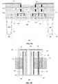
- An arrangement for a larger semiconductor device 400 is shown in cross-section in figure 6A and plan view in figure 6B .
- Figure 6A shows a cross-section of the semiconductor device 400 according to an embodiment including a number of layers formed on and in a substrate 402.
- Semiconductor device 400 may include a buried N-well region 410 formed in the substrate and between trenches 404. P-well stopper regions 406 may be formed beneath the trenches 404.
- An epitaxial N-type layer 412 may be formed above the buried N-well 410.
- N+ regions 414, 418' may be formed within the same layer and may extend from above the surface of the substrate 402 to the buried N-well 410.
- the N+ region 414, part of the buried N-well 410 and part of the epitaxial region 412 may form the collector of the common-emitter NPN transistor 162.
- the N+ region 418', part of the buried N-well 410 and part of the epitaxial region 412 may form the emitter of the common-base NPN transistor 164 which for semiconductor device 400 is implemented as two sections 164_1,
- the silicon germanium base regions 416, 416' are formed above the N+ regions 414, 418'.
- An N-type emitter 418 is formed above the base 416.
- An N-type collector 414' is formed above the base 416'.
- Collector contacts 420 are formed on N+ regions 414' .
- Base contacts 422, 422' are formed on the base region 416.
- Emitter contact 424 is formed on the emitter region 418.
- the regions 426 indicate areas of dielectric material.
- the respective collector regions for common emitter stage 162 and emitter regions 418' for common base stage 164 may be formed on the same layer of the semiconductor device 400.
- the respective base regions 416 and 416' may be formed on the same layer of the semiconductor device 400.
- the emitter region 418 for common emitter stage 162 and collector region 414' for the common base stage 164 are formed on the same layer of the semiconductor device 400.
- the semiconductor device 400 has three metal layers respectively 452, 454, and 456 which are separated by layers containing dielectric material 426. Vias 458 are used to connect between the different metal layers and to connect the first metal layer 452 to the contacts 422,424 of the common emitter transistor 162 and contacts 420, 422' of the common emitter transistor 164.
- the ground rail 154 is connected by the third layer metal 456 to the emitter contact 424 via contacts 460 down through the second metal layer 454 and the first metal layer 452.
- Contacts 462 illustrate either contacts between the second metal layer 454 and the first metal layer 452 or the first metal layer 454 and the active area contacts.
- the common emitter transistor 162 of semiconductor device 400 as illustrated shows a single emitter finger. In other examples common emitter stages may have transistors with more emitter fingers. The transistors may be implemented in sections containing one or more emitter finger.
- the common base transistor 164 of semiconductor device 400 as illustrated is implemented in two sections 164_1, 164_2 each section having one emitter finger.
- the RF input 158 connects to the base of the common emitter transistor 162.
- RF output 166 as shown is implemented on the third metal layer 456 and connects to the collector contact 420 of the common base transistor 164 using vias 458 down through the second metal layer 454 and the first metal layer 452.
- the inter-stage connection 160 is effectively formed in the common region of the buried-N layer 410.
- the semiconductor device 400 has a common emitter stage 162 with a single common emitter section a common base stage 164 with two common base sections 164_1, 164_2 on top of the same shared buried-N layer 410.
- the common emitter stage may have multiple sections alternating with multiple common base sections depending on the size of the device required.
- the size ratio between CE transistor 162 and CB transistor 164 may be modified by for example having different section sizes, varying the number of emitter-fingers per section, or varying the length of the emitter-fingers independently for the CE transistor 162 and the CB transistor 164.
- This semiconductor device 400 may have a smaller foot-print than semiconductor device 250 requiring reduced silicon area to implement.
- the semiconductor device 400 may have reduced inter-stage loss, due to reduced connection resistance because no metal interconnect is required and no contact/Deep-N plug is required.
- the semiconductor device 400 may further have reduced parasitic substrate capacitance but requires no additional processing compared to known techniques.
- the emitter-base junction of the common-base transistor 164 may have a reverse breakdown voltage of the normal mode emitter-base junction which is usually significantly lower than that of the collector-base diode.
- the common base transistor 162 of the semiconductor devices 300,400 may be further adapted using techniques described for example in European Patent 2784822 , US patent 9240468 B2 which may require some additional processing steps.
- FIG. 7A An embodiment of a semiconductor device including one of these techniques is shown in figures 7A and 7B .
- Figure 7A shows a cross-section of the semiconductor device 500 according to an embodiment including a number of layers formed on and in a substrate 502.
- Semiconductor device 500 may include a buried N-well region 510 formed in the substrate and between trenches 504. P-well stopper regions 506 may be formed beneath the trenches 504.
- An epitaxial N-type layer 512 may be formed above the buried N-well 510.
- N+ regions 514, 518' may be formed within the same layer and may extend from above the surface of the substrate 502 to the buried N-well 510.
- the N+ region 514, part of the buried N-well 510 and part of the epitaxial region 512 may form the collector of the common-emitter NPN transistor 162.
- the N+ region 518', part of the buried N-well 510 and part of the epitaxial region 512 may form the emitter of the common-base NPN transistor 164 which in semiconductor device 500 is implemented as two sections 164_1, 164_
- the silicon germanium base regions 516, 516' are formed above the N+ regions 514, 518'.
- An N-type emitter 518 is formed above the base 516.
- An N-type collector 514' is formed above the base 516'. The collector 514' extends laterally beyond the base.
- Collector contacts 520 are formed on N+ regions 514' .
- Base contacts 522, 522' are formed on the base regions 516, 516'.
- Emitter contact 524 is formed on the emitter region 518.
- the regions 526 indicate areas of dielectric material.
- the respective collector regions for common emitter stage 162 and emitter regions 518' for common base stage 164 may be formed on the same layer of the semiconductor device 500.
- the respective base regions 516 and 516' may be formed on the same layer of the semiconductor device 500.
- the emitter region 518 for common emitter stage 162 and collector region 514' for the common base stage 164 are formed on the same layer of the semiconductor device 500.
- the semiconductor device 500 has three metal layers respectively 552, 554, and 556 which are separated by layers containing dielectric material 526. Vias 558 are used to connect between the different metal layers and to connect the first metal layer 552 to the contacts 522,524 of the common emitter transistor 162 and contacts 520, 522' of the common emitter transistor 164.
- the common emitter transistor 162 of semiconductor device 500 as illustrated shows a single emitter finger. In other examples common emitter stages may have transistors with more emitter fingers. The transistors may be implemented in sections containing one or more emitter finger.
- the common base transistor 164 of semiconductor device 500 as illustrated is implemented in two sections 164_1, 164_2 each section having one emitter finger.
- the RF input 158 connects to the base of the common emitter transistor 162.
- RF output 166 as shown is implemented on the third metal layer 556 and connects to the collector contact 520 of the common base transistor 164 using vias 558 down through the second metal layer 554 and the first metal layer 552.
- the inter-stage connection 160 is effectively formed in the common region of the buried-N layer 510.
- the Semiconductor device 500 has a common emitter stage 162 with a single common emitter section a common base stage 164 with two common base sections 164_1, 164_2 on top of the same shared buried-N layer 510.
- the common emitter stage may have multiple sections alternating with multiple common base sections depending on the size of the device required.
- the ratio between CE transistor 162 and CB transistor size 164 may be modified by different section sizes for both, by modifying the number of emitter-fingers per section, as well as varying the length of the emitter-fingers independently for the CE transistor 162 and the CB transistor 164.
- This semiconductor device 500 may have a smaller foot-print than semiconductor device 250 requiring reduced silicon area to implement.
- the semiconductor device 500 may have reduced inter-stage loss, due to reduced connection resistance because no metal interconnect is required and no contact/Deep-N plug is required.
- the semiconductor device 500 may further have reduced parasitic substrate capacitance.
- the semiconductor device 500 has a common base transistor 164 with a collector region 514' that extends laterally beyond the base. This may result in a higher breakdown voltage for the collector-base junction of the common base transistor 164 as explained in US9240468 B2 which may allow the semiconductor device 500 to operate at higher power.
- the semiconductor device may include a gate formed on the collector 514' of the common base transistor to modulate the electric field instead or as well as a collector 514' laterally extending beyond the base. This may further improve the breakdown voltage characteristics of the collector-base junction of the common-base transistor 164.
- a semiconductor device including a substrate and a plurality of layers.
- the semiconductor device includes a cascode arrangement of a first bipolar transistor and a second bipolar transistor.
- a first-bipolar-transistor-collector of the first bipolar transistor and a second-bipolar-transistor-emitter of the second bipolar transistor are at least partially located in a common region in the same layer of the semiconductor device.
- Embodiments of a semiconductor device include an integrated cascode (CE-CB-stage) device.
- the collector of the common-emitter transistor and the emitter of the common-base transistor are formed in a common region. Consequently, the collector of the common-emitter transistor device also acts as the emitter of the common-base transistor device, which eliminates the need for inter-stage matching and may reduce the device area. As a result, the overall losses due to parasitic resistances and/or capacitances may be significantly reduced, improving the RF performance of an amplifier including the integrated cascode.
- Embodiments of the cascode semiconductor device may use the same layers for forming both the common-base stage and common emitter stage and so are suitable for inclusion on an integrated circuit.
- the common base transistor and common emitter transistor may be vertical HBTs formed side-by-side. Because both CE and CB stages are in contact with the substrate, the thermal performance may be improved.
- the illustrated embodiments show NPN bipolar transistors implementing a cascode of a common emitter stage and a common base stage for an RF amplifier. In other embodiments a cascode of two NPN transistors may be used for other applications. It will be further appreciated from the present disclosure that other embodiments of a cascode may be implemented using PNP bipolar transistors.
- Embodiments of the integrated cascode may be included in RF power amplifier or RF low noise amplifiers. Embodiments may be included in RF amplifiers operating at frequencies may above 20 GHz which are used for example in 5G mobile communications applications.
Abstract
A semiconductor device is described including a substrate (302) and a plurality of layers. The semiconductor device includes a cascode arrangement of a first bipolar transistor (162) and a second bipolar transistor (164). A first-bipolar-transistor-collector of the first bipolar transistor and a second-bipolar-transistor-emitter of the second bipolar transistor are at least partially located in a common region (310) in the same layer of the semiconductor device.
Description
- This disclosure relates to a semiconductor device including a cascode arrangement of a first bipolar transistor and a second bipolar transistor.
- Radio-frequency (RF) amplifier circuits are often implemented using BiCMOS processes as, although CMOS based technologies may be used to implement RF amplifiers, bipolar transistors may provide more optimal performance for certain power levels and operation frequencies. These bipolar transistors are often implemented in several sections with finger-like transistor shapes. The bipolar transistors may be implemented as heterojunction bipolar transistors (HBT) for example using Silicon-Germanium (Si-Ge) BiCMOS processes. HBTs implemented using Si-Ge BiCMOS processes may have good performance characteristics in higher frequency ranges above 20 GHz which are used for example in 5G mobile communications applications. RF amplifiers implemented using BiCMOS processes may be used for example as power amplifiers which receive a signal for transmission from a transceiver and drive an antenna or low noise amplifiers which receive a signal from an antenna and output the received signal to the transceiver.
- RF amplifiers implemented using bipolar transistors may include a cascode stage having a cascode arrangement of a common-emitter (CE) stage including one or more bipolar transistors in a common-emitter configuration and a common-base (CB) stage including one or more bipolar transistors in a common-base configuration. A common-emitter/common-base cascode stage is a frequently used amplifier stage, both in Power Amplifier (PA) and in Low Noise Amplifier (LNA) circuits, offering high gain, high bandwidth, high slew rate, high stability, and high input impedance.
- Various aspects of the disclosure are defined in the accompanying claims. In a first aspect there is provided a semiconductor device comprising a substrate, a plurality of layers located on or in the substrate and a lateral cascode arrangement of a first bipolar transistor and a second bipolar transistor, wherein the first bipolar transistor comprises a first-bipolar-transistor-collector, the second bipolar transistor comprises a second-bipolar-transistor-emitter, and wherein the first-bipolar-transistor-collector and the second-bipolar-transistor-emitter are at least partially located in a common region in one layer of said plurality of layers.
- In one or more example embodiments, the first bipolar transistor further may comprise a first-bipolar-transistor-base located above the first-bipolar-transistor-collector and a first-bipolar-transistor-emitter located above the first-bipolar-transistor-base and the second bipolar transistor comprises a second-bipolar-transistor-base located above the second-bipolar-transistor-emitter and a second-bipolar-transistor-collector located above the second-bipolar-transistor-base.
- In one or more example embodiments, the common region may comprise a buried N type layer.
- In one or more example embodiments, the first and second bipolar transistors may be NPN transistors.
- In one or more example embodiments, the common region the common region may be located between two trenches.
- In one or more example embodiments, the semiconductor device may comprise a common emitter stage comprising the first bipolar transistor and a common base stage comprising the second bipolar transistor.
- In one or more example embodiments, the second-bipolar-transistor-collector may include a portion extending laterally past an edge of the second-bipolar-transistor-base.
- In one or more example embodiments, the second-bipolar-transistor-collector may comprise a collector gate.
- In one or more example embodiments, the first bipolar transistor emitter and second bipolar transistor emitter further comprise at least one emitter finger.
- In one or more example embodiments, the first bipolar transistor may comprise at least one section located above the common region and the second bipolar transistor may comprise at least two sections located above the common region and wherein the each section of the at least one first bipolar transistor section is arranged alternately with each section of the at least two second bipolar transistor sections.
- In one or more example embodiments, the semiconductor device may further comprise an input coupled to the first bipolar transistor base, an output coupled to the second bipolar transistor collector, a supply rail coupled to the second bipolar transistor collector, a ground rail coupled to the first bipolar transistor emitter, and a second bipolar transistor base is coupled to a bias voltage rail.
- In one or more example embodiments, the first bipolar transistor base and the second bipolar transistor base may be located in the same layer.
- In one or more example embodiments, the first bipolar transistor emitter and the second bipolar transistor collector are at least partially located in the same layer.
- In one or more example embodiments, the semiconductor device may be a silicon-germanium BiCMOS device.
- Embodiments of the semiconductor device may be included in an RF amplifier.
- In a second aspect there is provided a semiconductor device having a plurality of layers and comprising a substrate, and a cascode arrangement of a first bipolar transistor in a common emitter configuration and a second bipolar transistor in a common-base configuration, wherein a first-bipolar-transistor-collector and a second-bipolar-transistor-emitter are at least partially located in a common region of the semiconductor device and wherein a first-bipolar-transistor-base is located in the same layer as the second-bipolar-transistor-base.
- In the figures and description like reference numerals refer to like features. Embodiments are now described in detail, by way of example only, illustrated by the accompanying drawings in which:
-
Figure 1 Shows a circuit diagram of a typical RF low noise amplifier. -
Figure 2 Shows a circuit diagram of a cascode stage for an RF amplifier using NPN bipolar transistors. -
Figure 3 Show a cross-section of a typical NPN HBT bipolar transistor implemented using a Si-Ge BiCMOS process. -
Figure 4A illustrates a cross-section of a typical implementation of the cascode stage offigure 2 using a Si-Ge BiCMOS process. -
Figure 4B illustrates the plan view of the cascode stage implementation offigure 4A . -
Figure 5A illustrates a cross-section of an implementation of the cascode stage offigure 2 using a Si-Ge BiCMOS process according to an embodiment. -
Figure 5B illustrates the plan view of the cascode stage implementation offigure 5A according to an embodiment. -
Figure 6A illustrates a cross section of an implementation of the cascode stage offigure 2 using a Si-Ge BiCMOS process according to an embodiment. -
Figure 6B illustrates the plan view of the cascode stage implementation offigure 6A according to an embodiment. -
Figure 7A illustrates a cross section of an implementation of the cascode stage offigure 2 using a Si-Ge BiCMOS process according to an embodiment. -
Figure 7B illustrates the plan view of the cascode stage implementation offigure 7A according to an embodiment. -
Figure 1 shows a circuit diagram of a typical RF low noise amplifier (LNA) 100 implemented using NPN bipolar transistors. LNA 100 has acascode input stage 110 including a common emitter (CE) NPN transistor Q1 and a common base (CB) transistor Q2. Thelow noise amplifier 100 has a second amplifier stage including a NPN transistor Q3 configured as a common emitter transistor. AnRF input 108 is connected in series via input inductor Lin to the base of common emitter transistor Q1. A series arrangement of a tank inductor Lt and a tank capacitor Ct is connected between the base of the common emitter transistor Q1 andground 104. The emitter of common emitter transistor Q1 is connected toground 104 via the Q1 emitter degeneration inductor Ldeg. The collector of the common emitter transistor Q1 is connected to the emitter of the common base transistor Q2 via inter-stage matching inductor LMID. - The base of the common base transistor Q2 is connected to
ground 104 via capacitor C12. The base of the common base transistor Q2 is connected to a bias circuit (not shown). The collector of common base transistor Q2 is connected to a firststage supply rail 102 via first stage output inductor Lo1. An output matching network including a series arrangement of a first stage matching capacitor C11 and a first stage matching inductor L11 is connected between the collector of the common base transistor Q2 and the base of the second stage common emitter transistor Q3. The emitter of the second stage common emitter transistor Q3 is connected toground 104 via the Q3 emitter degeneration inductor Ldeg2. The collector of the second stage common emitter transistor Q3 is connected to the second stage supply rail 102' via the second stage output inductor Lo2. The collector of the second stage common emitter transistor Q3 is connected to theRF output 106 via the second stage output matching network. The second stage output matching network includes a series arrangement of a matching network inductor L21 and a matching network capacitor C22 between the collector of the second stage common emitter transistor Q3 and theRF output 106. The second stage output matching network includes a second matching network capacitor C21 connected between thecommon node 112 of the matching network inductor L21 and capacitor C22 andground 104. - The
low noise amplifier 100 receives an RF signal on theRF input 108 which goes to the base of the common emitter transistor Q1. The output of thecascode stage 110 is at the collector of the common base transistor Q2 which then goes to the base of the common emitter transistor Q3 of the second stage. The output of the second stage is at the collector of the common emitter transistor Q3. The signal then goes to theRF output 106 of thelow noise amplifier 100. Thelow noise amplifier 100 requires an inductor LMID which needs to be added to have a proper impedance match between the collector of the common emitter transistor Q1 and the emitter of the common base transistor Q2. This inductor LMID may create losses in thelow noise amplifier 100 and also require additional area for implementation. -
Figure 2 illustrates the circuit diagram of acascode 150 for an RF amplifier which may be implemented by the various examples and embodiments described herein. Thecommon emitter stage 162 may include a first bipolarNPN transistor Q 1 having a first-bipolar-transistor-emitter connected to aground rail 154, a first-bipolar-transistor-base connected to anRF input 158 and a first-bipolar-transistor-collector connected to theinter-stage connection 160. Thecommon base stage 164 may include a second NPN bipolar transistor Q2 having a second-bipolar-transistor-emitter connected to theinter-stage connection 160, a second-bipolar-transistor-base operably connected to abias voltage supply 156, and a second-bipolar-transistor-collector connected to anRF output 166. The connection from the collector of the common base transistor Q2 to the supply voltage via an inductor is not shown. -
Figure 3 schematically illustrates a cross-section of a verticalNPN HBT transistor 200 known in the art implemented using a silicon germanium (SiGe) BiCMOS process. Thetransistor 200 may be particularly suitable for high frequency RF applications. Thetransistor 200 includes a number of layers formed on and in asubstrate 202. It will be appreciated thattransistor 200 may be formed using standard front-end of the line (FEOL) processing techniques. - The
HBT transistor 200 may includetrenches 204 formed in thesubstrate 202 from intrinsic and P-type stopper regions 206 may be formed at the bottom of thetrenches 204. Thetransistor 200 may include a buried N-well region 210 formed in the substrate and between thetrenches 204. An epitaxial N-type layer 212 may be formed between the surface of the substrate and the buried N-well 210. Deep-N plugs 208 may be formed which extend from above the major surface of thesubstrate 202 down to within the buried N-well 210. AnN+ region 214 may be formed which extends from above the surface of thesubstrate 202 to the buried N-well 210. The term N+ is used herein has the usual meaning of an N type semiconductor region with relatively high dopant concentration. The Deep-N plugs 208,N+ region 214, the buried N-well 210 and theepitaxial region 212 may form the collector of theNPN transistor 200. Abase region 216 is formed above theN+ region 214 from a layer of silicon germanium. An N-type emitter 218 is formed above thebase 216.Collector contacts 220 are formed on the Deep-N plugs 208.Base contacts 222 are formed on thebase region 216.Emitter contact 224 is formed on theemitter region 218.Collector contacts 220,base contacts 222,emitter contacts 224 may be formed from polysilicon. Theregions 226 indicate areas of dielectric material, however it will be appreciated that dielectric material will also be present in other layers but this is not shown explicitly infigure 3 . It will be appreciated thattransistor 200 may be formed using standard front-end of the line (FEOL) processing techniques. -
Figure 4A Shows asemiconductor device 250 which implements thecascode stage 150 offigure 2 using HBT NPN transistors similar totransistor 200.Figure 4B Illustrates the plan view of thesemiconductor device 250. - The common
emitter stage transistor 162 has a collector formed by the buried N well 210, the deepN plug regions 208 theepitaxial region 212 and the N plusregion 214 as described previously forfigure 3 . The commonemitter stage transistor 162 has a base 216 formed above the collector. The commonemitter stage transistor 162 has anemitter region 218 formed above thebase 216.Trenches 204 and P-wellstoppers 206 isolate thetransistor 162 from thecommon base transistor 164.Collector contacts 220 are formed on the deep N plugs 208.Base contacts 222 are formed on thebase region 216.Emitter contacts 224, are formed on theemitter region 218. - The common
base stage transistor 164 has a collector formed by the buried N well 210', the deep N plug regions 208' the epitaxial region 212' and the N plus region 214' similarly to as described previously fortransistor 200 illustrated infigure 3 . The commonbase stage transistor 164 has a base 216' formed above the collector. The commonbase stage transistor 164 has emitter regions 218' formed above the base 216'. Trenches 204' and P-well stoppers 206' isolate thecommon base transistor 164 from thecommon emitter transistor 162. Collector contacts 220' are formed on the deep N plugs 208'. Base contacts 222' are formed on the base region 216'.Emitter contacts 224, are formed on the emitter region 218'. - The common
base stage transistor 164 and thecommon emitter transistor 162 are arranged laterally along a horizontal axis. In this disclosure the horizontal axis refers to an axis parallel to a major surface of thesubstrate 202. - The
respective collector regions 214 and 214' are formed on the same layer of thesemiconductor device 250. Therespective base regions 216 and 216' are formed on the same layer of thesemiconductor device 250. Therespective emitter regions 218 and 218' are formed on the same layer of thesemiconductor device 250. - The
semiconductor device 250 has three metal layers respectively 252,254, and 256 which are separated by layers containingdielectric material 226.Vias 258 are used to connect between the different metal layers and to connect thefirst metal layer 252 to the contacts 220,222,224 of thecommon emitter transistor 162 and contacts 220',222',224' of thecommon base transistor 164. - Turning now to
figure 4B , theground rail 154 is connected by thethird layer metal 256 to theemitter contact 224 viacontacts 260 down through thesecond metal layer 254 and thefirst metal layer 252.Contacts 262 illustrate either contacts between thesecond metal layer 254 and thefirst metal layer 252 or thefirst metal layer 254 and the transistor contacts. Thecommon emitter transistor 162 ofsemiconductor device 250 as illustrated shows a single emitter finger. Thecommon base transistor 164 ofsemiconductor device 250 as illustrated shows two emitter fingers. - The
RF input 158 connects to the base of thecommon emitter transistor 162. Theinter-stage connection 160 is shown as a straight metal connection on thethird metal layer 256 which implements the inductor LMID. RF output 166 as shown is implemented on thethird metal layer 256 and connects to the collector contact 220' of thecommon base transistor 164 usingvias 258 down through thesecond metal layer 254 and thefirst metal layer 252. This inductor LMID may create losses in the cascode and also requires additional area for implementation. - The
semiconductor device 200 as shown has six pin connections which are connected via the metal layers 252,254,256 denoted as common-emitter base (CEB), common-emitter emitter (CEE), common-emitter collector (CEC), common-base base (CBB), common-base emitter (CBE), common base collector (CBC). -
Figure 5A shows asemiconductor device 300 which implements thecascode stage 150 offigure 2 according to an embodiment.Figure 5B illustrates the plan view of thesemiconductor device 300. - The
semiconductor device 300 includes a number of layers which may be formed on or in asubstrate 302.Semiconductor device 300 may include a buried N-well region 310 formed in the substrate and betweentrenches 304. P-well stopper regions 306 may be formed beneath thetrenches 304. An epitaxial N-type layer 312 may be formed above the buried N-well 310.N+ regions 314, 318' may be formed within the same layer and may extend from above the surface of thesubstrate 302 to the buried N-well 310. TheN+ region 314, part of the buried N-well 310 and part of theepitaxial region 312 may form the collector of the common-emitter NPN transistor 164. The N+ region 318', part of the buried N-well 310 and part of theepitaxial region 312 may form the emitter of the common-base NPN transistor 162. - The silicon
germanium base regions 316, 316' are formed above theN+ regions 314, 318'. An N-type emitter 318 is formed above thebase 316. An N-type collector 314' is formed above the base 316'.Collector contacts 320 are formed on N+ regions 314' .Base contacts 322, 322' are formed on thebase region 316.Emitter contact 324 is formed on theemitter region 318. Theregions 326 indicate areas of dielectric material. - The respective collector regions for
common emitter stage 162 and emitter regions 318' forcommon base stage 164 may be formed on the same layer of thesemiconductor device 300. Therespective base regions 316 and 316' may be formed on the same layer of thesemiconductor device 300. Theemitter region 318 forcommon emitter stage 162 and collector region 314' for thecommon base stage 164 are formed on the same layer of thesemiconductor device 300. The first bipolar transistor Q1 of thecommon emitter stage 162 and the second bipolar transistor Q2 of thecommon base stage 164 may be located in the same horizontal plane. - The
semiconductor device 300 has three metal layers respectively 352, 354, and 356 which are separated by layers containingdielectric material 326.Vias 358 are used to connect between the different metal layers and to connect thefirst metal layer 352 to the contacts 322,324 of thecommon emitter transistor 162 andcontacts 320, 322' of thecommon emitter transistor 164. - Turning now to
figure 5B , theground rail 154 is connected by thethird layer metal 356 to theemitter contact 324 viacontacts 360 down through thesecond metal layer 354 and thefirst metal layer 352.Contacts 362 illustrate either contacts between thesecond metal layer 354 and thefirst metal layer 352 or thefirst metal layer 354 and the active area contacts. Thecommon emitter transistor 162 ofsemiconductor device 300 as illustrated shows a single emitter finger. In other examples common emitter stages may have transistors with more emitter fingers. The transistors may be implemented in sections containing one or more emitter finger. Thecommon base transistor 164 ofsemiconductor device 300 as illustrated shows a single section with two emitter fingers. - The
RF input 158 connects to the base of thecommon emitter transistor 162.RF output 166 as shown is implemented on thethird metal layer 356 and connects to thecollector contact 320 of thecommon base transistor 164 usingvias 358 down through thesecond metal layer 354 and thefirst metal layer 352. Theinter-stage connection 160 is effectively formed in the common region of the buried-N layer 310 - The inventors of the present disclosure have appreciated that in a modern, high-speed, SiGe BiCMOS process, the collector-base profile is as steep as the emitter-base profile. Consequently the transistors formed by such a process can be configured either with the emitter or collector located at the top. When a device is configured in an "inverse mode" (collector on top) the performance of the device may be similar. By using an inverse-mode transistor for the
CB transistor 164, the emitter may be at least partially created in the same device layer, for example the buried N-layer 310, as the collector of theCE transistor 162. Hence, instead of making the connection between both transistors 162,164 via the back-end interconnect, the connection can be made on a common region, in this case a shared buried-N island 310, thereby creating a singleintegrated cascode device 300. Thissemiconductor device 300 has 4 pins, CEE, CEB, CBB and CBC, missing the CEC and CBE from the conventional implementation of thesemiconductor device 250. - This
semiconductor device 300 may have a smaller foot-print thansemiconductor device 250 requiring reduced silicon area to implement. Thesemiconductor device 300 may have reduced inter-stage loss, due to reduced connection resistance because no metal interconnect is required and no contact/Deep-N plug is required. Thesemiconductor device 300 may further have reduced parasitic substrate capacitance but requires no additional processing compared to known techniques. Further thesemiconductor device 300 does not need a Deep-N plug, to connect to the buried-N 310. In some examples the buried-N region 310 may also be omitted and theepilayer 312 used as a common region to form the interconnection. - The
semiconductor device 300 may be used for a relatively small device, consisting of only a few emitter-fingers. An arrangement for alarger semiconductor device 400 is shown in cross-section infigure 6A and plan view infigure 6B . -
Figure 6A shows a cross-section of thesemiconductor device 400 according to an embodiment including a number of layers formed on and in asubstrate 402.Semiconductor device 400 may include a buried N-well region 410 formed in the substrate and betweentrenches 404. P-well stopper regions 406 may be formed beneath thetrenches 404. An epitaxial N-type layer 412 may be formed above the buried N-well 410.N+ regions 414, 418'may be formed within the same layer and may extend from above the surface of thesubstrate 402 to the buried N-well 410. TheN+ region 414, part of the buried N-well 410 and part of theepitaxial region 412 may form the collector of the common-emitter NPN transistor 162. The N+ region 418', part of the buried N-well 410 and part of theepitaxial region 412 may form the emitter of the common-base NPN transistor 164 which forsemiconductor device 400 is implemented as two sections 164_1, 164_2. - The silicon
germanium base regions 416, 416' are formed above theN+ regions 414, 418'. An N-type emitter 418 is formed above thebase 416. An N-type collector 414' is formed above the base 416'. Collector contacts 420 are formed on N+ regions 414' .Base contacts 422, 422' are formed on thebase region 416.Emitter contact 424 is formed on theemitter region 418. Theregions 426 indicate areas of dielectric material. - The respective collector regions for
common emitter stage 162 and emitter regions 418' forcommon base stage 164 may be formed on the same layer of thesemiconductor device 400. Therespective base regions 416 and 416' may be formed on the same layer of thesemiconductor device 400. Theemitter region 418 forcommon emitter stage 162 and collector region 414' for thecommon base stage 164 are formed on the same layer of thesemiconductor device 400. - The
semiconductor device 400 has three metal layers respectively 452, 454, and 456 which are separated by layers containingdielectric material 426. Vias 458 are used to connect between the different metal layers and to connect thefirst metal layer 452 to the contacts 422,424 of thecommon emitter transistor 162 and contacts 420, 422' of thecommon emitter transistor 164. - Turning now to
figure 6B , theground rail 154 is connected by the third layer metal 456 to theemitter contact 424 viacontacts 460 down through thesecond metal layer 454 and thefirst metal layer 452.Contacts 462 illustrate either contacts between thesecond metal layer 454 and thefirst metal layer 452 or thefirst metal layer 454 and the active area contacts. Thecommon emitter transistor 162 ofsemiconductor device 400 as illustrated shows a single emitter finger. In other examples common emitter stages may have transistors with more emitter fingers. The transistors may be implemented in sections containing one or more emitter finger. Thecommon base transistor 164 ofsemiconductor device 400 as illustrated is implemented in two sections 164_1, 164_2 each section having one emitter finger. - The
RF input 158 connects to the base of thecommon emitter transistor 162.RF output 166 as shown is implemented on the third metal layer 456 and connects to the collector contact 420 of thecommon base transistor 164 using vias 458 down through thesecond metal layer 454 and thefirst metal layer 452. Theinter-stage connection 160 is effectively formed in the common region of the buried-N layer 410. - The
semiconductor device 400 has acommon emitter stage 162 with a single common emitter section acommon base stage 164 with two common base sections 164_1, 164_2 on top of the same shared buried-N layer 410. In other examples the common emitter stage may have multiple sections alternating with multiple common base sections depending on the size of the device required. The size ratio betweenCE transistor 162 andCB transistor 164 may be modified by for example having different section sizes, varying the number of emitter-fingers per section, or varying the length of the emitter-fingers independently for theCE transistor 162 and theCB transistor 164. - This
semiconductor device 400 may have a smaller foot-print thansemiconductor device 250 requiring reduced silicon area to implement. Thesemiconductor device 400 may have reduced inter-stage loss, due to reduced connection resistance because no metal interconnect is required and no contact/Deep-N plug is required. Thesemiconductor device 400 may further have reduced parasitic substrate capacitance but requires no additional processing compared to known techniques. - In semiconductor devices 300,400 the emitter-base junction of the common-
base transistor 164 may have a reverse breakdown voltage of the normal mode emitter-base junction which is usually significantly lower than that of the collector-base diode. For higher power devices thecommon base transistor 162 of the semiconductor devices 300,400 may be further adapted using techniques described for example in European Patent2784822 ,US patent 9240468 B2 - An embodiment of a semiconductor device including one of these techniques is shown in
figures 7A and 7B . -
Figure 7A shows a cross-section of thesemiconductor device 500 according to an embodiment including a number of layers formed on and in asubstrate 502.Semiconductor device 500 may include a buried N-well region 510 formed in the substrate and betweentrenches 504. P-well stopper regions 506 may be formed beneath thetrenches 504. An epitaxial N-type layer 512 may be formed above the buried N-well 510.N+ regions 514, 518' may be formed within the same layer and may extend from above the surface of thesubstrate 502 to the buried N-well 510. TheN+ region 514, part of the buried N-well 510 and part of theepitaxial region 512 may form the collector of the common-emitter NPN transistor 162. The N+ region 518', part of the buried N-well 510 and part of theepitaxial region 512 may form the emitter of the common-base NPN transistor 164 which insemiconductor device 500 is implemented as two sections 164_1, 164_2. - The silicon
germanium base regions 516, 516' are formed above theN+ regions 514, 518'. An N-type emitter 518 is formed above thebase 516. An N-type collector 514' is formed above the base 516'. The collector 514' extends laterally beyond the base.Collector contacts 520 are formed on N+ regions 514' .Base contacts 522, 522' are formed on thebase regions 516, 516'.Emitter contact 524 is formed on theemitter region 518. Theregions 526 indicate areas of dielectric material. - The respective collector regions for
common emitter stage 162 and emitter regions 518' forcommon base stage 164 may be formed on the same layer of thesemiconductor device 500. Therespective base regions 516 and 516' may be formed on the same layer of thesemiconductor device 500. Theemitter region 518 forcommon emitter stage 162 and collector region 514' for thecommon base stage 164 are formed on the same layer of thesemiconductor device 500. - The
semiconductor device 500 has three metal layers respectively 552, 554, and 556 which are separated by layers containingdielectric material 526.Vias 558 are used to connect between the different metal layers and to connect thefirst metal layer 552 to the contacts 522,524 of thecommon emitter transistor 162 andcontacts 520, 522' of thecommon emitter transistor 164. - Turning now to
figure 7B , theground rail 154 is connected by thethird layer metal 556 to theemitter contact 524 viacontacts 560 down through thesecond metal layer 554 and thefirst metal layer 552.Contacts 562 illustrate either contacts between thesecond metal layer 554 and thefirst metal layer 552 or thefirst metal layer 554 and the active area contacts. Thecommon emitter transistor 162 ofsemiconductor device 500 as illustrated shows a single emitter finger. In other examples common emitter stages may have transistors with more emitter fingers. The transistors may be implemented in sections containing one or more emitter finger. Thecommon base transistor 164 ofsemiconductor device 500 as illustrated is implemented in two sections 164_1, 164_2 each section having one emitter finger. - The
RF input 158 connects to the base of thecommon emitter transistor 162.RF output 166 as shown is implemented on thethird metal layer 556 and connects to thecollector contact 520 of thecommon base transistor 164 usingvias 558 down through thesecond metal layer 554 and thefirst metal layer 552. Theinter-stage connection 160 is effectively formed in the common region of the buried-N layer 510. - The
Semiconductor device 500 has acommon emitter stage 162 with a single common emitter section acommon base stage 164 with two common base sections 164_1, 164_2 on top of the same shared buried-N layer 510. In other examples the common emitter stage may have multiple sections alternating with multiple common base sections depending on the size of the device required. The ratio betweenCE transistor 162 andCB transistor size 164 may be modified by different section sizes for both, by modifying the number of emitter-fingers per section, as well as varying the length of the emitter-fingers independently for theCE transistor 162 and theCB transistor 164. - This
semiconductor device 500 may have a smaller foot-print thansemiconductor device 250 requiring reduced silicon area to implement. Thesemiconductor device 500 may have reduced inter-stage loss, due to reduced connection resistance because no metal interconnect is required and no contact/Deep-N plug is required. Thesemiconductor device 500 may further have reduced parasitic substrate capacitance. Thesemiconductor device 500 has acommon base transistor 164 with a collector region 514' that extends laterally beyond the base. This may result in a higher breakdown voltage for the collector-base junction of thecommon base transistor 164 as explained inUS9240468 B2 semiconductor device 500 to operate at higher power. In other embodiments the semiconductor device may include a gate formed on the collector 514' of the common base transistor to modulate the electric field instead or as well as a collector 514' laterally extending beyond the base. This may further improve the breakdown voltage characteristics of the collector-base junction of the common-base transistor 164. - A semiconductor device is described including a substrate and a plurality of layers. The semiconductor device includes a cascode arrangement of a first bipolar transistor and a second bipolar transistor. A first-bipolar-transistor-collector of the first bipolar transistor and a second-bipolar-transistor-emitter of the second bipolar transistor are at least partially located in a common region in the same layer of the semiconductor device.
- Embodiments of a semiconductor device include an integrated cascode (CE-CB-stage) device. The collector of the common-emitter transistor and the emitter of the common-base transistor are formed in a common region. Consequently, the collector of the common-emitter transistor device also acts as the emitter of the common-base transistor device, which eliminates the need for inter-stage matching and may reduce the device area. As a result, the overall losses due to parasitic resistances and/or capacitances may be significantly reduced, improving the RF performance of an amplifier including the integrated cascode. Embodiments of the cascode semiconductor device may use the same layers for forming both the common-base stage and common emitter stage and so are suitable for inclusion on an integrated circuit. The common base transistor and common emitter transistor may be vertical HBTs formed side-by-side. Because both CE and CB stages are in contact with the substrate, the thermal performance may be improved. The illustrated embodiments show NPN bipolar transistors implementing a cascode of a common emitter stage and a common base stage for an RF amplifier. In other embodiments a cascode of two NPN transistors may be used for other applications. It will be further appreciated from the present disclosure that other embodiments of a cascode may be implemented using PNP bipolar transistors.
- Embodiments of the integrated cascode may be included in RF power amplifier or RF low noise amplifiers. Embodiments may be included in RF amplifiers operating at frequencies may above 20 GHz which are used for example in 5G mobile communications applications.
- Although the appended claims are directed to particular combinations of features, it should be understood that the scope of the disclosure of the present invention also includes any novel feature or any novel combination of features disclosed herein either explicitly or implicitly or any generalisation thereof, whether or not it relates to the same invention as presently claimed in any claim and whether or not it mitigates any or all of the same technical problems as does the present invention.
- Features which are described in the context of separate embodiments may also be provided in combination in a single embodiment. Conversely, various features which are, for brevity, described in the context of a single embodiment, may also be provided separately or in any suitable sub combination.
- The applicant hereby gives notice that new claims may be formulated to such features and/or combinations of such features during the prosecution of the present application or of any further application derived therefrom.
- For the sake of completeness it is also stated that the term "comprising" does not exclude other elements or steps, the term "a" or "an" does not exclude a plurality, a single processor or other unit may fulfil the functions of several means recited in the claims and reference signs in the claims shall not be construed as limiting the scope of the claims.
TABLE OF REFERENCE SIGNS Ref Description 100 Typical Low Noise RF Amplifier 102 First stage supply 102' Second stage supply 104 Ground 106 RF output 108 RF input Q1 Common emitter transistor Q2 Common base transistor Q3 Second stage transistor Lin Input inductor Lt Tank inductor Ct Tank capacitor Lo1 First stage output inductor Lmid Inter-stage matching inductor Ldeg Q1 emitter degeneration inductor Ldeg2 Q3 emitter degeneration inductor C11 First stage matching capacitor C12 Capacitor L11 First stage matching inductor Lo2 Second stage output inductor L21 Second stage matching network inductor C21 Second stage matching network capacitor C22 Second stage matching network capacitor 110 Cascode Input Stage 112 Common node Q1 Common Emitter Transistor Q2 Common Base Transistor 150 Cascode for a RF amplifier 154 Ground 156 Common-base bias input 158 RF input 160 Inter-stage connection 162 Common Emitter (CE) Stage 164 Common base (CB) stage 164_1 First section of common base stage 164_2 Second section of common base stage 166 RF output 200 Typical NPN HBT Silicon-Germanium Transistor for RF applications 202 Substrate 204, 204' Trench 206, 206' P-well stopper 208, 208' Deep-N plug region 210,210' Buried n well 212,212' Epitaxial n-type region 214,214' N+ collector region 216,216' Silicon germanium base layer - intrinsic and extrinsic 218,218' N+ emitter region 220,220' Collector contacts 222,222' Base contacts 224,224' Emitter contacts 226 Dielectric regions 250 Typical cascode semiconductor device 252 First metal layer 254 Second metal layer 256 Third metal layer 258 Vias 260 Third metal layer contacts 262 Contacts 300 Cascode semiconductor device according to an embodiment 302 Substrate 304 Trench 306 P-well stopper 310 Buried n well 312 Epitaxial n-type region 314,314' N+ collector region 316,316' Silicon germanium base layer - intrinsic and extrinsic 318,318' N+ emitter region 320 Collector contacts 322,322' Base contacts 324 Emitter contacts 326 Dielectric regions 352 First metal layer 354 Second metal layer 356 Third metal layer 358 Vias 360 Third metal layer contacts 362 Contacts 400 Cascode semiconductor device according to an embodiment 402 Substrate 404 Trench 406 P-well stopper 410 Buried n well 412 Epitaxial n-type region 414,414' N+ region 416,416' Silicon germanium base layer - intrinsic and extrinsic 418,418' N+ emitter region 420 Collector contacts 422,422' Base contacts 424,424' Emitter contacts 426 Dielectric regions 452 First metal layer 454 Second metal layer 456 Third metal layer 458 Vias 460 Third metal layer contacts 462 Contacts 500 Cascode semiconductor device according to an embodiment 502 Substrate 504, 504' Trench 506, 506' P-well stopper 508, 508' Deep-N plug region 510,510' Buried n well 512,512' Epitaxial n-type region 514,514' N+ collector region 516,516' Silicon germanium base layer - intrinsic and extrinsic 518,518' N+ emitter region 520 Collector contacts 522,522' Base contacts 524,524' Emitter contacts 526 Dielectric regions 552 First metal layer 554 Second metal layer 556 Third metal layer 558 Vias 560 Third metal layer contacts 562 Contacts
Claims (15)
- A semiconductor device comprising a substrate, a plurality of layers located on or in the substrate and a lateral cascode arrangement of a first bipolar transistor and a second bipolar transistor, wherein the first bipolar transistor comprises a first-bipolar-transistor-collector , the second bipolar transistor comprises a second-bipolar-transistor-emitter and wherein the first-bipolar-transistor-collector and the second-bipolar-transistor-emitter are at least partially located in a common region in one of said plurality of layers.
- The semiconductor device of claim 1 wherein the first bipolar transistor further comprises a first-bipolar-transistor-base located above the first-bipolar-transistor-collector and a first-bipolar-transistor-emitter located above the first-bipolar-transistor-base and the second bipolar transistor comprises a second-bipolar-transistor-base located above the second-bipolar-transistor-emitter and a second-bipolar-transistor-collector located above the second-bipolar-transistor-base.
- The semiconductor device of any preceding claim wherein the common region comprises a buried N type layer.
- The semiconductor device of any preceding claim wherein the first and second bipolar transistors are NPN transistors.
- The semiconductor device of any preceding claim wherein the common region is located between two trenches.
- The semiconductor device of any preceding claim comprising a common emitter stage comprising the first bipolar transistor and a common base stage comprising the second bipolar transistor.
- The semiconductor device of any preceding claim wherein the second-bipolar-transistor-collector includes a portion extending laterally past an edge of the base.
- The semiconductor device of any preceding claim wherein the second-bipolar-transistor-collector comprises a collector gate.
- The semiconductor device of any preceding claim wherein the first-bipolar-transistor-emitter and second-bipolar-transistor-emitter further comprise at least one emitter finger.
- The semiconductor device of any preceding claim wherein the first bipolar transistor comprises at least one section located above the common region and the second bipolar transistor comprises at least two sections located above the common region and wherein the each section of the at least one first bipolar transistor section is arranged alternately with each section of the at least two second bipolar transistor sections.
- The semiconductor device of any preceding claim further comprising an input coupled to the first-bipolar-transistor-base, an output coupled to the second-bipolar-transistor-collector, a supply rail coupled to the second-bipolar-transistor-collector, a ground rail coupled to the first-bipolar-transistor-emitter, and wherein the second-bipolar-transistor-base is coupled to a bias voltage rail.
- The semiconductor device of any preceding claim wherein the first bipolar transistor base and the second bipolar transistor base are located in the same layer.
- The semiconductor device of any preceding claim wherein the first-bipolar-transistor-emitter and the second-bipolar-transistor-collector are at least partially located in the same layer.
- A silicon-germanium BiCMOS device comprising the semiconductor device of any preceding claim.
- An RF amplifier comprising the semiconductor device of any of claims 1 to 13.
Priority Applications (3)
| Application Number | Priority Date | Filing Date | Title |
|---|---|---|---|
| EP20157604.8A EP3866198A1 (en) | 2020-02-17 | 2020-02-17 | Semiconductor device |
| CN202110166173.0A CN113270401A (en) | 2020-02-17 | 2021-02-05 | Semiconductor device with a plurality of semiconductor chips |
| US17/176,875 US20210257358A1 (en) | 2020-02-17 | 2021-02-16 | Semiconductor device |
Applications Claiming Priority (1)
| Application Number | Priority Date | Filing Date | Title |
|---|---|---|---|
| EP20157604.8A EP3866198A1 (en) | 2020-02-17 | 2020-02-17 | Semiconductor device |
Publications (1)
| Publication Number | Publication Date |
|---|---|
| EP3866198A1 true EP3866198A1 (en) | 2021-08-18 |
Family
ID=69631410
Family Applications (1)
| Application Number | Title | Priority Date | Filing Date |
|---|---|---|---|
| EP20157604.8A Withdrawn EP3866198A1 (en) | 2020-02-17 | 2020-02-17 | Semiconductor device |
Country Status (3)
| Country | Link |
|---|---|
| US (1) | US20210257358A1 (en) |
| EP (1) | EP3866198A1 (en) |
| CN (1) | CN113270401A (en) |
Citations (6)
| Publication number | Priority date | Publication date | Assignee | Title |
|---|---|---|---|---|
| EP0140369A1 (en) * | 1983-11-02 | 1985-05-08 | Hitachi, Ltd. | Semiconductor integrated circuit including series connected transistors |
| JPS6381972A (en) * | 1986-09-26 | 1988-04-12 | Hitachi Ltd | Semiconductor integrated circuit device |
| US20060033183A1 (en) * | 2004-08-10 | 2006-02-16 | Atmel Germany Gmbh | Cascode, cascode circuit and method for vertical integration of two bipolar transistors into a cascode arrangement |
| US20090079031A1 (en) * | 2005-06-01 | 2009-03-26 | Nxp B.V. | Method and device with improved base access resistance for npn bipolar transistor |
| EP2784822A1 (en) | 2013-03-25 | 2014-10-01 | Nxp B.V. | Semiconductor device |
| US20190229688A1 (en) * | 2015-02-15 | 2019-07-25 | Skyworks Solutions, Inc. | Power amplifier layout |
Family Cites Families (2)
| Publication number | Priority date | Publication date | Assignee | Title |
|---|---|---|---|---|
| JP2005327805A (en) * | 2004-05-12 | 2005-11-24 | Renesas Technology Corp | Semiconductor device and its manufacturing method |
| US7489201B2 (en) * | 2006-05-10 | 2009-02-10 | Georgia Tech Research Corp. | Millimeter-wave cascode amplifier gain boosting technique |
-
2020
- 2020-02-17 EP EP20157604.8A patent/EP3866198A1/en not_active Withdrawn
-
2021
- 2021-02-05 CN CN202110166173.0A patent/CN113270401A/en active Pending
- 2021-02-16 US US17/176,875 patent/US20210257358A1/en active Pending
Patent Citations (8)
| Publication number | Priority date | Publication date | Assignee | Title |
|---|---|---|---|---|
| EP0140369A1 (en) * | 1983-11-02 | 1985-05-08 | Hitachi, Ltd. | Semiconductor integrated circuit including series connected transistors |
| JPS6381972A (en) * | 1986-09-26 | 1988-04-12 | Hitachi Ltd | Semiconductor integrated circuit device |
| US20060033183A1 (en) * | 2004-08-10 | 2006-02-16 | Atmel Germany Gmbh | Cascode, cascode circuit and method for vertical integration of two bipolar transistors into a cascode arrangement |
| US20090079031A1 (en) * | 2005-06-01 | 2009-03-26 | Nxp B.V. | Method and device with improved base access resistance for npn bipolar transistor |
| EP2784822A1 (en) | 2013-03-25 | 2014-10-01 | Nxp B.V. | Semiconductor device |
| US20140312356A1 (en) * | 2013-03-25 | 2014-10-23 | Nxp B.V. | Semiconductor Device |
| US9240468B2 (en) | 2013-03-25 | 2016-01-19 | Nxp, B.V. | Bipolar transistor having laterally extending collector |
| US20190229688A1 (en) * | 2015-02-15 | 2019-07-25 | Skyworks Solutions, Inc. | Power amplifier layout |
Also Published As
| Publication number | Publication date |
|---|---|
| CN113270401A (en) | 2021-08-17 |
| US20210257358A1 (en) | 2021-08-19 |
Similar Documents
| Publication | Publication Date | Title |
|---|---|---|
| KR100537585B1 (en) | Frequency cutoff electrostatic discharge protection network for high frequency applications | |
| US6815800B2 (en) | Bipolar junction transistor with reduced parasitic bipolar conduction | |
| US7495312B2 (en) | Method for producing vertical bipolar transistors and integrated circuit | |
| US20190109055A1 (en) | HIGH PERFORMANCE SiGe HETEROJUNCTION BIPOLAR TRANSISTORS BUILT ON THIN-FILM SILICON-ON-INSULATOR SUBSTRATES FOR RADIO FREQUENCY APPLICATIONS | |
| Pekarik et al. | SiGe HBTs with ${f_ {T}/f_ {\max}\,\sim\, 375/510GHz} $ Integrated in 45nm PDSOI CMOS | |
| CN107316900B (en) | Double-carrier junction transistor layout structure | |
| Bashir et al. | A complementary bipolar technology family with a vertically integrated PNP for high-frequency analog applications | |
| Davis et al. | UHF-1: A high speed complementary bipolar analog process on SOI | |
| Rücker et al. | SiGe BiCMOS technology for mm-wave systems | |
| JPH11102916A (en) | Semiconductor integrated circuit device and design method thereof | |
| EP3866198A1 (en) | Semiconductor device | |
| KR100511024B1 (en) | Semiconductor device applicable to variable capacitance condenser and amplifier | |
| US7397109B2 (en) | Method for integration of three bipolar transistors in a semiconductor body, multilayer component, and semiconductor arrangement | |
| KR100434659B1 (en) | Collector-up rf power transistor | |
| US8759880B2 (en) | Ultra-high voltage SIGE HBT device and manufacturing method of the same | |
| Joseph et al. | A high-resistivity SiGe BiCMOS technology for WiFi RF front-end-IC solutions | |
| CA2373752A1 (en) | Improved rf power transistor | |
| Berntgen et al. | SiGe technology bears fruits | |
| US6198156B1 (en) | Bipolar power transistors and manufacturing method | |
| CN101189728A (en) | Method and device with improved base access resistance for NPN bipolar transistor | |
| EP2394298B1 (en) | Ic and ic manufacturing method | |
| US20130256756A1 (en) | Integrated circuit having a staggered heterojunction bipolar transistor array | |
| Chevalier et al. | 250-GHz self-aligned Si/SiGeC HBT featuring an all-implanted collector | |
| JPH0541487A (en) | Vertical type insulated collector p-n-p transistor structure | |
| CN117581378A (en) | Semiconductor device, packaging structure and electronic equipment |
Legal Events
| Date | Code | Title | Description |
|---|---|---|---|
| PUAI | Public reference made under article 153(3) epc to a published international application that has entered the european phase |
Free format text: ORIGINAL CODE: 0009012 |
|
| STAA | Information on the status of an ep patent application or granted ep patent |
Free format text: STATUS: THE APPLICATION HAS BEEN PUBLISHED |
|
| AK | Designated contracting states |
Kind code of ref document: A1 Designated state(s): AL AT BE BG CH CY CZ DE DK EE ES FI FR GB GR HR HU IE IS IT LI LT LU LV MC MK MT NL NO PL PT RO RS SE SI SK SM TR |
|
| STAA | Information on the status of an ep patent application or granted ep patent |
Free format text: STATUS: THE APPLICATION IS DEEMED TO BE WITHDRAWN |
|
| 18D | Application deemed to be withdrawn |
Effective date: 20220219 |