EP3865951A1 - Belichtungstisch für eine hologrammbelichtungsmaschine und verfahren zum einbringen eines volumenhologramms in einen filmabschnitt - Google Patents
Belichtungstisch für eine hologrammbelichtungsmaschine und verfahren zum einbringen eines volumenhologramms in einen filmabschnitt Download PDFInfo
- Publication number
- EP3865951A1 EP3865951A1 EP21155909.1A EP21155909A EP3865951A1 EP 3865951 A1 EP3865951 A1 EP 3865951A1 EP 21155909 A EP21155909 A EP 21155909A EP 3865951 A1 EP3865951 A1 EP 3865951A1
- Authority
- EP
- European Patent Office
- Prior art keywords
- film
- master
- hologram
- exposure
- film section
- Prior art date
- Legal status (The legal status is an assumption and is not a legal conclusion. Google has not performed a legal analysis and makes no representation as to the accuracy of the status listed.)
- Granted
Links
Images



Classifications
-
- G—PHYSICS
- G03—PHOTOGRAPHY; CINEMATOGRAPHY; ANALOGOUS TECHNIQUES USING WAVES OTHER THAN OPTICAL WAVES; ELECTROGRAPHY; HOLOGRAPHY
- G03H—HOLOGRAPHIC PROCESSES OR APPARATUS
- G03H1/00—Holographic processes or apparatus using light, infrared or ultraviolet waves for obtaining holograms or for obtaining an image from them; Details peculiar thereto
- G03H1/02—Details of features involved during the holographic process; Replication of holograms without interference recording
-
- B—PERFORMING OPERATIONS; TRANSPORTING
- B25—HAND TOOLS; PORTABLE POWER-DRIVEN TOOLS; MANIPULATORS
- B25B—TOOLS OR BENCH DEVICES NOT OTHERWISE PROVIDED FOR, FOR FASTENING, CONNECTING, DISENGAGING, OR HOLDING
- B25B11/00—Work holders not covered by any preceding group in the subclass, e.g. magnetic work holders, vacuum work holders
- B25B11/005—Vacuum work holders
-
- B—PERFORMING OPERATIONS; TRANSPORTING
- B65—CONVEYING; PACKING; STORING; HANDLING THIN OR FILAMENTARY MATERIAL
- B65H—HANDLING THIN OR FILAMENTARY MATERIAL, e.g. SHEETS, WEBS, CABLES
- B65H20/00—Advancing webs
- B65H20/14—Advancing webs by direct action on web of moving fluid
-
- G—PHYSICS
- G03—PHOTOGRAPHY; CINEMATOGRAPHY; ANALOGOUS TECHNIQUES USING WAVES OTHER THAN OPTICAL WAVES; ELECTROGRAPHY; HOLOGRAPHY
- G03H—HOLOGRAPHIC PROCESSES OR APPARATUS
- G03H1/00—Holographic processes or apparatus using light, infrared or ultraviolet waves for obtaining holograms or for obtaining an image from them; Details peculiar thereto
- G03H1/04—Processes or apparatus for producing holograms
- G03H1/20—Copying holograms by holographic, i.e. optical means
- G03H1/202—Contact copy when the reconstruction beam for the master H1 also serves as reference beam for the copy H2
-
- G—PHYSICS
- G03—PHOTOGRAPHY; CINEMATOGRAPHY; ANALOGOUS TECHNIQUES USING WAVES OTHER THAN OPTICAL WAVES; ELECTROGRAPHY; HOLOGRAPHY
- G03H—HOLOGRAPHIC PROCESSES OR APPARATUS
- G03H1/00—Holographic processes or apparatus using light, infrared or ultraviolet waves for obtaining holograms or for obtaining an image from them; Details peculiar thereto
- G03H1/0005—Adaptation of holography to specific applications
- G03H1/0011—Adaptation of holography to specific applications for security or authentication
-
- G—PHYSICS
- G03—PHOTOGRAPHY; CINEMATOGRAPHY; ANALOGOUS TECHNIQUES USING WAVES OTHER THAN OPTICAL WAVES; ELECTROGRAPHY; HOLOGRAPHY
- G03H—HOLOGRAPHIC PROCESSES OR APPARATUS
- G03H1/00—Holographic processes or apparatus using light, infrared or ultraviolet waves for obtaining holograms or for obtaining an image from them; Details peculiar thereto
- G03H1/02—Details of features involved during the holographic process; Replication of holograms without interference recording
- G03H1/024—Hologram nature or properties
- G03H1/0248—Volume holograms
-
- G—PHYSICS
- G03—PHOTOGRAPHY; CINEMATOGRAPHY; ANALOGOUS TECHNIQUES USING WAVES OTHER THAN OPTICAL WAVES; ELECTROGRAPHY; HOLOGRAPHY
- G03H—HOLOGRAPHIC PROCESSES OR APPARATUS
- G03H1/00—Holographic processes or apparatus using light, infrared or ultraviolet waves for obtaining holograms or for obtaining an image from them; Details peculiar thereto
- G03H1/04—Processes or apparatus for producing holograms
- G03H1/0402—Recording geometries or arrangements
- G03H2001/0415—Recording geometries or arrangements for recording reflection holograms
-
- G—PHYSICS
- G03—PHOTOGRAPHY; CINEMATOGRAPHY; ANALOGOUS TECHNIQUES USING WAVES OTHER THAN OPTICAL WAVES; ELECTROGRAPHY; HOLOGRAPHY
- G03H—HOLOGRAPHIC PROCESSES OR APPARATUS
- G03H2227/00—Mechanical components or mechanical aspects not otherwise provided for
- G03H2227/03—Means for moving one component
-
- G—PHYSICS
- G03—PHOTOGRAPHY; CINEMATOGRAPHY; ANALOGOUS TECHNIQUES USING WAVES OTHER THAN OPTICAL WAVES; ELECTROGRAPHY; HOLOGRAPHY
- G03H—HOLOGRAPHIC PROCESSES OR APPARATUS
- G03H2227/00—Mechanical components or mechanical aspects not otherwise provided for
- G03H2227/04—Production line for mass production
-
- G—PHYSICS
- G03—PHOTOGRAPHY; CINEMATOGRAPHY; ANALOGOUS TECHNIQUES USING WAVES OTHER THAN OPTICAL WAVES; ELECTROGRAPHY; HOLOGRAPHY
- G03H—HOLOGRAPHIC PROCESSES OR APPARATUS
- G03H2227/00—Mechanical components or mechanical aspects not otherwise provided for
- G03H2227/05—Support holding the holographic record
Definitions
- the invention relates to an exposure table for a hologram exposure machine, with a holding device in which a master is accommodated, and with a film transport device which is designed to transport a hologram film relative to the holding device and a film section to be exposed relative to the master for an exposure position.
- the invention also relates to a method for introducing a volume hologram into a film section of a hologram film.
- holograms are entities which have at least one feature which makes unauthorized duplication, imitation and / or falsification of an object in which the security element is integrated more difficult.
- Holograms are used as security elements, for example in passports or identity cards. However, they are also used in banknotes, driver's licenses, visas, other stamps, labels or tickets, credit cards, bank cards, telephone cards or the like.
- Volume holograms represent a special group of holograms.
- a diffractive structure of the hologram is stored in the volume of the holographic recording material, such as the Pamphlets DE 10 2012 215 540 A1 , DE 10 2007 042 385 A1 and DE 10 2007 042 386 A1 can be found.
- holographic exposure films are used as recording materials for volume holograms in value and / or security documents, which are usually provided on rolls. These exposure films are suitable for storing interference structures whose characteristic dimensions are in the range of the light wavelength of the light which is used for recording or reconstructing the hologram.
- the holographic exposure film is arranged in front of a master in which diffractive structures are formed which are to be "transferred” into the holographic exposure film.
- the diffractive structures of the master are thus copied into the holographic film during the contact copying process.
- coherent light is radiated onto the master through the holographic film, which is arranged in the immediate vicinity in front of the master or in contact with the master in front of it.
- the diffractive structures in the master diffract the light so that the diffracted light is reflected back into the holographic film. There it interferes with the coherent light that is used to illuminate the master.
- An interference structure is thus formed in the holographic film, which is defined by the light diffracted at the master.
- a hologram which is also referred to as a Denisjuk hologram and is a volume reflection hologram, is stored in the holographic film. It goes without saying that the irradiated light must have a suitable wavelength (or suitable wavelengths) and a suitable irradiation direction (or suitable irradiation directions) so that diffraction takes place in the desired manner at the diffraction structure.
- a method of making a master and a contact copying method are US Pat EP 0 896 260 A2 refer to.
- the holographic features on the exposure film cannot be "stored” or only incorrectly in the film material if the hologram film is used during its exposure is not completely flat, free of bubbles and wrinkles, in particular is positioned motionless or optically stable with respect to the master. Bubbles or wrinkles can cause unwanted reflections when the film is exposed.
- the exposure table for a hologram exposure machine comprises a compressed air device assigned to the holding device, which is designed to at least temporarily fix the film section by means of a negative pressure on the master accommodated in the holding device.
- a negative pressure it is ensured that the film section is fixed flat and in particular free of air bubbles with respect to the master, as a result of which the reject rate of exposed holograms can be significantly reduced.
- the film section is positioned completely flat, free of bubbles and creases opposite the master, so that volume reflection holograms can be reliably copied into the hologram film.
- the master of a hologram exposure machine is typically formed from a material which can have sharp edges on the circumference. These edges can lead to scratches on the hologram film when it is transported over the master and over the holding device.
- the compressed air device is preferably designed to provide an overpressure at least temporarily in such a way that the transport of the hologram film takes place relatively with respect to the master supported by an air cushion.
- the compressed air device is thus designed to provide a blown air which applies compressed air to the hologram film on its side facing the master, so that damage to the film is effectively avoided.
- the compressed air device comprises at least one gas passage arrangement which is arranged at the edge with respect to the master accommodated in the holding device and / or which is formed in the master itself.
- a reliable installation of the film section on the master is created in that the gas passage arrangement frames the master circumferentially and the gas passage arrangement is formed by a slot or by a bore arrangement (bore array) comprising a plurality of bores.
- the compressed air device comprises a pneumatic venturi suction nozzle for generating the negative pressure.
- the vacuum ejector formed in this way, compressed compressed air can be introduced into the ejector in a simple manner, which is accelerated at a propulsion nozzle (Venturi nozzle) provided with a cross-sectional constriction.
- the dynamic pressure increases and the static pressure of the air decreases.
- the accelerated air relaxes and a vacuum is created, with additional air being sucked into the ejector through the vacuum connection fluidically connected to the gas passage arrangement, which exits the ejector together with the sucked air through the silencer.
- a simple variant of the compressed air device is thus created in order to optionally provide a negative pressure or an overpressure on the circumference of the master, if necessary depending on a suitable position of the valves.
- the wiping device comprises a slide which can be displaced between two stops and on which a pressure roller is mounted which is rotatably mounted on an axis of rotation and interacts with the film section.
- This pressure roller can therefore be rolled over the film section and thereby carries out any gas inclusions between the master and the hologram film.
- the wiper device can be rolled over the film section alternately, i.e. beginning on the one hand in a direction up the film from the master and on the other hand beginning down the film from the master.
- the carriage can be pivoted to a limited extent about a travel axis oriented vertically with respect to the axis of rotation of the pressure roller and the pressure roller can thus be adjusted between a raised position and a lowered position.
- a control cam in particular close to the stop or at the respective stop, which is designed to adjust the pressure roller between the raised position and the lowered position.
- the slide is assigned a spring arrangement on its side facing away from the master, which sets or specifies the contact pressure of the pressure roller on the master or on the film section located on the master .
- the pressure force of the pressure roller is determined by the moment of the spring force around the axis of travel.
- the pressure roller itself to be rotatably mounted on a holding arm, which is rotatably supported by means of a
- the pivot axis oriented perpendicular to the axis of rotation of the pressure roller is fixed on the slide in such a way that the holding arm and thus the pressure roller are mounted so as to be pivotable to a limited extent relative to the slide.
- the film transport device comprises a first film lifting device which is between a raised position corresponding to a transport configuration and a lowered one , a position corresponding to an exposure configuration can be adjusted.
- This configuration also opens up the possibility of the hologram film being held in relation to the master before or during its fixing in such a way that the surface of the film section to be exposed and the surface of the master are oriented towards or away from one another at an acute angle.
- the transport device comprises a second film lifting device which can be adjusted between a raised position corresponding to a transport configuration and a lowered position corresponding to an exposure configuration .
- the first film lifting device and / or the second film lifting device comprises a film lifting roller which can be rotated about an axis.
- the hologram film can be raised or lowered with the film lifting roller.
- the first film lifting device and / or the second film lifting device comprises a guide roller which is arranged axially parallel to the film lifting roller and which is rotatably mounted in each case on a lever arm which can be pivoted to a limited extent about the axis.
- a cleaning device which is designed to spray the film section of the hologram film to be exposed, in particular already during its transport, with ionized air on its side facing the master. This also serves to statically discharge the film.
- This ionized air can also be used to provide an air cushion during transport, for which purpose the cleaning device comprises, in particular, a first spray nozzle for ionized air that is at least partially, but preferably predominantly, oriented in a film transport direction, and the cleaning device is oriented at least partially, preferably predominantly against the film transport direction comprises second ionized air spray nozzle.
- the cleaning device comprises, in particular, a first spray nozzle for ionized air that is at least partially, but preferably predominantly, oriented in a film transport direction, and the cleaning device is oriented at least partially, preferably predominantly against the film transport direction comprises second ionized air spray nozzle.
- the first spray nozzle is arranged film upwards with respect to the holding device, and if the second spray nozzle is arranged film downwards with respect to the holding device.
- Fixing the film section on or around the master with a negative pressure ensures that the hologram film is arranged on the master without bubbles during exposure, so that volume reflection holograms are produced reliably and in particular with few rejects.
- the compressed air device provides an overpressure during the transport of the hologram film in such a way that the hologram film slides on an air cushion during transport.
- the hologram film for fixing the film section is held in relation to the master in such a way that the surface of the film section to be exposed and the surface of the master are oriented towards or away from one another at an acute angle, and that the Film section is slipped onto the master starting from the acute angle by means of an opening device.
- the formation of a kind of "wedge" between the hologram film and the master makes it even easier to wipe out the air or any gas inclusions in between with the wiper device, so that the number of gas inclusions between the master and the film section is reduced to a minimum, preferably zero .
- the acute angle between the film section and the master is arranged alternately on the downstream side of the master and on the upstream side of the master.
- the wiper device is actuated in a corresponding manner in order to alternately wipe the film section to be exposed starting from the side of the master located downstream and starting from the side of the master located upstream from the film.
- the additional elimination of bubbles or the avoidance of crackling points in the hologram film helps if the negative pressure is provided on or around the master at the same time as the film section is slipped onto the master.
- film lifting devices are advantageously used.
- FIG. 1 A hologram exposure machine 300 for exposing holograms in a hologram film 200 is shown schematically. Such a hologram exposure machine 300 is also referred to as a holosetter.
- the hologram exposure machine 300 comprises an exposure device 302 shown at the top in the drawing and an exposure table 100 shown at the bottom in the drawing.
- the exposure device 302 has a light source 304, which in the present case is designed as a cw laser.
- cw stands for “continuous wave” and means “wave emitted constant over time”.
- the light source 304 is a pulsed laser.
- the light 400 of the light source 304 embodied as a laser has a first polarization state.
- Beam guiding optics 306 are used to guide the light 400.
- the light from the light source 304 is first guided to a deflection and scanning device 310 of the optical beam guidance system 306, if necessary with the aid of a beam shaping device 322 for beam expansion, in particular in one spatial direction.
- This deflection and scanning device 310 comprises a galvanometer scanner and a mirror 308 which is coupled to the galvanometer scanner and on which the incident light 400 is deflected.
- the mirror 308 In a first position, the mirror 308 is shown by means of a solid line, while it is shown in a second position with dashed lines.
- an exposure of the hologram corresponding to a “scan”, in particular a line scan can be achieved respectively.
- the hologram film 200 is "scanned" to expose the hologram.
- Deflection and scanning devices 310 of different types for the light 400 can also be used.
- the deflected light 400 is guided onto a polarization-dependent beam splitter cube 312 of the optical beam guiding system 306.
- This is formed from a first prism and a second prism, at the interface of which a polarization-dependent beam splitting takes place.
- a beam splitter plate can also be used instead of prisms.
- Light 400 of the first polarization state is deflected at this interface.
- light of a further polarization state orthogonal to the first polarization state can pass through the interface.
- the light 400 deflected at the interface of the polarization-dependent beam splitter cube 312 is directed onto a spatial light modulator 314, which is designed as a so-called liquid crystal-on-silicon light modulator (LCoS).
- the light modulator 314 comprises a silicon layer 316 on which incident light 400 is reflected.
- electronic switching elements are formed on this silicon layer 316, which are used to switch liquid crystal cells 318, which are arranged in front of the surface of the silicon layer 316 used for reflection.
- the individual liquid crystal cells 318 can be put individually into different switching states.
- An array of liquid crystal cells 318 is typically present, so that further rows of liquid crystal cells 318 are present, offset from or into the plane of the paper.
- a polarization state of the light 400 passing through is changed or not changed, as a result of which the light 400 is spatially modulated.
- the light 400 impinging on the light modulator 314 in a first polarization state is changed overall in terms of polarization when it passes through a liquid crystal cell 318, which is passed through twice due to the reflection on the surface of the silicon layer 316 that the light 400 is then polarized in the further polarization state orthogonal to the first polarization state.
- This polarization modulated light 400 passes through a transparent protective pane 320 of the spatial light modulator 314, wherein in particular an exit surface of the protective pane 320 is oriented parallel to the reflection surface of the silicon layer 316.
- the surface normal of the light modulator 314 is thus orthogonal both to the exit surface of the protective pane 320 and to the reflective surface of the silicon layer 316.
- the modulated light After exiting the light modulator 314, the modulated light strikes the polarization-dependent beam splitter 312 again, and the modulated light 400 reflected back by the LCoS may or may not pass the interface of the beam splitter 312 depending on its polarization state. If the modulated light 400, as in the example shown, has been converted into the further polarization state orthogonal to the first polarization state due to the first switching state of the liquid crystal cell, it can pass the interface of the polarization-dependent beam splitter cube 312, whereby it can, if necessary, with the aid of a polarization filter 324, is passed further in the direction of the exposure table 100.
- Portions of the light 400 that are still in the first polarization state and arrive at the polarization-dependent beam splitter cube 312 are deflected at its interface and therefore do not travel further in the direction of the exposure table 100 located below the exposure device 302 the light 400 is thus spatially modulated in terms of intensity as a function of the modulated polarization state.
- the spatial light modulator 314 rotates the polarization state of the light by 90 degrees or leaves it unchanged.
- changes are also possible which cause a rotation of the polarization direction between 0 degrees and 90 degrees. All these rotations lead to the light having a changed amplitude and thus a changed intensity of the further polarization state.
- these vary and increase with the amount of rotation between 0 degrees and 90 degrees. This makes it possible to expose "gray levels".
- the exposure table 100 has a holding device 102 in which a master 104 is received.
- the master 104 comprises a carrier, which is usually formed from glass or another material. Other carrier materials are also possible, for example metals.
- At least one optically active layer for example a diffraction layer, which comprises a diffraction structure to be copied, is preferably applied to the carrier.
- the diffraction layer of the master 104 comprises a volume reflection hologram which is to be copied.
- the exposure machine 300 in particular the exposure table 100, comprises a film transport device 106 which is designed to transport the hologram film 200 relative to the holding device 102 and thus relative to the master 104.
- the film transport device 106 is provided for picking up the holographic film and holding and / or guiding the film during the exposure of the hologram.
- the film transport device 106 comprises a film roll 110 on which the hologram film 200 is provided. After exposure, this is wound onto a further roll of film 118.
- the exposed hologram film 200 runs through a section for developing the hologram, through which the hologram film 200 is thermally acted upon in order to develop the hologram in the film, before the exposed hologram film 200 is wound up again on the further film roll 118.
- the hologram film 200 is typically guided by means of film guide rollers. It can be seen that the hologram film 200 extends over the area of the master 104, so that the film transport device 106, in other words, is designed to position a film section 202 to be exposed relative to the master 104. The volume reflection hologram is exposed, and therefore copied, into this film section 202.
- the hologram film 200 lies against the master 104 during the exposure process. This system can suppress the holographic film's own movements, which increases the achievable diffraction efficiency of the hologram produced.
- the modulated light 400 which has the further polarization state, passes through the film section 202 of the hologram film 200 to be exposed and is deflected back at the optically active structure of the at least one optically active layer of the master 104, e.g. in the case of an optically designed as a diffraction layer active layer bent.
- the reflected light (not shown) then interferes in the hologram film 200 with the modulated light 400 coming from the light modulator 314.
- the optically active structure, e.g. the diffractive structure, of the master 104 is exposed into the hologram film 200.
- the optically active structure is either exposed and copied pixel by pixel depending on the spatial modulation or, on the other hand, not exposed and therefore not copied either.
- a copy of the optically active structure is thus created, for example a copy of a volume reflection hologram of a ground glass.
- the present invention relates to the design and operation of the exposure table 100 shown in FIG Figure 2 can be seen in more detail in a plan view.
- the holding device 102 shown here is designed in the manner of a turntable and has two receptacles for a master 104. A different number of master receptacles is possible, so that three or more masters 104 can also be arranged on one and the same holding device 102.
- the receptacle of the holding device 102 is designed in such a way that the master 104 is arranged sunk in relation to the holding device 102, but preferably lies in a common plane with the latter.
- the film transport device 106 comprises a first film lifting device 138 located upstream of the master 104 and a second film lifting device 140 located downstream of the master 104, each consisting of a film lifting roller 142 and a guide roller 144.
- the film lifting roller 142 is arranged axially parallel to the guide roller 144, the guide roller 144 itself being rotatably mounted on a lever arm 146 which can be pivoted to a limited extent about the axis of the film lifting roller 142.
- the relevant film lifting device 138, 140 has corresponding arcuate elongated holes ( Figures 5a to 5c ).
- the adjustment of the Lever arm 146 can be operated by pressure medium, in particular pneumatically.
- the raising and lowering of the film lifting devices 138, 140 is also effected by means of pressure medium, in particular pneumatically.
- the film lifting devices 138, 140 of the film transport device 106 ensure a minimal distance between the holding device 102 and the hologram film 200 during transport, so that the latter is not damaged. This distance can be, for example, between 0.4 millimeters and 1.1 millimeters, as a result of which the exposure table 100 and thus the exposure machine 300 formed with it are designed to be very space-saving and compact.
- a compressed air device 108 is assigned to the holding device 102 in the present case, which is designed to fix the film section 202 at least temporarily by means of a negative pressure on the master 104 accommodated in the holding device 102.
- a slot which is arranged circumferentially around the master 104 and thus forms a gas passage arrangement 112.
- the gas passage arrangement 112 thus frames the master 104 on the circumferential side and thus ensures that the film section 202 to be exposed is in contact with the master 104 without bubbles of the master 104 is carried out supported by an air cushion, which additionally prevents damage to the hologram film 200.
- the compressed air device 108 in the present case comprises a pneumatic venturi suction nozzle 114, which is fluidically connected to the gas passage arrangement 112 via one or more channels 116 and connected to valves in a suitable manner.
- a wiper device 120 is also present in order to wipe the film section 202 to be exposed onto the master 104.
- this wiper device 120 is formed by a slide 124 which can be displaced between two stops 136 which is supported by a pressure roller 122 rotatably mounted on an axis of rotation and interacting with the film section 202 when it is slipped on.
- the slide 124 itself is mounted so as to be pivotable to a limited extent about a travel axis 126 oriented perpendicularly with respect to the axis of rotation of the pressure roller 122, whereby the pressure roller 122 itself can be adjusted between a raised position and a lowered position.
- a control cam 128 which is designed to adjust the pressure roller 122 between the raised position and the lowered position when the carriage 124 interacts with the control cams 128.
- the slide 124 on its side facing away from the master 104 is assigned a spring arrangement 130 which sets or specifies the contact pressure of the pressure roller 122 on the master 104 or on the film section 202 located on the master 104.
- This spring arrangement 130 exerts a spring force on the slide 124, which can pivot about the displacement axis 126, so that the contact pressure of the pressure roller 122 is maximum in the area between the two stops 136.
- the spring arrangement 130 is at least partially, preferably completely, overridden, whereby the pressure roller 122 can be lifted from the hologram film 200 when the carriage 124 is in its end positions.
- the slide 124 is likewise actuated by pressure medium between the two stops 136, in particular adjusted pneumatically. Hydraulic or motorized adjustment is also possible.
- the carriage 124 is assigned a holding arm 132 on which the pressure roller 122 is rotatably mounted.
- This holding arm 132 has a swivel axis 134 oriented perpendicular to the axis of rotation of the pressure roller 122, so that the holding arm 132 is fixed on the carriage 124 in such a way that the holding arm 132 and thus the pressure roller 122 are pivotably supported to a limited extent with respect to the carriage 124, thereby creating a compensating movement to be able to perform that are generated by tolerance fluctuations or by any unevenness.
- a cleaning device 148 is present in the present case.
- the cleaning device 148 in the present case comprises a first spray nozzle 150 for ionized air, oriented in the film transport direction and arranged upstream of the master 104, as well as a second spray nozzle 152 for ionized air, oriented opposite to the film transport direction, downstream of the master 104.
- the air cushion can be maintained or supported during the transport between the hologram film 200 and the holding device 102, so that the cleaning device 148 has a dual function.
- the film section 202 to be exposed is transported to the master 104 accommodated in the holding device 102 by means of the film transport device 106, the second film lifting device 140 located downstream of the master 104 being in a raised position corresponding to the transport configuration.
- the first film lifting device 138 of the film transport device 106 is moved into a lowered position corresponding to an exposure configuration, so that the hologram film 200 is held in relation to the master 104 in such a way that the surface of the film section 202 to be exposed and the surface of the master 104 are pointed at one point Angle toward or away from each other are oriented.
- the film section 202 is wiped onto the master 104 starting from the acute angle onto the master 104, with suction air, that is to say negative pressure being present on or around the master 104 by means of the compressed air device 108.
- the pressure roller 122 is moved from its left position to the position shown in FIG Figure 5b Move the shown right position.
- the second film lifting device 140 is also transferred into the lowered position, so that an exposure of the film section 202 can then take place.
- the suction air is then reduced or the negative pressure is set to a lower level, with the film section 202 being mounted on the master 104 without pressure in an advantageous embodiment.
- the film section 202 is exposed by illuminating with the modulated light 400, whereby the volume reflection hologram is copied into the film section 202.
- the hologram film 200 is then transported further by means of the film transport device 106 and a new film section is positioned opposite the master 104.
- the acute angle which is formed by the surface of the film section 202 to be exposed and the surface of the master 104, is arranged film from the master 104, so that the pressure roller 122 now places the new film section 202 in the drawing from right to left onto the master 104 can slip on, wherein a negative pressure is additionally provided by the compressed air device 108 on or around the master 104 in an advantageous manner.
- the acute angle is arranged alternately on the side of the master 104 located downstream of the film and on the side of the master 104 located upstream of the film, and that the wiper 120 with its pressure roller 122 pulls on the film section 202 to be exposed corresponding thereto, likewise alternately starting from the side of the master 104 located downstream of the film and starting from the side of the master 104 located upstream from the film. This also reduces the cycle time when producing a plurality of film sections 202 to be exposed.
- a control device 326 is also available for controlling the individual constituents of the exposure machine 300 ( Fig. 1 ).
- the control device 326 is advantageously designed, the light source 304 and / or the deflection and scanning device 310 and / or the light modulator 314 and / or the film transport device 106 and / or the Compressed air device 108 and / or the wiping device 120 and / or the cleaning device 148 to control.
Landscapes
- Physics & Mathematics (AREA)
- General Physics & Mathematics (AREA)
- Engineering & Computer Science (AREA)
- Mechanical Engineering (AREA)
- Holo Graphy (AREA)
Abstract
Description
- Die Erfindung betrifft einen Belichtungstisch für eine Hologrammbelichtungsmaschine, mit einer Halteeinrichtung, in welcher ein Master aufgenommen ist, und mit einer Filmtransporteinrichtung, die ausgebildet ist, einen Hologrammfilm relativ bezüglich der Halteeinrichtung zu transportieren und einen zu belichtenden Filmabschnitt relativ bezüglich des Masters für eine Belichtung zu positionieren. Die Erfindung betrifft darüber hinaus ein Verfahren zum Einbringen eines Volumenhologramms in einen Filmabschnitt eines Hologrammfilms.
- Aus dem Stand der Technik ist es bekannt, Hologramme als Sicherheitselemente in Sicherheitsdokumente oder Wertdokumente zu integrieren. Sicherheitselemente sind solche Entitäten, welche mindestens ein Merkmal aufweisen, welches ein unautorisiertes Duplizieren, Nachahmen und/oder Verfälschen eines Gegenstands erschwert, in welchen das Sicherheitselement integriert ist. Hologramme werden als Sicherheitselemente beispielsweise in Reisepässen oder Personalausweisen verwendet. Sie werden jedoch auch in Banknoten, Führerscheinen, Visa, anderen Wertzeichen, Etiketten oder Tickets, Kreditkarten, Bankkarten, Telefonkarten oder Ähnlichem eingesetzt.
- Eine besondere Gruppe von Hologrammen stellen Volumenhologramme dar. Bei einem Volumenhologramm ist eine beugende Struktur des Hologramms im Volumen des holografischen Aufzeichnungsmaterials gespeichert, wie beispielsweise den Druckschriften
DE 10 2012 215 540 A1 ,DE 10 2007 042 385 A1 undDE 10 2007 042 386 A1 zu entnehmen ist. Als Aufzeichnungsmaterialien für Volumenhologramme werden in Wert- und/oder Sicherheitsdokumenten in der Regel holografische Belichtungsfilme eingesetzt, die zumeist auf Rollen bereitgestellt werden. Diese Belichtungsfilme sind geeignet, Interferenzstrukturen zu speichern, deren charakteristische Abmessungen im Bereich der Lichtwellenlänge des Lichts liegen, welches zur Aufzeichnung bzw. Rekonstruktion des Hologramms verwendet wird. - Bei einem Kontaktkopierverfahren wird der holografische Belichtungsfilm vor einem Master angeordnet, in dem beugende Strukturen ausgebildet sind, die in den holografischen Belichtungsfilm "übertragen" werden sollen. Die beugenden Strukturen des Masters werden beim Kontaktkopierverfahren somit in den holografischen Film kopiert. Hierfür wird kohärentes Licht durch den holografischen Film, der in unmittelbarer Nähe vor dem Master oder in Kontakt mit dem Master vor diesem angeordnet ist, auf den Master gestrahlt. Die beugenden Strukturen in dem Master beugen das Licht so, dass das gebeugte Licht in den holografischen Film zurückgestrahlt wird. Dort interferiert dieses mit dem kohärenten Licht, welches zur Beleuchtung des Masters genutzt wird. In dem holografischen Film bildet sich somit eine Interferenzstruktur aus, welche durch das an dem Master gebeugte Licht festgelegt ist. Wird der holografische Film entwickelt und rekonstruiert, so gleicht die Rekonstruktion der, die beim Beleuchten des Masters zu beobachten ist. In dem holografischen Film wird ein Hologramm gespeichert, welches auch als Denisjuk-Hologramm bezeichnet wird und ein Volumenreflexionshologramm ist. Es versteht sich, dass das eingestrahlte Licht eine geeignete Wellenlänge (oder geeignete Wellenlängen) und eine geeignete Einstrahlrichtung (oder geeignete Einstrahlrichtungen) aufweisen muss, so dass eine Beugung an der Beugungsstruktur in der gewünschten Weise erfolgt. Ein Verfahren zur Herstellung eines Masters und ein Kontaktkopierverfahren sind der
EP 0 896 260 A2 zu entnehmen. - Die holografischen Merkmale auf dem Belichtungsfilm können nicht oder nur fehlerhaft im Filmmaterial "gespeichert" werden, wenn der Hologrammfilm während seiner Belichtung nicht vollständig plan, blasen- sowie knitterfrei, insbesondere bewegungslos oder optisch stabil gegenüber dem Master positioniert ist. Durch Blasen oder Knitterstellen können bei einer Belichtung des Films unerwünschte Reflexionen auftreten.
- Es ist daher die Aufgabe der vorliegenden Erfindung, einen Belichtungstisch und ein Verfahren zum Einbringen eines Volumenhologramms in einen Hologrammfilm anzugeben, die zumindest einem der vorstehend erwähnten Nachteilen Rechnung tragen.
- Diese Aufgabe wird mit einem Belichtungstisch mit dem Merkmalsbestand des Anspruchs 1 und durch ein Verfahren mit den Merkmalsbestand des Anspruchs 12 gelöst. Vorteilhafte Ausgestaltungen mit zweckmäßigen Weiterbildungen der Erfindung sind in den abhängigen Ansprüchen angegeben.
- Der Belichtungstisch für eine Hologrammbelichtungsmaschine umfasst dabei eine der Halteeinrichtung zugeordnete Drucklufteinrichtung, die ausgebildet ist, den Filmabschnitt mittels eines Unterdrucks an dem in der Halteeinrichtung aufgenommenen Master zumindest zeitweise zu fixieren. Mit einem solchen Unterdruck ist gewährleistet, dass der Filmabschnitt plan und insbesondere luftblasenfrei gegenüber dem Master fixiert wird, wodurch sich die Ausschussrate von belichteten Hologrammen deutlich reduzieren lässt. Zusätzlich wird der Filmabschnitt vollständig plan, blasen- und knitterfrei gegenüber dem Master positioniert, womit Volumenreflexionshologramme betriebssicher in den Hologrammfilm einkopiert werden können.
- Der Master einer Hologrammbelichtungsmaschine ist typischerweise aus einem Material geformt, welches umfangseitig scharfe Kanten aufweisen kann. Diese Kanten können zu Kratzern am Hologrammfilm beim Transport desselben über dem Master und über der Halteeinrichtung führen. Um diesem Problem zu begegnen, ist die Drucklufteinrichtung vorzugsweise ausgebildet, zumindest zeitweise einen Überdruck derart bereitzustellen, dass der Transport des Hologrammfilms relativ bezüglich des Masters von einem Luftpolster gestützt erfolgt. In anderen Worten ist die Drucklufteinrichtung also ausgebildet, eine Blasluft bereitzustellen, die den Hologrammfilm auf seiner dem Master zugewandten Seite mit Druckluft beaufschlagt, sodass Beschädigungen des Filmes wirksam vermieden werden.
- Zur sicheren Fixierung des Filmabschnittes an dem Master während der Belichtung des Hologrammfilms hat es sich als vorteilhaft erwiesen, wenn die Drucklufteinrichtung mindestens eine Gasdurchtrittsanordnung umfasst, die randseitig bezüglich des in der Halteeinrichtung aufgenommenen Masters angeordnet ist und/oder die in dem Master selbst ausgebildet ist.
- Eine zuverlässige Anlage des Filmabschnitts am Master ist dadurch geschaffen, dass die Gasdurchtrittsanordnung den Master umfangseitig rahmt, und dass die Gasdurchtrittsanordnung durch einen Schlitz oder durch eine mehrere Bohrungen umfassende Bohrungsanordnung (Bohrungsarray) gebildet ist.
- Da ein Vakuum mit Druckluft häufig auf einfachere Weise zur Verfügung gestellt werden kann als ein mit einer Vakuumpumpe erzeugtes Vakuum, hat es sich als vorteilhaft erwiesen, wenn die Drucklufteinrichtung eine pneumatische Venturisaugdüse zur Erzeugung des Unterdrucks umfasst. Somit kann mit dem so gebildeten Vakuumejektor auf einfache Weise komprimierte Druckluft in den Ejektor eingeleitet werden, die an einer mit einer Querschnittsverengung versehenen Treibdüse (Venturi-Düse) beschleunigt wird. Dabei steigt der dynamische Druck an und der statische Druck der Luft sinkt. Nach dem Passieren der Treibdüse entspannt sich die beschleunigte Luft und ein Vakuum entsteht, wobei zusätzlich Luft durch den mit der Gasdurchtrittsanordnung strömungsmechanisch verbundenen Vakuum-Anschluss in den Ejektor gesaugt wird, die zusammen mit der angesaugten Luft durch den Schalldämpfer aus dem Ejektor austritt. Damit ist eine einfache Variante der Drucklufteinrichtung geschaffen, um wahlweise - ggfs. in Abhängigkeit einer geeigneten Stellung von Ventilen - umfangseitig am Master einen Unterdruck oder einen Überdruck bereitzustellen.
- Um zu gewährleisten, dass auch die etwaig vorhandenen letzten Luftblasen zwischen dem zu belichteten Filmabschnitt des Hologrammfilms und dem Master beseitigt werden, hat es sich als vorteilhaft erwiesen, wenn eine Aufstreifeinrichtung vorhanden ist, um den zu belichteten Filmabschnitt auf den Master aufzustreifen.
- Dabei ist die vorteilhafte Möglichkeit eröffnet, dass die Aufstreifeinrichtung einen zwischen zwei Anschlägen verschiebbaren Schlitten umfasst, an welchem eine auf einer Drehachse drehbar gelagerte und mit dem Filmabschnitt wechselwirkende Anpressrolle gelagert ist. Diese Anpressrolle kann also über den Filmabschnitt gerollt werden und trägt dabei etwaige Gaseinschlüsse zwischen dem Master und dem Hologrammfilm aus. Dabei ist außerdem die vorteilhafte Möglichkeit geschaffen, dass die Aufstreifeinrichtung alternierend, d.h. einerseits in einer Richtung filmaufwärts des Masters beginnend und andererseits filmabwärts des Masters beginnend, über den Filmabschnitt gerollt werden kann.
- Um einen möglichst reibungslosen Transport des Hologrammfilms zu ermöglichen, ist es von Vorteil, wenn der Schlitten um eine senkrecht bezüglich der Drehachse der Anpressrolle orientierte Verfahrachse begrenzt verschwenkbar gelagert und damit die Anpressrolle zwischen einer angehobenen Stellung und einer abgesenkten Stellung verstellbar ist. In diesem Zusammenhang ist dabei die Möglichkeit vorhanden, dass insbesondere anschlagsnah oder am jeweiligen Anschlag jeweils eine Steuerkurve vorhanden ist, die ausgebildet ist, die Anpressrolle zwischen der angehobenen Stellung und der abgesenkten Stellung zu verstellen.
- Zur Einstellung oder Variation der von der Anpressrolle ausgeübten Kraft auf den Filmabschnitt ist es sinnvoll, wenn dem Schlitten auf seiner dem Master abgewandten Seite eine Federanordnung zugeordnet ist, die den Anpressdruck der Anpressrolle auf den Master oder auf den sich am Master befindenden Filmabschnitt einstellt oder vorgibt. Die Andruckkraft der Anpressrolle wird dabei über das Moment der Federkraft um die Verfahrachse bestimmt.
- Um Toleranzschwankungen ausgleichen zu können, um also in anderen Worten Ausgleichsbewegungen für die Anpressrolle bereitzustellen, ist es möglich, dass die Anpressrolle selbst an einem Haltearm drehbar gelagert ist, der mittels einer senkrecht zur Drehachse der Anpressrolle orientierten Schwenkachse derart am Schlitten fixiert ist, dass der Haltearm und damit die Anpressrolle begrenzt verschwenkbar gegenüber dem Schlitten gelagert sind.
- Um zu gewährleisten, dass der Hologrammfilm beim Transport weder an der Halteeinrichtung noch an dem in der Halteeinrichtung aufgenommenen Master streift, hat es sich als sinnvoll erwiesen, wenn die Filmtransporteinrichtung eine erste Filmhubeinrichtung umfasst, die zwischen einer angehobenen, einer Transportkonfiguration entsprechenden Stellung und einer abgesenkten, einer Belichtungskonfiguration entsprechenden Stellung verstellbar ist. Mit dieser Ausgestaltung ist zusätzlich die Möglichkeit eröffnet, dass der Hologrammfilm vor oder bei seinem Fixieren derart gegenüber dem Master gehalten wird, dass die Oberfläche des zu belichtenden Filmabschnitts und die Oberfläche des Masters unter einem spitzen Winkel aufeinander zu oder voneinander weg verlaufend orientiert sind. Durch eine solche "Rampe" bzw. durch einen solchen fiktiven "Keil" lässt sich bei der anschließenden Fixierung mittels der Saugluft hinreichend gut Luftblasen austreiben oder etwaige andere Gaseinschlüsse vermeiden, da diese vom spitzen Winkel weggedrückt werden, insbesondere in denjenigen Fällen, in denen zusätzlich eine Aufstreifeinrichtung zur Fixierung des Filmabschnitts am Master genutzt wird. Um einen derartigen "Keil" sowohl in als auch entgegen der Filmtransportrichtung bereitstellen zu können, ist zudem die Möglichkeit gegeben, dass die Transporteinrichtung eine zweite Filmhubeinrichtung umfasst, die zwischen einer angehobenen, einer Transportkonfiguration entsprechenden Stellung und einer abgesenkten, einer Belichtungskonfiguration entsprechenden Stellung verstellbar ist.
- Um den Transport des Hologrammfilms so reibungslos als möglich zu gestalten, ist es von Vorteil, wenn die erste Filmhubeinrichtung und/oder die zweite Filmhubeinrichtung eine um eine Achse drehbare Filmhubwalze umfasst. Mit der Filmhubwalze kann der Hologrammfilm angehoben oder abgesenkt werden.
- Zur verbesserten Führung, insbesondere zum verbesserten Halten des Hologrammfilms, ist es von Vorteil, wenn die erste Filmhubeinrichtung und/oder die zweite Filmhubeinrichtung eine zur Filmhubwalze achsparallel angeordnete Führungswalze umfasst, die jeweils an einem begrenzt um die Achse verschwenkbaren Hebelarm drehbar gelagert ist.
- Bei der Belichtung des Hologrammfilms ist es erforderlich und wünschenswert, dass der Hologrammfilm staubfrei ist. Aus diesem Grund ist es von Vorteil, wenn eine Reinigungseinrichtung vorhanden ist, die ausgebildet ist, den zu belichtenden Filmabschnitt des Hologrammfilms, insbesondere schon während dessen Transports, mit ionisierter Luft auf seiner dem Master zugewandten Seite zu besprühen. Dies dient auch der statischen Entladung des Films.
- Diese ionisierte Luft kann ebenfalls zur Bereitstellung eines Luftpolsters während des Transports genutzt werden, wozu die Reinigungseinrichtung insbesondere eine zumindest teilweise, vorzugsweise aber überwiegend in einer Filmtransportrichtung orientierte erste Sprühdüse für ionisierte Luft umfasst und wobei die Reinigungseinrichtung eine zumindest teilweise, vorzugsweise überwiegend entgegen der Filmtransportrichtung orientierte zweite Sprühdüse für ionisierte Luft umfasst.
- Für einen kompakten, symmetrischen Aufbau des Belichtungstisches ist es dabei vorteilhaft, wenn die erste Sprühdüse filmaufwärts bezüglich der Halteeinrichtung angeordnet ist, und wenn die zweite Sprühdüse filmabwärts bezüglich der Halteeinrichtung angeordnet ist.
- Die für den Belichtungstisch und die Belichtungsmaschine genannten Vorteile und vorteilhaften Ausgestaltungen gelten gleichermaßen für das erfindungsgemäße Verfahren. Dieses umfasst insbesondere die folgenden Schritte:
- Transportieren des zu belichtenden Filmabschnitts zu einem in einer Halteeinrichtung aufgenommenen Master mittels einer Filmtransporteinrichtung,
- Fixieren des zu belichtenden Filmabschnitts durch Anlegen eines Unterdrucks an oder um den Master mittels einer Drucklufteinrichtung, und
- Belichten zumindest eines Teils des Filmabschnitts mittels einer Belichtungseinrichtung.
- Durch die Fixierung des Filmabschnitts an oder um den Master mit einem Unterdruck ist gewährleistet, dass der Hologrammfilm blasenfrei am Master während der Belichtung angeordnet ist, sodass Volumenreflexionshologramme betriebssicher und insbesondere ausschussarm hergestellt werden.
- Um den Hologrammfilm während des Transportes mittels der Filmtransporteinrichtung vor Beschädigungen, beispielsweise durch Kanten des Masters oder der Halteeinrichtung für den Master, zu schützen, hat es sich als vorteilhaft erwiesen, wenn die Drucklufteinrichtung während des Transports des Hologrammfilms einen Überdruck derart bereitstellt, dass der Hologrammfilm auf einem Luftpolster während des Transports gleitet.
- Wird ein zu starker Unterdruck am Filmabschnitt durch die Druckeinrichtung angelegt, kann es dazu führen, dass Eigenbewegungen, beispielsweise in Form von Newton-Ringen, auftreten, sodass es sich als sinnvoll erwiesen hat, wenn während des Belichtens ein Unterdruck am Filmabschnitt angelegt wird, der gegenüber dem Unterdruck beim Fixieren des Filmabschnitts reduziert ist, oder wenn während des Belichtens der Filmabschnitt drucklos am Master gehalten wird.
- Es ist die zusätzliche vorteilhafte Möglichkeit eröffnet, dass der Hologrammfilm zum Fixieren des Filmabschnitts derart gegenüber dem Master gehalten wird, dass die Oberfläche des zu belichtenden Filmabschnitts und die Oberfläche des Masters unter einem spitzen Winkel aufeinander zu oder voneinander weg verlaufend orientiert sind, und dass der Filmabschnitt auf den Master ausgehend von dem spitzen Winkel mittels einer Aufstreifeinrichtung aufgestreift wird. Durch die Bildung einer Art "Keil" zwischen dem Hologrammfilm und dem Master lässt sich noch einfacher die dazwischen befindliche Luft oder etwaige Gaseinschlüsse mit der Aufstreifeinrichtung ausstreifen, sodass die Anzahl der Gaseinschlüsse zwischen dem Master und dem Filmabschnitt auf ein Minimum reduziert wird, vorzugsweise null beträgt.
- Zur Reduzierung der Taktzeit für die Herstellung mehrerer Volumenhologramme hat es sich als sinnvoll erwiesen, wenn der spitze Winkel zwischen dem Filmabschnitt und dem Master alternierend auf der filmabwärts gelegenen Seite des Masters und auf der filmaufwärts gelegenen Seite des Masters angeordnet wird. Zusätzlich wird dabei die Aufstreifeinrichtung dazu korrespondierend betätigt, um den zu belichtenden Filmabschnitt ebenfalls alternierend ausgehend von der filmabwärts gelegenen Seite des Masters und ausgehend von der filmaufwärts gelegenen Seite des Masters darauf aufzustreifen. Zur zusätzlichen Beseitigung von Blasen oder zur Vermeidung von Knisterstellen im Hologrammfilm trägt bei, wenn zeitgleich zum Aufstreifen des Filmabschnitts auf den Master der Unterdruck an oder um den Master bereitgestellt wird.
- Um die "Keile" bereitzustellen werden in vorteilhafter Weise Filmhubeinrichtungen verwendet.
- Die vorliegende Erfindung wird nachfolgend anhand von Figuren näher erläutert, wobei die dargestellten Beispiele lediglich exemplarischen Charakter haben und keine Einschränkung hinsichtlich der Tragweite der beschriebenen Erfindung darstellen. Es zeigen im Einzelnen:
- Figur 1
- eine schematische Darstellung einer Belichtungsmaschine zur Belichtung eines Volumenreflexionshologramms in einem Hologrammfilm,
- Figur 2
- eine Draufsicht auf einen Belichtungstisch,
- Figur 3
- eine perspektivische, entlang der Linie V - V aus
Figur 2 geschnittene Darstellung des Belichtungstisches, - Figur 4
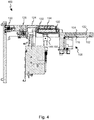
- den Schnitt entlang der Linie IV - IV aus
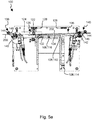
Figur 2 , - Figur 5a
- eine Seitenansicht entlang der Linie V - V aus
Figur 2 mit sich am ersten Anschlag befindender Anpressrolle vor einem Aufstreifen des Hologrammfilms auf den Master, - Figur 5b
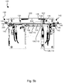
- eine Seitenansicht entlang der Linie V - V aus
Figur 2 mit sich am zweiten Anschlag befindender Anpressrolle und den Filmhubeinrichtungen in der Belichtungskonfiguration, und - Figur 5c
- eine Seitenansicht entlang der Linie V - V aus
Figur 2 mit sich am zweiten Anschlag befindender Anpressrolle vor einem erneuten Aufstreifen des Hologrammfilms auf den Master. - In
Figur 1 ist schematisch eine Hologrammbelichtungsmaschine 300 zum Belichten von Hologrammen in einem Hologrammfilm 200 gezeigt. Eine solche Hologrammbelichtungsmaschine 300 wird auch als Holobelichter bezeichnet. - Die Hologrammbelichtungsmaschine 300 umfasst eine in der Zeichnung oben dargestellte Belichtungseinrichtung 302 und einen in der Zeichnung unten dargestellten Belichtungstisch 100.
- Die Belichtung von Hologrammen erfolgt mittels kohärenten Lichts. Hierfür weist die Belichtungeinrichtung 302 eine Lichtquelle 304 auf, welche vorliegend als ein cw-Laser ausgebildet ist. Vorliegend steht "cw" für "continuous wave" und bedeutet "zeitlich konstant abgestrahlte Welle". Es ist die Möglichkeit gegeben, dass es sich bei der Lichtquelle 304 um einen gepulsten Laser handelt. Das Licht 400 der als Laser ausgebildeten Lichtquelle 304 weist einen ersten Polarisationszustand auf. Zum Führen des Lichts 400 wird eine Strahlführungsoptik 306 verwendet. Das Licht der Lichtquelle 304 wird bei der dargestellten Belichtungseinrichtung 302 zunächst, ggfs. unter Zuhilfenahme einer Strahlformungseinrichtung 322 zur insbesondere in einer Raumrichtung orientierten Strahlaufweitung, auf eine Ablenk- und Scanvorrichtung 310 der Strahlführungsoptik 306 geführt. Diese Ablenk- und Scanvorrichtung 310 umfasst einen Galvanometerscanner und einen mit dem Galvanometerscanner gekoppelten Spiegel 308, an dem das einfallende Licht 400 umgelenkt wird. In einer ersten Stellung ist der Spiegel 308 mittels einer durchgezogenen Linie dargestellt, wobei er in einer zweiten Stellung strichliert gezeigt ist. Durch das Verschieben des Spiegels 308 kann eine einem "Scan", insbesondere einem Linienscan entsprechende Belichtung des Hologramms erfolgen. In anderen Worten wird der Hologrammfilm 200 zur Belichtung des Hologramms "abgetastet". Anders geartete Ablenk- und Scanvorrichtungen 310 für das Licht 400 sind ebenfalls einsetzbar.
- Das abgelenkte Licht 400 wird auf einen polarisationsabhängigen Strahlteilerwürfel 312 der Strahlführungsoptik 306 geführt. Dieser ist aus einem ersten Prisma und einem zweiten Prisma gebildet, an deren Grenzfläche eine polarisationsabhängige Strahlteilung erfolgt. Anstelle von Prismen kann auch eine Strahlteilerplatte Einsatz finden. Licht 400 des ersten Polarisationszustands wird an dieser Grenzfläche abgelenkt. Licht eines weiteren, zu dem ersten Polarisationszustand orthogonalen Polarisationszustands kann hingegen durch die Grenzfläche hindurchtreten.
- Das an der Grenzfläche des polarisationsabhängigen Strahlteilerwürfels 312 abgelenkte Licht 400 wird auf einen räumlichen Lichtmodulator 314 gelenkt, der als sogenannter Liquid-Crystal-on-Silicon-Lichtmodulator (LCoS) ausgebildet ist. Der Lichtmodulator 314 umfasst eine Siliziumschicht 316, an der auftreffendes Licht 400 reflektiert wird. Auf dieser Siliziumschicht 316 sind vorliegend elektronische Schaltelemente ausgebildet, die zum Schalten von Flüssigkristallzellen 318 verwendet werden, die vor der zur Reflexion genutzten Oberfläche der Siliziumschicht 316 angeordnet sind. Die einzelnen Flüssigkristallzellen 318 können individuell in unterschiedliche Schaltzustände versetzt werden. Typischerweise liegt ein Array an Flüssigkristallzellen 318 vor, so dass aus der Papierebene heraus oder in diese hinein versetzt weitere Reihen an Flüssigkristallzellen 318 vorliegen. Abhängig von dem jeweiligen Schaltzustand der Flüssigkristallzellen 318 wird ein Polarisationszustand des durchtretenden Lichts 400 geändert oder nicht geändert, wodurch das Licht 400 räumlich moduliert wird. Vereinfachend wird hier angenommen, dass in einem ersten Schaltzustand das in einem ersten Polarisationszustand auf den Lichtmodulator 314 auftreffende Licht 400 beim Durchtritt durch eine Flüssigkristallzelle 318, welche aufgrund der Reflexion an der Oberfläche der Siliziumschicht 316 zweimal durchlaufen wird, insgesamt hinsichtlich der Polarisation so verändert wird, dass das Licht 400 anschließend in dem zu dem ersten Polarisationszustand orthogonalen weiteren Polarisationszustand polarisiert ist. Dieses hinsichtlich der Polarisation modulierte Licht 400 tritt durch eine transparente Schutzscheibe 320 des räumlichen Lichtmodulators 314, wobei insbesondere eine Austrittsfläche der Schutzscheibe 320 parallel zu der Reflexionsoberfläche der Siliziumschicht 316 orientiert ist. Die Oberflächennormale des Lichtmodulators 314 ist somit orthogonal sowohl zu der Austrittsfläche der Schutzscheibe 320 als auch zu der reflektierenden Oberfläche der Siliziumschicht 316.
- Das modulierte Licht trifft nach dem Austreten aus dem Lichtmodulator 314 erneut auf dem polarisationsabhängigen Strahlteiler 312 auf, wobei das vom LCoS zurückreflektierte modulierte Licht 400 abhängig von seinem Polarisationszustand die Grenzfläche des Strahlteilers 312 passieren kann oder nicht. Ist das modulierte Licht 400, wie im exemplarisch dargestellten Fall, aufgrund des ersten Schaltzustands der Flüssigkristallzelle in den zu dem ersten Polarisationszustand orthogonalen weiteren Polarisationszustand überführt worden, so kann dieses die Grenzfläche des polarisationsabhängigen Strahlteilerwürfels 312 passieren, womit es, ggfs. unter Zuhilfenahme eines Polarisationsfilters 324, weiter in Richtung des Belichtungstisches 100 geleitet wird. Anteile des Lichts 400, die sich nach wie vor in dem ersten Polarisationszustand befinden und an dem polarisationsabhängigen Strahlteilerwürfel 312 ankommen, werden an dessen Grenzfläche abgelenkt und gelangen daher nicht weiter in Richtung des sich unter der Belichtungseinrichtung 302 befindlichen Belichtungstisches 100. Durch den polarisationsabhängigen Strahlteilerwürfel 312 wird somit das Licht 400 abhängig von dem aufmodulierten Polarisationszustand räumlich hinsichtlich der Intensität moduliert.
- Bei der Beschreibung der Belichtungseinrichtung 302 wurde bis hierher davon ausgegangen, dass der räumliche Lichtmodulator 314 den Polarisationszustand des Lichts um 90 Grad dreht oder unverändert lässt. Es sind jedoch auch Änderungen möglich, die eine Drehung der Polarisationsrichtung zwischen 0 Grad und 90 Grad bewirken. Alle diese Drehungen führen dazu, dass das Licht eine veränderte Amplitude und damit veränderte Intensität des weiteren Polarisationszustands aufweist. Je nach Drehwinkel variieren diese und nehmen mit dem Betrag der Drehung zwischen 0 Grad und 90 Grad zu. Hierdurch ist es möglich "Graustufen" zu belichten.
- Der Belichtungstisch 100 weist eine Halteeinrichtung 102 auf, in welcher ein Master 104 aufgenommen ist. Der Master 104 umfasst einen Träger, welcher in der Regel aus Glas oder einem anderen Werkstoff gebildet ist. Auch andere Trägermaterialien sind möglich, beispielsweise Metalle. Auf den Träger ist vorzugsweise mindestens eine optisch aktive Schicht, beispielsweise eine Beugungsschicht, aufgebracht, welche eine zu kopierende Beugungsstruktur umfasst. Vorliegend umfasst die Beugungsschicht des Masters 104 ein Volumenreflexionshologramm, welches kopiert werden soll.
- Es ist zu erkennen, dass die Belichtungsmaschine 300, insbesondere der Belichtungstisch 100 eine Filmtransporteinrichtung 106 umfasst, die ausgebildet ist, den Hologrammfilm 200 relativ bezüglich der Halteeinrichtung 102 und damit relativ zum Master 104 zu transportieren. Die Filmtransporteinrichtung 106 ist für ein Aufnehmen des holografischen Films und Halten und/oder Führen des Films während der Belichtung des Hologramms vorgesehen. Bei der dargestellten Belichtungsmaschine 300 umfasst die Filmtransporteinrichtung 106 eine Filmrolle 110, auf der der Hologrammfilm 200 bereitgestellt wird. Dieser wird nach dem Belichten auf einer weiteren Filmrolle 118 aufgewickelt. Gegebenenfalls durchläuft der belichtete Hologrammfilm 200 eine Strecke zur Entwicklung des Hologramms, durch welche thermisch auf den Hologrammfilm 200 eingewirkt wird, um das Hologramm im Film zu entwickeln, bevor der belichtete Hologrammfilm 200 auf der weiteren Filmrolle 118 wieder aufgewickelt wird. Der Hologrammfilm 200 wird jedenfalls in typischer Weise mittels Filmführungsrollen geführt. Es ist zu erkennen, dass sich der Hologrammfilm 200 über den Bereich des Masters 104 hinweg erstreckt, womit die Filmtransporteinrichtung 106 in anderen Worten also ausgebildet ist, einen zu belichtenden Filmabschnitt 202 relativ bezüglich des Masters 104 zu positionieren. In diesen Filmabschnitt 202 wird das Volumenreflexionshologramm belichtet, mithin einkopiert. Um eine betriebssichere Belichtung des Hologramms zu erzielen, liegt der Hologrammfilm 200 während des Belichtungsvorgangs an dem Master 104 an. Durch diese Anlage lassen sich Eigenbewegungen des holografischen Films unterdrücken, was die erzielbare Beugungseffizienz des hergestellten Hologramms steigert.
- Bei der Belichtung tritt das modulierte Licht 400, welches den weiteren Polarisationszustand aufweist, durch den zu belichtenden Filmabschnitt 202 des Hologrammfilms 200 hindurch und wird an der optisch aktiven Struktur der mindestens einen optisch aktiven Schicht des Masters 104 zurückgelenkt, z.B. bei einer als Beugungsschicht ausgebildeten optisch aktiven Schicht gebeugt. Das zurückgestrahlte Licht (nicht dargestellt) interferiert dann in dem Hologrammfilm 200 mit dem von dem Lichtmodulator 314 kommenden modulierten Licht 400. Hierdurch wird die optisch aktive Struktur, z.B. die beugende Struktur, des Masters 104 in den Hologrammfilm 200 einbelichtet. Hierbei wird die optisch aktive Struktur pixelweise abhängig von der räumlichen Modulation entweder belichtet und kopiert oder andererseits nicht belichtet und somit auch nicht kopiert. Es entsteht somit eine Kopie der optisch aktiven Struktur, beispielsweise eine Kopie eines Volumenreflexionshologramms einer Mattscheibe.
- Die vorliegende Erfindung betrifft die Gestaltung und die Betriebsweise des Belichtungstisches 100, der in
Figur 2 in einer Draufsicht näher zu erkennen ist. Die hierbei gezeigte Halteeinrichtung 102 ist nach Art eines Drehtellers gestaltet und weist zwei Aufnahmen für einen Master 104 auf. Eine andere Anzahl an Masteraufnahmen ist möglich, sodass auch drei oder mehr Master 104 auf ein- und derselben Halteeinrichtung 102 angeordnet werden können. Um die sehr empfindlichen Kanten des Masters 104 zu schützen, ist die Aufnahme der Halteeinrichtung 102 derart ausgestaltet, dass der Master 104 gegenüber der Halteeinrichtung 102 versenkt angeordnet ist vorzugsweise aber mit letzterer in einer gemeinsamen Ebene liegt. - Die Filmtransporteinrichtung 106 umfasst eine filmaufwärts des Masters 104 gelegene erste Filmhubeinrichtung 138 und eine filmabwärts des Masters 104 gelegene zweite Filmhubeinrichtung 140, die jeweils eine Filmhubwalze 142 und eine Führungswalze 144 bestehen. Die Filmhubwalze 142 ist achsparallel zur Führungswalze 144 angeordnet, wobei die Führungswalze 144 selbst an einem begrenzt um die Achse der Filmhubwalze 142 verschwenkbaren Hebelarm 146 drehbar gelagert ist. Hierzu weist die betreffende Filmhubeinrichtung 138, 140 entsprechende bogenförmige Langlöcher auf (
Fig. 5a bis 5c ). Die Verstellung des Hebelarms 146 kann dabei druckmittelbetätigt, insbesondere pneumatisch erfolgen. Auch das Heben und Senken der Filmhubeinrichtungen 138, 140 erfolgt druckmittelbetätigt, insbesondere pneumatisch. Die Filmhubeinrichtungen 138, 140 der Filmtransporteinrichtung 106 gewährleisten während des Transports einen minimalen Abstand zwischen der Halteeinrichtung 102 und dem Hologrammfilm 200, sodass dieser keine Beschädigungen erfährt. Dieser Abstand kann beispielsweise zwischen 0,4 Millimeter und 1,1 Millimeter betragen, wodurch der Belichtungstisch 100 und damit die mit diesem gebildete Belichtungsmaschine 300 sehr platzsparend und kompakt gestaltet sind. - Ausweislich
Figur 3 ist der Halteeinrichtung 102 vorliegend eine Drucklufteinrichtung 108 zugeordnet, die ausgebildet ist, für die Belichtung des Filmabschnitts 202 diesen mittels eines Unterdrucks an dem in der Halteeinrichtung 102 aufgenommenen Master 104 zumindest zeitweise zu fixieren. Hierzu ist vorliegend ein um den Master 104 umfangsseitig angeordneter Schlitz vorhanden, der somit eine Gasdurchtrittsanordnung 112 bildet. Die Gasdurchtrittsanordnung 112 rahmt also den Master 104 umfangsseitig und gewährleistet damit ein blasenfreies Anliegen des zu belichtenden Filmabschnitts 202 am Master 104. Vorliegend kann die Drucklufteinrichtung 108 aber zusätzlich dazu genutzt werden, um zeitweise einen Überdruck derart bereitzustellen, dass der Transport des Hologrammfilms 200 relativ bezüglich des Masters 104 von einem Luftpolster gestützt erfolgt, was Beschädigungen des Hologrammfilms 200 zusätzlich vorbeugt. In den Figuren ist zu erkennen, dass zur Erzeugung des erforderlichen Unterdrucks oder Vakuums die Drucklufteinrichtung 108 vorliegend eine pneumatische Venturisaugdüse 114 umfasst, die mit der Gasdurchtrittsanordnung 112 über einen oder mehrere Kanäle 116 strömungsmechanisch verbunden und in geeigneter Weise mit Ventilen verschaltet ist. - Um Gaseinschlüsse zwischen dem Hologrammfilm 200 und dem Master 104 zusätzlich herausdrücken zu können, ist vorliegend außerdem eine Aufstreifeinrichtung 120 vorhanden um den zu belichtenden Filmabschnitt 202 auf den Master 104 aufzustreifen. Diese Aufstreifeinrichtung 120 ist vorliegend durch einen zwischen zwei Anschlägen 136 verschiebbaren Schlitten 124 gebildet, an dem eine auf einer Drehachse drehbar gelagerte und beim Aufstreifen mit dem Filmabschnitt 202 wechselwirkende Anpressrolle 122 gelagert ist. Der Schlitten 124 selbst ist vorliegend um eine senkrecht bezüglich der Drehachse der Anpressrolle 122 orientierte Verfahrachse 126 begrenzt verschwenkbar gelagert, wodurch sich die Anpressrolle 122 selbst zwischen einer angehobenen Stellung und einer abgesenkten Stellung verstellen lässt. An den Anschlägen 136 oder anschlagsnah ist jeweils eine Steuerkurve 128 vorhanden, die ausgebildet ist, die Anpressrolle 122 zwischen der angehobenen Stellung und der abgesenkten Stellung zu verstellen, wenn der Schlitten 124 mit den Steuerkurven 128 wechselwirkt.
- Ausweislich
Figur 4 ist zu erkennen, dass dem Schlitten 124 auf seiner dem Master 104 abgewandten Seite eine Federanordnung 130 zugeordnet ist, die den Anpressdruck der Anpressrolle 122 auf den Master 104 oder auf den sich am Master 104 befindenden Filmabschnitt 202 einstellt oder vorgibt. Diese Federanordnung 130 übt eine Federkraft auf den um die Verfahrachse 126 verschwenkbaren Schlitten 124 aus, sodass die Anpresskraft der Anpressrolle 122 im Bereich zwischen den beiden Anschlägen 136 maximal ist. Durch die Anschläge 136 und/oder die Steuerkurven 128 wird die Federanordnung 130 aber zumindest teilweise, vorzugsweise gänzlich, außer Kraft gesetzt, womit die Anpressrolle 122 vom Hologrammfilm 200 abgehoben werden kann, wenn sich der Schlitten 124 in seinen Endlagen befindet. Der Schlitten 124 wird vorliegend zwischen den beiden Anschlägen 136 ebenfalls druckmittelbetätigt, insbesondere pneumatisch verstellt. Eine hydraulische oder motorische Verstellung ist ebenfalls möglich. - Es ist zusätzlich zu erkennen, dass dem Schlitten 124 ein Haltearm 132 zugeordnet ist, an welchem die Anpressrolle 122 drehbar gelagert ist. Dieser Haltearm 132 weist eine senkrecht zur Drehachse der Anpressrolle 122 orientierte Schwenkachse 134 auf, sodass der Haltearm 132 derart an dem Schlitten 124 fixiert ist, dass der Haltearm 132 und damit die Anpressrolle 122 begrenzt verschwenkbar gegenüber dem Schlitten 124 gelagert sind, um dadurch eine Ausgleichsbewegung ausführen zu können, die durch Toleranzschwankungen oder durch etwaige Unebenheiten erzeugt werden.
- Um den Hologrammfilm 200 vor dem Belichten möglichst staubfrei zu halten und diesen damit vor Kratzern zu schützen, ist vorliegend eine Reinigungseinrichtung 148 vorhanden. Die Reinigungseinrichtung 148 umfasst vorliegend eine in der Filmtransportrichtung orientierte und filmaufwärts des Masters 104 angeordnete erste Sprühdüse 150 für ionisierte Luft sowie eine entgegen der Filmtransportrichtung orientierte filmabwärts des Masters 104 angeordnete zweite Sprühdüse 152 für ionisierte Luft. Mit dieser ionisierten Luft kann zusätzlich zur Reinigungsfunktion das Luftpolster während des Transports zwischen dem Hologrammfilm 200 und der Halteeinrichtung 102 aufrechterhalten oder unterstützt werden, sodass der Reinigungseinrichtung 148 eine Doppelfunktion zukommt.
- Anhand der
Figuren 5a bis 5c wird nachstehend erläutert, wie eine Mehrzahl von Filmabschnitten 202 am Master 104 des Belichtungstisches 100 fixiert und belichtet wird. - Zunächst wird der zu belichtende Filmabschnitt 202 zu dem in der Halteeinrichtung 102 aufgenommenen Master 104 mittels der Filmtransporteinrichtung 106 transportiert, wobei sich die filmabwärts des Masters 104 gelegene zweite Filmhubeinrichtung 140 in einer angehobenen, der Transportkonfiguration entsprechenden Stellung befindet. Zeitgleich oder anschließend wird die erste Filmhubeinrichtung 138 der Filmtransporteinrichtung 106 in eine abgesenkte, einer Belichtungskonfiguration entsprechenden Stellung verstellt, sodass der Hologrammfilm 200 gegenüber dem Master 104 derart gehalten wird, dass die Oberfläche des zu belichtenden Filmabschnitts 202 und die Oberfläche des Masters 104 unter einem spitzen Winkel aufeinander zu oder voneinander weg verlaufend orientiert sind. Nun wird mittels der Anpressrolle 122 der Aufstreifeinrichtung 120 der Filmabschnitt 202 auf den Master 104 ausgehend von dem spitzen Winkel auf den Master 104 aufgestreift, wobei zusätzlich eine Saugluft, also ein Unterdruck an oder um den Master 104 mittels der Drucklufteinrichtung 108 vorliegt.
- In
Figur 5a wird dabei also die Anpressrolle 122 aus ihrer linken Stellung in die inFigur 5b gezeigte rechte Stellung verfahren. Zeitgleich oder anschließend wird auch die zweite Filmhubeinrichtung 140 in die abgesenkte Stellung überführt, sodass dann eine Belichtung des Filmabschnitts 202 erfolgen kann. In vorteilhafter Weise und zur Vermeidung von unerwünschten Effekten beispielsweise durch Newton-Ringe, wird dann die Saugluft reduziert oder der Unterdruck auf ein niedrigeres Maß eingestellt, wobei in einer vorteilhaften Ausgestaltung der Filmabschnitt 202 drucklos am Master 104 gelagert ist. Anschließend wird der Filmabschnitt 202 durch Beleuchten mit dem modulierten Licht 400 belichtet, wodurch das Volumenreflexionshologramm in den Filmabschnitt 202 kopiert wird. - Anschließend wird der Hologrammfilm 200 mittels der Filmtransporteinrichtung 106 weitertransportiert und ein neuer Filmabschnitt gegenüber dem Master 104 positioniert. Dabei wird dann ausweislich
Figur 5c nun die erste Filmhubeinrichtung 138 in ihre angehobene Stellung überführt, wobei die zweite Filmhubeinrichtung 140 in der abgesenkten Stellung verbleibt. Nun ist der spitze Winkel, der durch die Oberfläche des zu belichtenden Filmabschnitt 202 und die Oberfläche des Masters 104 gebildet ist, filmab des Masters 104 angeordnet, sodass jetzt die Anpressrolle 122 den neuen Filmabschnitt 202 in der Zeichnung von rechts nach links auf den Master 104 aufstreifen kann, wobei dabei in vorteilhafter Weise zusätzlich wieder ein Unterdruck durch die Drucklufteinrichtung 108 an oder um den Master 104 bereitgestellt ist. Somit hat es sich also als sinnvoll und vorteilhaft erwiesen, dass zum Belichten mehrerer Filmabschnitte 202 des Hologrammfilms 200 der spitze Winkel alternierend auf der filmabwärts gelegenen Seite des Masters 104 und auf der filmaufwärts gelegenen Seite des Masters 104 angeordnet wird, und dass die Aufstreifeinrichtung 120 mit ihrer Anpressrolle 122 den zu belichtenden Filmabschnitt 202 dazu korrespondierend, ebenfalls alternierend ausgehend von der filmabwärtsgelegenen Seite des Masters 104 und ausgehend von der filmaufwärts gelegenen Seite des Masters 104 aufstreift. Dies reduziert außerdem die Taktzeit bei einer Herstellung einer Mehrzahl von zu belichtenden Filmabschnitten 202. - Für die Steuerung der einzelnen Konstituenten der Belichtungsmaschine 300 ist außerdem eine Steuerungseinrichtung 326 vorhanden (
Fig. 1 ). Die Steuerungseinrichtung 326 ist dabei in vorteilhafter Weise ausgebildet, die Lichtquelle 304 und/oder die Ablenk- und Scaneinrichtung 310 und/oder den Lichtmodulator 314 und/oder die Filmtransporteinrichtung 106 und/oder die Drucklufteinrichtung 108 und/oder die Aufstreifeinrichtung 120 und/oder die Reinigungseinrichtung 148 zu steuern. -
- 100
- Belichtungstisch
- 102
- Halteeinrichtung
- 104
- Master
- 106
- Filmtransporteinrichtung
- 108
- Drucklufteinrichtung (Saugeinrichtung und/oder Blaseinrichtung)
- 110
- Filmrolle (unbelichteter Holofilm)
- 112
- Gasdurchtrittsanordnung
- 114
- Venturisaugdüse
- 116
- Kanal (Druckluft/Saugluft)
- 118
- weitere Filmrolle (belichteter Holofilm)
- 120
- Aufstreifeinrichtung
- 122
- Anpressrolle
- 124
- Schlitten
- 126
- Verfahrachse (Schlitten)
- 128
- Steuerkurve
- 130
- Federanordnung
- 132
- Haltearm
- 134
- Schwenkachse
- 136
- Anschlag
- 138
- erste Filmhubeinrichtung
- 140
- zweite Filmhubeinrichtung
- 142
- Filmhubwalze
- 144
- Führungswalze
- 146
- Hebelarm
- 148
- Reinigungseinrichtung
- 150
- erste Sprühdüse
- 152
- zweite Sprühdüse
- 200
- Hologrammfilm
- 202
- Filmabschnitt (zu belichtender Filmabschnitt)
- 300
- Hologrammbelichtungsmaschine
- 302
- Belichtungseinrichtung
- 304
- Lichtquelle (z.B. Laser)
- 306
- Strahlführungsoptik
- 308
- Spiegel
- 310
- Ablenk- und Scaneinrichtung
- 312
- Strahlteiler
- 314
- Lichtmodulator
- 316
- Siliziumschicht
- 318
- Flüssigkristallzelle
- 320
- Schutzscheibe
- 322
- Strahlformungseinrichtung (z.B. Powell- oder Zylinderlinse)
- 324
- Polarisationsfilter
- 326
- Steuerungseinrichtung
Claims (15)
- Belichtungstisch (100) für eine Hologrammbelichtungsmaschine (300),
mit einer Halteeinrichtung (102), in welcher ein Master (104) aufgenommen ist, und mit einer Filmtransporteinrichtung (106), die ausgebildet ist, einen Hologrammfilm (200) relativ bezüglich der Halteeinrichtung (102) zu transportieren und einen zu belichtenden Filmabschnitt (202) relativ bezüglich des Masters (104) für eine Hologrammbelichtung zu positionieren,
dadurch gekennzeichnet, dass
der Halteeinrichtung (102) eine Drucklufteinrichtung (108) zugeordnet ist, die ausgebildet ist, den Filmabschnitt (202) mittels eines Unterdrucks an dem in der Halteeinrichtung (102) aufgenommenen Master (104) zumindest zeitweise zu fixieren. - Belichtungstisch (100) nach Anspruch 1, dadurch gekennzeichnet, dass die Drucklufteinrichtung (108) ausgebildet ist, zumindest zeitweise einen Überdruck derart bereitzustellen, dass der Transport des Hologrammfilms (200) relativ bezüglich des Masters (104) von einem Luftpolster gestützt erfolgt.
- Belichtungstisch (100) nach Anspruch 1 oder 2, dadurch gekennzeichnet, dass die Drucklufteinrichtung (108) mindestens eine Gasdurchtrittsanordnung (112) umfasst, die randseitig bezüglich des in der Halteeinrichtung (102) aufgenommenen Masters (104) angeordnet ist und/oder die in dem Master (104) selbst ausgebildet ist, dass die Gasdurchtrittsanordnung (112) den Master (104) umfangsseitig rahmt, und dass die Gasdurchtrittsanordnung (112) durch einen Schlitz oder durch eine mehrere Bohrungen umfassende Bohrungsanordnung gebildet ist.
- Belichtungstisch (100) nach einem der Ansprüche 1 bis 3, dadurch gekennzeichnet, dass eine Aufstreifeinrichtung (120) vorhanden ist, um den zu belichtenden Filmabschnitt (202) auf den Master (104) aufzustreifen, und dass die Aufstreifeinrichtung (120) einen zwischen zwei Anschlägen (136) verschiebbaren Schlitten (124) umfasst, an welchem eine auf einer Drehachse drehbar gelagerte und mit dem Filmabschnitt (202) wechselwirkende Anpressrolle (122) gelagert ist.
- Belichtungstisch (100) nach Anspruch 4, dadurch gekennzeichnet,
dass der Schlitten (124) um eine senkrecht bezüglich der Drehachse der Anpressrolle (122) orientierte Verfahrachse (126) begrenzt verschwenkbar gelagert und damit die Anpressrolle (122) zwischen einer angehobenen Stellung und einer abgesenkten Stellung verstellbar ist,
und dass jeweils eine Steuerkurve (128) vorhanden ist, die ausgebildet ist, die Anpressrolle (122) zwischen der angehobenen Stellung und der abgesenkten Stellung zu verstellen. - Belichtungstisch (100) nach Anspruch 4 oder 5, dadurch gekennzeichnet, dass dem Schlitten (124) auf seiner dem Master (104) abgewandten Seite eine Federanordnung (130) zugeordnet ist, die den Anpressdruck der Anpressrolle (122) auf den Master (104) oder auf den sich am Master (104) befindenden Filmabschnitt (202) einstellt oder vorgibt.
- Belichtungstisch (100) nach einem der Ansprüche 4 bis 6, dadurch gekennzeichnet, dass die Anpressrolle (122) an einem Haltearm (132) drehbar gelagert ist, der mittels einer, senkrecht zur Drehachse orientierte Schwenkachse (134) derart an dem Schlitten (124) fixiert ist, dass der Haltearm (132) und damit die Anpressrolle (122) begrenzt verschwenkbar gegenüber dem Schlitten (124) gelagert sind.
- Belichtungstisch (100) nach einem der Ansprüche 1 bis 7, dadurch gekennzeichnet, dass die Filmtransporteinrichtung (106) eine erste Filmhubeinrichtung (138) umfasst, die zwischen einer angehobenen, einer Transportkonfiguration entsprechenden Stellung und einer abgesenkten, einer Belichtungskonfiguration entsprechenden Stellung verstellbar ist.
- Belichtungstisch (100) nach Anspruch 8, dadurch gekennzeichnet, dass die Filmtransporteinrichtung (106) eine zweite Filmhubeinrichtung (140) umfasst, die zwischen einer angehobenen, einer Transportkonfiguration entsprechenden Stellung und einer abgesenkten, einer Belichtungskonfiguration entsprechenden Stellung verstellbar ist.
- Belichtungstisch (100) nach Anspruch 8 oder 9, dadurch gekennzeichnet, dass die erste Filmhubeinrichtung (138) und/oder die zweite Filmhubeinrichtung (140) eine um eine Achse drehbare Filmhubwalze (142) umfasst.
- Belichtungstisch (100) nach Anspruch 10, dadurch gekennzeichnet, dass die erste Filmhubeinrichtung (138) und/oder die zweite Filmhubeinrichtung (140) eine zur Filmhubwalze (142) achsparallel angeordnete Führungswalze (144) umfasst, die an einem begrenzt um die Achse verschwenkbaren Hebelarm (146) drehbar gelagert ist.
- Verfahren zum Einbringen eines Volumenhologramms in einen Filmabschnitt (202) eines Hologrammfilms (200), umfassend die Schritte:- Transportieren des zu belichtenden Filmabschnitts (202) zu einem in einer Halteeinrichtung (102) aufgenommenen Master (104) mittels einer Filmtransporteinrichtung (106),- Fixieren des zu belichtenden Filmabschnitts (202) durch Anlegen eines Unterdrucks an oder um den Master (104) mittels einer Drucklufteinrichtung (108), und- Belichten zumindest eines Teils des Filmabschnitts mittels einer Belichtungseinrichtung (302).
- Verfahren nach Anspruch 12, dadurch gekennzeichnet, dass die Drucklufteinrichtung (108) während des Transports des Hologrammfilms (200) einen Überdruck derart bereitstellt, dass der Hologrammfilm (200) auf einem Luftpolster gleitet.
- Verfahren nach Anspruch 12 oder 13, dadurch gekennzeichnet, dass der Hologrammfilm (200) zum Fixieren des Filmabschnitts (202) derart gegenüber dem Master (104) gehalten wird, dass die Oberfläche des zu belichtenden Filmabschnitts (202) und die Oberfläche des Masters (104) unter einem spitzen Winkel aufeinander zu oder voneinander weg verlaufend orientiert sind, und dass der Filmabschnitt (202) auf den Master (104) ausgehend von dem spitzen Winkel mittels einer Aufstreifeinrichtung (120) aufgestreift wird.
- Verfahren nach Anspruch 14, dadurch gekennzeichnet, dass zum Belichten mehrerer Filmabschnitte (202) des Hologrammfilms (200) der spitze Winkel alternierend auf der filmabwärts gelegenen Seite des Masters (104) und auf der filmaufwärts gelegen Seite des Masters (104) angeordnet wird, und dass die Aufstreifeinrichtung (120) den zu belichtenden Filmabschnitt (202) dazu korrespondierend, ebenfalls alternierend ausgehend von der filmabwärts gelegenen Seite des Masters (104) und ausgehend von der filmaufwärts gelegenen Seite des Masters (104) aufstreift.
Applications Claiming Priority (1)
| Application Number | Priority Date | Filing Date | Title |
|---|---|---|---|
| DE102020103612.4A DE102020103612B4 (de) | 2020-02-12 | 2020-02-12 | Belichtungstisch für eine hologrammbelichtungsmaschine und verfahren zum einbringen eines volumenhologramms in einen filmabschnitt |
Publications (2)
| Publication Number | Publication Date |
|---|---|
| EP3865951A1 true EP3865951A1 (de) | 2021-08-18 |
| EP3865951B1 EP3865951B1 (de) | 2025-07-09 |
Family
ID=74572655
Family Applications (1)
| Application Number | Title | Priority Date | Filing Date |
|---|---|---|---|
| EP21155909.1A Active EP3865951B1 (de) | 2020-02-12 | 2021-02-09 | Belichtungstisch für eine hologrammbelichtungsmaschine und verfahren zum einbringen eines volumenhologramms in einen filmabschnitt |
Country Status (2)
| Country | Link |
|---|---|
| EP (1) | EP3865951B1 (de) |
| DE (1) | DE102020103612B4 (de) |
Citations (8)
| Publication number | Priority date | Publication date | Assignee | Title |
|---|---|---|---|---|
| EP0896260A2 (de) | 1997-08-06 | 1999-02-10 | HSM Holographic Systems München GmbH | Vorrichtung für die Herstellung von individuellen Hologrammen zum Sichern von Dokumenten |
| JPH11249535A (ja) * | 1998-03-02 | 1999-09-17 | Dainippon Printing Co Ltd | ホログラム複製用原版の保持装置 |
| DE102007042386A1 (de) | 2007-09-04 | 2009-03-05 | Bundesdruckerei Gmbh | Verfahren und Vorrichtung zur individuellen farbigen holografischen Belichtung |
| DE102007042385A1 (de) | 2007-09-04 | 2009-03-05 | Bundesdruckerei Gmbh | Verfahren und Vorrichtung zur individuellen holografischen Trommelbelichtung |
| JP4318996B2 (ja) * | 2003-09-25 | 2009-08-26 | 大日本印刷株式会社 | 光回折構造の製造方法 |
| DE102012215540A1 (de) | 2012-08-31 | 2014-03-06 | Bundesdruckerei Gmbh | Individualisierungseinrichtung und Belichtungsvorrichtung für Hologramme |
| DE102013200980A1 (de) * | 2013-01-22 | 2014-07-24 | Bundesdruckerei Gmbh | Verfahren zur nachträglichen holografischen Beschriftung sowie Halbzeug und Vorrichtung zur nachträglichen holografischen Beschriftung |
| KR102001019B1 (ko) * | 2018-10-12 | 2019-07-17 | (주)한교홀로그램 | 홀로그램 전사 장치 |
Family Cites Families (1)
| Publication number | Priority date | Publication date | Assignee | Title |
|---|---|---|---|---|
| DE102010014305A1 (de) | 2010-04-09 | 2011-10-13 | Hologram Industries Research Gmbh | Verfahren und Vorrichtung zum Herstellen Kontaktkopien von Reflexions-Volumenhologrammen |
-
2020
- 2020-02-12 DE DE102020103612.4A patent/DE102020103612B4/de active Active
-
2021
- 2021-02-09 EP EP21155909.1A patent/EP3865951B1/de active Active
Patent Citations (8)
| Publication number | Priority date | Publication date | Assignee | Title |
|---|---|---|---|---|
| EP0896260A2 (de) | 1997-08-06 | 1999-02-10 | HSM Holographic Systems München GmbH | Vorrichtung für die Herstellung von individuellen Hologrammen zum Sichern von Dokumenten |
| JPH11249535A (ja) * | 1998-03-02 | 1999-09-17 | Dainippon Printing Co Ltd | ホログラム複製用原版の保持装置 |
| JP4318996B2 (ja) * | 2003-09-25 | 2009-08-26 | 大日本印刷株式会社 | 光回折構造の製造方法 |
| DE102007042386A1 (de) | 2007-09-04 | 2009-03-05 | Bundesdruckerei Gmbh | Verfahren und Vorrichtung zur individuellen farbigen holografischen Belichtung |
| DE102007042385A1 (de) | 2007-09-04 | 2009-03-05 | Bundesdruckerei Gmbh | Verfahren und Vorrichtung zur individuellen holografischen Trommelbelichtung |
| DE102012215540A1 (de) | 2012-08-31 | 2014-03-06 | Bundesdruckerei Gmbh | Individualisierungseinrichtung und Belichtungsvorrichtung für Hologramme |
| DE102013200980A1 (de) * | 2013-01-22 | 2014-07-24 | Bundesdruckerei Gmbh | Verfahren zur nachträglichen holografischen Beschriftung sowie Halbzeug und Vorrichtung zur nachträglichen holografischen Beschriftung |
| KR102001019B1 (ko) * | 2018-10-12 | 2019-07-17 | (주)한교홀로그램 | 홀로그램 전사 장치 |
Non-Patent Citations (1)
| Title |
|---|
| ANONYMOUS: "Apparatus and method for replicating holograms in a recording film", RESEARCH DISCLOSURE, KENNETH MASON PUBLICATIONS, HAMPSHIRE, UK, GB, vol. 404, no. 2, 1 December 1997 (1997-12-01), XP007122187, ISSN: 0374-4353 * |
Also Published As
| Publication number | Publication date |
|---|---|
| DE102020103612A1 (de) | 2021-08-12 |
| EP3865951B1 (de) | 2025-07-09 |
| DE102020103612B4 (de) | 2023-10-19 |
Similar Documents
| Publication | Publication Date | Title |
|---|---|---|
| EP2203790B1 (de) | Verfahren und vorrichtung zur individuellen holografischen trommelbelichtung | |
| DE602004001779T2 (de) | Maschine und verfahren zum schneiden von öffnungen in ein substrat | |
| DE102012215540B4 (de) | Individualisierungseinrichtung und Belichtungsvorrichtung für Hologramme | |
| DE102013200980B4 (de) | Verfahren zur nachträglichen holografischen Beschriftung sowie Vorrichtung zur nachträglichen holografischen Beschriftung | |
| DE60035300T2 (de) | Optische Abtastvorrichtung, Bilderzeugungsgerät und diese Abtastvorrichtung verwendender elektrophotographischer Drucker | |
| DE69619570T2 (de) | Mediaführungsvorrichtung in einem Abtastsystem | |
| WO2010054636A1 (de) | Verfahren und vorrichtung zum herstellen von volumen-transmissions- und/oder reflexionshologrammen | |
| DE102020103613B4 (de) | Belichtungstisch für eine hologrammbelichtungsmaschine und verfahren zum einbringen eines volumenreflexionshologramms in einen filmabschnitt | |
| EP3865951B1 (de) | Belichtungstisch für eine hologrammbelichtungsmaschine und verfahren zum einbringen eines volumenhologramms in einen filmabschnitt | |
| EP3869275B1 (de) | Belichtungstisch für eine hologrammbelichtungsmaschine | |
| DE102020103616B4 (de) | Hologrammbelichtungsmaschine und strahlformungseinrichtung für eine solche | |
| DE102020103617B4 (de) | Hologrammbelichtungsmaschine zum einbringen eines volumenreflexionshologramms in einen filmabschnitt eines hologrammfilms und verfahren zum einbringen mehrerer volumenreflexionshologramme in einen filmabschnitt eines hologrammfilms | |
| DE3021460A1 (de) | Vorlagenbeleuchtungseinrichtung | |
| EP3792699A1 (de) | Vorrichtung und verfahren zur erfassung eines holografischen merkmals | |
| DE102009031871B4 (de) | Verfahren und Vorrichtung zur Laserbeschriftung | |
| DE102020103618B4 (de) | Hologrammbelichtungsmaschine und verfahren zum justieren einer hologrammbelichtungsmaschine | |
| EP3865950A1 (de) | Hologrammbelichtungsmaschine zum einbringen eines volumenreflexionshologramm in einen hologrammfilm | |
| EP3755543B1 (de) | Vorrichtung und verfahren zum einbringen von informationen in einen datenträger | |
| DE19802712B4 (de) | Verfahren und Vorrichtung zur Belichtung von computergenerierten Hologrammen | |
| DE3035953C2 (de) | Fotokopiergerät |
Legal Events
| Date | Code | Title | Description |
|---|---|---|---|
| PUAI | Public reference made under article 153(3) epc to a published international application that has entered the european phase |
Free format text: ORIGINAL CODE: 0009012 |
|
| STAA | Information on the status of an ep patent application or granted ep patent |
Free format text: STATUS: THE APPLICATION HAS BEEN PUBLISHED |
|
| AK | Designated contracting states |
Kind code of ref document: A1 Designated state(s): AL AT BE BG CH CY CZ DE DK EE ES FI FR GB GR HR HU IE IS IT LI LT LU LV MC MK MT NL NO PL PT RO RS SE SI SK SM TR |
|
| STAA | Information on the status of an ep patent application or granted ep patent |
Free format text: STATUS: REQUEST FOR EXAMINATION WAS MADE |
|
| 17P | Request for examination filed |
Effective date: 20220214 |
|
| RBV | Designated contracting states (corrected) |
Designated state(s): AL AT BE BG CH CY CZ DE DK EE ES FI FR GB GR HR HU IE IS IT LI LT LU LV MC MK MT NL NO PL PT RO RS SE SI SK SM TR |
|
| P01 | Opt-out of the competence of the unified patent court (upc) registered |
Effective date: 20230526 |
|
| GRAP | Despatch of communication of intention to grant a patent |
Free format text: ORIGINAL CODE: EPIDOSNIGR1 |
|
| STAA | Information on the status of an ep patent application or granted ep patent |
Free format text: STATUS: GRANT OF PATENT IS INTENDED |
|
| RIC1 | Information provided on ipc code assigned before grant |
Ipc: B65H 20/14 20060101ALI20250210BHEP Ipc: B25B 11/00 20060101ALI20250210BHEP Ipc: B32B 37/00 20060101ALI20250210BHEP Ipc: B32B 37/10 20060101ALI20250210BHEP Ipc: B32B 38/18 20060101ALI20250210BHEP Ipc: B65H 5/22 20060101ALI20250210BHEP Ipc: B65H 9/08 20060101ALI20250210BHEP Ipc: B65H 9/10 20060101ALI20250210BHEP Ipc: B65H 16/02 20060101ALI20250210BHEP Ipc: B65H 23/16 20060101ALI20250210BHEP Ipc: G03H 1/20 20060101ALI20250210BHEP Ipc: G03H 1/02 20060101AFI20250210BHEP |
|
| INTG | Intention to grant announced |
Effective date: 20250314 |
|
| GRAS | Grant fee paid |
Free format text: ORIGINAL CODE: EPIDOSNIGR3 |
|
| GRAA | (expected) grant |
Free format text: ORIGINAL CODE: 0009210 |
|
| STAA | Information on the status of an ep patent application or granted ep patent |
Free format text: STATUS: THE PATENT HAS BEEN GRANTED |
|
| AK | Designated contracting states |
Kind code of ref document: B1 Designated state(s): AL AT BE BG CH CY CZ DE DK EE ES FI FR GB GR HR HU IE IS IT LI LT LU LV MC MK MT NL NO PL PT RO RS SE SI SK SM TR |
|
| REG | Reference to a national code |
Ref country code: GB Ref legal event code: FG4D Free format text: NOT ENGLISH |
|
| REG | Reference to a national code |
Ref country code: CH Ref legal event code: EP |
|
| REG | Reference to a national code |
Ref country code: IE Ref legal event code: FG4D Free format text: LANGUAGE OF EP DOCUMENT: GERMAN |
|
| REG | Reference to a national code |
Ref country code: DE Ref legal event code: R096 Ref document number: 502021007935 Country of ref document: DE |
|
| REG | Reference to a national code |
Ref country code: NL Ref legal event code: MP Effective date: 20250709 |
|
| PG25 | Lapsed in a contracting state [announced via postgrant information from national office to epo] |
Ref country code: PT Free format text: LAPSE BECAUSE OF FAILURE TO SUBMIT A TRANSLATION OF THE DESCRIPTION OR TO PAY THE FEE WITHIN THE PRESCRIBED TIME-LIMIT Effective date: 20251110 |
|
| PG25 | Lapsed in a contracting state [announced via postgrant information from national office to epo] |
Ref country code: NL Free format text: LAPSE BECAUSE OF FAILURE TO SUBMIT A TRANSLATION OF THE DESCRIPTION OR TO PAY THE FEE WITHIN THE PRESCRIBED TIME-LIMIT Effective date: 20250709 |
|
| PG25 | Lapsed in a contracting state [announced via postgrant information from national office to epo] |
Ref country code: IS Free format text: LAPSE BECAUSE OF FAILURE TO SUBMIT A TRANSLATION OF THE DESCRIPTION OR TO PAY THE FEE WITHIN THE PRESCRIBED TIME-LIMIT Effective date: 20251109 |
|
| PG25 | Lapsed in a contracting state [announced via postgrant information from national office to epo] |
Ref country code: NO Free format text: LAPSE BECAUSE OF FAILURE TO SUBMIT A TRANSLATION OF THE DESCRIPTION OR TO PAY THE FEE WITHIN THE PRESCRIBED TIME-LIMIT Effective date: 20251009 |
|
| REG | Reference to a national code |
Ref country code: LT Ref legal event code: MG9D |
|
| PG25 | Lapsed in a contracting state [announced via postgrant information from national office to epo] |
Ref country code: FI Free format text: LAPSE BECAUSE OF FAILURE TO SUBMIT A TRANSLATION OF THE DESCRIPTION OR TO PAY THE FEE WITHIN THE PRESCRIBED TIME-LIMIT Effective date: 20250709 |
|
| PG25 | Lapsed in a contracting state [announced via postgrant information from national office to epo] |
Ref country code: HR Free format text: LAPSE BECAUSE OF FAILURE TO SUBMIT A TRANSLATION OF THE DESCRIPTION OR TO PAY THE FEE WITHIN THE PRESCRIBED TIME-LIMIT Effective date: 20250709 |
|
| PG25 | Lapsed in a contracting state [announced via postgrant information from national office to epo] |
Ref country code: GR Free format text: LAPSE BECAUSE OF FAILURE TO SUBMIT A TRANSLATION OF THE DESCRIPTION OR TO PAY THE FEE WITHIN THE PRESCRIBED TIME-LIMIT Effective date: 20251010 |
|
| PG25 | Lapsed in a contracting state [announced via postgrant information from national office to epo] |
Ref country code: SE Free format text: LAPSE BECAUSE OF FAILURE TO SUBMIT A TRANSLATION OF THE DESCRIPTION OR TO PAY THE FEE WITHIN THE PRESCRIBED TIME-LIMIT Effective date: 20250709 |
|
| PG25 | Lapsed in a contracting state [announced via postgrant information from national office to epo] |
Ref country code: LV Free format text: LAPSE BECAUSE OF FAILURE TO SUBMIT A TRANSLATION OF THE DESCRIPTION OR TO PAY THE FEE WITHIN THE PRESCRIBED TIME-LIMIT Effective date: 20250709 |
|
| PG25 | Lapsed in a contracting state [announced via postgrant information from national office to epo] |
Ref country code: BG Free format text: LAPSE BECAUSE OF FAILURE TO SUBMIT A TRANSLATION OF THE DESCRIPTION OR TO PAY THE FEE WITHIN THE PRESCRIBED TIME-LIMIT Effective date: 20250709 Ref country code: PL Free format text: LAPSE BECAUSE OF FAILURE TO SUBMIT A TRANSLATION OF THE DESCRIPTION OR TO PAY THE FEE WITHIN THE PRESCRIBED TIME-LIMIT Effective date: 20250709 |
|
| PG25 | Lapsed in a contracting state [announced via postgrant information from national office to epo] |
Ref country code: RS Free format text: LAPSE BECAUSE OF FAILURE TO SUBMIT A TRANSLATION OF THE DESCRIPTION OR TO PAY THE FEE WITHIN THE PRESCRIBED TIME-LIMIT Effective date: 20251009 |
|
| PG25 | Lapsed in a contracting state [announced via postgrant information from national office to epo] |
Ref country code: ES Free format text: LAPSE BECAUSE OF FAILURE TO SUBMIT A TRANSLATION OF THE DESCRIPTION OR TO PAY THE FEE WITHIN THE PRESCRIBED TIME-LIMIT Effective date: 20250709 |
|
| PG25 | Lapsed in a contracting state [announced via postgrant information from national office to epo] |
Ref country code: SM Free format text: LAPSE BECAUSE OF FAILURE TO SUBMIT A TRANSLATION OF THE DESCRIPTION OR TO PAY THE FEE WITHIN THE PRESCRIBED TIME-LIMIT Effective date: 20250709 |
|
| PGFP | Annual fee paid to national office [announced via postgrant information from national office to epo] |
Ref country code: GB Payment date: 20260219 Year of fee payment: 6 |
|
| PG25 | Lapsed in a contracting state [announced via postgrant information from national office to epo] |
Ref country code: DK Free format text: LAPSE BECAUSE OF FAILURE TO SUBMIT A TRANSLATION OF THE DESCRIPTION OR TO PAY THE FEE WITHIN THE PRESCRIBED TIME-LIMIT Effective date: 20250709 |
|
| PGFP | Annual fee paid to national office [announced via postgrant information from national office to epo] |
Ref country code: DE Payment date: 20260217 Year of fee payment: 6 |
|
| PG25 | Lapsed in a contracting state [announced via postgrant information from national office to epo] |
Ref country code: IT Free format text: LAPSE BECAUSE OF FAILURE TO SUBMIT A TRANSLATION OF THE DESCRIPTION OR TO PAY THE FEE WITHIN THE PRESCRIBED TIME-LIMIT Effective date: 20250709 |
|
| PGFP | Annual fee paid to national office [announced via postgrant information from national office to epo] |
Ref country code: FR Payment date: 20260219 Year of fee payment: 6 |
|
| PG25 | Lapsed in a contracting state [announced via postgrant information from national office to epo] |
Ref country code: CZ Free format text: LAPSE BECAUSE OF FAILURE TO SUBMIT A TRANSLATION OF THE DESCRIPTION OR TO PAY THE FEE WITHIN THE PRESCRIBED TIME-LIMIT Effective date: 20250709 |
|
| PG25 | Lapsed in a contracting state [announced via postgrant information from national office to epo] |
Ref country code: EE Free format text: LAPSE BECAUSE OF FAILURE TO SUBMIT A TRANSLATION OF THE DESCRIPTION OR TO PAY THE FEE WITHIN THE PRESCRIBED TIME-LIMIT Effective date: 20250709 Ref country code: SK Free format text: LAPSE BECAUSE OF FAILURE TO SUBMIT A TRANSLATION OF THE DESCRIPTION OR TO PAY THE FEE WITHIN THE PRESCRIBED TIME-LIMIT Effective date: 20250709 |
|
| PLBE | No opposition filed within time limit |
Free format text: ORIGINAL CODE: 0009261 |
|
| STAA | Information on the status of an ep patent application or granted ep patent |
Free format text: STATUS: NO OPPOSITION FILED WITHIN TIME LIMIT |