EP3865766A1 - Light guide for vehicles, and lamp for vehicles - Google Patents
Light guide for vehicles, and lamp for vehicles Download PDFInfo
- Publication number
- EP3865766A1 EP3865766A1 EP19871997.3A EP19871997A EP3865766A1 EP 3865766 A1 EP3865766 A1 EP 3865766A1 EP 19871997 A EP19871997 A EP 19871997A EP 3865766 A1 EP3865766 A1 EP 3865766A1
- Authority
- EP
- European Patent Office
- Prior art keywords
- light
- light guide
- exit surface
- projection lens
- reflective surface
- Prior art date
- Legal status (The legal status is an assumption and is not a legal conclusion. Google has not performed a legal analysis and makes no representation as to the accuracy of the status listed.)
- Withdrawn
Links
Images
Classifications
-
- F—MECHANICAL ENGINEERING; LIGHTING; HEATING; WEAPONS; BLASTING
- F21—LIGHTING
- F21S—NON-PORTABLE LIGHTING DEVICES; SYSTEMS THEREOF; VEHICLE LIGHTING DEVICES SPECIALLY ADAPTED FOR VEHICLE EXTERIORS
- F21S41/00—Illuminating devices specially adapted for vehicle exteriors, e.g. headlamps
- F21S41/10—Illuminating devices specially adapted for vehicle exteriors, e.g. headlamps characterised by the light source
- F21S41/14—Illuminating devices specially adapted for vehicle exteriors, e.g. headlamps characterised by the light source characterised by the type of light source
- F21S41/141—Light emitting diodes [LED]
- F21S41/147—Light emitting diodes [LED] the main emission direction of the LED being angled to the optical axis of the illuminating device
-
- F—MECHANICAL ENGINEERING; LIGHTING; HEATING; WEAPONS; BLASTING
- F21—LIGHTING
- F21S—NON-PORTABLE LIGHTING DEVICES; SYSTEMS THEREOF; VEHICLE LIGHTING DEVICES SPECIALLY ADAPTED FOR VEHICLE EXTERIORS
- F21S41/00—Illuminating devices specially adapted for vehicle exteriors, e.g. headlamps
- F21S41/10—Illuminating devices specially adapted for vehicle exteriors, e.g. headlamps characterised by the light source
- F21S41/14—Illuminating devices specially adapted for vehicle exteriors, e.g. headlamps characterised by the light source characterised by the type of light source
- F21S41/141—Light emitting diodes [LED]
- F21S41/151—Light emitting diodes [LED] arranged in one or more lines
-
- F—MECHANICAL ENGINEERING; LIGHTING; HEATING; WEAPONS; BLASTING
- F21—LIGHTING
- F21S—NON-PORTABLE LIGHTING DEVICES; SYSTEMS THEREOF; VEHICLE LIGHTING DEVICES SPECIALLY ADAPTED FOR VEHICLE EXTERIORS
- F21S41/00—Illuminating devices specially adapted for vehicle exteriors, e.g. headlamps
- F21S41/20—Illuminating devices specially adapted for vehicle exteriors, e.g. headlamps characterised by refractors, transparent cover plates, light guides or filters
- F21S41/24—Light guides
-
- F—MECHANICAL ENGINEERING; LIGHTING; HEATING; WEAPONS; BLASTING
- F21—LIGHTING
- F21S—NON-PORTABLE LIGHTING DEVICES; SYSTEMS THEREOF; VEHICLE LIGHTING DEVICES SPECIALLY ADAPTED FOR VEHICLE EXTERIORS
- F21S41/00—Illuminating devices specially adapted for vehicle exteriors, e.g. headlamps
- F21S41/20—Illuminating devices specially adapted for vehicle exteriors, e.g. headlamps characterised by refractors, transparent cover plates, light guides or filters
- F21S41/25—Projection lenses
-
- F—MECHANICAL ENGINEERING; LIGHTING; HEATING; WEAPONS; BLASTING
- F21—LIGHTING
- F21S—NON-PORTABLE LIGHTING DEVICES; SYSTEMS THEREOF; VEHICLE LIGHTING DEVICES SPECIALLY ADAPTED FOR VEHICLE EXTERIORS
- F21S41/00—Illuminating devices specially adapted for vehicle exteriors, e.g. headlamps
- F21S41/20—Illuminating devices specially adapted for vehicle exteriors, e.g. headlamps characterised by refractors, transparent cover plates, light guides or filters
- F21S41/25—Projection lenses
- F21S41/255—Lenses with a front view of circular or truncated circular outline
-
- F—MECHANICAL ENGINEERING; LIGHTING; HEATING; WEAPONS; BLASTING
- F21—LIGHTING
- F21S—NON-PORTABLE LIGHTING DEVICES; SYSTEMS THEREOF; VEHICLE LIGHTING DEVICES SPECIALLY ADAPTED FOR VEHICLE EXTERIORS
- F21S41/00—Illuminating devices specially adapted for vehicle exteriors, e.g. headlamps
- F21S41/30—Illuminating devices specially adapted for vehicle exteriors, e.g. headlamps characterised by reflectors
- F21S41/32—Optical layout thereof
- F21S41/322—Optical layout thereof the reflector using total internal reflection
-
- F—MECHANICAL ENGINEERING; LIGHTING; HEATING; WEAPONS; BLASTING
- F21—LIGHTING
- F21S—NON-PORTABLE LIGHTING DEVICES; SYSTEMS THEREOF; VEHICLE LIGHTING DEVICES SPECIALLY ADAPTED FOR VEHICLE EXTERIORS
- F21S41/00—Illuminating devices specially adapted for vehicle exteriors, e.g. headlamps
- F21S41/30—Illuminating devices specially adapted for vehicle exteriors, e.g. headlamps characterised by reflectors
- F21S41/37—Illuminating devices specially adapted for vehicle exteriors, e.g. headlamps characterised by reflectors characterised by their material, surface treatment or coatings
-
- F—MECHANICAL ENGINEERING; LIGHTING; HEATING; WEAPONS; BLASTING
- F21—LIGHTING
- F21S—NON-PORTABLE LIGHTING DEVICES; SYSTEMS THEREOF; VEHICLE LIGHTING DEVICES SPECIALLY ADAPTED FOR VEHICLE EXTERIORS
- F21S41/00—Illuminating devices specially adapted for vehicle exteriors, e.g. headlamps
- F21S41/60—Illuminating devices specially adapted for vehicle exteriors, e.g. headlamps characterised by a variable light distribution
- F21S41/65—Illuminating devices specially adapted for vehicle exteriors, e.g. headlamps characterised by a variable light distribution by acting on light sources
- F21S41/663—Illuminating devices specially adapted for vehicle exteriors, e.g. headlamps characterised by a variable light distribution by acting on light sources by switching light sources
-
- F—MECHANICAL ENGINEERING; LIGHTING; HEATING; WEAPONS; BLASTING
- F21—LIGHTING
- F21W—INDEXING SCHEME ASSOCIATED WITH SUBCLASSES F21K, F21L, F21S and F21V, RELATING TO USES OR APPLICATIONS OF LIGHTING DEVICES OR SYSTEMS
- F21W2102/00—Exterior vehicle lighting devices for illuminating purposes
- F21W2102/10—Arrangement or contour of the emitted light
- F21W2102/13—Arrangement or contour of the emitted light for high-beam region or low-beam region
- F21W2102/135—Arrangement or contour of the emitted light for high-beam region or low-beam region the light having cut-off lines, i.e. clear borderlines between emitted regions and dark regions
- F21W2102/14—Arrangement or contour of the emitted light for high-beam region or low-beam region the light having cut-off lines, i.e. clear borderlines between emitted regions and dark regions having vertical cut-off lines; specially adapted for adaptive high beams, i.e. wherein the beam is broader but avoids glaring other road users
- F21W2102/145—Arrangement or contour of the emitted light for high-beam region or low-beam region the light having cut-off lines, i.e. clear borderlines between emitted regions and dark regions having vertical cut-off lines; specially adapted for adaptive high beams, i.e. wherein the beam is broader but avoids glaring other road users wherein the light is emitted between two parallel vertical cutoff lines, e.g. selectively emitted rectangular-shaped high beam
Landscapes
- Engineering & Computer Science (AREA)
- General Engineering & Computer Science (AREA)
- Physics & Mathematics (AREA)
- Microelectronics & Electronic Packaging (AREA)
- Optics & Photonics (AREA)
- Non-Portable Lighting Devices Or Systems Thereof (AREA)
- Planar Illumination Modules (AREA)
Abstract
Description
- The present disclosure relates to a light guide for vehicles and a lamp for vehicles.
- Conventionally, in a lamp for vehicles, a technique relating to a light guide for vehicles (light guide) for guiding light from a light source toward a projection lens, and forming a predetermined light distribution pattern is known. For example, PTL 1 discloses a lighting device having a series of optical waveguides and in which each of the optical waveguides guides a light ray between an inlet surface and an outlet surface. Further, PTL 2 discloses a light projecting device including a light source, a lens assigned to the light source, and a total reflection light guide provided between the light source and the lens. Further, PTL 3 discloses a vehicle headlamp including an LED, a projection lens, and a light distribution member grounded between the LED and the projection lens.
-
- PTL 1:
Japanese Unexamined Patent Application Publication No. 2016-184578 - PTL 2:
Japanese Translation of PCT International Application Publication No. 2016-524802 - PTL 3:
Japanese Patent No. 5889499 - In a lamp for vehicles including a light guide for vehicles as described above, it may not be possible to acquire a sufficient thickness in a predetermined area of a light distribution pattern. Therefore, there is a possibility that s desired light distribution performance cannot be acquired due to, for example, vertical aiming of the lamp for vehicles in a vertical direction, misalignment of each component, and the like.
- In view of the above, an object of the present disclosure is to secure a sufficient thickness of a predetermined area on a light distribution pattern, and acquire a desired light distribution performance.
- One aspect of the present disclosure provides a light guide for vehicles that guides light from a light source toward a projection lens. The light guide for vehicles includes: an incident surface on which light from the light source is incident; a reflective surface that reflects light incident from the incident surface; and an exit surface that outputs light reflected on the reflective surface. The reflective surface includes, on at least a part thereof, a light diffusing part where at least either one of a plurality of convex parts and a plurality of concave parts that diffuse light are formed.
- According to the present disclosure, it becomes possible to secure a sufficient thickness in a predetermined area of a light distribution pattern, and acquire a desired light distribution performance.
-
- [
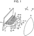
FIG. 1] FIG. 1 is a perspective view showing a lamp for vehicles according to an embodiment. - [
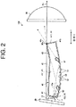
FIG. 2] FIG. 2 is a cross-sectional view showing a vehicle light guide according to the embodiment. - [
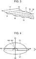
FIG. 3] FIG. 3 is an enlarged perspective view showing a light diffusing part formed on the vehicle light guide. - [
FIG. 4] FIG. 4 is a diagram showing one example of an ADB light distribution pattern projected on a screen in front of a vehicle in the lamp for vehicles according to the embodiment. - In the following, an embodiment is described in detail with reference to the accompanying drawings.
- The present invention is not limited by the embodiment. In addition, components in the following embodiment include those that can be easily replaced by those skilled in the art, or those that are substantially the same. In the following description, each of front and rear directions, up and down directions, and left and right directions is a direction in a state that a light guide for vehicles and a lamp for vehicles are mounted in a vehicle, and indicates a direction when a traveling direction of the vehicle is viewed from a driver's seat. In the present embodiment, it is assumed that the up and down directions are in parallel to a vertical direction, and the left and right directions are a horizontal direction. In the following description, the left and right directions of the vehicle are referred to as a "direction X", and the front and rear directions of the vehicle are referred to as a "direction Y".
-
FIG. 1 is a perspective view showing a lamp for vehicles according to an embodiment, andFIG. 2 is a cross-sectional view showing a light guide for vehicles according to the embodiment.FIG. 2 shows a cross section of a central part of the light guide for vehicles in the direction X. As shown inFIG. 1 , avehicle lamp 100 includes a plurality oflight sources 10, alight source substrate 20, aprojection lens 30, and avehicle light guide 40. In the present embodiment, thevehicle lamp 100 irradiates, in a predetermined irradiation direction, an adaptive device beam (ADB) pattern (hereinafter, referred to as an "ADB light distribution pattern") in which a high beam pattern is dynamically adjusted in such a way that an oncoming vehicle or a preceding vehicle is not dazzled. Thevehicle lamp 100 is housed in a lamp chamber formed of an unillustrated lamp housing and an unillustrated lamp lens (for example, a transparent outer lens or the like). Note that other lamp units such as an unillustrated low beam lamp unit and an unillustrated high beam lamp unit may be disposed in the lamp chamber. - The plurality of
light sources 10 are, for example, semiconductor type light sources such as LEDs, OELs, and OLEDs (organic ELs). The plurality oflight sources 10 are mounted on thelight source substrate 20. As schematically shown inFIG. 1 , the plurality oflight sources 10 are disposed side by side along the direction X in a vehicle-mounted state. As shown inFIG. 2 , each of thelight sources 10 has a light emitting surface 11 that emits light in such a way as to form a Lambertian distribution. When thevehicle lamp 100 is mounted on a vehicle, the light emitting surface 11 faces the front side. - The
projection lens 30 is disposed on the front side of the vehicle with respect to the plurality oflight sources 10, thelight source substrate 20, and thevehicle light guide 40. Theprojection lens 30 is supported by, for example, an unillustrated lens holder. As shown inFIG. 2 , theprojection lens 30 has afocal point 30a and an optical axis AX. Theprojection lens 30 irradiates light emitted from thelight source 10 and guided through thevehicle light guide 40 toward the front side of the vehicle. - The
vehicle light guide 40 is disposed between the plurality oflight sources 10 and theprojection lens 30, and guides light from the plurality oflight sources 10 toward theprojection lens 30. Thevehicle light guide 40 is formed by, for example, resin molding. As shown inFIGS. 1 and2 , thevehicle light guide 40 includes a plurality ofincident surfaces 41, a plurality oflight guide parts 42, a mergingpart 43, and an exit surface 44. - The plurality of
incident surfaces 41 are disposed side by side along the direction X. Each of theincident surfaces 41 is disposed side by side along the direction X in association with each of thelight sources 10. Each of thelight guide parts 42 extends from each of theincident surfaces 41 toward theprojection lens 30. The mergingpart 43 is a portion where each of thelight guide parts 42 merges at an end thereof on a side opposite to theincident surface 41. As shown inFIG. 1 , themerging part 43 is formed with a mountingpart 40a projecting in the direction X. Thevehicle light guide 40 is fixed to an unillustrated mounting member by themounting part 40a within the lamp chamber. - As shown in
FIG. 2 , thelight guide part 42 and the mergingpart 43 form a reflective surface 45 that reflects light incident from theincident surface 41 toward the exit surface 44. The reflective surface 45 includes an upper reflective surface 451 located on the upper side in the vertical direction, and a lower reflective surface 452 located on the lower side in the vertical direction. In the present embodiment, light reflected on the lower reflective surface 452 is output from the exit surface 44 with respect to a vicinity of anupper end 44a of the exit surface 44 in the vertical direction as a focal point. - The exit surface 44 is formed on an end surface of the merging
part 43 on theprojection lens 30 side. The exit surface 44 outputs, toward theprojection lens 30, light from each of thelight sources 10, which is guided from each of theincident surfaces 41 through each of thelight guide parts 42 and the mergingpart 43. In the present embodiment, as shown inFIG. 1 , the exit surface 44 is divided into a plurality of sections. The exit surface 44 includes a central exit surface 441 located at a central part in the direction X, and lateral exit surfaces 442 located laterally in the direction X with respect to the central exit surface 441. The central exit surface 441 and the lateral exit surfaces 442 are integrally formed on the end surface of themerging part 43. - The central exit surface 441 is formed at a position associated with four centrally arranged
light sources 10 among the plurality oflight sources 10. Further, as shown inFIG. 2 , the central exit surface 441 is disposed in the vicinity of thefocal point 30a of theprojection lens 30. On the other hand, as shown inFIG. 1 , the lateral exit surface 442 extends toward the front side in the direction Y, as the distance thereof from the central exit surface 441 increases. Specifically, the lateral exit surface 442 is located forward in the direction Y with respect to the central exit surface 441. Therefore, the central exit surface 441 is disposed closer to thefocal point 30a of theprojection lens 30 than the lateral exit surface 442. In the present embodiment, as shown inFIG. 2 , a vicinity of anupper end 44a of the central exit surface 441 is disposed at a position where the vicinity overlaps thefocal point 30a of theprojection lens 30. Anupper end 44a of the lateral exit surface 442 is located farther from thefocal point 30a than theupper end 44a of the central exit surface 441 in the direction X and the direction Y (horizontal direction), but is disposed along a meridional image plane in the vertical direction. Specifically, theupper end 44a of the exit surface 44 is disposed in the vicinity of thefocal point 30a of theprojection lens 30 in the vertical direction. Further, as shown inFIG. 2 , alower end 44b of the exit surface 44 in the vertical direction is disposed closer to theprojection lens 30 than theupper end 44a in the vertical direction. In other words, the exit surface 44 extends with an inclination toward theprojection lens 30, as the exit surface 44 extends from theupper end 44a toward thelower end 44b. - Light incident from the
light source 10 passes through the vehiclelight guide 40 while being reflected on the upper reflective surface 451 and the lower reflective surface 452, is output from the exit surface 44, and is irradiated toward the front side of the vehicle via theprojection lens 30. In this way, light irradiated toward the front side of the vehicle via theprojection lens 30 forms an ADB light distribution pattern as described above.FIG. 4 is a diagram showing one example of the ADB light distribution pattern projected on a screen in front of a vehicle in the vehicle lamp according to the embodiment. InFIG. 4 , the reference numeral "VU-VD" indicates a vertical line of the screen, and the reference numeral "HL-HR" indicates a horizontal line on the left and right of the screen. As shown inFIG. 4 , an ADB light distribution pattern P1 irradiates the upper side of a low beam light distribution pattern LP that is irradiated from an unillustrated low beam lamp unit. The ADB light distribution pattern P1 passes through theincident surface 41 and thelight guide part 42 formed in association with each of thelight sources 10, is output from the exit surface 44, and is divided into a plurality of patterns (not shown), which are irradiated from theprojection lens 30. Further, in the present embodiment, the ADB light distribution pattern P1 forms a high beam light distribution pattern by irradiation in a range shown inFIG.4 . Alternatively, thevehicle lamp 100 may separately include a high beam lamp unit for acquiring a high beam light distribution pattern. - As shown in
FIG. 4 , the ADB light distribution pattern P1 includes a hot zone Hz1 as a maximum luminous intensity band or a maximum illuminance band. In the present embodiment, after having been reflected on the lower reflective surface 452 of the vehiclelight guide 40, light that passes through thefocal point 30a or its vicinity and is irradiated from theprojection lens 30 irradiates the hot zone Hz1. Further, after having been reflected on each reflective surface of the vehiclelight guide 40, light that is output from a portion other than thefocal point 30a or its vicinity and is irradiated from theprojection lens 30 irradiates the periphery of the hot zone Hz1. - In the
vehicle lamp 100 according to the present embodiment, by individually switching lighting states of the plurality oflight sources 10, it is possible to adjust a range of light that passes through each of the incident surfaces 41 and each of thelight guide parts 42 from each of thelight sources 10, and is irradiated from theprojection lens 30. In other words, by turning off a part of the plurality oflight sources 10 disposed along the direction X, it is possible to prevent a part of a plurality of divided patterns of the ADB light distribution pattern P1 shown inFIG. 4 from being irradiated. Thus, it is possible to set a predetermined range in a horizontal direction of the screen, as a range in which light is not irradiated. Consequently, when an oncoming vehicle or a preceding vehicle is detected in front of the vehicle, it is possible to prevent the oncoming vehicle or the preceding vehicle from being dazzled by preventing light from being irradiated in an area of the ADB light distribution pattern P1 where the oncoming vehicle or the preceding vehicle is present. - The structure of the vehicle
light guide 40 is described in more detail with reference toFIGS. 2 and3. FIG. 3 is an enlarged perspective view showing a light diffusing part formed on the vehicle light guide. As shown inFIGS. 2 and3 , alight diffusing part 50 that diffuses light is formed, within a predetermined area, on the lower reflective surface 452 where thelight guide part 42 continuing to the central exit surface 441 is formed. - The
light diffusing part 50 is formed in a predetermined area of the reflective surface 45 extending from theincident surface 41 to the central exit surface 441. In the present embodiment, thelight diffusing part 50 is formed in the entire area of the lower reflective surface 452 in the direction X within a predetermined range. As shown inFIG. 2 , the predetermined range is a range from anintersection 61 between acentral axis 10a of light emitted from thelight source 10 and the lower reflective surface 452, to anintersection 62 between a line L1 along a half-value angle θ of the light emitted from thelight source 10 and the lower reflective surface 452. The half-value angle θ is an angle at which an intensity of light emitted from thelight source 10 is halved, and is 60 ° in thelight source 10 that forms a Lambertian distribution. - The
light diffusing part 50 includes a plurality ofconvex parts 51 and a plurality ofconcave parts 52. In thelight diffusing part 50, theconvex part 51 and theconcave part 52 are disposed continuously in order. Theconvex part 51 and theconcave part 52 adjacent to each other are smoothly connected to each other. Specifically, a portion (concave part 52 in the present embodiment) adjacent to theconvex part 51, and a portion (convex part 51 in the present embodiment) adjacent to theconcave part 52 do not have corner portions (edges), and are formed to be a smooth continuous surface. Thus, as shown inFIGS. 2 and3 , thelight diffusing part 50 is formed into a waveform shape by the continuousconvex parts 51 andconcave parts 52. In this configuration, among the light incident on the vehicle light guide 40 from thelight source 10, light reflected on thelight diffusing part 50 is diffused by the plurality ofconvex parts 51 and the plurality ofconcave parts 52, as shown by solid arrows inFIG. 2 . Consequently, a vertical thickness of the hot zone Hz1 formed by reflected light that is reflected on the lower reflective surface 452 and passes through thefocal point 30a is increased by diffusion of reflected light on thelight diffusing part 50. - In
FIG. 4 , a hot zone Hz0 shown by the broken line is a hot zone, as a comparative example, in a case where the lower reflective surface 452 is irradiated with the ADB light distribution pattern P1 via a vehicle light guide having a shape extending flat without thelight diffusing part 50, specifically, without the plurality ofconvex parts 51 and the plurality ofconcave parts 52. As illustrated, a vertical thickness A of the hot zone Hz1 in thevehicle lamp 100 according to the embodiment is larger than a thickness B of the hot zone Hz0 as a comparative example. Specifically, the vertical thickness of the hot zone Hz1 in thevehicle lamp 100 according to the embodiment increases, as compared with the comparative example. In this way, by forming thelight diffusing part 50 on the vehiclelight guide 40, it becomes possible to adjust the vertical thickness of the hot zone Hz1, and consequently, it is possible to form the hot zone Hz1 of a desired thickness. Therefore, the pitch and the height of the plurality ofconvex parts 51 and the plurality ofconcave parts 52 of thelight diffusing part 50 may be determined according to a value of the vertical thickness A of the hot zone Hz1. - As described above, the
vehicle lamp 100 according to the embodiment includes thelight source 10, theprojection lens 30, and the vehiclelight guide 40. The vehiclelight guide 40 according to the embodiment is the vehiclelight guide 40 that guides light from thelight source 10 toward theprojection lens 30, and includes theincident surface 41 on which light from thelight source 10 is incident, the reflective surface 45 that reflects light incident from theincident surface 41, and the exit surface 44 that outputs light reflected on the reflective surface 45. The reflective surface 45 includes thelight diffusing part 50 where the plurality ofconvex parts 51 and the plurality ofconcave parts 52 that diffuse light are formed. - In this configuration, it is possible to diffuse light from the
light source 10 by thelight diffusing part 50 formed on the reflective surface 45, and sufficiently secure a vertical thickness of a predetermined area (hot zone Hz1 according to the present embodiment) of a light distribution pattern (ADB light distribution pattern P1 according to the present embodiment), which is formed by thevehicle lamp 100 including the vehiclelight guide 40. By securing a thickness of the predetermined area, it is possible to reduce a difference in luminous intensity and a difference in illuminance between the predetermined area and other areas. Specifically, it is possible to suppress a sharp change in luminous intensity and illuminance between the predetermined area and the other areas, and smoothly continue the predetermined area and the other areas. Consequently, for example, even when a predetermined area of a light distribution pattern is shifted due to vertical aiming of thevehicle lamp 100 in the vertical direction, misalignment of each component, or the like, a desired luminous intensity and illuminance can be acquired more reliably within a target range. Therefore, it becomes possible to acquire a desired light distribution performance. In addition, it becomes possible to more reliably acquire a light distribution pattern in accordance with the regulations. - Further, the
light diffusing part 50 is formed on the reflective surface 45 (lower reflective surface 452) for forming the hot zone Hz 1 of the ADB light distribution pattern P1 irradiated from theprojection lens 30. - In this configuration, it is possible to secure a vertical thickness of the hot zone Hz1 having a maximum luminous intensity band or a maximum illuminance band on the ADB light distribution pattern P1, and in which the thickness tends to reduce by light collection. It is possible to suppress a sharp change in luminous intensity and illuminance between the hot zone Hz1 and other areas, and smoothly continue the hot zone Hz1 and the other areas. Consequently, for example, even when the hot zone Hz1 is shifted due to vertical aiming of the
vehicle lamp 100 in the vertical direction, misalignment of each component, or the like, a desired luminous intensity and illuminance can be more reliably acquired in a target range. Therefore, it becomes possible to acquire a desired light distribution performance. - Further, the
light diffusing part 50 is connected in such a way that theconvex part 51 or theconcave part 52, and a portion adjacent to theconvex part 51 or theconcave part 52 are formed to be a smooth continuous surface. - In this configuration, it is possible to prevent a corner portion (edge) from being formed on the plurality of
convex parts 51 and the plurality ofconcave parts 52 of thelight diffusing part 50. Consequently, it becomes possible to easily form the vehiclelight guide 40 by resin molding. - Further, the
light diffusing part 50 is formed between theintersection 61 between thecentral axis 10a of light emitted from thelight source 10 and the reflective surface 45 (lower reflective surface 452), and theintersection 62 between the line L1 along the half-value angle θ of the light emitted from thelight source 10 and the reflective surface 45 (lower reflective surface 452). - In this configuration, it is possible to diffuse light having a sufficiently high intensity among the light emitted from the
light source 10 by thelight diffusing part 50, and sufficiently acquire a luminous intensity or illuminance of the hot zone Hz1, while securing a vertical thickness of the hot zone Hz1. - Further, a plurality of the incident surfaces 41 are formed side by side along the left and right directions of the vehicle in association with each of the plurality of
light sources 10 disposed side by side along the left and right directions. The exit surface 44 includes the central exit surface 441 formed at a central part in the left and right directions, and the lateral exit surfaces 442 formed laterally in the left and right directions with respect to the central exit surface 441. The central exit surface 441 is formed closer to thefocal point 30a of theprojection lens 30 than the lateral exit surface 442. Thelight diffusing part 50 is formed on the reflective surface 45 extending from theincident surface 41 to the central exit surface 441. - In this configuration, it is possible to diffuse light having a high light intensity and output from the central exit surface 441 disposed in the vicinity of the
focal point 30a of theprojection lens 30 by thelight diffusing part 50. Consequently, it is possible to reliably secure a vertical thickness of the hot zone Hz1. - Further, the vehicle lamp additionally includes a plurality of the
light guide parts 42, each of which extends from theincident surface 41 and includes the reflective surface 45, and the mergingpart 43 where the plurality oflight guide parts 42 merge. The central exit surface 441 and the lateral exit surface 442 are integrally formed on an end surface of the mergingpart 43 on theprojection lens 30 side. - In this configuration, it is possible to suppress occurrence of spots and streaks in the ADB light distribution pattern P1, as compared with a case where the central exit surface 441 and the lateral exit surface 442 are formed on separate members.
- Further, the
upper end 44a of the exit surface 44 is disposed in the vicinity of thefocal point 30a of theprojection lens 30 in the vertical direction, and thelower end 44b is disposed closer to theprojection lens 30 than theupper end 44a. - In this configuration, it is possible to output light obliquely upward from the exit surface 44. Consequently, it is possible to satisfactorily transmit light output from the exit surface 44, whose major part is located below the
focal point 30a of theprojection lens 30 in the vertical direction, toward theprojection lens 30, and it becomes possible to improve light use efficiency. - In the present embodiment, the
light diffusing part 50 is formed into a waveform shape by the plurality ofconvex parts 51 and the plurality ofconcave parts 52. However, as far as light from thelight source 10 can be appropriately diffused, thelight diffusing part 50 may have another shape. For example, thelight diffusing part 50 may be formed by either one of the plurality ofconvex parts 51 and the plurality ofconcave parts 52. For example, thelight diffusing part 50 may be formed by continuously forming theconvex part 51 and a flat part 53 (see the broken line inFIG. 3 ). Theflat part 53 has an elliptical shape similar to the shape in a range other than the portion of the lower reflective surface 452 where thelight diffusing part 50 is formed. Further, thelight diffusing part 50 may be formed by continuously forming theconcave part 52 and theflat part 53. Also in this case, in order to secure manufacturing easiness of the vehiclelight guide 40, the convex part 51 (or the concave part 52) and theflat part 53 may preferably be connected to be a smooth continuous surface in such a way that a corner portion is not formed. - Further, in the present embodiment, the
light diffusing part 50 is formed in the entire area of the lower reflective surface 452 in the direction X within a predetermined range. Alternatively, thelight diffusing part 50 may be formed only in a part of a range of the lower reflective surface 452 in the direction X within a predetermined range. Further alternatively, thelight diffusing part 50 may not be formed in the entire length of a range between theintersection 61 between thecentral axis 10a of thelight source 10 and the reflective surface 45 (lower reflective surface 452), and theintersection 62 between the line L1 along the half-value angle θ of the light from thelight source 10 and the reflective surface 45 (lower reflective surface 452), but may be formed only on a part of the range. - Further, in the present embodiment, the
light diffusing part 50 is formed on the lower reflective surface 452 of thelight guide part 42 continuing to the central exit surface 441. Alternatively, thelight diffusing part 50 may be formed only on a part of thelight guide part 42 continuing to the central exit surface 441, or may be formed on thelight guide part 42 continuing to the lateral exit surface 442. - Further, in the present embodiment, the
light diffusing part 50 is formed on the lower reflective surface 452 for forming the hot zone Hz1. Alternatively, thelight diffusing part 50 may be formed on any part of the reflective surface 45 for forming an area other than the hot zone Hz 1 on the ADB light distribution pattern P1. Further, in the present embodiment, thelight diffusing part 50 diffuses light to secure a vertical thickness of a predetermined area on a light distribution pattern in the vertical direction. Alternatively, thelight diffusing part 50 may be configured to diffuse light to secure a thickness of the predetermined area in the horizontal direction or in any direction. - Further, a reflective member that reflects light more advantageously may be formed on a surface of the vehicle
light guide 40 at a position where thelight diffusing part 50 is formed. The reflective member may be formed by, for example, vapor deposition. -
- 10 Light source
- 10a Central axis
- 11 Light emitting surface
- 20 Light source substrate
- 30a Focal point
- 30 Projection lens
- 40 Vehicle light guide
- 40a Mounting part
- 41 Incident surface
- 42 Light guide part
- 43 Merging part
- 44 Exit surface
- 441 Central exit surface
- 442 Lateral exit surface
- 45 Reflective surface
- 451 Upper reflective surface
- 452 Lower reflective surface
- 50 Light diffusing part
- 51 Convex part
- 52 Concave part
- 53 Flat part
- 100 Vehicle lamp
Claims (8)
- A light guide for vehicles that guides light from a light source toward a projection lens, comprising:an incident surface on which light from the light source is incident;a reflective surface that reflects light incident from the incident surface; andan exit surface that outputs light reflected on the reflective surface, whereinthe reflective surface includes, on at least a part thereof, a light diffusing part where at least either one of a plurality of convex parts and a plurality of concave parts that diffuse light are formed.
- The light guide for vehicles according to claim 1, wherein
the light diffusing part is formed on the reflective surface for forming a hot zone of a light distribution pattern irradiated from the projection lens. - The light guide for vehicles according to claim 1, wherein
the light diffusing part is connected in such a way that the convex part or the concave part, and a portion adjacent to the convex part or the concave part are formed to be a smooth continuous surface. - The light guide for vehicles according to claim 1, wherein
the light diffusing part is formed on at least a part between an intersection between a central axis of light emitted from the light source and the reflective surface, and an intersection between a line along a half-value angle of light emitted from the light source and the reflective surface. - The light guide for vehicles according to claim 1, wherein
a plurality of the incident surfaces are formed side by side along left and right directions of a vehicle in association with each of a plurality of the light sources disposed side by side along the left and right directions,
the exit surface includes a central exit surface formed at a central part in the left and right directions, and lateral exit surfaces formed laterally in the left and right directions with respect to the central exit surface,
the central exit surface is formed closer to a focal point of the projection lens than the lateral exit surface, and
the light diffusing part is formed on the reflective surface extending from the incident surface to the central exit surface. - The light guide for vehicles according to claim 5, further comprising
a plurality of light guide parts extending from the incident surface and including the reflective surface, and
a merging part where the plurality of light guide parts merge, wherein
the central exit surface and the lateral exit surface are integrally formed on an end surface of the merging part on a side of the projection lens. - A lamp for vehicles comprising:a light source;a projection lens; andthe light guide for vehicles according to claim 1.
- The lamp for vehicles according to claim 7, wherein
the exit surface includes an upper end disposed in the vicinity of a focal point of the projection lens in a vertical direction, and a lower end disposed closer to the projection lens than the upper end.
Applications Claiming Priority (2)
| Application Number | Priority Date | Filing Date | Title |
|---|---|---|---|
| JP2018191631A JP7143716B2 (en) | 2018-10-10 | 2018-10-10 | Vehicle light guide and vehicle lamp |
| PCT/JP2019/038254 WO2020075536A1 (en) | 2018-10-10 | 2019-09-27 | Light guide for vehicles, and lamp for vehicles |
Publications (2)
| Publication Number | Publication Date |
|---|---|
| EP3865766A1 true EP3865766A1 (en) | 2021-08-18 |
| EP3865766A4 EP3865766A4 (en) | 2022-07-20 |
Family
ID=70164924
Family Applications (1)
| Application Number | Title | Priority Date | Filing Date |
|---|---|---|---|
| EP19871997.3A Withdrawn EP3865766A4 (en) | 2018-10-10 | 2019-09-27 | Light guide for vehicles, and lamp for vehicles |
Country Status (5)
| Country | Link |
|---|---|
| US (1) | US11603972B2 (en) |
| EP (1) | EP3865766A4 (en) |
| JP (1) | JP7143716B2 (en) |
| CN (1) | CN113167452B (en) |
| WO (1) | WO2020075536A1 (en) |
Cited By (1)
| Publication number | Priority date | Publication date | Assignee | Title |
|---|---|---|---|---|
| EP4664000A1 (en) * | 2024-06-13 | 2025-12-17 | ZKW Group GmbH | Lighting device for a vehicle headlamp |
Families Citing this family (7)
| Publication number | Priority date | Publication date | Assignee | Title |
|---|---|---|---|---|
| DE102019108312A1 (en) * | 2019-03-29 | 2020-10-01 | HELLA GmbH & Co. KGaA | Communication light device for vehicles |
| JP7478030B2 (en) * | 2020-06-01 | 2024-05-02 | 株式会社小糸製作所 | Vehicle lighting fixtures |
| WO2021246065A1 (en) * | 2020-06-02 | 2021-12-09 | ミネベアミツミ株式会社 | Illumination device |
| JP7530794B2 (en) * | 2020-10-02 | 2024-08-08 | 株式会社小糸製作所 | Lighting unit |
| FR3125858B1 (en) * | 2021-07-30 | 2023-10-06 | Valeo Vision | Light module with sources with maximized emissive part |
| EP4614060A1 (en) * | 2024-03-08 | 2025-09-10 | PO LIGHTING CZECH s.r.o. | Light guide for a motor vehicle illumination device for improving light homogeneity |
| WO2026014414A1 (en) * | 2024-07-10 | 2026-01-15 | 株式会社小糸製作所 | Vehicle headlight |
Family Cites Families (18)
| Publication number | Priority date | Publication date | Assignee | Title |
|---|---|---|---|---|
| JP4049624B2 (en) | 2001-07-27 | 2008-02-20 | 株式会社エンプラス | Surface light source device, image display device, and light guide plate |
| JP4737777B2 (en) | 2001-07-27 | 2011-08-03 | 株式会社エンプラス | Surface light source device, image display device, and light guide plate |
| DE102006044640A1 (en) * | 2006-09-19 | 2008-03-27 | Schefenacker Vision Systems Germany Gmbh | Lighting unit for high and low beam generation |
| JP5091808B2 (en) * | 2008-09-02 | 2012-12-05 | 株式会社小糸製作所 | Vehicle lighting |
| JP5229023B2 (en) | 2009-03-12 | 2013-07-03 | スタンレー電気株式会社 | Vehicle lighting |
| JP5567435B2 (en) * | 2010-09-06 | 2014-08-06 | 株式会社小糸製作所 | Vehicle lighting |
| JP5640306B2 (en) * | 2011-03-14 | 2014-12-17 | スタンレー電気株式会社 | Lamp unit |
| DE102011077636A1 (en) * | 2011-04-27 | 2011-11-03 | Automotive Lighting Reutlingen Gmbh | Light module for head lamp system of motor vehicle i.e. motor car, has sub modules separately controlled to generate set of strip-shaped segments of spot distribution, where strip-shaped segments are complement to spot distribution |
| JP2012256491A (en) | 2011-06-08 | 2012-12-27 | Stanley Electric Co Ltd | Vehicle lamp unit |
| AT513341B1 (en) * | 2012-09-03 | 2015-06-15 | Zizala Lichtsysteme Gmbh | Lighting unit for a headlight |
| AT514333B1 (en) | 2013-06-25 | 2014-12-15 | Zizala Lichtsysteme Gmbh | Headlights for vehicles |
| FR3012203B1 (en) | 2013-10-23 | 2015-10-30 | Valeo Vision | LIGHTING DEVICE COMPRISING A GUIDE OF LUMINOUS RAYS |
| US9803821B2 (en) | 2014-01-17 | 2017-10-31 | Mitsubishi Electric Corporation | Vehicle-mounted headlamp |
| FR3033621B1 (en) | 2015-03-13 | 2017-04-21 | Valeo Iluminacion Sa | LIGHT DEVICE WITH OPTICAL GUIDES |
| WO2016162921A1 (en) | 2015-04-06 | 2016-10-13 | 三菱電機株式会社 | Headlight light source and headlight |
| FR3038696B1 (en) | 2015-07-10 | 2022-02-18 | Valeo Vision | LIGHT MODULE FOR LIGHTING AND/OR SIGNALING OF A MOTOR VEHICLE |
| AT517523B1 (en) * | 2015-07-28 | 2017-09-15 | Zkw Group Gmbh | Lighting device for a motor vehicle headlight |
| JP2017212037A (en) | 2016-05-23 | 2017-11-30 | スタンレー電気株式会社 | Vehicle headlamp |
-
2018
- 2018-10-10 JP JP2018191631A patent/JP7143716B2/en active Active
-
2019
- 2019-09-27 CN CN201980081427.XA patent/CN113167452B/en active Active
- 2019-09-27 EP EP19871997.3A patent/EP3865766A4/en not_active Withdrawn
- 2019-09-27 WO PCT/JP2019/038254 patent/WO2020075536A1/en not_active Ceased
- 2019-09-27 US US17/284,258 patent/US11603972B2/en active Active
Cited By (1)
| Publication number | Priority date | Publication date | Assignee | Title |
|---|---|---|---|---|
| EP4664000A1 (en) * | 2024-06-13 | 2025-12-17 | ZKW Group GmbH | Lighting device for a vehicle headlamp |
Also Published As
| Publication number | Publication date |
|---|---|
| EP3865766A4 (en) | 2022-07-20 |
| CN113167452A (en) | 2021-07-23 |
| JP7143716B2 (en) | 2022-09-29 |
| CN113167452B (en) | 2023-07-28 |
| US20210381668A1 (en) | 2021-12-09 |
| JP2020061266A (en) | 2020-04-16 |
| US11603972B2 (en) | 2023-03-14 |
| WO2020075536A1 (en) | 2020-04-16 |
Similar Documents
| Publication | Publication Date | Title |
|---|---|---|
| US11603972B2 (en) | Light guide for vehicles, and lamp for vehicles | |
| US10215357B2 (en) | Vehicular lamp | |
| KR101423874B1 (en) | Vehicular lamp | |
| JP5939491B2 (en) | LED projection module | |
| KR101371565B1 (en) | Vehicular lamp | |
| EP2693105B1 (en) | Vehicle lighting unit | |
| KR100749574B1 (en) | Vehicular lamp | |
| KR101163819B1 (en) | License plate lamp | |
| EP3012522B1 (en) | Vehicle lighting unit | |
| US12560293B2 (en) | Vehicle light-guiding body and vehicle lighting unit | |
| KR102109910B1 (en) | Vehicle headlamp | |
| CN112135998A (en) | Vehicle lamps | |
| CN115769021B (en) | Vehicle lights | |
| JP2005251435A (en) | Vehicle headlamp | |
| JP2022028514A (en) | Vehicular headlight | |
| US20220186898A1 (en) | Lamp for vehicle | |
| JP2020505734A (en) | Lighting equipment for automotive floodlights | |
| JP5381351B2 (en) | Vehicle lighting | |
| JP6134111B2 (en) | Vehicle lighting | |
| EP4130570A1 (en) | Vehicle light guide body and vehicle lighting unit | |
| JP7234681B2 (en) | vehicle lamp | |
| KR20250101713A (en) | Lamp for vehicle | |
| CN121993755A (en) | Vehicle lights | |
| JP2017130309A (en) | Vehicular headlamp |
Legal Events
| Date | Code | Title | Description |
|---|---|---|---|
| STAA | Information on the status of an ep patent application or granted ep patent |
Free format text: STATUS: THE INTERNATIONAL PUBLICATION HAS BEEN MADE |
|
| PUAI | Public reference made under article 153(3) epc to a published international application that has entered the european phase |
Free format text: ORIGINAL CODE: 0009012 |
|
| STAA | Information on the status of an ep patent application or granted ep patent |
Free format text: STATUS: REQUEST FOR EXAMINATION WAS MADE |
|
| 17P | Request for examination filed |
Effective date: 20210409 |
|
| AK | Designated contracting states |
Kind code of ref document: A1 Designated state(s): AL AT BE BG CH CY CZ DE DK EE ES FI FR GB GR HR HU IE IS IT LI LT LU LV MC MK MT NL NO PL PT RO RS SE SI SK SM TR |
|
| DAV | Request for validation of the european patent (deleted) | ||
| DAX | Request for extension of the european patent (deleted) | ||
| A4 | Supplementary search report drawn up and despatched |
Effective date: 20220620 |
|
| RIC1 | Information provided on ipc code assigned before grant |
Ipc: F21S 41/663 20180101ALI20220614BHEP Ipc: F21S 41/255 20180101ALI20220614BHEP Ipc: F21S 41/25 20180101ALI20220614BHEP Ipc: F21S 41/147 20180101ALI20220614BHEP Ipc: F21Y 115/15 20160101ALI20220614BHEP Ipc: F21Y 115/10 20160101ALI20220614BHEP Ipc: F21W 102/155 20180101ALI20220614BHEP Ipc: F21V 8/00 20060101ALI20220614BHEP Ipc: F21S 41/24 20180101AFI20220614BHEP |
|
| STAA | Information on the status of an ep patent application or granted ep patent |
Free format text: STATUS: EXAMINATION IS IN PROGRESS |
|
| 17Q | First examination report despatched |
Effective date: 20230512 |
|
| GRAP | Despatch of communication of intention to grant a patent |
Free format text: ORIGINAL CODE: EPIDOSNIGR1 |
|
| STAA | Information on the status of an ep patent application or granted ep patent |
Free format text: STATUS: GRANT OF PATENT IS INTENDED |
|
| INTG | Intention to grant announced |
Effective date: 20241010 |
|
| STAA | Information on the status of an ep patent application or granted ep patent |
Free format text: STATUS: THE APPLICATION IS DEEMED TO BE WITHDRAWN |
|
| 18D | Application deemed to be withdrawn |
Effective date: 20250211 |