EP3865685A1 - Steam power plant and method for converting an existing steam power plant - Google Patents
Steam power plant and method for converting an existing steam power plant Download PDFInfo
- Publication number
- EP3865685A1 EP3865685A1 EP20156798.9A EP20156798A EP3865685A1 EP 3865685 A1 EP3865685 A1 EP 3865685A1 EP 20156798 A EP20156798 A EP 20156798A EP 3865685 A1 EP3865685 A1 EP 3865685A1
- Authority
- EP
- European Patent Office
- Prior art keywords
- boiler
- power plant
- hot air
- steam power
- energy store
- Prior art date
- Legal status (The legal status is an assumption and is not a legal conclusion. Google has not performed a legal analysis and makes no representation as to the accuracy of the status listed.)
- Withdrawn
Links
Images
Classifications
-
- F—MECHANICAL ENGINEERING; LIGHTING; HEATING; WEAPONS; BLASTING
- F01—MACHINES OR ENGINES IN GENERAL; ENGINE PLANTS IN GENERAL; STEAM ENGINES
- F01K—STEAM ENGINE PLANTS; STEAM ACCUMULATORS; ENGINE PLANTS NOT OTHERWISE PROVIDED FOR; ENGINES USING SPECIAL WORKING FLUIDS OR CYCLES
- F01K3/00—Plants characterised by the use of steam or heat accumulators, or intermediate steam heaters, therein
- F01K3/18—Plants characterised by the use of steam or heat accumulators, or intermediate steam heaters, therein having heaters
- F01K3/20—Plants characterised by the use of steam or heat accumulators, or intermediate steam heaters, therein having heaters with heating by combustion gases of main boiler
-
- F—MECHANICAL ENGINEERING; LIGHTING; HEATING; WEAPONS; BLASTING
- F22—STEAM GENERATION
- F22B—METHODS OF STEAM GENERATION; STEAM BOILERS
- F22B31/00—Modifications of boiler construction, or of tube systems, dependent on installation of combustion apparatus; Arrangements of dispositions of combustion apparatus
- F22B31/0007—Modifications of boiler construction, or of tube systems, dependent on installation of combustion apparatus; Arrangements of dispositions of combustion apparatus with combustion in a fluidized bed
- F22B31/0076—Controlling processes for fluidized bed boilers not related to a particular type
-
- Y—GENERAL TAGGING OF NEW TECHNOLOGICAL DEVELOPMENTS; GENERAL TAGGING OF CROSS-SECTIONAL TECHNOLOGIES SPANNING OVER SEVERAL SECTIONS OF THE IPC; TECHNICAL SUBJECTS COVERED BY FORMER USPC CROSS-REFERENCE ART COLLECTIONS [XRACs] AND DIGESTS
- Y02—TECHNOLOGIES OR APPLICATIONS FOR MITIGATION OR ADAPTATION AGAINST CLIMATE CHANGE
- Y02E—REDUCTION OF GREENHOUSE GAS [GHG] EMISSIONS, RELATED TO ENERGY GENERATION, TRANSMISSION OR DISTRIBUTION
- Y02E60/00—Enabling technologies; Technologies with a potential or indirect contribution to GHG emissions mitigation
- Y02E60/14—Thermal energy storage
Definitions
- ETES electro-thermal energy storage
- Thermal energy storage systems are currently hardly commercially available in large power plants, or these energy storage systems are only planned as an additive system parallel to the existing cycle.
- An additional waste heat boiler (English Heat Recovery Steam Generator, or HRSG for short) is installed to transfer the stored heat into the water / steam cycle. This waste heat boiler is associated with considerable additional financial expense.
- the invention is based on the object of enabling an efficient and cost-effective integration of a thermal energy store in a steam power plant, in particular in an existing steam power plant.
- a steam power plant comprising a steam generating unit and a thermal energy store, the steam generating unit having a fossil-fired boiler with at least one hot air inlet, the energy store having an air inlet and an air outlet, and a hot air line being connected to the air outlet, which in the at least one hot air inlet of the boiler opens.
- the object is also achieved according to the invention by a method for converting a steam power plant by adding an already existing steam generating unit which is a fossil fuel Has boiler with at least one hot air inlet, is supplemented by a thermal energy store, the boiler being operated with hot air from the energy store.
- the invention is based on the consideration, so that an optimum is achieved both on the cost side and on the efficiency side, to propose a connection of the thermal energy store to an existing steam power plant, the integration of the energy store being designed in such a way that it is based on as many existing components as possible in the Power plant falls back.
- the additional investment costs must be kept to a minimum. It is particularly important to be able to continue using the relatively expensive boiler.
- Thermal energy is stored in the energy store using air as a carrier medium. When the energy storage device is discharged or discharged, the air is passed through the energy storage device, the air absorbing thermal energy from the energy storage device and this is then fed as hot air to the fossil-fueled boiler.
- the hot air stream has a temperature of over 700 ° C, in particular of approx. 800 ° C. Partial admixture of the hot air can gradually save fossil fuel for the boiler operation.
- the energy store is preferably a rock store.
- An electrothermal energy store (ETES) is based on the principle of a kind of "giant hair dryer” through which a stream of hot air is generated. This is done with the help of heating elements and a fan. The fan is designed in such a way that the pressure is sufficient to convey the air along the entire hot air path.
- ETES electrothermal energy store
- In charging mode excess electricity is taken from the power grid and converted into heat via resistance heating implemented. This heat is absorbed by an air stream and conducted as hot air to the stone storage tank. In the cold storage tank, the sensible heat in the air is transferred to the amount of rock. The cooled air is fed back to the heating elements in circulation mode via a fan. This charging process can continue until the storage tank has reached its final charging temperature.
- solar thermal storage can preferably take place, in which a solar tower power plant generates the hot air.
- the energy store is designed for operation without fuel supply, so that the boiler is operated exclusively with hot air from the energy store. This means that there is no firing process during operation, but the energy of the hot air from the thermal energy storage is sufficient to cover the energy requirements for operating the boiler. In this case, only the boiler's heat transfer surfaces are used.
- a closed air circuit is formed between the steam generating unit and the energy store, the hot air line being part of the closed air circuit.
- the boiler is a fluidized bed boiler.
- the fuel and the bed material are kept in suspension by the addition of a fluidization medium, in this case the hot air.
- the crushed fuel particles have a large surface so that good burnout can take place.
- a fluidized bed boiler is particularly suitable for use in the steam power plant described above suitable, since when operating this type of boiler with hot air at 700 ° C or more, as it is introduced into the boiler from the energy storage device, there is no need for firing or the addition of fuel.
- a particle filter is connected downstream of the fluidized bed boiler within the steam generation unit. This serves to intercept particles that are carried away by the air from the fluidized bed and which could damage the fan after the air flow has left the boiler.
- the boiler is a water tube boiler of the most varied of designs, such as tower boilers with continuous steam generation, drum boilers, boilers with grate firing, etc.
- a fuel inlet of the boiler is preferably connected to the hot air line. In this way, more air can flow into the boiler, so that overall there is a higher amount of air in the boiler, which enables the high temperature to be maintained and thus trouble-free operation of the boiler.
- a higher amount of hot air is advantageously fed into the boiler, in particular an amount of hot air increased by a factor of 2. This is particularly necessary when the boiler is operated without a firing process, but instead the thermal energy is only made available via the hot air from the energy store.
- additional hot air inlets are expediently attached to the boiler, through which the increased amount of hot air is conveyed into the boiler.
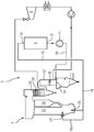
- FIG. 1 shows a steam power plant 2 with a steam generating unit 4 and a thermal energy store 6, which is designed as a rock store.
- the steam power plant 2 furthermore comprises a steam turbine 8, which is driven by means of steam from the steam generation unit 4.
- the steam power plant 2 shown is a converted steam power plant, which originally comprised the steam generating unit 4 and the steam turbine 8 and was subsequently supplemented by the rock storage facility 6 by integrating it into a closed air circuit.
- the fluidized bed boiler 22 is operated completely free of fuel. The entire thermal energy required is provided by the hot air flow. To make this possible, a higher air throughput than in the original, fossil-fired operation of the fluidized bed boiler 2 is required, in particular by a factor of 2 higher. This is achieved through structural measures to enlarge the air inlet 20, through the formation of new air inlets (for example by converting the original fuel inlet 24) and / or by increasing the pressure in the Hot air duct 18.
- the fluidized bed material is adapted to the new flow conditions in order to continue to ensure optimal heat transfer.
- a particle filter 30, shown symbolically here can be installed in the cyclone 26 of the fluidized bed boiler 22, e.g. in a downstream superheater 28 or a flue gas duct 32 with heat exchange surfaces, in order to intercept particles that are carried out of the fluidized bed by the air and are in the closed air- Circuit could reach the fan and damage it.
- a further modification in the area of the flue gas flue 32 ensures that a regenerative air preheater of the boiler 22 that is no longer required is shut off with a plate 34, for example, and is no longer flowed through.
- the air leaves the steam generation unit 4 via an air discharge line 36 in which the fan 14 is integrated and which opens into the air inlet 12 of the energy store 6.
- the air temperature is between 250 ° C and 400 ° C.
- the steam generated in the boiler 22 is fed to the steam turbine 8 and expanded.
- the mechanical / electrical energy released in the process can be fed into the network as a withdrawal service from the system.
Landscapes
- Engineering & Computer Science (AREA)
- Chemical & Material Sciences (AREA)
- Combustion & Propulsion (AREA)
- Mechanical Engineering (AREA)
- General Engineering & Computer Science (AREA)
- Physics & Mathematics (AREA)
- Thermal Sciences (AREA)
- Air Supply (AREA)
Abstract
Die Erfindung betrifft ein Dampfkraftwerk (2) umfassend eine Dampferzeugungseinheit (4) und einen thermischen Energiespeicher (6), wobei die Dampferzeugungseinheit (4) einen fossil gefeuerten Kessel (22) mit mindestens einem Heißlufteinlass (20) aufweist. Im Hinblick auf eine möglichst kostengünstige und effiziente Integration des thermischen Energiespeichers (6) in das Dampfkraftwerk (2) wird der Kessel (?22 mit Heißluft aus dem Energiespeicher (6) betrieben. Hierfür weist der Energiespeicher (6) einen Lufteinlass (12) sowie einen Luftauslass (16) auf, wobei an den Luftauslass (16) eine Heißluftleitung (18) angeschlossen ist, die in den mindestens einen Heißlufteinlass (20) des Kessels (22) mündet.The invention relates to a steam power plant (2) comprising a steam generating unit (4) and a thermal energy store (6), the steam generating unit (4) having a fossil-fired boiler (22) with at least one hot air inlet (20). With a view to the most economical and efficient integration of the thermal energy store (6) in the steam power plant (2), the boiler (? 22) is operated with hot air from the energy store (6). For this purpose, the energy store (6) has an air inlet (12) and an air outlet (16), a hot air line (18) being connected to the air outlet (16) which opens into the at least one hot air inlet (20) of the boiler (22).
Description
Die Entwicklungen am Stromerzeugungsmarkt fördern die Einführung von Energiespeichertechnologien. In diesem Zusammenhang wurde z.B. von der Firma Siemens Gamesa ein neuartiger elektro-thermischer Energiespeicher (ETES) entwickelt, bei dem überschüssiger Strom als Wärme in Vulkangestein speichert wird.Developments in the power generation market are promoting the introduction of energy storage technologies. In this context, a new type of electro-thermal energy storage (ETES) was developed by Siemens Gamesa, for example, in which excess electricity is stored as heat in volcanic rock.
Thermische Energiespeicher sind zurzeit in Großkraftwerken kaum kommerziell verfügbar, bzw. werden diese Energiespeicher lediglich als additives System parallel zum bestehenden Kreislauf geplant. Hierbei wird zur Wärmeübertragung der eingespeicherten Wärme in den Wasser-/Dampfkreislauf ein zusätzlicher Abhitzekessel (englisch Heat Recovery Steam Generator, kurz HRSG) installiert. Dieser Abhitzekessel ist mit einem erheblichen finanziellen Mehraufwand verbunden.Thermal energy storage systems are currently hardly commercially available in large power plants, or these energy storage systems are only planned as an additive system parallel to the existing cycle. An additional waste heat boiler (English Heat Recovery Steam Generator, or HRSG for short) is installed to transfer the stored heat into the water / steam cycle. This waste heat boiler is associated with considerable additional financial expense.
Der Erfindung liegt die Aufgabe zugrunde, eine effiziente und möglichst kostengünstige Integration eines thermischen Energiespeichers in ein Dampfkraftwerk, insbesondere in ein bestehendes Dampfkraftwerk, zu ermöglichen.The invention is based on the object of enabling an efficient and cost-effective integration of a thermal energy store in a steam power plant, in particular in an existing steam power plant.
Diese Aufgabe wird erfindungsgemäß gelöst durch ein Dampfkraftwerk umfassend eine Dampferzeugungseinheit und einen thermischen Energiespeicher, wobei die Dampferzeugungseinheit einen fossil gefeuerten Kessel mit mindestens einem Heißlufteinlass aufweist, wobei der Energiespeicher einen Lufteinlass sowie einen Luftauslass aufweist und wobei an den Luftauslass eine Heißluftleitung angeschlossen ist, die in den mindestens einen Heißlufteinlass des Kessels mündet.According to the invention, this object is achieved by a steam power plant comprising a steam generating unit and a thermal energy store, the steam generating unit having a fossil-fired boiler with at least one hot air inlet, the energy store having an air inlet and an air outlet, and a hot air line being connected to the air outlet, which in the at least one hot air inlet of the boiler opens.
Die Aufgabe wird weiterhin erfindungsgemäß gelöst durch ein Verfahren zum Umbau eines Dampfkraftwerks, indem eine bereits bestehende Dampferzeugungseinheit, welche einen fossil gefeuerten Kessel mit mindestens einem Heißluftanlass aufweist, durch einen thermischen Energiespeicher ergänzt wird, wobei der Kessel mit Heißluft aus dem Energiespeicher betrieben wird.The object is also achieved according to the invention by a method for converting a steam power plant by adding an already existing steam generating unit which is a fossil fuel Has boiler with at least one hot air inlet, is supplemented by a thermal energy store, the boiler being operated with hot air from the energy store.
Die in Bezug auf das Dampfkraftwerk weiterhin angeführten Vorteile und bevorzugten Ausgestaltungen sind sinngemäß auf das Verfahren und vice versa zu übertragen.The advantages and preferred configurations further cited in relation to the steam power plant can be transferred analogously to the method and vice versa.
Die Erfindung basiert auf der Überlegung, damit sowohl auf der Kostenseite wie auch auf der Effizienzseite ein Optimum erreicht wird, eine Anbindung des thermischen Energiespeichers an ein bestehendes Dampfkraftwerk vorzuschlagen, wobei die Integration des Energiespeichers derart konzipiert wird, dass dieser auf möglichst viele vorhandene Komponenten im Kraftwerk zurückgreift. Um den Prozess möglichst wirtschaftlich betreiben zu können, müssen die zusätzlichen Investitionskosten auf ein Minimum beschränkt werden. Besonders ist anzustreben, auch den relativ teuren Kessel weiter nutzen zu können. Im Energiespeicher wird dabei mittels Luft als Trägermedium thermische Energie eingespeichert. Beim Ausspeichern bzw. Entladen des Energiespeichers wird die Luft durch den Energiespeicher geführt, wobei die Luft Wärmeenergie aus dem Energiespeicher aufnimmt und diese dann als Heißluft dem fossil gefeuerten Kessel zugeführt wird. Der Heißluftstrom hat dabei eine Temperatur von über 700°C, insbesondere von ca. 800°C. Durch partielles Zumischen der Heißluft kann sukzessive fossiler Brennstoff für den Kesselbetrieb eingespart werden.The invention is based on the consideration, so that an optimum is achieved both on the cost side and on the efficiency side, to propose a connection of the thermal energy store to an existing steam power plant, the integration of the energy store being designed in such a way that it is based on as many existing components as possible in the Power plant falls back. In order to be able to operate the process as economically as possible, the additional investment costs must be kept to a minimum. It is particularly important to be able to continue using the relatively expensive boiler. Thermal energy is stored in the energy store using air as a carrier medium. When the energy storage device is discharged or discharged, the air is passed through the energy storage device, the air absorbing thermal energy from the energy storage device and this is then fed as hot air to the fossil-fueled boiler. The hot air stream has a temperature of over 700 ° C, in particular of approx. 800 ° C. Partial admixture of the hot air can gradually save fossil fuel for the boiler operation.
Bevorzugt ist der Energiespeicher ein Gesteinsspeicher. Ein elektrothermischer Energiespeicher (ETES) basiert auf dem Prinzip einer Art "Riesenfön" durch den ein Heißluftstrom erzeugt wird. Das geschieht mit Hilfe von Heizelementen und einem Gebläse. Das Gebläse ist derart ausgelegt, dass der Druck zum Fördern der Luft entlang des gesamten Heißluftpfades ausreichend ist. Im Ladebetrieb wird überschüssiger Strom dem Stromnetz entnommen und über eine Widerstandsheizung in Wärme umgesetzt. Diese Wärme wird von einem Luftstrom aufgenommen und als Heißluft auf den Steinspeicher geführt. Im kalten Speicher wird die fühlbare Wärme der Luft auf die Gesteinsmenge übertragen. Die abgekühlte Luft wird über ein Gebläse den Heizelementen im Kreislaufbetrieb wieder zugeführt. Dieser Ladevorgang kann solange laufen, bis der Speicher seine finale Ladetemperatur erreicht hat. Alternativ zur elektrothermischen Einspeicherung kann vorzugsweise eine solarthermische Einspeicherung erfolgen, bei der ein Solarturmkraftwerk die Heißluft erzeugt.The energy store is preferably a rock store. An electrothermal energy store (ETES) is based on the principle of a kind of "giant hair dryer" through which a stream of hot air is generated. This is done with the help of heating elements and a fan. The fan is designed in such a way that the pressure is sufficient to convey the air along the entire hot air path. In charging mode, excess electricity is taken from the power grid and converted into heat via resistance heating implemented. This heat is absorbed by an air stream and conducted as hot air to the stone storage tank. In the cold storage tank, the sensible heat in the air is transferred to the amount of rock. The cooled air is fed back to the heating elements in circulation mode via a fan. This charging process can continue until the storage tank has reached its final charging temperature. As an alternative to electrothermal storage, solar thermal storage can preferably take place, in which a solar tower power plant generates the hot air.
Gemäß einer bevorzugten, besonders umweltfreundlichen Ausführungsvariante ist der Energiespeicher für einen brennstoffzufuhrfreien Betrieb ausgelegt, so dass der Kessel ausschließlich mit Heißluft aus dem Energiespeicher betrieben wird. Dies bedeutet, dass im Betrieb kein Befeuerungsprozess stattfindet, sondern die Energie der Heißluft aus dem thermischen Energiespeicher ausreichend ist, um den Energiebedarf für den Betrieb des Kessels abzudecken. In diesem Fall werden nur noch die Wärmeübertragungsflächen des Kessels genutzt.According to a preferred, particularly environmentally friendly embodiment variant, the energy store is designed for operation without fuel supply, so that the boiler is operated exclusively with hot air from the energy store. This means that there is no firing process during operation, but the energy of the hot air from the thermal energy storage is sufficient to cover the energy requirements for operating the boiler. In this case, only the boiler's heat transfer surfaces are used.
Gemäß einer weiteren, bevorzugten Ausführungsvariante ist ein geschlossener Luft-Kreislauf zwischen der Dampferzeugungseinheit und dem Energiespeicher ausgebildet, wobei die Heißluftleitung ein Teil von dem geschlossenen Luft-Kreislauf ist. Auf diese Weise wird die Effizienz des Prozesses erhöht, denn die Luft, welche aus der Dampferzeugungseinheit hinausgeführt wird, eine wesentliche höhere Temperatur als die Umgebungstemperatur aufweist und deren Wärme nicht extern abgegeben wird, sondern im geschlossenen Luftkreislauf genutzt wird.According to a further, preferred embodiment variant, a closed air circuit is formed between the steam generating unit and the energy store, the hot air line being part of the closed air circuit. In this way, the efficiency of the process is increased because the air that is led out of the steam generating unit has a significantly higher temperature than the ambient temperature and its heat is not given off externally, but is used in the closed air circuit.
Gemäß einer bevorzugten Ausgestaltung ist der Kessel ein Wirbelschichtkessel. Brennstoff und das Bettmaterial werden durch die Zugabe eines Fluidisierungsmediums, in diesem Fall die Heißluft, in der Schwebe gehalten. Die zerkleinerten Brennstoffpartikel haben eine große Oberfläche, so dass ein guter Ausbrand erfolgen kann. Ein Wirbelschichtkessel ist für den Einsatz im oben beschriebenen Dampfkraftwerk besonders geeignet, da beim Betrieb von diesem Typ Kessel mit Heißluft bei 700°C oder mehr, wie diese aus dem Energiespeicher in den Kessel eingeleitet wird, auf die Befeuerung bzw. auf den Zusatz von Brennstoff verzichtet werden kann.According to a preferred embodiment, the boiler is a fluidized bed boiler. The fuel and the bed material are kept in suspension by the addition of a fluidization medium, in this case the hot air. The crushed fuel particles have a large surface so that good burnout can take place. A fluidized bed boiler is particularly suitable for use in the steam power plant described above suitable, since when operating this type of boiler with hot air at 700 ° C or more, as it is introduced into the boiler from the energy storage device, there is no need for firing or the addition of fuel.
Im Hinblick auf einen störungsfreien Betrieb mit Heißluft im geschlossenen Luftkreislauf ist dem Wirbelschichtkessel innerhalb der Dampferzeugungseinheit ein Partikelfilter nachgeschaltet. Dieser dient dazu Partikel abzufangen, die von der Luft aus dem Wirbelbett mitgerissen werden und das Gebläse beschädigen könnten, nachdem der Luftstrom den Kessel verlassen hat.In order to ensure trouble-free operation with hot air in a closed air circuit, a particle filter is connected downstream of the fluidized bed boiler within the steam generation unit. This serves to intercept particles that are carried away by the air from the fluidized bed and which could damage the fan after the air flow has left the boiler.
Gemäß einer alternativen Ausgestaltung ist der Kessel ein Wasserrohrkessel unterschiedlichster Bauarten wie z.B. Turmkessel mit Durchlaufdampfererzeugung, Trommelkessel, Kessel mit Rostfeuerung usw..According to an alternative embodiment, the boiler is a water tube boiler of the most varied of designs, such as tower boilers with continuous steam generation, drum boilers, boilers with grate firing, etc.
Im Falle, dass der Kessel, der ursprünglich als fossil gefeuerten Kessel ausgelegt war, nun durch den Einsatz des thermischen Energiespeichers ohne Brennstoff betrieben wird, ist vorzugsweise ein Brennstoffeinlass des Kessels mit der Heißluftleitung verbunden. Auf diese Weise kann mehr Luft in den Kessel einströmen, so dass insgesamt eine höhere Luftmenge im Kessel vorhanden ist, welche eine Aufrechterhaltung der hohen Temperatur und somit störungsfreien Betrieb des Kessels ermöglicht.In the event that the boiler, which was originally designed as a fossil-fired boiler, is now operated without fuel through the use of the thermal energy store, a fuel inlet of the boiler is preferably connected to the hot air line. In this way, more air can flow into the boiler, so that overall there is a higher amount of air in the boiler, which enables the high temperature to be maintained and thus trouble-free operation of the boiler.
Vorteilhafterweise wird beim umgebauten Dampfkraftwerk eine höhere Menge an Heißluft in den Kessel zugeführt wird, insbesondere eine um Faktor 2 erhöhte Menge an Heißluft. Dies ist insbesondere dann erforderlich, wenn der Kessel ohne Befeuerungsvorgang betrieben wird, sondern die thermische Energie lediglich über die Heißluft aus dem Energiespeicher zur Verfügung gestellt wird. In diesem Fall werden am Kessel zweckdienlicherweise zusätzliche Heißlufteinlässe angebracht, durch welche die erhöhte Menge an Heißluft in den Kessel befördert wird.In the converted steam power plant, a higher amount of hot air is advantageously fed into the boiler, in particular an amount of hot air increased by a factor of 2. This is particularly necessary when the boiler is operated without a firing process, but instead the thermal energy is only made available via the hot air from the energy store. In this case, additional hot air inlets are expediently attached to the boiler, through which the increased amount of hot air is conveyed into the boiler.
Ein Ausführungsbeispiel der Erfindung wird anhand einer Zeichnung näher erläutert. Hierin zeigt die einzige Figur ein Dampfkraftwerk 2 mit einer Dampferzeugungseinheit 4 und einem thermischen Energiespeicher 6, der als Gesteinsspeicher ausgestaltet ist. Das Dampfkraftwerk 2 umfasst weiterhin eine Dampfturbine 8, die mittels Dampf aus der Dampferzeugungseinheit 4 angetrieben wird.An embodiment of the invention is explained in more detail with reference to a drawing. The single FIGURE shows a
Das gezeigte Dampfkraftwerk 2 ist ein umgebautes Dampfkraftwerk, welches ursprünglich die Dampferzeugungseinheit 4 und die Dampfturbine 8 umfasste und nachträglich durch den Gesteinsspeicher 6 ergänzt wurde, indem dieser in einen geschlossenen Luftkreislauf integriert wurde.The
Bei der Entladung des Gesteinsspeichers 6 wird durch einen Lufteinlass 12 Luft ins Innere des Gesteinsspeichers 6 durch ein Gebläse eingepumpt, welche die im Gestein gespeicherte Wärme aufnimmt und als Heißluft durch einen Luftauslass 16 hinausströmt. Die Heißluft, die eine Temperatur von über 700°C beträgt, strömt einer Heißluftleitung 18 entlang und wird anschließend über einen Heißlufteinlass 20 einem Kessel 22, hier einem Wirbelschichtkessel mit einem Zyklon 26 zugeführt. Ein Teil der Heißluft in der Heißluftleitung 18 wird abgezapft, was durch gestrichelte Linie 18a angedeutet ist, und wird über einen Brennstoffeinlass 24 in den Wirbelschichtkessel 22 eingeleitet.When the
Der Wirbelschichtkessel 22 wird dabei vollständig brennstoffzufuhrfrei betrieben. Die gesamte erforderliche thermische Energie wird durch den Heißluftstrom bereitgestellt. Um dies zu ermöglichen, ist ein höherer Luftdurchsatz als beim ursprünglichen, fossil gefeuerten Betrieb des Wirbelschichtkessels 2 erforderlich, insbesondere um Faktor 2 höher. Dies wird erreicht durch bautechnische Maßnahmen zur Vergrößerung des Lufteinlasses 20, durch die Ausbildung von neuen Lufteinlässen (z.B. indem der ursprüngliche Brennstoffeinlass 24 umfunktioniert wird) und/oder durch Erhöhung des Drucks in der Heißluftleitung 18. Das Wirbelbettmaterial wird auf die neuen strömungstechnischen Verhältnisse abgestimmt, um weiterhin eine optimale Wärmeübertragung zu gewährleisten.The fluidized
Darüber hinaus kann ein hier symbolisch gezeigter Partikelfilter 30 dem Zyklon 26 des Wirbelschichtkessels 22, z.B. in einem nachgeschalteten Überhitzer 28 oder einem Rauchgaszug 32 mit Wärmetauschflächen, installiert werden, um Partikel abzufangen, die von der Luft aus dem Wirbelbett hinausgeführt werden und im geschlossenen Luft-Kreislauf das Gebläse erreichen und beschädigen könnten.In addition, a
Eine weitere Modifikation im Bereich des Rauchgaszugs 32 sorgt dafür, dass ein nicht mehr benötigter regenerativer Luftvorwärmer des Kessels 22 z.B. mit einer Platte 34 abgesperrt wird und so nicht mehr durchströmt wird. Die Luft verlässt die Dampferzeugungseinheit 4 über eine Luftabführleitung 36, in der das Gebläse 14 integriert ist und die in den Lufteinlass 12 des Energiespeichers 6 mündet. In der Luftabführleitung 36 beträgt die Lufttemperatur zwischen 250°C und 400°C.A further modification in the area of the
Der im Kessel 22 erzeugte Dampf wird zur Dampfturbine 8 geführt und entspannt. Die dabei freigesetzte mechanische/elektrische Energie kann als Ausspeicherleistung des Systems dem Netz zugeführt werden.The steam generated in the
Die zusätzliche Implementierung eines Abhitzekessels ist im gezeigten Ausführungsbeispiel entbehrlich, wodurch die Umrüstkosten deutlich reduziert werden. Dies führt zu einer signifikant verbesserten Wirtschaftlichkeit des Energiespeichersystems.The additional implementation of a waste heat boiler can be dispensed with in the exemplary embodiment shown, as a result of which the retrofitting costs are significantly reduced. This leads to a significantly improved economic efficiency of the energy storage system.
Claims (13)
wobei der Energiespeicher (6) ein Gesteinsspeicher ist.Steam power plant (2) according to claim 1,
wherein the energy store (6) is a rock store.
wobei der Kessel (22) für einen brennstoffzufuhrfreien Betrieb ausgelegt ist.Steam power plant (2) according to claim 1 or 2,
wherein the boiler (22) is designed for fuel-free operation.
wobei dem Wirbelschichtkessel innerhalb der Dampferzeugungseinheit (4) ein Partikelfilter (30) nachgeschaltet ist.Steam power plant (2) according to claim 5,
wherein a particle filter (30) is connected downstream of the fluidized bed boiler within the steam generation unit (4).
wobei im geschlossenen Luftkreislauf ein Gebläse (14) eingebaut ist, welches dem Lufteinlass (12) des thermischen Energiespeichers (6) vorgeschaltet ist.Steam power plant (2) according to one of the preceding claims,
wherein a fan (14) is installed in the closed air circuit, which is connected upstream of the air inlet (12) of the thermal energy store (6).
wobei der Kessel (22) ausschließlich mit Heißluft aus dem Energiespeicher (6) betrieben wird.Method according to claim 10,
wherein the boiler (22) is operated exclusively with hot air from the energy store (6).
wobei beim umgebauten Dampfkraftwerk (2) eine höhere Menge an Heißluft in den Kessel (22) zugeführt wird, insbesondere eine um Faktor 2 erhöhte Menge an Heißluft.Method according to claim 10 or 11,
wherein in the converted steam power plant (2) a higher amount of hot air is fed into the boiler (22), in particular an amount of hot air increased by a factor of 2.
wobei am Kessel (22) zusätzliche Heißlufteinlässe angebracht werden.Method according to one of Claims 10 to 12,
wherein additional hot air inlets are attached to the boiler (22).
Priority Applications (2)
| Application Number | Priority Date | Filing Date | Title |
|---|---|---|---|
| EP20156798.9A EP3865685A1 (en) | 2020-02-12 | 2020-02-12 | Steam power plant and method for converting an existing steam power plant |
| PCT/EP2020/087367 WO2021160329A1 (en) | 2020-02-12 | 2020-12-21 | Steam power plant and method for converting an existing steam power plant |
Applications Claiming Priority (1)
| Application Number | Priority Date | Filing Date | Title |
|---|---|---|---|
| EP20156798.9A EP3865685A1 (en) | 2020-02-12 | 2020-02-12 | Steam power plant and method for converting an existing steam power plant |
Publications (1)
| Publication Number | Publication Date |
|---|---|
| EP3865685A1 true EP3865685A1 (en) | 2021-08-18 |
Family
ID=69571905
Family Applications (1)
| Application Number | Title | Priority Date | Filing Date |
|---|---|---|---|
| EP20156798.9A Withdrawn EP3865685A1 (en) | 2020-02-12 | 2020-02-12 | Steam power plant and method for converting an existing steam power plant |
Country Status (2)
| Country | Link |
|---|---|
| EP (1) | EP3865685A1 (en) |
| WO (1) | WO2021160329A1 (en) |
Citations (3)
| Publication number | Priority date | Publication date | Assignee | Title |
|---|---|---|---|---|
| DE102012213976A1 (en) * | 2012-08-07 | 2014-02-13 | Siemens Aktiengesellschaft | Method for participation of steam turbine of power plant at network services and power ramps, involves extracting portion of steam mass flow from boiler, and releasing steam from external storage to steam turbine process when needed |
| DE102014106300A1 (en) * | 2014-05-06 | 2015-11-12 | Deutsches Zentrum für Luft- und Raumfahrt e.V. | Steam delivery device and method of providing steam |
| DE102016218379A1 (en) * | 2016-09-23 | 2018-03-29 | Deutsches Zentrum für Luft- und Raumfahrt e.V. | Buffer method, buffer device and power plant |
-
2020
- 2020-02-12 EP EP20156798.9A patent/EP3865685A1/en not_active Withdrawn
- 2020-12-21 WO PCT/EP2020/087367 patent/WO2021160329A1/en active Application Filing
Patent Citations (3)
| Publication number | Priority date | Publication date | Assignee | Title |
|---|---|---|---|---|
| DE102012213976A1 (en) * | 2012-08-07 | 2014-02-13 | Siemens Aktiengesellschaft | Method for participation of steam turbine of power plant at network services and power ramps, involves extracting portion of steam mass flow from boiler, and releasing steam from external storage to steam turbine process when needed |
| DE102014106300A1 (en) * | 2014-05-06 | 2015-11-12 | Deutsches Zentrum für Luft- und Raumfahrt e.V. | Steam delivery device and method of providing steam |
| DE102016218379A1 (en) * | 2016-09-23 | 2018-03-29 | Deutsches Zentrum für Luft- und Raumfahrt e.V. | Buffer method, buffer device and power plant |
Also Published As
| Publication number | Publication date |
|---|---|
| WO2021160329A1 (en) | 2021-08-19 |
Similar Documents
| Publication | Publication Date | Title |
|---|---|---|
| EP0558899B1 (en) | System for using the heat of the exhaust gases from a coal-fired boiler | |
| EP0526816B1 (en) | Power plant with gas and steam turbines with solar steam generator | |
| EP1984624B1 (en) | Method and device to increase the energy production in a solar thermal power plant | |
| EP2167794B1 (en) | Device and method for the generation of power heat | |
| DE4335216A1 (en) | Steam power plant for generating electrical energy | |
| DE102013210430B4 (en) | Energy storage device for preheating feedwater | |
| DE102006029524A1 (en) | Power generator / hydrogen extraction combination plant | |
| DE4126036A1 (en) | Gas and steam turbine plant with solar heated system generator - with generator connected to heat exchanger in h.p. steam line from waste heat steam generator | |
| DE102009039055A1 (en) | Method and device for separating CO2 from exhaust gas | |
| EP2412943B1 (en) | Device and method for generating hot gas with integrated heating of a heat distribution medium | |
| CN103615908A (en) | Combined waste heat recycling system for stepping-type flat-burning sintering machine | |
| EP0098481B1 (en) | Method for generating electric power in a combined power plant with fluidised bed combustion | |
| EP0530519B1 (en) | Power plant heated with nuclear and fossil energy | |
| EP1208294B1 (en) | Method and device for increasing the pressure of a gas | |
| EP3865685A1 (en) | Steam power plant and method for converting an existing steam power plant | |
| AT518186B1 (en) | Thermal power plant and method for storing heat | |
| DE4222811C1 (en) | Using heat in flue gas from coal-fired boiler - involves rotating heat transmission unit in which flue gas is cooled and withdrawn heat used for tempering combustion air fed to boiler | |
| DE4300192C2 (en) | Method for operating at least two interlinked waste heat processes and steam generation system for carrying out the method | |
| DE202014101401U1 (en) | Thermal storage device | |
| WO2011045213A1 (en) | Adapting the final preheating temperature of a secondary circuit of a power plant by means of selectively activating different extraction connections of a steam turbine | |
| WO2021013389A1 (en) | Gas turbine comprising thermal energy store, method for operating same, and method for modifying same | |
| EP0212311B1 (en) | Combined cycle power station | |
| DE102019006585A1 (en) | Method and device for improving the control and low-load behavior of steam power plants | |
| DE3101051A1 (en) | "INTERMEDIATE CIRCUIT FOR A PRESSURE FLUID BED" | |
| EP2388445A1 (en) | Heat displacement system in a steam power station and steam power station |
Legal Events
| Date | Code | Title | Description |
|---|---|---|---|
| PUAI | Public reference made under article 153(3) epc to a published international application that has entered the european phase |
Free format text: ORIGINAL CODE: 0009012 |
|
| STAA | Information on the status of an ep patent application or granted ep patent |
Free format text: STATUS: THE APPLICATION HAS BEEN PUBLISHED |
|
| AK | Designated contracting states |
Kind code of ref document: A1 Designated state(s): AL AT BE BG CH CY CZ DE DK EE ES FI FR GB GR HR HU IE IS IT LI LT LU LV MC MK MT NL NO PL PT RO RS SE SI SK SM TR |
|
| STAA | Information on the status of an ep patent application or granted ep patent |
Free format text: STATUS: THE APPLICATION IS DEEMED TO BE WITHDRAWN |
|
| 18D | Application deemed to be withdrawn |
Effective date: 20220219 |