EP3865677A1 - Diagnostic de l'état d'un groupe motopropulseur hybride - Google Patents
Diagnostic de l'état d'un groupe motopropulseur hybride Download PDFInfo
- Publication number
- EP3865677A1 EP3865677A1 EP21156836.5A EP21156836A EP3865677A1 EP 3865677 A1 EP3865677 A1 EP 3865677A1 EP 21156836 A EP21156836 A EP 21156836A EP 3865677 A1 EP3865677 A1 EP 3865677A1
- Authority
- EP
- European Patent Office
- Prior art keywords
- powerplant
- electric motor
- frequency response
- health
- perturbing
- Prior art date
- Legal status (The legal status is an assumption and is not a legal conclusion. Google has not performed a legal analysis and makes no representation as to the accuracy of the status listed.)
- Pending
Links
- 230000036541 health Effects 0.000 title claims abstract description 41
- 238000003745 diagnosis Methods 0.000 title description 6
- 230000004044 response Effects 0.000 claims abstract description 50
- 238000000034 method Methods 0.000 claims abstract description 35
- 230000003094 perturbing effect Effects 0.000 claims abstract description 23
- 239000000446 fuel Substances 0.000 claims abstract description 18
- 230000008859 change Effects 0.000 claims description 8
- 238000001914 filtration Methods 0.000 claims description 3
- 238000010586 diagram Methods 0.000 description 11
- 230000006870 function Effects 0.000 description 9
- 238000004590 computer program Methods 0.000 description 8
- 238000012545 processing Methods 0.000 description 5
- 230000003287 optical effect Effects 0.000 description 3
- 238000007689 inspection Methods 0.000 description 2
- 238000005259 measurement Methods 0.000 description 2
- 239000013307 optical fiber Substances 0.000 description 2
- 230000008569 process Effects 0.000 description 2
- 230000000644 propagated effect Effects 0.000 description 2
- 238000007796 conventional method Methods 0.000 description 1
- 230000002596 correlated effect Effects 0.000 description 1
- 230000003247 decreasing effect Effects 0.000 description 1
- 230000006872 improvement Effects 0.000 description 1
- 238000004519 manufacturing process Methods 0.000 description 1
- 238000012986 modification Methods 0.000 description 1
- 230000004048 modification Effects 0.000 description 1
- 239000004065 semiconductor Substances 0.000 description 1
Images


Classifications
-
- F—MECHANICAL ENGINEERING; LIGHTING; HEATING; WEAPONS; BLASTING
- F01—MACHINES OR ENGINES IN GENERAL; ENGINE PLANTS IN GENERAL; STEAM ENGINES
- F01D—NON-POSITIVE DISPLACEMENT MACHINES OR ENGINES, e.g. STEAM TURBINES
- F01D21/00—Shutting-down of machines or engines, e.g. in emergency; Regulating, controlling, or safety means not otherwise provided for
- F01D21/003—Arrangements for testing or measuring
-
- B—PERFORMING OPERATIONS; TRANSPORTING
- B60—VEHICLES IN GENERAL
- B60W—CONJOINT CONTROL OF VEHICLE SUB-UNITS OF DIFFERENT TYPE OR DIFFERENT FUNCTION; CONTROL SYSTEMS SPECIALLY ADAPTED FOR HYBRID VEHICLES; ROAD VEHICLE DRIVE CONTROL SYSTEMS FOR PURPOSES NOT RELATED TO THE CONTROL OF A PARTICULAR SUB-UNIT
- B60W50/00—Details of control systems for road vehicle drive control not related to the control of a particular sub-unit, e.g. process diagnostic or vehicle driver interfaces
- B60W50/04—Monitoring the functioning of the control system
- B60W50/045—Monitoring control system parameters
-
- B—PERFORMING OPERATIONS; TRANSPORTING
- B64—AIRCRAFT; AVIATION; COSMONAUTICS
- B64D—EQUIPMENT FOR FITTING IN OR TO AIRCRAFT; FLIGHT SUITS; PARACHUTES; ARRANGEMENT OR MOUNTING OF POWER PLANTS OR PROPULSION TRANSMISSIONS IN AIRCRAFT
- B64D27/00—Arrangement or mounting of power plants in aircraft; Aircraft characterised by the type or position of power plants
- B64D27/02—Aircraft characterised by the type or position of power plants
- B64D27/026—Aircraft characterised by the type or position of power plants comprising different types of power plants, e.g. combination of a piston engine and a gas-turbine
-
- B—PERFORMING OPERATIONS; TRANSPORTING
- B64—AIRCRAFT; AVIATION; COSMONAUTICS
- B64D—EQUIPMENT FOR FITTING IN OR TO AIRCRAFT; FLIGHT SUITS; PARACHUTES; ARRANGEMENT OR MOUNTING OF POWER PLANTS OR PROPULSION TRANSMISSIONS IN AIRCRAFT
- B64D27/00—Arrangement or mounting of power plants in aircraft; Aircraft characterised by the type or position of power plants
- B64D27/02—Aircraft characterised by the type or position of power plants
- B64D27/24—Aircraft characterised by the type or position of power plants using steam or spring force
-
- B—PERFORMING OPERATIONS; TRANSPORTING
- B64—AIRCRAFT; AVIATION; COSMONAUTICS
- B64F—GROUND OR AIRCRAFT-CARRIER-DECK INSTALLATIONS SPECIALLY ADAPTED FOR USE IN CONNECTION WITH AIRCRAFT; DESIGNING, MANUFACTURING, ASSEMBLING, CLEANING, MAINTAINING OR REPAIRING AIRCRAFT, NOT OTHERWISE PROVIDED FOR; HANDLING, TRANSPORTING, TESTING OR INSPECTING AIRCRAFT COMPONENTS, NOT OTHERWISE PROVIDED FOR
- B64F5/00—Designing, manufacturing, assembling, cleaning, maintaining or repairing aircraft, not otherwise provided for; Handling, transporting, testing or inspecting aircraft components, not otherwise provided for
- B64F5/60—Testing or inspecting aircraft components or systems
-
- F—MECHANICAL ENGINEERING; LIGHTING; HEATING; WEAPONS; BLASTING
- F01—MACHINES OR ENGINES IN GENERAL; ENGINE PLANTS IN GENERAL; STEAM ENGINES
- F01D—NON-POSITIVE DISPLACEMENT MACHINES OR ENGINES, e.g. STEAM TURBINES
- F01D15/00—Adaptations of machines or engines for special use; Combinations of engines with devices driven thereby
- F01D15/10—Adaptations for driving, or combinations with, electric generators
-
- G—PHYSICS
- G05—CONTROLLING; REGULATING
- G05B—CONTROL OR REGULATING SYSTEMS IN GENERAL; FUNCTIONAL ELEMENTS OF SUCH SYSTEMS; MONITORING OR TESTING ARRANGEMENTS FOR SUCH SYSTEMS OR ELEMENTS
- G05B23/00—Testing or monitoring of control systems or parts thereof
- G05B23/02—Electric testing or monitoring
- G05B23/0205—Electric testing or monitoring by means of a monitoring system capable of detecting and responding to faults
- G05B23/0218—Electric testing or monitoring by means of a monitoring system capable of detecting and responding to faults characterised by the fault detection method dealing with either existing or incipient faults
- G05B23/0256—Electric testing or monitoring by means of a monitoring system capable of detecting and responding to faults characterised by the fault detection method dealing with either existing or incipient faults injecting test signals and analyzing monitored process response, e.g. injecting the test signal while interrupting the normal operation of the monitored system; superimposing the test signal onto a control signal during normal operation of the monitored system
-
- F—MECHANICAL ENGINEERING; LIGHTING; HEATING; WEAPONS; BLASTING
- F05—INDEXING SCHEMES RELATING TO ENGINES OR PUMPS IN VARIOUS SUBCLASSES OF CLASSES F01-F04
- F05D—INDEXING SCHEME FOR ASPECTS RELATING TO NON-POSITIVE-DISPLACEMENT MACHINES OR ENGINES, GAS-TURBINES OR JET-PROPULSION PLANTS
- F05D2220/00—Application
- F05D2220/30—Application in turbines
- F05D2220/32—Application in turbines in gas turbines
- F05D2220/323—Application in turbines in gas turbines for aircraft propulsion, e.g. jet engines
-
- F—MECHANICAL ENGINEERING; LIGHTING; HEATING; WEAPONS; BLASTING
- F05—INDEXING SCHEMES RELATING TO ENGINES OR PUMPS IN VARIOUS SUBCLASSES OF CLASSES F01-F04
- F05D—INDEXING SCHEME FOR ASPECTS RELATING TO NON-POSITIVE-DISPLACEMENT MACHINES OR ENGINES, GAS-TURBINES OR JET-PROPULSION PLANTS
- F05D2220/00—Application
- F05D2220/70—Application in combination with
- F05D2220/76—Application in combination with an electrical generator
-
- F—MECHANICAL ENGINEERING; LIGHTING; HEATING; WEAPONS; BLASTING
- F05—INDEXING SCHEMES RELATING TO ENGINES OR PUMPS IN VARIOUS SUBCLASSES OF CLASSES F01-F04
- F05D—INDEXING SCHEME FOR ASPECTS RELATING TO NON-POSITIVE-DISPLACEMENT MACHINES OR ENGINES, GAS-TURBINES OR JET-PROPULSION PLANTS
- F05D2260/00—Function
- F05D2260/80—Diagnostics
-
- F—MECHANICAL ENGINEERING; LIGHTING; HEATING; WEAPONS; BLASTING
- F05—INDEXING SCHEMES RELATING TO ENGINES OR PUMPS IN VARIOUS SUBCLASSES OF CLASSES F01-F04
- F05D—INDEXING SCHEME FOR ASPECTS RELATING TO NON-POSITIVE-DISPLACEMENT MACHINES OR ENGINES, GAS-TURBINES OR JET-PROPULSION PLANTS
- F05D2260/00—Function
- F05D2260/82—Forecasts
- F05D2260/821—Parameter estimation or prediction
-
- F—MECHANICAL ENGINEERING; LIGHTING; HEATING; WEAPONS; BLASTING
- F05—INDEXING SCHEMES RELATING TO ENGINES OR PUMPS IN VARIOUS SUBCLASSES OF CLASSES F01-F04
- F05D—INDEXING SCHEME FOR ASPECTS RELATING TO NON-POSITIVE-DISPLACEMENT MACHINES OR ENGINES, GAS-TURBINES OR JET-PROPULSION PLANTS
- F05D2270/00—Control
- F05D2270/01—Purpose of the control system
- F05D2270/11—Purpose of the control system to prolong engine life
-
- Y—GENERAL TAGGING OF NEW TECHNOLOGICAL DEVELOPMENTS; GENERAL TAGGING OF CROSS-SECTIONAL TECHNOLOGIES SPANNING OVER SEVERAL SECTIONS OF THE IPC; TECHNICAL SUBJECTS COVERED BY FORMER USPC CROSS-REFERENCE ART COLLECTIONS [XRACs] AND DIGESTS
- Y02—TECHNOLOGIES OR APPLICATIONS FOR MITIGATION OR ADAPTATION AGAINST CLIMATE CHANGE
- Y02T—CLIMATE CHANGE MITIGATION TECHNOLOGIES RELATED TO TRANSPORTATION
- Y02T50/00—Aeronautics or air transport
- Y02T50/60—Efficient propulsion technologies, e.g. for aircraft
Definitions
- This disclosure relates to powerplants, e.g., to hybrid powerplants.
- a hybrid gas turbine engine for example, can be connected with a motor, shaft, gear box, combustor, and blade. Each component has its own inertia, and each connection has a spring coefficient and friction. Traditionally, measuring a whole plant model of a gas turbine engine is practically impossible.
- a method can include perturbing an electric motor of a hybrid powerplant having the electric motor and a fuel powered engine.
- the method can include measuring a frequency response of the powerplant due to the perturbing of the electric motor to determine a health of the powerplant and/or one or more components thereof.
- the method can include comparing an expected frequency response to the measured frequency response to determine a health of the powerplant and/or the one or more components thereof.
- Perturbing the electric motor can include modifying a set input speed value with a varying value.
- the varying value can be a sinusoidal sweep.
- Modifying the set input speed value can include summing the set input speed value with the varying value at a first summing block to output a modified input speed value.
- Perturbing the electric motor can include inputting the modified input speed value into a second summing block to subtract a feedback speed to output an error input to a speed controller.
- the method can include filtering the feedback speed through one or more filter modules.
- Perturbing the electric motor can include using the speed controller to control a speed of the electric motor as a function of the error input, thereby varying speed of the electric motor as a function of the varying value.
- Measuring the frequency response can include measuring an output of the vibrational output of the powerplant.
- comparing an expected frequency response to the measured frequency response can include comparing an expected magnitude of one or both of a resonant frequency or an anti-resonant frequency of the expected frequency response with a magnitude of one or both of a resonant frequency or an anti-resonant frequency of the measured frequency response to determine if there is a shaft stiffness change.
- comparing an expected frequency response to the measured frequency response can include comparing one or more of an expected resonant frequency, an expected anti-resonant frequency, or an expected phase plot of the expected frequency response with a respective measured resonant frequency, measured anti-resonant frequency, and/or a measured phase plot of the measured frequency response to determine if there is an inertial change in the powerplant.
- any other suitable comparison to determine a health characteristic of the powerplant and/or one or more components thereof e.g., a common shaft with the electric motor and the fuel powered engine, a gear box, an accessory, any other device mechanically connected or related to the electric motor
- a health characteristic of the powerplant and/or one or more components thereof e.g., a common shaft with the electric motor and the fuel powered engine, a gear box, an accessory, any other device mechanically connected or related to the electric motor
- the fuel powered engine can be a gas turbine engine. Any other suitable engine is contemplated herein.
- the method can include any other suitable method(s) and/or portions thereof.
- a system for diagnosing a health of a hybrid powerplant can include a health module configured to perturb an electric motor of a hybrid powerplant having the electric motor and a fuel powered engine, and measure a frequency response of the powerplant due to the perturbing of the electric motor to determine a health of the powerplant and/or one or more components thereof.
- the health module can be configured to perform any embodiment of a method, e.g., as disclosed herein (e.g., as described above).
- a hybrid electric powerplant can include an electric motor, a fuel powered engine, and any embodiment of a health module, e.g., as disclosed herein (e.g., as described above).
- the powerplant can include any other suitable components.
- the fuel powered engine can be a gas turbine engine, for example, or any other suitable type of engine.
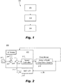
- Fig. 1 an illustrative view of an embodiment of a method in accordance with the disclosure is shown in Fig. 1 and is designated generally by reference character 100.
- FIGs. 2-5 Other embodiments and/or aspects of this disclosure are shown in Figs. 2-5 .
- Certain embodiments described herein can be used to conduct health diagnostics of a hybrid powerplant (e.g., having a turbomachine) and/or or one or more components thereof (e.g., one or more turbomachine components).
- a method 100 can include perturbing (e.g., at block 101) an electric motor of a hybrid powerplant 218 having the electric motor and a fuel powered engine.
- the method 100 can include measuring (e.g., at block 103) a frequency response of the powerplant 218 due to the perturbing (e.g., 101) of the electric motor to determine a health of the powerplant and/or one or more components thereof (e.g., a shaft stiffness, a gear box resistance, etc.).
- the method 100 can include comparing (e.g., at block 105) an expected frequency response 300 to the measured frequency response 400 to determine a health of the powerplant and/or the one or more components thereof Perturbing (e.g., block 101) the electric motor can include modifying a set input speed value 203 with a varying value 205.
- the varying value 205 can be a sinusoidal sweep (e.g., an AC sweep as shown).
- Modifying the set input speed value can include summing the set input speed value 203 with the varying value 205 at a first summing block 207 to output a modified input speed value 209.
- Perturbing e.g., at block 101
- the electric motor can include inputting the modified input speed value into a second summing block 211 to subtract a feedback speed 213 to output an error input 215 to a speed controller 217.
- the method 100 can include filtering the feedback speed through one or more filter modules 219 (e.g., a low pass filter, a moving average filter, or any suitable combination thereof), for example.
- Perturbing (e.g., at block 101) the electric motor can include using the speed controller 217 to control a speed of the electric motor as a function of the error input 215, thereby varying speed of the electric motor as a function of the varying value 205.
- the speed controller 217 can input a torque into a plant model of the powerplant 218.
- the plant model can be configured to receive a torque value from the speed controller 217 and convert the torque value to suitable electrical signals for providing such torque based on one or more plant characteristics, for example.
- Measuring the frequency response can include measuring an output of the vibrational output of the powerplant 218.
- comparing e.g., at block 105) an expected frequency response to the measured frequency response can include comparing an expected magnitude of one or both of a resonant frequency or an anti-resonant frequency of the expected frequency response with a magnitude of one or both of a resonant frequency or an anti-resonant frequency of the measured frequency response (e.g., as shown in Figs. 3 and 4 ) to determine if there is a shaft stiffness change or a turbomachine shaft, for example. It is contemplated that this type of comparison can be used to determine any other suitable condition of the powerplant and/or any suitable components thereof.
- comparing e.g., at block 105) an expected frequency response to the measured frequency response can include comparing one or more of an expected resonant frequency, an expected anti-resonant frequency, or an expected phase plot of the expected frequency response with a respective measured resonant frequency, measured anti-resonant frequency, and/or a measured phase plot of the measured frequency response (e.g., as shown in Figs. 3 and 4 ) to determine if there is an inertial change in the powerplant. It is contemplated that this type of comparison can be used to determine any other suitable condition of the powerplant and/or any suitable components thereof.
- Fig. 5 shows a bode diagram of two different frequency pole at constant speed for measurement of stiffness. By putting AC seep in torque controller, dynamic stiffness can be measured.
- the fuel powered engine can be a gas turbine engine. Any other suitable engine is contemplated herein.
- the method can include any other suitable method(s) and/or portions thereof. Embodiments of a method and/or any portion(s) thereof can implemented by any suitable computerized device having any suitable hardware and/or software modules. One or more embodiments of a method can be stored on a non-transitory computer readable medium to be executable by a suitable computerized device.
- the speed controller can receive an unmodified input speed value and modify it (e.g., with an AC sweep) internally instead of summing the input value ahead of the speed controller. Any other suitable way to perturb the electric motor is contemplated herein.
- a system 200 for diagnosing a health of a hybrid powerplant can include a health module 221 configured to perturb an electric motor of a hybrid powerplant 218 having the electric motor and a fuel powered engine.
- the health module 221 can be configured to measure a frequency response of the powerplant 218 due to the perturbing of the electric motor to determine a health of the powerplant and/or one or more components thereof.
- the health module 221 can be configured to perform any embodiment of a method, e.g., as disclosed herein (e.g., as described above).
- the system 200 can include the speed controller 221, which can have any suitable hardware and/or software module(s). In certain embodiments, e.g., as shown, the speed controller 217 can be included in the health module 221, or vice versa.
- the system 200 can also include the powerplant 218 (e.g., which can receive torque and/or speed commands from the speed controller 217 to control a speed of the electric motor) and/or any other suitable components, e.g., a filter module 219, power electronics for powering the electric motor, and/or one or more vibrational sensors (e.g., connected to the powerplant 218 or any suitable component(s) thereof) for measuring frequency response (e.g., an providing one or more measurement signals to the health module 221).
- the health module 221 can include any suitable components of system 200 (e.g., all processing modules), for example.
- a hybrid electric powerplant 218 can include an electric motor, a fuel powered engine, and any embodiment of a health module, e.g., as disclosed herein (e.g., as described above).
- the powerplant 218 can include any other suitable components.
- the fuel powered engine can be a gas turbine engine (e.g., a turbofan, a turboprop), for example, or any other suitable type of engine.
- Certain embodiments include a speed control loop that includes an AC sweep injected into a speed reference ahead of speed controller, for example.
- the speed controller can receive a speed error and be configured to input more or less power to the electric motor to track the input value such that speed error is moved toward zero.
- a plant model can have information about mechanical system, receive a torque value, and convert it to electrical signals for providing such torque.
- Embodiments can selectively run a health check, e.g., when an aircraft is on the ground.
- a health check When health check is run (on ground), the AC sweep can be input to modify the target speed that the speed controller is tracking, and the response to this changing target can be monitored. For example, if slope or position changes, an inertia change and/or mechanical connection issue can be determined (e.g., and reported to a user). For example, with an inertia increase, a resonant frequency would be decreased. For shaft stiffness, for example, changes in resonant frequency magnitude and anti-resonant frequency magnitude would be seen. Any suitable type of change of response can be correlated to one or more conditions as appreciated by those having ordinary skill in the art in view of this disclosure. In view of this disclosure, one having ordinary skill in the art is enabled without under experimentation to correlate any suitable fault to changes in measured data.
- Embodiments can provide health diagnosis (e.g., on ground) for a hybrid engine using frequency response analysis.
- Embodiments allow health diagnosis for engine mechanical connections, for example, without dedicated sensing or inspection for such diagnosis. The diagnosis can be done quickly with small power when an airplane is on ground, for example.
- Embodiments allow complicated engine connections to be checked by comparing a frequency response result and/or a dynamic stiffness T/ ⁇ (or ⁇ ).
- aspects of the present disclosure may be embodied as a system, method or computer program product. Accordingly, aspects of this disclosure may take the form of an entirely hardware embodiment, an entirely software embodiment (including firmware, resident software, micro-code, etc.), or an embodiment combining software and hardware aspects, all possibilities of which can be referred to herein as a "circuit,” “module,” or “system.”
- a “circuit,” “module,” or “system” can include one or more portions of one or more separate physical hardware and/or software components that can together perform the disclosed function of the "circuit,” “module,” or “system”, or a “circuit,” “module,” or “system” can be a single self-contained unit (e.g., of hardware and/or software).
- aspects of this disclosure may take the form of a computer program product embodied in one or more computer readable medium(s) having computer readable program code embodied thereon.
- the computer readable medium may be a computer readable signal medium or a computer readable storage medium.
- a computer readable storage medium may be, for example, but not limited to, an electronic, magnetic, optical, electromagnetic, infrared, or semiconductor system, apparatus, or device, or any suitable combination of the foregoing.
- a computer readable storage medium may be any tangible medium that can contain, or store a program for use by or in connection with an instruction execution system, apparatus, or device.
- a computer readable signal medium may include a propagated data signal with computer readable program code embodied therein, for example, in baseband or as part of a carrier wave. Such a propagated signal may take any of a variety of forms, including, but not limited to, electro-magnetic, optical, or any suitable combination thereof.
- a computer readable signal medium may be any computer readable medium that is not a computer readable storage medium and that can communicate, propagate, or transport a program for use by or in connection with an instruction execution system, apparatus, or device.
- Program code embodied on a computer readable medium may be transmitted using any appropriate medium, including but not limited to wireless, wireline, optical fiber cable, RF, etc., or any suitable combination of the foregoing.
- Computer program code for carrying out operations for aspects of this disclosure may be written in any combination of one or more programming languages, including an object oriented programming language such as Java, Smalltalk, C++ or the like and conventional procedural programming languages, such as the "C" programming language or similar programming languages.
- the program code may execute entirely on the user's computer, partly on the user's computer, as a stand-alone software package, partly on the user's computer and partly on a remote computer or entirely on the remote computer or server.
- the remote computer may be connected to the user's computer through any type of network, including a local area network (LAN) or a wide area network (WAN), or the connection may be made to an external computer (for example, through the Internet using an Internet Service Provider).
- LAN local area network
- WAN wide area network
- Internet Service Provider for example, AT&T, MCI, Sprint, EarthLink, MSN, GTE, etc.
- These computer program instructions may also be stored in a computer readable medium that can direct a computer, other programmable data processing apparatus, or other devices to function in a particular manner, such that the instructions stored in the computer readable medium produce an article of manufacture including instructions which implement the function/act specified in the flowchart and/or block diagram block or blocks.
- the computer program instructions may also be loaded onto a computer, other programmable data processing apparatus, or other devices to cause a series of operational steps to be performed on the computer, other programmable apparatus or other devices to produce a computer implemented process such that the instructions which execute on the computer or other programmable apparatus provide processes for implementing the functions/acts specified herein.
- any numerical values disclosed herein can be exact values or can be values within a range. Further, any terms of approximation (e.g., “about”, “approximately”, “around”) used in this disclosure can mean the stated value within a range. For example, in certain embodiments, the range can be within (plus or minus) 20%, or within 10%, or within 5%, or within 2%, or within any other suitable percentage or number as appreciated by those having ordinary skill in the art (e.g., for known tolerance limits or error ranges).
- a reference to "A and/or B", when used in conjunction with open-ended language such as “comprising” can refer, in one embodiment, to A only (optionally including elements other than B); in another embodiment, to B only (optionally including elements other than A); in yet another embodiment, to both A and B (optionally including other elements); etc.
Landscapes
- Engineering & Computer Science (AREA)
- Automation & Control Theory (AREA)
- Mechanical Engineering (AREA)
- Aviation & Aerospace Engineering (AREA)
- Transportation (AREA)
- General Engineering & Computer Science (AREA)
- Human Computer Interaction (AREA)
- Manufacturing & Machinery (AREA)
- Physics & Mathematics (AREA)
- General Physics & Mathematics (AREA)
- Testing Of Devices, Machine Parts, Or Other Structures Thereof (AREA)
- Testing Of Engines (AREA)
Applications Claiming Priority (1)
| Application Number | Priority Date | Filing Date | Title |
|---|---|---|---|
| US16/791,513 US11697424B2 (en) | 2020-02-14 | 2020-02-14 | Health diagnosis of hybrid powerplant |
Publications (1)
| Publication Number | Publication Date |
|---|---|
| EP3865677A1 true EP3865677A1 (fr) | 2021-08-18 |
Family
ID=74595153
Family Applications (1)
| Application Number | Title | Priority Date | Filing Date |
|---|---|---|---|
| EP21156836.5A Pending EP3865677A1 (fr) | 2020-02-14 | 2021-02-12 | Diagnostic de l'état d'un groupe motopropulseur hybride |
Country Status (2)
| Country | Link |
|---|---|
| US (1) | US11697424B2 (fr) |
| EP (1) | EP3865677A1 (fr) |
Cited By (1)
| Publication number | Priority date | Publication date | Assignee | Title |
|---|---|---|---|---|
| FR3145553A1 (fr) * | 2023-02-08 | 2024-08-09 | Airbus Helicopters | Procédé de test d’une installation motrice hybride équipant un aéronef, programme d’ordinateur et aéronef associés |
Citations (9)
| Publication number | Priority date | Publication date | Assignee | Title |
|---|---|---|---|---|
| US4287429A (en) * | 1979-07-27 | 1981-09-01 | Bashnin Oleg I | Apparatus for automatically controlling the active power produced by the generator of a hydraulic turbine-generator unit |
| EP1283593A1 (fr) * | 2000-04-20 | 2003-02-12 | Kabushiki Kaisha Yaskawa Denki | Commande de moteur |
| EP1376287A1 (fr) * | 2001-04-04 | 2004-01-02 | Kabushiki Kaisha Yaskawa Denki | Organe de commande de moteur et procede de mesure de caracteristiques d'un mecanisme |
| GB2488805A (en) * | 2011-03-09 | 2012-09-12 | Rolls Royce Plc | Shaft break detection |
| EP3110657A1 (fr) * | 2014-02-28 | 2017-01-04 | BAE Systems Controls Inc. | Filtre de kalman double pour amortissement de torsion d'entraînements de traction électrique |
| US20180224830A1 (en) * | 2017-02-06 | 2018-08-09 | Fanuc Corporation | Servo controller |
| US20180224829A1 (en) * | 2017-02-06 | 2018-08-09 | Fanuc Corporation | Servo controller |
| EP3418504A1 (fr) * | 2017-06-22 | 2018-12-26 | General Electric Company | Procédé de surveillance de l'état de santé et moteur à turbine à gaz |
| WO2018235720A1 (fr) * | 2017-06-20 | 2018-12-27 | 株式会社明電舎 | Procédé d'estimation de caractéristique mécanique |
Family Cites Families (4)
| Publication number | Priority date | Publication date | Assignee | Title |
|---|---|---|---|---|
| US9477223B2 (en) | 2011-09-14 | 2016-10-25 | General Electric Company | Condition monitoring system and method |
| CN102840882B (zh) | 2012-09-04 | 2014-12-10 | 中国海洋石油总公司 | 燃气透平发电机组状态监测和故障诊断系统及其使用方法 |
| WO2018023572A1 (fr) | 2016-08-04 | 2018-02-08 | 薄冰 | Procédé d'ouverture d'un logiciel d'après un geste, et système de téléphone mobile |
| US10590796B2 (en) | 2017-10-19 | 2020-03-17 | United Technologies Corporation | Gas turbine engine drive system torsional health monitoring |
-
2020
- 2020-02-14 US US16/791,513 patent/US11697424B2/en active Active
-
2021
- 2021-02-12 EP EP21156836.5A patent/EP3865677A1/fr active Pending
Patent Citations (9)
| Publication number | Priority date | Publication date | Assignee | Title |
|---|---|---|---|---|
| US4287429A (en) * | 1979-07-27 | 1981-09-01 | Bashnin Oleg I | Apparatus for automatically controlling the active power produced by the generator of a hydraulic turbine-generator unit |
| EP1283593A1 (fr) * | 2000-04-20 | 2003-02-12 | Kabushiki Kaisha Yaskawa Denki | Commande de moteur |
| EP1376287A1 (fr) * | 2001-04-04 | 2004-01-02 | Kabushiki Kaisha Yaskawa Denki | Organe de commande de moteur et procede de mesure de caracteristiques d'un mecanisme |
| GB2488805A (en) * | 2011-03-09 | 2012-09-12 | Rolls Royce Plc | Shaft break detection |
| EP3110657A1 (fr) * | 2014-02-28 | 2017-01-04 | BAE Systems Controls Inc. | Filtre de kalman double pour amortissement de torsion d'entraînements de traction électrique |
| US20180224830A1 (en) * | 2017-02-06 | 2018-08-09 | Fanuc Corporation | Servo controller |
| US20180224829A1 (en) * | 2017-02-06 | 2018-08-09 | Fanuc Corporation | Servo controller |
| WO2018235720A1 (fr) * | 2017-06-20 | 2018-12-27 | 株式会社明電舎 | Procédé d'estimation de caractéristique mécanique |
| EP3418504A1 (fr) * | 2017-06-22 | 2018-12-26 | General Electric Company | Procédé de surveillance de l'état de santé et moteur à turbine à gaz |
Non-Patent Citations (1)
| Title |
|---|
| XIAOMO JIANG: "Recent Development in Structural Damage Diagnosis and Prognosis", RECENT PATENTS ON ENGINEERING 2010, 1 June 2010 (2010-06-01), pages 102 - 121, XP055054941, Retrieved from the Internet <URL:http://docstore.ingenta.com/cgi-bin/ds_deliver/1/u/d/ISIS/73100706.1/ben/eng/2010/00000004/00000002/art00004/A0729BB053E3C6431362072794E4CCE1EF5050F6AB.pdf?link=http://www.ingentaconnect.com/error/delivery&format=pdf> [retrieved on 20130228], DOI: 10.2174/187221210791233434 * |
Cited By (2)
| Publication number | Priority date | Publication date | Assignee | Title |
|---|---|---|---|---|
| FR3145553A1 (fr) * | 2023-02-08 | 2024-08-09 | Airbus Helicopters | Procédé de test d’une installation motrice hybride équipant un aéronef, programme d’ordinateur et aéronef associés |
| EP4414269A1 (fr) | 2023-02-08 | 2024-08-14 | Airbus Helicopters | Procede de test d'une installation motrice hybride equipant un aeronef, programme d'ordinateur et aeronef associes |
Also Published As
| Publication number | Publication date |
|---|---|
| US20210253117A1 (en) | 2021-08-19 |
| US11697424B2 (en) | 2023-07-11 |
Similar Documents
| Publication | Publication Date | Title |
|---|---|---|
| Nguyen et al. | Model-based diagnosis and RUL estimation of induction machines under interturn fault | |
| EP2665925B1 (fr) | Procédé pour diagnostique le monitorage d'un système de générateur d'éolienne | |
| EP3367198B1 (fr) | Procédure de surveillance et de diagnostic de machines rotatives sur la base d'une analyse de signature de signaux électriques | |
| US7323868B2 (en) | System and method for temperature independent measurement of standoff distance using an eddy current sensor | |
| US10767507B2 (en) | Foreign object debris trending concept and design | |
| US10871409B2 (en) | SMD-coil-based torque-sensor for tangential field measurement | |
| JP2016151909A (ja) | 異常診断方法及び異常診断システム | |
| CN107688554A (zh) | 基于自适应傅里叶分解的频域辨识方法 | |
| US10551818B2 (en) | Fault detection methods and systems | |
| EP3865677A1 (fr) | Diagnostic de l'état d'un groupe motopropulseur hybride | |
| JP4788543B2 (ja) | エンジンベンチシステムのパラメータ推定装置 | |
| CN117906991A (zh) | 旋转机械的机器健康监测 | |
| Bektash et al. | Vibration analysis for anomaly detection in unmanned aircraft | |
| CN107792391B (zh) | 基于fadec控制系统的直升机扭振激励试验方法 | |
| Breikin et al. | Dynamic modelling for condition monitoring of gas turbines: Genetic algorithms approach | |
| Yang et al. | Model-based fault diagnosis for performance degradations of turbofan gas path via optimal robust residuals | |
| US11054340B2 (en) | Parametric trending architecture concept and design | |
| Liu et al. | Permanent magnet synchronous motor winding fault simulation and diagnosis | |
| Muzar et al. | Dynamic characterization of brushless dc motors and propellers for flight applications | |
| Modgil et al. | Advanced vibration diagnostics for engine test cells | |
| JP5440619B2 (ja) | 供試体のパラメータ推定装置と機械共振周波数の検出方法 | |
| EP4312099A1 (fr) | Procédé de formation d'un modèle d'apprentissage par machine pour détecter un ou plusieurs défauts | |
| CN114004094B (zh) | 发动机气路故障诊断专家系统构建方法、系统及设备 | |
| Gazzana et al. | A system for incipient fault detection and fault diagnosis based on MCSA | |
| RU2716172C2 (ru) | Способ диагностики асинхронных двигателей с короткозамкнутым ротором |
Legal Events
| Date | Code | Title | Description |
|---|---|---|---|
| PUAI | Public reference made under article 153(3) epc to a published international application that has entered the european phase |
Free format text: ORIGINAL CODE: 0009012 |
|
| STAA | Information on the status of an ep patent application or granted ep patent |
Free format text: STATUS: THE APPLICATION HAS BEEN PUBLISHED |
|
| AK | Designated contracting states |
Kind code of ref document: A1 Designated state(s): AL AT BE BG CH CY CZ DE DK EE ES FI FR GB GR HR HU IE IS IT LI LT LU LV MC MK MT NL NO PL PT RO RS SE SI SK SM TR |
|
| STAA | Information on the status of an ep patent application or granted ep patent |
Free format text: STATUS: REQUEST FOR EXAMINATION WAS MADE |
|
| 17P | Request for examination filed |
Effective date: 20220217 |
|
| RBV | Designated contracting states (corrected) |
Designated state(s): AL AT BE BG CH CY CZ DE DK EE ES FI FR GB GR HR HU IE IS IT LI LT LU LV MC MK MT NL NO PL PT RO RS SE SI SK SM TR |
|
| STAA | Information on the status of an ep patent application or granted ep patent |
Free format text: STATUS: EXAMINATION IS IN PROGRESS |
|
| 17Q | First examination report despatched |
Effective date: 20230630 |