EP3865356B1 - Electric braking device for vehicle and control method thereby - Google Patents
Electric braking device for vehicle and control method thereby Download PDFInfo
- Publication number
- EP3865356B1 EP3865356B1 EP19870349.8A EP19870349A EP3865356B1 EP 3865356 B1 EP3865356 B1 EP 3865356B1 EP 19870349 A EP19870349 A EP 19870349A EP 3865356 B1 EP3865356 B1 EP 3865356B1
- Authority
- EP
- European Patent Office
- Prior art keywords
- control unit
- power source
- source relay
- circuit
- relay circuit
- Prior art date
- Legal status (The legal status is an assumption and is not a legal conclusion. Google has not performed a legal analysis and makes no representation as to the accuracy of the status listed.)
- Active
Links
Images


Classifications
-
- H—ELECTRICITY
- H02—GENERATION; CONVERSION OR DISTRIBUTION OF ELECTRIC POWER
- H02K—DYNAMO-ELECTRIC MACHINES
- H02K7/00—Arrangements for handling mechanical energy structurally associated with dynamo-electric machines, e.g. structural association with mechanical driving motors or auxiliary dynamo-electric machines
- H02K7/14—Structural association with mechanical loads, e.g. with hand-held machine tools or fans
-
- B—PERFORMING OPERATIONS; TRANSPORTING
- B60—VEHICLES IN GENERAL
- B60T—VEHICLE BRAKE CONTROL SYSTEMS OR PARTS THEREOF; BRAKE CONTROL SYSTEMS OR PARTS THEREOF, IN GENERAL; ARRANGEMENT OF BRAKING ELEMENTS ON VEHICLES IN GENERAL; PORTABLE DEVICES FOR PREVENTING UNWANTED MOVEMENT OF VEHICLES; VEHICLE MODIFICATIONS TO FACILITATE COOLING OF BRAKES
- B60T8/00—Arrangements for adjusting wheel-braking force to meet varying vehicular or ground-surface conditions, e.g. limiting or varying distribution of braking force
- B60T8/32—Arrangements for adjusting wheel-braking force to meet varying vehicular or ground-surface conditions, e.g. limiting or varying distribution of braking force responsive to a speed condition, e.g. acceleration or deceleration
- B60T8/88—Arrangements for adjusting wheel-braking force to meet varying vehicular or ground-surface conditions, e.g. limiting or varying distribution of braking force responsive to a speed condition, e.g. acceleration or deceleration with failure responsive means, i.e. means for detecting and indicating faulty operation of the speed responsive control means
- B60T8/92—Arrangements for adjusting wheel-braking force to meet varying vehicular or ground-surface conditions, e.g. limiting or varying distribution of braking force responsive to a speed condition, e.g. acceleration or deceleration with failure responsive means, i.e. means for detecting and indicating faulty operation of the speed responsive control means automatically taking corrective action
-
- B—PERFORMING OPERATIONS; TRANSPORTING
- B60—VEHICLES IN GENERAL
- B60T—VEHICLE BRAKE CONTROL SYSTEMS OR PARTS THEREOF; BRAKE CONTROL SYSTEMS OR PARTS THEREOF, IN GENERAL; ARRANGEMENT OF BRAKING ELEMENTS ON VEHICLES IN GENERAL; PORTABLE DEVICES FOR PREVENTING UNWANTED MOVEMENT OF VEHICLES; VEHICLE MODIFICATIONS TO FACILITATE COOLING OF BRAKES
- B60T13/00—Transmitting braking action from initiating means to ultimate brake actuator with power assistance or drive; Brake systems incorporating such transmitting means, e.g. air-pressure brake systems
- B60T13/74—Transmitting braking action from initiating means to ultimate brake actuator with power assistance or drive; Brake systems incorporating such transmitting means, e.g. air-pressure brake systems with electrical assistance or drive
-
- B—PERFORMING OPERATIONS; TRANSPORTING
- B60—VEHICLES IN GENERAL
- B60T—VEHICLE BRAKE CONTROL SYSTEMS OR PARTS THEREOF; BRAKE CONTROL SYSTEMS OR PARTS THEREOF, IN GENERAL; ARRANGEMENT OF BRAKING ELEMENTS ON VEHICLES IN GENERAL; PORTABLE DEVICES FOR PREVENTING UNWANTED MOVEMENT OF VEHICLES; VEHICLE MODIFICATIONS TO FACILITATE COOLING OF BRAKES
- B60T17/00—Component parts, details, or accessories of power brake systems not covered by groups B60T8/00, B60T13/00 or B60T15/00, or presenting other characteristic features
- B60T17/18—Safety devices; Monitoring
- B60T17/22—Devices for monitoring or checking brake systems; Signal devices
- B60T17/221—Procedure or apparatus for checking or keeping in a correct functioning condition of brake systems
-
- B—PERFORMING OPERATIONS; TRANSPORTING
- B60—VEHICLES IN GENERAL
- B60T—VEHICLE BRAKE CONTROL SYSTEMS OR PARTS THEREOF; BRAKE CONTROL SYSTEMS OR PARTS THEREOF, IN GENERAL; ARRANGEMENT OF BRAKING ELEMENTS ON VEHICLES IN GENERAL; PORTABLE DEVICES FOR PREVENTING UNWANTED MOVEMENT OF VEHICLES; VEHICLE MODIFICATIONS TO FACILITATE COOLING OF BRAKES
- B60T8/00—Arrangements for adjusting wheel-braking force to meet varying vehicular or ground-surface conditions, e.g. limiting or varying distribution of braking force
- B60T8/32—Arrangements for adjusting wheel-braking force to meet varying vehicular or ground-surface conditions, e.g. limiting or varying distribution of braking force responsive to a speed condition, e.g. acceleration or deceleration
- B60T8/88—Arrangements for adjusting wheel-braking force to meet varying vehicular or ground-surface conditions, e.g. limiting or varying distribution of braking force responsive to a speed condition, e.g. acceleration or deceleration with failure responsive means, i.e. means for detecting and indicating faulty operation of the speed responsive control means
- B60T8/885—Arrangements for adjusting wheel-braking force to meet varying vehicular or ground-surface conditions, e.g. limiting or varying distribution of braking force responsive to a speed condition, e.g. acceleration or deceleration with failure responsive means, i.e. means for detecting and indicating faulty operation of the speed responsive control means using electrical circuitry
-
- H—ELECTRICITY
- H02—GENERATION; CONVERSION OR DISTRIBUTION OF ELECTRIC POWER
- H02K—DYNAMO-ELECTRIC MACHINES
- H02K11/00—Structural association of dynamo-electric machines with electric components or with devices for shielding, monitoring or protection
- H02K11/30—Structural association with control circuits or drive circuits
- H02K11/33—Drive circuits, e.g. power electronics
-
- H—ELECTRICITY
- H02—GENERATION; CONVERSION OR DISTRIBUTION OF ELECTRIC POWER
- H02K—DYNAMO-ELECTRIC MACHINES
- H02K7/00—Arrangements for handling mechanical energy structurally associated with dynamo-electric machines, e.g. structural association with mechanical driving motors or auxiliary dynamo-electric machines
- H02K7/10—Structural association with clutches, brakes, gears, pulleys or mechanical starters
- H02K7/102—Structural association with clutches, brakes, gears, pulleys or mechanical starters with friction brakes
-
- H—ELECTRICITY
- H02—GENERATION; CONVERSION OR DISTRIBUTION OF ELECTRIC POWER
- H02P—CONTROL OR REGULATION OF ELECTRIC MOTORS, ELECTRIC GENERATORS OR DYNAMO-ELECTRIC CONVERTERS; CONTROLLING TRANSFORMERS, REACTORS OR CHOKE COILS
- H02P25/00—Arrangements or methods for the control of AC motors characterised by the kind of AC motor or by structural details
- H02P25/16—Arrangements or methods for the control of AC motors characterised by the kind of AC motor or by structural details characterised by the circuit arrangement or by the kind of wiring
- H02P25/22—Multiple windings; Windings for more than three phases
-
- H—ELECTRICITY
- H02—GENERATION; CONVERSION OR DISTRIBUTION OF ELECTRIC POWER
- H02P—CONTROL OR REGULATION OF ELECTRIC MOTORS, ELECTRIC GENERATORS OR DYNAMO-ELECTRIC CONVERTERS; CONTROLLING TRANSFORMERS, REACTORS OR CHOKE COILS
- H02P27/00—Arrangements or methods for the control of AC motors characterised by the kind of supply voltage
- H02P27/04—Arrangements or methods for the control of AC motors characterised by the kind of supply voltage using variable-frequency supply voltage, e.g. inverter or converter supply voltage
- H02P27/06—Arrangements or methods for the control of AC motors characterised by the kind of supply voltage using variable-frequency supply voltage, e.g. inverter or converter supply voltage using DC to AC converters or inverters
-
- H—ELECTRICITY
- H02—GENERATION; CONVERSION OR DISTRIBUTION OF ELECTRIC POWER
- H02P—CONTROL OR REGULATION OF ELECTRIC MOTORS, ELECTRIC GENERATORS OR DYNAMO-ELECTRIC CONVERTERS; CONTROLLING TRANSFORMERS, REACTORS OR CHOKE COILS
- H02P29/00—Arrangements for regulating or controlling electric motors, appropriate for both AC and DC motors
- H02P29/02—Providing protection against overload without automatic interruption of supply
- H02P29/024—Detecting a fault condition, e.g. short circuit, locked rotor, open circuit or loss of load
-
- B—PERFORMING OPERATIONS; TRANSPORTING
- B60—VEHICLES IN GENERAL
- B60T—VEHICLE BRAKE CONTROL SYSTEMS OR PARTS THEREOF; BRAKE CONTROL SYSTEMS OR PARTS THEREOF, IN GENERAL; ARRANGEMENT OF BRAKING ELEMENTS ON VEHICLES IN GENERAL; PORTABLE DEVICES FOR PREVENTING UNWANTED MOVEMENT OF VEHICLES; VEHICLE MODIFICATIONS TO FACILITATE COOLING OF BRAKES
- B60T2270/00—Further aspects of brake control systems not otherwise provided for
- B60T2270/40—Failsafe aspects of brake control systems
- B60T2270/402—Back-up
-
- B—PERFORMING OPERATIONS; TRANSPORTING
- B60—VEHICLES IN GENERAL
- B60T—VEHICLE BRAKE CONTROL SYSTEMS OR PARTS THEREOF; BRAKE CONTROL SYSTEMS OR PARTS THEREOF, IN GENERAL; ARRANGEMENT OF BRAKING ELEMENTS ON VEHICLES IN GENERAL; PORTABLE DEVICES FOR PREVENTING UNWANTED MOVEMENT OF VEHICLES; VEHICLE MODIFICATIONS TO FACILITATE COOLING OF BRAKES
- B60T2270/00—Further aspects of brake control systems not otherwise provided for
- B60T2270/40—Failsafe aspects of brake control systems
- B60T2270/403—Brake circuit failure
-
- B—PERFORMING OPERATIONS; TRANSPORTING
- B60—VEHICLES IN GENERAL
- B60T—VEHICLE BRAKE CONTROL SYSTEMS OR PARTS THEREOF; BRAKE CONTROL SYSTEMS OR PARTS THEREOF, IN GENERAL; ARRANGEMENT OF BRAKING ELEMENTS ON VEHICLES IN GENERAL; PORTABLE DEVICES FOR PREVENTING UNWANTED MOVEMENT OF VEHICLES; VEHICLE MODIFICATIONS TO FACILITATE COOLING OF BRAKES
- B60T2270/00—Further aspects of brake control systems not otherwise provided for
- B60T2270/40—Failsafe aspects of brake control systems
- B60T2270/406—Test-mode; Self-diagnosis
-
- H—ELECTRICITY
- H02—GENERATION; CONVERSION OR DISTRIBUTION OF ELECTRIC POWER
- H02K—DYNAMO-ELECTRIC MACHINES
- H02K11/00—Structural association of dynamo-electric machines with electric components or with devices for shielding, monitoring or protection
- H02K11/20—Structural association of dynamo-electric machines with electric components or with devices for shielding, monitoring or protection for measuring, monitoring, testing, protecting or switching
- H02K11/21—Devices for sensing speed or position, or actuated thereby
-
- H—ELECTRICITY
- H02—GENERATION; CONVERSION OR DISTRIBUTION OF ELECTRIC POWER
- H02K—DYNAMO-ELECTRIC MACHINES
- H02K11/00—Structural association of dynamo-electric machines with electric components or with devices for shielding, monitoring or protection
- H02K11/20—Structural association of dynamo-electric machines with electric components or with devices for shielding, monitoring or protection for measuring, monitoring, testing, protecting or switching
- H02K11/27—Devices for sensing current, or actuated thereby
-
- H—ELECTRICITY
- H02—GENERATION; CONVERSION OR DISTRIBUTION OF ELECTRIC POWER
- H02K—DYNAMO-ELECTRIC MACHINES
- H02K2211/00—Specific aspects not provided for in the other groups of this subclass relating to measuring or protective devices or electric components
- H02K2211/03—Machines characterised by circuit boards, e.g. pcb
-
- H—ELECTRICITY
- H02—GENERATION; CONVERSION OR DISTRIBUTION OF ELECTRIC POWER
- H02K—DYNAMO-ELECTRIC MACHINES
- H02K2213/00—Specific aspects, not otherwise provided for and not covered by codes H02K2201/00 - H02K2211/00
- H02K2213/06—Machines characterised by the presence of fail safe, back up, redundant or other similar emergency arrangements
-
- H—ELECTRICITY
- H02—GENERATION; CONVERSION OR DISTRIBUTION OF ELECTRIC POWER
- H02K—DYNAMO-ELECTRIC MACHINES
- H02K9/00—Arrangements for cooling or ventilating
- H02K9/22—Arrangements for cooling or ventilating by solid heat conducting material embedded in, or arranged in contact with, the stator or rotor, e.g. heat bridges
- H02K9/227—Heat sinks
Definitions
- the present application relates to a vehicle electric braking device and a method of controlling the same.
- Patent Document 1 discloses a vehicle electric brake device in which two coil windings are arranged in parallel with respect to one motor and even when one side coil winding of two coil windings fails, the motor is driven by the other side normal coil winding.
- Patent Document 2 discloses a device which has a motor with several winding groups which rotates about a rotational axis which extends in axial direction.
- a switching element is served as a line switch for winding groups.
- a control component is provided to perform drive control of the motor.
- Several substrates are provided in the axial direction on one side of the motor, and in which the switching element and the control component are mounted.
- the present application discloses a technique which is for solving the foregoing problem and an object of the present application is to provide a vehicle electric braking device that can safely stop a vehicle even when a failure occurs.
- a vehicle electric braking device disclosed in the present application is a vehicle electric braking device including a wheel brake which is connected to a power source mounted on a vehicle and performs braking operation of a brake mechanism of wheels of the vehicle.
- the wheel brake includes: a motor which has two sets of independent coil windings, a first coil winding and a second coil winding, and drives a braking mechanism of the wheels of the vehicle; a first control unit which is connected to the first coil winding of the motor and controls the motor; and a second control unit which is connected to the second coil winding of the motor and controls the motor. Then, the wheel brake is provided on at least any one of the wheels of the vehicle.
- a method of controlling a vehicle electric braking device includes the steps of: determining the presence or absence of an abnormality in each counterpart central processing unit by a first central processing unit of a first control unit or a second central processing unit of a second control unit; determining the presence or absence of an abnormality in a self central processing unit when no abnormality occurs in the counterpart central processing unit; calculating a normal control amount and outputting a control signal to a first inverter circuit of the first control unit or a second inverter circuit of the second control unit when no abnormality occurs also in the self central processing unit; determining the presence or absence of an abnormality in the self central processing unit when an abnormality occurs in the counterpart central processing unit; calculating a control amount under conditions of abnormality of the counterpart central processing unit and normality of the self central processing unit and outputting a control signal to the first inverter circuit of the first control unit or the second inverter circuit of the second control unit when no abnormality occurs in the self central processing unit; and outputting a control signal that
- a method of controlling a vehicle electric braking device includes the steps of: turning OFF a first power source relay circuit and a second power source relay circuit, turning ON a third power source relay circuit and a fourth power source relay circuit, feeding power from a third power source to a first control unit and a second control unit, and outputting driving indication of turning ON to a first inverter circuit of the first control unit and driving indication of turning ON to a second inverter circuit of the second control unit, when no failure occurs in a wheel brake; turning OFF the first power source relay circuit, the second power source relay circuit, and the third power source relay circuit, keeping the fourth power source relay circuit ON continuously, turning OFF driving indication to the first inverter circuit of the first control unit, and keeping driving indication to the second inverter circuit of the second control unit ON continuously, when a failure occurs in the first inverter circuit of the first control unit; turning OFF the first power source relay circuit, the second power source relay circuit, and the fourth power source relay circuit, keeping the third power source
- a method of controlling a vehicle electric braking device includes the steps of: turning ON a first power source relay circuit and a second power source relay circuit, turning OFF a third power source relay circuit and a fourth power source relay circuit, feeding power from a first power source to a first control unit, feeding power from a second power source to a second control unit, and outputting driving indication of turning ON to a first inverter circuit of the first control unit and driving indication of turning ON to a second inverter circuit of the second control unit, when no failure occurs in a wheel brake; turning OFF the first power source relay circuit, the third power source relay circuit, and the fourth power source relay circuit, keeping the second power source relay circuit ON continuously, turning OFF driving indication to the first inverter circuit of the first control unit, and keeping driving indication to the second inverter circuit of the second control unit ON continuously, when a failure occurs in the first inverter circuit of the first control unit; turning OFF the second power source relay circuit, the third power source relay circuit, and the fourth power source
- a method of controlling a vehicle electric braking device includes the steps of: turning ON a first power source relay circuit, a second power source relay circuit, a third power source relay circuit, and a fourth power source relay circuit, feeding power from a third power source to a first control unit, a second control unit, the third power source relay circuit, and the fourth power source relay circuit, and outputting driving indication of turning ON to a first inverter circuit of the first control unit and driving indication of turning ON to a second inverter circuit of the second control unit, when no failure occurs in a wheel brake; turning OFF the first power source relay circuit and the third power source relay circuit, keeping the second power source relay circuit and the fourth power source relay circuit ON continuously, turning OFF driving indication to the first inverter circuit of the first control unit, and keeping driving indication to the second inverter circuit of the second control unit ON continuously, when a failure occurs in the first inverter circuit of the first control unit; turning OFF the second power source relay circuit and the fourth power source relay circuit, keeping
- a vehicle electric braking device and a method of controlling the same disclosed in the present application, there can be obtained a vehicle electric braking device and a method of controlling the same, which can safely stop a vehicle even when a failure occurs in a component related to the vehicle electric braking device.
- FIG. 1 is a circuit diagram showing a wheel brake in a vehicle electric braking device according to Embodiment 1.
- FIG. 2 is a flow chart for explaining a method of controlling the wheel brake in the vehicle electric braking device according to Embodiment 1.
- FIG. 3 is a circuit diagram showing a state where the wheel brake is connected to a brake mechanism and a battery in the vehicle electric braking device according to Embodiment 1.
- FIG. 4 is a block diagram showing the vehicle electric braking device according to Embodiment 1.
- FIG. 1 is a circuit diagram showing a wheel brake in a vehicle electric braking device according to Embodiment 1.
- FIG. 2 is a flow chart for explaining a method of controlling the wheel brake in the vehicle electric braking device according to Embodiment 1.
- FIG. 3 is a circuit diagram showing a state where the wheel brake is connected to a brake mechanism and a battery in the vehicle electric braking device according to Embodiment 1.
- FIG. 4 is a block diagram showing the vehicle electric braking device according
- FIG. 5 is a block diagram showing other example of the vehicle electric braking device according to Embodiment 1.
- FIG. 6 is a block diagram showing other example of the vehicle electric braking device according to Embodiment 1.
- FIG. 7 is a circuit diagram showing other example of a state where a wheel brake is connected to a brake mechanism and batteries in the vehicle electric braking device according to Embodiment 1.
- FIG. 8 is a block diagram showing other example of the vehicle electric braking device according to Embodiment 1.
- a motor 2 is equipped with two sets of independent three phase coil windings, a first coil winding 2a and a second coil winding 2b, with respect to a single unit rotor (not shown in the drawing).
- a first control unit 1a performs driving control of the first coil winding 2a of the motor 2 and a second control unit 1b performs driving control of the second coil winding 2b of the motor 2, thereby operating a brake actuator.
- the first control unit 1a includes: a first inverter circuit 3a, a first control circuit section 4a on which a first central processing unit (hereinafter, referred to as "first CPU") 10a is mounted, a first power source relay switching element 5a that forms a first power source relay circuit, and the like.
- first CPU central processing unit
- the second control unit 1b includes: a second inverter circuit 3b, a second control circuit section 4b on which a second central processing unit (hereinafter, referred to as "second CPU") 10b is mounted, a second power source relay switching element 5b that forms a second power source relay circuit, and the like.
- second CPU central processing unit
- the power source is fed to the first control circuit section 4a via a first power source circuit 13a and the power source is fed to the second control circuit section 4b via a second power source circuit 13b.
- a load sensor which is mounted in the vicinity of the brake actuator and detects pressing force of the brake actuator
- a speed sensor that detects vehicle running speed, and the like
- a sensor 8 inputted from a sensor 8 to the first control circuit section 4a and the second control circuit section 4b.
- a large number of terminals, 17a, 17b, 17c, which are for connecting to external devices are provided on the first control unit 1a and the second control unit 1b and, specifically, such terminals are arranged by fixing connectors to circuit boards.
- the information from the sensor 8 is transmitted to the first CPU 10a via a first input circuit 12a of the first control circuit section 4a and to the second CPU 10b via a second input circuit 12b of the second control circuit section 4b.
- the first CPU 10a calculates a current value which is for rotating the motor 2 on the basis of the inputted information and outputs a control signal to a first output circuit 11a; and the second CPU 10b calculates a current value which is for rotating the motor 2 on the basis of the inputted information and outputs a control signal to a second output circuit 11b.
- the first output circuit 11a receives an input signal and outputs a control signal that controls the respective switching elements of the first inverter circuit 3a that constitutes an output circuit; and the second output circuit 11b receives an input signal and outputs a control signal that controls the respective switching elements of the second inverter circuit 3b that constitutes an output circuit.
- the first output circuit 11a is arranged in the first control circuit section 4a and the second output circuit 11b is arranged in the second control circuit section 4b; however, the first output circuit 11a may be arranged in the first inverter circuit 3a and the second output circuit 11b may be arranged in the second inverter circuit 3b.
- first inverter circuit 3a and the second inverter circuit 3b have the same circuit configuration with respect to respective phases (U1, V1, W1) of the first coil winding 2a of the motor 2 and respective phases (U2, V2, W2) of the second coil winding 2b of the motor 2 and current is independently supplied to the respective phases of the first coil winding 2a and the respective phases of the second coil winding 2b.
- the first inverter circuit 3a is provided with: first upper arm switching elements (31U1, 31V1, 31W1) and first lower arm switching elements (32U1, 32V1, 32W1), which supply an output current to the three phase first coil winding 2a (U1, V1, W1) of the motor 2; first motor relay switching elements 34U1, 34V1, 34W1 which are connected to or disconnected from wiring with the respective phases U1, V1, W1 of the first coil winding 2a of the motor 2; first shunt resistors 33U1, 33V1, 33W1 for current detection; and first noise suppression capacitors 30U1, 30V1, 30W1.
- the second inverter circuit 3b is provided with: second upper arm switching elements (31U2, 31V2, 31W2) and second lower arm switching elements (32U2, 32V2, 32W2), which supply an output current to the three phase second coil winding 2b (U2, V2, W2) of the motor 2; second motor relay switching elements 34U2, 34V2, 34W2 which are connected to or disconnected from wiring with the respective phases U2, V2, W2 of the second coil winding 2b of the motor 2; second shunt resistors 33U2, 33V2, 33W2 for current detection; and second noise suppression capacitors 30U2, 30V2, 30W2.
- a potential difference across terminals of the first shunt resistors 33U1, 33V1, 33W1 and, for example, a terminal voltage of the first coil winding 2a of the motor 2 are also inputted to the first input circuit 12a; and a potential difference across terminals of the second shunt resistors 33U2, 33V2, 33W2 and, for example, a terminal voltage of the second coil winding 2b of the motor 2 are also inputted to the second input circuit 12b.
- a configuration is made such that these kinds of information are also inputted to the first CPU 10a and the second CPU 10b, a difference from a detected value corresponding to a calculated current value is calculated, and a so-called feedback control is performed, whereby a necessary motor current is supplied to drive the brake actuator.
- a control signal of the first power source relay switching element 5a is also outputted and current supply to the first coil winding 2a of the motor 2 can be interrupted by the first power source relay switching element 5a; and a control signal of the second power source relay switching element 5b is also outputted and current supply to the second coil winding 2b of the motor 2 can be interrupted by the second power source relay switching element 5b.
- the first motor relay switching elements 34U1, 34V1, 34W1 can also independently interrupt current supply to the first coil winding 2a of the motor 2; and the second motor relay switching elements 34U2, 34V2, 34W2 can also independently interrupt current supply to the second coil winding 2b of the motor 2.
- a first filter 6a constituted of a capacitor and a coil is connected to power source terminals (+B, GND) of the battery 9 to suppress noise emission due to pulse width modulation of the first inverter circuit 3a; and a second filter 6b constituted of a capacitor and a coil is connected to the power source terminals (+B, GND) of the battery 9 to suppress noise emission due to pulse width modulation of the second inverter circuit 3b.
- a configuration may be such that the first power source relay switching element 5a is incorporated in the first inverter circuit 3a so as to be coupled to a heat dissipation body of the first inverter circuit 3a and the second power source relay switching element 5b is incorporated in the second inverter circuit 3b so as to be coupled to a heat dissipation body of the second inverter circuit 3b, whereby the heat is dissipated.
- the first CPU 10a is equipped with an abnormality detection means that detects an abnormality of the first inverter circuit 3a, the first coil winding 2a (U1, V1, W1) of the motor 2, and the like from the inputted various kinds of information
- the second CPU 10b is equipped with an abnormality detection means that detects an abnormality of the second inverter circuit 3b, the second coil winding 2b (U2, V2, W2) of the motor 2, and the like from the inputted various kinds of information. Then, when an abnormality is detected, the first power source relay switching element 5a or the second power source relay switching element 5b is turned OFF and the battery 9 is cut OFF according to the abnormality.
- first motor relay switching elements 34U1, 34V1, 34W1 and the second motor relay switching elements 34U2, 34V2, 34W2 are turned OFF and the current supply can be interrupted.
- a configuration is made such that when an abnormality is detected, the first CPU 10a and the second CPU 10b feed power to a notification device 15 such as a lamp via the first driving circuit 16a and the second driving circuit 16b, respectively, thereby activating the notification device 15.
- the motor 2 is a brushless motor in which two sets of three phase coil windings, the first coil winding 2a and the second coil winding 2b, are each star-connected and on which a first rotation sensor 19a and a second rotation sensor 19b which are for detecting the rotation position of the rotor are mounted.
- Two sets of sensors (not shown in the drawing) are mounted on each of the first rotation sensor 19a and the second rotation sensor 19b in order to secure each redundant system; and rotation information of the rotor is transmitted to each of the first input circuit 12a of the first control circuit section 4a and the second input circuit 12b of the second control circuit section 4b.
- the motor 2 may be a delta-connected brushless motor or two bipolar pairs of brushed motors rather than the three-phase star-connected brushless motor.
- specifications of coil winding may be a distributed winding or a concentrated winding. However, it is necessary to configure so that the desired number of rotation of the motor and torque can be outputted even only one set of coil windings or two sets of coil windings.
- the motor 2 that constitutes a wheel brake 50 is connected to a brake mechanism 40 and has a role to brake the vehicle.
- a configuration is made such that material subjected to friction (not shown in the drawing) rotated together with wheels (not shown in the drawing) mounted on the vehicle and friction material (not shown in the drawing) which moves by power of the motor 2 are equipped and vehicle braking force is obtained by pressing the friction material to the material subjected to friction.
- the first control unit 1a and the second control unit 1b which constitute the wheel brake 50 are configured so as to be able to independently drive the motor 2 by independently using input information, calculated values, and detected values.
- a communication line 14 is connected between the first CPU 10a and the second CPU 10b so as to be able to transfer data and information.
- Each of operation states of the counterpart first CPU 10a and the second CPU 10b can be grasped by transferring the information by means of the communication line 14.
- matters in which the first CPU 10a detects an abnormality and turns OFF a predetermined switching element can be transmitted to the second CPU 10b. If an abnormality occurs in the first CPU 10a itself or the second CPU 10b itself, a regular communication signal by a predetermined format cannot be transferred, whereby one side CPU can also grasp the occurrence of an abnormality of the other side CPU.
- Step S1 a random access memory (RAM), a read only memory (ROM), a port, and the like are initialized.
- Step S2 all kinds of information inputted via the first input circuit 12a are acquired and stored. Communication data of a counterpart second CPU 10b is also included in this information.
- Step S3 the presence or absence of abnormality detection in the counterpart second CPU 10b is checked.
- the presence or absence of the counterpart abnormality can be determined by deciphering communication data with the counterpart second CPU 10b.
- Step S4 the presence or absence of an abnormality in a self first CPU 10a is checked in Step S4.
- N an abnormality is not detected (N)
- the process is advanced to Step S5 and a normal control amount 1 in which no abnormality occurs in both of the first CPU 10a and the second CPU 10b is calculated.
- Step S3 when an abnormality occurs (Y : Yes) in the counterpart second CPU 10b, the process is advanced to Step S6 and the presence or absence of an abnormality in the self first CPU 10a is checked in the same way as in Step S4.
- Step S11 when an abnormality occurs (Y) in the self first CPU 10a, the process is advanced to Step S11 and processing at the time of self abnormality is performed.
- Step S7 When there is no abnormality (N) in the self first CPU 10a, the process is advanced to Step S7 and control amounts 2 under a condition of abnormality of the counterpart second CPU 10b and a condition of normality of the self first CPU 10a are calculated. Subsequently, the process is advanced to Step S8.
- Step S4 or Step S6 when it is determined that an abnormality occurs in the first CPU 10a itself, the process is advanced to Step S11 and a control signal is outputted so as to stop output to the first output circuit 11a.
- the control signal may be classified into a plurality of levels on the basis of the occurred abnormality. For example, in the case of a ground short or a voltage short of the coil windings 2a, 2b, or the switching elements of the first inverter circuit 3a and the second inverter circuit 3b, a control signal is outputted so as to turn OFF all the switching elements including the first power source relay switching element 5a.
- Step S11 when an open circuit failure occurs in one of the second upper arm switching elements (31U2, 31V2, 31W2) and the second lower arm switching elements (32U2, 32V2, 32W2) of the second inverter circuit 3b, or in the second motor relay switching elements 34U2, 34V2, 34W2, it is also possible to stop driving of the switching element of only a phase where the abnormality occurs and to output a control command to the other phases as normal. Because of this, in Step S11, a setting can be performed so that a part of control can be processed continuously except for processing at the time of abnormality where all the phases are in a stopped state. Incidentally, when two-phase driving can be performed as described above, calculation processing of the control amount is also necessary and thus it may be more efficient to be processed in Steps S5, S7.
- Step S12 data in an abnormal state is transmitted by means of the communication line 14.
- This data is transmitted, also including an abnormality level, for example, matters that all the switching elements are in an OFF state. Furthermore, in a state where only a certain phase is turned OFF, transmission can be made, also including ratio or the like in which a control amount in this case is compared to that in normal time; however, communication of this kind of abnormality contents can also be processed through Step S9 and Step S10. This allows the counterpart second CPU 10b to grasp even the abnormality contents. Consequently, a control amount of the self first CPU 10a can be corrected and outputted according to the abnormality of the counterpart second CPU 10b.
- Step S5 a description will be given on a method of calculating a control amount in normal time when no abnormality occurs in both of the first control unit 1a and the second control unit 1b.
- Step S5 a current value required according to conditions of required pressing force, vehicle speed, or the like is calculated and this is divided into one half.
- This halved current value is the control amount allocated to one side control unit.
- a current being supplied at present is detected from a potential difference across each of the first shunt resistors 33U1, 33V1, 33W1 and is outputted as a control command value according to the difference between a target value and the detected value.
- Step S7 an abnormality occurs in the counterpart system; thus, a current value required for only the self system needs to be calculated and supplied as the control amount 2.
- a calculation is made so as to supply two-thirds the current value, and a control command value thus calculated is outputted.
- the counterpart system is in a state where the motor cannot be driven at all, all the calculated control amount is controlled so as to output in the self system.
- a control amount for two-phase driving can be calculated in Step S5 or Step S7.
- control amount can be calculated by calculating in almost the same procedure as that in normal time and, finally, by correcting for two-phase driving. Additionally, the process can be executed in the same procedure by changing only a distribution rate in the first CPU 10a and the second CPU 10b, whereby simplification of control logic can be achieved.
- Step S8 a control command is outputted so as to be able to drive the respective switching elements on the basis of the control command value.
- the upper and lower arm switching elements of the first inverter circuit 3a and the second inverter circuit 3b are pulse-width modulated and thus their corresponding control signals are outputted.
- Step S9 the presence or absence of an abnormality is checked.
- an abnormality can be detected by a method in which current flowing to drive each switching element is detected by the first shunt resistors 33U1, 33V1, 33W1 and the second shunt resistors 33U2, 33V2, 33W2, and by monitoring a coil winding terminal voltage of the motor and distinguishing that a predetermined voltage appears according to the driving of the switching elements.
- the first CPU 10a When the first CPU 10a detects this kind of abnormality, the first CPU 10a stores, also including an abnormal state and communicates the abnormal state to the counterpart second CPU 10b via the communication line 14 in Step S10. If there is other necessary information, it is efficient when such kind of information is transmitted being included in this process. For example, the accuracy of calculation of each other's control amount can also be checked by transferring information of the first input circuit 12a and information of the control amount.
- Step S13 the process waits until a predetermined time, for example, 5 msec elapses, and if the predetermined time elapses (Y), the process is returned to Step S2 and the process is advanced by repeating in the same procedure again.
- a predetermined time for example, 5 msec elapses
- the above-described processing operation of the first CPU 10a is also executed by the second CPU 10b in the same way, thereby forming a double redundant system.
- Step S1 a RAM, a ROM, a port, and the like are initialized.
- Step S2 all kinds of information inputted via the second input circuit 12b are acquired and stored. Communication data of a counterpart first CPU 10a is also included in this information.
- Step S3 the presence or absence of abnormality detection in the counterpart first CPU 10a is checked.
- the presence or absence of the counterpart abnormality can be determined by deciphering communication data with the counterpart first CPU 10a.
- Step S4 the presence or absence of an abnormality in a self second CPU 10b is checked in Step S4.
- N the process is advanced to Step S5 and a normal control amount 1 in which no abnormality occurs in both of the first CPU 10a and the second CPU 10b is calculated.
- Step S3 when an abnormality occurs (Y : Yes) in the counterpart first CPU 10a, the process is advanced to Step S6 and the presence or absence of an abnormality in the self second CPU 10b is checked in the same way as in Step S4.
- Step S11 when an abnormality occurs (Y) in the self second CPU 10b, the process is advanced to Step S11 and processing at the time of self abnormality is performed.
- Step S7 When there is no abnormality (N) in the self second CPU 10b, the process is advanced to Step S7 and control amounts 2 under a condition of abnormality of the counterpart first CPU 10a and a condition of normality of the self second CPU 10b are calculated. Subsequently, the process is advanced to Step S8.
- Step S4 or Step S6 when it is determined that an abnormality occurs in the second CPU 10b itself, the process is advanced to Step S11 and a control signal is outputted so as to stop output to the second output circuit 11b.
- the control signal may be classified into a plurality of levels on the basis of the occurred abnormality. For example, in the case of a ground short or a voltage short of the first coil winding 2a and the second coil winding 2b, or the switching elements of the first inverter circuit 3a and the second inverter circuit 3b, a control signal is outputted so as to turn OFF all the switching elements including the second power source relay switching element 5b.
- Step S11 when an open circuit failure occurs in one of the first upper arm switching elements (31U1, 31V1, 31W1) and the first lower arm switching elements (32U1, 32V1, 32W1) of the first inverter circuit 3a, or in the first motor relay switching elements 34U1, 34V1, 34W1, it is also possible to stop driving of the switching element of only a phase where the abnormality occurs and to output a control command to the other phases as normal. Because of this, in Step S11, a setting can be performed so that a part of control can be processed continuously except for processing at the time of abnormality where all the phases are in a stopped state. Incidentally, when two-phase driving can be performed as described above, calculation processing of the control amount is also necessary and thus it may be more efficient to be processed in Steps S5, S7.
- Step S12 data in an abnormal state is transmitted by means of the communication line 14.
- This data is transmitted, also including an abnormality level, for example, matters that all the switching elements are in an OFF state. Furthermore, in a state where only a certain phase is turned OFF, transmission can be made, also including ratio or the like in which a control amount in this case is compared to that in normal time; however, communication of this kind of abnormality contents can also be processed through Step S9 and Step S10. This allows the counterpart first CPU 10a to grasp even the abnormality contents. Consequently, a control amount of the self second CPU 10b can be corrected and outputted according to the abnormality of the counterpart first CPU 10a.
- Step S5 a description will be given on a method of calculating a control amount in normal time when no abnormality occurs in both of the first control unit 1a and the second control unit 1b.
- Step S5 a current value required according to conditions of required pressing force, vehicle speed, or the like is calculated and this is divided into one half.
- This halved current value is the control amount allocated to one side control unit.
- a current being supplied at present is detected from a potential difference across each of the second shunt resistors 33U2, 33V2, 33W2 and is outputted as a control command value according to the difference between a target value and the detected value.
- Step S7 an abnormality occurs in the counterpart system; thus, a current value required for only the self system needs to be calculated and supplied as the control amount 2.
- a calculation is made so as to supply two-thirds the current value, and a control command value thus calculated is outputted.
- the counterpart system is in a state where the motor cannot be driven at all, all the calculated control amount is controlled so as to output in the self system.
- a control amount for two-phase driving can be calculated in Step S5 or Step S7.
- control amount can be calculated by calculating in almost the same procedure as that in normal time and, finally, by correcting for two-phase driving. Additionally, the process can be executed in the same procedure by changing only a distribution rate in the first CPU 10a and the second CPU 10b, whereby simplification of control logic can be achieved.
- Step S8 a control command is outputted so as to be able to drive the respective switching elements on the basis of the control command value.
- the upper and lower arm switching elements of the first inverter circuit 3a and the second inverter circuit 3b are pulse-width modulated and thus their corresponding control signals are outputted.
- Step S9 the presence or absence of an abnormality is checked.
- an abnormality can be detected by a method in which current flowing to drive each switching element is detected by the first shunt resistors 33U1, 33V1, 33W1 and the second shunt resistors 33U2, 33V2, 33W2, and by monitoring a coil winding terminal voltage of the motor and distinguishing that a predetermined voltage appears according to the driving of the switching elements.
- the second CPU 10b When the second CPU 10b detects this kind of abnormality, the second CPU 10b stores, also including an abnormal state and communicates the abnormal state to the counterpart first CPU 10a via the communication line 14 in Step S10. If there is other necessary information, it is efficient when such kind of information is transmitted being included in this process. For example, the accuracy of calculation of each other's control amount can also be checked by transferring information of the second input circuit 12b and information of the control amount.
- Step S13 the process waits until a predetermined time, for example, 5 msec elapses, and if the predetermined time elapses (Y), the process is returned to Step S2 and the process is advanced by repeating in the same procedure again.
- a predetermined time for example, 5 msec elapses
- each control unit is allocated one-half each and performs control of the motor 2; however, when an abnormality occurs in one side control unit, a power source relay connected to its system is turned OFF and a power source relay connected to a normal system is kept ON. Then, even in a worst case, a normal CPU can continue 100% control and does not fall into a situation where driving of a brake actuator becomes difficult.
- Step S10 or Step S12 there can be appended a function that notifies abnormality of not only the self system but also the counterpart system, notification to a driver in the occurrence of abnormality is assured, and the driver can also be informed of which side of the motor 2 is abnormal.
- This notification can be achieved by actuating the notification device 15 in Step S10 or Step S12 on the basis of output at the time of abnormality in Step S9 or Step S11.
- the sharing ratio of the control amount can be theoretically changed in any way; however, the ratio having only two or three stages is advantageous in light of simplification of control specifications, simplification of CPU programs, and measures at the time of abnormality of the CPU itself.
- Step S9 an abnormality detection means of Step S9 is arranged after output Step S8; however, the abnormality detection means may be provided between, for example, Step S2 and Step S3.
- one side control unit becomes abnormal and if a heat sink (not shown in the drawing) is a single unit, the entire heat sink can be used by only one system; thus, heat dissipation properties can be improved. Moreover, heat bias can be eliminated to form even heat distribution by this single unit heat sink (not shown in the drawing).
- various types of sensors are suitably mountable and are not limited to the sensor described in this embodiment.
- the first shunt resistor and the second shunt resistor are non-contact current sensors.
- the connector, the motor relay, the noise suppression capacitor, the filter, and the like are mounted; however, these may not be mounted or may be mounted by changing their configuration and similar effects can be obtained.
- the wheel brake 50 shown in FIG. 3 is a piece of apparatus which brakes at least one of the wheels mounted on the vehicle.
- the vehicle electric braking device in Embodiment 1 of the present application is constituted of the combination of the battery 9, the brake mechanism 40, and the wheel brake 50 and is mounted on the vehicle.
- the wheel brake 50 is constituted of: the motor 2 equipped with two sets of independent three phase coil windings, the first coil winding 2a and the second coil winding 2b, with respect to the single unit rotor (not shown in the drawing); the first control unit 1a which is connected to the first coil winding 2a of the motor 2 and controls the first coil winding 2a of the motor 2; and the second control unit 1b which is connected to the second coil winding 2b of the motor 2 and controls the second coil winding 2b of the motor 2.
- the number of battery 9 serving as the power source is one and the battery 9 is connected to the first control unit 1a and the second control unit 1b; and the motor 2 is connected to the brake mechanism 40.
- the first inverter circuit 3a of the first control unit 1a has three phase circuit configuration with respect to the respective phases (U1, V1, W1) of the first coil winding 2a of the motor 2 and is configured so as to independently supply a current to each phase of the first coil winding 2a.
- the second inverter circuit 3b of the second control unit 1b has three phase circuit configuration with respect to the respective phases (U2, V2, W2) of the second coil winding 2b of the motor 2 and is configured so as to independently supply a current to each phase of the second coil winding 2b.
- FIG. 4 to FIG. 6 Examples of the vehicle electric braking device in Embodiment 1 of the present application will be shown in FIG. 4 to FIG. 6 .
- Reference numeral 60 denotes a vehicle in which four wheels 41a, 41b, 41c, 41d are mounted. Brake mechanisms 40a, 40b, 40c, 40d are mounted on the wheels 41a, 41b, 41c, 41d, respectively. Although details of the brake mechanisms 40a, 40b, 40c, 40d are not shown, the brake mechanism is not a mechanism related to electric braking that is a feature of the present application, but is a conventional hydraulic brake mechanism and drawing and description thereof will be omitted.
- Reference numerals 50a, 50b, 50c, 50d denote wheel brakes and are each connected to the battery 9.
- a configuration is made such that, in the example of FIG. 4 , there is shown a case where the wheel brakes 50a, 50b are connected to two wheels on the front side 41a, 41b, respectively; in the example of FIG. 5 , there is shown a case where the wheel brakes 50c, 50d are connected to two wheels on the rear side 41c, 41d, respectively; and in the example of FIG.
- the wheel brakes 50a, 50b are connected to two wheels on the front side 41a, 41b, respectively, and the wheel brakes 50c, 50d are connected to two wheels on the rear side 41c, 41d, respectively, the wheel brakes 50a, 50b, 50c, 50d being connected to one battery 9.
- the wheel brakes are mounted on a plurality of wheels, whereby the vehicle can be safely stopped, also in the occurrence of a failure.
- a redundant wheel brake of the present application is connected to each of two wheels of four wheels and a wheel brake that is not made redundant, which is constituted of a three phase inverter and a three phase motor, is connected to each of the other two wheels.
- the vehicle can be safely stopped, also in the occurrence of a failure, by combining braking force in four wheels.
- the wheel brake 50 shown in FIG. 7 shows a case where the number of batteries serving as a power source is two and shows a case where a first control unit 1a is connected to a first battery 9a and a second control unit 1b is connected to a second battery 9b.
- a configuration is made such that power is fed from the first battery 9a to the first control unit 1a and power is fed from the second battery 9b to the second control unit 1b.
- the control unit but also the battery serving as the power source are made redundant, whereby safeness in the occurrence of a failure is further improved.
- FIG. 8 shows other example in which the wheel brakes 50a, 50b are mounted on the vehicle 60.
- the power source is the battery, it may be configured such that this is a generator, or a DC/DC converter, or the combination thereof. If the power source is made redundant, similar effects can be obtained.
- the wheel brakes 50a, 50b are connected to two wheels on the front side 41a, 41b, respectively; however, it may be configured such that the wheel brakes 50c, 50d are mounted on two wheels on the rear side 41c, 41d, respectively; or the wheel brakes 50a, 50b are connected to two wheels on the front side 41a, 41b, respectively, and the wheel brakes 50c, 50d are connected to two wheels on the rear side 41c, 41d, respectively.
- the wheel brakes are mounted on a plurality of wheels, whereby the vehicle can be safely stopped, also in the occurrence of a failure.
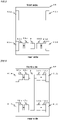
- FIG. 9 is a circuit diagram showing a state where a wheel brake is connected to a brake mechanism and batteries in a vehicle electric braking device according to Embodiment 2.
- FIG. 10 is a block diagram showing the vehicle electric braking device according to Embodiment 2.
- FIG. 11 is a circuit diagram showing the wheel brake in the vehicle electric braking device according to Embodiment 2.
- FIG. 12 is a circuit diagram showing other example of a state where a wheel brake is connected to a brake mechanism and batteries in the vehicle electric braking device according to Embodiment 2.
- FIG. 13 is a block diagram showing other example of the vehicle electric braking device according to Embodiment 2.
- FIG. 11 is the circuit diagram showing an electric relevant part configuration of the wheel brake in the vehicle electric braking device.
- the circuit diagram is configured such that, in the configuration of FIG. 1 described in Embodiment 1, the battery 9 serving as the power source is changed to a battery 9a, a battery 9b, and a battery 9c; a third power source relay switching element 5c, which forms a third power source relay circuit between the battery 9c and the first inverter circuit 3a, is connected in parallel to the first power source relay switching element 5a; and a fourth power source relay switching element 5d, which forms a fourth power source relay circuit between the battery 9c and the second inverter circuit 3b, is connected in parallel to the second power source relay switching element 5b. Since other constituent components are similar to those described in FIG. 1 and the operation as the wheel brake is similar to those described in FIG. 2 , the description thereof will be omitted.
- a wheel brake 50 shown in FIG. 9 shows a case where a first control unit 1a is connected to the first battery 9a and the third battery 9c; and a second control unit 1b is connected to the second battery 9b and the third battery 9c.
- a configuration is made such that power is fed from the first battery 9a or the third battery 9c to the first control unit 1a and power is fed from the second battery 9b or the third battery 9c to the second control unit 1b.
- FIG. 10 shows other example of mounting on a vehicle and the aforementioned effects can be obtained.
- a wheel brake 50 shown in FIG. 12 shows a case where a first control unit 1a is connected to the first battery 9a and the third battery 9c and a second control unit 1b is connected to the second battery 9b and a fourth battery 9d.
- a configuration is made such that power is fed from the first battery 9a or the third battery 9c to the first control unit 1a and power is fed from the second battery 9b or the fourth battery 9d to the second control unit 1b.
- FIG. 13 shows other example of mounting on a vehicle and the aforementioned effects can be obtained.
- the power source is the battery, it may be configured such that this is a generator, or a DC/DC converter, or the combination thereof. If the power source is made redundant, similar effects can be obtained.
- the wheel brakes are connected to two wheels on the front side; however, it may be configured such that the wheel brakes are mounted on two wheels on the rear side; or the wheel brakes are connected to two wheels on the front side and the wheel brakes are connected to two wheels on the rear side.
- the wheel brakes are mounted on a plurality of wheels, whereby the vehicle can be safely stopped, also in the occurrence of a failure.
- a feature of Embodiment 2 is a method of controlling the first power source relay switching element 5a, the second power source relay switching element 5b, the third power source relay switching element 5c, and the fourth power source relay switching element 5d in the case where multiple power sources are connected to the wheel brakes.
- the reason why the multiple power sources are connected to the wheel brakes is to obtain vehicle braking force even when the power source has a failure.
- not only the wheel brakes but also other auxiliary machines are connected to the respective power sources; and accordingly, there is a concern that other auxiliary sources also fail in linkage when the wheel brakes fail.
- FIG. 14 is a control table for explaining a method of controlling a wheel brake in a vehicle electric braking device according to Embodiment 3.
- FIG. 14 shows a method of controlling a first power source relay switching element 5a, a second power source relay switching element 5b, a third power source relay switching element 5c, and a fourth power source relay switching element 5d.
- the first power source relay switching element 5a and the second power source relay switching element 5b are turned OFF, the third power source relay switching element 5c and the fourth power source relay switching element 5d are turned ON, and power is fed from a battery 9c to a first inverter circuit 3a of a first control unit 1a and a second inverter circuit 3b of a second control unit 1b. Then, driving indication of turning ON is outputted to the first inverter circuit 3a of the first control unit 1a and driving indication of turning ON is outputted to the second inverter circuit 3b of the second control unit 1b.
- the operation thereof is performed such that the first power source relay switching element 5a, the second power source relay switching element 5b, and the third power source relay switching element 5c are turned OFF, the fourth power source relay switching element 5d is kept ON continuously, driving indication to the first inverter circuit 3a of the first control unit 1a is turned OFF, and driving indication to the second inverter circuit 3b of the second control unit 1b is kept ON continuously. It is possible to suppress an influence on other auxiliary machine by disconnecting a failed system from the battery and to obtain vehicle braking force continuously by continuing the operation in a normal system.
- the operation thereof is performed such that the first power source relay switching element 5a, the second power source relay switching element 5b, and the fourth power source relay switching element 5d are turned OFF, the third power source relay switching element 5c is kept ON continuously, driving indication to the second inverter circuit 3b of the second control unit 1b is turned OFF, and driving indication to the first inverter circuit 3a of the first control unit 1a is kept ON continuously. It is possible to suppress an influence on other auxiliary machine by disconnecting a failed system from the battery and to obtain vehicle braking force continuously by continuing the operation in a normal system.
- the operation thereof is performed such that the first power source relay switching element 5a, the second power source relay switching element 5b, and the third power source relay switching element 5c are turned OFF, the fourth power source relay switching element 5d is kept ON continuously, driving indication to the first inverter circuit 3a of the first control unit 1a is turned OFF, and driving indication to the second inverter circuit 3b of the second control unit 1b is kept ON continuously. It is possible to suppress an influence on other auxiliary machine by disconnecting a failed system from the battery and to obtain vehicle braking force continuously by continuing the operation in a normal system.
- FIG. 15 is a control table for explaining a method of controlling a wheel brake in a vehicle electric braking device according to Embodiment 4.
- FIG. 15 shows a method of controlling a first power source relay switching element 5a, a second power source relay switching element 5b, a third power source relay switching element 5c, and a fourth power source relay switching element 5d.
- the first power source relay switching element 5a and the second power source relay switching element 5b are turned ON, the third power source relay switching element 5c and the fourth power source relay switching element 5d are turned OFF, power is fed from a first battery 9a to a first inverter circuit 3a of a first control unit 1a, and power is fed from a second battery 9b to a second inverter circuit 3b of a second control unit 1b. Then, driving indication of turning ON is outputted to the first inverter circuit 3a of the first control unit 1a and driving indication of turning ON is outputted to the second inverter circuit 3b of the second control unit 1b.
- the operation thereof is performed such that the first power source relay switching element 5a, the third power source relay switching element 5c, and the fourth power source relay switching element 5d are turned OFF, the second power source relay switching element 5b is kept ON continuously, driving indication to the first inverter circuit 3a of the first control unit 1a is turned OFF, and driving indication to the second inverter circuit 3b of the second control unit 1b is kept ON continuously. It is possible to suppress an influence on other auxiliary machine by disconnecting a failed system from the battery and to obtain vehicle braking force continuously by continuing the operation in a normal system.
- the operation thereof is performed such that the second power source relay switching element 5b, the third power source relay switching element 5c, and the fourth power source relay switching element 5d are turned OFF, the first power source relay switching element 5a is kept ON continuously, driving indication to the second inverter circuit 3b of the second control unit 1b is turned OFF, and driving indication to the first inverter circuit 3a of the first control unit 1a is kept ON continuously. It is possible to suppress an influence on other auxiliary machine by disconnecting a failed system from the battery and to obtain vehicle braking force continuously by continuing the operation in a normal system.
- the operation thereof is performed such that the first power source relay switching element 5a, the third power source relay switching element 5c, and the fourth power source relay switching element 5d are turned OFF, the second power source relay switching element 5b is kept ON continuously, driving indication to the first inverter circuit 3a of the first control unit 1a is turned OFF, and driving indication to the second inverter circuit 3b of the second control unit 1b is kept ON continuously. It is possible to suppress an influence on other auxiliary machine by disconnecting a failed system from the battery and to obtain vehicle braking force continuously by continuing the operation in a normal system.
- FIG. 16 is a control table for explaining a method of controlling a wheel brake in a vehicle electric braking device according to Embodiment 5.
- FIG. 16 shows a method of controlling a first power source relay switching element 5a, a second power source relay switching element 5b, a third power source relay switching element 5c, and a fourth power source relay switching element 5d.
- the operation thereof is performed such that the first power source relay switching element 5a and the third power source relay switching element 5c are turned OFF, the second power source relay switching element 5b and the fourth power source relay switching element 5d are kept ON continuously, driving indication to the first inverter circuit 3a of the first control unit 1a is turned OFF, and driving indication to the second inverter circuit 3b of the second control unit 1b is kept ON continuously. It is possible to suppress an influence on other auxiliary machine by disconnecting a failed system from the battery and to obtain vehicle braking force continuously by continuing the operation in a normal system.
- the operation thereof is performed such that the first power source relay switching element 5a and the third power source relay switching element 5c are turned OFF, the second power source relay switching element 5b and the fourth power source relay switching element 5d are kept ON continuously, driving indication to the first inverter circuit 3a of the first control unit 1a is turned OFF, and driving indication to the second inverter circuit 3b of the second control unit 1b is kept ON continuously. It is possible to suppress an influence on other auxiliary machine by disconnecting a failed system from the battery and to obtain vehicle braking force continuously by continuing the operation in a normal system.
- the inverter circuit can be driven by a plurality of batteries; thus, high output power of the motor is achieved and braking force as the vehicle can be enhanced.
- the first CPU 10a and the second CPU 10b are each constituted of a processor 100 and a storage device 101 as shown in FIG. 17 that is an example of hardware.
- a volatile storage device such as a random access memory and a non-volatile auxiliary storage device such as a flash memory
- an auxiliary storage device of a hard disk may be provided instead of the flash memory.
- the processor 100 executes a program such as a flow chart inputted from the storage device 101. In this case, the program such as the flow chart is inputted from auxiliary storage device to the processor 100 via the volatile storage device.
- the processor 100 may output data such as a calculation result to the volatile storage device of the storage device 101 or may store the data in the auxiliary storage device of the volatile storage device.
- the present application is suitable for actualizing a vehicle electric braking device and a method of controlling the same, which can safely stop a vehicle.
Landscapes
- Engineering & Computer Science (AREA)
- Power Engineering (AREA)
- Transportation (AREA)
- Mechanical Engineering (AREA)
- Microelectronics & Electronic Packaging (AREA)
- Electric Propulsion And Braking For Vehicles (AREA)
- Regulating Braking Force (AREA)
- Braking Systems And Boosters (AREA)
- Control Of Ac Motors In General (AREA)
- Valves And Accessory Devices For Braking Systems (AREA)
Description
- The present application relates to a vehicle electric braking device and a method of controlling the same.
- As a substitution means of a hydraulic braking device which has been used hitherto, development of an electric braking device that obtains vehicle braking force by driving a motor has been being advanced. The braking device has an important function of the vehicle and a redundant system is indispensable so as to be able to safely stop the vehicle even when a failure occurs.
- For example,
Patent Document 1 discloses a vehicle electric brake device in which two coil windings are arranged in parallel with respect to one motor and even when one side coil winding of two coil windings fails, the motor is driven by the other side normal coil winding. -
Patent Document 2 discloses a device which has a motor with several winding groups which rotates about a rotational axis which extends in axial direction. A switching element is served as a line switch for winding groups. A control component is provided to perform drive control of the motor. Several substrates are provided in the axial direction on one side of the motor, and in which the switching element and the control component are mounted. -
- Patent Document 1:
JP,3941243,B - Patent Document 2:
US 2017/291635 A1 - In the configuration of the aforementioned
conventional Patent Document 1, even if one side coil winding of one motor fails, the vehicle braking force can be obtained by driving the motor by the other side normal coil winding. - However, a problem exists in that the configuration of the aforementioned
conventional Patent Document 1 can deal with a failure of the coil winding of the motor; however, there exists only one inverter (three phase bridge circuit) which drives the motor and accordingly the vehicle braking force cannot be obtained when the inverter fails. - The present application discloses a technique which is for solving the foregoing problem and an object of the present application is to provide a vehicle electric braking device that can safely stop a vehicle even when a failure occurs.
- A vehicle electric braking device disclosed in the present application is a vehicle electric braking device including a wheel brake which is connected to a power source mounted on a vehicle and performs braking operation of a brake mechanism of wheels of the vehicle. In the vehicle electric braking device, the wheel brake includes: a motor which has two sets of independent coil windings, a first coil winding and a second coil winding, and drives a braking mechanism of the wheels of the vehicle; a first control unit which is connected to the first coil winding of the motor and controls the motor; and a second control unit which is connected to the second coil winding of the motor and controls the motor. Then, the wheel brake is provided on at least any one of the wheels of the vehicle.
- Furthermore, a method of controlling a vehicle electric braking device disclosed in the present application, includes the steps of: determining the presence or absence of an abnormality in each counterpart central processing unit by a first central processing unit of a first control unit or a second central processing unit of a second control unit; determining the presence or absence of an abnormality in a self central processing unit when no abnormality occurs in the counterpart central processing unit; calculating a normal control amount and outputting a control signal to a first inverter circuit of the first control unit or a second inverter circuit of the second control unit when no abnormality occurs also in the self central processing unit; determining the presence or absence of an abnormality in the self central processing unit when an abnormality occurs in the counterpart central processing unit; calculating a control amount under conditions of abnormality of the counterpart central processing unit and normality of the self central processing unit and outputting a control signal to the first inverter circuit of the first control unit or the second inverter circuit of the second control unit when no abnormality occurs in the self central processing unit; and outputting a control signal that turns OFF to the first inverter circuit of the first control unit or the second inverter circuit of the second control unit when an abnormality occurs in the self central processing unit.
- Moreover, a method of controlling a vehicle electric braking device disclosed in the present application, includes the steps of: turning OFF a first power source relay circuit and a second power source relay circuit, turning ON a third power source relay circuit and a fourth power source relay circuit, feeding power from a third power source to a first control unit and a second control unit, and outputting driving indication of turning ON to a first inverter circuit of the first control unit and driving indication of turning ON to a second inverter circuit of the second control unit, when no failure occurs in a wheel brake; turning OFF the first power source relay circuit, the second power source relay circuit, and the third power source relay circuit, keeping the fourth power source relay circuit ON continuously, turning OFF driving indication to the first inverter circuit of the first control unit, and keeping driving indication to the second inverter circuit of the second control unit ON continuously, when a failure occurs in the first inverter circuit of the first control unit; turning OFF the first power source relay circuit, the second power source relay circuit, and the fourth power source relay circuit, keeping the third power source relay circuit ON continuously, turning OFF driving indication to the second inverter circuit of the second control unit, and keeping driving indication to the first inverter circuit of the first control unit ON continuously, when a failure occurs in the second inverter circuit of the second control unit; turning OFF the first power source relay circuit, the second power source relay circuit, and the third power source relay circuit, keeping the fourth power source relay circuit ON continuously, turning OFF driving indication to the first inverter circuit of the first control unit, and keeping driving indication to the second inverter circuit of the second control unit ON continuously, when a failure occurs in a motor on the first inverter circuit side of the first control unit; and turning OFF the first power source relay circuit, the second power source relay circuit, and the fourth power source relay circuit, keeping the third power source relay circuit ON continuously, turning OFF driving indication to the second inverter circuit of the second control unit, and keeping driving indication to the first inverter circuit of the first control unit ON continuously, when a failure occurs in a motor on the second inverter circuit side of the second control unit.
- Additionally, a method of controlling a vehicle electric braking device disclosed in the present application, includes the steps of: turning ON a first power source relay circuit and a second power source relay circuit, turning OFF a third power source relay circuit and a fourth power source relay circuit, feeding power from a first power source to a first control unit, feeding power from a second power source to a second control unit, and outputting driving indication of turning ON to a first inverter circuit of the first control unit and driving indication of turning ON to a second inverter circuit of the second control unit, when no failure occurs in a wheel brake; turning OFF the first power source relay circuit, the third power source relay circuit, and the fourth power source relay circuit, keeping the second power source relay circuit ON continuously, turning OFF driving indication to the first inverter circuit of the first control unit, and keeping driving indication to the second inverter circuit of the second control unit ON continuously, when a failure occurs in the first inverter circuit of the first control unit; turning OFF the second power source relay circuit, the third power source relay circuit, and the fourth power source relay circuit, keeping the first power source relay circuit ON continuously, turning OFF driving indication to the second inverter circuit of the second control unit, and keeping driving indication to the first inverter circuit of the first control unit ON continuously, when a failure occurs in the second inverter circuit of the second control unit; turning OFF the first power source relay circuit, the third power source relay circuit, and the fourth power source relay circuit, keeping the second power source relay circuit ON continuously, turning OFF driving indication to the first inverter circuit of the first control unit, and keeping driving indication to the second inverter circuit of the second control unit ON continuously, when a failure occurs in a motor on the first inverter circuit side of the first control unit; and turning OFF the second power source relay circuit, the third power source relay circuit, and the fourth power source relay circuit, keeping the first power source relay circuit ON continuously, turning OFF driving indication to the second inverter circuit of the second control unit, and keeping driving indication to the first inverter circuit of the first control unit ON continuously, when a failure occurs in a motor on the second inverter circuit side of the second control unit.
- In addition, a method of controlling a vehicle electric braking device disclosed in the present application, includes the steps of: turning ON a first power source relay circuit, a second power source relay circuit, a third power source relay circuit, and a fourth power source relay circuit, feeding power from a third power source to a first control unit, a second control unit, the third power source relay circuit, and the fourth power source relay circuit, and outputting driving indication of turning ON to a first inverter circuit of the first control unit and driving indication of turning ON to a second inverter circuit of the second control unit, when no failure occurs in a wheel brake; turning OFF the first power source relay circuit and the third power source relay circuit, keeping the second power source relay circuit and the fourth power source relay circuit ON continuously, turning OFF driving indication to the first inverter circuit of the first control unit, and keeping driving indication to the second inverter circuit of the second control unit ON continuously, when a failure occurs in the first inverter circuit of the first control unit; turning OFF the second power source relay circuit and the fourth power source relay circuit, keeping the first power source relay circuit and the third power source relay circuit ON continuously, turning OFF driving indication to the second inverter circuit of the second control unit, and keeping driving indication to the first inverter circuit of the first control unit ON continuously, when a failure occurs in the second inverter circuit of the second control unit; turning OFF the first power source relay circuit and the third power source relay circuit, keeping the second power source relay circuit and the fourth power source relay circuit ON continuously, turning OFF driving indication to the first inverter circuit of the first control unit, and keeping driving indication to the second inverter circuit of the second control unit ON continuously, when a failure occurs in a motor on the first inverter circuit side of the first control unit; and turning OFF the second power source relay circuit and the fourth power source relay circuit, keeping the first power source relay circuit and the third power source relay circuit ON continuously, turning OFF driving indication to the second inverter circuit of the second control unit, and keeping driving indication to the first inverter circuit of the first control unit ON continuously, when a failure occurs in a motor on the second inverter circuit side of the second control unit.
- According to a vehicle electric braking device and a method of controlling the same, disclosed in the present application, there can be obtained a vehicle electric braking device and a method of controlling the same, which can safely stop a vehicle even when a failure occurs in a component related to the vehicle electric braking device.
-
-
FIG. 1 is a circuit diagram showing a wheel brake in a vehicle electric braking device according toEmbodiment 1; -
FIG. 2 is a flow chart for explaining a method of controlling the wheel brake in the vehicle electric braking device according toEmbodiment 1; -
FIG. 3 is a circuit diagram showing a state where the wheel brake is connected to a brake mechanism and a battery in the electric braking device according toEmbodiment 1; -
FIG. 4 is a block diagram showing the vehicle electric braking device according toEmbodiment 1; -
FIG. 5 is a block diagram showing other example of the vehicle electric braking device according toEmbodiment 1; -
FIG. 6 is a block diagram showing other example of the vehicle electric braking device according toEmbodiment 1; -
FIG. 7 is a circuit diagram showing other example of a state where a wheel brake is connected to a brake mechanism and batteries in the vehicle electric braking device according toEmbodiment 1; -
FIG. 8 is a block diagram showing other example of the vehicle electric braking device according toEmbodiment 1; -
FIG. 9 is a circuit diagram showing a state where a wheel brake is connected to a brake mechanism and batteries in a vehicle electric braking device according toEmbodiment 2; -
FIG. 10 is a block diagram showing the vehicle electric braking device according toEmbodiment 2; -
FIG. 11 is a circuit diagram showing the wheel brake in the vehicle electric braking device according toEmbodiment 2; -
FIG. 12 is a circuit diagram showing other example of a state where a wheel brake is connected to a brake mechanism and batteries in the vehicle electric braking device according toEmbodiment 2; -
FIG. 13 is a block diagram showing other example of the vehicle electric braking device according toEmbodiment 2; -
FIG. 14 is a control table for explaining a method of controlling a wheel brake in a vehicle electric braking device according toEmbodiment 3; -
FIG. 15 is a control table for explaining a method of controlling a wheel brake in a vehicle electric braking device according toEmbodiment 4; -
FIG. 16 is a control table for explaining a method of controlling a wheel brake in a vehicle electric braking device according toEmbodiment 5; and -
FIG. 17 is a circuit diagram showing hardware of a first CPU and a second CPU in embodiments. MODE FOR CARRYING OUT THE INVENTION - Hereinafter,
Embodiment 1 will be described on the basis ofFIG. 1 to FIG. 8 . Then, in each of the drawings, identical or equivalent members and portions will be described with the same reference numerals (and letters) assigned thereto.FIG. 1 is a circuit diagram showing a wheel brake in a vehicle electric braking device according toEmbodiment 1.FIG. 2 is a flow chart for explaining a method of controlling the wheel brake in the vehicle electric braking device according toEmbodiment 1.FIG. 3 is a circuit diagram showing a state where the wheel brake is connected to a brake mechanism and a battery in the vehicle electric braking device according toEmbodiment 1.FIG. 4 is a block diagram showing the vehicle electric braking device according toEmbodiment 1.FIG. 5 is a block diagram showing other example of the vehicle electric braking device according toEmbodiment 1.FIG. 6 is a block diagram showing other example of the vehicle electric braking device according toEmbodiment 1.FIG. 7 is a circuit diagram showing other example of a state where a wheel brake is connected to a brake mechanism and batteries in the vehicle electric braking device according toEmbodiment 1.FIG. 8 is a block diagram showing other example of the vehicle electric braking device according toEmbodiment 1. - In
FIG. 1 , amotor 2 is equipped with two sets of independent three phase coil windings, a first coil winding 2a and a second coil winding 2b, with respect to a single unit rotor (not shown in the drawing). Afirst control unit 1a performs driving control of thefirst coil winding 2a of themotor 2 and asecond control unit 1b performs driving control of the second coil winding 2b of themotor 2, thereby operating a brake actuator. Thefirst control unit 1a includes: afirst inverter circuit 3a, a firstcontrol circuit section 4a on which a first central processing unit (hereinafter, referred to as "first CPU") 10a is mounted, a first power sourcerelay switching element 5a that forms a first power source relay circuit, and the like. Thesecond control unit 1b includes: asecond inverter circuit 3b, a secondcontrol circuit section 4b on which a second central processing unit (hereinafter, referred to as "second CPU") 10b is mounted, a second power sourcerelay switching element 5b that forms a second power source relay circuit, and the like. - Furthermore, through an
ignition switch 7 from abattery 9 serving as a power source mounted on the vehicle, the power source is fed to the firstcontrol circuit section 4a via a firstpower source circuit 13a and the power source is fed to the secondcontrol circuit section 4b via a secondpower source circuit 13b. - Moreover, information such as a load sensor which is mounted in the vicinity of the brake actuator and detects pressing force of the brake actuator, a speed sensor that detects vehicle running speed, and the like is inputted from a
sensor 8 to the firstcontrol circuit section 4a and the secondcontrol circuit section 4b. Incidentally, a large number of terminals, 17a, 17b, 17c, which are for connecting to external devices are provided on thefirst control unit 1a and thesecond control unit 1b and, specifically, such terminals are arranged by fixing connectors to circuit boards. - The information from the
sensor 8 is transmitted to thefirst CPU 10a via afirst input circuit 12a of the firstcontrol circuit section 4a and to thesecond CPU 10b via asecond input circuit 12b of the secondcontrol circuit section 4b. Thefirst CPU 10a calculates a current value which is for rotating themotor 2 on the basis of the inputted information and outputs a control signal to afirst output circuit 11a; and thesecond CPU 10b calculates a current value which is for rotating themotor 2 on the basis of the inputted information and outputs a control signal to asecond output circuit 11b. Thefirst output circuit 11a receives an input signal and outputs a control signal that controls the respective switching elements of thefirst inverter circuit 3a that constitutes an output circuit; and thesecond output circuit 11b receives an input signal and outputs a control signal that controls the respective switching elements of thesecond inverter circuit 3b that constitutes an output circuit. - Incidentally, since only a small current flows in the
first output circuit 11a and thesecond output circuit 11b, thefirst output circuit 11a is arranged in the firstcontrol circuit section 4a and thesecond output circuit 11b is arranged in the secondcontrol circuit section 4b; however, thefirst output circuit 11a may be arranged in thefirst inverter circuit 3a and thesecond output circuit 11b may be arranged in thesecond inverter circuit 3b. - Furthermore, a configuration is made such that the
first inverter circuit 3a and thesecond inverter circuit 3b have the same circuit configuration with respect to respective phases (U1, V1, W1) of the first coil winding 2a of themotor 2 and respective phases (U2, V2, W2) of the second coil winding 2b of themotor 2 and current is independently supplied to the respective phases of the first coil winding 2a and the respective phases of the second coil winding 2b. - The
first inverter circuit 3a is provided with: first upper arm switching elements (31U1, 31V1, 31W1) and first lower arm switching elements (32U1, 32V1, 32W1), which supply an output current to the three phase first coil winding 2a (U1, V1, W1) of themotor 2; first motor relay switching elements 34U1, 34V1, 34W1 which are connected to or disconnected from wiring with the respective phases U1, V1, W1 of the first coil winding 2a of themotor 2; first shunt resistors 33U1, 33V1, 33W1 for current detection; and first noise suppression capacitors 30U1, 30V1, 30W1. - The
second inverter circuit 3b is provided with: second upper arm switching elements (31U2, 31V2, 31W2) and second lower arm switching elements (32U2, 32V2, 32W2), which supply an output current to the three phase second coil winding 2b (U2, V2, W2) of themotor 2; second motor relay switching elements 34U2, 34V2, 34W2 which are connected to or disconnected from wiring with the respective phases U2, V2, W2 of the second coil winding 2b of themotor 2; second shunt resistors 33U2, 33V2, 33W2 for current detection; and second noise suppression capacitors 30U2, 30V2, 30W2. - Furthermore, a potential difference across terminals of the first shunt resistors 33U1, 33V1, 33W1 and, for example, a terminal voltage of the first coil winding 2a of the
motor 2 are also inputted to thefirst input circuit 12a; and a potential difference across terminals of the second shunt resistors 33U2, 33V2, 33W2 and, for example, a terminal voltage of the second coil winding 2b of themotor 2 are also inputted to thesecond input circuit 12b. A configuration is made such that these kinds of information are also inputted to thefirst CPU 10a and thesecond CPU 10b, a difference from a detected value corresponding to a calculated current value is calculated, and a so-called feedback control is performed, whereby a necessary motor current is supplied to drive the brake actuator. - Incidentally, a control signal of the first power source
relay switching element 5a is also outputted and current supply to the first coil winding 2a of themotor 2 can be interrupted by the first power sourcerelay switching element 5a; and a control signal of the second power sourcerelay switching element 5b is also outputted and current supply to the second coil winding 2b of themotor 2 can be interrupted by the second power sourcerelay switching element 5b. In the same way, the first motor relay switching elements 34U1, 34V1, 34W1 can also independently interrupt current supply to the first coil winding 2a of themotor 2; and the second motor relay switching elements 34U2, 34V2, 34W2 can also independently interrupt current supply to the second coil winding 2b of themotor 2. - Here, a
first filter 6a constituted of a capacitor and a coil is connected to power source terminals (+B, GND) of thebattery 9 to suppress noise emission due to pulse width modulation of thefirst inverter circuit 3a; and asecond filter 6b constituted of a capacitor and a coil is connected to the power source terminals (+B, GND) of thebattery 9 to suppress noise emission due to pulse width modulation of thesecond inverter circuit 3b. Furthermore, since heat is generated by a large current that flows in the first power sourcerelay switching element 5a and the second power sourcerelay switching element 5b, a configuration may be such that the first power sourcerelay switching element 5a is incorporated in thefirst inverter circuit 3a so as to be coupled to a heat dissipation body of thefirst inverter circuit 3a and the second power sourcerelay switching element 5b is incorporated in thesecond inverter circuit 3b so as to be coupled to a heat dissipation body of thesecond inverter circuit 3b, whereby the heat is dissipated. - By the way, the
first CPU 10a is equipped with an abnormality detection means that detects an abnormality of thefirst inverter circuit 3a, the first coil winding 2a (U1, V1, W1) of themotor 2, and the like from the inputted various kinds of information; and thesecond CPU 10b is equipped with an abnormality detection means that detects an abnormality of thesecond inverter circuit 3b, the second coil winding 2b (U2, V2, W2) of themotor 2, and the like from the inputted various kinds of information. Then, when an abnormality is detected, the first power sourcerelay switching element 5a or the second power sourcerelay switching element 5b is turned OFF and thebattery 9 is cut OFF according to the abnormality. Alternatively, only a predetermined phase of the first motor relay switching elements 34U1, 34V1, 34W1 and the second motor relay switching elements 34U2, 34V2, 34W2 is turned OFF and the current supply can be interrupted. Moreover, a configuration is made such that when an abnormality is detected, thefirst CPU 10a and thesecond CPU 10b feed power to anotification device 15 such as a lamp via thefirst driving circuit 16a and thesecond driving circuit 16b, respectively, thereby activating thenotification device 15. - Meanwhile, the
motor 2 is a brushless motor in which two sets of three phase coil windings, the first coil winding 2a and the second coil winding 2b, are each star-connected and on which afirst rotation sensor 19a and asecond rotation sensor 19b which are for detecting the rotation position of the rotor are mounted. Two sets of sensors (not shown in the drawing) are mounted on each of thefirst rotation sensor 19a and thesecond rotation sensor 19b in order to secure each redundant system; and rotation information of the rotor is transmitted to each of thefirst input circuit 12a of the firstcontrol circuit section 4a and thesecond input circuit 12b of the secondcontrol circuit section 4b. - Incidentally, the
motor 2 may be a delta-connected brushless motor or two bipolar pairs of brushed motors rather than the three-phase star-connected brushless motor. Furthermore, specifications of coil winding may be a distributed winding or a concentrated winding. However, it is necessary to configure so that the desired number of rotation of the motor and torque can be outputted even only one set of coil windings or two sets of coil windings. - As an example, as shown in
FIG. 3 , themotor 2 that constitutes awheel brake 50 is connected to abrake mechanism 40 and has a role to brake the vehicle. Specifically, a configuration is made such that material subjected to friction (not shown in the drawing) rotated together with wheels (not shown in the drawing) mounted on the vehicle and friction material (not shown in the drawing) which moves by power of themotor 2 are equipped and vehicle braking force is obtained by pressing the friction material to the material subjected to friction. - As described above, the
first control unit 1a and thesecond control unit 1b which constitute thewheel brake 50 are configured so as to be able to independently drive themotor 2 by independently using input information, calculated values, and detected values. - Furthermore, a
communication line 14 is connected between thefirst CPU 10a and thesecond CPU 10b so as to be able to transfer data and information. Each of operation states of the counterpartfirst CPU 10a and thesecond CPU 10b can be grasped by transferring the information by means of thecommunication line 14. For example, matters in which thefirst CPU 10a detects an abnormality and turns OFF a predetermined switching element can be transmitted to thesecond CPU 10b. If an abnormality occurs in thefirst CPU 10a itself or thesecond CPU 10b itself, a regular communication signal by a predetermined format cannot be transferred, whereby one side CPU can also grasp the occurrence of an abnormality of the other side CPU. - Next, a control method in the above circuit configuration and motor construction will be described. Since control of each circuit is almost processed in accordance with a program of the
first CPU 10a or that of thesecond CPU 10b, a description will be given according to a flow chart shown inFIG. 2 . Incidentally, thefirst CPU 10a and thesecond CPU 10b perform substantially the same process. First, a description will be given on one sidefirst CPU 10a. - First, when the
ignition switch 7 is switched, a current is supplied to thefirst CPU 10a through the firstpower source circuit 13a and the process is started. - In Step S1, a random access memory (RAM), a read only memory (ROM), a port, and the like are initialized. Next, in Step S2, all kinds of information inputted via the
first input circuit 12a are acquired and stored. Communication data of a counterpartsecond CPU 10b is also included in this information. - In Step S3, the presence or absence of abnormality detection in the counterpart
second CPU 10b is checked. The presence or absence of the counterpart abnormality can be determined by deciphering communication data with the counterpartsecond CPU 10b. When no abnormality occurs (N : No) in the counterpartsecond CPU 10b, the presence or absence of an abnormality in a selffirst CPU 10a is checked in Step S4. Here, when an abnormality is not detected (N), the process is advanced to Step S5 and anormal control amount 1 in which no abnormality occurs in both of thefirst CPU 10a and thesecond CPU 10b is calculated. - Meanwhile, in Step S3, when an abnormality occurs (Y : Yes) in the counterpart
second CPU 10b, the process is advanced to Step S6 and the presence or absence of an abnormality in the selffirst CPU 10a is checked in the same way as in Step S4. Here, when an abnormality occurs (Y) in the selffirst CPU 10a, the process is advanced to Step S11 and processing at the time of self abnormality is performed. When there is no abnormality (N) in the selffirst CPU 10a, the process is advanced to Step S7 and control amounts 2 under a condition of abnormality of the counterpartsecond CPU 10b and a condition of normality of the selffirst CPU 10a are calculated. Subsequently, the process is advanced to Step S8. - Next, in Step S4 or Step S6, when it is determined that an abnormality occurs in the
first CPU 10a itself, the process is advanced to Step S11 and a control signal is outputted so as to stop output to thefirst output circuit 11a. Incidentally, the control signal may be classified into a plurality of levels on the basis of the occurred abnormality. For example, in the case of a ground short or a voltage short of thecoil windings first inverter circuit 3a and thesecond inverter circuit 3b, a control signal is outputted so as to turn OFF all the switching elements including the first power sourcerelay switching element 5a. - Furthermore, when an open circuit failure occurs in one of the first upper arm switching elements (31U1, 31V1, 31W1) and the first lower arm switching elements (32U1, 32V1, 32W1) of the
first inverter circuit 3a, or in the first motor relay switching elements 34U1, 34V1, 34W1, it is also possible to stop driving of the switching element of only a phase where the abnormality occurs and to output a control command to the other phases as normal. Alternatively, when an open circuit failure occurs in one of the second upper arm switching elements (31U2, 31V2, 31W2) and the second lower arm switching elements (32U2, 32V2, 32W2) of thesecond inverter circuit 3b, or in the second motor relay switching elements 34U2, 34V2, 34W2, it is also possible to stop driving of the switching element of only a phase where the abnormality occurs and to output a control command to the other phases as normal. Because of this, in Step S11, a setting can be performed so that a part of control can be processed continuously except for processing at the time of abnormality where all the phases are in a stopped state. Incidentally, when two-phase driving can be performed as described above, calculation processing of the control amount is also necessary and thus it may be more efficient to be processed in Steps S5, S7. - Next, in Step S12, data in an abnormal state is transmitted by means of the
communication line 14. This data is transmitted, also including an abnormality level, for example, matters that all the switching elements are in an OFF state. Furthermore, in a state where only a certain phase is turned OFF, transmission can be made, also including ratio or the like in which a control amount in this case is compared to that in normal time; however, communication of this kind of abnormality contents can also be processed through Step S9 and Step S10. This allows the counterpartsecond CPU 10b to grasp even the abnormality contents. Consequently, a control amount of the selffirst CPU 10a can be corrected and outputted according to the abnormality of the counterpartsecond CPU 10b. - Next, in Step S5, a description will be given on a method of calculating a control amount in normal time when no abnormality occurs in both of the
first control unit 1a and thesecond control unit 1b. - In Step S5, a current value required according to conditions of required pressing force, vehicle speed, or the like is calculated and this is divided into one half. This halved current value is the control amount allocated to one side control unit. Moreover, a current being supplied at present is detected from a potential difference across each of the first shunt resistors 33U1, 33V1, 33W1 and is outputted as a control command value according to the difference between a target value and the detected value.
- Meanwhile, in Step S7, an abnormality occurs in the counterpart system; thus, a current value required for only the self system needs to be calculated and supplied as the
control amount 2. Alternatively, if only one-phase is abnormal and two-phase driving is performed in the counterpart system, a calculation is made so as to supply two-thirds the current value, and a control command value thus calculated is outputted. Furthermore, when the counterpart system is in a state where the motor cannot be driven at all, all the calculated control amount is controlled so as to output in the self system. Moreover, when an abnormality occurs in only on phase as previously described, a control amount for two-phase driving can be calculated in Step S5 or Step S7. More specifically, the control amount can be calculated by calculating in almost the same procedure as that in normal time and, finally, by correcting for two-phase driving. Additionally, the process can be executed in the same procedure by changing only a distribution rate in thefirst CPU 10a and thesecond CPU 10b, whereby simplification of control logic can be achieved. - Next, in Step S8, a control command is outputted so as to be able to drive the respective switching elements on the basis of the control command value. The upper and lower arm switching elements of the
first inverter circuit 3a and thesecond inverter circuit 3b are pulse-width modulated and thus their corresponding control signals are outputted. - In Step S9, the presence or absence of an abnormality is checked. Specifically, an abnormality can be detected by a method in which current flowing to drive each switching element is detected by the first shunt resistors 33U1, 33V1, 33W1 and the second shunt resistors 33U2, 33V2, 33W2, and by monitoring a coil winding terminal voltage of the motor and distinguishing that a predetermined voltage appears according to the driving of the switching elements.
- Moreover, when a difference from the detected current value with respect to the target current value does not come close even after a predetermined time elapses, there is a possibility of a leak and thus it can also be determined as an abnormality.
- As described above, voltage and current of each portion are monitored to detect an abnormality, whereby an abnormality can be detected even in only one phase.
- When the
first CPU 10a detects this kind of abnormality, thefirst CPU 10a stores, also including an abnormal state and communicates the abnormal state to the counterpartsecond CPU 10b via thecommunication line 14 in Step S10. If there is other necessary information, it is efficient when such kind of information is transmitted being included in this process. For example, the accuracy of calculation of each other's control amount can also be checked by transferring information of thefirst input circuit 12a and information of the control amount. - Next, in Step S13, the process waits until a predetermined time, for example, 5 msec elapses, and if the predetermined time elapses (Y), the process is returned to Step S2 and the process is advanced by repeating in the same procedure again.
- Although a description will be omitted, the above-described processing operation of the
first CPU 10a is also executed by thesecond CPU 10b in the same way, thereby forming a double redundant system. - Next, a description will be made on the
second CPU 10b. First, when anignition switch 7 is switched, a current is supplied to thesecond CPU 10b through the secondpower source circuit 13b and the process is started. - In Step S1, a RAM, a ROM, a port, and the like are initialized. Next, in Step S2, all kinds of information inputted via the
second input circuit 12b are acquired and stored. Communication data of a counterpartfirst CPU 10a is also included in this information. - In Step S3, the presence or absence of abnormality detection in the counterpart
first CPU 10a is checked. The presence or absence of the counterpart abnormality can be determined by deciphering communication data with the counterpartfirst CPU 10a. When no abnormality occurs (N : No) in the counterpartfirst CPU 10a, the presence or absence of an abnormality in a selfsecond CPU 10b is checked in Step S4. Here, when an abnormality is not detected (N), the process is advanced to Step S5 and anormal control amount 1 in which no abnormality occurs in both of thefirst CPU 10a and thesecond CPU 10b is calculated. - Meanwhile, in Step S3, when an abnormality occurs (Y : Yes) in the counterpart
first CPU 10a, the process is advanced to Step S6 and the presence or absence of an abnormality in the selfsecond CPU 10b is checked in the same way as in Step S4. Here, when an abnormality occurs (Y) in the selfsecond CPU 10b, the process is advanced to Step S11 and processing at the time of self abnormality is performed. When there is no abnormality (N) in the selfsecond CPU 10b, the process is advanced to Step S7 and control amounts 2 under a condition of abnormality of the counterpartfirst CPU 10a and a condition of normality of the selfsecond CPU 10b are calculated. Subsequently, the process is advanced to Step S8. - Next, in Step S4 or Step S6, when it is determined that an abnormality occurs in the
second CPU 10b itself, the process is advanced to Step S11 and a control signal is outputted so as to stop output to thesecond output circuit 11b. Incidentally, the control signal may be classified into a plurality of levels on the basis of the occurred abnormality. For example, in the case of a ground short or a voltage short of the first coil winding 2a and the second coil winding 2b, or the switching elements of thefirst inverter circuit 3a and thesecond inverter circuit 3b, a control signal is outputted so as to turn OFF all the switching elements including the second power sourcerelay switching element 5b. - Furthermore, when an open circuit failure occurs in one of the second upper arm switching elements (31U2, 31V2, 31W2) and the second lower arm switching elements (32U2, 32V2, 32W2) of the
second inverter circuit 3b, or in the second motor relay switching elements 34U2, 34V2, 34W2, it is also possible to stop driving of the switching element of only a phase where the abnormality occurs and to output a control command to the other phases as normal. Alternatively, when an open circuit failure occurs in one of the first upper arm switching elements (31U1, 31V1, 31W1) and the first lower arm switching elements (32U1, 32V1, 32W1) of thefirst inverter circuit 3a, or in the first motor relay switching elements 34U1, 34V1, 34W1, it is also possible to stop driving of the switching element of only a phase where the abnormality occurs and to output a control command to the other phases as normal. Because of this, in Step S11, a setting can be performed so that a part of control can be processed continuously except for processing at the time of abnormality where all the phases are in a stopped state. Incidentally, when two-phase driving can be performed as described above, calculation processing of the control amount is also necessary and thus it may be more efficient to be processed in Steps S5, S7. - Next, in Step S12, data in an abnormal state is transmitted by means of the
communication line 14. This data is transmitted, also including an abnormality level, for example, matters that all the switching elements are in an OFF state. Furthermore, in a state where only a certain phase is turned OFF, transmission can be made, also including ratio or the like in which a control amount in this case is compared to that in normal time; however, communication of this kind of abnormality contents can also be processed through Step S9 and Step S10. This allows the counterpartfirst CPU 10a to grasp even the abnormality contents. Consequently, a control amount of the selfsecond CPU 10b can be corrected and outputted according to the abnormality of the counterpartfirst CPU 10a. - Next, in Step S5, a description will be given on a method of calculating a control amount in normal time when no abnormality occurs in both of the
first control unit 1a and thesecond control unit 1b. - In Step S5, a current value required according to conditions of required pressing force, vehicle speed, or the like is calculated and this is divided into one half. This halved current value is the control amount allocated to one side control unit. Moreover, a current being supplied at present is detected from a potential difference across each of the second shunt resistors 33U2, 33V2, 33W2 and is outputted as a control command value according to the difference between a target value and the detected value.
- Meanwhile, in Step S7, an abnormality occurs in the counterpart system; thus, a current value required for only the self system needs to be calculated and supplied as the
control amount 2. Alternatively, if only one-phase is abnormal and two-phase driving is performed in the counterpart system, a calculation is made so as to supply two-thirds the current value, and a control command value thus calculated is outputted. Furthermore, when the counterpart system is in a state where the motor cannot be driven at all, all the calculated control amount is controlled so as to output in the self system. Moreover, when an abnormality occurs in only on phase as previously described, a control amount for two-phase driving can be calculated in Step S5 or Step S7. More specifically, the control amount can be calculated by calculating in almost the same procedure as that in normal time and, finally, by correcting for two-phase driving. Additionally, the process can be executed in the same procedure by changing only a distribution rate in thefirst CPU 10a and thesecond CPU 10b, whereby simplification of control logic can be achieved. - Next, in Step S8, a control command is outputted so as to be able to drive the respective switching elements on the basis of the control command value. The upper and lower arm switching elements of the
first inverter circuit 3a and thesecond inverter circuit 3b are pulse-width modulated and thus their corresponding control signals are outputted. - In Step S9, the presence or absence of an abnormality is checked. Specifically, an abnormality can be detected by a method in which current flowing to drive each switching element is detected by the first shunt resistors 33U1, 33V1, 33W1 and the second shunt resistors 33U2, 33V2, 33W2, and by monitoring a coil winding terminal voltage of the motor and distinguishing that a predetermined voltage appears according to the driving of the switching elements.
- Moreover, when a difference from the detected current value with respect to the target current value does not come close even after a predetermined time elapses, there is a possibility of a leak and thus it can also be determined as an abnormality.
- As described above, voltage and current of each portion are monitored to detect an abnormality, whereby an abnormality can be detected even in only one phase.
- When the
second CPU 10b detects this kind of abnormality, thesecond CPU 10b stores, also including an abnormal state and communicates the abnormal state to the counterpartfirst CPU 10a via thecommunication line 14 in Step S10. If there is other necessary information, it is efficient when such kind of information is transmitted being included in this process. For example, the accuracy of calculation of each other's control amount can also be checked by transferring information of thesecond input circuit 12b and information of the control amount. - Next, in Step S13, the process waits until a predetermined time, for example, 5 msec elapses, and if the predetermined time elapses (Y), the process is returned to Step S2 and the process is advanced by repeating in the same procedure again.
- Consequently, in a normal state where there is no abnormality, each control unit is allocated one-half each and performs control of the
motor 2; however, when an abnormality occurs in one side control unit, a power source relay connected to its system is turned OFF and a power source relay connected to a normal system is kept ON. Then, even in a worst case, a normal CPU can continue 100% control and does not fall into a situation where driving of a brake actuator becomes difficult. - Furthermore, there can be appended a function that notifies abnormality of not only the self system but also the counterpart system, notification to a driver in the occurrence of abnormality is assured, and the driver can also be informed of which side of the
motor 2 is abnormal. This notification can be achieved by actuating thenotification device 15 in Step S10 or Step S12 on the basis of output at the time of abnormality in Step S9 or Step S11. - Furthermore, even in normal time when no abnormality occurs, for example, when the temperature of one side control unit is higher than that of the other side control unit, uneven control such as one-third to two-thirds can also be performed. This kind of situation is enabled by transmitting information in which one side control unit asks for help to the other side control unit via the
communication line 14 and notifying the counterpart control unit of the information. Moreover, when the self control unit is also exposed to a high temperature, both of the control units are in a high load state; thus, the occurrence of a failure can also be prevented by mutually reducing the target value. - Additionally, the sharing ratio of the control amount can be theoretically changed in any way; however, the ratio having only two or three stages is advantageous in light of simplification of control specifications, simplification of CPU programs, and measures at the time of abnormality of the CPU itself. For example, there can also be three-stages of level, with the normal side being 50%, 65%, 100%, and the abnormal side being 50%, 35%, 0%.
- Incidentally, in the aforementioned embodiment, although
Communication 1 in Step S10 andCommunication 2 in Step S12 are independently provided in two places, this is because output systems are independently provided taking into consideration matters that an abnormality occurs; andCommunication 1 andCommunication 2 may be integrated into one place. Furthermore, an abnormality detection means of Step S9 is arranged after output Step S8; however, the abnormality detection means may be provided between, for example, Step S2 and Step S3. - Taking into consideration a case where, in particular, the switching elements in the
first control unit 1a and thesecond control unit 1b are driven at 100%, their heat dissipation properties need to be sufficiently secured. Specifically, it is necessary to design taking into consideration a current capacity of the element itself and a heat sink structure for heat dissipation. Furthermore, also with regard to themotor 2, it is necessary to design specifications of coils and magnets and the scale of each component so that maximum torque with respect to the desired number of rotation can be outputted by only one set of three phase coil windings. - Furthermore, when one side control unit becomes abnormal and if a heat sink (not shown in the drawing) is a single unit, the entire heat sink can be used by only one system; thus, heat dissipation properties can be improved. Moreover, heat bias can be eliminated to form even heat distribution by this single unit heat sink (not shown in the drawing).
- Moreover, various types of sensors are suitably mountable and are not limited to the sensor described in this embodiment. For example, it is not objectionable even if the first shunt resistor and the second shunt resistor are non-contact current sensors. Besides, the connector, the motor relay, the noise suppression capacitor, the filter, and the like are mounted; however, these may not be mounted or may be mounted by changing their configuration and similar effects can be obtained.
- The
wheel brake 50 shown inFIG. 3 is a piece of apparatus which brakes at least one of the wheels mounted on the vehicle. The vehicle electric braking device inEmbodiment 1 of the present application is constituted of the combination of thebattery 9, thebrake mechanism 40, and thewheel brake 50 and is mounted on the vehicle. - The
wheel brake 50 is constituted of: themotor 2 equipped with two sets of independent three phase coil windings, the first coil winding 2a and the second coil winding 2b, with respect to the single unit rotor (not shown in the drawing); thefirst control unit 1a which is connected to the first coil winding 2a of themotor 2 and controls the first coil winding 2a of themotor 2; and thesecond control unit 1b which is connected to the second coil winding 2b of themotor 2 and controls the second coil winding 2b of themotor 2. There is shown a case where the number ofbattery 9 serving as the power source is one and thebattery 9 is connected to thefirst control unit 1a and thesecond control unit 1b; and themotor 2 is connected to thebrake mechanism 40. - The
first inverter circuit 3a of thefirst control unit 1a has three phase circuit configuration with respect to the respective phases (U1, V1, W1) of the first coil winding 2a of themotor 2 and is configured so as to independently supply a current to each phase of the first coil winding 2a. Thesecond inverter circuit 3b of thesecond control unit 1b has three phase circuit configuration with respect to the respective phases (U2, V2, W2) of the second coil winding 2b of themotor 2 and is configured so as to independently supply a current to each phase of the second coil winding 2b. - Examples of the vehicle electric braking device in
Embodiment 1 of the present application will be shown inFIG. 4 to FIG. 6 .Reference numeral 60 denotes a vehicle in which four wheels 41a, 41b, 41c, 41d are mounted. Brake mechanisms 40a, 40b, 40c, 40d are mounted on the wheels 41a, 41b, 41c, 41d, respectively. Although details of the brake mechanisms 40a, 40b, 40c, 40d are not shown, the brake mechanism is not a mechanism related to electric braking that is a feature of the present application, but is a conventional hydraulic brake mechanism and drawing and description thereof will be omitted.Reference numerals battery 9. - A description will be given on the arrangement of the wheel brakes 50a to 50d. A configuration is made such that, in the example of
FIG. 4 , there is shown a case where thewheel brakes 50a, 50b are connected to two wheels on the front side 41a, 41b, respectively; in the example ofFIG. 5 , there is shown a case where thewheel brakes FIG. 6 , thewheel brakes 50a, 50b are connected to two wheels on the front side 41a, 41b, respectively, and thewheel brakes wheel brakes battery 9. - The wheel brakes are mounted on a plurality of wheels, whereby the vehicle can be safely stopped, also in the occurrence of a failure. As an example, it is conceivable that a redundant wheel brake of the present application is connected to each of two wheels of four wheels and a wheel brake that is not made redundant, which is constituted of a three phase inverter and a three phase motor, is connected to each of the other two wheels. The vehicle can be safely stopped, also in the occurrence of a failure, by combining braking force in four wheels.
- The
wheel brake 50 shown inFIG. 7 shows a case where the number of batteries serving as a power source is two and shows a case where afirst control unit 1a is connected to afirst battery 9a and asecond control unit 1b is connected to asecond battery 9b. A configuration is made such that power is fed from thefirst battery 9a to thefirst control unit 1a and power is fed from thesecond battery 9b to thesecond control unit 1b. Not only the control unit but also the battery serving as the power source are made redundant, whereby safeness in the occurrence of a failure is further improved.FIG. 8 shows other example in which thewheel brakes 50a, 50b are mounted on thevehicle 60. - Here, although the power source is the battery, it may be configured such that this is a generator, or a DC/DC converter, or the combination thereof. If the power source is made redundant, similar effects can be obtained. In
FIG. 8 , thewheel brakes 50a, 50b are connected to two wheels on the front side 41a, 41b, respectively; however, it may be configured such that thewheel brakes wheel brakes 50a, 50b are connected to two wheels on the front side 41a, 41b, respectively, and thewheel brakes -
Embodiment 2 will be described on the basis ofFIG. 9 to FIG. 13 . Then, in each of the drawings, identical or equivalent members and portions will be described with the same reference numerals (and letters) assigned thereto.FIG. 9 is a circuit diagram showing a state where a wheel brake is connected to a brake mechanism and batteries in a vehicle electric braking device according toEmbodiment 2.FIG. 10 is a block diagram showing the vehicle electric braking device according toEmbodiment 2.FIG. 11 is a circuit diagram showing the wheel brake in the vehicle electric braking device according toEmbodiment 2.FIG. 12 is a circuit diagram showing other example of a state where a wheel brake is connected to a brake mechanism and batteries in the vehicle electric braking device according toEmbodiment 2.FIG. 13 is a block diagram showing other example of the vehicle electric braking device according toEmbodiment 2. -
FIG. 11 is the circuit diagram showing an electric relevant part configuration of the wheel brake in the vehicle electric braking device. The circuit diagram is configured such that, in the configuration ofFIG. 1 described inEmbodiment 1, thebattery 9 serving as the power source is changed to abattery 9a, abattery 9b, and abattery 9c; a third power sourcerelay switching element 5c, which forms a third power source relay circuit between thebattery 9c and thefirst inverter circuit 3a, is connected in parallel to the first power sourcerelay switching element 5a; and a fourth power sourcerelay switching element 5d, which forms a fourth power source relay circuit between thebattery 9c and thesecond inverter circuit 3b, is connected in parallel to the second power sourcerelay switching element 5b. Since other constituent components are similar to those described inFIG. 1 and the operation as the wheel brake is similar to those described inFIG. 2 , the description thereof will be omitted. - A
wheel brake 50 shown inFIG. 9 shows a case where afirst control unit 1a is connected to thefirst battery 9a and thethird battery 9c; and asecond control unit 1b is connected to thesecond battery 9b and thethird battery 9c. A configuration is made such that power is fed from thefirst battery 9a or thethird battery 9c to thefirst control unit 1a and power is fed from thesecond battery 9b or thethird battery 9c to thesecond control unit 1b.FIG. 10 shows other example of mounting on a vehicle and the aforementioned effects can be obtained. - Furthermore, a
wheel brake 50 shown inFIG. 12 shows a case where afirst control unit 1a is connected to thefirst battery 9a and thethird battery 9c and asecond control unit 1b is connected to thesecond battery 9b and a fourth battery 9d. A configuration is made such that power is fed from thefirst battery 9a or thethird battery 9c to thefirst control unit 1a and power is fed from thesecond battery 9b or the fourth battery 9d to thesecond control unit 1b.FIG. 13 shows other example of mounting on a vehicle and the aforementioned effects can be obtained. - Here, although the power source is the battery, it may be configured such that this is a generator, or a DC/DC converter, or the combination thereof. If the power source is made redundant, similar effects can be obtained. In
FIG. 10 andFIG. 13 , the wheel brakes are connected to two wheels on the front side; however, it may be configured such that the wheel brakes are mounted on two wheels on the rear side; or the wheel brakes are connected to two wheels on the front side and the wheel brakes are connected to two wheels on the rear side. The wheel brakes are mounted on a plurality of wheels, whereby the vehicle can be safely stopped, also in the occurrence of a failure. - Moreover, a feature of
Embodiment 2 is a method of controlling the first power sourcerelay switching element 5a, the second power sourcerelay switching element 5b, the third power sourcerelay switching element 5c, and the fourth power sourcerelay switching element 5d in the case where multiple power sources are connected to the wheel brakes. The reason why the multiple power sources are connected to the wheel brakes is to obtain vehicle braking force even when the power source has a failure. In the case of such a configuration, not only the wheel brakes but also other auxiliary machines (although not shown in the drawing, various types of engine control units (ECUs), headlights, a navigation system, and the like) are connected to the respective power sources; and accordingly, there is a concern that other auxiliary sources also fail in linkage when the wheel brakes fail. In order to obtain vehicle braking force continuously while preventing such a failure, it becomes important to control the first power sourcerelay switching element 5a, the second power sourcerelay switching element 5b, the third power sourcerelay switching element 5c, and the fourth power sourcerelay switching element 5d. -
Embodiment 3 will be described on the basis ofFIG. 14. FIG. 14 is a control table for explaining a method of controlling a wheel brake in a vehicle electric braking device according toEmbodiment 3.FIG. 14 shows a method of controlling a first power sourcerelay switching element 5a, a second power sourcerelay switching element 5b, a third power sourcerelay switching element 5c, and a fourth power sourcerelay switching element 5d. - When there is no failure place in a
wheel brake 50, the first power sourcerelay switching element 5a and the second power sourcerelay switching element 5b are turned OFF, the third power sourcerelay switching element 5c and the fourth power sourcerelay switching element 5d are turned ON, and power is fed from abattery 9c to afirst inverter circuit 3a of afirst control unit 1a and asecond inverter circuit 3b of asecond control unit 1b. Then, driving indication of turning ON is outputted to thefirst inverter circuit 3a of thefirst control unit 1a and driving indication of turning ON is outputted to thesecond inverter circuit 3b of thesecond control unit 1b. - When a failure occurs in the
first inverter circuit 3a of thefirst control unit 1a, the operation thereof is performed such that the first power sourcerelay switching element 5a, the second power sourcerelay switching element 5b, and the third power sourcerelay switching element 5c are turned OFF, the fourth power sourcerelay switching element 5d is kept ON continuously, driving indication to thefirst inverter circuit 3a of thefirst control unit 1a is turned OFF, and driving indication to thesecond inverter circuit 3b of thesecond control unit 1b is kept ON continuously. It is possible to suppress an influence on other auxiliary machine by disconnecting a failed system from the battery and to obtain vehicle braking force continuously by continuing the operation in a normal system. - When a failure occurs in the
second inverter circuit 3b of thesecond control unit 1b, the operation thereof is performed such that the first power sourcerelay switching element 5a, the second power sourcerelay switching element 5b, and the fourth power sourcerelay switching element 5d are turned OFF, the third power sourcerelay switching element 5c is kept ON continuously, driving indication to thesecond inverter circuit 3b of thesecond control unit 1b is turned OFF, and driving indication to thefirst inverter circuit 3a of thefirst control unit 1a is kept ON continuously. It is possible to suppress an influence on other auxiliary machine by disconnecting a failed system from the battery and to obtain vehicle braking force continuously by continuing the operation in a normal system. - Also, when a failure occurs in a
motor 2, the same effects can be obtained by performing the same operation as the case where a failure occurs in thefirst inverter circuit 3a of thefirst control unit 1a and thesecond inverter circuit 3b of thesecond control unit 1b. More specifically, when a failure occurs in themotor 2 on thefirst inverter circuit 3a side of thefirst control unit 1a, the operation thereof is performed such that the first power sourcerelay switching element 5a, the second power sourcerelay switching element 5b, and the third power sourcerelay switching element 5c are turned OFF, the fourth power sourcerelay switching element 5d is kept ON continuously, driving indication to thefirst inverter circuit 3a of thefirst control unit 1a is turned OFF, and driving indication to thesecond inverter circuit 3b of thesecond control unit 1b is kept ON continuously. It is possible to suppress an influence on other auxiliary machine by disconnecting a failed system from the battery and to obtain vehicle braking force continuously by continuing the operation in a normal system. - When a failure occurs in the
motor 2 on thesecond inverter circuit 3b side of thesecond control unit 1b, the operation thereof is performed such that the first power sourcerelay switching element 5a, the second power sourcerelay switching element 5b, and the fourth power sourcerelay switching element 5d are turned OFF, the third power sourcerelay switching element 5c is kept ON continuously, driving indication to thesecond inverter circuit 3b of thesecond control unit 1b is turned OFF, and driving indication to thefirst inverter circuit 3a of thefirst control unit 1a is kept ON continuously. It is possible to suppress an influence on other auxiliary machine by disconnecting a failed system from the battery and to obtain vehicle braking force continuously by continuing the operation in a normal system. -
Embodiment 4 will be described on the basis ofFIG. 15. FIG. 15 is a control table for explaining a method of controlling a wheel brake in a vehicle electric braking device according toEmbodiment 4.FIG. 15 shows a method of controlling a first power sourcerelay switching element 5a, a second power sourcerelay switching element 5b, a third power sourcerelay switching element 5c, and a fourth power sourcerelay switching element 5d. - When there is no failure place in a
wheel brake 50, the first power sourcerelay switching element 5a and the second power sourcerelay switching element 5b are turned ON, the third power sourcerelay switching element 5c and the fourth power sourcerelay switching element 5d are turned OFF, power is fed from afirst battery 9a to afirst inverter circuit 3a of afirst control unit 1a, and power is fed from asecond battery 9b to asecond inverter circuit 3b of asecond control unit 1b. Then, driving indication of turning ON is outputted to thefirst inverter circuit 3a of thefirst control unit 1a and driving indication of turning ON is outputted to thesecond inverter circuit 3b of thesecond control unit 1b. - When a failure occurs in the
first inverter circuit 3a of thefirst control unit 1a, the operation thereof is performed such that the first power sourcerelay switching element 5a, the third power sourcerelay switching element 5c, and the fourth power sourcerelay switching element 5d are turned OFF, the second power sourcerelay switching element 5b is kept ON continuously, driving indication to thefirst inverter circuit 3a of thefirst control unit 1a is turned OFF, and driving indication to thesecond inverter circuit 3b of thesecond control unit 1b is kept ON continuously. It is possible to suppress an influence on other auxiliary machine by disconnecting a failed system from the battery and to obtain vehicle braking force continuously by continuing the operation in a normal system. - When a failure occurs in the
second inverter circuit 3b of thesecond control unit 1b, the operation thereof is performed such that the second power sourcerelay switching element 5b, the third power sourcerelay switching element 5c, and the fourth power sourcerelay switching element 5d are turned OFF, the first power sourcerelay switching element 5a is kept ON continuously, driving indication to thesecond inverter circuit 3b of thesecond control unit 1b is turned OFF, and driving indication to thefirst inverter circuit 3a of thefirst control unit 1a is kept ON continuously. It is possible to suppress an influence on other auxiliary machine by disconnecting a failed system from the battery and to obtain vehicle braking force continuously by continuing the operation in a normal system. - Also, when a failure occurs in a
motor 2, the same effects can be obtained by performing the same operation as the case where a failure occurs in thefirst inverter circuit 3a of thefirst control unit 1a and thesecond inverter circuit 3b of thesecond control unit 1b. More specifically, when a failure occurs in themotor 2 on thefirst inverter circuit 3a side of thefirst control unit 1a, the operation thereof is performed such that the first power sourcerelay switching element 5a, the third power sourcerelay switching element 5c, and the fourth power sourcerelay switching element 5d are turned OFF, the second power sourcerelay switching element 5b is kept ON continuously, driving indication to thefirst inverter circuit 3a of thefirst control unit 1a is turned OFF, and driving indication to thesecond inverter circuit 3b of thesecond control unit 1b is kept ON continuously. It is possible to suppress an influence on other auxiliary machine by disconnecting a failed system from the battery and to obtain vehicle braking force continuously by continuing the operation in a normal system. - When a failure occurs in the
motor 2 on thesecond inverter circuit 3b side of thesecond control unit 1b, the operation thereof is performed such that the second power sourcerelay switching element 5b, the third power sourcerelay switching element 5c, and the fourth power sourcerelay switching element 5d are turned OFF, the first power sourcerelay switching element 5a is kept ON continuously, driving indication to thesecond inverter circuit 3b of thesecond control unit 1b is turned OFF, and driving indication to thefirst inverter circuit 3a of thefirst control unit 1a is kept ON continuously. It is possible to suppress an influence on other auxiliary machine by disconnecting a failed system from the battery and to obtain vehicle braking force continuously by continuing the operation in a normal system. -
Embodiment 5 will be described on the basis ofFIG. 16. FIG. 16 is a control table for explaining a method of controlling a wheel brake in a vehicle electric braking device according toEmbodiment 5.FIG. 16 shows a method of controlling a first power sourcerelay switching element 5a, a second power sourcerelay switching element 5b, a third power sourcerelay switching element 5c, and a fourth power sourcerelay switching element 5d. - When there is no failure place in a
wheel brake 50, all the first power sourcerelay switching element 5a, the second power sourcerelay switching element 5b, the third power sourcerelay switching element 5c, and the fourth power sourcerelay switching element 5d are turned ON , power is fed from afirst battery 9a and athird battery 9c to afirst inverter circuit 3a of afirst control unit 1a, and power is fed from asecond battery 9b and athird battery 9c to asecond inverter circuit 3b of asecond control unit 1b. Then, driving indication of turning ON is outputted to thefirst inverter circuit 3a of thefirst control unit 1a and driving indication of turning ON is outputted to thesecond inverter circuit 3b of thesecond control unit 1b. - When a failure occurs in the
first inverter circuit 3a of thefirst control unit 1a, the operation thereof is performed such that the first power sourcerelay switching element 5a and the third power sourcerelay switching element 5c are turned OFF, the second power sourcerelay switching element 5b and the fourth power sourcerelay switching element 5d are kept ON continuously, driving indication to thefirst inverter circuit 3a of thefirst control unit 1a is turned OFF, and driving indication to thesecond inverter circuit 3b of thesecond control unit 1b is kept ON continuously. It is possible to suppress an influence on other auxiliary machine by disconnecting a failed system from the battery and to obtain vehicle braking force continuously by continuing the operation in a normal system. - When a failure occurs in the
second inverter circuit 3b of thesecond control unit 1b, the operation thereof is performed such that the second power sourcerelay switching element 5b and the fourth power sourcerelay switching element 5d are turned OFF, the first power sourcerelay switching element 5a and the third power sourcerelay switching element 5c are kept ON continuously, driving indication to thesecond inverter circuit 3b of thesecond control unit 1b is turned OFF, and driving indication to thefirst inverter circuit 3a of thefirst control unit 1a is kept ON continuously. It is possible to suppress an influence on other auxiliary machine by disconnecting a failed system from the battery and to obtain vehicle braking force continuously by continuing the operation in a normal system. - Also, when a failure occurs in a
motor 2, the same effects can be obtained by performing the same operation as the case where a failure occurs in thefirst inverter circuit 3a of thefirst control unit 1a and thesecond inverter circuit 3b of thesecond control unit 1b. More specifically, when a failure occurs in themotor 2 on thefirst inverter circuit 3a side of thefirst control unit 1a, the operation thereof is performed such that the first power sourcerelay switching element 5a and the third power sourcerelay switching element 5c are turned OFF, the second power sourcerelay switching element 5b and the fourth power sourcerelay switching element 5d are kept ON continuously, driving indication to thefirst inverter circuit 3a of thefirst control unit 1a is turned OFF, and driving indication to thesecond inverter circuit 3b of thesecond control unit 1b is kept ON continuously. It is possible to suppress an influence on other auxiliary machine by disconnecting a failed system from the battery and to obtain vehicle braking force continuously by continuing the operation in a normal system. - When a failure occurs in the
motor 2 on thesecond inverter circuit 3b side of thesecond control unit 1b, the operation thereof is performed such that the second power sourcerelay switching element 5b and the fourth power sourcerelay switching element 5d are turned OFF, the first power sourcerelay switching element 5a and the third power sourcerelay switching element 5c are kept ON continuously, driving indication to thesecond inverter circuit 3b of thesecond control unit 1b is turned OFF, and driving indication to thefirst inverter circuit 3a of thefirst control unit 1a is kept ON continuously. It is possible to suppress an influence on other auxiliary machine by disconnecting a failed system from the battery and to obtain vehicle braking force continuously by continuing the operation in a normal system. - In the control methods described in
FIG. 14 and FIG. 15 , an effect exists in that a piece of apparatus can be prevented from being broken down by the influence of an inrush current due to the potential difference between the batteries. In the control method described inFIG. 16 , the inverter circuit can be driven by a plurality of batteries; thus, high output power of the motor is achieved and braking force as the vehicle can be enhanced. - Furthermore, in this embodiment, the description has been made, as examples of the vehicle having four wheels; however, the present application is not limited thereto and is applicable as long as the configuration is such that the vehicle is mounted with wheels, material subjected to friction which rotates together with the wheels and friction material which moves by power of the motor are provided, vehicle braking force is obtained by pressing the friction material to the material subjected to friction.
- The present application describes various exemplified embodiments and examples; however, various features, aspects, and functions described in one or a plurality of embodiments are not limited to specific embodiments, but are applicable to embodiments individually or in various combinations thereof.
- Therefore, countless modified examples not exemplified are assumed in technical ranges disclosed in the specification of the specification. For example, there include: a case in which at least one constituent element is modified; a case, added; or a case, deleted; and a case in which at least one constituent element is extracted to combine with constituent elements of other embodiments.
- Incidentally, the
first CPU 10a and thesecond CPU 10b are each constituted of aprocessor 100 and astorage device 101 as shown inFIG. 17 that is an example of hardware. Although the storage device is not shown, a volatile storage device such as a random access memory and a non-volatile auxiliary storage device such as a flash memory, are provided. Furthermore, an auxiliary storage device of a hard disk may be provided instead of the flash memory. Theprocessor 100 executes a program such as a flow chart inputted from thestorage device 101. In this case, the program such as the flow chart is inputted from auxiliary storage device to theprocessor 100 via the volatile storage device. Furthermore, theprocessor 100 may output data such as a calculation result to the volatile storage device of thestorage device 101 or may store the data in the auxiliary storage device of the volatile storage device. - The present application is suitable for actualizing a vehicle electric braking device and a method of controlling the same, which can safely stop a vehicle.
- 1a First control unit, 1b Second control unit, 2 Motor, 2a First coil winding, 2b Second coil winding, 3a First inverter circuit, 3b Second inverter circuit, 4a First control circuit section, 4b Second control circuit section, 5a First power source relay switching element, 5b Second power source relay switching element, 5c Third power source relay switching element, 5d Fourth power source relay switching element, 9 Battery, 9a First battery, 9b Second battery, 9c Third battery, 10a First CPU, 10b Second CPU, 11a First output circuit, 11b Second output circuit, 40 Brake mechanism, 40a Brake mechanism, 40b Brake mechanism, 40c Brake mechanism, 40d Brake mechanism, 41a Wheel, 41b Wheel, 41c Wheel, 41d Wheel, 50 Wheel brake, 50a Wheel brake, 50b Wheel brake, 50c Wheel brake, 50d Wheel brake, 60 Vehicle
Claims (21)
- A vehicle electric braking device comprising a wheel brake (50) which is connected to a power source (9) mounted on a vehicle (60) and performs braking operation of a brake mechanism (40) of wheels (41a,41b,41c,41d) of the vehicle (60),
wherein the wheel brake (50) includes:a motor (2) which has two sets of independent coil windings, a first coil winding (2a) and a second coil winding (2b), and drives a braking mechanism of the wheels (41a, 41b, 41c, 41d) of the vehicle (60) ;a first control unit (1a) which is connected to the first coil winding (2a) of the motor (2) and controls the motor (2); anda second control unit (1b) which is connected to the second coil winding (2b) of the motor (2) and controls the motor (2), andwherein the first control unit (1a) includes: the first inverter circuit (3a) which supplies a current to the first coil winding (2a) of the motor (2); and a first control circuit section (4a) which is mounted with a first output circuit (11a) that outputs a control signal which is for driving the motor (2) and a first central processing unit (10a) which calculates a control amount of the motor (2) and outputs a control signal to the first output circuit (11a), anda first power source relay circuit (5a) that interrupts the current supplied to the first coil winding (2a) of the motor (2), and wherein the second control unit (1b) includes: a second inverter circuit (3b) which supplies a current to the second coil winding (2b) of the motor (2); and a second control circuit section (4b) which is mounted with a second output circuit (11b) that outputs a control signal which is for driving the motor (2) and a second central processing unit (10b) which calculates a control amount of the motor (2) and outputs a control signal to the second output circuit (11b), anda second power source relay circuit (5b) that interrupts the current supplied to the second coil winding (2b) of the motor (2),andwherein the wheel brake (50) is provided on at least any one of the wheels (41a, 41b, 41c, 41d) of the vehicle (60), andcharacterized in thatthe power source is constituted of a first power source (9a), a second power source (9b), and a third power source (9c);the first power source (9a) is connected to the first control unit (1a) of the wheel brake (50); the second power source (9b) is connected to the second control unit (1b) of the wheel brake (50) ;the third power source (9c) is connected to the first control unit (1a) and the second control unit (1b) of the wheel brake (50); a third power source relay circuit (5c) is arranged between the third power source (9c) and the first inverter circuit (3a); and a fourth power source relay circuit (5d) is arranged between the third power source (9c) and the second inverter circuit (3b). - The vehicle electric braking device according to claim 1,further comprising an abnormality detection means on each of the first control unit (1a) and the second control unit (1b) of the wheel brake (50), andwherein, when an abnormality is detected in either the first control unit (1a) or the second control unit (1b) by the abnormality detection means, the first power source relay circuit (5a) or the second power source relay circuit (5b) of either the first control unit (1a) or the second control unit (1b), by which the abnormality is detected, is turned OFF.
- The vehicle electric braking device according to claim 1,further comprising an abnormality detection means on each of the first control unit (1a) and the second control unit (1b) of the wheel brake (50), andwherein, when an abnormality is detected in either the first control unit (1a) or the second control unit (1b) by the abnormality detection means, the first power source relay circuit (5a) or the second power source relay circuit (5b) of either the first control unit (1a) or the second control unit (1b), by which the abnormality is detected, is turned OFF; and the output of the control signal to the first output circuit (11a) or the second output circuit (11b) is stopped.
- The vehicle electric braking device according to claim 1,further comprising an abnormality detection means on each of the first control unit (1a) and the second control unit (1b) of the wheel brake (50), andwherein, when an abnormality is detected in either the first control unit (1a) or the second control unit (1b) by the abnormality detection means, the first power source relay circuit (5a) or the second power source relay circuit (5b) of either the first control unit (1a) or the second control unit (1b), by which the abnormality is detected, is turned OFF; and the first power source relay circuit (5a) or the second power source relay circuit (5b) of either the first control unit (1a) or the second control unit (1b), by which the abnormality is not detected, is kept ON.
- The vehicle electric braking device according to claim 4,
wherein the first output circuit (11a) or the second output circuit (11b) is controlled so as to supply shared a current less than 100% of a current required for the wheel brake (50) in a normal state where the first control unit (1a) or the second control unit (1b) is no abnormality and is configured so as to have a capacity exceeding one time with respect to allowable current capacity or thermal capacity. - The vehicle electric braking device according to claim 5,
wherein the abnormality detection means detects an abnormality of a self control unit and a counterpart control unit; and the self control unit continues 100% control when it is determined that the self control unit is normal and the counterpart control unit is abnormal. - The vehicle electric braking device according to claim 4,
wherein the first output circuit (11a) or the second output circuit (11b) is controlled so as to supply a current of 50% of a current required for the wheel brake (50) and is configured so as to have a capacity of two times with respect to allowable current capacity or thermal capacity. - The vehicle electric braking device according to claim 7,
wherein the abnormality detection means detects an abnormality of a self control unit and a counterpart control unit; and the self control unit controls in excess of 50% when it is determined that the self control unit is normal and the counterpart control unit is abnormal. - The vehicle electric braking device according to any one of claim 2 to claim 8,
wherein the abnormality detection means detects an abnormality of the self control unit and the counterpart control unit, and is equipped with a notification device that notifies the abnormality when it is detected that the self control unit or the counterpart control unit is abnormal. - The vehicle electric braking device according to claim 1,
wherein at least any one of the first power source relay circuit (5a) of the first control unit (1a), the third power source relay circuit (5c) of the first control unit (1a), the second power source relay circuit (5b) of the second control unit (1b), and the fourth power source relay circuit (5d) of the second control unit (1b) is turned ON. - The vehicle electric braking device according to claim 1,further comprising an abnormality detection means on each of the first control unit (1a) and the second control unit (1b) of the wheel brake (50), andwherein, when an abnormality is detected in either the first control unit (1a) or the second control unit (1b) by the abnormality detection means, the first power source relay circuit (5a) and the third power source relay circuit (5c), or the second power source relay circuit (5b) and the fourth power source relay circuit (5d) of either the first control unit (1a) or the second control unit (1b), by which the abnormality is detected, are turned OFF.
- The vehicle electric braking device according to claim 1,further comprising an abnormality detection means on each of the first control unit (1a) and the second control unit (1b) of the wheel brake (50), andwherein, when an abnormality is detected in either the first control unit (1a) or the second control unit (1b) by the abnormality detection means, the first power source relay circuit (5a) and the third power source relay circuit (5c), or the second power source relay circuit (5b) and the fourth power source relay circuit (5d) of either the first control unit (1a) or the second control unit (1b), by which the abnormality is detected, are turned OFF; and the output of the control signal to the first output circuit (11a) or the second output circuit (11b) is stopped.
- The vehicle electric braking device according to claim 1,further comprising an abnormality detection means on each of the first control unit (1a) and the second control unit (1b) of the wheel brake (50), andwherein, when an abnormality is detected in either the first control unit (1a) or the second control unit (1b) by the abnormality detection means, the first power source relay circuit (5a) and the third power source relay circuit (5c), or the second power source relay circuit (5b) and the fourth power source relay circuit (5d) of either the first control unit (1a) or the second control unit (1b), by which the abnormality is detected, are turned OFF; and at least any one of the first power source relay circuit (5a) and the third power source relay circuit (5c), or the second power source relay circuit (5b) and the fourth power source relay circuit (5d) of either the first control unit (1a) or the second control unit (1b), by which the abnormality is not detected, are kept ON.
- The vehicle electric braking device according to claim 13,
wherein the first output circuit (11a) or the second output circuit (11b) is controlled so as to supply a current less than 100% of a current required for the wheel brake (50) and is configured so as to have a capacity exceeding one time with respect to allowable current capacity or thermal capacity. - The vehicle electric braking device according to claim 13,
wherein the abnormality detection means detects an abnormality of a self control unit and a counterpart control unit; and the self control unit continues 100% control when it is determined that the self control unit is normal and the counterpart control unit is abnormal. - The vehicle electric braking device according to claim 13,
wherein the first output circuit (11a) or the second output circuit (11b) is controlled so as to supply a current of 50% of a current required for the wheel brake (50) and is configured so as to have a capacity of two times with respect to allowable current capacity or thermal capacity. - The vehicle electric braking device according to claim 16,
wherein the abnormality detection means detects an abnormality of a self control unit and a counterpart control unit; and the self control unit controls in excess of 50% when it is determined that the self control unit is normal and the counterpart control unit is abnormal. - The vehicle electric braking device according to any one of claim 11 to claim 17,
wherein the abnormality detection means detects an abnormality of the self control unit and the counterpart control unit, and is equipped with a notification device that notifies the abnormality when it is detected that the self control unit or the counterpart control unit is abnormal. - A method of controlling a vehicle electric braking device comprising a wheel brake (50) which includes: a motor (2) which has two sets of independent coil windings, a first coil winding (2a) and a second coil winding (2b), and drives a braking mechanism of wheels (41a, 41b,41c,41d) of a vehicle (60); a first control unit (1a) which is connected to the first coil winding (2a) of the motor (2) and controls the motor (2); and a second control unit (1b) which is connected to the second coil winding (2b) of the motor (2) and controls the motor (2), the method comprising the steps of:turning OFF a first power source relay circuit (5a) and a second power source relay circuit (5b), turning ON a third power source relay circuit (5c) and a fourth power source relay circuit (5d), feeding power from a third power source (9c) to the first control unit (1a) and the second control unit (1b), and outputting driving indication of turning ON to a first inverter circuit (3a) of the first control unit (1a) and driving indication of turning ON to a second inverter circuit (3b) of the second control unit (1b), when no failure occurs in the wheel brake (50);turning OFF the first power source relay circuit (5a), the second power source relay circuit (5b), and the third power source relay circuit (5c), keeping the fourth power source relay circuit (5d) ON continuously, turning OFF driving indication to the first inverter circuit (3a) of the first control unit (1a), and keeping driving indication to the second inverter circuit (3b) of the second control unit (1b) ON continuously, when a failure occurs in the first inverter circuit (3a) of the first control unit (1a);turning OFF the first power source relay circuit (5a), the second power source relay circuit (5b), and the fourth power source relay circuit (5d), keeping the third power source relay circuit (5c) ON continuously, turning OFF driving indication to the second inverter circuit (3b) of the second control unit (1b), and keeping driving indication to the first inverter circuit (3a) of the first control unit (1a) ON continuously, when a failure occurs in the second inverter circuit (3b) of the second control unit (1b);turning OFF the first power source relay circuit (5a), the second power source relay circuit (5b), and the third power source relay circuit (5c), keeping the fourth power source relay circuit (5d) ON continuously, turning OFF driving indication to the first inverter circuit (3a) of the first control unit (1a), and keeping driving indication to the second inverter circuit (3b) of the second control unit (1b) ON continuously, when a failure occurs in the motor on the first inverter circuit (3a) side of the first control unit (1a); andturning OFF the first power source relay circuit (5a), the second power source relay circuit (5b), and the fourth power source relay circuit (5d), keeping the third power source relay circuit (5c) ON continuously, turning OFF driving indication to the second inverter circuit (3b) of the second control unit (1b), and keeping driving indication to the first inverter circuit (3a) of the first control unit (1a) ON continuously, when a failure occurs in the motor (2) on the second inverter circuit (3b) side of the second control unit (1b).
- A method of controlling a vehicle electric braking device comprising a wheel brake (50) which includes: a motor (2) which has two sets of independent coil windings, a first coil winding (2a) and a second coil winding (2b), and drives a braking mechanism of wheels (41a, 41b,41c,41d) of a vehicle (60); a first control unit (1a) which is connected to the first coil winding (2a) of the motor (2) and controls the motor (2); and a second control unit (1b) which is connected to the second coil winding (2b) of the motor (2) and controls the motor (2), the method comprising the steps of:turning ON a first power source relay circuit (5a) and a second power source relay circuit (5b), turning OFF a third power source relay circuit (5c) and a fourth power source relay circuit (5d), feeding power from a first power source (9a) to the first control unit (1a), feeding power from a second power source (9b) to the second control unit (1b), and outputting driving indication of turning ON to a first inverter circuit (3a) of the first control unit (1a) and driving indication of turning ON to a second inverter circuit (3b) of the second control unit (1b), when no failure occurs in the wheel brake (50);turning OFF the first power source relay circuit (5a), the third power source relay circuit (5c), and the fourth power source relay circuit (5d), keeping the second power source relay circuit (5b) ON continuously, turning OFF driving indication to the first inverter circuit (3a) of the first control unit (1a), and keeping driving indication to the second inverter circuit (3b) of the second control unit (1b) ON continuously, when a failure occurs in the first inverter circuit (3a) of the first control unit (1a);turning OFF the second power source relay circuit (5b), the third power source relay circuit (5c), and the fourth power source relay circuit (5d), keeping the first power source relay circuit (5a) ON continuously, turning OFF driving indication to the second inverter circuit (3b) of the second control unit (1b), and keeping driving indication to the first inverter circuit (3a) of the first control unit (1a) ON continuously, when a failure occurs in the second inverter circuit (3b) of the second control unit (1b);turning OFF the first power source relay circuit (5a), the third power source relay circuit (5c), and the fourth power source relay circuit (5d), keeping the second power source relay circuit (5b) ON continuously, turning OFF driving indication to the first inverter circuit (3a) of the first control unit (1a), and keeping driving indication to the second inverter circuit (3b) of the second control unit (1b) ON continuously, when a failure occurs in the motor on the first inverter circuit (3a) side of the first control unit (1a); andturning OFF the second power source relay circuit (5b), the third power source relay circuit (5c), and the fourth power source relay circuit (5d), keeping the first power source relay circuit (5a) ON continuously, turning OFF driving indication to the second inverter circuit (3b) of the second control unit (1b), and keeping driving indication to the first inverter circuit (3a) of the first control unit (1a) ON continuously, when a failure occurs in the motor (2) on the second inverter circuit (3b) side of the second control unit (1b).
- A method of controlling a vehicle electric braking device comprising a wheel brake (50) which includes: a motor (2) which has two sets of independent coil windings, a first coil winding (2a) and a second coil winding (2b), and drives a braking mechanism of wheels (41a, 41b,41c,41d) of a vehicle (60); a first control unit (1a) which is connected to the first coil winding (2a) of the motor (2) and controls the motor (2); and a second control unit (1b) which is connected to the second coil winding (2b) of the motor (2) and controls the motor (2), the method comprising the steps of:turning ON a first power source relay circuit (5a), a second power source relay circuit (5b), a third power source relay circuit (5c), and a fourth power source relay circuit (5d), feeding power from a third power source (9c) to the first control unit (1a), the second control unit (1b), the third power source relay circuit (5c), and the fourth power source relay circuit (5d), and outputting driving indication of turning ON to a first inverter circuit (3a) of the first control unit (1a) and driving indication of turning ON to a second inverter circuit (3b) of the second control unit (1b), when no failure occurs in the wheel brake (50);turning OFF the first power source relay circuit (5a) and the third power source relay circuit (5c), keeping the second power source relay circuit (5b) and the fourth power source relay circuit (5d) ON continuously, turning OFF driving indication to the first inverter circuit (3a) of the first control unit (1a), and keeping driving indication to the second inverter circuit (3b) of the second control unit (1b) ON continuously, when a failure occurs in the first inverter circuit (3a) of the first control unit (1a);turning OFF the second power source relay circuit (5b) and the fourth power source relay circuit (5d), keeping the first power source relay circuit (5a) and the third power source relay circuit (5c) ON continuously, turning OFF driving indication to the second inverter circuit (3b) of the second control unit (1b), and keeping driving indication to the first inverter circuit (3a) of the first control unit (1a) ON continuously, when a failure occurs in the second inverter circuit (3b) of the second control unit (1b);turning OFF the first power source relay circuit (5a) and the third power source relay circuit (5c), keeping the second power source relay circuit (5b) and the fourth power source relay circuit (5d) ON continuously, turning OFF driving indication to the first inverter circuit (3a) of the first control unit (1a), and keeping driving indication to the second inverter circuit (3b) of the second control unit (1b) ON continuously, when a failure occurs in the motor on the first inverter circuit (3a) side of the first control unit (1a); andturning OFF the second power source relay circuit (5b)and the fourth power source relay circuit (5d), keeping the first power source relay circuit (5a) and the third power source relay circuit (5c) ON continuously, turning OFF driving indication to the second inverter circuit (3b) of the second control unit (1b), and keeping driving indication to the first inverter circuit (3a) of the first control unit (1a) ON continuously, when a failure occurs in the motor on the second inverter circuit (3b) side of the second control unit (1b).
Applications Claiming Priority (2)
| Application Number | Priority Date | Filing Date | Title |
|---|---|---|---|
| JP2018190601A JP6606780B1 (en) | 2018-10-09 | 2018-10-09 | Electric braking device for vehicle and control method thereof |
| PCT/JP2019/009082 WO2020075322A1 (en) | 2018-10-09 | 2019-03-07 | Electric braking device for vehicle and control method thereby |
Publications (3)
| Publication Number | Publication Date |
|---|---|
| EP3865356A1 EP3865356A1 (en) | 2021-08-18 |
| EP3865356A4 EP3865356A4 (en) | 2021-12-01 |
| EP3865356B1 true EP3865356B1 (en) | 2022-10-26 |
Family
ID=68613337
Family Applications (1)
| Application Number | Title | Priority Date | Filing Date |
|---|---|---|---|
| EP19870349.8A Active EP3865356B1 (en) | 2018-10-09 | 2019-03-07 | Electric braking device for vehicle and control method thereby |
Country Status (5)
| Country | Link |
|---|---|
| US (1) | US11891040B2 (en) |
| EP (1) | EP3865356B1 (en) |
| JP (1) | JP6606780B1 (en) |
| CN (1) | CN112789203B (en) |
| WO (1) | WO2020075322A1 (en) |
Cited By (1)
| Publication number | Priority date | Publication date | Assignee | Title |
|---|---|---|---|---|
| EP4707092A1 (en) * | 2024-09-10 | 2026-03-11 | KB Intellectual Property GmbH & Co. KG | Improved redundant power supply for electro-mechanic brake systems in a vehicle, preferably in a commercial vehicle |
Families Citing this family (20)
| Publication number | Priority date | Publication date | Assignee | Title |
|---|---|---|---|---|
| DE102017114556A1 (en) | 2017-06-29 | 2019-01-03 | Ipgate Ag | Device for a hydraulic actuation system |
| JP7067983B2 (en) * | 2018-03-22 | 2022-05-16 | クノールブレムゼステアリングシステムジャパン株式会社 | Vehicle-mounted equipment |
| KR102666376B1 (en) * | 2019-06-14 | 2024-05-17 | 현대모비스 주식회사 | Brake device for vehicle |
| KR102804693B1 (en) * | 2019-12-27 | 2025-05-08 | 에이치엘만도 주식회사 | Electric brake system and control method thereof |
| US11569759B2 (en) * | 2020-01-03 | 2023-01-31 | Westinghouse Air Brake Technologies Corporation | System with active filter for a battery |
| DE102020101524A1 (en) * | 2020-01-23 | 2021-07-29 | Bayerische Motoren Werke Aktiengesellschaft | Electrical / electronic architecture for a motor vehicle with an electronic computing device and with an interface control device, as well as a method |
| JP7331797B2 (en) * | 2020-07-08 | 2023-08-23 | トヨタ自動車株式会社 | vehicle controller |
| CN112180151B (en) * | 2020-09-30 | 2023-08-04 | 环旭电子股份有限公司 | Power detection device and method thereof |
| CN116018296A (en) | 2020-12-17 | 2023-04-25 | 汉拿万都株式会社 | Motor drive circuit for electronic parking brake system |
| DE102021200576A1 (en) * | 2021-01-22 | 2022-07-28 | Continental Teves Ag & Co. Ohg | Electrohydraulic brake control device for a motor vehicle, brake system with such a brake control device and method for operating a brake control device |
| CN117043027A (en) * | 2021-03-31 | 2023-11-10 | 发那科株式会社 | Brake control device and motor drive device |
| JP7086358B1 (en) | 2021-05-20 | 2022-06-20 | 国立大学法人大阪大学 | Motor device and how to drive the motor device |
| DE102021119717A1 (en) * | 2021-07-29 | 2023-02-02 | Zf Active Safety Gmbh | Method for operating a brake system, computer program product, control circuit and control unit |
| KR20230048236A (en) * | 2021-10-01 | 2023-04-11 | 에이치엘만도 주식회사 | Electronic Parking Brake System |
| WO2023092347A1 (en) * | 2021-11-24 | 2023-06-01 | 华为技术有限公司 | Brake system and apparatus |
| KR20230135392A (en) * | 2022-03-16 | 2023-09-25 | 현대모비스 주식회사 | Cooperative Brake Apparatus and Control Method Thereof |
| KR20230149077A (en) * | 2022-04-19 | 2023-10-26 | 현대모비스 주식회사 | Method And Apparatus for Minimizing Power Loss in Redundancy Electric Brake System |
| JP2024064114A (en) * | 2022-10-27 | 2024-05-14 | 株式会社アドヴィックス | Brake system |
| FR3141825B1 (en) * | 2022-11-07 | 2025-04-04 | Hitachi Astemo France | GEAR MOTOR FOR VEHICLE BRAKE, COMPRISING A POWER MODULE COMPRISING MORE THAN THREE SWITCHING CELLS |
| KR102737523B1 (en) * | 2023-07-25 | 2024-12-02 | 에이치엘만도 주식회사 | Apparatus for brake control |
Family Cites Families (36)
| Publication number | Priority date | Publication date | Assignee | Title |
|---|---|---|---|---|
| JP3036189B2 (en) * | 1991-11-11 | 2000-04-24 | オムロン株式会社 | Vehicle assist device drive system and control unit thereof |
| JPH10145903A (en) * | 1996-11-05 | 1998-05-29 | Yamaha Motor Co Ltd | Vehicle motor control device |
| DE19826130A1 (en) * | 1998-06-12 | 1999-12-16 | Bosch Gmbh Robert | Electromechanical braking system for a motor vehicle |
| JP3941243B2 (en) * | 1998-07-09 | 2007-07-04 | トヨタ自動車株式会社 | Electric brake device for vehicle |
| JP4723706B2 (en) * | 1999-09-02 | 2011-07-13 | トヨタ自動車株式会社 | Electric control system for vehicles |
| JP2002012135A (en) * | 2000-04-28 | 2002-01-15 | Tokico Ltd | Electric brake system |
| JP2004215350A (en) * | 2002-12-27 | 2004-07-29 | Sony Corp | Drive control device and method and two-wheeled vehicle |
| JP2006311640A (en) * | 2005-04-26 | 2006-11-09 | Toyota Motor Corp | Vehicle power supply circuit device |
| JP5034229B2 (en) * | 2005-12-14 | 2012-09-26 | 日本精工株式会社 | In-vehicle motor control device, electric power steering device and electric brake device using the same |
| JP2007253834A (en) * | 2006-03-24 | 2007-10-04 | Hitachi Ltd | Brake device |
| US7837278B2 (en) * | 2007-05-30 | 2010-11-23 | Haldex Brake Products Ab | Redundant brake actuators for fail safe brake system |
| JP4264761B2 (en) * | 2007-08-30 | 2009-05-20 | 三菱自動車工業株式会社 | Driving force distribution control device |
| US20090276133A1 (en) * | 2008-05-05 | 2009-11-05 | Goodrich Corporation | Aircraft brake control system and method |
| JP2011152027A (en) * | 2009-12-25 | 2011-08-04 | Denso Corp | Motor drive apparatus, and electric power steering apparatus using the same |
| JP5158527B2 (en) * | 2010-02-23 | 2013-03-06 | 株式会社デンソー | Electric motor drive device, electric power steering device using the same, and program |
| JP5158528B2 (en) * | 2010-08-06 | 2013-03-06 | 株式会社デンソー | Power converter |
| JP5541132B2 (en) * | 2010-12-10 | 2014-07-09 | 株式会社デンソー | Vehicle control device |
| JP5594312B2 (en) * | 2012-04-02 | 2014-09-24 | 株式会社デンソー | Motor drive device |
| JP6220696B2 (en) * | 2014-02-19 | 2017-10-25 | 日立オートモティブシステムズ株式会社 | Electric motor drive control device |
| US9385637B2 (en) * | 2014-05-21 | 2016-07-05 | Hamilton Sundstrand Corporation | Brake controller |
| JP6223593B2 (en) * | 2014-10-22 | 2017-11-01 | 三菱電機株式会社 | Electric power steering device |
| WO2016063368A1 (en) * | 2014-10-22 | 2016-04-28 | 三菱電機株式会社 | Electric power steering device |
| JP6054463B2 (en) * | 2015-05-07 | 2016-12-27 | Ntn株式会社 | Electric brake system |
| EP3366547B1 (en) * | 2015-10-20 | 2021-12-22 | Mitsubishi Electric Corporation | Integrated electric power steering device and method for manufacturing same |
| JP2017158318A (en) * | 2016-03-02 | 2017-09-07 | 日立オートモティブシステムズ株式会社 | Motor drive device |
| JP6680053B2 (en) * | 2016-04-06 | 2020-04-15 | 株式会社デンソー | Drive device and electric power steering device using the same |
| JP6580251B2 (en) * | 2016-04-06 | 2019-09-25 | 三菱電機株式会社 | Electric power steering device |
| JP2018038176A (en) * | 2016-08-31 | 2018-03-08 | 株式会社ジェイテクト | Motor control device |
| JP2018034676A (en) * | 2016-08-31 | 2018-03-08 | 日立オートモティブシステムズ株式会社 | Power steering device |
| JPWO2018062097A1 (en) * | 2016-09-28 | 2019-02-28 | 日立オートモティブシステムズ株式会社 | Electric brake device |
| US11124226B2 (en) * | 2016-10-13 | 2021-09-21 | Mitsubishi Electric Corporation | Electric power steering apparatus |
| JP2018117430A (en) * | 2017-01-17 | 2018-07-26 | Ntn株式会社 | Electric motor |
| JP6747329B2 (en) * | 2017-02-10 | 2020-08-26 | 株式会社デンソー | Rotating electric machine control device |
| JP7077836B2 (en) * | 2018-07-17 | 2022-05-31 | 株式会社デンソー | Motor drive, steering system |
| JP7276244B2 (en) * | 2020-05-12 | 2023-05-18 | 株式会社デンソー | Control device for polyphase rotating machine |
| KR20230135392A (en) * | 2022-03-16 | 2023-09-25 | 현대모비스 주식회사 | Cooperative Brake Apparatus and Control Method Thereof |
-
2018
- 2018-10-09 JP JP2018190601A patent/JP6606780B1/en active Active
-
2019
- 2019-03-07 WO PCT/JP2019/009082 patent/WO2020075322A1/en not_active Ceased
- 2019-03-07 EP EP19870349.8A patent/EP3865356B1/en active Active
- 2019-03-07 CN CN201980064882.9A patent/CN112789203B/en active Active
- 2019-03-07 US US17/253,682 patent/US11891040B2/en active Active
Cited By (1)
| Publication number | Priority date | Publication date | Assignee | Title |
|---|---|---|---|---|
| EP4707092A1 (en) * | 2024-09-10 | 2026-03-11 | KB Intellectual Property GmbH & Co. KG | Improved redundant power supply for electro-mechanic brake systems in a vehicle, preferably in a commercial vehicle |
Also Published As
| Publication number | Publication date |
|---|---|
| US20210188233A1 (en) | 2021-06-24 |
| JP2020059338A (en) | 2020-04-16 |
| CN112789203A (en) | 2021-05-11 |
| JP6606780B1 (en) | 2019-11-20 |
| US11891040B2 (en) | 2024-02-06 |
| CN112789203B (en) | 2023-03-10 |
| WO2020075322A1 (en) | 2020-04-16 |
| EP3865356A1 (en) | 2021-08-18 |
| EP3865356A4 (en) | 2021-12-01 |
Similar Documents
| Publication | Publication Date | Title |
|---|---|---|
| EP3865356B1 (en) | Electric braking device for vehicle and control method thereby | |
| US11173952B2 (en) | Electric power steering device | |
| JP6505257B2 (en) | Electric power steering device | |
| US10822023B2 (en) | Electric power steering apparatus having redundancy for enhancing safety | |
| CN104736413B (en) | Controller for motor, using the driven steering device and vehicle of the controller for motor | |
| US8878474B2 (en) | Motor control device, current control method applied to motor control device, and electric power steering device using motor control device | |
| KR101862495B1 (en) | Electric motor drive control device and drive control method | |
| US20170349207A1 (en) | Motor drive device and electric power steering device | |
| US10071763B2 (en) | Electric power steering device | |
| WO2018147402A1 (en) | Rotary electric machine control device and electric power steering device using same | |
| JP6522233B2 (en) | Electric power steering device | |
| EP3637596B1 (en) | Drive device-integrated rotary electric machine and electric power steering device using same | |
| WO2021029407A1 (en) | Dynamo-electric machine control device | |
| JP6661760B2 (en) | Electronic control device with multi-system circuit | |
| US11404992B2 (en) | Motor control device | |
| US20240039451A1 (en) | Motor control apparatus and motor control system | |
| JPWO2020075693A1 (en) | Motor control system, motor and electric power steering device | |
| WO2024018874A1 (en) | Motor control device and motor control system | |
| WO2025253434A1 (en) | Electronic control device | |
| WO2025253438A1 (en) | Electronic control device | |
| WO2020110875A1 (en) | Motor control device | |
| KR20170027186A (en) | Control apparatus of electronic active rolling stabilizer system and method thereof |
Legal Events
| Date | Code | Title | Description |
|---|---|---|---|
| STAA | Information on the status of an ep patent application or granted ep patent |
Free format text: STATUS: THE INTERNATIONAL PUBLICATION HAS BEEN MADE |
|
| PUAI | Public reference made under article 153(3) epc to a published international application that has entered the european phase |
Free format text: ORIGINAL CODE: 0009012 |
|
| STAA | Information on the status of an ep patent application or granted ep patent |
Free format text: STATUS: REQUEST FOR EXAMINATION WAS MADE |
|
| 17P | Request for examination filed |
Effective date: 20210114 |
|
| AK | Designated contracting states |
Kind code of ref document: A1 Designated state(s): AL AT BE BG CH CY CZ DE DK EE ES FI FR GB GR HR HU IE IS IT LI LT LU LV MC MK MT NL NO PL PT RO RS SE SI SK SM TR |
|
| A4 | Supplementary search report drawn up and despatched |
Effective date: 20211103 |
|
| RIC1 | Information provided on ipc code assigned before grant |
Ipc: H02P 27/06 20060101ALI20211027BHEP Ipc: H02P 25/22 20060101ALI20211027BHEP Ipc: B60T 13/74 20060101ALI20211027BHEP Ipc: B60T 8/96 20060101AFI20211027BHEP |
|
| DAV | Request for validation of the european patent (deleted) | ||
| DAX | Request for extension of the european patent (deleted) | ||
| GRAP | Despatch of communication of intention to grant a patent |
Free format text: ORIGINAL CODE: EPIDOSNIGR1 |
|
| STAA | Information on the status of an ep patent application or granted ep patent |
Free format text: STATUS: GRANT OF PATENT IS INTENDED |
|
| INTG | Intention to grant announced |
Effective date: 20220713 |
|
| GRAS | Grant fee paid |
Free format text: ORIGINAL CODE: EPIDOSNIGR3 |
|
| GRAA | (expected) grant |
Free format text: ORIGINAL CODE: 0009210 |
|
| STAA | Information on the status of an ep patent application or granted ep patent |
Free format text: STATUS: THE PATENT HAS BEEN GRANTED |
|
| AK | Designated contracting states |
Kind code of ref document: B1 Designated state(s): AL AT BE BG CH CY CZ DE DK EE ES FI FR GB GR HR HU IE IS IT LI LT LU LV MC MK MT NL NO PL PT RO RS SE SI SK SM TR |
|
| REG | Reference to a national code |
Ref country code: GB Ref legal event code: FG4D |
|
| REG | Reference to a national code |
Ref country code: CH Ref legal event code: EP |
|
| REG | Reference to a national code |
Ref country code: AT Ref legal event code: REF Ref document number: 1526839 Country of ref document: AT Kind code of ref document: T Effective date: 20221115 |
|
| REG | Reference to a national code |
Ref country code: DE Ref legal event code: R096 Ref document number: 602019021267 Country of ref document: DE |
|
| REG | Reference to a national code |
Ref country code: IE Ref legal event code: FG4D |
|
| REG | Reference to a national code |
Ref country code: LT Ref legal event code: MG9D |
|
| REG | Reference to a national code |
Ref country code: NL Ref legal event code: MP Effective date: 20221026 |
|
| REG | Reference to a national code |
Ref country code: AT Ref legal event code: MK05 Ref document number: 1526839 Country of ref document: AT Kind code of ref document: T Effective date: 20221026 |
|
| PG25 | Lapsed in a contracting state [announced via postgrant information from national office to epo] |
Ref country code: NL Free format text: LAPSE BECAUSE OF FAILURE TO SUBMIT A TRANSLATION OF THE DESCRIPTION OR TO PAY THE FEE WITHIN THE PRESCRIBED TIME-LIMIT Effective date: 20221026 |
|
| PG25 | Lapsed in a contracting state [announced via postgrant information from national office to epo] |
Ref country code: SE Free format text: LAPSE BECAUSE OF FAILURE TO SUBMIT A TRANSLATION OF THE DESCRIPTION OR TO PAY THE FEE WITHIN THE PRESCRIBED TIME-LIMIT Effective date: 20221026 Ref country code: PT Free format text: LAPSE BECAUSE OF FAILURE TO SUBMIT A TRANSLATION OF THE DESCRIPTION OR TO PAY THE FEE WITHIN THE PRESCRIBED TIME-LIMIT Effective date: 20230227 Ref country code: NO Free format text: LAPSE BECAUSE OF FAILURE TO SUBMIT A TRANSLATION OF THE DESCRIPTION OR TO PAY THE FEE WITHIN THE PRESCRIBED TIME-LIMIT Effective date: 20230126 Ref country code: LT Free format text: LAPSE BECAUSE OF FAILURE TO SUBMIT A TRANSLATION OF THE DESCRIPTION OR TO PAY THE FEE WITHIN THE PRESCRIBED TIME-LIMIT Effective date: 20221026 Ref country code: FI Free format text: LAPSE BECAUSE OF FAILURE TO SUBMIT A TRANSLATION OF THE DESCRIPTION OR TO PAY THE FEE WITHIN THE PRESCRIBED TIME-LIMIT Effective date: 20221026 Ref country code: ES Free format text: LAPSE BECAUSE OF FAILURE TO SUBMIT A TRANSLATION OF THE DESCRIPTION OR TO PAY THE FEE WITHIN THE PRESCRIBED TIME-LIMIT Effective date: 20221026 Ref country code: AT Free format text: LAPSE BECAUSE OF FAILURE TO SUBMIT A TRANSLATION OF THE DESCRIPTION OR TO PAY THE FEE WITHIN THE PRESCRIBED TIME-LIMIT Effective date: 20221026 |
|
| PG25 | Lapsed in a contracting state [announced via postgrant information from national office to epo] |
Ref country code: RS Free format text: LAPSE BECAUSE OF FAILURE TO SUBMIT A TRANSLATION OF THE DESCRIPTION OR TO PAY THE FEE WITHIN THE PRESCRIBED TIME-LIMIT Effective date: 20221026 Ref country code: PL Free format text: LAPSE BECAUSE OF FAILURE TO SUBMIT A TRANSLATION OF THE DESCRIPTION OR TO PAY THE FEE WITHIN THE PRESCRIBED TIME-LIMIT Effective date: 20221026 Ref country code: LV Free format text: LAPSE BECAUSE OF FAILURE TO SUBMIT A TRANSLATION OF THE DESCRIPTION OR TO PAY THE FEE WITHIN THE PRESCRIBED TIME-LIMIT Effective date: 20221026 Ref country code: IS Free format text: LAPSE BECAUSE OF FAILURE TO SUBMIT A TRANSLATION OF THE DESCRIPTION OR TO PAY THE FEE WITHIN THE PRESCRIBED TIME-LIMIT Effective date: 20230226 Ref country code: HR Free format text: LAPSE BECAUSE OF FAILURE TO SUBMIT A TRANSLATION OF THE DESCRIPTION OR TO PAY THE FEE WITHIN THE PRESCRIBED TIME-LIMIT Effective date: 20221026 Ref country code: GR Free format text: LAPSE BECAUSE OF FAILURE TO SUBMIT A TRANSLATION OF THE DESCRIPTION OR TO PAY THE FEE WITHIN THE PRESCRIBED TIME-LIMIT Effective date: 20230127 |
|
| REG | Reference to a national code |
Ref country code: DE Ref legal event code: R097 Ref document number: 602019021267 Country of ref document: DE |
|
| PG25 | Lapsed in a contracting state [announced via postgrant information from national office to epo] |
Ref country code: SM Free format text: LAPSE BECAUSE OF FAILURE TO SUBMIT A TRANSLATION OF THE DESCRIPTION OR TO PAY THE FEE WITHIN THE PRESCRIBED TIME-LIMIT Effective date: 20221026 Ref country code: RO Free format text: LAPSE BECAUSE OF FAILURE TO SUBMIT A TRANSLATION OF THE DESCRIPTION OR TO PAY THE FEE WITHIN THE PRESCRIBED TIME-LIMIT Effective date: 20221026 Ref country code: EE Free format text: LAPSE BECAUSE OF FAILURE TO SUBMIT A TRANSLATION OF THE DESCRIPTION OR TO PAY THE FEE WITHIN THE PRESCRIBED TIME-LIMIT Effective date: 20221026 Ref country code: DK Free format text: LAPSE BECAUSE OF FAILURE TO SUBMIT A TRANSLATION OF THE DESCRIPTION OR TO PAY THE FEE WITHIN THE PRESCRIBED TIME-LIMIT Effective date: 20221026 Ref country code: CZ Free format text: LAPSE BECAUSE OF FAILURE TO SUBMIT A TRANSLATION OF THE DESCRIPTION OR TO PAY THE FEE WITHIN THE PRESCRIBED TIME-LIMIT Effective date: 20221026 |
|
| P01 | Opt-out of the competence of the unified patent court (upc) registered |
Effective date: 20230711 |
|
| PG25 | Lapsed in a contracting state [announced via postgrant information from national office to epo] |
Ref country code: SK Free format text: LAPSE BECAUSE OF FAILURE TO SUBMIT A TRANSLATION OF THE DESCRIPTION OR TO PAY THE FEE WITHIN THE PRESCRIBED TIME-LIMIT Effective date: 20221026 Ref country code: AL Free format text: LAPSE BECAUSE OF FAILURE TO SUBMIT A TRANSLATION OF THE DESCRIPTION OR TO PAY THE FEE WITHIN THE PRESCRIBED TIME-LIMIT Effective date: 20221026 |
|
| PLBE | No opposition filed within time limit |
Free format text: ORIGINAL CODE: 0009261 |
|
| STAA | Information on the status of an ep patent application or granted ep patent |
Free format text: STATUS: NO OPPOSITION FILED WITHIN TIME LIMIT |
|
| 26N | No opposition filed |
Effective date: 20230727 |
|
| PG25 | Lapsed in a contracting state [announced via postgrant information from national office to epo] |
Ref country code: MC Free format text: LAPSE BECAUSE OF FAILURE TO SUBMIT A TRANSLATION OF THE DESCRIPTION OR TO PAY THE FEE WITHIN THE PRESCRIBED TIME-LIMIT Effective date: 20221026 |
|
| REG | Reference to a national code |
Ref country code: CH Ref legal event code: PL |
|
| GBPC | Gb: european patent ceased through non-payment of renewal fee |
Effective date: 20230307 |
|
| PG25 | Lapsed in a contracting state [announced via postgrant information from national office to epo] |
Ref country code: SI Free format text: LAPSE BECAUSE OF FAILURE TO SUBMIT A TRANSLATION OF THE DESCRIPTION OR TO PAY THE FEE WITHIN THE PRESCRIBED TIME-LIMIT Effective date: 20221026 |
|
| REG | Reference to a national code |
Ref country code: BE Ref legal event code: MM Effective date: 20230331 |
|
| PG25 | Lapsed in a contracting state [announced via postgrant information from national office to epo] |
Ref country code: LU Free format text: LAPSE BECAUSE OF NON-PAYMENT OF DUE FEES Effective date: 20230307 |
|
| REG | Reference to a national code |
Ref country code: IE Ref legal event code: MM4A |
|
| PG25 | Lapsed in a contracting state [announced via postgrant information from national office to epo] |
Ref country code: GB Free format text: LAPSE BECAUSE OF NON-PAYMENT OF DUE FEES Effective date: 20230307 |
|
| PG25 | Lapsed in a contracting state [announced via postgrant information from national office to epo] |
Ref country code: LI Free format text: LAPSE BECAUSE OF NON-PAYMENT OF DUE FEES Effective date: 20230331 Ref country code: IE Free format text: LAPSE BECAUSE OF NON-PAYMENT OF DUE FEES Effective date: 20230307 Ref country code: GB Free format text: LAPSE BECAUSE OF NON-PAYMENT OF DUE FEES Effective date: 20230307 Ref country code: CH Free format text: LAPSE BECAUSE OF NON-PAYMENT OF DUE FEES Effective date: 20230331 |
|
| PG25 | Lapsed in a contracting state [announced via postgrant information from national office to epo] |
Ref country code: BE Free format text: LAPSE BECAUSE OF NON-PAYMENT OF DUE FEES Effective date: 20230331 |
|
| PG25 | Lapsed in a contracting state [announced via postgrant information from national office to epo] |
Ref country code: IT Free format text: LAPSE BECAUSE OF FAILURE TO SUBMIT A TRANSLATION OF THE DESCRIPTION OR TO PAY THE FEE WITHIN THE PRESCRIBED TIME-LIMIT Effective date: 20221026 |
|
| PG25 | Lapsed in a contracting state [announced via postgrant information from national office to epo] |
Ref country code: BG Free format text: LAPSE BECAUSE OF FAILURE TO SUBMIT A TRANSLATION OF THE DESCRIPTION OR TO PAY THE FEE WITHIN THE PRESCRIBED TIME-LIMIT Effective date: 20221026 |
|
| PG25 | Lapsed in a contracting state [announced via postgrant information from national office to epo] |
Ref country code: BG Free format text: LAPSE BECAUSE OF FAILURE TO SUBMIT A TRANSLATION OF THE DESCRIPTION OR TO PAY THE FEE WITHIN THE PRESCRIBED TIME-LIMIT Effective date: 20221026 |
|
| REG | Reference to a national code |
Ref country code: DE Ref legal event code: R084 Ref document number: 602019021267 Country of ref document: DE |
|
| PGFP | Annual fee paid to national office [announced via postgrant information from national office to epo] |
Ref country code: DE Payment date: 20250128 Year of fee payment: 7 |
|
| PGFP | Annual fee paid to national office [announced via postgrant information from national office to epo] |
Ref country code: FR Payment date: 20250210 Year of fee payment: 7 |
|
| PG25 | Lapsed in a contracting state [announced via postgrant information from national office to epo] |
Ref country code: CY Free format text: LAPSE BECAUSE OF FAILURE TO SUBMIT A TRANSLATION OF THE DESCRIPTION OR TO PAY THE FEE WITHIN THE PRESCRIBED TIME-LIMIT; INVALID AB INITIO Effective date: 20190307 |
|
| PG25 | Lapsed in a contracting state [announced via postgrant information from national office to epo] |
Ref country code: HU Free format text: LAPSE BECAUSE OF FAILURE TO SUBMIT A TRANSLATION OF THE DESCRIPTION OR TO PAY THE FEE WITHIN THE PRESCRIBED TIME-LIMIT; INVALID AB INITIO Effective date: 20190307 |
|
| PG25 | Lapsed in a contracting state [announced via postgrant information from national office to epo] |
Ref country code: TR Free format text: LAPSE BECAUSE OF FAILURE TO SUBMIT A TRANSLATION OF THE DESCRIPTION OR TO PAY THE FEE WITHIN THE PRESCRIBED TIME-LIMIT Effective date: 20221026 |