EP3865325A1 - Method to control an air conditioning system in a passenger compartment of a road vehicle - Google Patents
Method to control an air conditioning system in a passenger compartment of a road vehicle Download PDFInfo
- Publication number
- EP3865325A1 EP3865325A1 EP21156486.9A EP21156486A EP3865325A1 EP 3865325 A1 EP3865325 A1 EP 3865325A1 EP 21156486 A EP21156486 A EP 21156486A EP 3865325 A1 EP3865325 A1 EP 3865325A1
- Authority
- EP
- European Patent Office
- Prior art keywords
- passenger compartment
- temperature
- occupants
- control method
- air conditioning
- Prior art date
- Legal status (The legal status is an assumption and is not a legal conclusion. Google has not performed a legal analysis and makes no representation as to the accuracy of the status listed.)
- Granted
Links
Images
Classifications
-
- B—PERFORMING OPERATIONS; TRANSPORTING
- B60—VEHICLES IN GENERAL
- B60H—ARRANGEMENTS OF HEATING, COOLING, VENTILATING OR OTHER AIR-TREATING DEVICES SPECIALLY ADAPTED FOR PASSENGER OR GOODS SPACES OF VEHICLES
- B60H1/00—Heating, cooling or ventilating devices
- B60H1/00642—Control systems or circuits; Control members or indication devices for heating, cooling or ventilating devices
- B60H1/00735—Control systems or circuits characterised by their input, i.e. by the detection, measurement or calculation of particular conditions, e.g. signal treatment, dynamic models
- B60H1/00742—Control systems or circuits characterised by their input, i.e. by the detection, measurement or calculation of particular conditions, e.g. signal treatment, dynamic models by detection of the vehicle occupants' presence; by detection of conditions relating to the body of occupants, e.g. using radiant heat detectors
-
- B—PERFORMING OPERATIONS; TRANSPORTING
- B60—VEHICLES IN GENERAL
- B60H—ARRANGEMENTS OF HEATING, COOLING, VENTILATING OR OTHER AIR-TREATING DEVICES SPECIALLY ADAPTED FOR PASSENGER OR GOODS SPACES OF VEHICLES
- B60H1/00—Heating, cooling or ventilating devices
- B60H1/00642—Control systems or circuits; Control members or indication devices for heating, cooling or ventilating devices
- B60H1/00735—Control systems or circuits characterised by their input, i.e. by the detection, measurement or calculation of particular conditions, e.g. signal treatment, dynamic models
- B60H1/0075—Control systems or circuits characterised by their input, i.e. by the detection, measurement or calculation of particular conditions, e.g. signal treatment, dynamic models the input being solar radiation
-
- B—PERFORMING OPERATIONS; TRANSPORTING
- B60—VEHICLES IN GENERAL
- B60H—ARRANGEMENTS OF HEATING, COOLING, VENTILATING OR OTHER AIR-TREATING DEVICES SPECIALLY ADAPTED FOR PASSENGER OR GOODS SPACES OF VEHICLES
- B60H1/00—Heating, cooling or ventilating devices
- B60H1/00642—Control systems or circuits; Control members or indication devices for heating, cooling or ventilating devices
- B60H1/00735—Control systems or circuits characterised by their input, i.e. by the detection, measurement or calculation of particular conditions, e.g. signal treatment, dynamic models
- B60H1/00764—Control systems or circuits characterised by their input, i.e. by the detection, measurement or calculation of particular conditions, e.g. signal treatment, dynamic models the input being a vehicle driving condition, e.g. speed
-
- B—PERFORMING OPERATIONS; TRANSPORTING
- B60—VEHICLES IN GENERAL
- B60H—ARRANGEMENTS OF HEATING, COOLING, VENTILATING OR OTHER AIR-TREATING DEVICES SPECIALLY ADAPTED FOR PASSENGER OR GOODS SPACES OF VEHICLES
- B60H1/00—Heating, cooling or ventilating devices
- B60H1/00642—Control systems or circuits; Control members or indication devices for heating, cooling or ventilating devices
- B60H1/00814—Control systems or circuits characterised by their output, for controlling particular components of the heating, cooling or ventilating installation
- B60H1/00821—Control systems or circuits characterised by their output, for controlling particular components of the heating, cooling or ventilating installation the components being ventilating, air admitting or air distributing devices
-
- B—PERFORMING OPERATIONS; TRANSPORTING
- B60—VEHICLES IN GENERAL
- B60H—ARRANGEMENTS OF HEATING, COOLING, VENTILATING OR OTHER AIR-TREATING DEVICES SPECIALLY ADAPTED FOR PASSENGER OR GOODS SPACES OF VEHICLES
- B60H1/00—Heating, cooling or ventilating devices
- B60H1/00642—Control systems or circuits; Control members or indication devices for heating, cooling or ventilating devices
- B60H1/00814—Control systems or circuits characterised by their output, for controlling particular components of the heating, cooling or ventilating installation
- B60H1/00821—Control systems or circuits characterised by their output, for controlling particular components of the heating, cooling or ventilating installation the components being ventilating, air admitting or air distributing devices
- B60H1/00828—Ventilators, e.g. speed control
-
- B—PERFORMING OPERATIONS; TRANSPORTING
- B60—VEHICLES IN GENERAL
- B60H—ARRANGEMENTS OF HEATING, COOLING, VENTILATING OR OTHER AIR-TREATING DEVICES SPECIALLY ADAPTED FOR PASSENGER OR GOODS SPACES OF VEHICLES
- B60H1/00—Heating, cooling or ventilating devices
- B60H1/00642—Control systems or circuits; Control members or indication devices for heating, cooling or ventilating devices
- B60H1/00814—Control systems or circuits characterised by their output, for controlling particular components of the heating, cooling or ventilating installation
- B60H1/00821—Control systems or circuits characterised by their output, for controlling particular components of the heating, cooling or ventilating installation the components being ventilating, air admitting or air distributing devices
- B60H1/00871—Air directing means, e.g. blades in an air outlet
-
- B—PERFORMING OPERATIONS; TRANSPORTING
- B60—VEHICLES IN GENERAL
- B60H—ARRANGEMENTS OF HEATING, COOLING, VENTILATING OR OTHER AIR-TREATING DEVICES SPECIALLY ADAPTED FOR PASSENGER OR GOODS SPACES OF VEHICLES
- B60H1/00—Heating, cooling or ventilating devices
- B60H1/00642—Control systems or circuits; Control members or indication devices for heating, cooling or ventilating devices
- B60H1/00814—Control systems or circuits characterised by their output, for controlling particular components of the heating, cooling or ventilating installation
- B60H1/00878—Control systems or circuits characterised by their output, for controlling particular components of the heating, cooling or ventilating installation the components being temperature regulating devices
-
- B—PERFORMING OPERATIONS; TRANSPORTING
- B60—VEHICLES IN GENERAL
- B60H—ARRANGEMENTS OF HEATING, COOLING, VENTILATING OR OTHER AIR-TREATING DEVICES SPECIALLY ADAPTED FOR PASSENGER OR GOODS SPACES OF VEHICLES
- B60H1/00—Heating, cooling or ventilating devices
- B60H1/00642—Control systems or circuits; Control members or indication devices for heating, cooling or ventilating devices
- B60H1/00814—Control systems or circuits characterised by their output, for controlling particular components of the heating, cooling or ventilating installation
- B60H1/00878—Control systems or circuits characterised by their output, for controlling particular components of the heating, cooling or ventilating installation the components being temperature regulating devices
- B60H1/00892—Devices specially adapted for avoiding uncomfortable feeling, e.g. sudden temperature changes
-
- G—PHYSICS
- G06—COMPUTING OR CALCULATING; COUNTING
- G06V—IMAGE OR VIDEO RECOGNITION OR UNDERSTANDING
- G06V20/00—Scenes; Scene-specific elements
- G06V20/50—Context or environment of the image
- G06V20/59—Context or environment of the image inside of a vehicle, e.g. relating to seat occupancy, driver state or inner lighting conditions
-
- H—ELECTRICITY
- H04—ELECTRIC COMMUNICATION TECHNIQUE
- H04N—PICTORIAL COMMUNICATION, e.g. TELEVISION
- H04N23/00—Cameras or camera modules comprising electronic image sensors; Control thereof
- H04N23/20—Cameras or camera modules comprising electronic image sensors; Control thereof for generating image signals from infrared radiation only
- H04N23/23—Cameras or camera modules comprising electronic image sensors; Control thereof for generating image signals from infrared radiation only from thermal infrared radiation
-
- A—HUMAN NECESSITIES
- A61—MEDICAL OR VETERINARY SCIENCE; HYGIENE
- A61B—DIAGNOSIS; SURGERY; IDENTIFICATION
- A61B2503/00—Evaluating a particular growth phase or type of persons or animals
- A61B2503/12—Healthy persons not otherwise provided for, e.g. subjects of a marketing survey
-
- A—HUMAN NECESSITIES
- A61—MEDICAL OR VETERINARY SCIENCE; HYGIENE
- A61B—DIAGNOSIS; SURGERY; IDENTIFICATION
- A61B5/00—Measuring for diagnostic purposes; Identification of persons
- A61B5/01—Measuring temperature of body parts ; Diagnostic temperature sensing, e.g. for malignant or inflamed tissue
-
- A—HUMAN NECESSITIES
- A61—MEDICAL OR VETERINARY SCIENCE; HYGIENE
- A61B—DIAGNOSIS; SURGERY; IDENTIFICATION
- A61B5/00—Measuring for diagnostic purposes; Identification of persons
- A61B5/68—Arrangements of detecting, measuring or recording means, e.g. sensors, in relation to patient
- A61B5/6887—Arrangements of detecting, measuring or recording means, e.g. sensors, in relation to patient mounted on external non-worn devices, e.g. non-medical devices
- A61B5/6893—Cars
Definitions
- the present invention relates to a method to control an air conditioning system in a passenger compartment of a road vehicle.
- Modern road vehicles are substantially always equipped with an air conditioning system which allows adjusting (increasing, decreasing or keeping constant) the temperature inside the vehicle (i.e. a passenger compartment).
- the air conditioning system is frequently used during the summer season to lower the temperature on the inside of the passenger compartment with respect to the temperature on the outside of the vehicle; conversely, during the winter season, the air conditioning system is generally used to heat the inside of the passenger compartment so as to have a higher temperature with respect to the outside.
- An air conditioning system normally comprises a plurality of ventilation devices (comprising the so-called air "nozzles") arranged in different positions on the inside of the passenger compartment of the road vehicle.
- the ventilation devices can be divided by types based on the zone toward which they direct an air flow and can be independently adjusted and/or selectively activated.
- Modern air conditioning systems have ample possibilities for adjusting the modalities with which the temperature on the inside of the passenger compartment is adjusted. For example, by operating each ventilation device in a completely independent manner, it is possible to manually increase or decrease the flow rate (i.e. the intensity) and/or the direction of the air flow emitted by each ventilation device.
- automatic (both single-zone and two-zone) air conditioning systems are more and more common, which adjust the intensity and the temperature of the air based on an inside temperature detected by one or more thermometers arranged on the inside of the passenger compartment (for example, under a seat, inside a dashboard or a console).
- This inside temperature is usually used for a closed-loop (feedback) control which adjusts the temperature and the intensity of the air flow flowing out of the ventilation devices, so as to reach the temperature set manually by one (or two, in the case of a two-zone system) of the occupants.
- the desired manually set temperature is periodically modified by the driver or by a passenger so as to adapt said desired inside temperature to the immediate needs of those seated inside the vehicle.
- the air conditioning system works to reach such average temperature on the inside of the passenger compartment, without considering the needs and the habits of the occupants and without evaluating what incidence the solar irradiation has in the temperature distribution on the inside of the passenger compartment of the road vehicle.
- the object of the present invention is to provide a method for controlling an air conditioning system in a passenger compartment of a road vehicle, which control method allows improving (optimizing) the climatic perception on the inside of the passenger compartment by one or more occupants and, at the same time, is easily and immediately usable for all the users and does not distract the driver from driving.
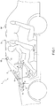
- reference numeral 1 indicates, as a whole, a road vehicle (in particular a car) provided with two front driven (i.e. not driving) wheels and two rear driving wheels. In a front position, an internal combustion engine is arranged, which produces a torque which is transmitted to the driving wheels via a transmission.
- the road vehicle 1 comprises a passenger compartment 2 which is provided with two or more seats 3 each adapted to accommodate a corresponding occupant 4; i.e. in the passenger compartment 2 a driver is always seated, with the addition of possible passengers (whose presence is obviously optional).
- the road vehicle 1 comprises an air conditioning system 5 which allows letting inside the passenger compartment 2 a plurality of air flows A in the passenger compartment 2.
- the air flows A can be both hot air flows (previously heated by means of resistors or by transmission of the heat of the endothermic engine), and cold air flows (by transmission of the heat with the evaporator).
- the terms "hot” and “cold” are respectively intended to mean hotter and colder with respect to an existing temperature on the inside of the vehicle 1.
- the air conditioning system 5 comprises a plurality of ventilation devices 6 arranged inside the passenger compartment 2 of the road vehicle 1 and through which the air flows A let in by the air conditioning system 5 transit inside the passenger compartment 2.
- the ventilation devices 6 are divided into three different categories based on the zone toward which such devices 6 direct the air flows A.
- the air conditioning system 5 comprises at least one ventilation device 6 for the defrosting (defrost), in which the respective air flow A is directed toward or along a windshield 7; at least one ventilation device 6 for the ventilation (vent) of the occupants 4, in which the respective air flow A is directed toward the body of the occupants 4; and at least one bottom device (down) directing the respective air flow A toward the feet of the occupants 4.
- the ventilation devices 6 are further divided based on the side of the vehicle on which they are positioned (for example, right side, left side and/or front side, rear side).
- the air conditioning system 5 further comprises a control unit 8, which is configured to control the ventilation devices 6.
- the control unit 8 determines the flow rate of the air flows A and the temperature of the same when flowing out of the ventilation devices 6 (i.e. from the nozzles).
- the air conditioning system 5 (in particular the control unit 8) comprises a memory 9 inside which the adjustment parameters are saved. More specifically, such adjustment parameters are saved so as to keep track of the preferences of the occupants 4.
- control system 5 comprises at least one sensor member 10 configured to identify at least the number and the position (for example on which seat they are seated) of the occupants 4 inside the passenger compartment 2.
- the sensor member 10 comprises (in particular, is) a thermal camera 11 configured to frame one or more occupants 4 of the passenger compartment 2 and determine the temperature of at least a part of the body of at least one occupant 4.
- the thermal camera 11 communicates the data detected to the control unit 8.
- the thermal camera 11 communicates the data detected to a suitable image processing system, which is connected to the control unit 8.
- the thermal camera 11 is arranged at a ceiling light of the passenger compartment 2 (as illustrated in Figure 1 ).
- the thermal camera 11 is arranged in a central portion (above the rear-view mirror).
- the thermal camera 11 is arranged at a pillar of the passenger compartment 2.
- the thermal camera 11 is arranged in an upper portion of a pillar arranged between the base of a frame and the ceiling of the passenger compartment 2.
- the air conditioning system 5 comprises two thermal cameras 11, one facing the driver and one facing the passenger.
- the air conditioning system 5 comprises at least three thermal cameras 11, of which one facing the driver, one facing the passenger and one facing the back seats 3.
- the air conditioning system 5 comprises at least one thermometer 13 arranged inside the passenger compartment 2.
- the thermometer 13 is arranged in a position difficult to be accessed by the occupants 4 such as, for example, the inside of a central dashboard or the lower part of a seat 3.
- the air conditioning system 5 also comprises an irradiation sensor 14, which is configured to determine the direction and the intensity of the solar radiations with respect to the vehicle 1.
- the irradiation sensor 14 communicates the data detected to the control unit 8.
- the control system 5 further comprises a processing device 12, which determines an optimized tuning based on the detection of the sensor member 10 and controls the ventilation devices 6 based on the optimized tuning.
- a method for controlling the air conditioning system 5 is provided.
- the control method comprises the step of detecting, by means of the sensor member 10, a body temperature of at least a part of the body of an occupant 4 of the passenger compartment 2; and the step of providing (i.e. communicating) such detected body temperature to the air conditioning system 5, in particular to the calculation unit 8.
- the method comprises the further step of identifying the number and the position of the occupants 4 inside the passenger compartment 2. More specifically, during this step which of the seats 3 are actually occupied by an occupant 4 is defined.
- the method comprises a step of determining an optimized tuning at least based on the body temperature detected by the sensor member, and controlling the ventilation devices 6 accordingly (i.e. as a function of the optimized tuning).
- the optimized tuning changes depending on the driving style of an occupant (i.e. of the driver of the vehicle 1), which is determined based on the data detected, in particular, by means of an inertial measuring unit (known per se and not illustrated).
- the driving style of the driver is defined based on, at least, the longitudinal acceleration (A L in Figure 4 ), the lateral or transverse acceleration (A T in Figure 4 ) and the speed.
- Such parameters are processed according to known models which determine a driving value by calculating a weighted average of the aforementioned measurements and comparing it with reference parameters.
- the optimized tuning changes upon the variation of the at least one body temperature of a part of the body of at least one of the occupants 4 of the passenger compartment 2.
- the sensor device 10 i.e. the thermal camera 11, frames at least one occupant 4 so as to view the upper portion of the body thereof (in other words, anything above the waist of the occupant 4).
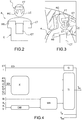
- the non-limiting embodiment of Figure 2 illustrates schematically a division of the upper portion of an occupant 4.
- the thermal camera 11 detects a plurality of different temperatures relating to the framed occupant 4. More specifically, the thermal camera 11 calculates an average of the temperature of a certain part of the body of the occupant 4, providing a scalar value to the control unit 8 relating to that part of the body.
- the upper portion of an occupant 4 is schematically divided macroscopically into head T and trunk C.
- a forehead temperature FT is detected.
- temperatures RC and LC of the right cheek and of the left cheek of the occupant, respectively, are detected.
- a chest and/or abdomen temperature CT is detected in relation to the trunk C. Specifically, also temperatures RT and LT of the right and of the left of the occupant, respectively, are detected.
- the temperatures RT and LT are the temperatures of the shoulders and/or of the right and left arms of the occupant 4 framed by the thermal camera 11.
- the optimized tuning changes depending on the build of at least one of the occupants 4.
- build is intended to mean the body type of the occupant 4.
- the build of the occupant 4 is determined by means of the thermal camera 11.
- the build is identified in terms of a body index BI (as indicated in Figure 4 ).
- body index BI is obtained by outlining the images obtained from the thermal camera 11 to determine the dimensions of the body of the occupant 4.
- the body index BI takes into consideration the weight of the occupant 11 (detected, for example, with a load sensor comprised in a seat 3).
- the optimized tuning changes depending on the clothes worn by the occupant 4 of the vehicle 1 ( Figure 3 ), for example by the driver.
- a clothing index CI ( Figure 4 ) is determined which determines the thermal insulation of the occupant 4 due to the clothes and with respect to the temperature inside the passenger compartment.
- the clothes of the occupants 4 are determined based on a difference between the body temperature of a part of the body covered by the clothes and the body temperature of an uncovered part of the body.
- the clothing index CI is determined based on the difference between the head temperature T (in particular the forehead temperature FT) of the occupant 4 and the trunk temperature C (in particular the chest and/or abdomen temperature CT).
- the optimized tuning changes depending on the gender of the occupant 4.
- the gender of the occupant is determined as a function of a personal opening key used to open the vehicle 1, or by means of a voice recognition system present on board the vehicle 1, or by means of a driving style or by means of the weight detected by the seat 3.
- the air conditioning system 5 can adjust in such sense, and in a differentiated manner, a two-zone, three-zone or four-zone air conditioning.
- the optimized tuning changes depending on the head temperature T (for example FT).
- the head T is generally the part of the body with the greatest temperature variability or in any case the part from which it is easier to understand the thermal state of an occupant 4 (for example, whether said occupant is hot or cold).
- the thermal state of an occupant 4 for example, whether said occupant is hot or cold.
- the optimized tuning changes based on the irradiation I ( Figure 4 ) of the road vehicle 1.
- the value of the irradiation I of the road vehicle 1 is processed (by the control unit 8) based on the difference between the body temperature RT of a right part of the body and the body temperature LT of a left part of the body of at least one of the occupants 4 and detected using the thermal camera 11.
- the value of the irradiation I of the road vehicle 1 is processed taking into account the detection of the irradiation sensor 14 installed on board the vehicle 1.
- the optimized tuning changes depending on the temperature ET on the outside of the passenger compartment 2.
- the temperature ET on the outside of the passenger compartment 2 is processed based on the temperature of at least one window, detected by means of the thermal camera 11 arranged inside the passenger compartment 2.
- the temperature ET on the outside of the passenger compartment 2 is processed taking into account the detection of a thermometer on the outside of the passenger compartment (arranged, for example, in the lower part of the body of the vehicle 1).
- the method comprises the further steps of detecting a temperature on the inside of the passenger compartment 2 by means of at least the thermometer 13 (arranged inside the passenger compartment 2) and refining the optimized tuning based on the inside temperature detected by the thermometer 13.
- the control method comprises the step of setting (only once, i.e. not continuously in a cyclical manner) a desired temperature by means of an interface device, known per se and thus not illustrated (for example, a push-button panel, a voice command, a wheel, etc.).
- This step is preferably performed by an occupant 4 of the vehicle 1, for example a driver, who sets a desired temperature that he or she considers consistent with his or her habits and with the existing temperature perception inside the passenger compartment (i.e. if said occupant is hot or cold).
- the method further provides a comparison of the temperature on the inside of the passenger compartment 2 with the desired set temperature and refining the optimized tuning based on a difference between the temperature on the inside of the passenger compartment 2 and the desired temperature.
- the method for controlling the air conditioning system 5 comprises the further step of adjusting a flow rate and/or a temperature of the air flows A flowing out of the plurality of ventilation devices 6 arranged inside the passenger compartment 2.
- the temperature and the flow rate of the air flows A are adjusted independently of one another. More specifically, the temperature and the flow rate of the air flows A are adjusted independently between the different ventilation devices 6. This way, it is possible to increase the comfort of the occupants 4 of the vehicle taking into account all the considerations set out above.
- the ventilation devices 6 arranged on that side will emit an air flow A at a lower temperature with respect to the air flow emitted at the same moment by the ventilation devices 6 arranged on the side in the shade of the vehicle 1 (i.e. the side opposite the one irradiated by the sun).
- the optimized tuning changes depending on a thermal comfort index TI which takes into consideration part or all of the variables up to now described and detected.
- the thermal index TI is obtained by calculating a weighted average between: the outside data ED (relating to the outside temperature ET and the irradiation I); the body data BD (relating to the temperatures and/or the data FT, RC, LC, RT, LT, CT, CI detected or obtained by means of the images displayed by the thermal camera 11); the body index IB (relating to the build of the occupants 4) and the dynamic model DM (obtained as a function of the longitudinal and lateral accelerations A L , A T and of the speed V of the vehicle 1) .
- the outside data ED relating to the outside temperature ET and the irradiation I
- the body data BD relating to the temperatures and/or the data FT, RC, LC, RT, LT, CT, CI detected or obtained by means of the images displayed by the thermal camera 11
- the body index IB relating to the build of the occupants 4
- the dynamic model DM obtained as a function of the longitudinal and lateral accelerations
- the data relating to the temperatures FT, RC, LC, RT, LT, CT detected by the thermal camera 11 generate a value K, which is used, together with a metabolic index MR obtained from the data of the dynamic model DM (depending on the driving style) and of the body index of the occupants 4, in order to process the thermal index IT.
- a metabolic index MR obtained from the data of the dynamic model DM (depending on the driving style) and of the body index of the occupants 4, in order to process the thermal index IT.
- the type of driving is also taken into account.
- the correlation between build and gender is used to calculate the related metabolic index MR.
- the value K already takes into account also the outside data ED.
- the model of Hagino and Junichiro which takes into account the relative importance (weight) of the local temperatures on the general thermal comfort index TI.
- At least part of the (in particular all of the) data/values used for calculating the thermal index TI are each multiplied by a coefficient, so that the thermal index TI is a weighted average.
- the coefficients k 1 -k 6 and the offsets Off, O 1 -O 6 are determined experimentally, by means of allocation tables which allow the allocation of a specific coefficient based on the desired weight of the variable multiplied by such coefficient and the performance of a calibration by means of the offsets which allows adapting the optimized tuning to different vehicle models.
- the sum of the coefficients k 1 -k 6 is preferably equal to one.
- the offset Off is a parameter used for setting a preference of the occupant 4 and saving it in the memory 9.
- the offset Off allows the system 5 to take into account the preference of said occupant and to change it as soon as the occupant 4 is recognized in accordance with one of the methods described in the foregoing.
- the thermal index TI (which is also multiplied by a predefined weight) is added to the data ED relating to the outside of the vehicle 1 and the data relating to the inside of the vehicle, but not obtained from the thermal camera (i.e. the temperature T IN detected by means of the thermometer 13) on the inside of the passenger compartment 2 and the discharge temperature T DIS of the air flows A at the ventilation devices 6 (more specifically at the nozzles).
- the coefficients Q 1 -Q 5 are determined experimentally, by means of allocation tables which allow allocating a given coefficient based on the desired weight of the variable multiplied by such coefficient.
- the sum of the coefficients Q 1 -Q 5 is preferably equal to one.
- the thermal index TI represents the additional component to the formula of the equivalent temperature T EQ .
- everything is maintained as an open-loop control, in which, at an increase of the thermal index TI, its equivalent temperature T EQ increases and thus the outflowing discharge temperature ⁇ decreases, while, at the decrease of the thermal index, its equivalent temperature T EQ also decreases and thus the outflowing discharge temperature ⁇ increases.
- the control is a closed-loop control in which the thermal index TI represents the feedback of the equivalent temperature T EQ .
- the flow rate of the air flows A flowing out of the discharge devices 6 increases proportionally to the increase in the difference between the thermal index TI and the equivalent temperature T EQ .
- an occupant 4 boarding the vehicle 1 defines a desired temperature signal by means of an interface device known per se and thus not illustrated.
- the processing device 12 identifies, using, for example, the sensor member 10 or weight sensors arranged at the seats 3, the number and the position of the occupants 4 seated in the passenger compartment 2, determines an optimized tuning based on all the parameters described in the foregoing and as illustrated in Figure 4 , and thus controls (adjusts) the temperature and the flow rate of the air flows A flowing out of the ventilation devices 6 depending on the optimized tuning.
- the optimized tuning changes upon the variation of the number and/or the position of the occupants 4 in the passenger compartment 2 and of the parameters described above; i.e.
- the thermal camera 11 will exclusively detect the body data and the temperatures relating solely to the driver and will adapt the air flows A so as to compensate possible variations in the outside (temperature, irradiation) or inside (clothing, diversified temperatures for different parts of the body, etc.) conditions.
- the ventilation devices 6 must be controlled taking into account the needs of both of occupants (detected, for example, by means of a plurality of thermal cameras 11) in order to optimize the climatic perception of both occupants without privileging (excessively) one at the expense of the other.
- the processing device 12 controls the ventilation devices so as to obtain a thermal condition which satisfies, at least partially, all occupants.
- the air conditioning system 5 is controlled so as to reach an average thermal condition with respect to the optimal needs of the occupants 4 of the passenger compartment 2.
- control method described above has numerous advantages.
- the control method described above allows optimizing the control of an air conditioning system 5 as it has been observed that the perception of the temperature by the occupants 4 seated in the passenger compartment 2 is significantly influenced by the number, by the arrangement of the occupants 4, by the solar irradiation, by the clothing of the occupants, by their body type, etc. Moreover, the passenger compartment 2 has a small and complex (i.e. full of elements of different shapes) volume and the addition or the subtraction of a single occupant perceptibly modifies the thermal response of the passenger compartment 2.
- control method described above functions in an entirely automatic manner, i.e. transparent with respect to the occupants 4, and can thus be used by anybody (not requiring any actions) without entailing any type of distraction while driving.
- the processing device 12 can in fact be developed entirely via software in one of the existing control units or in the hardware of the air conditioning system 5, while the thermal camera 14, the irradiation sensor, the thermometer 13 and the weight sensors are already present in the passenger compartment 2 for other purposes.
Landscapes
- Engineering & Computer Science (AREA)
- Physics & Mathematics (AREA)
- Mechanical Engineering (AREA)
- Thermal Sciences (AREA)
- Multimedia (AREA)
- Signal Processing (AREA)
- Health & Medical Sciences (AREA)
- Toxicology (AREA)
- Life Sciences & Earth Sciences (AREA)
- Sustainable Development (AREA)
- General Physics & Mathematics (AREA)
- Theoretical Computer Science (AREA)
- Air-Conditioning For Vehicles (AREA)
- Air Conditioning Control Device (AREA)
Abstract
Description
- This patent application claims priority from Italian patent application no.
102020000002665 filed on February 11, 2020 - The present invention relates to a method to control an air conditioning system in a passenger compartment of a road vehicle.
- Modern road vehicles are substantially always equipped with an air conditioning system which allows adjusting (increasing, decreasing or keeping constant) the temperature inside the vehicle (i.e. a passenger compartment). By way of example, the air conditioning system is frequently used during the summer season to lower the temperature on the inside of the passenger compartment with respect to the temperature on the outside of the vehicle; conversely, during the winter season, the air conditioning system is generally used to heat the inside of the passenger compartment so as to have a higher temperature with respect to the outside.
- An air conditioning system normally comprises a plurality of ventilation devices (comprising the so-called air "nozzles") arranged in different positions on the inside of the passenger compartment of the road vehicle. For example, the ventilation devices can be divided by types based on the zone toward which they direct an air flow and can be independently adjusted and/or selectively activated.
- Modern air conditioning systems have ample possibilities for adjusting the modalities with which the temperature on the inside of the passenger compartment is adjusted. For example, by operating each ventilation device in a completely independent manner, it is possible to manually increase or decrease the flow rate (i.e. the intensity) and/or the direction of the air flow emitted by each ventilation device.
- Moreover, automatic (both single-zone and two-zone) air conditioning systems are more and more common, which adjust the intensity and the temperature of the air based on an inside temperature detected by one or more thermometers arranged on the inside of the passenger compartment (for example, under a seat, inside a dashboard or a console). This inside temperature is usually used for a closed-loop (feedback) control which adjusts the temperature and the intensity of the air flow flowing out of the ventilation devices, so as to reach the temperature set manually by one (or two, in the case of a two-zone system) of the occupants.
- However, these ample adjustment possibilities are simply based on reaching the set temperature on the inside of the passenger compartment, without actually considering the real thermal conditions, the real presence and the actual position of the occupants of the passenger compartment of the road vehicle. For these reasons, generally, the desired manually set temperature is periodically modified by the driver or by a passenger so as to adapt said desired inside temperature to the immediate needs of those seated inside the vehicle.
- For example, in the systems of the prior art, by setting a certain desired temperature value, the air conditioning system works to reach such average temperature on the inside of the passenger compartment, without considering the needs and the habits of the occupants and without evaluating what incidence the solar irradiation has in the temperature distribution on the inside of the passenger compartment of the road vehicle.
- The object of the present invention, among others, is to provide a method for controlling an air conditioning system in a passenger compartment of a road vehicle, which control method allows improving (optimizing) the climatic perception on the inside of the passenger compartment by one or more occupants and, at the same time, is easily and immediately usable for all the users and does not distract the driver from driving.
- According to the present invention, a method for controlling an air conditioning system in a passenger compartment of a road vehicle is provided, according to what claimed by the appended claims.
- The claims describe preferred embodiments of the present invention constituting an integral part of the present description.
- The present invention will now be described with reference to the accompanying drawings, which illustrate a non-limiting embodiment example thereof, wherein:
-
Figure 1 is a schematic and side view of a road vehicle equipped with an air conditioning system which is controlled according to the control method of the present invention; -
Figure 2 illustrates schematically and frontally a division into thermal areas of the bust of an occupant of the passenger compartment; -
Figure 3 is a perspective and schematic view of the field of vision of a sensor member inside the passenger compartment; -
Figure 4 illustrates a possible flowchart for determining a thermal index. - In
Figure 1 , reference numeral 1 indicates, as a whole, a road vehicle (in particular a car) provided with two front driven (i.e. not driving) wheels and two rear driving wheels. In a front position, an internal combustion engine is arranged, which produces a torque which is transmitted to the driving wheels via a transmission. - The road vehicle 1 comprises a
passenger compartment 2 which is provided with two ormore seats 3 each adapted to accommodate acorresponding occupant 4; i.e. in the passenger compartment 2 a driver is always seated, with the addition of possible passengers (whose presence is obviously optional). - The road vehicle 1 comprises an
air conditioning system 5 which allows letting inside the passenger compartment 2 a plurality of air flows A in thepassenger compartment 2. The air flows A can be both hot air flows (previously heated by means of resistors or by transmission of the heat of the endothermic engine), and cold air flows (by transmission of the heat with the evaporator). The terms "hot" and "cold" are respectively intended to mean hotter and colder with respect to an existing temperature on the inside of the vehicle 1. - In the non-limiting embodiment of
Figure 1 , theair conditioning system 5 comprises a plurality ofventilation devices 6 arranged inside thepassenger compartment 2 of the road vehicle 1 and through which the air flows A let in by theair conditioning system 5 transit inside thepassenger compartment 2. In particular, theventilation devices 6 are divided into three different categories based on the zone toward whichsuch devices 6 direct the air flows A. For example, theair conditioning system 5 comprises at least oneventilation device 6 for the defrosting (defrost), in which the respective air flow A is directed toward or along a windshield 7; at least oneventilation device 6 for the ventilation (vent) of theoccupants 4, in which the respective air flow A is directed toward the body of theoccupants 4; and at least one bottom device (down) directing the respective air flow A toward the feet of theoccupants 4. - In some non-limiting cases, the
ventilation devices 6 are further divided based on the side of the vehicle on which they are positioned (for example, right side, left side and/or front side, rear side). - The
air conditioning system 5 further comprises acontrol unit 8, which is configured to control theventilation devices 6. In particular, thecontrol unit 8 determines the flow rate of the air flows A and the temperature of the same when flowing out of the ventilation devices 6 (i.e. from the nozzles). - Advantageously but not necessarily, the air conditioning system 5 (in particular the control unit 8) comprises a memory 9 inside which the adjustment parameters are saved. More specifically, such adjustment parameters are saved so as to keep track of the preferences of the
occupants 4. - Advantageously, the
control system 5 comprises at least onesensor member 10 configured to identify at least the number and the position (for example on which seat they are seated) of theoccupants 4 inside thepassenger compartment 2. - Advantageously but not necessarily, the
sensor member 10 comprises (in particular, is) athermal camera 11 configured to frame one ormore occupants 4 of thepassenger compartment 2 and determine the temperature of at least a part of the body of at least oneoccupant 4. In some non-limiting cases, thethermal camera 11 communicates the data detected to thecontrol unit 8. In other non-limiting cases, thethermal camera 11 communicates the data detected to a suitable image processing system, which is connected to thecontrol unit 8. - According to some non-limiting embodiments, the
thermal camera 11 is arranged at a ceiling light of the passenger compartment 2 (as illustrated inFigure 1 ). In particular, thethermal camera 11 is arranged in a central portion (above the rear-view mirror). - According to other non-limiting embodiments, the
thermal camera 11 is arranged at a pillar of thepassenger compartment 2. In particular, thethermal camera 11 is arranged in an upper portion of a pillar arranged between the base of a frame and the ceiling of thepassenger compartment 2. - In some non-limiting cases, especially in the case of a two-seater vehicle, the
air conditioning system 5 comprises twothermal cameras 11, one facing the driver and one facing the passenger. - In other non-limiting cases, especially in the case of a vehicle provided with
back seats 3, theair conditioning system 5 comprises at least threethermal cameras 11, of which one facing the driver, one facing the passenger and one facing theback seats 3. - According to the non-limiting embodiment of
Figure 1 , theair conditioning system 5 comprises at least onethermometer 13 arranged inside thepassenger compartment 2. In particular, thethermometer 13 is arranged in a position difficult to be accessed by theoccupants 4 such as, for example, the inside of a central dashboard or the lower part of aseat 3. - Advantageously but not necessarily, the
air conditioning system 5 also comprises anirradiation sensor 14, which is configured to determine the direction and the intensity of the solar radiations with respect to the vehicle 1. In particular, theirradiation sensor 14 communicates the data detected to thecontrol unit 8. - The
control system 5 further comprises aprocessing device 12, which determines an optimized tuning based on the detection of thesensor member 10 and controls theventilation devices 6 based on the optimized tuning. - According to a further aspect of the present invention, a method for controlling the
air conditioning system 5 is provided. - The control method comprises the step of detecting, by means of the
sensor member 10, a body temperature of at least a part of the body of anoccupant 4 of thepassenger compartment 2; and the step of providing (i.e. communicating) such detected body temperature to theair conditioning system 5, in particular to thecalculation unit 8. - Advantageously, the method comprises the further step of identifying the number and the position of the
occupants 4 inside thepassenger compartment 2. More specifically, during this step which of theseats 3 are actually occupied by anoccupant 4 is defined. - Additionally, the method comprises a step of determining an optimized tuning at least based on the body temperature detected by the sensor member, and controlling the
ventilation devices 6 accordingly (i.e. as a function of the optimized tuning). - Advantageously but not necessarily, the optimized tuning changes depending on the driving style of an occupant (i.e. of the driver of the vehicle 1), which is determined based on the data detected, in particular, by means of an inertial measuring unit (known per se and not illustrated). The driving style of the driver is defined based on, at least, the longitudinal acceleration (AL in
Figure 4 ), the lateral or transverse acceleration (AT inFigure 4 ) and the speed. Such parameters are processed according to known models which determine a driving value by calculating a weighted average of the aforementioned measurements and comparing it with reference parameters. - Advantageously but not necessarily, the optimized tuning changes upon the variation of the at least one body temperature of a part of the body of at least one of the
occupants 4 of thepassenger compartment 2. - Advantageously but not necessarily, the
sensor device 10, i.e. thethermal camera 11, frames at least oneoccupant 4 so as to view the upper portion of the body thereof (in other words, anything above the waist of the occupant 4). - The non-limiting embodiment of
Figure 2 illustrates schematically a division of the upper portion of anoccupant 4. In particular, according to such division, thethermal camera 11 detects a plurality of different temperatures relating to the framedoccupant 4. More specifically, thethermal camera 11 calculates an average of the temperature of a certain part of the body of theoccupant 4, providing a scalar value to thecontrol unit 8 relating to that part of the body. - In the non-limiting embodiment of
Figure 2 , the upper portion of anoccupant 4 is schematically divided macroscopically into head T and trunk C. - Preferably, in relation to the head T, a forehead temperature FT is detected. Specifically, also temperatures RC and LC of the right cheek and of the left cheek of the occupant, respectively, are detected.
- Advantageously but not necessarily, in relation to the trunk C, a chest and/or abdomen temperature CT is detected. Specifically, also temperatures RT and LT of the right and of the left of the occupant, respectively, are detected. The temperatures RT and LT are the temperatures of the shoulders and/or of the right and left arms of the
occupant 4 framed by thethermal camera 11. - Advantageously but not necessarily, the optimized tuning changes depending on the build of at least one of the
occupants 4. The term "build" is intended to mean the body type of theoccupant 4. - According to some non-limiting embodiments, the build of the
occupant 4 is determined by means of thethermal camera 11. In particular, the build is identified in terms of a body index BI (as indicated inFigure 4 ). Such body index BI is obtained by outlining the images obtained from thethermal camera 11 to determine the dimensions of the body of theoccupant 4. Alternatively or additionally, the body index BI takes into consideration the weight of the occupant 11 (detected, for example, with a load sensor comprised in a seat 3). - Advantageously but not necessarily, the optimized tuning changes depending on the clothes worn by the
occupant 4 of the vehicle 1 (Figure 3 ), for example by the driver. In particular, via thethermal camera 11, a clothing index CI (Figure 4 ) is determined which determines the thermal insulation of theoccupant 4 due to the clothes and with respect to the temperature inside the passenger compartment. - Advantageously but not necessarily, the clothes of the
occupants 4 are determined based on a difference between the body temperature of a part of the body covered by the clothes and the body temperature of an uncovered part of the body. - According to some non-limiting embodiments, the clothing index CI is determined based on the difference between the head temperature T (in particular the forehead temperature FT) of the
occupant 4 and the trunk temperature C (in particular the chest and/or abdomen temperature CT). - Advantageously but not necessarily, the optimized tuning changes depending on the gender of the
occupant 4. - In some non-limiting cases, the gender of the occupant is determined as a function of a personal opening key used to open the vehicle 1, or by means of a voice recognition system present on board the vehicle 1, or by means of a driving style or by means of the weight detected by the
seat 3. In such manner, it is possible to customize the optimized tuning of theair conditioning system 5 so that, in the case in which the occupant is a man, the temperature of the air flowing out of theventilation devices 6 is slightly lower (or higher) with respect to the case in which the occupant is a woman. In particular, theair conditioning system 5 can adjust in such sense, and in a differentiated manner, a two-zone, three-zone or four-zone air conditioning. - According to some non-limiting embodiments, the optimized tuning changes depending on the head temperature T (for example FT). The head T is generally the part of the body with the greatest temperature variability or in any case the part from which it is easier to understand the thermal state of an occupant 4 (for example, whether said occupant is hot or cold). In such manner, at the increase of the head temperature T, it is possible to reduce the average temperature inside the passenger compartment accordingly because it would mean that the
occupant 4 is getting hot (this is obviously also valid in the converse case). - Advantageously but not necessarily, the optimized tuning changes based on the irradiation I (
Figure 4 ) of the road vehicle 1. - According to some non-limiting embodiments, the value of the irradiation I of the road vehicle 1 is processed (by the control unit 8) based on the difference between the body temperature RT of a right part of the body and the body temperature LT of a left part of the body of at least one of the
occupants 4 and detected using thethermal camera 11. - Alternatively or additionally, the value of the irradiation I of the road vehicle 1 is processed taking into account the detection of the
irradiation sensor 14 installed on board the vehicle 1. - Advantageously but not necessarily, the optimized tuning changes depending on the temperature ET on the outside of the
passenger compartment 2. - According to some non-limiting embodiments such as the one illustrated in
Figure 3 , the temperature ET on the outside of thepassenger compartment 2 is processed based on the temperature of at least one window, detected by means of thethermal camera 11 arranged inside thepassenger compartment 2. - Alternatively or additionally, the temperature ET on the outside of the
passenger compartment 2 is processed taking into account the detection of a thermometer on the outside of the passenger compartment (arranged, for example, in the lower part of the body of the vehicle 1). - Advantageously but not necessarily, the method comprises the further steps of detecting a temperature on the inside of the
passenger compartment 2 by means of at least the thermometer 13 (arranged inside the passenger compartment 2) and refining the optimized tuning based on the inside temperature detected by thethermometer 13. - In some non-limiting cases, the control method comprises the step of setting (only once, i.e. not continuously in a cyclical manner) a desired temperature by means of an interface device, known per se and thus not illustrated (for example, a push-button panel, a voice command, a wheel, etc.). This step is preferably performed by an
occupant 4 of the vehicle 1, for example a driver, who sets a desired temperature that he or she considers consistent with his or her habits and with the existing temperature perception inside the passenger compartment (i.e. if said occupant is hot or cold). In particular, the method further provides a comparison of the temperature on the inside of thepassenger compartment 2 with the desired set temperature and refining the optimized tuning based on a difference between the temperature on the inside of thepassenger compartment 2 and the desired temperature. - Advantageously but not necessarily, the method for controlling the
air conditioning system 5 comprises the further step of adjusting a flow rate and/or a temperature of the air flows A flowing out of the plurality ofventilation devices 6 arranged inside thepassenger compartment 2. In particular, the temperature and the flow rate of the air flows A are adjusted independently of one another. More specifically, the temperature and the flow rate of the air flows A are adjusted independently between thedifferent ventilation devices 6. This way, it is possible to increase the comfort of theoccupants 4 of the vehicle taking into account all the considerations set out above. For example, if the solar irradiation predominantly hits one side of the vehicle 1, theventilation devices 6 arranged on that side will emit an air flow A at a lower temperature with respect to the air flow emitted at the same moment by theventilation devices 6 arranged on the side in the shade of the vehicle 1 (i.e. the side opposite the one irradiated by the sun). - Advantageously but not necessarily, the optimized tuning changes depending on a thermal comfort index TI which takes into consideration part or all of the variables up to now described and detected.
- In the non-limiting embodiment of
Figure 4 , the thermal index TI is obtained by calculating a weighted average between: the outside data ED (relating to the outside temperature ET and the irradiation I); the body data BD (relating to the temperatures and/or the data FT, RC, LC, RT, LT, CT, CI detected or obtained by means of the images displayed by the thermal camera 11); the body index IB (relating to the build of the occupants 4) and the dynamic model DM (obtained as a function of the longitudinal and lateral accelerations AL, AT and of the speed V of the vehicle 1) . - In particular, as illustrated in
Figure 4 , the data relating to the temperatures FT, RC, LC, RT, LT, CT detected by thethermal camera 11 generate a value K, which is used, together with a metabolic index MR obtained from the data of the dynamic model DM (depending on the driving style) and of the body index of theoccupants 4, in order to process the thermal index IT. In order to obtain a detailed index MR, in addition to the body index BI, the type of driving is also taken into account. - In particular, following the studies of Schaudienst and Vogdt, the correlation between build and gender (possibly also physical condition, by evaluating the temperature of the abdomen - the fat is less permeated than the muscle - or the silhouette of the occupant) is used to calculate the related metabolic index MR.
- According to some non-limiting embodiments, the value K already takes into account also the outside data ED. In particular, following the model of Hagino and Junichiro (known in the literature) which takes into account the relative importance (weight) of the local temperatures on the general thermal comfort index TI.
- Advantageously but not necessarily, at least part of the (in particular all of the) data/values used for calculating the thermal index TI are each multiplied by a coefficient, so that the thermal index TI is a weighted average.
- According to a non-limiting embodiment, the thermal index TI is expressed by the formula:


- In particular, the coefficients k1-k6 and the offsets Off, O1-O6 are determined experimentally, by means of allocation tables which allow the allocation of a specific coefficient based on the desired weight of the variable multiplied by such coefficient and the performance of a calibration by means of the offsets which allows adapting the optimized tuning to different vehicle models. The sum of the coefficients k1-k6 is preferably equal to one.
- Advantageously but not necessarily, the offset Off is a parameter used for setting a preference of the
occupant 4 and saving it in the memory 9. In particular, if anoccupant 4 has a certain thermal disposition, i.e. is on average hot or on average cold, the offset Off allows thesystem 5 to take into account the preference of said occupant and to change it as soon as theoccupant 4 is recognized in accordance with one of the methods described in the foregoing. - As illustrated in the non-limiting embodiment of
Figure 4 , the thermal index TI (which is also multiplied by a predefined weight) is added to the data ED relating to the outside of the vehicle 1 and the data relating to the inside of the vehicle, but not obtained from the thermal camera (i.e. the temperature TIN detected by means of the thermometer 13) on the inside of thepassenger compartment 2 and the discharge temperature TDIS of the air flows A at the ventilation devices 6 (more specifically at the nozzles). - According to a non-limiting embodiment, an equivalent (measured) temperature TEQ designed to determine the output temperature of the air flows A is expressed by the formula:

- In particular, the coefficients Q1-Q5 are determined experimentally, by means of allocation tables which allow allocating a given coefficient based on the desired weight of the variable multiplied by such coefficient. The sum of the coefficients Q1-Q5 is preferably equal to one.
- Specifically, the thermal index TI represents the additional component to the formula of the equivalent temperature TEQ. In this non-limiting case, everything is maintained as an open-loop control, in which, at an increase of the thermal index TI, its equivalent temperature TEQ increases and thus the outflowing discharge temperature θ decreases, while, at the decrease of the thermal index, its equivalent temperature TEQ also decreases and thus the outflowing discharge temperature θ increases. In other non-limiting cases, the control is a closed-loop control in which the thermal index TI represents the feedback of the equivalent temperature TEQ.
- Advantageously but not necessarily, the flow rate of the air flows A flowing out of the
discharge devices 6 increases proportionally to the increase in the difference between the thermal index TI and the equivalent temperature TEQ. - In use, an
occupant 4 boarding the vehicle 1 defines a desired temperature signal by means of an interface device known per se and thus not illustrated. - The embodiments described herein can be combined with one another without departing from the protection scope of the present invention.
- In use, the
processing device 12 identifies, using, for example, thesensor member 10 or weight sensors arranged at theseats 3, the number and the position of theoccupants 4 seated in thepassenger compartment 2, determines an optimized tuning based on all the parameters described in the foregoing and as illustrated inFigure 4 , and thus controls (adjusts) the temperature and the flow rate of the air flows A flowing out of theventilation devices 6 depending on the optimized tuning. Obviously, the optimized tuning changes upon the variation of the number and/or the position of theoccupants 4 in thepassenger compartment 2 and of the parameters described above; i.e. when the number and/or the position of theoccupants 4 of thepassenger compartment 2 modifies, when the outside data ED or the temperatures contained in the block K ofFigure 4 are modified, or when theoccupants 4 change and the metabolic index MR is modified, also the optimized tuning must consequently be modified. - For example, if only the driver is present, then the
thermal camera 11 will exclusively detect the body data and the temperatures relating solely to the driver and will adapt the air flows A so as to compensate possible variations in the outside (temperature, irradiation) or inside (clothing, diversified temperatures for different parts of the body, etc.) conditions. - Obviously, if both the driver and the front seat passenger (or also other passengers) are present, the
ventilation devices 6 must be controlled taking into account the needs of both of occupants (detected, for example, by means of a plurality of thermal cameras 11) in order to optimize the climatic perception of both occupants without privileging (excessively) one at the expense of the other. - Obviously, if there is only a single thermal camera present in the vehicle, the same can frame a plurality of
occupants 4. In the case in which there is a single-zone system and a plurality ofoccupants 4, theprocessing device 12 controls the ventilation devices so as to obtain a thermal condition which satisfies, at least partially, all occupants. In other words, theair conditioning system 5 is controlled so as to reach an average thermal condition with respect to the optimal needs of theoccupants 4 of thepassenger compartment 2. - Although the above-described invention makes particular reference to a very precise embodiment example, it is not to be considered limited to such embodiment example, all the variants, modifications or simplifications covered by the appended claims falling within its scope, such as, for example, a different type of sensors, a different type of vehicle, a different parametrization of the coefficients and of the offsets, etc.
- The control method described above has numerous advantages.
- First, the control method described above allows optimizing the control of an
air conditioning system 5 as it has been observed that the perception of the temperature by theoccupants 4 seated in thepassenger compartment 2 is significantly influenced by the number, by the arrangement of theoccupants 4, by the solar irradiation, by the clothing of the occupants, by their body type, etc. Moreover, thepassenger compartment 2 has a small and complex (i.e. full of elements of different shapes) volume and the addition or the subtraction of a single occupant perceptibly modifies the thermal response of thepassenger compartment 2. - Therefore, thanks to the control method described above, it is possible to provide, in particular when only the driver is present, or when the driver and a passenger are present (in the case of a two-zone system), a thermal condition which is simultaneously adaptive and customizable.
- Obviously, when increasing the number of the
occupants 4 of thepassenger compartment 2, the customization and the adaptability of the system inevitably decreases having to accept compromises in favour of the passengers, but it is anyway possible to reach the best possible compromise in order to maximize the quality of the thermal comfort perceived by alloccupants 4. - The control method described above functions in an entirely automatic manner, i.e. transparent with respect to the
occupants 4, and can thus be used by anybody (not requiring any actions) without entailing any type of distraction while driving. - Finally, the control method described above does not entail any increase in costs: the
processing device 12 can in fact be developed entirely via software in one of the existing control units or in the hardware of theair conditioning system 5, while thethermal camera 14, the irradiation sensor, thethermometer 13 and the weight sensors are already present in thepassenger compartment 2 for other purposes. -
- 1
- road vehicle
- 2
- passenger compartment
- 3
- seats
- 4
- occupant/s
- 5
- air conditioning system
- 6
- ventilation device
- 7
- windshield
- 8
- memory
- 9
- control unit
- 10
- sensor member
- 11
- thermal camera
- 12
- processing device
- 13
- thermometer
- 14
- irradiation sensor
- ED
- outside data
- ET
- outside temperature
- I
- irradiation
- BI
- body index
- AL
- longitudinal acceleration
- AT
- lateral acceleration
- V
- speed
- DM
- dynamic model
- MR
- metabolic index
- T
- head
- C
- trunk
- FT
- forehead temperature
- RC
- right cheek temperature
- LC
- left cheek temperature
- CT
- chest and/or abdomen temperature
- RT
- right temperature
- LT
- left temperature
- BD
- body data
- CI
- clothing index
- TI
- thermal index
- TIN
- inside temperature
- TDIS
- discharge temperature
- TEQ
- equivalent temperature
Claims (15)
- A method to control an air conditioning system (5) in a passenger compartment (2) of a road vehicle (1); the control method comprises the steps of:detecting, by means of a sensor member (10), a body temperature of at least a part of the body of one or more occupants (4) of the passenger compartment (2); andtransmitting the detected body temperature to the air conditioning system (5), which controls a plurality of ventilation devices (6) arranged in the passenger compartment (2);the control method is characterized in that it comprises the further steps of:identifying the number and the position of said one or more occupants (4) seated in the passenger compartment (2);determining an optimized tuning by calculating a thermal index (TI) at least based on the body temperature detected by the sensor member (10); andcontrolling the ventilation devices (6) as a function of the optimized tuning;wherein the optimized tuning changes depending on the driving style of an occupant (4), which is determined based on the data detected.
- The control method according to claim 1, wherein the driving style of an occupant (4) is determined by means of an inertial measuring unit.
- The control method according to claim 2, wherein the optimized tuning changes upon variation of said at least one body temperature of a part of the body of at least one of the occupants (4) of the passenger compartment (2).
- The control method according to claim 2 or 3, wherein the optimized tuning changes depending on the build of at least one of the occupants (4); in particular detected by means of the thermal camera (11).
- The control method according to one of the claims from 1 to 4, wherein the optimized tuning changes depending on a clothing index (CI) concerning the clothes worn by at least one of the occupants (4) of the passenger compartment (2) .
- The control method according to claim 5, wherein the clothing index (CI) is determined based on a difference between the body temperature of a part of the body covered by the clothes and the body temperature of an uncovered part of the body of at least one of the occupants (4); in particular a head.
- The control method according to one of the claims from 1 to 6, wherein the optimized tuning changes depending on the gender and/or on the temperature of the head of at least one of the occupants (4).
- The control method according to one of the claims from 1 to 7, wherein the optimized tuning changes depending on the irradiation of the road vehicle (1).
- The control method according to claim 8, wherein the irradiation of the road vehicle (1) is processed based on a signal detected by an outer irradiation sensor (14) and/or on a difference between a body temperature of a right part and a body temperature of a left part of the body of at least one of the occupants (4), which are detected using a thermal camera (11).
- The control method according to one of the claims from 1 to 9, wherein the optimized tuning changes based on the temperature on the outside of the passenger compartment (2); in particular, the temperature on the outside of the passenger compartment (2) is processed based on the temperature of at least one window, which is detected by means of a thermal camera (11) arranged inside the passenger compartment (2).
- The control method according to one of the claims from 1 to 10 and comprising the further steps of:detecting a temperature on the inside of the passenger compartment (2) by means of at least one thermometer (13) arranged inside the passenger compartment (2); andrefining the optimized tuning based on the inner temperature detected by said at least one thermometer (13).
- The control method according to claim 11 and comprising the further steps of:comparing the temperature on the inside of the passenger compartment (2) with the desired temperature; andrefining the optimized tuning based on a difference between the temperature on the inside of the passenger compartment (2) and a desired temperature.
- The control method according to one of the claims from 1 to 12 and comprising the further step of adjusting a flow rate and/or a temperature of an air flow flowing out of said plurality of ventilation devices (6) arranged in the passenger compartment (2).
- An air conditioning system (5) in a passenger compartment (2) of a road vehicle (1); the air conditioning system (5) comprises:an interface device to set a desired temperature signal;a plurality of ventilation devices (6) arranged in the passenger compartment (2);a control unit (8), which is configured to control said plurality of ventilation devices (6);the air conditioning system (5) is characterized in that it comprises:at least one sensor member (10) to identify at least the number and the position of the occupants (4) seated in the passenger compartment (2); anda processing device (12), which determines an optimized tuning based on the detection of the sensor member (10) and controls the ventilation devices (6) based on the optimized tuning.
- The air conditioning system (5) according to claim 14, wherein the sensor member (10) comprises at least one thermal camera (11), which is designed to frame one or more occupants (4) of the passenger compartment (2) and to determine the temperature of at least a part of the body of said at least one or more occupants (4) of the passenger compartment (2).
Applications Claiming Priority (1)
| Application Number | Priority Date | Filing Date | Title |
|---|---|---|---|
| IT102020000002665A IT202000002665A1 (en) | 2020-02-11 | 2020-02-11 | METHOD OF CONTROL OF AN AIR CONDITIONING SYSTEM IN A COCKPIT OF A ROAD VEHICLE |
Publications (2)
| Publication Number | Publication Date |
|---|---|
| EP3865325A1 true EP3865325A1 (en) | 2021-08-18 |
| EP3865325B1 EP3865325B1 (en) | 2024-06-26 |
Family
ID=70480606
Family Applications (1)
| Application Number | Title | Priority Date | Filing Date |
|---|---|---|---|
| EP21156486.9A Active EP3865325B1 (en) | 2020-02-11 | 2021-02-11 | Method to control an air conditioning system in a passenger compartment of a road vehicle |
Country Status (5)
| Country | Link |
|---|---|
| US (1) | US12583285B2 (en) |
| EP (1) | EP3865325B1 (en) |
| JP (1) | JP7760248B2 (en) |
| CN (1) | CN113246684B (en) |
| IT (1) | IT202000002665A1 (en) |
Cited By (2)
| Publication number | Priority date | Publication date | Assignee | Title |
|---|---|---|---|---|
| FR3135657A1 (en) * | 2022-05-20 | 2023-11-24 | Faurecia Interieur Industrie | Ventilation assembly for a vehicle, vehicle interior comprising such a ventilation assembly and associated control method |
| WO2025176713A1 (en) * | 2024-02-22 | 2025-08-28 | Jaguar Land Rover Limited | Target cabin temperature determination for hvac system of battery electric vehicle |
Families Citing this family (4)
| Publication number | Priority date | Publication date | Assignee | Title |
|---|---|---|---|---|
| US12269314B2 (en) * | 2022-06-16 | 2025-04-08 | GM Global Technology Operations LLC | Detecting and mitigating window condensation |
| CN115541271B (en) * | 2022-09-13 | 2025-11-07 | 岚图汽车科技有限公司 | Heat calculation method, device and equipment of four-zone air conditioner and storage medium |
| CN115675014B (en) * | 2022-11-29 | 2024-04-26 | 重庆赛力斯凤凰智创科技有限公司 | Vehicle air conditioner air outlet control method, device, computer equipment and storage medium |
| CN116749709A (en) * | 2023-06-05 | 2023-09-15 | 华南理工大学 | Crew cabin cooling and heating method and automobile based on local thermal comfort characteristics of human body |
Citations (8)
| Publication number | Priority date | Publication date | Assignee | Title |
|---|---|---|---|---|
| JP2004142567A (en) * | 2002-10-23 | 2004-05-20 | Denso Corp | Vehicle air conditioner |
| JP2005145327A (en) * | 2003-11-18 | 2005-06-09 | Calsonic Kansei Corp | Vehicular air conditioner |
| JP2006027557A (en) * | 2004-07-21 | 2006-02-02 | Matsushita Electric Ind Co Ltd | Blower |
| JP2006232007A (en) * | 2005-02-23 | 2006-09-07 | Fuji Heavy Ind Ltd | Air conditioner for vehicles |
| WO2016029044A1 (en) * | 2014-08-21 | 2016-02-25 | Proteq Technologies Llc | Climate control |
| WO2016070047A1 (en) * | 2014-10-31 | 2016-05-06 | Gentherm Inc. | Vehicle microclimate system and method of controlling same |
| DE102016215058A1 (en) * | 2016-08-12 | 2018-02-15 | Bayerische Motoren Werke Aktiengesellschaft | Improved control of the interior temperature |
| US20180244129A1 (en) * | 2017-02-27 | 2018-08-30 | Ford Global Technologies, Llc | Infrared sensor arrays for monitoring vehicle occupants and windows |
Family Cites Families (15)
| Publication number | Priority date | Publication date | Assignee | Title |
|---|---|---|---|---|
| JPH06344755A (en) * | 1993-06-02 | 1994-12-20 | Nissan Motor Co Ltd | Air-conditioning controller for vehicle |
| JPH0725219A (en) * | 1993-07-14 | 1995-01-27 | Mitsubishi Heavy Ind Ltd | Air conditioner for automobile |
| JPH10197348A (en) * | 1997-01-08 | 1998-07-31 | Zexel Corp | Thermal image processing method |
| JP2005047457A (en) * | 2003-07-31 | 2005-02-24 | Nissan Motor Co Ltd | Outside air temperature detection device and vehicle air conditioner |
| JP3938138B2 (en) * | 2003-11-10 | 2007-06-27 | 日産自動車株式会社 | Air conditioner for vehicles |
| US20060259219A1 (en) * | 2005-05-16 | 2006-11-16 | Denso Corporation | Vehicle climate control apparatus and method |
| JP2007308096A (en) * | 2006-05-22 | 2007-11-29 | Denso Corp | Air conditioner for vehicles |
| US20130145401A1 (en) * | 2011-11-16 | 2013-06-06 | Flextronics Ap, Llc | Music streaming |
| US9457639B2 (en) * | 2011-04-27 | 2016-10-04 | Mahle International Gmbh | System and method of providing quick thermal comfort with reduced energy by using directed spot conditioning |
| US8839632B2 (en) * | 2012-03-09 | 2014-09-23 | Visteon Global Technologies, Inc. | Control strategy for a zonal heating, ventilating, and air conditioning system of a vehicle |
| US9643471B2 (en) * | 2012-03-27 | 2017-05-09 | Ford Global Technologies, Llc | Driver personalized climate conditioning |
| KR101664684B1 (en) * | 2015-04-27 | 2016-10-10 | 현대자동차주식회사 | System and method for controlling air conditioner for vehicle |
| JP6505514B2 (en) * | 2015-06-10 | 2019-04-24 | パナソニック株式会社 | Air conditioner, sensor system, and method of estimating thermal sensation thereof |
| JP2017032268A (en) * | 2015-07-31 | 2017-02-09 | パナソニックIpマネジメント株式会社 | Air conditioning controller |
| JP2017128242A (en) * | 2016-01-21 | 2017-07-27 | パナソニックIpマネジメント株式会社 | Air conditioning control device |
-
2020
- 2020-02-11 IT IT102020000002665A patent/IT202000002665A1/en unknown
-
2021
- 2021-02-09 JP JP2021018979A patent/JP7760248B2/en active Active
- 2021-02-10 CN CN202110184699.1A patent/CN113246684B/en active Active
- 2021-02-11 EP EP21156486.9A patent/EP3865325B1/en active Active
- 2021-02-11 US US17/173,771 patent/US12583285B2/en active Active
Patent Citations (8)
| Publication number | Priority date | Publication date | Assignee | Title |
|---|---|---|---|---|
| JP2004142567A (en) * | 2002-10-23 | 2004-05-20 | Denso Corp | Vehicle air conditioner |
| JP2005145327A (en) * | 2003-11-18 | 2005-06-09 | Calsonic Kansei Corp | Vehicular air conditioner |
| JP2006027557A (en) * | 2004-07-21 | 2006-02-02 | Matsushita Electric Ind Co Ltd | Blower |
| JP2006232007A (en) * | 2005-02-23 | 2006-09-07 | Fuji Heavy Ind Ltd | Air conditioner for vehicles |
| WO2016029044A1 (en) * | 2014-08-21 | 2016-02-25 | Proteq Technologies Llc | Climate control |
| WO2016070047A1 (en) * | 2014-10-31 | 2016-05-06 | Gentherm Inc. | Vehicle microclimate system and method of controlling same |
| DE102016215058A1 (en) * | 2016-08-12 | 2018-02-15 | Bayerische Motoren Werke Aktiengesellschaft | Improved control of the interior temperature |
| US20180244129A1 (en) * | 2017-02-27 | 2018-08-30 | Ford Global Technologies, Llc | Infrared sensor arrays for monitoring vehicle occupants and windows |
Cited By (2)
| Publication number | Priority date | Publication date | Assignee | Title |
|---|---|---|---|---|
| FR3135657A1 (en) * | 2022-05-20 | 2023-11-24 | Faurecia Interieur Industrie | Ventilation assembly for a vehicle, vehicle interior comprising such a ventilation assembly and associated control method |
| WO2025176713A1 (en) * | 2024-02-22 | 2025-08-28 | Jaguar Land Rover Limited | Target cabin temperature determination for hvac system of battery electric vehicle |
Also Published As
| Publication number | Publication date |
|---|---|
| EP3865325B1 (en) | 2024-06-26 |
| JP2021127111A (en) | 2021-09-02 |
| CN113246684A (en) | 2021-08-13 |
| US12583285B2 (en) | 2026-03-24 |
| CN113246684B (en) | 2025-11-11 |
| IT202000002665A1 (en) | 2021-08-11 |
| JP7760248B2 (en) | 2025-10-27 |
| US20210245574A1 (en) | 2021-08-12 |
Similar Documents
| Publication | Publication Date | Title |
|---|---|---|
| EP3865325B1 (en) | Method to control an air conditioning system in a passenger compartment of a road vehicle | |
| US11718146B2 (en) | Vehicle microclimate system and method of controlling same | |
| US6202934B1 (en) | Air conditioner for a vehicle having infrared ray sensor | |
| US10675943B2 (en) | Method and apparatus for adaptive HVAC control | |
| US20150025738A1 (en) | Methods and apparatus for automatic climate control in a vehicle based on clothing insulative factor | |
| US10981433B2 (en) | Method and system for personalized thermal comfort of occupants in a vehicle and vehicle implementing the method | |
| EP3666564B1 (en) | A system and method for estimating climate needs | |
| US20240424863A1 (en) | Method and system for controlling a vehicle climate control system based on a sun/shade within the vehicle | |
| US12522046B2 (en) | Method and system for controlling a vehicle climate control system based on thermal characteristics of an occupant | |
| US20250269698A1 (en) | Automatic directional control of hvac outlets | |
| CN111016571A (en) | Automatic adjusting method for in-car temperature and air outlet mode based on face temperature | |
| EP4026711A1 (en) | A method for regulating a thermal control system of a cabin of a vehicle | |
| CN116278615A (en) | Vehicle-mounted multi-temperature-zone automatic air conditioner control method and device | |
| US20240359530A1 (en) | Vehicle climate control system and method for controlling the same | |
| US20250114557A1 (en) | Temperature-related drowsiness mitigation strategy | |
| US20250249724A1 (en) | Control system for vehicle air vent | |
| CN119734559A (en) | Vehicle air conditioning system | |
| CN116890600A (en) | An intelligent control method and system applied to parking air conditioners and parking air conditioners | |
| CN121133349A (en) | Methods, devices, vehicles, and readable storage media for adjusting vehicle air conditioning | |
| JP2005306075A (en) | Air conditioner for vehicles | |
| JP2009202632A (en) | Cabin temperature control device |
Legal Events
| Date | Code | Title | Description |
|---|---|---|---|
| PUAI | Public reference made under article 153(3) epc to a published international application that has entered the european phase |
Free format text: ORIGINAL CODE: 0009012 |
|
| STAA | Information on the status of an ep patent application or granted ep patent |
Free format text: STATUS: THE APPLICATION HAS BEEN PUBLISHED |
|
| AK | Designated contracting states |
Kind code of ref document: A1 Designated state(s): AL AT BE BG CH CY CZ DE DK EE ES FI FR GB GR HR HU IE IS IT LI LT LU LV MC MK MT NL NO PL PT RO RS SE SI SK SM TR |
|
| STAA | Information on the status of an ep patent application or granted ep patent |
Free format text: STATUS: REQUEST FOR EXAMINATION WAS MADE |
|
| 17P | Request for examination filed |
Effective date: 20220218 |
|
| STAA | Information on the status of an ep patent application or granted ep patent |
Free format text: STATUS: EXAMINATION IS IN PROGRESS |
|
| 17Q | First examination report despatched |
Effective date: 20220330 |
|
| P01 | Opt-out of the competence of the unified patent court (upc) registered |
Effective date: 20230525 |
|
| GRAP | Despatch of communication of intention to grant a patent |
Free format text: ORIGINAL CODE: EPIDOSNIGR1 |
|
| STAA | Information on the status of an ep patent application or granted ep patent |
Free format text: STATUS: GRANT OF PATENT IS INTENDED |
|
| INTG | Intention to grant announced |
Effective date: 20240122 |
|
| GRAS | Grant fee paid |
Free format text: ORIGINAL CODE: EPIDOSNIGR3 |
|
| GRAA | (expected) grant |
Free format text: ORIGINAL CODE: 0009210 |
|
| STAA | Information on the status of an ep patent application or granted ep patent |
Free format text: STATUS: THE PATENT HAS BEEN GRANTED |
|
| AK | Designated contracting states |
Kind code of ref document: B1 Designated state(s): AL AT BE BG CH CY CZ DE DK EE ES FI FR GB GR HR HU IE IS IT LI LT LU LV MC MK MT NL NO PL PT RO RS SE SI SK SM TR |
|
| REG | Reference to a national code |
Ref country code: GB Ref legal event code: FG4D |
|
| REG | Reference to a national code |
Ref country code: CH Ref legal event code: EP |
|
| REG | Reference to a national code |
Ref country code: DE Ref legal event code: R096 Ref document number: 602021014688 Country of ref document: DE |
|
| PG25 | Lapsed in a contracting state [announced via postgrant information from national office to epo] |
Ref country code: BG Free format text: LAPSE BECAUSE OF FAILURE TO SUBMIT A TRANSLATION OF THE DESCRIPTION OR TO PAY THE FEE WITHIN THE PRESCRIBED TIME-LIMIT Effective date: 20240626 |
|
| PG25 | Lapsed in a contracting state [announced via postgrant information from national office to epo] |
Ref country code: HR Free format text: LAPSE BECAUSE OF FAILURE TO SUBMIT A TRANSLATION OF THE DESCRIPTION OR TO PAY THE FEE WITHIN THE PRESCRIBED TIME-LIMIT Effective date: 20240626 Ref country code: FI Free format text: LAPSE BECAUSE OF FAILURE TO SUBMIT A TRANSLATION OF THE DESCRIPTION OR TO PAY THE FEE WITHIN THE PRESCRIBED TIME-LIMIT Effective date: 20240626 |
|
| REG | Reference to a national code |
Ref country code: LT Ref legal event code: MG9D |
|
| PG25 | Lapsed in a contracting state [announced via postgrant information from national office to epo] |
Ref country code: GR Free format text: LAPSE BECAUSE OF FAILURE TO SUBMIT A TRANSLATION OF THE DESCRIPTION OR TO PAY THE FEE WITHIN THE PRESCRIBED TIME-LIMIT Effective date: 20240927 |
|
| PG25 | Lapsed in a contracting state [announced via postgrant information from national office to epo] |
Ref country code: LV Free format text: LAPSE BECAUSE OF FAILURE TO SUBMIT A TRANSLATION OF THE DESCRIPTION OR TO PAY THE FEE WITHIN THE PRESCRIBED TIME-LIMIT Effective date: 20240626 |
|
| REG | Reference to a national code |
Ref country code: NL Ref legal event code: MP Effective date: 20240626 |
|
| PG25 | Lapsed in a contracting state [announced via postgrant information from national office to epo] |
Ref country code: NO Free format text: LAPSE BECAUSE OF FAILURE TO SUBMIT A TRANSLATION OF THE DESCRIPTION OR TO PAY THE FEE WITHIN THE PRESCRIBED TIME-LIMIT Effective date: 20240926 Ref country code: LV Free format text: LAPSE BECAUSE OF FAILURE TO SUBMIT A TRANSLATION OF THE DESCRIPTION OR TO PAY THE FEE WITHIN THE PRESCRIBED TIME-LIMIT Effective date: 20240626 Ref country code: HR Free format text: LAPSE BECAUSE OF FAILURE TO SUBMIT A TRANSLATION OF THE DESCRIPTION OR TO PAY THE FEE WITHIN THE PRESCRIBED TIME-LIMIT Effective date: 20240626 Ref country code: GR Free format text: LAPSE BECAUSE OF FAILURE TO SUBMIT A TRANSLATION OF THE DESCRIPTION OR TO PAY THE FEE WITHIN THE PRESCRIBED TIME-LIMIT Effective date: 20240927 Ref country code: FI Free format text: LAPSE BECAUSE OF FAILURE TO SUBMIT A TRANSLATION OF THE DESCRIPTION OR TO PAY THE FEE WITHIN THE PRESCRIBED TIME-LIMIT Effective date: 20240626 Ref country code: BG Free format text: LAPSE BECAUSE OF FAILURE TO SUBMIT A TRANSLATION OF THE DESCRIPTION OR TO PAY THE FEE WITHIN THE PRESCRIBED TIME-LIMIT Effective date: 20240626 Ref country code: RS Free format text: LAPSE BECAUSE OF FAILURE TO SUBMIT A TRANSLATION OF THE DESCRIPTION OR TO PAY THE FEE WITHIN THE PRESCRIBED TIME-LIMIT Effective date: 20240926 |
|
| PG25 | Lapsed in a contracting state [announced via postgrant information from national office to epo] |
Ref country code: NL Free format text: LAPSE BECAUSE OF FAILURE TO SUBMIT A TRANSLATION OF THE DESCRIPTION OR TO PAY THE FEE WITHIN THE PRESCRIBED TIME-LIMIT Effective date: 20240626 |
|
| REG | Reference to a national code |
Ref country code: AT Ref legal event code: MK05 Ref document number: 1697427 Country of ref document: AT Kind code of ref document: T Effective date: 20240626 |
|
| PG25 | Lapsed in a contracting state [announced via postgrant information from national office to epo] |
Ref country code: NL Free format text: LAPSE BECAUSE OF FAILURE TO SUBMIT A TRANSLATION OF THE DESCRIPTION OR TO PAY THE FEE WITHIN THE PRESCRIBED TIME-LIMIT Effective date: 20240626 |
|
| PG25 | Lapsed in a contracting state [announced via postgrant information from national office to epo] |
Ref country code: PT Free format text: LAPSE BECAUSE OF FAILURE TO SUBMIT A TRANSLATION OF THE DESCRIPTION OR TO PAY THE FEE WITHIN THE PRESCRIBED TIME-LIMIT Effective date: 20241028 |
|
| PG25 | Lapsed in a contracting state [announced via postgrant information from national office to epo] |
Ref country code: PT Free format text: LAPSE BECAUSE OF FAILURE TO SUBMIT A TRANSLATION OF THE DESCRIPTION OR TO PAY THE FEE WITHIN THE PRESCRIBED TIME-LIMIT Effective date: 20241028 |
|
| PG25 | Lapsed in a contracting state [announced via postgrant information from national office to epo] |
Ref country code: PL Free format text: LAPSE BECAUSE OF FAILURE TO SUBMIT A TRANSLATION OF THE DESCRIPTION OR TO PAY THE FEE WITHIN THE PRESCRIBED TIME-LIMIT Effective date: 20240626 |
|
| PG25 | Lapsed in a contracting state [announced via postgrant information from national office to epo] |
Ref country code: EE Free format text: LAPSE BECAUSE OF FAILURE TO SUBMIT A TRANSLATION OF THE DESCRIPTION OR TO PAY THE FEE WITHIN THE PRESCRIBED TIME-LIMIT Effective date: 20240626 |
|
| PG25 | Lapsed in a contracting state [announced via postgrant information from national office to epo] |
Ref country code: AT Free format text: LAPSE BECAUSE OF FAILURE TO SUBMIT A TRANSLATION OF THE DESCRIPTION OR TO PAY THE FEE WITHIN THE PRESCRIBED TIME-LIMIT Effective date: 20240626 Ref country code: IS Free format text: LAPSE BECAUSE OF FAILURE TO SUBMIT A TRANSLATION OF THE DESCRIPTION OR TO PAY THE FEE WITHIN THE PRESCRIBED TIME-LIMIT Effective date: 20241026 |
|
| PG25 | Lapsed in a contracting state [announced via postgrant information from national office to epo] |
Ref country code: CZ Free format text: LAPSE BECAUSE OF FAILURE TO SUBMIT A TRANSLATION OF THE DESCRIPTION OR TO PAY THE FEE WITHIN THE PRESCRIBED TIME-LIMIT Effective date: 20240626 |
|
| PG25 | Lapsed in a contracting state [announced via postgrant information from national office to epo] |
Ref country code: SK Free format text: LAPSE BECAUSE OF FAILURE TO SUBMIT A TRANSLATION OF THE DESCRIPTION OR TO PAY THE FEE WITHIN THE PRESCRIBED TIME-LIMIT Effective date: 20240626 Ref country code: RO Free format text: LAPSE BECAUSE OF FAILURE TO SUBMIT A TRANSLATION OF THE DESCRIPTION OR TO PAY THE FEE WITHIN THE PRESCRIBED TIME-LIMIT Effective date: 20240626 |
|
| PG25 | Lapsed in a contracting state [announced via postgrant information from national office to epo] |
Ref country code: SM Free format text: LAPSE BECAUSE OF FAILURE TO SUBMIT A TRANSLATION OF THE DESCRIPTION OR TO PAY THE FEE WITHIN THE PRESCRIBED TIME-LIMIT Effective date: 20240626 Ref country code: ES Free format text: LAPSE BECAUSE OF FAILURE TO SUBMIT A TRANSLATION OF THE DESCRIPTION OR TO PAY THE FEE WITHIN THE PRESCRIBED TIME-LIMIT Effective date: 20240626 |
|
| PG25 | Lapsed in a contracting state [announced via postgrant information from national office to epo] |
Ref country code: SM Free format text: LAPSE BECAUSE OF FAILURE TO SUBMIT A TRANSLATION OF THE DESCRIPTION OR TO PAY THE FEE WITHIN THE PRESCRIBED TIME-LIMIT Effective date: 20240626 Ref country code: SK Free format text: LAPSE BECAUSE OF FAILURE TO SUBMIT A TRANSLATION OF THE DESCRIPTION OR TO PAY THE FEE WITHIN THE PRESCRIBED TIME-LIMIT Effective date: 20240626 Ref country code: RO Free format text: LAPSE BECAUSE OF FAILURE TO SUBMIT A TRANSLATION OF THE DESCRIPTION OR TO PAY THE FEE WITHIN THE PRESCRIBED TIME-LIMIT Effective date: 20240626 Ref country code: PL Free format text: LAPSE BECAUSE OF FAILURE TO SUBMIT A TRANSLATION OF THE DESCRIPTION OR TO PAY THE FEE WITHIN THE PRESCRIBED TIME-LIMIT Effective date: 20240626 Ref country code: IS Free format text: LAPSE BECAUSE OF FAILURE TO SUBMIT A TRANSLATION OF THE DESCRIPTION OR TO PAY THE FEE WITHIN THE PRESCRIBED TIME-LIMIT Effective date: 20241026 Ref country code: ES Free format text: LAPSE BECAUSE OF FAILURE TO SUBMIT A TRANSLATION OF THE DESCRIPTION OR TO PAY THE FEE WITHIN THE PRESCRIBED TIME-LIMIT Effective date: 20240626 Ref country code: EE Free format text: LAPSE BECAUSE OF FAILURE TO SUBMIT A TRANSLATION OF THE DESCRIPTION OR TO PAY THE FEE WITHIN THE PRESCRIBED TIME-LIMIT Effective date: 20240626 Ref country code: CZ Free format text: LAPSE BECAUSE OF FAILURE TO SUBMIT A TRANSLATION OF THE DESCRIPTION OR TO PAY THE FEE WITHIN THE PRESCRIBED TIME-LIMIT Effective date: 20240626 Ref country code: AT Free format text: LAPSE BECAUSE OF FAILURE TO SUBMIT A TRANSLATION OF THE DESCRIPTION OR TO PAY THE FEE WITHIN THE PRESCRIBED TIME-LIMIT Effective date: 20240626 |
|
| REG | Reference to a national code |
Ref country code: DE Ref legal event code: R097 Ref document number: 602021014688 Country of ref document: DE |
|
| PG25 | Lapsed in a contracting state [announced via postgrant information from national office to epo] |
Ref country code: DK Free format text: LAPSE BECAUSE OF FAILURE TO SUBMIT A TRANSLATION OF THE DESCRIPTION OR TO PAY THE FEE WITHIN THE PRESCRIBED TIME-LIMIT Effective date: 20240626 |
|
| PLBE | No opposition filed within time limit |
Free format text: ORIGINAL CODE: 0009261 |
|
| STAA | Information on the status of an ep patent application or granted ep patent |
Free format text: STATUS: NO OPPOSITION FILED WITHIN TIME LIMIT |
|
| 26N | No opposition filed |
Effective date: 20250327 |
|
| PG25 | Lapsed in a contracting state [announced via postgrant information from national office to epo] |
Ref country code: SE Free format text: LAPSE BECAUSE OF FAILURE TO SUBMIT A TRANSLATION OF THE DESCRIPTION OR TO PAY THE FEE WITHIN THE PRESCRIBED TIME-LIMIT Effective date: 20240626 |
|
| PG25 | Lapsed in a contracting state [announced via postgrant information from national office to epo] |
Ref country code: MC Free format text: LAPSE BECAUSE OF FAILURE TO SUBMIT A TRANSLATION OF THE DESCRIPTION OR TO PAY THE FEE WITHIN THE PRESCRIBED TIME-LIMIT Effective date: 20240626 |
|
| REG | Reference to a national code |
Ref country code: CH Ref legal event code: PL |
|
| PG25 | Lapsed in a contracting state [announced via postgrant information from national office to epo] |
Ref country code: LU Free format text: LAPSE BECAUSE OF NON-PAYMENT OF DUE FEES Effective date: 20250211 |
|
| PG25 | Lapsed in a contracting state [announced via postgrant information from national office to epo] |
Ref country code: CH Free format text: LAPSE BECAUSE OF NON-PAYMENT OF DUE FEES Effective date: 20250228 |
|
| REG | Reference to a national code |
Ref country code: BE Ref legal event code: MM Effective date: 20250228 |
|
| PG25 | Lapsed in a contracting state [announced via postgrant information from national office to epo] |
Ref country code: BE Free format text: LAPSE BECAUSE OF NON-PAYMENT OF DUE FEES Effective date: 20250228 |
|
| PG25 | Lapsed in a contracting state [announced via postgrant information from national office to epo] |
Ref country code: IE Free format text: LAPSE BECAUSE OF NON-PAYMENT OF DUE FEES Effective date: 20250211 |
|
| PGFP | Annual fee paid to national office [announced via postgrant information from national office to epo] |
Ref country code: GB Payment date: 20260223 Year of fee payment: 6 |
|
| PGFP | Annual fee paid to national office [announced via postgrant information from national office to epo] |
Ref country code: DE Payment date: 20260220 Year of fee payment: 6 |
|
| PGFP | Annual fee paid to national office [announced via postgrant information from national office to epo] |
Ref country code: IT Payment date: 20260206 Year of fee payment: 6 |
|
| PGFP | Annual fee paid to national office [announced via postgrant information from national office to epo] |
Ref country code: FR Payment date: 20260227 Year of fee payment: 6 |