EP3865255A1 - Line assembly for an extension tool having a plurality of links - Google Patents
Line assembly for an extension tool having a plurality of links Download PDFInfo
- Publication number
- EP3865255A1 EP3865255A1 EP21151530.9A EP21151530A EP3865255A1 EP 3865255 A1 EP3865255 A1 EP 3865255A1 EP 21151530 A EP21151530 A EP 21151530A EP 3865255 A1 EP3865255 A1 EP 3865255A1
- Authority
- EP
- European Patent Office
- Prior art keywords
- line
- links
- extension tool
- sequentially arranged
- link
- Prior art date
- Legal status (The legal status is an assumption and is not a legal conclusion. Google has not performed a legal analysis and makes no representation as to the accuracy of the status listed.)
- Granted
Links
Images



Classifications
-
- B—PERFORMING OPERATIONS; TRANSPORTING
- B25—HAND TOOLS; PORTABLE POWER-DRIVEN TOOLS; MANIPULATORS
- B25J—MANIPULATORS; CHAMBERS PROVIDED WITH MANIPULATION DEVICES
- B25J9/00—Program-controlled manipulators
- B25J9/10—Program-controlled manipulators characterised by positioning means for manipulator elements
- B25J9/106—Program-controlled manipulators characterised by positioning means for manipulator elements with articulated links
-
- B—PERFORMING OPERATIONS; TRANSPORTING
- B25—HAND TOOLS; PORTABLE POWER-DRIVEN TOOLS; MANIPULATORS
- B25J—MANIPULATORS; CHAMBERS PROVIDED WITH MANIPULATION DEVICES
- B25J19/00—Accessories fitted to manipulators, e.g. for monitoring, for viewing; Safety devices combined with or specially adapted for use in connection with manipulators
- B25J19/0025—Means for supplying energy to the end effector
- B25J19/0029—Means for supplying energy to the end effector arranged within the different robot elements
-
- B—PERFORMING OPERATIONS; TRANSPORTING
- B25—HAND TOOLS; PORTABLE POWER-DRIVEN TOOLS; MANIPULATORS
- B25J—MANIPULATORS; CHAMBERS PROVIDED WITH MANIPULATION DEVICES
- B25J18/00—Arms
- B25J18/02—Arms extensible
-
- B—PERFORMING OPERATIONS; TRANSPORTING
- B25—HAND TOOLS; PORTABLE POWER-DRIVEN TOOLS; MANIPULATORS
- B25J—MANIPULATORS; CHAMBERS PROVIDED WITH MANIPULATION DEVICES
- B25J18/00—Arms
- B25J18/06—Arms flexible
-
- B—PERFORMING OPERATIONS; TRANSPORTING
- B25—HAND TOOLS; PORTABLE POWER-DRIVEN TOOLS; MANIPULATORS
- B25J—MANIPULATORS; CHAMBERS PROVIDED WITH MANIPULATION DEVICES
- B25J9/00—Program-controlled manipulators
- B25J9/0009—Constructional details, e.g. manipulator supports, bases
-
- B—PERFORMING OPERATIONS; TRANSPORTING
- B25—HAND TOOLS; PORTABLE POWER-DRIVEN TOOLS; MANIPULATORS
- B25J—MANIPULATORS; CHAMBERS PROVIDED WITH MANIPULATION DEVICES
- B25J9/00—Program-controlled manipulators
- B25J9/06—Program-controlled manipulators characterised by multi-articulated arms
-
- B—PERFORMING OPERATIONS; TRANSPORTING
- B25—HAND TOOLS; PORTABLE POWER-DRIVEN TOOLS; MANIPULATORS
- B25J—MANIPULATORS; CHAMBERS PROVIDED WITH MANIPULATION DEVICES
- B25J9/00—Program-controlled manipulators
- B25J9/10—Program-controlled manipulators characterised by positioning means for manipulator elements
- B25J9/104—Program-controlled manipulators characterised by positioning means for manipulator elements with cables, chains or ribbons
- B25J9/1045—Program-controlled manipulators characterised by positioning means for manipulator elements with cables, chains or ribbons comprising tensioning means
-
- H—ELECTRICITY
- H02—GENERATION; CONVERSION OR DISTRIBUTION OF ELECTRIC POWER
- H02G—INSTALLATION OF ELECTRIC CABLES OR LINES, OR OF COMBINED OPTICAL AND ELECTRIC CABLES OR LINES
- H02G11/00—Arrangements of electric cables or lines between relatively-movable parts
Definitions
- the present subject matter relates generally to a line assembly for an extension tool having a plurality of links.
- Robotic arm assemblies are useful throughout various industries for performing operations at, e.g., remote locations, hazardous locations, etc.
- At least certain robotic arm assemblies include a robotic arm formed of a plurality of links joined together at respective joints.
- a plurality of control wires may extend through the robotic arm, with each wire terminating at an individual link for moving such link relative to an aft-adjacent link.
- the control wires may be coupled to one or more motors within a base of the robotic arm assembly, such that the robotic arm assembly may control a movement of the robotic arm by increasing and/or decreasing tension on the plurality of control wires.
- robotic arms may be useful in reaching out-of-sight locations within various environments.
- robotic arms may generally be cost prohibitive and/or more complicated than desired for certain applications. Accordingly, a tool that may allow for a user to reach remote locations within an environment in a more cost efficient manner would be useful.
- an extension tool including a plurality of sequentially arranged links moveable relative to one another.
- the plurality of sequentially arranged links include a first link.
- the extension tool further includes a line assembly having a line, the line including a first portion extending through the plurality of sequentially arranged links to the first link and a transition portion extending from the first portion through the first link.
- the extension tool further includes an attachment feature coupled to or formed integrally with the line of the line assembly at the transition portion of the line to support the line in the event of a failure of the line.
- first, second, and third may be used interchangeably to distinguish one component from another and are not intended to signify location or importance of the individual components.
- forward and aft refer to relative positions of a component or system, and refer to the normal operational attitude of the component or system.
- forward refers to a position closer to a distal end of the extension tool and aft refers to a position closer to a root end of the extension tool.
- Coupled refers to both direct coupling, fixing, or attaching, as well as indirect coupling, fixing, or attaching through one or more intermediate components or features, unless otherwise specified herein.
- Approximating language is applied to modify any quantitative representation that could permissibly vary without resulting in a change in the basic function to which it is related. Accordingly, a value modified by a term or terms, such as “about”, “approximately”, and “substantially”, are not to be limited to the precise value specified. In at least some instances, the approximating language may correspond to the precision of an instrument for measuring the value, or the precision of the methods or machines for constructing or manufacturing the components and/or systems. For example, the approximating language may refer to being within a 10 percent margin.
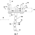
- Fig. 1 is a schematic view of an extension tool 100 in accordance with an exemplary embodiment of the present disclosure in a slacked position
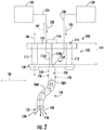
- Fig. 2 is a schematic view of the exemplary extension tool 100 of Fig. 1 in a tensioned position. Accordingly, it will be appreciated from the description herein that the extension tool 100 is a selectively flexible extension tool.
- the extension tool 100 generally includes a base 102, a line assembly 104, and a plurality of sequentially arranged links 106.
- the base 102 generally includes a first plate 108, a second plate 110, and one or more extension guides 112.
- the one or more extension guides 112 includes a pair of extension guides 112 fixedly coupled to the first plate 108 and extending in a lengthwise direction LW.
- the second plate 110 of the base 102 includes openings 114 corresponding to the pair of extension guides 112, such that the second plate 110 is slidable along the extension guides 112 in the lengthwise direction LW away from the first plate 108 and towards the first plate 108.
- the line assembly 104 generally includes a root 116 coupled to the second plate 110 of the base 102 and a plurality of lines 118 extending from the root 116.
- the plurality of lines 118 includes a first line 118A and second line 118B.
- the line assembly 104, and in particular the first and second lines 118A, 118B, are operable with the plurality of sequentially arranged links 106 to move the plurality of sequentially arranged links 106 between the slacked position ( Fig. 1 ) and the tensioned position ( Fig. 2 ).
- the plurality of sequentially arranged links 106 are spaced from one another when in the slacked position ( Fig. 1 ) to allow the plurality of sequentially arranged links 106 to pivotably move relative to one another.
- the plurality of sequentially arranged links 106 are pressed against one another when in the tensioned position ( Fig. 2 ) to rigidly fix the plurality of sequentially arranged links 106 to one another.
- each of the plurality of links 106 are designed to result in a specific rigidized shape when the plurality of links 106 are moved to the tensioned position.
- a first link 106A of the plurality of links 106 defines a first geometry (i.e., length, curvature, etc.) and a second link 106B of the plurality of links 106 defines a second geometry (i.e., link, curvature, etc.).
- the first geometry is different than the second geometry.
- each of the plurality of links 106 may be formed through an additive manufacturing process (sometimes also referred to as 3D printing). Such may facilitate the formation of specifically shaped links 106 to be fitted within the plurality of links 106 of an extension tool 100 resulting in a desired shape when moved to the tensioned position, yet still remaining flexible enough to fit through an anticipated environment.
- additive manufacturing process sometimes also referred to as 3D printing
- each of these lines 118 may be configured as cables, ropes, threads, etc. Accordingly, it will be appreciated that the lines 118 are generally flexible (i.e., will not significantly prevent the plurality of sequentially arranged links 106 from pivotably moving relative to one another in the slacked position). Further, one or more of the lines 118 may be formed of a metal material, such as a steel, tungsten, etc. Alternatively, however, the lines 118 may be formed of any other suitable material.
- the extension tool 100 depicted in Figs. 1 and 2 may include a tool implement coupled to one of the plurality of links 106.
- the extension tool 100 defines a distal end 122, and the tool implement may be coupled to the link 106 at the distal end 122.
- the tool implement may include one or more sensors, cameras, or both, and additionally, or alternatively, may include one or more drills, laser tools, welding implements, rotatable implements (such as a Phillips head screwdriver bit, a flat head screwdriver bit, a Torx bit, Allen bit, Pozidrive, or the like), etc.
- the extension tool 100 may facilitate performing mechanical operations on a part at a remote location, or along an obscure vector within an environment (e.g., along a non-linear path within the environment) that would otherwise be more difficult.
- the extension tool 100 may include a flexible driveshaft extending through an interior of the plurality of links 106, and more specifically, through a tube defined along a length of the plurality of links 106 (later described as a first passage).
- extension tool 100 may be configured in any other manner to perform operations at a remote location, or along an obscure vector, within an environment.
- the extension tool 100 is configured such that the plurality of sequentially arranged links 106 defines a passage therethrough when the plurality of sequentially arranged links 106 are in the tensioned position ( Fig. 2 ).
- the extension tool 100 is configured such that the plurality of sequentially arranged links 106 define a fluid flow passage therethrough when the plurality of sequentially arranged links 106 are in the tensioned position ( Fig. 2 ).
- the passage is a fluid flow passage.
- the passage may not be configured to provide a fluid flow and instead may be configured to, e.g., act as a guide tube for a tool.
- fluid flow passage refers to any substantially continuous passage through the plurality of sequentially arranged links 106 when the plurality of sequentially arranged links 106 are in the tensioned position, capable of providing a gas or liquid flow to a location proximate the distal end 122 of the plurality of sequentially arranged links 106, or extracting a gas or liquid flow from a location proximate the distal end 122 of the plurality of sequentially arranged links 106.
- the plurality of sequentially arranged links 106 together define a first passage and a second passage, the second passage being separate from the first passage when the plurality of sequentially arranged links 106 are in the tensioned position.
- the first passage is a first fluid flow passage 124 and the second passage is a second fluid flow passage 126.
- the first and/or second passage may not be configured to provide a fluid flow and instead may be configured to, e.g., act as a guide tube for a tool.
- the second fluid flow passage 126 is separate from the first fluid flow passage 124 when the plurality of sequentially arranged links 106 are in the tensioned position. In such a manner, separate fluids may flow through the respective first and second fluid flow passages 124, 126.
- the first fluid flow passage 124 is an inner fluid flow passage and the second fluid flow passage 126 is an outer fluid flow passage.
- the inner fluid flow passage is positioned inward of the outer fluid flow passage, with the outer fluid flow passage substantially completely surrounding the inner fluid flow passage.
- the outer fluid flow passage may define a generally annular shape surrounding the inner fluid flow passage.
- first and second fluid flow passages 124, 126 may be arranged in any other suitable manner.
- the first and second fluid flow passages 124, 126 may instead run parallel and adjacent to one another, but may not be arranged concentrically (e.g., one of the first or second fluid flow passages 124, 126 extending along one side of the plurality of links 106 and the other of the first or second fluid flow passages 124, 126 extending along another side of the plurality of links 106).
- the plurality of sequentially arranged links 106 may only define one passage extending therethrough, or may not define any passages extending therethrough.
- the extension tool 100 further includes features for providing one or more fluid flows through the first fluid flow passage 124, the second fluid flow passage 126, or both.
- the extension tool 100 further includes a first fluid flow device 128 fluidly coupled to the first fluid flow passage 124, the second fluid flow passage 126, or both.
- the first fluid flow device 128 is fluidly coupled to the first fluid flow passage 124 through a first conduit 130, and the extension tool 100 further includes a second fluid flow device 132 fluidly coupled to the second fluid flow passage 126 through a second conduit 134.
- the first fluid flow device 128 generally includes a first pressurized fluid source for providing a first pressurized fluid flow 136 (shown schematically through conduit 130) through the first fluid flow passage 124.
- the first pressurized fluid flow 136 may be, e.g., a heated gas flow, a pressurized gas flow, a heated liquid flow, a pressurized liquid flow, etc.
- the second fluid flow device 132 similarly includes a second pressurized fluid source for providing a second pressurized fluid flow 138 (shown schematically through conduit 134) through the second fluid flow passage 126.
- the second pressurized fluid 138 flow may include a different fluid flow than the first fluid flow 136 (e.g., a different gas, different liquid), may operate at a different temperature and/or pressure, etc.
- the first pressurized fluid flow 136 may be a heated gas flow operating at a first temperature (such as a first initial temperature as measured at a base end of the plurality of links 106) and the second pressurized fluid flow 138 may similarly be a heated gas flow operating at a second temperature (such as a second initial temperature as measured at a base end of the plurality of links 106).
- the second temperature may be less than the first temperature to reduce a thermal gradient on a component on which the first and second pressurized fluid flows 136, 138 are directed.
- the second temperature may be set to, e.g., ensure a thermal expansion of the first line 118A and the second line 118B of the line assembly 104 matches a thermal expansion of the plurality of links 106 during operation, thereby reducing a tension on the first and second lines 118A, 118B.
- the extension tool 100 may operate in any other suitable manner.
- the second pressurized fluid source of the second fluid flow device 132 may instead be a fluid pump for urging a second pressurized fluid flow 138' from the second fluid flow passage 126 in a direction opposite the first fluid flow 136.
- the extension tool 100 may, e.g., ensure any leakage of a first pressurized fluid flow 136 through the first fluid flow passage 124 (e.g., between adjacent links 106) is captured and not leaked into the environment, and/or, may operate to suction up excess of the first pressurized fluid flow 136 at the distal end 122 of the plurality of sequentially arranged links 106.
- the first pressurized fluid flow 136 may be a flow of oil or other lubrication being provided to a particular location within an environment, and the extension tool 100 may operate the second fluid flow passage 126 as a vacuum to suction up excess oil/lubrication at the particular location within the environment and further to capture any leakage from the first fluid flow passage 124.
- the extension tool 100 may not include separate fluid flow devices for the first and second fluid flow passages 124, 126.
- the first and second fluid flow passages 124, 126 may be fed from the same fluid flow source (e.g., the first fluid flow source 128).
- the fluid provided may be a heated fluid.
- the result may still be a first fluid flow 136 at the distal end 122 at a first temperature greater than a second temperature of a second fluid flow 138. Such may result from the second fluid flow effectively insulating the first fluid flow 136 and exchanging heat with the environment.
- the line assembly 104 is operable with the plurality of sequentially arranged links 106 to move the plurality of sequentially arranged links 106 between the slacked position ( Fig. 1 ) and tensioned position ( Fig. 2 ).
- the first line 118A and second line 118B of the line assembly 104 may be fixed to the link 106 at the distal end 122 of the plurality of sequentially arranged links 106.
- the tensioning force in the first line 118A and second line 118B presses each of the plurality of sequentially arranged links 106 against one another, fixing the plurality of sequentially arranged links 106 in position to form a substantially rigid extension.
- the plurality of links 106 includes a base link 140 fixed to the base 102, allowing the first and second lines 118A, 118B to be pulled tight.
- the first line 118A defines a first displacement when the plurality of sequentially arranged links 106 are moved from the slacked position to the tensioned position (i.e., the amount of slack taken out of the first line 118A), and similarly, the second line 118B defines a second displacement when the plurality of sequentially arranged links 106 are moved from the slacked position to the tensioned position (i.e., the amount of slack taken out of the second line 118B). More particularly, the first and second displacement may be measured by subtracting a first length 142 of the lines 118A, 118B between the plurality of links 106 and the root 116 ( Fig.
- first and second lines 118A and 118B may actually be first and second portions 119A, 119B of a continuous line 118, integral at the distal end 122.
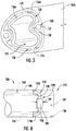
- Fig. 3 a schematic view of the distal end 122 of the plurality of sequentially arranged links 106 is depicted, with a portion of the link 106 at the distal end cut-away for clarity.
- the first line 118A is a first portion 119A of a line extending through the plurality of sequentially arranged links 106 to the link 106 at the distal end 122
- the second line 118B is a second portion 119B of a line 118 similarly extending through the plurality of sequentially arranged links 106 to the link 106 at the distal end 122
- the line further includes a transition portion 119C extending between the first and second portions 119A, 119B of the line 118 at the link 106 at the distal end 122. In such a manner, the line 118 loops around at the link 106 at the distal end 122.
- the extension tool 100 further includes attachment feature 190 coupled to or formed integrally with the line 118 of the line assembly 104 at the transition portion 119C of the line 118 to allow for the line 118 to support the links 106 in the event of a failure of the line 118.
- Fig. 4 depicts a close-up view of a junction between adjacent links 106 of the plurality of links 106 of the extension tool 100 depicted above in Figs. 1 and 2
- Fig. 5 provides a close-up view of one end of one of the links 106 of Fig. 4 .
- a first link 106A in the plurality of sequentially arranged links 106 includes a wall 156. More specifically, for the embodiment shown, the first link 106A in the plurality of sequentially arranged links 106 includes a first wall 156A and a second wall 156B. The first wall 156A of the first link 106A defines in part the first fluid flow passage 124 and the second wall 156B of the first link 106A defines in part the second fluid flow passage 126.
- the first wall 156A is an inner wall and the second wall 156B is an outer wall. The outer wall substantially completely surrounds the inner wall 156, such that the second fluid flow passage 126 is a generally annular passage surrounding the first fluid flow passage 124.
- the second wall 156B is coupled to the first wall 156A through one or more point contacts 174 (see Fig. 5 ), such that the first and second wall 156A, 156B are not continuously connected along a length of each respective link 106.
- the one or more point contacts 174 are located at the ends of the links 106 (e.g., as first and second ends of each link 106).
- the term "point contact" with reference to the connection between the first and second wall 156A, 156B of a respective link 106 refers to a connection that does not extend significantly along a length of the respective link, such as less than about 25% along a length of a respective link 106.
- the point contacts 174 may extend less than about 15% along a length of a respective link 106, such as less than about 10% along a length of a respective link 106, such as less than about 5% along a length of a respective link 106.
- This embodiment represents an innovative solution to limit a thermal conduction path from outer wall 156B to inner wall 156A by providing a narrow connection element (i.e., point contacts 174).
- first wall 156A may be coupled to the second wall 156B in any suitable manner.
- the plurality of links 106 may include any other suitable number of walls.
- the plurality of sequentially arranged links 106 include a plurality of line guides for the one or more of lines 118 of the line assembly 104.
- the line assembly 104 includes the first line 118A and the second line 118B
- the plurality of sequentially arranged links 106 similarly includes a first line guide 160 and a second line guide 164.
- Each link 106 includes a segment 158 of the first line guide 160 and segment 162 of the second line guide 164.
- the line guides 160, 164 are positioned on an interior of the second wall 156B of each link 106 of the plurality of links 106.
- the line guides may instead be located elsewhere, such as on an outside of the second wall 156B, on an outside of the first wall 156A, on an interior of the first wall 156A, or some combination thereof.
- first and second line guides 160, 164 define a width 157 (i.e., a minimum cross-wise measure; see Fig. 5 ).
- the portions 119A, 119B, 119C of the line 118 of the line assembly 104 each define a width 121 (see Fig. 4 ).
- the width 157 of the first and second line guides 160, 164 is slightly larger than the width 121 of the portions 119A, 119B, 119C of the line 118 of the line assembly 104 to accommodate some movement of the line 118 during operation of the extension tool 100, while still providing some constraint of the line 118.
- adjacent links 106 are sealed together by including mating geometries at their respective ends that are complementary in shape with the mating geometries of the adjacent links.
- the walls 156 of the links 106 are pressed together and the contact pressure applied by the lines 118 may form a contact seal therebetween to provide a seal between such links 106.
- a close-up, schematic view of a link 106 of a plurality of links 106 of an extension tool 100 is provided at a distal end 122 of the plurality of links 106 in accordance with an exemplary embodiment of the present disclosure.
- the link 106 may accordingly be referred to as a distal link 106, and may be configured in accordance with one or more of the exemplary embodiments described above, or alternatively may be configured in accordance with any other suitable embodiment.
- the extension tool 100 includes a line 118 extending along a length thereof.
- the line 118 is configured as a single line 118 looped at the distal end 122.
- the line 118 includes a first portion 119A that is the first line 118A, a second portion 119B that is the second line 118B, a transition portion 119C at the distal end 122 extending between the first and second portions 119A, 119B of the line 118.
- the first portion 119A extends through the plurality of sequentially arranged links 106 to the distal link 106
- the second portion 119B similarly extends through the plurality of sequentially arranged links 106 to the distal link 106.
- the extension tool 100 includes an attachment feature 190 coupled to or formed integrally with the line 118 of the line assembly 104 at the transition portion 119C of the line 118 to support the line 118 in the event of a failure of the line 118. More specifically, the attachment feature 190 supports the line 118 in the event of a failure of the first portion 119A or the second portion 119B of the line 118.
- the attachment feature 190 prevents the other portion of the line 118 from sliding through the line guides in the links 106, allowing the links 106 to scatter and fall apart within the environment.
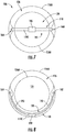
- the plurality of sequentially arranged links 106 defines a passage extending along a length thereof. More particularly, the plurality of sequentially arranged links 106 defines a first fluid flow passage 124 and a second fluid flow passage 126. Further, the distal link 106 defines a line path 191 along which the line 118 extends from the first line guide 160 to the second line guide 164.
- the line path 191 extends through the passage defined by the plurality of sequentially arranged links 106, and more specifically extends through the first fluid flow passage 124 and through the second fluid flow passage 126. Additionally, for the embodiment of Fig. 7 , the attachment feature 190 is positioned within the first fluid flow passage 124. Such a configuration may ensure the attachment feature 190 is not under significant tension during normal operations.
- the line path 191 may extend in any suitable manner.
- the line path 191 extends around the passage defined by the plurality of sequentially arranged links 106, and more specifically extends around the first fluid flow passage 124 and around the second fluid flow passage 126.
- the distal link 106 includes a transition portion guide 193 along the second wall 156B such that the transition portion 119C of the line 118 and attachment feature 190 are isolated from a fluid flow within the first and second fluid flow passages 124, 126. Such may assist with maintaining an integrity of the line 118 and attachment feature 190 when a fluid flow through these passages may otherwise degrade the line 118 and/or attachment feature 190. Such may also reduce an impediment on the fluid flow through these passages.
- the attachment feature 190 defines a greater width 189 than the width 121 of the first and second lines 118A, 118B (see Fig. 4 ), and greater than the width 157 of the first and second line guides 160, 164 (see Fig. 5 ). In such a manner, the attachment feature 190 may prevent the first portion 119A or second portion 119B of the line 118 from pulling out through the respective first or second line guide 160, 164 in the event of a failure of the other of the first or second portion 119A, 119B of the line 118.
- the attachment feature 190 may not be under any significant load during normal operations.
- the line 118, and more particularly, the first and second portions 119A, 119B of the line 118 may be exposed to a maximum load during normal operations.
- the maximum load during normal operations refers to a maximum tension load during all rated operations of the extension tool 100.
- the attachment feature 190 may also be exposed to a maximum load during normal operations.
- the maximum load on the attachment feature 190 may be below twenty-five percent of the maximum load on the line 118 of the line assembly 104 during normal operation of the extension tool 100.
- the maximum load on the attachment feature 190 may be below fifteen percent of the maximum load on the line 118 of the line assembly 104 during normal operation of the extension tool 100, such as below ten percent of the maximum load on the line 118 of the line assembly 104 during normal operation of the extension tool 100, such as below five percent of the maximum load on the line 118 of the line assembly 104 during normal operation of the extension tool 100.
- the link 106 at the distal end includes support surfaces 198 to support the transition portion 119C of the line 118 as it extends between the first and second portions 119A, 119B, such that a load on the attachment feature 190 may be minimized.
- the attachment feature 190 may effectively float between the support surfaces 198.
- the attachment feature 190 may be configured to abut against a respective line guide 160, 164 to prevent the portion of the line 118 remaining intact from sliding therethrough, allowing for the portion of the line 118 remaining intact to be used to remove the plurality of links 106 from the environment.
- the distal link 106 may have any other suitable configuration.
- Fig. 9 another close-up, schematic view of a link 106 of a plurality of links 106 of an extension tool 100 is provided at a distal end 122 of the plurality of links 106 in accordance with an exemplary embodiment of the present disclosure.
- the link 106 depicted in Fig. 9 may be configured in a similar manner to the exemplary link 106 described above with respect to Fig. 6 .
- the exemplary extension tool 100 depicted includes a plurality of sequentially arranged links 106 and a line assembly 104 having a line 118.
- the line 118 includes a first portion 119A extending through the plurality of sequentially arranged links to the distal link 106, a second portion 119B extending through the plurality of sequentially arranged links to the distal link 106, and a transition portion 119C extending between the first and second portions 119A, 119B.
- the extension tool 100 further includes an attachment feature 190 fixedly coupled to the line 118 at the transition portion 119C of the line 118.
- the link 106 at the distal end 122 further defines an opening 192, with the transition portion 119C of the line 118 extending across the opening 192 and the attachment feature 190 located within the opening 192.
- the opening 192 defines a first shoulder 194 where the transition portion 119C of the line 118 enters across the opening 192 and a second shoulder 196 where the transition portion 119C of the line 118 exits across the opening 192.
- the attachment feature 190 is positioned between the first and second shoulders 194, 196, without touching the first and second shoulders 194, 196 during normal operation.
- the load on the attachment feature 190 may be minimized.
- the attachment feature 190 may abut against the first shoulder 194 or the second shoulder 196 to prevent the portion of the line 118 remaining intact from sliding through the respective line guides 160, 164, allowing for the portion of the line 118 remaining intact to be used to remove the plurality of links 106 from the environment.
- the attachment feature 190 is fixedly coupled to the transition portion 119C of the lines 118.
- various embodiments of a line and attachment feature 190 are depicted.
- the lines 118 and attachment features 190 depicted in these Figs. may be incorporated into one or more of the exemplary embodiments described above.
- Figs. 10 through 13 depict various embodiments of an attachment feature 190 fixed to a line 118.
- the attachment feature 190 is a casing 195 fixed to the transition portion 119C of the line 118.
- the casing 195 extends around a section of the transition portion 119C of the line 118 and for the embodiment depicted is crimped onto the transition portion 119C of the line 118 (as is indicated by the crimp indentations in the casing 195).
- the casing 195 may define a "C" shape allowing for the change in internal diameter when it is fixed to the transition portion 119C (and therefore defining a gap 187).
- the casing 195 may define an annular shape.
- two crimp indentations are shown in Fig. 10 spaced along a longitudinal direction, in other embodiments one or more longitudinal crimps may be provided, extending along all or a portion of a length of the casing 195.
- the attachment feature 190 again includes a casing 195 fixed to the transition portion 119C of the line 118.
- the casing 195 is coupled to the transition portion 119C of the line 118 using a mechanical fastener 197. More specifically, the casing 195 is coupled to the transition portion 119C of the line 118 using screw or bolt extending through the casing 195 and pressing onto the line 118.
- the attachment feature 190 again includes a casing 195 fixed to the transition portion 119C of the line 118.
- the casing 195 is coupled to the transition portion 119C of the line 118 through welding, soldering, adhesive bonding, or a combination thereof.
- the casing 195 is coupled to the transition portion 119C of the line 118 through welding (as is indicated by the weld bead 199 depicted).
- the attachment feature 190 again includes a casing 195 fixed to the transition portion 119C of the line 118.
- the casing 195 is formed onto the transition portion 119C of the line 118.
- the casing 195 may be cast as a molten metal into a mold temporarily fixed around the line 118.
- the casing 195 may be permanently fixed around the line 118 as, e.g., a "Spelter socket" or the like.
- attachment feature 190 may be coupled to the line 118 in any other suitable manner.
- Fig. 14 depicts an extension tool 100 in accordance with an exemplary embodiment of the present disclosure being utilized to navigate through a nonlinear path within an environment, which for the embodiment shown is a gas turbine engine 200.
- the gas turbine engine 200 is configured as a turbofan engine.
- the turbofan engine generally includes a fan section 204 and a turbomachine 206.
- the turbomachine 206 generally includes a compressor section having a low pressure (“LP") compressor 208 and a high pressure (“HP") compressor 210; a combustion section 212; a turbine section including an HP turbine 214 and an LP turbine 216; and an exhaust section (not shown).
- the compressor section, combustion section 212, turbine section, and exhaust section are each arranged in serial flow order.
- the LP compressor 208 and LP turbine 216 are coupled through an LP shaft 218, and similarly, the HP compressor 210 and HP turbine 214 are coupled to an HP shaft 220.
- the turbomachine 26 includes a casing 221 enclosing at least in part the above-noted components of the turbomachine 206.
- the fan section 204 includes a fan having a plurality of fan blades 222, with the fan and plurality of fan blades 222 being driven by the LP shaft 218.
- the combustion section 212 generally includes an inner liner 224 and an outer liner 226, together defining at least in part a combustion chamber 228.
- the combustion section 212 further includes a fuel nozzle 230 configured to provide, e.g., a mixture of fuel and compressed air to be combusted within the combustion chamber 228 during operation of the gas turbine engine 200.
- An igniter (not shown) may be positioned within an igniter hole 232 of the outer liner 226 for igniting the fuel and compressed air mixture.
- an undesirable amount of coke buildup may form on or within the fuel nozzle 230.
- fuel may remain within the fuel nozzle 230 and residual heat within the gas turbine engine 200 may cause the remaining fuel to coke.
- the extension tool 100 may be utilized to remove the buildup of coke on or within the fuel nozzle 230.
- the exemplary extension tool 100 depicted may be configured in accordance with one or more of the exemplary embodiments described above with reference to Figs. 1 through 12 .
- the exemplary extension tool may generally include a plurality of links 106 movable to a tensioned position (shown) having a nonlinear, two-dimensional or three-dimensional shape when in the tensioned position.
- the ability to additionally be moved to a slacked position may assist with moving the plurality of links 106 through the gas turbine engine 200 environment and through the igniter hole 232.
- the plurality of links 106 may together define a first fluid flow passage 124 (not shown) and a second fluid flow passage 126 (not shown).
- the extension tool 100 may be configured to provide a first gas flow 136 through the first fluid flow passage 124 and a second gas flow 138 through the second fluid flow passage 126.
- the first gas flow 136 may be a heated and pressurized gas flow defining a first operational temperature
- the second gas flow 138 may also be a heated and pressurized gas flow defining a second operational temperature.
- the first operational temperature may be sufficient to burn off the coke within the fuel nozzle 230.
- the second operational temperature may be less than the first operational temperature for heating to a lesser degree the area surrounding the coke buildup being burnt off to lessen a temperature gradient across the component.
- the extension tool 100 may be utilized for a myriad of different operations and functions, and further may have any other suitable configuration.
- the extension tool 100 may not define two fluid flow passages, or any fluid flow passages.
- the embodiments depicted show the extension tool 100 having a line assembly 104 with a single line 118 extending down and back along an entire length of the plurality of links 106 (i.e., including the first and second portions 119A, 119B), in other embodiments, the line assembly 104 may include any suitable number of lines 118 configured in any suitable manner.
- the line assembly 104 may include at least two lines 118, with each extending down and back along an entire length of the plurality of links 106.
- one or more of the lines may not extend down and back along an entire length of the plurality of links 106, and may instead loop back at an intermediate location.
- the line assembly 104 may include a line 118 that extends one way along a length of the plurality of links 106. This single line 118 may be anchored at the distal end 122 to a link 106, and may similarly include an attachment feature 190 as a secondary retention feature in the event the anchor breaks or there is some other failure.
- the extension tool may generally include a plurality of sequentially arranged links, a line assembly having a line extending along a length of the plurality of sequentially arranged links, and an attachment feature coupled to or formed integrally with the line of the line assembly.
- the method 300 includes at (302) moving plurality of sequentially arranged links between a tensioned position and a slacked position at least in part with the line of the line assembly while maintaining a maximum load on the attachment feature below twenty-five percent of a maximum load on the line of the line assembly.
- moving the plurality of sequentially arranged links between the tensioned position and the slacked position at (302) includes at (304) maintaining the attachment feature within an opening of a first link located at a distal end of the plurality of sequentially arranged links.
- moving the plurality of sequentially arranged links between the tensioned position and the slacked position at (302) includes at (306) moving the plurality of sequentially arranged links to the tensioned position by applying the maximum load on the line of the line assembly in a tensioning direction.
Landscapes
- Engineering & Computer Science (AREA)
- Robotics (AREA)
- Mechanical Engineering (AREA)
- Surgical Instruments (AREA)
- Endoscopes (AREA)
Abstract
Description
- The present subject matter relates generally to a line assembly for an extension tool having a plurality of links.
- Robotic arm assemblies are useful throughout various industries for performing operations at, e.g., remote locations, hazardous locations, etc. At least certain robotic arm assemblies include a robotic arm formed of a plurality of links joined together at respective joints. Additionally, a plurality of control wires may extend through the robotic arm, with each wire terminating at an individual link for moving such link relative to an aft-adjacent link. The control wires may be coupled to one or more motors within a base of the robotic arm assembly, such that the robotic arm assembly may control a movement of the robotic arm by increasing and/or decreasing tension on the plurality of control wires.
- In such a manner, robotic arms may be useful in reaching out-of-sight locations within various environments. However, robotic arms may generally be cost prohibitive and/or more complicated than desired for certain applications. Accordingly, a tool that may allow for a user to reach remote locations within an environment in a more cost efficient manner would be useful.
- Aspects and advantages of the invention will be set forth in part in the following description, or may be obvious from the description, or may be learned through practice of the invention.
- In one exemplary embodiment of the present disclosure, an extension tool is provided including a plurality of sequentially arranged links moveable relative to one another. The plurality of sequentially arranged links include a first link. The extension tool further includes a line assembly having a line, the line including a first portion extending through the plurality of sequentially arranged links to the first link and a transition portion extending from the first portion through the first link. The extension tool further includes an attachment feature coupled to or formed integrally with the line of the line assembly at the transition portion of the line to support the line in the event of a failure of the line.
- These and other features, aspects and advantages of the present invention will become better understood with reference to the following description and appended claims. The accompanying drawings, which are incorporated in and constitute a part of this specification, illustrate embodiments of the invention and, together with the description, serve to explain the principles of the invention.
- A full and enabling disclosure of the present invention, including the best mode thereof, directed to one of ordinary skill in the art, is set forth in the specification, which makes reference to the appended Figs., in which:
-
Fig. 1 is a schematic view of an extension tool in accordance with an exemplary embodiment of the present disclosure in a slacked position. -
Fig. 2 is a schematic view of the exemplary extension tool ofFig. 1 in a tensioned position. -
Fig. 3 is a schematic, cross sectional view of a distal end of the exemplary extension tool ofFig. 1 . -
Fig. 4 is a close-up view of a junction between adjacent links of an extension tool in accordance with an exemplary embodiment of the present disclosure in a slacked position. -
Fig. 5 is a close-up view of one end of one of the links ofFig. 4 . -
Fig. 6 is a close-up, schematic view of a link which may be part of a plurality of links of an extension tool in accordance with an exemplary embodiment of the present disclosure. -
Fig. 7 is a schematic view of a downstream end of a link of a plurality of links of an extension tool in accordance with an exemplary embodiment of the present disclosure. -
Fig. 8 is a schematic view of a downstream end of a link of a plurality of links of an extension tool in accordance with another exemplary embodiment of the present disclosure. -
Fig. 9 is a close-up, schematic view of a link which may be part of a plurality of links of an extension tool in accordance with another exemplary embodiment of the present disclosure. -
Fig. 10 is a schematic view of an attachment feature coupled to a line in accordance with an embodiment of the present disclosure. -
Fig. 11 is a schematic view of an attachment feature coupled to a line in accordance with another embodiment of the present disclosure. -
Fig. 12 is a schematic view of an attachment feature coupled to a line in accordance with yet another embodiment of the present disclosure. -
Fig. 13 is a schematic view of an attachment feature coupled to a line in accordance with still another embodiment of the present disclosure. -
Fig. 14 is a schematic view of a gas turbine engine and extension tool in accordance with an exemplary embodiment of the present disclosure. -
Fig. 15 is a flow diagram of a method for operating an extension tool in accordance with an exemplary aspect of the present disclosure. - Reference will now be made in detail to present embodiments of the invention, one or more examples of which are illustrated in the accompanying drawings. The detailed description uses numerical and letter designations to refer to features in the drawings. Like or similar designations in the drawings and description have been used to refer to like or similar parts of the invention.
- As used herein, the terms "first", "second", and "third" may be used interchangeably to distinguish one component from another and are not intended to signify location or importance of the individual components.
- The terms "forward" and "aft" refer to relative positions of a component or system, and refer to the normal operational attitude of the component or system. For example, with regard to an extension tool in accordance with one or more the present embodiments, forward refers to a position closer to a distal end of the extension tool and aft refers to a position closer to a root end of the extension tool.
- The terms "coupled," "fixed," "attached to," and the like refer to both direct coupling, fixing, or attaching, as well as indirect coupling, fixing, or attaching through one or more intermediate components or features, unless otherwise specified herein.
- The singular forms "a", "an", and "the" include plural references unless the context clearly dictates otherwise.
- Approximating language, as used herein throughout the specification and claims, is applied to modify any quantitative representation that could permissibly vary without resulting in a change in the basic function to which it is related. Accordingly, a value modified by a term or terms, such as "about", "approximately", and "substantially", are not to be limited to the precise value specified. In at least some instances, the approximating language may correspond to the precision of an instrument for measuring the value, or the precision of the methods or machines for constructing or manufacturing the components and/or systems. For example, the approximating language may refer to being within a 10 percent margin.
- Here and throughout the specification and claims, range limitations are combined and interchanged, such ranges are identified and include all the sub-ranges contained therein unless context or language indicates otherwise. For example, all ranges disclosed herein are inclusive of the endpoints, and the endpoints are independently combinable with each other.
- Referring now to the drawings, wherein identical numerals indicate the same elements throughout the Figs.,
Fig. 1 is a schematic view of anextension tool 100 in accordance with an exemplary embodiment of the present disclosure in a slacked position; andFig. 2 is a schematic view of theexemplary extension tool 100 ofFig. 1 in a tensioned position. Accordingly, it will be appreciated from the description herein that theextension tool 100 is a selectively flexible extension tool. - The
extension tool 100 generally includes abase 102, aline assembly 104, and a plurality of sequentially arrangedlinks 106. Thebase 102 generally includes afirst plate 108, asecond plate 110, and one ormore extension guides 112. For the embodiment depicted, the one ormore extension guides 112 includes a pair ofextension guides 112 fixedly coupled to thefirst plate 108 and extending in a lengthwise direction LW. Thesecond plate 110 of thebase 102 includesopenings 114 corresponding to the pair ofextension guides 112, such that thesecond plate 110 is slidable along theextension guides 112 in the lengthwise direction LW away from thefirst plate 108 and towards thefirst plate 108. - The
line assembly 104 generally includes aroot 116 coupled to thesecond plate 110 of thebase 102 and a plurality oflines 118 extending from theroot 116. The plurality oflines 118 includes afirst line 118A andsecond line 118B. As will be appreciated from the discussion herein below, theline assembly 104, and in particular the first andsecond lines links 106 to move the plurality of sequentially arrangedlinks 106 between the slacked position (Fig. 1 ) and the tensioned position (Fig. 2 ). Further, it will be appreciated that for the embodiment depicted, although the lines are depicted as being spaced from one another in a crosswise direction CW in the embodiment depicted for explanatory purposes, in at least certain embodiments they may be aligned with one another in the crosswise direction CW. - As will be explained in greater detail below, the plurality of sequentially arranged
links 106 are spaced from one another when in the slacked position (Fig. 1 ) to allow the plurality of sequentially arrangedlinks 106 to pivotably move relative to one another. By contrast, the plurality of sequentially arrangedlinks 106 are pressed against one another when in the tensioned position (Fig. 2 ) to rigidly fix the plurality of sequentially arrangedlinks 106 to one another. - For the embodiment of
Figs. 1 and2 , it will be appreciated that each of the plurality oflinks 106 are designed to result in a specific rigidized shape when the plurality oflinks 106 are moved to the tensioned position. For example, afirst link 106A of the plurality oflinks 106 defines a first geometry (i.e., length, curvature, etc.) and asecond link 106B of the plurality oflinks 106 defines a second geometry (i.e., link, curvature, etc.). The first geometry is different than the second geometry. In at least certain exemplary embodiments, in order to form the plurality oflinks 106 having specific geometries to facilitate a desired shape of the plurality oflinks 106, each of the plurality oflinks 106 may be formed through an additive manufacturing process (sometimes also referred to as 3D printing). Such may facilitate the formation of specifically shapedlinks 106 to be fitted within the plurality oflinks 106 of anextension tool 100 resulting in a desired shape when moved to the tensioned position, yet still remaining flexible enough to fit through an anticipated environment. - Further, with regard to the plurality of
lines 118 of theline assembly 104, it will be appreciated that each of theselines 118 may be configured as cables, ropes, threads, etc. Accordingly, it will be appreciated that thelines 118 are generally flexible (i.e., will not significantly prevent the plurality of sequentially arrangedlinks 106 from pivotably moving relative to one another in the slacked position). Further, one or more of thelines 118 may be formed of a metal material, such as a steel, tungsten, etc. Alternatively, however, thelines 118 may be formed of any other suitable material. - In at least certain exemplary embodiments, it will be appreciated that the
extension tool 100 depicted inFigs. 1 and2 may include a tool implement coupled to one of the plurality oflinks 106. For example, theextension tool 100 defines adistal end 122, and the tool implement may be coupled to thelink 106 at thedistal end 122. In certain exemplary embodiments, the tool implement may include one or more sensors, cameras, or both, and additionally, or alternatively, may include one or more drills, laser tools, welding implements, rotatable implements (such as a Phillips head screwdriver bit, a flat head screwdriver bit, a Torx bit, Allen bit, Pozidrive, or the like), etc. In such a manner, theextension tool 100 may facilitate performing mechanical operations on a part at a remote location, or along an obscure vector within an environment (e.g., along a non-linear path within the environment) that would otherwise be more difficult. - With one or more of the configurations, the
extension tool 100 may include a flexible driveshaft extending through an interior of the plurality oflinks 106, and more specifically, through a tube defined along a length of the plurality of links 106 (later described as a first passage). - It will further be appreciated, however, that in other embodiments, the
extension tool 100 may be configured in any other manner to perform operations at a remote location, or along an obscure vector, within an environment. - Specifically, for the embodiment shown, the
extension tool 100 is configured such that the plurality of sequentially arrangedlinks 106 defines a passage therethrough when the plurality of sequentially arrangedlinks 106 are in the tensioned position (Fig. 2 ). - More specifically, for the embodiment shown, the
extension tool 100 is configured such that the plurality of sequentially arrangedlinks 106 define a fluid flow passage therethrough when the plurality of sequentially arrangedlinks 106 are in the tensioned position (Fig. 2 ). For the embodiment depicted, the passage is a fluid flow passage. However, in other embodiments, the passage may not be configured to provide a fluid flow and instead may be configured to, e.g., act as a guide tube for a tool. - It will be appreciated, that as used herein, the term "fluid flow passage" refers to any substantially continuous passage through the plurality of sequentially arranged
links 106 when the plurality of sequentially arrangedlinks 106 are in the tensioned position, capable of providing a gas or liquid flow to a location proximate thedistal end 122 of the plurality of sequentially arrangedlinks 106, or extracting a gas or liquid flow from a location proximate thedistal end 122 of the plurality of sequentially arrangedlinks 106. - More specifically, referring particular to
Fig. 2 , the plurality of sequentially arrangedlinks 106 together define a first passage and a second passage, the second passage being separate from the first passage when the plurality of sequentially arrangedlinks 106 are in the tensioned position. More specifically, still, for the embodiment shown, the first passage is a firstfluid flow passage 124 and the second passage is a secondfluid flow passage 126. However, as noted above, in other embodiments the first and/or second passage may not be configured to provide a fluid flow and instead may be configured to, e.g., act as a guide tube for a tool. - The second
fluid flow passage 126 is separate from the firstfluid flow passage 124 when the plurality of sequentially arrangedlinks 106 are in the tensioned position. In such a manner, separate fluids may flow through the respective first and secondfluid flow passages Fig. 2 , the firstfluid flow passage 124 is an inner fluid flow passage and the secondfluid flow passage 126 is an outer fluid flow passage. In such a manner, the inner fluid flow passage is positioned inward of the outer fluid flow passage, with the outer fluid flow passage substantially completely surrounding the inner fluid flow passage. As such, the outer fluid flow passage may define a generally annular shape surrounding the inner fluid flow passage. - However, in other exemplary embodiments, the first and second
fluid flow passages fluid flow passages fluid flow passages links 106 and the other of the first or secondfluid flow passages - Additionally, in still other embodiments, the plurality of sequentially arranged
links 106 may only define one passage extending therethrough, or may not define any passages extending therethrough. - Referring still particularly to
Fig. 2 , it will be appreciated that theextension tool 100 further includes features for providing one or more fluid flows through the firstfluid flow passage 124, the secondfluid flow passage 126, or both. For example, for the embodiment ofFig. 2 , theextension tool 100 further includes a firstfluid flow device 128 fluidly coupled to the firstfluid flow passage 124, the secondfluid flow passage 126, or both. - In particular, for the embodiment of
Fig. 2 the firstfluid flow device 128 is fluidly coupled to the firstfluid flow passage 124 through afirst conduit 130, and theextension tool 100 further includes a secondfluid flow device 132 fluidly coupled to the secondfluid flow passage 126 through asecond conduit 134. In certain embodiments, such as the embodiment shown, the firstfluid flow device 128 generally includes a first pressurized fluid source for providing a first pressurized fluid flow 136 (shown schematically through conduit 130) through the firstfluid flow passage 124. The firstpressurized fluid flow 136 may be, e.g., a heated gas flow, a pressurized gas flow, a heated liquid flow, a pressurized liquid flow, etc. - Further for the embodiment of
Fig. 2 , the secondfluid flow device 132 similarly includes a second pressurized fluid source for providing a second pressurized fluid flow 138 (shown schematically through conduit 134) through the secondfluid flow passage 126. The secondpressurized fluid 138 flow may include a different fluid flow than the first fluid flow 136 (e.g., a different gas, different liquid), may operate at a different temperature and/or pressure, etc. - For example, in certain exemplary embodiments the first
pressurized fluid flow 136 may be a heated gas flow operating at a first temperature (such as a first initial temperature as measured at a base end of the plurality of links 106) and the secondpressurized fluid flow 138 may similarly be a heated gas flow operating at a second temperature (such as a second initial temperature as measured at a base end of the plurality of links 106). The second temperature may be less than the first temperature to reduce a thermal gradient on a component on which the first and second pressurized fluid flows 136, 138 are directed. Additionally, or alternatively, the second temperature may be set to, e.g., ensure a thermal expansion of thefirst line 118A and thesecond line 118B of theline assembly 104 matches a thermal expansion of the plurality oflinks 106 during operation, thereby reducing a tension on the first andsecond lines - It will be appreciated, however, that in other exemplary embodiments, the
extension tool 100 may operate in any other suitable manner. For example, as is depicted in phantom inFig. 2 , and other exemplary embodiments, the second pressurized fluid source of the secondfluid flow device 132 may instead be a fluid pump for urging a second pressurized fluid flow 138' from the secondfluid flow passage 126 in a direction opposite thefirst fluid flow 136. With such a configuration, theextension tool 100 may, e.g., ensure any leakage of a firstpressurized fluid flow 136 through the first fluid flow passage 124 (e.g., between adjacent links 106) is captured and not leaked into the environment, and/or, may operate to suction up excess of the firstpressurized fluid flow 136 at thedistal end 122 of the plurality of sequentially arrangedlinks 106. For example, the firstpressurized fluid flow 136 may be a flow of oil or other lubrication being provided to a particular location within an environment, and theextension tool 100 may operate the secondfluid flow passage 126 as a vacuum to suction up excess oil/lubrication at the particular location within the environment and further to capture any leakage from the firstfluid flow passage 124. - Additionally, or alternatively, the
extension tool 100 may not include separate fluid flow devices for the first and secondfluid flow passages fluid flow passages first fluid flow 136 at thedistal end 122 at a first temperature greater than a second temperature of asecond fluid flow 138. Such may result from the second fluid flow effectively insulating thefirst fluid flow 136 and exchanging heat with the environment. - Referring again to both
Figs. 1 and2 , it will be appreciated that theline assembly 104 is operable with the plurality of sequentially arrangedlinks 106 to move the plurality of sequentially arrangedlinks 106 between the slacked position (Fig. 1 ) and tensioned position (Fig. 2 ). Specifically, thefirst line 118A andsecond line 118B of theline assembly 104 may be fixed to thelink 106 at thedistal end 122 of the plurality of sequentially arrangedlinks 106. When thefirst line 118A andsecond line 118B of theline assembly 104 are tensioned by applying a tensioning force to thelines second lines first line 118A andsecond line 118B presses each of the plurality of sequentially arrangedlinks 106 against one another, fixing the plurality of sequentially arrangedlinks 106 in position to form a substantially rigid extension. Notably, for the embodiment show, the plurality oflinks 106 includes abase link 140 fixed to thebase 102, allowing the first andsecond lines - Briefly, it will also be appreciated that the
first line 118A defines a first displacement when the plurality of sequentially arrangedlinks 106 are moved from the slacked position to the tensioned position (i.e., the amount of slack taken out of thefirst line 118A), and similarly, thesecond line 118B defines a second displacement when the plurality of sequentially arrangedlinks 106 are moved from the slacked position to the tensioned position (i.e., the amount of slack taken out of thesecond line 118B). More particularly, the first and second displacement may be measured by subtracting afirst length 142 of thelines links 106 and the root 116 (Fig. 1 ) when thelinks 106 are in the slacked position from asecond length 144 of thelines links 106 and the root 116 (Fig. 2 ) when thelinks 106 are in the tensioned position. - Notably, as will be appreciated from the discussion hereinbelow, in at least certain exemplary embodiments, the first and
second lines second portions continuous line 118, integral at thedistal end 122. For example, referring now briefly toFig. 3 , a schematic view of thedistal end 122 of the plurality of sequentially arrangedlinks 106 is depicted, with a portion of thelink 106 at the distal end cut-away for clarity. As shown, thefirst line 118A is afirst portion 119A of a line extending through the plurality of sequentially arrangedlinks 106 to thelink 106 at thedistal end 122, and thesecond line 118B is asecond portion 119B of aline 118 similarly extending through the plurality of sequentially arrangedlinks 106 to thelink 106 at thedistal end 122. The line further includes atransition portion 119C extending between the first andsecond portions line 118 at thelink 106 at thedistal end 122. In such a manner, theline 118 loops around at thelink 106 at thedistal end 122. Such may allow for theline 118 to provide the tensioning force to move thelinks 106 to the tensioned position (Fig. 2 ). As will be discussed in more detail below, theextension tool 100 further includesattachment feature 190 coupled to or formed integrally with theline 118 of theline assembly 104 at thetransition portion 119C of theline 118 to allow for theline 118 to support thelinks 106 in the event of a failure of theline 118. - Referring now to
Figs. 4 and5 , exemplary aspects of theextension tool 100 described above with respect toFigs. 1 and2 are depicted.Fig. 4 depicts a close-up view of a junction betweenadjacent links 106 of the plurality oflinks 106 of theextension tool 100 depicted above inFigs. 1 and2 , andFig. 5 provides a close-up view of one end of one of thelinks 106 ofFig. 4 . - As shown, a
first link 106A in the plurality of sequentially arrangedlinks 106 includes a wall 156. More specifically, for the embodiment shown, thefirst link 106A in the plurality of sequentially arrangedlinks 106 includes afirst wall 156A and asecond wall 156B. Thefirst wall 156A of thefirst link 106A defines in part the firstfluid flow passage 124 and thesecond wall 156B of thefirst link 106A defines in part the secondfluid flow passage 126. For the embodiment shown, thefirst wall 156A is an inner wall and thesecond wall 156B is an outer wall. The outer wall substantially completely surrounds the inner wall 156, such that the secondfluid flow passage 126 is a generally annular passage surrounding the firstfluid flow passage 124. - For the embodiment depicted, the
second wall 156B is coupled to thefirst wall 156A through one or more point contacts 174 (seeFig. 5 ), such that the first andsecond wall respective link 106. Specifically, for the embodiment shown, the one ormore point contacts 174 are located at the ends of the links 106 (e.g., as first and second ends of each link 106). It will be appreciated that as used herein, the term "point contact" with reference to the connection between the first andsecond wall respective link 106 refers to a connection that does not extend significantly along a length of the respective link, such as less than about 25% along a length of arespective link 106. For example, in certain exemplary embodiments, thepoint contacts 174 may extend less than about 15% along a length of arespective link 106, such as less than about 10% along a length of arespective link 106, such as less than about 5% along a length of arespective link 106. This embodiment represents an innovative solution to limit a thermal conduction path fromouter wall 156B toinner wall 156A by providing a narrow connection element (i.e., point contacts 174). - However, in other embodiments, the
first wall 156A may be coupled to thesecond wall 156B in any suitable manner. Additionally, or alternatively, in other embodiments, the plurality oflinks 106 may include any other suitable number of walls. - Further, it will be appreciated that the plurality of sequentially arranged
links 106 include a plurality of line guides for the one or more oflines 118 of theline assembly 104. In particular, for the embodiment shown theline assembly 104 includes thefirst line 118A and thesecond line 118B, and the plurality of sequentially arrangedlinks 106 similarly includes afirst line guide 160 and asecond line guide 164. Eachlink 106 includes asegment 158 of thefirst line guide 160 and segment 162 of thesecond line guide 164. For the embodiment shown, the line guides 160, 164 are positioned on an interior of thesecond wall 156B of each link 106 of the plurality oflinks 106. - It will be appreciated, however, that in other embodiments, the line guides may instead be located elsewhere, such as on an outside of the
second wall 156B, on an outside of thefirst wall 156A, on an interior of thefirst wall 156A, or some combination thereof. - Referring still to
Figs. 4 and5 , it will be appreciated that the first and second line guides 160, 164 define a width 157 (i.e., a minimum cross-wise measure; seeFig. 5 ). Similarly, theportions line 118 of theline assembly 104 each define a width 121 (seeFig. 4 ). Thewidth 157 of the first and second line guides 160, 164 is slightly larger than thewidth 121 of theportions line 118 of theline assembly 104 to accommodate some movement of theline 118 during operation of theextension tool 100, while still providing some constraint of theline 118. - It will further be appreciated from the discussion above that for the embodiments depicted and described,
adjacent links 106 are sealed together by including mating geometries at their respective ends that are complementary in shape with the mating geometries of the adjacent links. The walls 156 of thelinks 106 are pressed together and the contact pressure applied by thelines 118 may form a contact seal therebetween to provide a seal betweensuch links 106. - Further, referring now to
Fig. 6 , a close-up, schematic view of alink 106 of a plurality oflinks 106 of anextension tool 100 is provided at adistal end 122 of the plurality oflinks 106 in accordance with an exemplary embodiment of the present disclosure. Thelink 106 may accordingly be referred to as adistal link 106, and may be configured in accordance with one or more of the exemplary embodiments described above, or alternatively may be configured in accordance with any other suitable embodiment. - For the embodiment shown, the
extension tool 100 includes aline 118 extending along a length thereof. Notably for the embodiment shown, theline 118 is configured as asingle line 118 looped at thedistal end 122. For this embodiment theline 118 includes afirst portion 119A that is thefirst line 118A, asecond portion 119B that is thesecond line 118B, atransition portion 119C at thedistal end 122 extending between the first andsecond portions line 118. As will be appreciated, thefirst portion 119A extends through the plurality of sequentially arrangedlinks 106 to thedistal link 106, and thesecond portion 119B similarly extends through the plurality of sequentially arrangedlinks 106 to thedistal link 106. - With such a configuration, in order to ensure both the first and
second portions line 118 do not completely pull out of the plurality oflinks 106 in the event of a failure of theline 118, theextension tool 100 includes anattachment feature 190 coupled to or formed integrally with theline 118 of theline assembly 104 at thetransition portion 119C of theline 118 to support theline 118 in the event of a failure of theline 118. More specifically, theattachment feature 190 supports theline 118 in the event of a failure of thefirst portion 119A or thesecond portion 119B of theline 118. For example, as will be discussed in more detail below, if one portion of theline 118 breaks, theattachment feature 190 prevents the other portion of theline 118 from sliding through the line guides in thelinks 106, allowing thelinks 106 to scatter and fall apart within the environment. - Referring briefly to
Figs. 7 and 8 , two embodiments of a downstream end of thelink 106 depicted inFig. 6 is shown. As will be appreciated from prior discussions, in at least certain embodiments, the plurality of sequentially arrangedlinks 106 defines a passage extending along a length thereof. More particularly, the plurality of sequentially arrangedlinks 106 defines a firstfluid flow passage 124 and a secondfluid flow passage 126. Further, thedistal link 106 defines aline path 191 along which theline 118 extends from thefirst line guide 160 to thesecond line guide 164. - Referring first to the embodiment of
Fig. 7 , theline path 191 extends through the passage defined by the plurality of sequentially arrangedlinks 106, and more specifically extends through the firstfluid flow passage 124 and through the secondfluid flow passage 126. Additionally, for the embodiment ofFig. 7 , theattachment feature 190 is positioned within the firstfluid flow passage 124. Such a configuration may ensure theattachment feature 190 is not under significant tension during normal operations. - However, in other exemplary embodiments, the
line path 191 may extend in any suitable manner. For example, referring now to the embodiment ofFig. 8 , theline path 191 extends around the passage defined by the plurality of sequentially arrangedlinks 106, and more specifically extends around the firstfluid flow passage 124 and around the secondfluid flow passage 126. For example, thedistal link 106 includes atransition portion guide 193 along thesecond wall 156B such that thetransition portion 119C of theline 118 and attachment feature 190 are isolated from a fluid flow within the first and secondfluid flow passages line 118 and attachment feature 190 when a fluid flow through these passages may otherwise degrade theline 118 and/orattachment feature 190. Such may also reduce an impediment on the fluid flow through these passages. - Referring now back to
Fig. 6 , it will be appreciated that for the embodiment depicted, theattachment feature 190 defines agreater width 189 than thewidth 121 of the first andsecond lines Fig. 4 ), and greater than thewidth 157 of the first and second line guides 160, 164 (seeFig. 5 ). In such a manner, theattachment feature 190 may prevent thefirst portion 119A orsecond portion 119B of theline 118 from pulling out through the respective first orsecond line guide second portion line 118. - Notably, however, for the embodiment shown the
attachment feature 190 may not be under any significant load during normal operations. For example, theline 118, and more particularly, the first andsecond portions line 118, may be exposed to a maximum load during normal operations. The maximum load during normal operations refers to a maximum tension load during all rated operations of theextension tool 100. Theattachment feature 190 may also be exposed to a maximum load during normal operations. The maximum load on theattachment feature 190 may be below twenty-five percent of the maximum load on theline 118 of theline assembly 104 during normal operation of theextension tool 100. For example, the maximum load on theattachment feature 190 may be below fifteen percent of the maximum load on theline 118 of theline assembly 104 during normal operation of theextension tool 100, such as below ten percent of the maximum load on theline 118 of theline assembly 104 during normal operation of theextension tool 100, such as below five percent of the maximum load on theline 118 of theline assembly 104 during normal operation of theextension tool 100. - More specifically, for the embodiment shown, the
link 106 at the distal end includes support surfaces 198 to support thetransition portion 119C of theline 118 as it extends between the first andsecond portions attachment feature 190 may be minimized. In such a manner, theattachment feature 190 may effectively float between the support surfaces 198. However, in the event of a failure of one of the first orsecond portions line 118, theattachment feature 190 may be configured to abut against arespective line guide line 118 remaining intact from sliding therethrough, allowing for the portion of theline 118 remaining intact to be used to remove the plurality oflinks 106 from the environment. - It will be appreciated, however, that the
distal link 106 may have any other suitable configuration. For example, referring now toFig. 9 , another close-up, schematic view of alink 106 of a plurality oflinks 106 of anextension tool 100 is provided at adistal end 122 of the plurality oflinks 106 in accordance with an exemplary embodiment of the present disclosure. Thelink 106 depicted inFig. 9 may be configured in a similar manner to theexemplary link 106 described above with respect toFig. 6 . - For example, the
exemplary extension tool 100 depicted includes a plurality of sequentially arrangedlinks 106 and aline assembly 104 having aline 118. Theline 118 includes afirst portion 119A extending through the plurality of sequentially arranged links to thedistal link 106, asecond portion 119B extending through the plurality of sequentially arranged links to thedistal link 106, and atransition portion 119C extending between the first andsecond portions extension tool 100 further includes anattachment feature 190 fixedly coupled to theline 118 at thetransition portion 119C of theline 118. - However, for the embodiment show, the
link 106 at thedistal end 122 further defines anopening 192, with thetransition portion 119C of theline 118 extending across theopening 192 and theattachment feature 190 located within theopening 192. Theopening 192 defines afirst shoulder 194 where thetransition portion 119C of theline 118 enters across theopening 192 and asecond shoulder 196 where thetransition portion 119C of theline 118 exits across theopening 192. Theattachment feature 190 is positioned between the first andsecond shoulders second shoulders - In such a manner, the load on the
attachment feature 190 may be minimized. However, in the event of a failure of thefirst portion 119A of theline 118 or thesecond portion 119B of theline 118, theattachment feature 190 may abut against thefirst shoulder 194 or thesecond shoulder 196 to prevent the portion of theline 118 remaining intact from sliding through the respective line guides 160, 164, allowing for the portion of theline 118 remaining intact to be used to remove the plurality oflinks 106 from the environment. - Moreover, as noted above, the
attachment feature 190 is fixedly coupled to thetransition portion 119C of thelines 118. For example, referring now briefly toFigs. 10 through 13 , various embodiments of a line and attachment feature 190 are depicted. Thelines 118 and attachment features 190 depicted in these Figs. may be incorporated into one or more of the exemplary embodiments described above. -
Figs. 10 through 13 depict various embodiments of anattachment feature 190 fixed to aline 118. For example, for the embodiment ofFig. 10 , theattachment feature 190 is acasing 195 fixed to thetransition portion 119C of theline 118. Thecasing 195 extends around a section of thetransition portion 119C of theline 118 and for the embodiment depicted is crimped onto thetransition portion 119C of the line 118 (as is indicated by the crimp indentations in the casing 195). Thecasing 195 may define a "C" shape allowing for the change in internal diameter when it is fixed to thetransition portion 119C (and therefore defining a gap 187). Alternatively, thecasing 195 may define an annular shape. Further, although two crimp indentations are shown inFig. 10 spaced along a longitudinal direction, in other embodiments one or more longitudinal crimps may be provided, extending along all or a portion of a length of thecasing 195. - For the embodiment of
Fig. 11 , theattachment feature 190 again includes acasing 195 fixed to thetransition portion 119C of theline 118. However, for the embodiment depicted, thecasing 195 is coupled to thetransition portion 119C of theline 118 using amechanical fastener 197. More specifically, thecasing 195 is coupled to thetransition portion 119C of theline 118 using screw or bolt extending through thecasing 195 and pressing onto theline 118. - For the embodiment of
Fig. 12 , theattachment feature 190 again includes acasing 195 fixed to thetransition portion 119C of theline 118. However, for the embodiment depicted, thecasing 195 is coupled to thetransition portion 119C of theline 118 through welding, soldering, adhesive bonding, or a combination thereof. Specifically, for the embodiment depicted, thecasing 195 is coupled to thetransition portion 119C of theline 118 through welding (as is indicated by theweld bead 199 depicted). - For the embodiment of
Fig. 13 , theattachment feature 190 again includes acasing 195 fixed to thetransition portion 119C of theline 118. However, for the embodiment depicted, thecasing 195 is formed onto thetransition portion 119C of theline 118. For example, thecasing 195 may be cast as a molten metal into a mold temporarily fixed around theline 118. Additionally or alternatively, thecasing 195 may be permanently fixed around theline 118 as, e.g., a "Spelter socket" or the like. - It will be appreciated, however that in other exemplary embodiment the
attachment feature 190 may be coupled to theline 118 in any other suitable manner. - Further, referring now to
Fig. 14 , one exemplary application of thevarious extension tools 100 of the present disclosure will be described. Specifically,Fig. 14 depicts anextension tool 100 in accordance with an exemplary embodiment of the present disclosure being utilized to navigate through a nonlinear path within an environment, which for the embodiment shown is agas turbine engine 200. - Specifically, for the embodiment of
Fig. 14 , thegas turbine engine 200 is configured as a turbofan engine. The turbofan engine generally includes afan section 204 and aturbomachine 206. - The
turbomachine 206 generally includes a compressor section having a low pressure ("LP")compressor 208 and a high pressure ("HP")compressor 210; acombustion section 212; a turbine section including anHP turbine 214 and anLP turbine 216; and an exhaust section (not shown). The compressor section,combustion section 212, turbine section, and exhaust section are each arranged in serial flow order. TheLP compressor 208 andLP turbine 216 are coupled through anLP shaft 218, and similarly, theHP compressor 210 andHP turbine 214 are coupled to anHP shaft 220. Additionally, the turbomachine 26 includes acasing 221 enclosing at least in part the above-noted components of theturbomachine 206. Further, for the embodiment shown thefan section 204 includes a fan having a plurality offan blades 222, with the fan and plurality offan blades 222 being driven by theLP shaft 218. - In the callout Circle A, a close-up, schematic view of the
combustion section 212 of the exemplarygas turbine engine 200 is provided. Thecombustion section 212 generally includes aninner liner 224 and anouter liner 226, together defining at least in part acombustion chamber 228. Thecombustion section 212 further includes afuel nozzle 230 configured to provide, e.g., a mixture of fuel and compressed air to be combusted within thecombustion chamber 228 during operation of thegas turbine engine 200. An igniter (not shown) may be positioned within anigniter hole 232 of theouter liner 226 for igniting the fuel and compressed air mixture. - After operating for an amount of time, an undesirable amount of coke buildup may form on or within the
fuel nozzle 230. For example, during a shutdown of thegas turbine engine 200, fuel may remain within thefuel nozzle 230 and residual heat within thegas turbine engine 200 may cause the remaining fuel to coke. During, e.g., a maintenance interval, theextension tool 100 may be utilized to remove the buildup of coke on or within thefuel nozzle 230. - The
exemplary extension tool 100 depicted may be configured in accordance with one or more of the exemplary embodiments described above with reference toFigs. 1 through 12 . For example, the exemplary extension tool may generally include a plurality oflinks 106 movable to a tensioned position (shown) having a nonlinear, two-dimensional or three-dimensional shape when in the tensioned position. Notably, the ability to additionally be moved to a slacked position may assist with moving the plurality oflinks 106 through thegas turbine engine 200 environment and through theigniter hole 232. - Further, the plurality of
links 106 may together define a first fluid flow passage 124 (not shown) and a second fluid flow passage 126 (not shown). Theextension tool 100 may be configured to provide afirst gas flow 136 through the firstfluid flow passage 124 and asecond gas flow 138 through the secondfluid flow passage 126. In order to remove the buildup of coke on or within thefuel nozzle 230, thefirst gas flow 136 may be a heated and pressurized gas flow defining a first operational temperature, and thesecond gas flow 138 may also be a heated and pressurized gas flow defining a second operational temperature. The first operational temperature may be sufficient to burn off the coke within thefuel nozzle 230. The second operational temperature may be less than the first operational temperature for heating to a lesser degree the area surrounding the coke buildup being burnt off to lessen a temperature gradient across the component. - Of course, in other embodiments, the
extension tool 100 may be utilized for a myriad of different operations and functions, and further may have any other suitable configuration. For example, in other embodiments, theextension tool 100 may not define two fluid flow passages, or any fluid flow passages. Additionally, although the embodiments depicted show theextension tool 100 having aline assembly 104 with asingle line 118 extending down and back along an entire length of the plurality of links 106 (i.e., including the first andsecond portions line assembly 104 may include any suitable number oflines 118 configured in any suitable manner. For example, theline assembly 104 may include at least twolines 118, with each extending down and back along an entire length of the plurality oflinks 106. Alternatively, one or more of the lines may not extend down and back along an entire length of the plurality oflinks 106, and may instead loop back at an intermediate location. Further, in still other embodiments, theline assembly 104 may include aline 118 that extends one way along a length of the plurality oflinks 106. Thissingle line 118 may be anchored at thedistal end 122 to alink 106, and may similarly include anattachment feature 190 as a secondary retention feature in the event the anchor breaks or there is some other failure. - Other embodiments are contemplated as well.
- Referring now to
Fig. 15 , amethod 300 is provided for operating an extension tool. The method may utilize one or more of the exemplary extension tools described above with reference toFigs. 1 through 13 . Accordingly, for example, the extension tool may generally include a plurality of sequentially arranged links, a line assembly having a line extending along a length of the plurality of sequentially arranged links, and an attachment feature coupled to or formed integrally with the line of the line assembly. - The
method 300 includes at (302) moving plurality of sequentially arranged links between a tensioned position and a slacked position at least in part with the line of the line assembly while maintaining a maximum load on the attachment feature below twenty-five percent of a maximum load on the line of the line assembly. - For the exemplary aspect depicted, moving the plurality of sequentially arranged links between the tensioned position and the slacked position at (302) includes at (304) maintaining the attachment feature within an opening of a first link located at a distal end of the plurality of sequentially arranged links. Further for the exemplary aspect depicted, moving the plurality of sequentially arranged links between the tensioned position and the slacked position at (302) includes at (306) moving the plurality of sequentially arranged links to the tensioned position by applying the maximum load on the line of the line assembly in a tensioning direction.
- Although not depicted, additional selectively flexible tools may be utilized in additional exemplary aspects of the present disclosure.
- This written description uses examples to disclose the invention, including the best mode, and also to enable any person skilled in the art to practice the invention, including making and using any devices or systems and performing any incorporated methods. The patentable scope of the invention is defined by the claims, and may include other examples that occur to those skilled in the art. Such other examples are intended to be within the scope of the claims if they include structural elements that do not differ from the literal language of the claims, or if they include equivalent structural elements with insubstantial differences from the literal languages of the claims.
- Further aspects of the invention are provided by the subject matter of the following clauses:
- 1. An extension tool including a plurality of sequentially arranged links moveable relative to one another, the plurality of sequentially arranged links including a first link; a line assembly comprising a line, the line including a first portion extending through the plurality of sequentially arranged links to the first link and a transition portion extending from the first portion through the first link; and an attachment feature coupled to or formed integrally with the line of the line assembly at the transition portion of the line to support the line in the event of a failure of the line.
- 2. The extension tool of any preceding clause, wherein the line further comprises a second portion extending through the plurality of sequentially arranged links to the first link, wherein the transition portion extends between the first portion and the second portion at the first link, and wherein attachment feature supports the line in the event of a failure of the first portion or the second portion of the line.
- 3. The extension tool of any preceding clause, wherein the attachment feature is a casing fixed to the transition portion of the line.
- 4. The extension tool of any preceding clause, wherein the casing is crimped onto the transition portion of the line.
- 5. The extension tool of any preceding clause, wherein the casing is coupled to the transition portion of the line using a mechanical fastener.
- 6. The extension tool of any preceding clause, wherein the casing is coupled to the transition portion of the line through welding, soldering, adhesive bonding, or a combination thereof.
- 7. The extension tool of any preceding clause, wherein the plurality of links defines a distal end, and wherein the first link is positioned at the distal end.
- 8. The extension tool of any preceding clause, wherein the first link defines an opening, wherein the transition portion of the line extends across the opening, and wherein the attachment feature is positioned within the opening.
- 9. The extension tool of any preceding clause, wherein the first link comprises a first shoulder defining in part the opening where the line enters across the opening and a second shoulder also defining in part the opening where the line exits across the opening, wherein the attachment feature is spaced between the first and second shoulders.
- 10. The extension tool of any preceding clause, wherein the attachment feature defines a first width, wherein the line defines a second width, and wherein the first width is greater than the second width.
- 11. The extension tool of any preceding clause, wherein the first link comprises a first line guide with the first portion of the line extending therethrough, wherein the first line guide defines a third width, and wherein the third width is greater than the second width and less than the first width.
- 12. The extension tool of any preceding clause, wherein the plurality of sequentially arranged links defines a passage extending along a length thereof, wherein the first link of the plurality of links defines a line path for the transition portion of the line, wherein the line path extends through the passage defined by the plurality of sequentially arranged links.
- 13. The extension tool of any preceding clause, wherein the plurality of sequentially arranged links defines a passage extending along a length thereof, wherein the first link of the plurality of links defines a line path for the transition portion of the line, wherein the line path extends around the passage defined by the plurality of sequentially arranged links.
- 14. The extension tool of any preceding clause, wherein the line assembly is operable with the plurality of sequentially arranged links to move the plurality of sequentially arranged links between a slacked position and a tensioned position, wherein the plurality of sequentially arranged links are rigidly fixed to one another when in the tensioned position.
- 15. The extension tool of any preceding clause, wherein each link of the plurality of sequentially arranged links includes a first wall, wherein the first wall comprises a first line guide and a second line guide, wherein the first portion of the line extends through the first line guide, and wherein a second portion of the line extends through the second line guide.
- 16. The extension tool of any preceding clause, wherein the attachment feature is larger than an opening of the first line guide and larger than an opening of the second line guide.
- 17. The extension tool of any preceding clause, wherein a maximum load on the attachment feature during normal operation of the extension tool is below twenty-five percent of a maximum load on the line of the line assembly during normal operation of the extension tool.
- 18. A method of operating an extension tool, the extension tool comprising a plurality of sequentially arranged links, a line assembly having a line extending along a length of the plurality of sequentially arranged links, and an attachment feature coupled to or formed integrally with the line of the line assembly, the method comprising: moving plurality of sequentially arranged links between a tensioned position and a slacked position at least in part with the line of the line assembly while maintaining a maximum load on the attachment feature below twenty-five percent of a maximum load on the line of the line assembly.
- 19. The method of any preceding clause, wherein moving the plurality of sequentially arranged links between the tensioned position and the slacked position comprises maintaining the attachment feature within an opening of a first link located at a distal end of the plurality of sequentially arranged links.
- 20. The method of any preceding clause, wherein moving the plurality of sequentially arranged links between the tensioned position and the slacked position comprises moving the plurality of sequentially arranged links to the tensioned position by applying the maximum load on the line of the line assembly in a tensioning direction.
Claims (15)
- An extension tool (100) comprising:a plurality of sequentially arranged links (106) moveable relative to one another, the plurality of sequentially arranged links (106) including a first link (106A),a line assembly (104) comprising a line (118), the line (118) including a first portion (119A) extending through the plurality of sequentially arranged links (106) to the first link (106A) and a transition portion (119C) extending from the first portion (119A) through the first link (106A); andan attachment feature (190) coupled to or formed integrally with the line (118) of the line assembly (104) at the transition portion (119C) of the line (118) to support the line (118) in the event of a failure of the line (118).
- The extension tool (100) of claim 1, wherein the line (118) further comprises a second portion (119A) extending through the plurality of sequentially arranged links (106) to the first link (106A), wherein the transition portion (119C) extends between the first portion (119A) and the second portion (119A) at the first link (106A), and wherein attachment feature (190) supports the line (118) in the event of a failure of the first portion (119A) or the second portion (119A) of the line (118).
- The extension tool (100) of claim 1 or 2, wherein the attachment feature (190) is a casing (195) fixed to the transition portion (119C) of the line (118).
- The extension tool (100) of claim 3, wherein the casing (195) is crimped onto the transition portion (119C) of the line (118).
- The extension tool (100) of claim 3 or 4, wherein the casing (195) is coupled to the transition portion (119C) of the line (118) using a mechanical fastener (197).
- The extension tool (100) of any of claims 3 to 5, wherein the casing (195) is coupled to the transition portion (119C) of the line (118) through welding, soldering, adhesive bonding, or a combination thereof.
- The extension tool (100) of any of claims 1 to 6, wherein the plurality of links (106) defines a distal end (122), and wherein the first link (106A) is positioned at the distal end (122).
- The extension tool (100) of any of claims 1 to 7, wherein the first link (106A) defines an opening (192), wherein the transition portion (119C) of the line (118) extends across the opening (192), and wherein the attachment feature (190) is positioned within the opening (192).
- The extension tool (100) of claim 8, wherein the first link (106A) comprises a first shoulder (194) defining in part the opening (192) where the line (118) enters across the opening (192) and a second shoulder (196) also defining in part the opening (192) where the line (118) exits across the opening (192), wherein the attachment feature (190) is spaced between the first and second shoulders (194, 196).
- The extension tool (100) of any of claims 1 to 9, wherein the attachment feature (190) defines a first width (121), wherein the line (118) defines a second width (121), and wherein the first width (121) is greater than the second width (121).
- The extension tool (100) of claim 10, wherein the first link (106A) comprises a first line guide (160) with the first portion (119A) of the line (118) extending therethrough, wherein the first line guide (160) defines a third width (121), and wherein the third width (121) is greater than the second width (121) and less than the first width (121).
- The extension tool (100) of any of claims 1 to 11, wherein the plurality of sequentially arranged links (106) defines a passage extending along a length thereof, wherein the first link (106A) of the plurality of links (106) defines a line path (191) for the transition portion (119C) of the line (118), wherein the line path (191) extends through the passage defined by the plurality of sequentially arranged links (106).
- The extension tool (100) of any of claims 1 to 12, wherein the plurality of sequentially arranged links (106) defines a passage extending along a length thereof, wherein the first link (106A) of the plurality of links (106) defines a line path (191) for the transition portion (119C) of the line (118), wherein the line path (191) extends around the passage defined by the plurality of sequentially arranged links (106).
- The extension tool (100) of any of claims 1 to 13, wherein the line assembly (104) is operable with the plurality of sequentially arranged links (106) to move the plurality of sequentially arranged links (106) between a slacked position and a tensioned position, wherein the plurality of sequentially arranged links (106) are rigidly fixed to one another when in the tensioned position.
- A method (300) of operating an extension tool (100), the extension tool (100) comprising a plurality of sequentially arranged links (106), a line assembly (104) having a line (118) extending along a length of the plurality of sequentially arranged links (106), and an attachment feature (190) coupled to or formed integrally with the line (118) of the line assembly (104), the method (300) comprising:
moving plurality of sequentially arranged links (106) between a tensioned position and a slacked position at least in part with the line (118) of the line assembly (104) while maintaining a maximum load on the attachment feature (190) below twenty-five percent of a maximum load on the line (118) of the line assembly (104).
Applications Claiming Priority (1)
| Application Number | Priority Date | Filing Date | Title |
|---|---|---|---|
| US16/751,802 US11613003B2 (en) | 2020-01-24 | 2020-01-24 | Line assembly for an extension tool having a plurality of links |
Publications (2)
| Publication Number | Publication Date |
|---|---|
| EP3865255A1 true EP3865255A1 (en) | 2021-08-18 |
| EP3865255B1 EP3865255B1 (en) | 2025-12-10 |
Family
ID=74285194
Family Applications (1)
| Application Number | Title | Priority Date | Filing Date |
|---|---|---|---|
| EP21151530.9A Active EP3865255B1 (en) | 2020-01-24 | 2021-01-14 | Line assembly for an extension tool having a plurality of links |
Country Status (4)
| Country | Link |
|---|---|
| US (1) | US11613003B2 (en) |
| EP (1) | EP3865255B1 (en) |
| CN (1) | CN113172601A (en) |
| SG (1) | SG10202100585RA (en) |
Families Citing this family (14)
| Publication number | Priority date | Publication date | Assignee | Title |
|---|---|---|---|---|
| US9557005B2 (en) * | 2014-05-23 | 2017-01-31 | Roger Neil Rovekamp | Planar non-compressible rigidizable chain assembly |
| US11458641B2 (en) | 2018-05-23 | 2022-10-04 | General Electric Company | Robotic arm assembly construction |
| US11707819B2 (en) | 2018-10-15 | 2023-07-25 | General Electric Company | Selectively flexible extension tool |
| US12194620B2 (en) | 2018-10-15 | 2025-01-14 | Oliver Crisipin Robotics Limited | Selectively flexible extension tool |
| US11702955B2 (en) | 2019-01-14 | 2023-07-18 | General Electric Company | Component repair system and method |
| US12405187B2 (en) | 2019-10-04 | 2025-09-02 | General Electric Company | Insertion apparatus for use with rotary machines |
| US11752622B2 (en) * | 2020-01-23 | 2023-09-12 | General Electric Company | Extension tool having a plurality of links |
| US11692650B2 (en) | 2020-01-23 | 2023-07-04 | General Electric Company | Selectively flexible extension tool |
| US11371437B2 (en) | 2020-03-10 | 2022-06-28 | Oliver Crispin Robotics Limited | Insertion tool |
| US12091981B2 (en) | 2020-06-11 | 2024-09-17 | General Electric Company | Insertion tool and method |
| US12504616B2 (en) | 2021-01-08 | 2025-12-23 | General Electric Company | Insertion tool |
| US12416800B2 (en) | 2021-01-08 | 2025-09-16 | General Electric Company | Insertion tool |
| GB2612004B (en) * | 2021-03-15 | 2025-04-23 | Zeal Innovation Ltd | Elongate body with exoskeleton |
| US11654547B2 (en) | 2021-03-31 | 2023-05-23 | General Electric Company | Extension tool |
Citations (3)
| Publication number | Priority date | Publication date | Assignee | Title |
|---|---|---|---|---|
| CN86101283A (en) * | 1985-02-12 | 1986-08-27 | 英国石油公司 | Operating means |
| US20170095922A1 (en) * | 2015-10-05 | 2017-04-06 | James Michael LICHT | Medical devices having smoothly articulating multi-cluster joints |
| US20170129110A1 (en) * | 2015-11-05 | 2017-05-11 | Irobot Corporation | Robotic fingers and end effectors including same |
Family Cites Families (291)
| Publication number | Priority date | Publication date | Assignee | Title |
|---|---|---|---|---|
| US338310A (en) | 1886-03-23 | Armor for rubber hose | ||
| US1774986A (en) | 1928-04-11 | 1930-09-02 | Gat Gun Lubricating Corp | Metallic hose |
| US1987972A (en) | 1933-01-07 | 1935-01-15 | Linde Air Prod Co | Decoking lance |
| US2073903A (en) | 1936-04-14 | 1937-03-16 | Maurice B O'neil | Flexible tool |
| US2510198A (en) | 1947-10-17 | 1950-06-06 | Earl B Tesmer | Flexible positioner |
| GB779248A (en) | 1952-12-23 | 1957-07-17 | British Petroleum Co | Improvements in or relating to gas turbine engines |
| US2974676A (en) | 1959-02-17 | 1961-03-14 | George A Hagelthorn | Hose and conduit system |
| NL106631C (en) | 1960-02-04 | 1963-11-15 | Pieter Johannes Meijs | SUPPORT AND LOCKING DEVICE, IN PARTICULAR FOR A TIMER |
| US3190286A (en) | 1961-10-31 | 1965-06-22 | Bausch & Lomb | Flexible viewing probe for endoscopic use |
| US3266059A (en) | 1963-06-19 | 1966-08-16 | North American Aviation Inc | Prestressed flexible joint for mechanical arms and the like |
| US3270641A (en) | 1963-07-01 | 1966-09-06 | Iota Cam Corp | Remote inspection device and threaded member used therein |
| US3583393A (en) | 1967-12-26 | 1971-06-08 | Olympus Optical Co | Bendable tube assembly |
| US3625084A (en) | 1970-09-21 | 1971-12-07 | Nasa | Flexible/rigidifiable cable assembly |
| FR2200840A5 (en) | 1972-09-25 | 1974-04-19 | Frangeco | |
| US3778170A (en) | 1972-11-02 | 1973-12-11 | Gen Electric | Borescope guide tube |
| US4035137A (en) | 1973-04-26 | 1977-07-12 | Forney Engineering Company | Burner unit |
| SE394902B (en) | 1975-10-28 | 1977-07-18 | Stal Laval Turbin Ab | FUEL SPREADER FOR FIRE CHAMBER |
| US4041695A (en) | 1975-11-21 | 1977-08-16 | The Garrett Corporation | Fuel system pneumatic purge apparatus and method |
| US4170489A (en) | 1977-10-11 | 1979-10-09 | Teledyne Sprague Engineering Division of Teledyne, Inc. | Process for cleaning jet engine nozzles |
| US4242863A (en) | 1978-03-16 | 1981-01-06 | Caterpillar Tractor Co. | Dual phase fuel vaporizing combustor |
| US4227584A (en) | 1978-12-19 | 1980-10-14 | Driver W B | Downhole flexible drive system |
| US4483326A (en) | 1981-04-21 | 1984-11-20 | Kabushiki Kaisha Medos Kenkyusho | Curvature control mechanism in endoscopes |
| US4625936A (en) | 1983-06-06 | 1986-12-02 | Sine Products Company | Flexible support and carrier assembly |
| US4651718A (en) | 1984-06-29 | 1987-03-24 | Warner-Lambert Technologies Inc. | Vertebra for articulatable shaft |
| JPH06104412B2 (en) | 1985-06-11 | 1994-12-21 | いすゞ自動車株式会社 | Combustor screening device |
| US4713120A (en) | 1986-02-13 | 1987-12-15 | United Technologies Corporation | Method for cleaning a gas turbine engine |
| US4790624A (en) | 1986-10-31 | 1988-12-13 | Identechs Corporation | Method and apparatus for spatially orienting movable members using shape memory effect alloy actuator |
| US4730960A (en) | 1986-12-15 | 1988-03-15 | Wilbur Lewis | Flexible socket extension |
| GB2199842A (en) | 1986-12-30 | 1988-07-20 | Us Energy | Power generating system and method utilizing hydropyrolysis |
| US4846573A (en) | 1987-04-10 | 1989-07-11 | Identechs Corporation | Shape memory effect alloy pull wire articulator for borescopes |
| US4773395A (en) | 1987-05-12 | 1988-09-27 | Olympus Optical Co., Ltd. | Endoscope |
| DE3724069C1 (en) | 1987-07-21 | 1989-03-16 | Witzenmann Metallschlauchfab | Bendable hose with mutually parallel ring-shaped shafts and axial support |
| US4790294A (en) | 1987-07-28 | 1988-12-13 | Welch Allyn, Inc. | Ball-and-socket bead endoscope steering section |
| US4890602A (en) | 1987-11-25 | 1990-01-02 | Hake Lawrence W | Endoscope construction with means for controlling rigidity and curvature of flexible endoscope tube |
| GB2219439A (en) | 1988-06-06 | 1989-12-06 | Gore & Ass | Flexible housing |
| GB8900263D0 (en) | 1989-01-06 | 1989-03-08 | Pearpoint Ltd | Miniature tv camera systems |
| US5090205A (en) | 1989-08-28 | 1992-02-25 | Foster Charles D | Methods and apparatus for periodic chemical cleanings of turbines |
| DE3935256C1 (en) | 1989-10-23 | 1991-01-03 | Bauerfeind, Peter, Dr., 8264 Waldkraiburg, De | |
| FR2653361A1 (en) | 1989-10-25 | 1991-04-26 | Snecma | TOOL FOR RETOUCHING ROTOR BLADES OF A TURBOMACHINE AND RETOUCHING METHOD USING THE SAME. |
| GB9023394D0 (en) | 1990-10-26 | 1990-12-05 | Gore W L & Ass Uk | Segmented flexible housing |
| JPH0523291A (en) | 1991-07-24 | 1993-02-02 | Machida Endscope Co Ltd | Curved tube of endoscope |
| FR2684396B1 (en) | 1991-11-29 | 1994-01-07 | Commissariat A Energie Atomique | VEHICLE FOR AUTOMATIC LAYING OF A TRACK BY A VEHICLE MOVING ON THIS TRACK, AND TRACK DESIGNED TO BE INSTALLED BY SUCH A VEHICLE. |
| US5203646A (en) | 1992-02-06 | 1993-04-20 | Cornell Research Foundation, Inc. | Cable crawling underwater inspection and cleaning robot |
| FR2688292B1 (en) | 1992-03-06 | 1995-07-13 | Frey Andre | DEVICE FOR IN SITU REPAIR OF NON-VISITABLE CONDUITS AND PIPES AND REHABILITATION METHOD USING THE SAME. |
| IL101428A (en) | 1992-03-31 | 1994-11-28 | Irt Inspection Res & Tech | Flexible guide system |
| US5482029A (en) | 1992-06-26 | 1996-01-09 | Kabushiki Kaisha Toshiba | Variable flexibility endoscope system |
| US5399164A (en) * | 1992-11-02 | 1995-03-21 | Catheter Imaging Systems | Catheter having a multiple durometer |
| DE59305642D1 (en) | 1992-09-05 | 1997-04-10 | Hans Richter | CURVED GUIDE RAIL |
| CN1050781C (en) | 1992-10-06 | 2000-03-29 | 陈威宇 | Apparatus for internal cleaning of processing systems |
| US5390402A (en) | 1993-01-26 | 1995-02-21 | General Electric Company | Apparatus for installing guide tubes for instrumentation signal bearing wires in the bearing housing of a turbine |
| US5339845A (en) | 1993-07-26 | 1994-08-23 | Fuel Systems Textron, Inc. | Cleaning apparatus and method for fuel and other passages |
| US5408970A (en) | 1994-05-02 | 1995-04-25 | General Motors Corporation | Electronically controlled continuous flow fuel system |
| US5558665A (en) * | 1994-06-24 | 1996-09-24 | Archimedes Surgical, Inc. | Surgical instrument and method for intraluminal retraction of an anatomic structure |
| US5644394A (en) | 1994-10-19 | 1997-07-01 | United Technologies Corporation | System for repairing damaged gas turbine engine airfoils |
| US5667023B1 (en) | 1994-11-22 | 2000-04-18 | Baker Hughes Inc | Method and apparatus for drilling and completing wells |
| DE19535179A1 (en) | 1995-09-22 | 1997-03-27 | Wolf Gmbh Richard | Angled pipe and process for its manufacture |
| DE19541458C1 (en) | 1995-11-07 | 1997-03-06 | Siemens Ag | Flexible actuator e.g. for domestic appliances |
| DE19605775C1 (en) | 1996-02-16 | 1997-09-25 | Igus Gmbh | Energy chain with guide stop |
| US6213974B1 (en) * | 1996-12-30 | 2001-04-10 | Visionary Biomedical, Inc. | Steerable catheter having segmented tip and one-piece inlet housing, and method of fabricating same |
| US6123273A (en) | 1997-09-30 | 2000-09-26 | General Electric Co. | Dual-fuel nozzle for inhibiting carbon deposition onto combustor surfaces in a gas turbine |
| DE29806969U1 (en) | 1998-04-20 | 1998-06-10 | Igus Spritzgußteile für die Industrie GmbH, 51147 Köln | Energy chain system |
| EP1199442A3 (en) | 1998-05-08 | 2003-01-22 | Mitsubishi Heavy Industries, Ltd. | Gas turbine fuel oil purge system |
| GB9816421D0 (en) | 1998-07-28 | 1998-09-23 | Keymed Medicals & Ind Equip | Apparatus for delivering laser energy to a remote location |
| US6287206B1 (en) | 1998-10-26 | 2001-09-11 | Jack W. Stage | Limited angle universal joint |
| DE29902753U1 (en) | 1999-02-16 | 1999-06-24 | Otto-von-Guericke-Universität Magdeburg, 39106 Magdeburg | Flexible guide gear for handling technology |
| US6206050B1 (en) | 1999-03-31 | 2001-03-27 | Certainteed Corporation | Hose used to install loose fill insulation |
| US7128708B2 (en) | 2002-06-13 | 2006-10-31 | Usgi Medical Inc. | Shape lockable apparatus and method for advancing an instrument through unsupported anatomy |
| US7637905B2 (en) | 2003-01-15 | 2009-12-29 | Usgi Medical, Inc. | Endoluminal tool deployment system |
| DE29916588U1 (en) | 1999-09-21 | 2001-02-08 | Wera Werk Hermann Werner GmbH & Co., 42349 Wuppertal | Hand tool with pliers function |
| US6431824B2 (en) | 1999-10-01 | 2002-08-13 | General Electric Company | Turbine nozzle stage having thermocouple guide tube |
| US6311704B1 (en) | 2000-03-03 | 2001-11-06 | Hydrochem Industrial Services | Methods and apparatus for chemically cleaning turbines |
| US6974411B2 (en) | 2000-04-03 | 2005-12-13 | Neoguide Systems, Inc. | Endoscope with single step guiding apparatus |
| US6837846B2 (en) | 2000-04-03 | 2005-01-04 | Neo Guide Systems, Inc. | Endoscope having a guide tube |
| US6478033B1 (en) | 2000-05-26 | 2002-11-12 | Hydrochem Industrial Services, Inc. | Methods for foam cleaning combustion turbines |
| GB0020461D0 (en) | 2000-08-18 | 2000-10-11 | Oliver Crispin Consulting Ltd | Improvements in and relating to the robotic positioning of a work tool to a sensor |
| US6955023B2 (en) | 2000-12-13 | 2005-10-18 | Kevin Chaite Rotheroe | Unitary metal structural member with internal reinforcement |
| US6890343B2 (en) | 2000-12-14 | 2005-05-10 | Ensure Medical, Inc. | Plug with detachable guidewire element and methods for use |
| US6532840B2 (en) | 2000-12-19 | 2003-03-18 | General Electric Company | Methods for robotically inspecting gas turbine combustion components |
| DE10111215C2 (en) | 2001-03-08 | 2003-04-17 | Kirchner Fraenk Rohr | Plastic protective corrugated pipe and plastic corrugated pipe arrangement |
| GB0106141D0 (en) | 2001-03-13 | 2001-05-02 | Thames Water Utilities | Sealing methods |
| US7182025B2 (en) | 2001-10-17 | 2007-02-27 | William Marsh Rice University | Autonomous robotic crawler for in-pipe inspection |
| AU2003209967A1 (en) | 2002-03-06 | 2003-09-16 | Atropos Limited | A steerable colonoscope probe with variable stiffness |
| US6855137B2 (en) | 2002-03-07 | 2005-02-15 | Visionary Biomedical, Inc. | Catheter shaft with coextruded stiffener |
| US6871792B2 (en) | 2002-03-22 | 2005-03-29 | Chrysalis Technologies Incorporated | Apparatus and method for preparing and delivering fuel |
| US20040186350A1 (en) | 2003-01-13 | 2004-09-23 | Usgi Medical Corp. | Apparatus and methods for guiding an endoscope via a rigidizable wire guide |
| US20040249367A1 (en) | 2003-01-15 | 2004-12-09 | Usgi Medical Corp. | Endoluminal tool deployment system |
| US20040199052A1 (en) | 2003-04-01 | 2004-10-07 | Scimed Life Systems, Inc. | Endoscopic imaging system |
| US7410483B2 (en) | 2003-05-23 | 2008-08-12 | Novare Surgical Systems, Inc. | Hand-actuated device for remote manipulation of a grasping tool |
| US7044245B2 (en) | 2003-06-17 | 2006-05-16 | Science Applications International Corporation | Toroidal propulsion and steering system |
| US7065955B2 (en) | 2003-06-18 | 2006-06-27 | General Electric Company | Methods and apparatus for injecting cleaning fluids into combustors |
| JP4279097B2 (en) | 2003-09-11 | 2009-06-17 | 株式会社椿本チエイン | Cable protection guide device |
| US6957781B2 (en) | 2003-09-15 | 2005-10-25 | Kraft Food Holdings, Inc. | Cleaning attachment for fluid dispenser nozzles and fluid dispensers using same |
| US6943570B2 (en) | 2003-09-26 | 2005-09-13 | Honeywell International, Inc. | Device for detecting a crack on a turbine blade of an aircraft engine |
| US7718894B2 (en) | 2003-10-15 | 2010-05-18 | Igus Gmbh | Line guide device |
| US7097539B2 (en) | 2003-11-18 | 2006-08-29 | Dieter Moeller | Rotary grinding apparatus for blending defects on turbine blades and associated method of use |
| US7198052B2 (en) | 2004-03-12 | 2007-04-03 | General Electric Company | Mobile flushing unit and process |
| US7146674B2 (en) | 2004-03-16 | 2006-12-12 | United Technologies Corporation | Rotary probe for cleaning an internal cavity |
| US7150416B2 (en) | 2004-04-09 | 2006-12-19 | Tronox Llc | Liquid fuel injection |
| US7509735B2 (en) | 2004-04-22 | 2009-03-31 | Siemens Energy, Inc. | In-frame repairing system of gas turbine components |
| US7185407B2 (en) | 2004-05-27 | 2007-03-06 | The Boeing Company | Side rack rail system apparatus and method |
| US7678117B2 (en) | 2004-06-07 | 2010-03-16 | Novare Surgical Systems, Inc. | Articulating mechanism with flex-hinged links |
| EP1756399B1 (en) | 2004-06-14 | 2010-03-31 | Gas Turbine Efficiency AB | System and devices for collecting and treating waste water from engine washing |
| ES2433664T3 (en) | 2004-06-25 | 2013-12-12 | Carnegie Mellon University | Dirigible Guiding Device |
| US7811277B2 (en) | 2004-09-30 | 2010-10-12 | Boston Scientific Scimed, Inc. | Steerable device and system |
| US7341560B2 (en) | 2004-10-05 | 2008-03-11 | Rader, Fishman & Grauer Pllc | Apparatuses and methods for non-invasively monitoring blood parameters |
| US20060073348A1 (en) | 2004-10-06 | 2006-04-06 | General Electric Company | Electroplated fuel nozzle/swirler wear coat |
| US7531048B2 (en) | 2004-10-19 | 2009-05-12 | Honeywell International Inc. | On-wing combustor cleaning using direct insertion nozzle, wash agent, and procedure |
| JP2006123149A (en) * | 2004-11-01 | 2006-05-18 | Sharp Corp | Joint drive mechanism and robot hand |
| US20060156851A1 (en) | 2004-12-02 | 2006-07-20 | Jacobsen Stephen C | Mechanical serpentine device |
| US20060156733A1 (en) | 2005-01-14 | 2006-07-20 | Pratt & Whitney Canada Corp. | Integral heater for fuel conveying member |
| US7182024B2 (en) | 2005-03-16 | 2007-02-27 | Seagate Technology Llc | Flexible rail section |
| US7454913B1 (en) | 2005-04-29 | 2008-11-25 | Tassone Bruce A | Method and system for introducing fluid into an airstream |
| GB2425764B (en) | 2005-05-03 | 2007-08-22 | Surgical Innovations Ltd | Endoscope for inspecting turbines |
| US7258521B2 (en) | 2005-05-31 | 2007-08-21 | Scriptpro Llc | Chain-driven robotic arm |
| DE102005045839A1 (en) | 2005-09-24 | 2007-04-12 | Mtu Aero Engines Gmbh | Method for cleaning cavities on gas turbine components |
| US7513260B2 (en) | 2006-05-10 | 2009-04-07 | United Technologies Corporation | In-situ continuous coke deposit removal by catalytic steam gasification |
| US8224485B2 (en) | 2006-05-24 | 2012-07-17 | Titan Medical Inc. | Snaking robotic arm with movable shapers |
| AU2007257754A1 (en) | 2006-06-08 | 2007-12-21 | Bannerman, Brett | Medical device with articulating shaft |
| CN104688327B (en) | 2006-06-13 | 2017-06-09 | 直观外科手术操作公司 | Minimally Invasive Surgical System |
| GB0614874D0 (en) | 2006-07-27 | 2006-09-06 | Rolls Royce Plc | Aeroengine washing system and method |
| US8192422B2 (en) | 2006-08-14 | 2012-06-05 | Medrobotics Corporation | Steerable multi linked device having multiple working ports |
| DE502006005350D1 (en) | 2006-08-16 | 2009-12-24 | Siemens Ag | Burner cleaning device |
| US7703272B2 (en) | 2006-09-11 | 2010-04-27 | Gas Turbine Efficiency Sweden Ab | System and method for augmenting turbine power output |
| US7712301B1 (en) | 2006-09-11 | 2010-05-11 | Gas Turbine Efficiency Sweden Ab | System and method for augmenting turbine power output |
| JP4350735B2 (en) | 2006-09-20 | 2009-10-21 | 株式会社椿本チエイン | Foldable cable protection guide device |
| US7571735B2 (en) | 2006-09-29 | 2009-08-11 | Gas Turbine Efficiency Sweden Ab | Nozzle for online and offline washing of gas turbine compressors |
| US8685176B2 (en) | 2006-10-16 | 2014-04-01 | Ecoservices, Llc | System and method for optimized gas turbine compressor cleaning and performance measurement |
| US7849878B2 (en) | 2006-10-16 | 2010-12-14 | Gas Turbine Efficiency Sweden Ab | Gas turbine compressor water wash control of drain water purge and sensing of rinse and wash completion |
| WO2008052064A2 (en) | 2006-10-24 | 2008-05-02 | Cardiorobotics, Inc. | Steerable multi-linked device having a modular link assembly |
| US7677181B2 (en) | 2006-11-06 | 2010-03-16 | The Boeing Company | Interlocking precision flexible rail system |
| JP4368886B2 (en) | 2006-11-27 | 2009-11-18 | 株式会社椿本チエイン | Sealed cable protection guide device |
| US8524010B2 (en) | 2007-03-07 | 2013-09-03 | Ecoservices, Llc | Transportable integrated wash unit |
| JP4391547B2 (en) | 2007-04-17 | 2009-12-24 | 株式会社椿本チエイン | Tube type cable protection guide device |
| FR2918424B1 (en) | 2007-07-05 | 2010-02-26 | Skf Aerospace France | MECHANICAL SEAL ASSEMBLY, IN PARTICULAR ROTATING ASSEMBLY, AND METHOD OF MANUFACTURING SUCH A ROTATING ASSEMBLY |
| EP2170683A2 (en) | 2007-07-10 | 2010-04-07 | Raytheon Sarcos, LLC | Modular robotic crawler |
| JP2010534529A (en) | 2007-07-26 | 2010-11-11 | エスアールアイ インターナショナル | Controllable agile endoscope device |
| EP2194834A2 (en) | 2007-09-24 | 2010-06-16 | Jetprep Ltd. | Virtual channel enabling device for use in endoscopic instrument insertion and body cavity cleansing |
| EP2052792A3 (en) | 2007-10-09 | 2011-06-22 | Gas Turbine Efficiency Sweden AB | Drain valve, washing system and sensing of rinse and wash completion |
| US9220398B2 (en) * | 2007-10-11 | 2015-12-29 | Intuitive Surgical Operations, Inc. | System for managing Bowden cables in articulating instruments |
| CN101827683A (en) | 2007-10-18 | 2010-09-08 | 西门子公司 | Repair of a stationary rotor seal |
| GB2455804A (en) | 2007-12-21 | 2009-06-24 | Oliver Crispin Robotics Ltd | A robotic arm for use with a rotary machine |
| US8246575B2 (en) | 2008-02-26 | 2012-08-21 | Tyco Healthcare Group Lp | Flexible hollow spine with locking feature and manipulation structure |
| US8061142B2 (en) | 2008-04-11 | 2011-11-22 | General Electric Company | Mixer for a combustor |
| GB0808432D0 (en) | 2008-05-12 | 2008-06-18 | Rolls Royce Plc | An inspection arrangement |
| EP2296526B1 (en) | 2008-06-05 | 2017-12-06 | Carnegie Mellon University | Extendable articulated probe device |
| GB0811971D0 (en) | 2008-06-30 | 2008-07-30 | Oliver Crispin Robotics Ltd | Robotic arm |
| US8845819B2 (en) | 2008-08-12 | 2014-09-30 | General Electric Company | System for reducing deposits on a compressor |
| US9370342B2 (en) | 2008-09-05 | 2016-06-21 | Carnegie Mellon University | Multi-linked endoscopic device with spherical distal assembly |
| US8789447B2 (en) | 2008-09-18 | 2014-07-29 | Eazypower Corporation | Extension shaft for hold a tool for rotary driven motion |
| US8206488B2 (en) | 2008-10-31 | 2012-06-26 | General Electric Company | Fluoride ion cleaning method |
| US20100108107A1 (en) | 2008-10-31 | 2010-05-06 | General Electric Company | System and apparatus for fluoride ion cleaning |
| US8303243B2 (en) | 2009-01-15 | 2012-11-06 | Pratt & Whitney Canada Corp. | Turbine wash port for a gas turbine engine |
| DE102009017175B4 (en) | 2009-04-09 | 2011-05-05 | Richard Wolf Gmbh | Method for producing a bendable tube |
| US8377232B2 (en) | 2009-05-04 | 2013-02-19 | General Electric Company | On-line cleaning of turbine hot gas path deposits via pressure pulsations |
| US8495807B2 (en) | 2009-06-25 | 2013-07-30 | Newfrey Llc | Retractable prewinder assembly with infinite adjustability for installation of helically coiled wire inserts |
| US9016293B2 (en) | 2009-08-21 | 2015-04-28 | Gas Turbine Efficiency Sweden Ab | Staged compressor water wash system |
| GB2474423A (en) | 2009-10-08 | 2011-04-20 | Surgical Innovations Ltd | Instrument with pivoting hinges and tool that can extend laterally |
| CA2779501A1 (en) | 2009-11-02 | 2011-05-05 | Boston Scientific Scimed, Inc. | Flexible endoscope with modifiable stiffness |
| KR20130111636A (en) | 2009-11-10 | 2013-10-10 | 지멘스 악티엔게젤샤프트 | Inspection device and method for positioning an inspection device |
| EP2320262A1 (en) | 2009-11-10 | 2011-05-11 | Siemens Aktiengesellschaft | Inspection device and method for positioning an inspection device |
| GB0922122D0 (en) | 2009-12-18 | 2010-02-03 | Wellstream Int Ltd | Flexible pipe having a carcass layer |
| JP2011152361A (en) | 2010-01-28 | 2011-08-11 | Olympus Corp | Flexible tube part of endoscope, and endoscope with the flexible tube part |
| CA2788592A1 (en) | 2010-02-05 | 2011-08-11 | Graham Ryland | Four degree of freedom (4-dof) single modular robot unit or joint |
| JP5087100B2 (en) | 2010-03-26 | 2012-11-28 | ヤンマー株式会社 | Cleaning method and cleaning apparatus for particulate matter removing filter |
| US9149929B2 (en) | 2010-05-26 | 2015-10-06 | The Boeing Company | Methods and systems for inspection sensor placement |
| US8495934B2 (en) | 2010-06-10 | 2013-07-30 | Steven Schneider | Flexible socket wrench extension |
| DE102010045869A1 (en) | 2010-08-03 | 2012-02-23 | Mtu Aero Engines Gmbh | Cleaning a turbo machine stage |
| GB201015566D0 (en) | 2010-09-17 | 2010-10-27 | Rolls Royce Plc | A flexible tool |
| EP2508117B1 (en) | 2010-09-30 | 2015-04-01 | Olympus Medical Systems Corp. | Insertion aid, and endoscope device |
| JP4677595B1 (en) | 2010-09-30 | 2011-04-27 | 国立大学法人東京工業大学 | Pipe inspection device |
| WO2012054829A2 (en) | 2010-10-22 | 2012-04-26 | Medrobotics Corporation | Highly articulated robotic probes and methods of production and use of such probes |
| JP6167041B2 (en) | 2010-11-11 | 2017-07-19 | メドロボティクス コーポレイション | Introduction assembly for articulated robotic probes |
| US9239013B2 (en) | 2011-01-03 | 2016-01-19 | General Electric Company | Combustion turbine purge system and method of assembling same |
| EP2670289B1 (en) | 2011-01-31 | 2018-01-10 | Boston Scientific Scimed, Inc. | Articulation joints for torque transmission |
| DE202011004786U1 (en) | 2011-04-01 | 2011-07-08 | Igus Gmbh | Guidance system for supply lines and robots with guidance system |
| US8535449B2 (en) | 2011-06-22 | 2013-09-17 | Envirochem Solutions Llc | Use of coke compositions for on-line gas turbine cleaning |
| GB2496903B (en) | 2011-11-28 | 2015-04-15 | Rolls Royce Plc | An apparatus and a method of inspecting a turbomachine |
| TWM427481U (en) | 2011-12-26 | 2012-04-21 | Kang Yang Hardware Entpr Co Ltd | Guiding protection device for cable and pipe |
| DE102011122549A1 (en) | 2011-12-28 | 2013-07-04 | Rolls-Royce Deutschland Ltd & Co Kg | Method for repairing an inlet layer of a compressor of a gas turbine |
| US9187700B2 (en) | 2012-01-13 | 2015-11-17 | United Technologies Corporation | Method for reducing coke deposition |
| US10281712B2 (en) | 2012-01-31 | 2019-05-07 | Siemens Energy, Inc. | Single-axis inspection scope with bendable knuckle and method for internal inspection of power generation machinery |
| US9116071B2 (en) | 2012-01-31 | 2015-08-25 | Siemens Energy, Inc. | System and method for visual inspection and 3D white light scanning of off-line industrial gas turbines and other power generation machinery |
| US9709463B2 (en) | 2012-01-31 | 2017-07-18 | Siemens Energy, Inc. | Method and system for surface profile inspection of off-line industrial gas turbines and other power generation machinery |
| US8713999B2 (en) | 2012-01-31 | 2014-05-06 | Siemens Energy, Inc. | System and method for automated optical inspection of industrial gas turbines and other power generation machinery with multi-axis inspection scope |
| US9778141B2 (en) | 2012-01-31 | 2017-10-03 | Siemens Energy, Inc. | Video inspection system with deformable, self-supporting deployment tether |
| US10274718B2 (en) | 2012-01-31 | 2019-04-30 | Siemens Energy, Inc. | Single-axis inspection scope with anti-rotation extension and method for internal inspection of power generation machinery |
| DE102012002275A1 (en) | 2012-02-06 | 2013-08-08 | Rolls-Royce Deutschland Ltd & Co Kg | Apparatus and method for processing high-pressure turbine blades of a gas turbine |
| US10029076B2 (en) | 2012-02-28 | 2018-07-24 | Covidien Lp | Intravascular guidewire |
| KR102025125B1 (en) * | 2012-04-02 | 2019-11-04 | 삼성전자주식회사 | Driving device usable with robot arm and robot arm |
| US8998567B2 (en) | 2012-06-08 | 2015-04-07 | General Electric Company | Method, system and apparatus for enhanced off line compressor and turbine cleaning |
| US9294737B2 (en) | 2012-08-23 | 2016-03-22 | Siemens Energy, Inc. | Flexible linkage camera system and method for visual inspection of off line industrial gas turbines and other power generation machinery |
| GB201215989D0 (en) | 2012-09-07 | 2012-10-24 | Rolls Royce Plc | A boroscope and a method of processing a component within an assembled apparatus using a boroscope |
| JP5973297B2 (en) | 2012-09-12 | 2016-08-23 | 本田技研工業株式会社 | Borescope |
| FR2995996B1 (en) | 2012-09-26 | 2014-10-31 | Snecma | MEASURING DEVICE FOR COMBUSTION CHAMBER MOUNTED ON TEST BENCH |
| JP5862537B2 (en) | 2012-10-05 | 2016-02-16 | 住友電装株式会社 | Corrugated tube and wire harness with corrugated tube |
| US9228941B2 (en) | 2012-11-07 | 2016-01-05 | Solar Turbines Incorporated | Combustor imaging inspection system |
| DE102012221782A1 (en) | 2012-11-28 | 2014-05-28 | Lufthansa Technik Ag | Method and device for repairing an aircraft and / or gas turbine component |
| JP6116925B2 (en) | 2013-02-05 | 2017-04-19 | 矢崎総業株式会社 | Reinforcing structure for power supply case |
| US8959902B2 (en) | 2013-02-27 | 2015-02-24 | Tenneco Automotive Operating Company Inc. | Exhaust treatment burner and mixer system |
| US8991163B2 (en) | 2013-02-27 | 2015-03-31 | Tenneco Automotive Operating Company Inc. | Burner with air-assisted fuel nozzle and vaporizing ignition system |
| GB201304572D0 (en) | 2013-03-14 | 2013-05-01 | Rolls Royce Plc | Multi-jointed arm assembly |
| DE202013101460U1 (en) | 2013-04-05 | 2013-04-22 | Igus Gmbh | Cable routing from multiaxial bendable links |
| CN203370761U (en) | 2013-07-12 | 2014-01-01 | 西安航空动力股份有限公司 | Nozzle cleaning device of aero-engine |
| JP6157258B2 (en) | 2013-07-26 | 2017-07-05 | オリンパス株式会社 | Manipulator and manipulator system |
| JP6153410B2 (en) | 2013-07-30 | 2017-06-28 | オリンパス株式会社 | Blade inspection apparatus and blade inspection method |
| US9409292B2 (en) | 2013-09-13 | 2016-08-09 | Sarcos Lc | Serpentine robotic crawler for performing dexterous operations |
| US10238457B2 (en) | 2013-09-13 | 2019-03-26 | Vanderbilt University | System and method for endoscopic deployment of robotic concentric tube manipulators for performing surgery |
| CN103639156B (en) | 2013-10-25 | 2015-07-29 | 沈阳黎明航空发动机(集团)有限责任公司 | A kind of aero-engine nozzle deposit carbon minimizing technology |
| WO2015084157A1 (en) | 2013-12-04 | 2015-06-11 | Fortimedix Surgical B.V. | Access device and assembly comprising such device |
| US9759131B2 (en) | 2013-12-06 | 2017-09-12 | General Electric Company | Gas turbine engine systems and methods for imparting corrosion resistance to gas turbine engines |
| US9932854B1 (en) | 2013-12-09 | 2018-04-03 | General Electric Company | Methods of cleaning a hot gas flowpath component of a turbine engine |
| DE202014101590U1 (en) | 2014-04-03 | 2014-04-29 | Igus Gmbh | Guidance system for supply lines and robots with guidance system |
| CN103895012B (en) | 2014-04-25 | 2016-02-24 | 清华大学 | A kind of imitative trunk mechanical arm cell arrangement |
| US9857002B2 (en) | 2014-05-09 | 2018-01-02 | United Technologies Corporation | Fluid couplings and methods for additive manufacturing thereof |
| US9681107B2 (en) | 2014-05-22 | 2017-06-13 | Siemens Energy, Inc. | Flexible tether position tracking camera inspection system for visual inspection of off line industrial gas turbines and other power generation machinery |
| US20170100197A1 (en) | 2014-06-05 | 2017-04-13 | Medrobotics Corporation | Articulating robotic probes, systesm and methods incorporating the same, and methods for performing surgical procedures |
| US10060569B2 (en) | 2014-06-25 | 2018-08-28 | Orlande Wayne Sivacoe | Pipe pig |
| US9657590B2 (en) | 2014-08-04 | 2017-05-23 | Rolls-Royce Corporation | Aircraft engine cleaning system |
| RU2688010C2 (en) | 2014-08-26 | 2019-05-17 | Велано Васкулар, Инк. | Systems and methods for phlebotomy through peripheral intravenous catheter |
| FR3028914B1 (en) | 2014-11-21 | 2017-01-06 | Airbus Group Sas | "FLEX-RIGID" AIR PIPING |
| EP3023600B1 (en) | 2014-11-24 | 2018-01-03 | Ansaldo Energia IP UK Limited | Engine casing element |
| US20160186602A1 (en) | 2014-12-31 | 2016-06-30 | Aerocore Technologies Llc | Nozzle for foam washing of jet engine |
| DE112015006070T5 (en) | 2015-01-28 | 2017-10-19 | Olympus Corporation | FLEXIBLE TUBE-INSERTION APPARATUS |
| US9957066B2 (en) | 2015-02-13 | 2018-05-01 | General Electric Company | Detergent delivery methods and systems for turbine engines |
| GB201504843D0 (en) | 2015-03-23 | 2015-05-06 | Rolls Royce Plc | Flexible tools and apparatus for machining objects |
| JP2018516379A (en) | 2015-04-10 | 2018-06-21 | ゼネラル・エレクトリック・カンパニイ | System and method for attaching a borescope flexible probe or guide tube to a component of a gas turbine engine |
| EP3095564B1 (en) | 2015-05-20 | 2018-07-04 | Airbus Defence and Space, S.A. | Robot for inspection of confined spaces |
| CN106427289A (en) | 2015-08-07 | 2017-02-22 | 张世明 | Universal-wheel pen tip |
| EP3190942B1 (en) | 2015-09-04 | 2020-06-17 | Memic Innovative Surgery Ltd. | Actuation of a device comprising mechanical arms |
| US9788141B2 (en) | 2015-09-17 | 2017-10-10 | Sunpower Corporation | Communicating with arrays of module units |
| BR102016021259B1 (en) | 2015-10-05 | 2022-06-14 | General Electric Company | METHOD AND SOLUTIONS FOR CLEANING A TURBINE ENGINE AND REAGENT COMPOSITION |
| WO2017083648A1 (en) | 2015-11-13 | 2017-05-18 | Bodner Daryl | Endoscope |
| CN105436127A (en) | 2015-12-03 | 2016-03-30 | 中国南方航空工业(集团)有限公司 | Deposited carbon removing method for fuel nozzle |
| US10265810B2 (en) | 2015-12-03 | 2019-04-23 | General Electric Company | System and method for performing an in situ repair of an internal component of a gas turbine engine |
| US10196927B2 (en) | 2015-12-09 | 2019-02-05 | General Electric Company | System and method for locating a probe within a gas turbine engine |
| US10197473B2 (en) | 2015-12-09 | 2019-02-05 | General Electric Company | System and method for performing a visual inspection of a gas turbine engine |
| US9951647B2 (en) | 2015-12-17 | 2018-04-24 | General Electric Company | System and method for in situ cleaning of internal components of a gas turbine engine and a related plug assembly |
| US9733195B2 (en) | 2015-12-18 | 2017-08-15 | General Electric Company | System and method for inspecting turbine blades |
| JP6541034B2 (en) | 2015-12-22 | 2019-07-10 | 株式会社オートネットワーク技術研究所 | Slide wiring device |
| US10428683B2 (en) | 2016-01-05 | 2019-10-01 | General Electric Company | Abrasive gel detergent for cleaning gas turbine engine components |
| US10213883B2 (en) | 2016-02-22 | 2019-02-26 | General Electric Company | System and method for in situ repair of gas turbine engine casing clearance |
| US10144096B2 (en) | 2016-03-22 | 2018-12-04 | General Electric Company | Gas turbine in situ inflatable bladders for on-wing repair |
| CN109068938B (en) | 2016-04-12 | 2021-01-05 | 奥林巴斯株式会社 | Insertion system |
| EP3260250B1 (en) | 2016-06-21 | 2019-10-02 | Ansaldo Energia IP UK Limited | Robotic system for confined space operations background |
| BE1023773B1 (en) | 2016-06-30 | 2017-07-18 | Lebrun - Nimy Sa | DEVICE FOR EXTENDING AND RETRACTING A FLEXIBLE AIR CONDITIONING PIPE FOR GROUND AIRCRAFT |
| GB2553144B (en) | 2016-08-26 | 2019-10-30 | Rolls Royce Plc | Apparatus for insertion into a cavity of an object |
| CN109716194B (en) * | 2016-10-13 | 2021-07-16 | 康普技术有限责任公司 | Fiber Optic Breakout Transition Assemblies with Epoxy Plugs and Cable Strain Reliefs |
| US11313246B2 (en) | 2016-11-30 | 2022-04-26 | General Electric Company | Gas turbine engine wash system |
| US11111813B2 (en) | 2016-12-06 | 2021-09-07 | General Electric Company | Gas turbine engine maintenance method |
| US11067002B2 (en) | 2016-12-06 | 2021-07-20 | General Electric Company | Gas turbine engine maintenance tool |
| AU2017396425B2 (en) | 2017-01-25 | 2019-09-12 | Whitefield Plastics Corporation | Non-metallic clip connection system, vertebrae bend restrictor, and vertebrae end piece |
| CN107091261B (en) | 2017-02-14 | 2020-10-09 | 珠海普生医疗科技有限公司 | Snake bone processing method |
| US20180313225A1 (en) | 2017-04-26 | 2018-11-01 | General Electric Company | Methods of cleaning a component within a turbine engine |
| US10596713B2 (en) | 2017-07-18 | 2020-03-24 | General Electric Company | Actuated sensor module and method for in situ gap inspection robots |
| CN107468339B (en) | 2017-08-04 | 2020-06-05 | 吉林大学 | A flexible multi-joint surgical instrument for robot-assisted minimally invasive surgery |
| GB201713277D0 (en) * | 2017-08-18 | 2017-10-04 | Rolls Royce Plc | Hyper-redundant manipulators |
| WO2019055701A1 (en) | 2017-09-13 | 2019-03-21 | Vanderbilt University | Continuum robots with multi-scale motion through equilibrium modulation |
| DE102017218426B3 (en) | 2017-10-16 | 2019-01-17 | Lufthansa Technik Ag | Apparatus and method for borescope inspection of jet engines |
| JP6866499B2 (en) | 2017-11-17 | 2021-04-28 | オリンパス株式会社 | Stiffness variable device, stiffness variable system and endoscope |
| EP3957493A1 (en) | 2017-12-05 | 2022-02-23 | Campagnolo S.r.l. | Adjustment tool for adjusting the tension of a spoke of a bicycle spoked wheel |
| FR3075493B1 (en) | 2017-12-15 | 2019-11-29 | Radiall | ARTICULATED CABLE CONNECTOR EXTENSION FOR A CONNECTOR TO BE CONNECTED TO AT LEAST ONE CABLE |
| US10775315B2 (en) | 2018-03-07 | 2020-09-15 | General Electric Company | Probe insertion system |
| US10730185B2 (en) | 2018-04-10 | 2020-08-04 | General Electric Company | Systems and methods for inspecting, cleaning, and/or repairing one or more blades attached to a rotor of a gas turbine engine using a robotic system |
| DE102018110620A1 (en) * | 2018-05-03 | 2019-11-07 | Konstantin Bob | Endoscope deflecting with distal folding mechanism |
| US10962345B2 (en) | 2018-05-23 | 2021-03-30 | General Electric Company | Tool and method for inspecting an annular space of an engine |
| US11458641B2 (en) | 2018-05-23 | 2022-10-04 | General Electric Company | Robotic arm assembly construction |
| US11084169B2 (en) | 2018-05-23 | 2021-08-10 | General Electric Company | System and method for controlling a robotic arm |
| US10730179B2 (en) | 2018-05-29 | 2020-08-04 | General Electric Company | Robotic arm assembly construction |
| FR3082136B1 (en) | 2018-06-12 | 2020-09-04 | Safran Aircraft Engines | MOBILE TURBOMACHINE INSPECTION ROBOT |
| US10822997B2 (en) | 2018-06-14 | 2020-11-03 | General Electric Company | Inspection tool and method |
| US20190383158A1 (en) | 2018-06-14 | 2019-12-19 | General Electric Company | Probe Motion Compensation |
| EP3636133B1 (en) * | 2018-10-12 | 2024-04-03 | Ambu A/S | An articulated tip part for an endoscope |
| US12194620B2 (en) * | 2018-10-15 | 2025-01-14 | Oliver Crisipin Robotics Limited | Selectively flexible extension tool |
| US11707819B2 (en) * | 2018-10-15 | 2023-07-25 | General Electric Company | Selectively flexible extension tool |
| US10926403B1 (en) | 2018-10-24 | 2021-02-23 | Amazon Technologies, Inc. | Gripping tool having adjustable gripping area, and related methods |
| US11702955B2 (en) | 2019-01-14 | 2023-07-18 | General Electric Company | Component repair system and method |
| US11312025B2 (en) | 2019-04-02 | 2022-04-26 | Ford Global Technologies, Llc | Robotic arm with a detachable and mobile end-effector |
| US11918187B2 (en) * | 2019-05-17 | 2024-03-05 | Boston Scientific Scimed, Inc. | Systems and devices for an endoscope tubeless working channel |
| US20200405142A1 (en) | 2019-06-30 | 2020-12-31 | Innovasis, Inc. | Medical use camera |
| KR102284509B1 (en) | 2019-07-25 | 2021-08-03 | 엘지전자 주식회사 | Charging robot and control method of the same |
| WO2021040376A1 (en) | 2019-08-29 | 2021-03-04 | 한국과학기술원 | Flexible actuator |
| US12405187B2 (en) | 2019-10-04 | 2025-09-02 | General Electric Company | Insertion apparatus for use with rotary machines |
| US10884232B1 (en) | 2019-12-30 | 2021-01-05 | General Electric Company | Insertion apparatus including rigidizable body |
| JP7429545B2 (en) | 2020-01-21 | 2024-02-08 | 三菱重工コンプレッサ株式会社 | probe device |
| US11692650B2 (en) * | 2020-01-23 | 2023-07-04 | General Electric Company | Selectively flexible extension tool |
| US11752622B2 (en) * | 2020-01-23 | 2023-09-12 | General Electric Company | Extension tool having a plurality of links |
| US11371437B2 (en) | 2020-03-10 | 2022-06-28 | Oliver Crispin Robotics Limited | Insertion tool |
| US12091981B2 (en) | 2020-06-11 | 2024-09-17 | General Electric Company | Insertion tool and method |
| US12416800B2 (en) | 2021-01-08 | 2025-09-16 | General Electric Company | Insertion tool |
| US12504616B2 (en) | 2021-01-08 | 2025-12-23 | General Electric Company | Insertion tool |
| US11654547B2 (en) | 2021-03-31 | 2023-05-23 | General Electric Company | Extension tool |
-
2020
- 2020-01-24 US US16/751,802 patent/US11613003B2/en active Active
-
2021
- 2021-01-14 EP EP21151530.9A patent/EP3865255B1/en active Active
- 2021-01-19 SG SG10202100585RA patent/SG10202100585RA/en unknown
- 2021-01-22 CN CN202110093777.7A patent/CN113172601A/en active Pending
Patent Citations (3)
| Publication number | Priority date | Publication date | Assignee | Title |
|---|---|---|---|---|
| CN86101283A (en) * | 1985-02-12 | 1986-08-27 | 英国石油公司 | Operating means |
| US20170095922A1 (en) * | 2015-10-05 | 2017-04-06 | James Michael LICHT | Medical devices having smoothly articulating multi-cluster joints |
| US20170129110A1 (en) * | 2015-11-05 | 2017-05-11 | Irobot Corporation | Robotic fingers and end effectors including same |
Also Published As
| Publication number | Publication date |
|---|---|
| US20210229270A1 (en) | 2021-07-29 |
| US11613003B2 (en) | 2023-03-28 |
| CN113172601A (en) | 2021-07-27 |
| SG10202100585RA (en) | 2021-08-30 |
| EP3865255B1 (en) | 2025-12-10 |
Similar Documents
| Publication | Publication Date | Title |
|---|---|---|
| US11613003B2 (en) | Line assembly for an extension tool having a plurality of links | |
| US11752622B2 (en) | Extension tool having a plurality of links | |
| US11692650B2 (en) | Selectively flexible extension tool | |
| US11707819B2 (en) | Selectively flexible extension tool | |
| US20240326266A1 (en) | Selectively flexible extension tool | |
| EP3061918B1 (en) | Tapered gas turbine segment seals | |
| US8123232B2 (en) | Sealing apparatus and gas turbine having same | |
| US7334800B2 (en) | Seal for a gas turbine engine having improved flexibility | |
| US8056346B2 (en) | Combustor | |
| JP6461129B2 (en) | Combustor device in a gas turbine engine | |
| CN106461224B (en) | The combusting room device of gas-turbine unit | |
| US8636465B2 (en) | Gas turbine engine thermal expansion joint | |
| EP2657610B1 (en) | A combustor and a method for assembling the combustor | |
| CN107234580A (en) | Removing tool | |
| WO2019045917A1 (en) | High temperature capable joint assembly for use in air-to-air aftercoolers (ataac) | |
| US10344983B2 (en) | Assembly of tube and structure crossing multi chambers | |
| EP1726864A1 (en) | Gas turbine expansion joint and method of assembling same | |
| EP4008495A1 (en) | Insertion tool | |
| US12305526B2 (en) | Seal system using layers of seal segments forced into sealing engagement using tension cable | |
| JP4810591B2 (en) | Bellows pitch adjuster for expansion joints |
Legal Events
| Date | Code | Title | Description |
|---|---|---|---|
| PUAI | Public reference made under article 153(3) epc to a published international application that has entered the european phase |
Free format text: ORIGINAL CODE: 0009012 |
|
| STAA | Information on the status of an ep patent application or granted ep patent |
Free format text: STATUS: THE APPLICATION HAS BEEN PUBLISHED |
|
| AK | Designated contracting states |
Kind code of ref document: A1 Designated state(s): AL AT BE BG CH CY CZ DE DK EE ES FI FR GB GR HR HU IE IS IT LI LT LU LV MC MK MT NL NO PL PT RO RS SE SI SK SM TR |
|
| STAA | Information on the status of an ep patent application or granted ep patent |
Free format text: STATUS: REQUEST FOR EXAMINATION WAS MADE |
|
| 17P | Request for examination filed |
Effective date: 20220124 |
|
| RBV | Designated contracting states (corrected) |
Designated state(s): AL AT BE BG CH CY CZ DE DK EE ES FI FR GB GR HR HU IE IS IT LI LT LU LV MC MK MT NL NO PL PT RO RS SE SI SK SM TR |
|
| STAA | Information on the status of an ep patent application or granted ep patent |
Free format text: STATUS: EXAMINATION IS IN PROGRESS |
|
| 17Q | First examination report despatched |
Effective date: 20230201 |
|
| GRAP | Despatch of communication of intention to grant a patent |
Free format text: ORIGINAL CODE: EPIDOSNIGR1 |
|
| STAA | Information on the status of an ep patent application or granted ep patent |
Free format text: STATUS: GRANT OF PATENT IS INTENDED |
|
| INTG | Intention to grant announced |
Effective date: 20250901 |
|
| GRAS | Grant fee paid |
Free format text: ORIGINAL CODE: EPIDOSNIGR3 |
|
| GRAA | (expected) grant |
Free format text: ORIGINAL CODE: 0009210 |
|
| STAA | Information on the status of an ep patent application or granted ep patent |
Free format text: STATUS: THE PATENT HAS BEEN GRANTED |
|
| RAP3 | Party data changed (applicant data changed or rights of an application transferred) |
Owner name: GENERAL ELECTRIC COMPANY Owner name: OLIVER CRISPIN ROBOTICS LIMITED |
|
| P01 | Opt-out of the competence of the unified patent court (upc) registered |
Free format text: CASE NUMBER: UPC_APP_0011084_3865255/2025 Effective date: 20251027 |
|
| AK | Designated contracting states |
Kind code of ref document: B1 Designated state(s): AL AT BE BG CH CY CZ DE DK EE ES FI FR GB GR HR HU IE IS IT LI LT LU LV MC MK MT NL NO PL PT RO RS SE SI SK SM TR |
|
| REG | Reference to a national code |
Ref country code: CH Ref legal event code: F10 Free format text: ST27 STATUS EVENT CODE: U-0-0-F10-F00 (AS PROVIDED BY THE NATIONAL OFFICE) Effective date: 20251210 Ref country code: GB Ref legal event code: FG4D |
|
| REG | Reference to a national code |
Ref country code: DE Ref legal event code: R096 Ref document number: 602021043948 Country of ref document: DE |
|
| REG | Reference to a national code |
Ref country code: IE Ref legal event code: FG4D |
|
| PGFP | Annual fee paid to national office [announced via postgrant information from national office to epo] |
Ref country code: GB Payment date: 20260121 Year of fee payment: 6 |
|
| PG25 | Lapsed in a contracting state [announced via postgrant information from national office to epo] |
Ref country code: ES Free format text: LAPSE BECAUSE OF FAILURE TO SUBMIT A TRANSLATION OF THE DESCRIPTION OR TO PAY THE FEE WITHIN THE PRESCRIBED TIME-LIMIT Effective date: 20251210 |
|
| REG | Reference to a national code |
Ref country code: LT Ref legal event code: MG9D |
|
| PG25 | Lapsed in a contracting state [announced via postgrant information from national office to epo] |
Ref country code: NO Free format text: LAPSE BECAUSE OF FAILURE TO SUBMIT A TRANSLATION OF THE DESCRIPTION OR TO PAY THE FEE WITHIN THE PRESCRIBED TIME-LIMIT Effective date: 20260310 |
|
| PGFP | Annual fee paid to national office [announced via postgrant information from national office to epo] |
Ref country code: DE Payment date: 20251217 Year of fee payment: 6 |
|
| PG25 | Lapsed in a contracting state [announced via postgrant information from national office to epo] |
Ref country code: FI Free format text: LAPSE BECAUSE OF FAILURE TO SUBMIT A TRANSLATION OF THE DESCRIPTION OR TO PAY THE FEE WITHIN THE PRESCRIBED TIME-LIMIT Effective date: 20251210 Ref country code: HR Free format text: LAPSE BECAUSE OF FAILURE TO SUBMIT A TRANSLATION OF THE DESCRIPTION OR TO PAY THE FEE WITHIN THE PRESCRIBED TIME-LIMIT Effective date: 20251210 |
|
| REG | Reference to a national code |
Ref country code: NL Ref legal event code: MP Effective date: 20251210 |
|
| PG25 | Lapsed in a contracting state [announced via postgrant information from national office to epo] |
Ref country code: RS Free format text: LAPSE BECAUSE OF FAILURE TO SUBMIT A TRANSLATION OF THE DESCRIPTION OR TO PAY THE FEE WITHIN THE PRESCRIBED TIME-LIMIT Effective date: 20260310 |
|
| PGFP | Annual fee paid to national office [announced via postgrant information from national office to epo] |
Ref country code: FR Payment date: 20260121 Year of fee payment: 6 |
|
| PG25 | Lapsed in a contracting state [announced via postgrant information from national office to epo] |
Ref country code: LV Free format text: LAPSE BECAUSE OF FAILURE TO SUBMIT A TRANSLATION OF THE DESCRIPTION OR TO PAY THE FEE WITHIN THE PRESCRIBED TIME-LIMIT Effective date: 20251210 |
|
| PG25 | Lapsed in a contracting state [announced via postgrant information from national office to epo] |
Ref country code: BG Free format text: LAPSE BECAUSE OF FAILURE TO SUBMIT A TRANSLATION OF THE DESCRIPTION OR TO PAY THE FEE WITHIN THE PRESCRIBED TIME-LIMIT Effective date: 20251210 |