EP3865161A1 - Injektionsvorrichtung mit gesteuertem nadelrückzug - Google Patents
Injektionsvorrichtung mit gesteuertem nadelrückzug Download PDFInfo
- Publication number
- EP3865161A1 EP3865161A1 EP21162068.7A EP21162068A EP3865161A1 EP 3865161 A1 EP3865161 A1 EP 3865161A1 EP 21162068 A EP21162068 A EP 21162068A EP 3865161 A1 EP3865161 A1 EP 3865161A1
- Authority
- EP
- European Patent Office
- Prior art keywords
- sleeve
- engagement
- injection device
- spring
- product
- Prior art date
- Legal status (The legal status is an assumption and is not a legal conclusion. Google has not performed a legal analysis and makes no representation as to the accuracy of the status listed.)
- Ceased
Links
- 238000002347 injection Methods 0.000 title claims abstract description 110
- 239000007924 injection Substances 0.000 title claims abstract description 110
- 239000000047 product Substances 0.000 claims abstract description 68
- 230000011664 signaling Effects 0.000 claims abstract description 21
- 239000012263 liquid product Substances 0.000 claims abstract description 9
- 229940090047 auto-injector Drugs 0.000 claims abstract description 6
- 230000007423 decrease Effects 0.000 claims description 5
- 230000003247 decreasing effect Effects 0.000 claims description 4
- 230000009977 dual effect Effects 0.000 claims 1
- 230000000903 blocking effect Effects 0.000 description 43
- 230000004913 activation Effects 0.000 description 23
- 238000000034 method Methods 0.000 description 20
- 230000008569 process Effects 0.000 description 14
- 230000008901 benefit Effects 0.000 description 6
- 239000003814 drug Substances 0.000 description 4
- 241001417534 Lutjanidae Species 0.000 description 3
- 230000006835 compression Effects 0.000 description 3
- 238000007906 compression Methods 0.000 description 3
- 229940079593 drug Drugs 0.000 description 3
- 239000000463 material Substances 0.000 description 3
- 230000007246 mechanism Effects 0.000 description 3
- NOESYZHRGYRDHS-UHFFFAOYSA-N insulin Chemical compound N1C(=O)C(NC(=O)C(CCC(N)=O)NC(=O)C(CCC(O)=O)NC(=O)C(C(C)C)NC(=O)C(NC(=O)CN)C(C)CC)CSSCC(C(NC(CO)C(=O)NC(CC(C)C)C(=O)NC(CC=2C=CC(O)=CC=2)C(=O)NC(CCC(N)=O)C(=O)NC(CC(C)C)C(=O)NC(CCC(O)=O)C(=O)NC(CC(N)=O)C(=O)NC(CC=2C=CC(O)=CC=2)C(=O)NC(CSSCC(NC(=O)C(C(C)C)NC(=O)C(CC(C)C)NC(=O)C(CC=2C=CC(O)=CC=2)NC(=O)C(CC(C)C)NC(=O)C(C)NC(=O)C(CCC(O)=O)NC(=O)C(C(C)C)NC(=O)C(CC(C)C)NC(=O)C(CC=2NC=NC=2)NC(=O)C(CO)NC(=O)CNC2=O)C(=O)NCC(=O)NC(CCC(O)=O)C(=O)NC(CCCNC(N)=N)C(=O)NCC(=O)NC(CC=3C=CC=CC=3)C(=O)NC(CC=3C=CC=CC=3)C(=O)NC(CC=3C=CC(O)=CC=3)C(=O)NC(C(C)O)C(=O)N3C(CCC3)C(=O)NC(CCCCN)C(=O)NC(C)C(O)=O)C(=O)NC(CC(N)=O)C(O)=O)=O)NC(=O)C(C(C)CC)NC(=O)C(CO)NC(=O)C(C(C)O)NC(=O)C1CSSCC2NC(=O)C(CC(C)C)NC(=O)C(NC(=O)C(CCC(N)=O)NC(=O)C(CC(N)=O)NC(=O)C(NC(=O)C(N)CC=1C=CC=CC=1)C(C)C)CC1=CN=CN1 NOESYZHRGYRDHS-UHFFFAOYSA-N 0.000 description 2
- KJFBVJALEQWJBS-XUXIUFHCSA-N maribavir Chemical compound CC(C)NC1=NC2=CC(Cl)=C(Cl)C=C2N1[C@H]1O[C@@H](CO)[C@H](O)[C@@H]1O KJFBVJALEQWJBS-XUXIUFHCSA-N 0.000 description 2
- 239000012780 transparent material Substances 0.000 description 2
- 230000001960 triggered effect Effects 0.000 description 2
- 102000018997 Growth Hormone Human genes 0.000 description 1
- 108010051696 Growth Hormone Proteins 0.000 description 1
- 102000004877 Insulin Human genes 0.000 description 1
- 108090001061 Insulin Proteins 0.000 description 1
- 241001465754 Metazoa Species 0.000 description 1
- 229910000639 Spring steel Inorganic materials 0.000 description 1
- 230000015572 biosynthetic process Effects 0.000 description 1
- 238000011109 contamination Methods 0.000 description 1
- 230000008878 coupling Effects 0.000 description 1
- 238000010168 coupling process Methods 0.000 description 1
- 238000005859 coupling reaction Methods 0.000 description 1
- 230000001419 dependent effect Effects 0.000 description 1
- 238000011161 development Methods 0.000 description 1
- 230000018109 developmental process Effects 0.000 description 1
- 206010012601 diabetes mellitus Diseases 0.000 description 1
- 238000006073 displacement reaction Methods 0.000 description 1
- 230000000694 effects Effects 0.000 description 1
- 239000000122 growth hormone Substances 0.000 description 1
- 239000005556 hormone Substances 0.000 description 1
- 229940088597 hormone Drugs 0.000 description 1
- 229940125396 insulin Drugs 0.000 description 1
- 239000007788 liquid Substances 0.000 description 1
- 230000002747 voluntary effect Effects 0.000 description 1
Images






Classifications
-
- A—HUMAN NECESSITIES
- A61—MEDICAL OR VETERINARY SCIENCE; HYGIENE
- A61M—DEVICES FOR INTRODUCING MEDIA INTO, OR ONTO, THE BODY; DEVICES FOR TRANSDUCING BODY MEDIA OR FOR TAKING MEDIA FROM THE BODY; DEVICES FOR PRODUCING OR ENDING SLEEP OR STUPOR
- A61M5/00—Devices for bringing media into the body in a subcutaneous, intra-vascular or intramuscular way; Accessories therefor, e.g. filling or cleaning devices, arm-rests
- A61M5/178—Syringes
- A61M5/20—Automatic syringes, e.g. with automatically actuated piston rod, with automatic needle injection, filling automatically
- A61M5/2033—Spring-loaded one-shot injectors with or without automatic needle insertion
-
- A—HUMAN NECESSITIES
- A61—MEDICAL OR VETERINARY SCIENCE; HYGIENE
- A61M—DEVICES FOR INTRODUCING MEDIA INTO, OR ONTO, THE BODY; DEVICES FOR TRANSDUCING BODY MEDIA OR FOR TAKING MEDIA FROM THE BODY; DEVICES FOR PRODUCING OR ENDING SLEEP OR STUPOR
- A61M5/00—Devices for bringing media into the body in a subcutaneous, intra-vascular or intramuscular way; Accessories therefor, e.g. filling or cleaning devices, arm-rests
- A61M5/178—Syringes
- A61M5/20—Automatic syringes, e.g. with automatically actuated piston rod, with automatic needle injection, filling automatically
- A61M2005/2006—Having specific accessories
- A61M2005/2013—Having specific accessories triggering of discharging means by contact of injector with patient body
-
- A—HUMAN NECESSITIES
- A61—MEDICAL OR VETERINARY SCIENCE; HYGIENE
- A61M—DEVICES FOR INTRODUCING MEDIA INTO, OR ONTO, THE BODY; DEVICES FOR TRANSDUCING BODY MEDIA OR FOR TAKING MEDIA FROM THE BODY; DEVICES FOR PRODUCING OR ENDING SLEEP OR STUPOR
- A61M5/00—Devices for bringing media into the body in a subcutaneous, intra-vascular or intramuscular way; Accessories therefor, e.g. filling or cleaning devices, arm-rests
- A61M5/178—Syringes
- A61M5/20—Automatic syringes, e.g. with automatically actuated piston rod, with automatic needle injection, filling automatically
- A61M2005/206—With automatic needle insertion
-
- A—HUMAN NECESSITIES
- A61—MEDICAL OR VETERINARY SCIENCE; HYGIENE
- A61M—DEVICES FOR INTRODUCING MEDIA INTO, OR ONTO, THE BODY; DEVICES FOR TRANSDUCING BODY MEDIA OR FOR TAKING MEDIA FROM THE BODY; DEVICES FOR PRODUCING OR ENDING SLEEP OR STUPOR
- A61M5/00—Devices for bringing media into the body in a subcutaneous, intra-vascular or intramuscular way; Accessories therefor, e.g. filling or cleaning devices, arm-rests
- A61M5/178—Syringes
- A61M5/20—Automatic syringes, e.g. with automatically actuated piston rod, with automatic needle injection, filling automatically
- A61M2005/2073—Automatic syringes, e.g. with automatically actuated piston rod, with automatic needle injection, filling automatically preventing premature release, e.g. by making use of a safety lock
-
- A—HUMAN NECESSITIES
- A61—MEDICAL OR VETERINARY SCIENCE; HYGIENE
- A61M—DEVICES FOR INTRODUCING MEDIA INTO, OR ONTO, THE BODY; DEVICES FOR TRANSDUCING BODY MEDIA OR FOR TAKING MEDIA FROM THE BODY; DEVICES FOR PRODUCING OR ENDING SLEEP OR STUPOR
- A61M2205/00—General characteristics of the apparatus
- A61M2205/58—Means for facilitating use, e.g. by people with impaired vision
- A61M2205/581—Means for facilitating use, e.g. by people with impaired vision by audible feedback
-
- A—HUMAN NECESSITIES
- A61—MEDICAL OR VETERINARY SCIENCE; HYGIENE
- A61M—DEVICES FOR INTRODUCING MEDIA INTO, OR ONTO, THE BODY; DEVICES FOR TRANSDUCING BODY MEDIA OR FOR TAKING MEDIA FROM THE BODY; DEVICES FOR PRODUCING OR ENDING SLEEP OR STUPOR
- A61M2205/00—General characteristics of the apparatus
- A61M2205/58—Means for facilitating use, e.g. by people with impaired vision
- A61M2205/582—Means for facilitating use, e.g. by people with impaired vision by tactile feedback
-
- A—HUMAN NECESSITIES
- A61—MEDICAL OR VETERINARY SCIENCE; HYGIENE
- A61M—DEVICES FOR INTRODUCING MEDIA INTO, OR ONTO, THE BODY; DEVICES FOR TRANSDUCING BODY MEDIA OR FOR TAKING MEDIA FROM THE BODY; DEVICES FOR PRODUCING OR ENDING SLEEP OR STUPOR
- A61M5/00—Devices for bringing media into the body in a subcutaneous, intra-vascular or intramuscular way; Accessories therefor, e.g. filling or cleaning devices, arm-rests
- A61M5/178—Syringes
- A61M5/31—Details
- A61M5/32—Needles; Details of needles pertaining to their connection with syringe or hub; Accessories for bringing the needle into, or holding the needle on, the body; Devices for protection of needles
- A61M5/3202—Devices for protection of the needle before use, e.g. caps
- A61M5/3204—Needle cap remover, i.e. devices to dislodge protection cover from needle or needle hub, e.g. deshielding devices
-
- A—HUMAN NECESSITIES
- A61—MEDICAL OR VETERINARY SCIENCE; HYGIENE
- A61M—DEVICES FOR INTRODUCING MEDIA INTO, OR ONTO, THE BODY; DEVICES FOR TRANSDUCING BODY MEDIA OR FOR TAKING MEDIA FROM THE BODY; DEVICES FOR PRODUCING OR ENDING SLEEP OR STUPOR
- A61M5/00—Devices for bringing media into the body in a subcutaneous, intra-vascular or intramuscular way; Accessories therefor, e.g. filling or cleaning devices, arm-rests
- A61M5/178—Syringes
- A61M5/31—Details
- A61M5/32—Needles; Details of needles pertaining to their connection with syringe or hub; Accessories for bringing the needle into, or holding the needle on, the body; Devices for protection of needles
- A61M5/3205—Apparatus for removing or disposing of used needles or syringes, e.g. containers; Means for protection against accidental injuries from used needles
- A61M5/321—Means for protection against accidental injuries by used needles
- A61M5/3243—Means for protection against accidental injuries by used needles being axially-extensible, e.g. protective sleeves coaxially slidable on the syringe barrel
- A61M5/3257—Semi-automatic sleeve extension, i.e. in which triggering of the sleeve extension requires a deliberate action by the user, e.g. manual release of spring-biased extension means
Definitions
- the invention is in the field of injection devices for administering a liquid product, in particular a medicament.
- the invention relates to an injection device and a method for the controlled withdrawal of a needle from a piercing position.
- injection devices in particular auto-injectors
- the object is therefore to specify an injection device and a method in which the patient can easily determine when the needle is being retracted.
- the injection device can be adapted, for example, to pour a product out of a product container.
- the injection device is preferably a so-called autoinjector, in which a mechanism is provided which enables the injection needle to pierce automatically and then dispense the product. After the product has been poured out, the needle should be pulled back into the injection device.
- the injection device comprises a housing.
- the housing has a distal and a proximal end.
- the distal end is the end where the needle is located.
- the proximal end is the end opposite the distal end.
- the device further comprises an actuating sleeve which is mounted so as to be movable relative to the housing.
- the actuating sleeve can be attached to an injection site of the patient with the distal end of the injection device.
- the actuating sleeve preferably projects a little beyond the distal end of the housing.
- the small piece should be dimensioned in such a way that the necessary switching operations can be carried out when the actuating sleeve is moved around this small piece in the proximal direction and back in the distal direction. For example, when moving in the proximal direction, this can be the triggering of a piercing movement and when moving back in the distal direction, the triggering of the withdrawal movement for the needle.
- a means of elasticity such as a spring element or a spring, can be provided which can be tensioned by moving the actuating sleeve in the proximal direction and / or with which the actuating sleeve can be driven for movement in the distal direction.
- the elasticity means therefore has a restoring character and can be referred to, for example, as a restoring spring.
- the elasticity means is preferably used to return an actuating sleeve that has not been moved back sufficiently in the proximal direction to trigger a switching process and / or to participate in a switching process that is caused by the movement of the actuating sleeve in the distal direction.
- the actuating sleeve can preferably be pushed in the proximal direction from its most distal position so that its distal end is approximately flush with the distal end of the housing, which corresponds to the state in which the user has placed the injection device on the patient's injection site and pressed it on.
- the device further comprises an injection needle which protrudes in a piercing position over the distal end of the injection device.
- the injection needle can, for example, on a Product container, in particular at its distal end, be arranged. At least the injection needle is fluidically connected to the interior of the product container.
- the product to be administered, in particular the liquid product is located in the interior of the product container.
- This product can be a hormone, such as growth hormone, or insulin used to treat diabetes, or another drug.
- the product container is closed at its proximal end with a piston which is arranged to be displaceable relative to the product container. When the piston is moved in the direction of the distal end of the product container, the product is poured out through the needle.
- the needle is preferably firmly connected axially to the product container.
- the injection needle and in particular also the product container are preferably arranged to be displaceable relative to the housing along the longitudinal axis of the injection device.
- the injection needle can be moved from a starting position in which it is in particular completely in the distal end of the injection device, i.e., does not protrude beyond the distal end of the device, into the puncturing position.
- the needle projects beyond the distal end of the device by such a distance that corresponds to the depth of the injection of the needle into the patient's tissue.
- the injection needle can preferably be withdrawn from the piercing position, in particular after a product has been dispensed, again, preferably completely, into the distal end of the injection device, i.e. into an end position of the injection needle.
- the end position but also in the starting position, there is the advantage that you cannot unintentionally prick yourself through the needle.
- the device comprises a switching cam which is arranged axially fixed to the injection needle and engages in a blocking window in the piercing position of the needle.
- the intervention serves in particular to prevent a retraction movement of the injection needle into the interior of the injection device. This is particularly desirable if the product has not yet been fully dispensed.
- the switching cam is preferably indirectly connected to the injection needle.
- the switching cam can be formed on a holder for the product container, which is preferred, or on the product container.
- the switching cam can be formed on a part of the propulsion structure which, for example, comprises at least the product container and the holder for the product container.
- the switching cam is preferably formed resiliently on part of the propulsion structure.
- the switching cam is resilient in particular via an elastic arm with the part of the propulsion structure connected in one piece. However, this is not intended to rule out other resilient arrangements.
- the blocking window is preferably located radially outward from the switching cam.
- the switching cam can engage in the blocking window with a movement directed radially outward.
- the blocking window is preferably delimited distally and proximally with two parts which can be moved relative to one another.
- the housing or an element fixed to the housing delimits the blocking window distally and the actuating sleeve delimits the blocking window proximally.
- the width of the blocking window pointing in the longitudinal direction of the injection device can be changed so that, depending on the width of the blocking window, the switching cam can be moved into engagement with the blocking window or out of engagement with the blocking window.
- the width of the lock window is dynamic.
- the blocking window can disappear completely if its distal and proximal boundaries meet.
- the switching cam can be moved out of engagement with the locking window by means of the actuating sleeve.
- the injection needle is released for the withdrawal movement from the piercing position into the end position. Since the user of the device can control the position of the actuating sleeve as a function of the will via the pressure of the injection device on the injection site, he can thus determine the point in time at which the injection needle is drawn into the housing. For this purpose, the user of the device only needs to reduce the contact pressure of the injection device on the injection site. In particular, this moves the actuating sleeve in the distal direction.
- the actuation sleeve is moved out of engagement with the blocking window with the movement of the actuation sleeve in the distal direction.
- this movement reduces, in particular eliminates, the width of the blocking window pointing in the longitudinal direction of the injection device in such a way that the switching cam is moved out of engagement with the blocking window.
- the advantage of the voluntary control of the point in time of the needle retraction is that the user of the device can determine it himself, in particular on the basis of empirical values or, depending on the viscosity of the liquid, how long the needle should remain in the tissue after the product has been dispensed in order to dispense the product completely.
- a rule of thumb which is only mentioned as an example, is a time period of 5 seconds. This waiting time ensures that the liquid product is better distributed in the tissue and that the product has been poured out completely due to the inertia of the product distribution.
- this offers economic advantages and, on the other hand, advantages in determining the product dose actually administered.
- At least two prerequisites should preferably be met, namely that the product has been dispensed and the actuating sleeve has been moved in the distal direction.
- the switching cam preferably has a stop surface pointing in the proximal direction, which can interact with the actuating sleeve in such a way that the switching cam can be taken along by the actuating sleeve when the actuating sleeve is moved in the distal direction when the switching cam is in the blocking window. It is therefore also preferred that a movement of the switching cam in the proximal direction is blocked when the stop surface of the switching cam is in a stop with the proximal delimitation of the blocking window. This prevents the needle and in particular also the entire propulsion structure from being displaced in the proximal direction.
- the switching cam can be shaped in the distal direction such that it can be moved by the housing or the element fixed to the housing out of engagement with the locking window and / or that it can be moved by the actuating sleeve out of engagement with a recess formed by the actuating sleeve.
- a formation can be an inclined surface pointing in the distal direction, which moves the switching cam out of the blocking window in accordance with the principle of an inclined plane.
- the movement with which the switching cam is moved out of engagement with the blocking window is preferably a radial, in particular a radially inwardly directed movement of the switching cam.
- the switching cam in the starting position of the device, can be in engagement with a recess formed by the actuating sleeve.
- This recess is preferably arranged proximal to the blocking window.
- the recess will both bounded distally and proximally by the actuating sleeve.
- the recess can be an opening or a pocket.
- the switching cam can preferably be brought out of engagement with the recess with a movement of the switching cam in the distal direction, as is the case, for example, when the needle is moved from the initial position into the piercing position.
- the switching cam is in engagement with the recess formed proximally of the blocking window in a position retracted into the distal end of the injection device, in particular the starting position and / or the end position of the injection needle.
- the housing or an element fixed to the housing preferably has a radially inwardly pointing projection which engages in an opening formed by the wall of the actuating sleeve so far that the radially inwardly pointing inner surface of the projection is approximately flush with the radially inwardly pointing inner surface of the Actuating sleeve is.
- this projection forms the distal boundary for the blocking window. Because the inner surfaces are flush, the locking cam can slide easily from the inner surface of the projection onto the inner surface of the actuating sleeve, as is the case, for example, when the needle is moved from the piercing position into the end position.
- the lock window is closed, i. This means that its proximal delimitation abuts the distal delimitation, so that the window width is zero.
- the switching cam is particularly preferably coupled to a retraction spring with which the switching cam and the injection needle that is axially fixed to it, and in particular the entire propulsion structure, can be moved in the proximal direction.
- the switching cam is indirectly coupled to the retraction spring, e.g. via the holder for the product container and a functional sleeve on which the retraction spring is supported, in particular with its proximal end.
- the holder and the functional sleeve can be axially fixedly coupled to one another so that they can behave like a single part.
- the return spring is preferably a helical compression spring which can be pretensioned with a movement of the functional sleeve in the distal direction and relaxed with a movement of the functional sleeve in the proximal direction.
- the return spring from can be pre-tensioned by a drive spring.
- the propulsion spring can be used to propel the needle out of the starting position into the piercing position and preferably also to dispense the product. In preferred embodiments, a single propulsion spring is therefore sufficient.
- the injection device can comprise a locking element which is axially fixedly connected to the switching cam via the propulsion structure.
- the locking element is connected to the switching cam via the functional sleeve and the holder for the product container.
- the locking element and the switching cam have a fixed, defined axial distance from one another, which is not changed during the entire switching processes in the injection device.
- the blocking element can be moved into engagement with the recess formed by the actuating sleeve proximally of the blocking window.
- the locking element can be moved into engagement with the recess at the end of the piercing movement.
- the locking element can release a locking engagement with a piston rod acting on the piston, so that at the same time the piston rod is driven by the propulsion spring for a dispensing movement.
- the retraction spring can be decoupled from the propulsion spring after the propulsion spring has pre-tensioned the retraction spring during the piercing movement.
- the switching cam in engagement with the blocking window and the blocking element is in engagement with the recess formed by the actuating sleeve.
- the switching cam is in engagement with the blocking window and the blocking element is in engagement with the recess formed by the actuating sleeve.
- the locking element is here with its stop surface pointing in the proximal direction in contact with the proximal delimitation of the recess of the actuating sleeve.
- the axial distance between the stop surface of the switching cam pointing in the proximal direction and the in The stop surface of the blocking element facing the proximal direction prevails, in particular by the small distance greater than the axial distance between the proximal delimitation of the recess of the actuating sleeve and the proximal delimitation of the blocking window.
- a haptic, in particular tactile, or acoustic signal which indicates the completion of the discharge of the product, can be generated by the aforementioned small distance.
- the propulsion structure, and thus the blocking element and the switching cam can be moved by the return spring by the amount of the small distance in the proximal direction.
- the stop surface of the switching cam pointing in the proximal direction abruptly strikes the proximal delimitation of the blocking window, as a result of which the signal is generated.
- the blocking element can disengage from its engagement with the recess, so that the return spring can relax by the small distance to generate the signal. It is particularly preferred that the locking element is blocked from disengaging from engagement with the recess, in particular by the outer circumferential surface of the piston rod moving past the locking element.
- the invention also relates to a method for pulling an injection needle extended from the distal end of the injection device into the distal end, the actuating sleeve being moved out of the distal end of the injection device and a switching cam engaging in a blocking window being carried along by the actuating sleeve.
- the switching cam is moved out of the blocking window.
- the switching cam which is firmly connected to the injection needle, is moved in the proximal direction so that the extended injection needle is drawn into the distal end of the injection device.
- the procedure is complete, i. H. with all its procedural steps, can be carried out outside of the human or animal body.
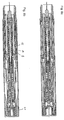
- FIGS 1a, 1b until 9a, b show an injection device of a preferred embodiment.
- the injection device has a housing 1, which consists of a proximal housing part 1a and a distal housing part 1b that is axially fixedly connected to the proximal housing part with a latching connection 1c.
- the latching connection 1c is formed from a window contained in the proximal housing part, into which an elastic tongue formed by the distal housing part 1b is snapped.
- a product container 2 is accommodated in the housing 1, at the distal end of which there is an injection needle 4 for dispensing a liquid product contained in the product container 2.
- the product container 2 has a displaceable piston 3 whose movement relative to the product container 2 and in the direction of the injection needle 4 causes a product to be dispensed, which is why it can also be referred to as a dispensing movement.
- the product container 2 is received in the device in such a way that it can be displaced in the distal direction, so that the injection needle 4 protrudes from the distal end of the injection device. Therefore, one can speak of a piercing movement here.
- the product container 2 is axially fixedly connected to a holder 10 for the product container 2.
- the holder 10 surrounds the product container 2 in the shape of a sleeve, so that it either has a viewing window itself or, as in this example, a transparent material in order to reveal the container 2.
- the product container 2 is at the proximal end with a functional sleeve 11 arranged proximally from it the bracket 10 formed clamp axially firmly connected. At its proximal end, the product container 2 has a radially protruding collar which is gripped by the clamp.
- the functional sleeve 11 also has a radially protruding collar at its distal end, which is likewise encompassed by the clamp.
- product container 10, functional sleeve 11 and holder 10 are axially fixedly connected to one another, so that they can be moved like a single part. This combination is referred to below as the propulsion structure 2, 10, 11.
- the functional sleeve 11 surrounds a piston rod 5, which can act on the piston 3 to dispense product.
- the piston rod 5 has a sleeve-shaped part which surrounds a propulsion spring 6, the propulsion spring 6 being supported distally on the piston rod 5 and proximally on a switching sleeve 8, in particular on a base 8a formed thereon.
- a signaling unit is arranged on the piston rod 5, with which one, preferably at least three or more haptic and / or acoustic signals can be generated for the piercing process and / or the pouring process.
- the signaling unit comprises a latching rod 23 connected to the switching sleeve 8 and an engaging sleeve 22 surrounding the latching rod 23, which is axially fixed to the piston rod 5, in particular is latched.
- the engagement sleeve 22 has an engagement element 26 which engages in a groove 27 formed by the locking rod 23.
- the grid rod 23 At its proximal end, the grid rod 23 has a head 24 which can be moved in the proximal direction in a sliding guide 25 formed by the activation element 13.
- the head is at its distal end in engagement with a base 8a formed by the switching sleeve 8, the engagement preventing the head 24 and thus the locking rod 23 from being movable in the distal direction relative to the switching sleeve 8.
- FIGS. 10 and 11 the signaling unit from the Figures 10 and 11 by another signaling unit according to Figures 12 to 14 and according to yet another signaling unit Figures 15 and 16 be replaced.
- the ones in the Figures 1 to 9 The injection device shown does not have to be changed significantly for this.
- the propulsion spring 6 is pretensioned so that it the needle 4 and in particular the propulsion structure 2, 10, 11 can advance for a piercing movement and move the piston 3 for a dispensing movement.
- the functional sleeve 11 has a locking element 16 on which a radially inwardly directed shoulder is formed, which in the initial state interacts with a radially outwardly projecting shoulder formed on the distal end of the piston rod 5, so that the piston rod 5 moves relative to the functional sleeve 11 is blocked.
- the locking element 16 is held in engagement with the piston rod 5 by a radially inwardly facing surface of the switching sleeve 8.
- the blocking element 16 is preferably connected elastically to the functional sleeve 11 via a spring arm, in particular in one piece.
- the resilient arrangement can be designed in such a way that the locking element 16 tends to move radially outward, this being prevented by the radially inwardly facing surface of the switching sleeve 8.
- the functional sleeve 11 has at least one snap element 15 at its proximal end which, in the initial state, snaps into the switching sleeve 8 to prevent movement of the functional sleeve 11 and thus the propulsion structure 2, 10, 11.
- the pretensioned spring 6 cannot yet relax and the propulsion structure 2, 10, 11 cannot yet move in the distal direction.
- the injection device has an activation element 13 which is arranged axially fixed and rotatable relative to the housing 1.
- the activation element 13 receives a return spring 21 which is supported distally on the proximal end of the switching sleeve 8 and proximally on the activation element 13.
- the restoring spring 21 has the task of applying a force acting in the distal direction to the switching sleeve 8 and an actuating sleeve 9 acting axially on the switching sleeve 8, so that the switching sleeve 8 and the actuating sleeve 9 are pressed in the distal direction.
- the activation element 13 has an activation fuse 14, which is in the Figures 1a, 1b , 2a and 2b
- the switching states of the injection device shown engages behind the snap element 15 in such a way that the snap element 15 is blocked or secured for a movement out of engagement with the switching sleeve 8.
- Accidental triggering of the injection device can thus advantageously be prevented.
- a return spring 7 acting in the longitudinal direction of the device is supported distally on the switching sleeve 8 and proximally on the functional sleeve 11.
- the retraction spring 7 surrounds the switching sleeve 8 and the functional sleeve 11.
- the retraction spring 7 is supported proximally, in particular on a collar 11a formed by the functional sleeve 11, which engages radially outward through an opening formed in the switching sleeve 8 . In certain switching positions, the return spring 7 can therefore bring about a relative movement between the switching sleeve 8 and the functional sleeve 11.
- the return spring 7 is a compression spring which can move the functional sleeve 11 relative to the switching sleeve 8 in the proximal direction.
- the retraction spring 7 is not pretensioned or is preferably pretensioned only with a small pretensioning force.
- the pre-tensioning force of the return spring 7 is less than the pre-tensioning force of the propulsion spring 6.
- the actuating sleeve 9 is arranged so as to be movable relative to the housing 1 distal to the switching sleeve 8.
- the switching sleeve 8 and the actuating sleeve 9 can each act on one another with a compressive force, in particular can be locked to one another and thereby shift. So that the actuating sleeve 9 does not block the view of the product container 2, it also has a window in the area of the window 12.
- the actuating sleeve 9 can be formed from a transparent material.
- the actuating sleeve 9 is advanced by the return spring 21 via the switching sleeve 8 distally over the distal end of the housing 1.
- the distal end of the actuating sleeve 9 is used to be attached to an injection site of a patient.
- the holder 10 has a switching cam 17 which engages in a recess 18 of the actuating sleeve 9, which, as shown in this example, can be a breakthrough.
- the switching cam 17 is resilient to the bracket 10, such. B. via a resilient arm, in particular connected in one piece.
- the switching cam 17 is preferably preloaded in such a way that it tends to engage in the recess 18 or to move radially outward.
- the switching cam 17 protruding radially outward from the holder 10 has a distal inclined surface which can help to push the switching cam 17 out of engagement with the recess 18.
- the switching cam 17 has proximally a transverse, in particular perpendicular to the longitudinal direction of the stop surface, which with the proximal delimitation of the Recess 18 can come into an axial stop through which the switching cam 17 cannot be moved out of the recess 18.
- the actuating sleeve 9 has an axial stop 19 against which the distal end of the holder 10 can strike at the end of a piercing movement.
- a cap 32 is arranged, which protects the interior of the injection device from contamination, in particular keeps the needle 4 sterile.
- the cap 32 is pulled off, so that in particular the needle 4 and the actuating sleeve 9 are exposed, as in FIG Figures 2a and 2b will be shown.
- the one in the Figures 2a and 2b The state of the injection device shown differs from that in the Figures 1a and 1b state shown only in that the cap 32 is removed.
- the force that is exerted on the injection device when the needle cap 32 is withdrawn is passed via the holder 10 to the functional sleeve 11 and there via the snapper 15 to the switching sleeve 8, which is supported on the actuating sleeve 9.
- the actuating sleeve 9 for its part is locked to the housing 1 via a projection 1d formed by the distal housing part 1, so that the removal of the cap 32 from the injection device has no undesirable effect on the mechanics.
- the injection device is shown in an activated state, ie that the injection device can be triggered.
- the injection device is activated or unlocked with a rotary movement of the activation element 13, for. B. by 90 °.
- the snap elements 15 are released for a radially inwardly directed movement in that the activation lock 14 is moved out of engagement with the snap elements 15, in particular is rotated.
- the activation element 13 has an activation cam 13a which is brought into axial alignment with the snap element 15 by the rotary movement of the activation element 13.
- the snap element 15 has proximally and the activation cam 13a arranged proximally thereof has a distal contour which, when the snap element 15 moves into engagement with the activation cam 13, the snap element 15 can deflect radially inward.
- the contours are two inclined planes sliding on each other.
- the user of the device places the distal end of the device on the injection site, which has preferably been disinfected beforehand.
- the actuating sleeve 9 is displaced in the proximal direction relative to the housing 1, preferably until the distal end of the actuating sleeve 9 is approximately flush with the distal end of the distal housing part 1b.
- the switching sleeve 8 is carried along in the proximal direction, the snap elements 15 being pressed out of engagement with the switching sleeve 8, in particular radially inward, by means of the activation cams 13a.
- the elements of the propulsion structure 2, 10, 11 are also carried along in the proximal direction. Since the piston rod 5 is in locking engagement with the functional sleeve 11, the piston rod 5 is also carried along in the proximal direction. Likewise, the signaling unit received in the piston rod 5 is carried along in the proximal direction.
- the head 24 formed proximally on the raster rod 23 can slide along in the guide 25 formed by the activation element 13.
- the force that the user of the device must exert on the housing 1 so that the actuating sleeve 9 is displaced in the proximal direction is essentially determined by the force of the return spring 21, against which the switching sleeve 8 and the actuating sleeve 9 are moved.
- the spring 21 is preferably a compression spring and is formed from a plastic material. Alternatively, of course, springs made of a spring steel material or a other spring material can be used.
- the axial attachment of the activation element 13 to the housing 1 is in the form of an annular snap connection with the housing.
- the release mechanism e.g. the switching sleeve 8 and the actuating sleeve 9 is reset when the injection device is removed from the injection site the return spring 21.
- the propulsion spring 6 can relax partially, as a result of which the propulsion structure 2, 10, 11 is displaced in the distal direction.
- the injection needle 4 protrudes over the distal end of the injection device. Since the functional sleeve 11 is moved relative to the switching sleeve 8 during this piercing movement, the return spring 7 is compressed, i.e. tensioned.
- the spring force of the drive spring 6 is greater than the spring force of the return spring 7 during the entire piercing process, i.e. also at the beginning and at the end of the piercing process. This has the advantage, for example, that the piercing force is reduced, which helps to protect the injection device.
- the locking element 16 engages with a radially outward movement, as indicated by the arrows in FIG Figure 5b is to be shown into the recess 18.
- the locking element 16 has a radially outwardly directed projection.
- the locking element 16 fulfills a double function.
- the locking element 16 engages in the recess 18, the locking element 16 simultaneously disengages from the piston rod 5 with the radially outwardly directed movement, so that the latter is released for a dispensing movement.
- the movement of the propulsion structure 2, 10, 11 in the axial direction, in particular in the proximal direction is blocked.
- the switching cam 17 is pushed out of engagement with the recess 18 by the distal boundary of the recess 18 of the actuating sleeve 9 and displaced in the distal direction so that it engages in the locking window 20, as in FIG Figures 5a and 5b will be shown.
- the locking element 16 latched into the recess 18 is in contact with the proximal delimitation of the recess 18.
- the blocking element 16 and the switching cam 17 are at a defined distance from one another due to their axially fixed arrangement, it is preferred that, when a blocking element 16 is in engagement with the recess, a smaller one between the proximal end of the switching cam and the distal end of the blocking window 20 Distance exists, which in this example is 0.5 to 1 mm. As will be explained below, this distance is used to generate a haptic or acoustic signal which is intended to signal that the product has been completely dispensed.
- the small distance z arises from the difference between the distance between the stop surface of the switching cam 17 pointing in the proximal direction and the stop surface pointing in the proximal direction, and the distance between the proximal boundaries of the recess 18 and the blocking window 20.
- the injection device is shown in a state after a product has been dispensed.
- the outer circumferential surface of the sleeve-shaped part of the piston rod 5 presses the locking element 16 into the recess 18, whereby the blocking element 16 is secured against disengaging from the recess 18 during a product discharge.
- the piston rod 5 can have a recess or its length can be dimensioned such that after the product has been dispensed, the locking element 16 is no longer secured by the outer circumferential surface of the piston rod 5, so that the locking element 16, as in FIG Figure 6b is shown, can disengage from the recess 18.
- the disengagement can be brought about due to an elastically pretensioned arrangement of the locking element 16 or due to the geometry of the locking element 16, which causes the locking element 16 to be pushed out of the recess 18.
- the propulsion spring 6 has relaxed further, while the tension of the tensioned return spring 7 has remained constant.
- the spring force of the drive spring 6 is now less than the spring force of the pretensioned return spring 7.
- the return spring 7 and the drive spring 6 are coupled to one another again.
- This coupling causes, as in the Figures 7a and 7b is shown, the small distance z (see Figures 5b and 6b ) disappears in that the propulsion structure 2, 10, 11, ie in particular the switching cam 17, is suddenly moved with its proximal end onto the distal end of the blocking window 20.
- the switching cam 17 hits, a haptic and / or an acoustic signal is generated.
- the needle 4 is not yet completely withdrawn from the patient.
- the patient or the user of the device can now wait any time until the needle is completely withdrawn from the patient, since he can start the automatic needle retraction of the device by his will.
- FIG Figure 7b A complete movement of the needle into the distal end of the housing 1 is not yet possible, as shown in FIG Figure 7b It can be seen that the switching cam 17 is in engagement with the blocking window 20 and thereby blocks the relaxation of the spring 7. In order to release the withdrawal of the needle 4, the user of the device only needs to remove it from the injection site. As a result, the return spring 21 can move the actuating sleeve 9 in the distal direction via the switching sleeve 8.
- the propulsion structure 2, 10, 11 is fixed relative to the actuating sleeve 9, so that the switching cam 17, driven by its distal design, is pushed radially inward out of the blocking window 20 by the spring 21 in connection with the actuating sleeve 9 by means of the projection 1d.
- the needle 4 is free for retraction.
- the return spring 7 is released for a return movement. Due to the higher spring force of the pre-tensioned return spring 7, the entire propulsion structure 2, 10, 11 is pressed in the proximal direction.
- the spring 6 is tensioned again, the spring force of the retraction spring 7 being greater than the spring force of the propulsion spring 6 during the entire retraction process, ie also until the end of the retraction process.
- the injection device is shown in a final state.
- the injection device has the same dimensions as at the beginning.
- the cap 32 can also be put back on and the injection device disposed of.
- the needle is fully retracted into the distal end of the device.
- the snap element 15 is locked again with the switching sleeve 8 as at the beginning.
- a renewed triggering of the injection device is not possible, since this is a pretensioned propulsion spring 6, as it is, for. Am Figure 1a shown would be necessary.
- the grid rod 23 has a grid 30 which comprises a multiplicity of locking elements 31 which are arranged along the longitudinal direction at intervals that gradually decrease. These distances decrease due to the decreasing spring force.
- the raster rod is axially fixed with its proximal end, in particular with its head, at least in one direction to the switching sleeve 8 (e.g. Figure 1 ) tied together.
- the locking rod 23 is surrounded by a locking sleeve 22 which is connected to the distal end of the propulsion spring 6 and / or to the distal end region of the piston rod 5.
- the engagement sleeve has an engagement element 26 which engages in an annular groove 27.
- the engagement element 26 engages in the groove 27 in the starting position.
- the engagement element disengages from the groove 27 and moves over a first section of the grid rod to the beginning of the plurality of locking elements 31.
- the first section has no further locking element but is essentially cylindrical or tapering so that no signals are emitted during the piercing movement. In principle, embodiments in which this is possible are advantageous.
- the length of the first section is dimensioned such that the engagement element 26 has essentially completely traversed the first section when the puncturing movement has ended.
- the rod 23 and the sleeve 22 are pulled further apart so that the engagement element 26 extends over the second section, that is, the section with the latching element 31 is moved so that the latching elements 31 are each driven over.
- a short click signal is emitted each time the locking elements are driven over.
- the time intervals from one click signal to the next are constant, although the decreasing spring force reduces the speed of the engagement element 26 with increasing travel.
- the distances from one locking element to the next decrease as the spring travel increases. This takes account of the changing speed.
- a further engagement member 26 can be provided, for example.
- no further engagement member 26 is provided, but only a support formed by the sleeve wall, which serves as an abutment.
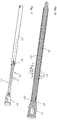
- FIG. 12 to 14 an alternative embodiment of the signaling unit for the injection device from the Figures 1 to 9 shown.
- the grid 30 is arranged in a groove 29, namely on its flank.
- the locking elements 31 protrude in the circumferential direction from the groove flank.
- An axially movable slide 28, which is axially fixedly coupled to the piston rod 5, is arranged in the groove 29.
- the slide 28 is carried along by the piston rod 5, as a result of which the engagement member 26, which is resiliently arranged on the slide 28, passes over the individual latching elements 31 of the grid 30.
- the locking elements 31 are each spaced apart from one another, which take into account the changing force of the propulsion spring for a time-constant output of signals.
- the spacing of the saw teeth is therefore chosen so that the individual clicks take place at regular intervals, although the slide 28 with the piston rod 5 has a lower delivery speed at the end of the delivery than at the beginning.
- Figures 15 and 16 show a further embodiment of the signaling unit in which the grid 30 is formed from recesses, in particular windows, which are also attached to the piston rod 5 at varying distances.
- the engagement member 26 is resiliently arranged on the functional sleeve 11. During the pouring out movement, the piston rod 5 and thus the perforated grid 30 is moved past the engagement member 26, which engages in each perforated grid 31 and thus generates the signal.
- the advantage of this embodiment is that the engagement member 26 can be formed by the locking element 16, so that this embodiment manages with particularly few parts.
Landscapes
- Health & Medical Sciences (AREA)
- Vascular Medicine (AREA)
- Engineering & Computer Science (AREA)
- Anesthesiology (AREA)
- Biomedical Technology (AREA)
- Heart & Thoracic Surgery (AREA)
- Hematology (AREA)
- Life Sciences & Earth Sciences (AREA)
- Animal Behavior & Ethology (AREA)
- General Health & Medical Sciences (AREA)
- Public Health (AREA)
- Veterinary Medicine (AREA)
- Infusion, Injection, And Reservoir Apparatuses (AREA)
Abstract
Description
- Die Erfindung liegt auf dem Gebiet der Injektionsvorrichtungen zum Verabreichen eines flüssigen Produkts, insbesondere Medikaments. Die Erfindung betrifft eine Injektionsvorrichtung und ein Verfahren zum gesteuerten Rückzug einer Nadel aus einer Einstechposition.
- Bei Injektionsvorrichtungen, insbesondere Autoinjektoren ist es bekannt, eine Nadel durch den Mechanismus der Vorrichtung in einen Patienten zu injizieren und anschließend das Produkt durch die Nadel in den Patienten auszuschütten. Nach erfolgter Produktausschüttung wird die Nadel wieder zurück in die Injektionsvorrichtung gezogen.
- Beispielsweise ist aus der
US 6,387,078 B1 eine Injektionsvorrichtung bekannt, bei der eine Nadel mit Hilfe einer Vortriebsfeder zuerst eingestochen und dann mit dieser Vortriebsfeder die Produktausschüttung vorgenommen wird. Beim Vortrieb durch die Vortriebsfeder wird gleichzeitig eine Rückzugsfeder gespannt. Unmittelbar mit Erreichen der Endposition einer Ausschüttbewegung wird die Vortriebsfeder von der Rückzugsfeder entkoppelt, so dass die Rückzugsfeder die Nadel sofort in das Gehäuse zurückzieht. Hierbei kann es vorkommen, dass das Medikament nicht vollständig in das Gewebe des Patienten injiziert wird, so dass ein kleiner Rest verloren geht. Insbesondere bei teueren Medikamenten ist dies ärgerlich. Auch hinsichtlich der tatsächlich verabreichten Dosis kann der verloren gegangene Rest zu Problemen führen. - Aufgabe ist es daher, eine Injektionsvorrichtung und ein Verfahren anzugeben, bei denen der Patient auf einfache Weise bestimmen kann, wann die Nadel eingezogen wird.
- Die Aufgabe wird gelöst durch die Merkmale der unabhängigen Ansprüche 1 und 15. Vorteilhafte Weiterentwicklungen ergeben sich aus den abhängigen Ansprüchen.
- Die Injektionsvorrichtung kann beispielsweise dazu angepasst sein, ein Produkt aus einem Produktbehältnis auszuschütten. Bevorzugt ist die Injektionsvorrichtung ein sog. Autoinjektor, bei dem eine Mechanik vorgesehen ist, die ein selbsttätiges Einstechen der Injektionsnadel und eine anschließende Produktausschüttung ermöglicht. Nach der Produktausschüttung soll die Nadel wieder zurück in die Injektionsvorrichtung gezogen werden.
- Die Injektionsvorrichtung umfasst ein Gehäuse. Das Gehäuse weist ein distales und ein proximales Ende auf. Das distale Ende ist das Ende, an dem die Nadel angeordnet ist. Das proximale Ende ist das dem distalen Ende gegenüberliegende Ende.
- Die Vorrichtung umfasst ferner eine Betätigungshülse, die relativ zu dem Gehäuse bewegbar gelagert ist. Die Betätigungshülse ist mit dem distalen Ende der Injektionsvorrichtung an eine Injektionsstelle des Patienten ansetzbar. Bevorzugt steht die Betätigungshülse über das distale Ende des Gehäuses ein kleines Stück über. Das kleine Stück soll so bemessen sein, dass bei der Bewegung der Betätigungshülse um dieses kleine Stück in proximale Richtung und zurück in die distale Richtung notwendige Schaltvorgänge ausgeführt werden können. Beispielsweise kann dies bei der Bewegung in proximale Richtung die Auslösung einer Einstechbewegung und bei der Bewegung zurück in distale Richtung die Auslösung der Rückzugsbewegung für die Nadel sein. Insbesondere kann ein Elastizitätsmittel, wie z.B. ein Federelement oder eine Feder vorgesehen sein, welches durch die Bewegung der Betätigungshülse in proximale Richtung spannbar ist und/oder mit dem die Betätigungshülse für die Bewegung in distale Richtung antreibbar ist. Das Elastizitätsmittel hat demnach einen rückstellenden Charakter und kann beispielsweise als Rückstellfeder bezeichnet werden. Bevorzugt dient das Elastizitätsmittel dazu, eine zur Auslösung eines Schaltvorgangs nicht ausreichend in die proximale Richtung zurück bewegte Betätigungshülse wieder in die Ausgangsposition zurückzustellen und/oder bei einem Schaltvorgang mitzuwirken, der bei der Bewegung der Betätigungshülse in distale Richtung verursacht wird.
- Vorzugsweise kann die Betätigungshülse aus ihrer distalsten Position soweit in proximale Richtung geschoben werden, dass ihr distales Ende in etwa bündig mit dem distalen Ende des Gehäuses ist, was dem Zustand entspricht bei dem der Verwender die Injektionsvorrichtung an die Injektionsstelle des Patienten angesetzt und aufgedrückt hat.
- Die Vorrichtung umfasst ferner eine Injektionsnadel, welche in einer Einstechposition über das distale Ende der Injektionsvorrichtung hervorsteht. Die Injektionsnadel kann z.B. an einem Produktbehältnis, insbesondere an dessen distalen Ende, angeordnet sein. Zumindest ist die Injektionsnadel fluidisch mit dem inneren des Produktbehältnisses verbunden. Im inneren des Produktbehältnisses befindet sich das zu verabreichende, insbesondere flüssige Produkt. Bei diesem Produkt kann es sich um ein Hormon, wie z.B. ein Wachstumshormon, oder um Insulin zur Diabetesbehandlung oder um ein anderes Medikament handeln. Das Produktbehältnis ist an seinem proximalen Ende mit einem relativ zum Produktbehältnis verschiebbar angeordneten Kolben verschlossen. Bei Bewegung des Kolbens in Richtung distalem Ende des Produktbehältnisses wird das Produkt über die Nadel ausgeschüttet. Bevorzugt ist die Nadel mit dem Produktbehältnis axial fest verbunden.
- Bevorzugt sind die Injektionsnadel und insbesondere auch das Produktbehältnis relativ zum Gehäuse entlang der Längsachse der Injektionsvorrichtung verschiebbar angeordnet. Z.B. kann die Injektionsnadel von einer Ausgangsposition, in der sie sich insbesondere vollständig in dem distalen Ende der Injektionsvorrichtung befindet, d.h., nicht über das distale Ende der Vorrichtung hervorsteht, in die Einstechposition bewegt werden. In der Einstechposition steht die Nadel über das distale Ende der Vorrichtung um solch einen Weg über, der der Tiefe der Injektion der Nadel in das Gewebe des Patienten entspricht. Bevorzugt ist die Injektionsnadel aus der Einstechposition, insbesondere nach einer erfolgten Produktausschüttung, wieder, vorzugsweise vollständig in das distale Ende der Injektionsvorrichtung, d.h., in eine Endposition der Injektionsnadel einziehbar. In der Endposition aber auch in der Ausgangsposition besteht der Vorteil, dass man sich durch die Nadel nicht unbeabsichtigt stechen kann.
- Ferner umfasst die Vorrichtung einen Schaltnocken, der axial fest zu der Injektionsnadel angeordnet ist und in der Einstechposition der Nadel in ein Sperrfenster eingreift. Der Eingriff dient insbesondere dazu, um eine Rückzugsbewegung der Injektionsnadel in das Innere der Injektionsvorrichtung zu verhindern. Dies ist insbesondere gewünscht, wenn eine Produktausschüttung noch nicht vollständig erfolgt ist. Bevorzugt ist der Schaltnocken mittelbar mit der Injektionsnadel verbunden. Z.B. kann der Schaltnocken an einer Halterung für das Produktbehältnis, was bevorzugt ist, oder an dem Produktbehältnis gebildet sein. Insbesondere kann der Schaltnocken an einem Teil der Vortriebsstruktur, die z.B. wenigstens das Produktbehältnis und die Halterung für das Produktbehältnis umfasst, gebildet sein. Bevorzugt ist der Schaltnocken federnd an einem Teil der Vortriebsstruktur gebildet. Beispielsweise ist der Schaltnocken federnd über einen elastischen Arm mit dem Teil der Vortriebsstruktur insbesondere einteilig verbunden. Dies soll jedoch andere federnde Anordnungen nicht ausschließen.
- Das Sperrfenster befindet sich vorzugsweise radial nach außen vom Schaltnocken. Insbesondere kann der Schaltnocken mit einer radial nach außen gerichtete Bewegung in das Sperrfenster eingreifen. Bevorzugt wird das Sperrfenster mit zwei relativ zueinander bewegbaren Teilen distal und proximal begrenzt. Insbesondere begrenzen das Gehäuse oder ein gehäusefestes Element das Sperrfenster distal und die Betätigungshülse das Sperrfenster proximal.
- Weiterhin bevorzugt ist, dass die in Längsrichtung der Injektionsvorrichtung weisende Breite des Sperrfensters veränderbar ist, so dass je nach Breite des Sperrfensters der Schaltnocken in den Eingriff mit dem Sperrfenster bewegbar ist oder aus dem Eingriff mit dem Sperrfenster bewegbar ist. Mit anderen Worten ist die Breite des Sperrfensters dynamisch. Somit kann das Sperrfenster beispielsweise komplett verschwinden, wenn dessen distale und proximale Begrenzungen aneinander stoßen.
- Erfindungsgemäß ist der Schaltnocken mittels der Betätigungshülse aus dem Eingriff mit dem Sperrfenster bewegbar. Hierdurch wird die Injektionsnadel für die Rückzugbewegung aus der Einstechposition in die Endposition freigegeben. Da der Verwender der Vorrichtung über den Anpressdruck der Injektionsvorrichtung an die Injektionsstelle willensabhängig die Position der Betätigungshülse steuern kann, kann er damit den Zeitpunkt, zu dem die Injektionsnadel in das Gehäuse eingezogen wird, selbst bestimmen. Hierzu braucht der Verwender der Vorrichtung lediglich den Anpressdruck der Injektionsvorrichtung auf die Injektionsstelle zu verringern. Insbesondere wird hierdurch die Betätigungshülse in distale Richtung bewegt.
- Besonders bevorzugt wird die Betätigungshülse aus dem Eingriff mit dem Sperrfenster mit der Bewegung der Betätigungshülse in distale Richtung bewegt. Insbesondere wird durch diese Bewegung die in Längsrichtung der Injektionsvorrichtung weisende Breite des Sperrfensters so verringert, insbesondere beseitigt, dass der Schaltnocken aus dem Eingriff mit dem Sperrfenster bewegt wird.
- Der Vorteil der willentlichen Steuerung des Zeitpunkt des Nadelrückzugs besteht darin, dass der Verwender der Vorrichtung selbst bestimmen kann, insbesondere anhand von Erfahrungswerten oder in Abhängigkeit der Viskosität der Flüssigkeit, wie lange die Nadel nach der Produktausschüttung zur vollständigen Produktausschüttung in dem Gewebe verbleiben soll. Ein Faustwert, der jedoch nur beispielhaft genannt wird, ist eine Zeitdauer von 5 Sekunden. Durch diese Wartezeit kann sichergestellt werden, dass sich das flüssige Produkt im Gewebe besser verteilt und das Produkt aufgrund der Trägheit der Produktausschüttung vollständig ausgeschüttet wurde. Dies bietet zum einen wirtschaftlichen Vorteile und zum anderen Vorteile bei der Bestimmung der tatsächlich verabreichten Produktdosis.
- Vorzugsweise sollten, damit der Nadelrückzug erfolgen kann, wenigstens zwei Voraussetzungen erfüllt sein, nämlich dass die Produktausschüttung beendet ist, und die Betätigungshülse in distale Richtung bewegt worden ist.
- Vorzugsweise weist der Schaltnocken eine in proximale Richtung weisende Anschlagfläche auf, die mit der Betätigungshülse so zusammenwirken kann, dass der Schaltnocken von der Betätigungshülse bei einer Bewegung der Betätigungshülse in distale Richtung mitgenommen werden kann, wenn sich der Schaltnocken in dem Sperrfenster befindet. Bevorzugt ist daher auch, dass eine Bewegung des Schaltnockens in proximale Richtung gesperrt ist, wenn die Anschlagfläche des Schaltnockens mit der proximalen Begrenzung des Sperrfensters in einem Anschlag ist. Dies verhindert, dass die Nadel und insbesondere auch die gesamte Vortriebsstruktur in proximale Richtung verschoben wird.
- Insbesondere kann der Schaltnocken in distaler Richtung so geformt sein, dass er von dem Gehäuse oder dem gehäusefesten Element aus dem Eingriff mit dem Sperrfenster bewegbar ist oder/und dass er von der Betätigungshülse aus dem Eingriff mit einer von der Betätigungshülse gebildeten Aussparung bewegbar ist. Beispielsweise kann eine solche Ausformung eine in distale Richtung weisende schräge Fläche sein, die entsprechend dem Prinzip einer schiefen Ebene den Schaltnocken aus dem Sperrfenster bewegt. Bevorzugt ist die Bewegung mit dem der Schaltnocken aus dem Eingriff mit dem Sperrfenster bewegt wird, eine radiale, insbesondere eine radial nach innen gerichtete Bewegung des Schaltnockens.
- Insbesondere in der Ausgangsposition der Vorrichtung kann der Schaltnocken sich in einem Eingriff mit einer von der Betätigungshülse gebildeten Aussparung befinden. Diese Aussparung ist vorzugsweise proximal des Sperrfensters angeordnet. Die Aussparung wird sowohl distal als auch proximal von der Betätigungshülse begrenzt. Die Aussparung kann ein Durchbruch oder eine Tasche sein. Bevorzugt kann der Schaltnocken aus dem Eingriff mit der Aussparung mit einer Bewegung des Schaltnockens in distale Richtung gebracht werden, wie es beispielsweise bei der Bewegung der Nadel aus der Ausgangsposition in die Einstechposition der Fall ist.
- Insbesondere wird bevorzugt, dass sich der Schaltnocken bei einer in das distale Ende der Injektionsvorrichtung zurückgezogenen Position, insbesondere der Ausgangsposition und/oder der Endposition der Injektionsnadel, in einem Eingriff mit der proximal des Sperrfensters gebildeten Aussparung befindet.
- Vorzugsweise weist das Gehäuse oder ein gehäusefestes Element eine radial nach innen weisende Abragung auf, die in einen von der Wandung der Betätigungshülse gebildeten Durchbruch so weit eingreift, dass die radial nach innen weisende Innenfläche der Abragung in etwa bündig mit der radial nach innen weisenden Innenfläche der Betätigungshülse ist. Insbesondere bildet diese Abragung die distale Begrenzung für das Sperrfenster. Aufgrund der Bündigkeit der Innenflächen kann der Sperrnocken problemlos von der Innenfläche der Abragung auf die Innenfläche der Betätigungshülse gleiten, wie das z.B. der Fall ist, wenn die Nadel aus der Einstechposition in die Endposition bewegt wird. Dabei ist das Sperrfenster geschlossen, d. h., dass dessen proximale Begrenzung an die distale Begrenzung anschlägt, so dass die Fensterbreite null ist.
- Besonders bevorzugt ist der Schaltnocken mit einer Rückzugsfeder gekoppelt, mit dem der Schaltnocken und die damit axial fest verbundene Injektionsnadel sowie insbesondere die gesamte Vortriebsstruktur, in proximale Richtung bewegbar sind. Insbesondere ist der Schaltnocken mittelbar mit der Rückzugsfeder gekoppelt, wie z.B. über die Halterung für das Produktbehältnis und eine Funktionshülse, an der sich die Rückzugsfeder, insbesondere mit ihrem proximalen Ende abstützt. Insbesondere können die Halterung und die Funktionshülse axial fest miteinander gekoppelt sein, so dass sie sich wie ein einziges Teil verhalten können.
- Vorzugsweise ist die Rückzugsfeder eine wendelförmige Druckfeder, die mit einer Bewegung der Funktionshülse in distale Richtung vorspannbar und mit einer Bewegung der Funktionshülse in proximale Richtung entspannbar ist. Besonders bevorzugt ist die Rückzugsfeder von einer Vortriebsfeder vorspannbar. Die Vortriebsfeder kann zum Vortrieb der Nadel aus der Ausgangsposition in die Einstechposition und vorzugsweise auch zur Produktausschüttung dienen. In bevorzugten Ausführungsformen ist daher eine einzige Vortriebsfeder ausreichend.
- In bevorzugten Ausführungen kann die Injektionsvorrichtung ein Sperrelement umfassen, welches mit dem Schaltnocken über die Vortriebsstruktur axial fest verbunden ist. Insbesondere ist das Sperrelement über die Funktionshülse und die Halterung für das Produktbehältnis mit dem Schaltnocken verbunden. Hierdurch weisen das Sperrelement und der Schaltnocken zueinander einen fest definierten axialen Abstand auf, der während der gesamten Schaltvorgänge in der Injektionsvorrichtung nicht verändert wird. Das Sperrelement kann in der Einstechposition der Injektionsnadel in einen Eingriff mit der proximal des Sperrfensters von der Betätigungshülse gebildeten Aussparung bewegbar sein. Insbesondere kann das Sperrelement bei Beendigung der Einstechbewegung in den Eingriff mit der Aussparung bewegt werden. Hierdurch wird die Injektionsnadel für einen Rückzug aus der Einstechposition in proximale Richtung blockiert. Insbesondere kann das Sperrelement bei der Bewegung in den Eingriff einen Sperreingriff mit einer auf den Kolben wirkenden Kolbenstange lösen, so dass hierdurch gleichzeitig die Kolbenstange für eine Ausschüttbewegung von der Vortriebsfeder angetrieben wird.
- Des Weiteren kann durch die Bewegung des Sperrelements in den Eingriff mit der Aussparung die Rückzugsfeder von der Vortriebsfeder entkoppelt werden, nachdem die Vortriebsfeder bei der Einstechbewegung die Rückzugsfeder vorgespannt hat.
- Besonders bevorzugt befinden in der Einstechposition der Nadel und insbesondere vor einer vollständig erfolgten Produktausschüttung, d.h., während der Ausschüttbewegung, der Schaltnocken sich in einem Eingriff mit dem Sperrfenster und das Sperrelement sich in einem Eingriff mit der von der Betätigungshülse gebildeten Aussparung. Während diesem Zustand der Injektionsvorrichtung befindet sich zwischen der proximalen Begrenzung des Sperrfensters und der in proximale Richtung weisenden Anschlagfläche des Schaltnockens ein kleiner Abstand, insbesondere von 0,3 bis 3 mm. Das Sperrelement befindet sich hierbei mit seiner in proximale Richtung weisenden Anschlagfläche in Berührung mit der proximalen Begrenzung der Aussparung der Betätigungshülse. Besonders bevorzugt ist der axiale Abstand, der zwischen der in proximalen Richtung weisenden Anschlagfläche des Schaltnockens und der in proximale Richtung weisenden Anschlagfläche des Sperrelements herrscht, größer, insbesondere um den kleinen Abstand größer als der axiale Abstand zwischen der proximalen Begrenzung der Aussparung der Betätigungshülse und der proximalen Begrenzung des Sperrfensters. Durch den genannten kleinen Abstand kann ein haptisches, insbesondere taktiles, oder akustisches Signal erzeugt werden, das die Vollendung der Produktausschüttung anzeigt. Bevorzugt ist, dass die Vortriebsstruktur, und damit das Sperrelement und der Schaltnocken von der Rückzugsfeder um den Betrag des kleinen Abstands in proximale Richtung bewegbar ist. Hierdurch schlägt die in proximale Richtung weisende Anschlagfläche des Schaltnockens schlagartig an die proximale Begrenzung des Sperrfensters an, wodurch das Signal erzeugt wird.
- Bevorzugt kann das Sperrelement nach Beendigung der Produktausschüttung aus dem Eingriff mit der Aussparung ausrasten, wodurch die Rückzugsfeder sich um den kleinen Abstand zur Erzeugung des Signals entspannen kann. Besonders bevorzugt wird, dass ein Ausrasten des Sperrelements aus dem Eingriff mit der Aussparung blockiert ist, insbesondere von der äußeren Umfangsfläche der sich am Sperrelement vorbeibewegenden Kolbenstange.
- Die Erfindung betrifft ferner ein Verfahren zum Einziehen einer aus dem distalen Ende der Injektionsvorrichtung ausgefahrenen Injektionsnadel in das distale Ende, wobei die Betätigungshülse aus dem distalen Ende der Injektionsvorrichtung bewegt und dabei ein in ein Sperrfenster eingreifender Schaltnocken von der Betätigungshülse mitgenommen wird. Bei der Mitnahmebewegung wird der Schaltnocken aus dem Sperrfenster bewegt. Der mit der Injektionsnadel fest verbundene Schaltnocken wird in proximale Richtung bewegt, so dass die ausgefahrene Injektionsnadel in das distale Ende der Injektionsvorrichtung eingezogen wird. Das Verfahren ist vollständig, d. h. mit all seinen Verfahrensschritten, außerhalb des menschlichen oder tierischen Körpers durchführbar.
- Vorteilhafte Verfahrensschritte ergeben sich aus der Arbeitsweise der Vorrichtung.
- Die Erfindung wird nun anhand von Figuren beschrieben. Die in den Figuren offenbarten Merkmale bilden die Erfindung je einzeln und in Kombination mit den oben beschriebenen Merkmalen die Erfindung vorteilhaft weiter.
- Es zeigen:
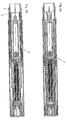
- Figuren 1a und 1b
- Schnittdarstellung einer erfindungsgemäßen Injektionsvorrichtung mit einer aufgesetzten Kappe, wobei
Figur 1b eine gegenüberFigur 1a um 90° um die Längsachse gedrehte Ansicht ist, - Figuren 2a und 2b
- Schnittdarstellungen der Injektionsvorrichtung mit einer abgenommenen Kappe, wobei
Figur 2b eine gegenüberFigur 2a um 90° um die Längsachse gedrehte Ansicht ist, - Figuren 3a und 3b
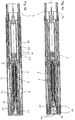
- Schnittdarstellungen der erfindungsgemäßen Injektionsvorrichtung in einem aktivierten Zustand, wobei
Figur 3b eine gegenüberFigur 3a um 90° um die Längsachse gedrehte Ansicht ist, - Figuren 4a und 4b
- Schnittdarstellungen der in erfindungsgemäßen Injektionsvorrichtung in einem ausgelösten Zustand, wobei
Figur 4b eine gegenüberFigur 4a um 90° um die Längsachse gedrehte Ansicht ist, - Figuren 5a und 5b
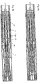
- Schnittdarstellungen der erfindungsgemäßen Injektionsvorrichtung in einem eingestochenen Zustand, wobei
Figur 5b eine gegenüberFigur 5a um 90° um die Längsachse gedrehte Ansicht ist, - Figuren 6a und 6b
- Schnittdarstellungen der erfindungsgemäßen Injektionsvorrichtung in einem ausgeschütteten Zustand, wobei
Figur 6b eine gegenüberFigur 6a um 90° um die Längsachse gedrehte Ansicht ist, - Figuren 7a und 7b
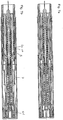
- Schnittdarstellungen der erfindungsgemäßen Injektionsvorrichtung in einem Zustand, in dem die Injektionsvorrichtung ein das Ende der Ausschüttung signalisierendes Klickgeräusch abgegeben hat, wobei
Figur 7b eine gegenüberFigur 7a um 90° um die Längsachse gedrehte Ansicht ist, - Figuren 8a und 8b
- Schnittdarstellungen der erfindungsgemäßen Injektionsvorrichtung bei der ein Rückzug der Injektionsnadel aktiviert ist, wobei
Figur 8b eine gegenüberFigur 8a um 90° um die Längsachse gedrehte Ansicht ist, - Figuren 9a und 9b
- Schnittdarstellungen der erfindungsgemäßen Injektionsvorrichtung in einem Endzustand, wobei
Figur 9b eine gegenüberFigur 9a um 90° um die Längsachse gedrehte Ansicht ist, - Figur 10
- eine Schnittdarstellung der Signalisierungseinheit aus den
Figuren 1 bis 9 , - Figur 11
- eine perspektivische Ansicht der Signalisierungseinheit aus
Figur 10 , - Figur 12
- eine erfindungsgemäße Injektionsvorrichtung mit einer anderen Ausführungsform einer Signalisierungseinheit,
- Figur 13
- eine Schnittdarstellung der Signalisierungseinheit aus
Figur 12 , - Figur 14
- eine weitere Schnittdarstellung der Signalisierungseinheit aus
Figur 12 , und - Figur 15 und 16
- eine weitere Ausführungsform einer erfindungsgemäßen Signalisierungseinheit.
- Sofern nichts anderes angegeben wird, bezeichnen gleiche Bezugszeichen die gleichen Teile.
-
Figuren 1a, 1b bis9a, b zeigen eine Injektionsvorrichtung einer bevorzugten Ausführungsform. Insbesondere bezugnehmend auf dieFiguren 1a und 1b weist die Injektionsvorrichtung ein Gehäuse 1 auf, das aus einem proximalen Gehäuseteil 1a und einem mit dem proximalen Gehäuseteil mit einer Rastverbindung 1c axial fest verbundenes, distales Gehäuseteil 1b. Die Rastverbindung 1c wird gebildet aus einem im proximalen Gehäuseteil enthaltenen Fenster, in welches eine vom distalen Gehäuseteil 1b gebildete elastische Zunge eingeschnappt ist. - Im Gehäuse 1 ist ein Produktbehältnis 2 aufgenommen, an dessen distalem Ende sich eine Injektionsnadel 4 zur Ausschüttung eines in dem Produktbehältnis 2 enthaltenen flüssigen Produkts befindet. Am proximalen Ende weist das Produktbehältnis 2 einen verschiebbaren Kolben 3 auf, dessen Bewegung relativ zum Produktbehältnis 2 und in Richtung Injektionsnadel 4 eine Produktausschüttung bewirkt, weshalb auch von einer Ausschüttbewegung gesprochen werden kann. Das Produktbehältnis 2 ist so in der Vorrichtung aufgenommen, dass es in distale Richtung verschiebbar ist, so dass die Injektionsnadel 4 aus dem distalen Ende der Injektionsvorrichtung hervortritt. Deshalb kann hier von einer Einstechbewegung die Rede sein. Das Produktbehältnis 2 ist axial fest mit einer Halterung 10 für das Produktbehältnis 2 verbunden. Das Gehäuse 1, insbesondere dessen distale und proximale Gehäuseteile 1a, 1b weisen ein Sichtfenster 12 auf, durch das der Verwender der Injektionsvorrichtung einen Blick auf das Produktbehältnis 2 werfen kann. Die Halterung 10 umgibt das Produktbehältnis 2 hülsenförmig, so dass es, um den Blick auf das Behältnis 2 freizugeben, entweder selbst ein Sichtfenster oder wie in diesem Beispiel ein transparentes Material aufweist. Das Produktbehältnis 2 ist mit einer proximal von ihr angeordneten Funktionshülse 11 am proximalen Ende der Halterung 10 gebildeten Klammer axial fest verbunden. Das Produktbehältnis 2 weist an seinem proximalen Ende einen radial abstehenden Kragen auf, der von der Klammer gefasst wird. Die Funktionshülse 11 weist an ihrem distalen Ende auch einen radial abstehenden Kragen auf, der ebenfalls von der Klammer umgriffen wird. Somit sind Produktbehältnis 10, Funktionshülse 11 und Halterung 10 axial fest miteinander verbunden, so dass sie sich wie ein einziges Teil bewegen lassen. Im Folgenden wird diese Kombination als Vortriebsstruktur 2, 10, 11 bezeichnet.
- Die Funktionshülse 11 umgibt eine Kolbenstange 5, die für eine Produktausschüttung auf den Kolben 3 wirken kann. Die Kolbenstange 5 weist einen hülsenförmigen Teil auf, der eine Vortriebsfeder 6 umgibt, wobei sich die Vortriebsfeder 6 distal an der Kolbenstange 5 und proximal an einer Schalthülse 8, insbesondere an einem daran gebildeten Sockel 8a abstützt.
- An der Kolbenstange 5 ist eine Signalisierungseinheit angeordnet, mit der für den Einstechvorgang und/oder den Ausschüttvorgang ein, vorzugsweise mindestens drei oder mehrere haptische und/oder akustische Signale erzeugbar sind. Die Signalisierungseinheit umfasst eine mit der Schalthülse 8 verbundene Rasterstange 23 und eine die Rasterstange 23 umgebende Eingriffshülse 22, welche mit der Kolbenstange 5 axial fest verbunden, insbesondere verrastet ist. Die Eingriffshülse 22 weist ein Eingriffselement 26 auf, das in eine von der Rasterstange 23 gebildete Nut 27 eingreift. Die Rasterstange 23 weist an ihrem proximalen Ende einen Kopf 24 auf, der in einer von dem Aktivierungselement 13 gebildeten Gleitführung 25 in proximale Richtung bewegbar ist. Der Kopf ist mit seinem distalen Ende in einem Eingriff mit einem von der Schalthülse 8 gebildeten Sockel 8a, wobei der Eingriff verhindert, dass der Kopf 24 und damit die Rasterstange 23 in distale Richtung relativ zur Schalthülse 8 bewegbar ist. Die genaue Funktionsweise dieser Anordnung wird später unter Bezugnahme auf die Figuren 10 und 11 erklärt, in denen die in den
Figuren 1 bis 9 gezeigte Signalisierungseinheit im Detail dargestellt ist. Alternativ kann die Signalisierungseinheit aus denFiguren 10 und 11 durch eine andere Signalisierungseinheit gemäßFiguren 12 bis 14 und noch einer anderen Signalisierungseinheit gemäßFiguren 15 und 16 ersetzt werden. Die in denFiguren 1 bis 9 gezeigt Injektionsvorrichtung muss hierzu nicht wesentlich geändert werden. - In dem in den
Figuren 1a und 1b gezeigten Ausgangszustand der Injektionsvorrichtung ist die Vortriebsfeder 6 vorgespannt, so dass sie die Nadel 4 und insbesondere die Vortriebsstruktur 2, 10, 11 für eine Einstechbewegung vorantreiben und den Kolben 3 für eine Ausschüttbewegung verschieben kann. Die Funktionshülse 11 weist ein Sperrelement 16 auf, an dem eine radial nach innen gerichtete Schulter ausgebildet ist, die im Ausgangszustand mit einer am distalen Ende der Kolbenstange 5 gebildeten radial nach außen stehenden Schulter zusammenwirkt, so dass die Kolbenstange 5 für eine Bewegung relativ zur Funktionshülse 11 gesperrt ist. Das Sperrelement 16 wird von einer radial nach innen weisenden Fläche der Schalthülse 8 in dem Eingriff mit der Kolbenstange 5 gehalten. Bevorzugt ist das Sperrelement 16 über einen Federarm elastisch mit der Funktionshülse 11 verbunden, insbesondere einteilig. Die federnde Anordnung kann so gestaltet sein, dass das Sperrelement 16 dazu tendiert, sich radial nach außen zu bewegen, wobei dies durch die radial nach innen weisende Fläche der Schalthülse 8 verhindert wird. - Die Funktionshülse 11 weist an ihrem proximalen Ende mindestens ein Schnappelement 15 auf, welches im Ausgangszustand zur Verhinderung einer Bewegung der Funktionshülse 11 und damit der Vortriebsstruktur 2, 10, 11 in die Schalthülse 8 einschnappt. Hierdurch kann die vorgespannte Feder 6 sich noch nicht entspannen und die Vortriebsstruktur 2, 10, 11 noch nicht in distale Richtung bewegen.
- Die Injektionsvorrichtung weist am proximalen Ende ihres Gehäuses 1 ein Aktivierungselement 13 auf, welches zum Gehäuse 1 axial fest und drehbar angeordnet ist. Das Aktivierungselement 13 nimmt eine Rückstellfeder 21 auf, die sich distal am proximalen Ende der Schalthülse 8 und proximal an dem Aktivierungselement 13 abstützt. Die Rückstellfeder 21 hat die Aufgabe, die Schalthülse 8 und eine axial auf die Schalthülse 8 wirkende Betätigungshülse 9 mit einer in distale Richtung wirkenden Kraft zu beaufschlagen, so dass Schalthülse 8 und Betätigungshülse 9 in distale Richtung gedrückt werden. Das Aktivierungselement 13 weist eine Aktivierungssicherung 14 auf, die in den in den
Figuren 1a, 1b ,2a und 2b gezeigten Schaltzuständen der Injektionsvorrichtung das Schnappelement 15 so hintergreift, dass das Schnappelement 15 für eine Bewegung aus dem Eingriff mit der Schalthülse 8 blockiert bzw. gesichert ist. Somit kann vorteilhaft ein versehentliches Auslösen der Injektionsvorrichtung verhindert werden. Durch Drehung des Aktivierungselements 13 z. B. um 90° relativ zum Gehäuse 1 kann die Aktivierungssicherung aus dem Eingriff mit dem Schnappelement 15 bewegt werden. - Eine in Längsrichtung der Vorrichtung wirkende Rückzugsfeder 7 stützt sich distal an der Schalthülse 8 und proximal an der Funktionshülse 11 ab. Wie in diesem Beispiel gezeigt wird, umgibt die Rückzugsfeder 7 die Schalthülse 8 und die Funktionshülse 11. Die Rückzugsfeder 7 stützt sich proximal insbesondere an einem von der Funktionshülse 11 gebildeten Bund 11a ab, der radial nach außen durch einen in der Schalthülse 8 gebildeten Durchbruch greift. In bestimmten Schaltpositionen kann daher die Rückzugsfeder 7 eine Relativbewegung zwischen der Schalthülse 8 und der Funktionshülse 11 bewirken. Die Rückzugsfeder 7 ist eine Druckfeder, welche die Funktionshülse 11 relativ zur Schalthülse 8 in proximale Richtung bewegen kann. Die Rückzugsfeder 7 ist nicht oder bevorzugt nur mit einer geringen Vorspannkraft vorgespannt. Beispielsweise in dem in den
Figuren 1a und 1b gezeigten Zustand der Injektionsvorrichtung ist die Vorspannkraft der Rückzugsfeder 7 geringer als die Vorspannkraft der Vortriebsfeder 6. - Distal der Schalthülse 8 ist die Betätigungshülse 9 relativ zum Gehäuse 1 bewegbar angeordnet. Die Schalthülse 8 und die Betätigungshülse 9 können sich jeweils gegenseitig mit einer Druckkraft beaufschlagen, insbesondere miteinander verrastet sein und sich dadurch verschieben. Damit die Betätigungshülse 9 die Sicht auf das Produktbehältnis 2 nicht blockiert, weist sie im Bereich des Fensters 12 ebenfalls ein Fenster auf. Alternativ kann die Betätigungshülse 9 aus einem transparenten Material gebildet sein. Die Betätigungshülse 9 wird im Ausgangszustand von der Rückstellfeder 21 über die Schalthülse 8 distal über das distale Ende des Gehäuses 1 vorgeschoben. Das distale Ende der Betätigungshülse 9 dient dazu, an eine Injektionsstelle eines Patienten angesetzt zu werden.
- Die Halterung 10 weist einen Schaltnocken 17 auf, der in eine Aussparung 18 der Betätigungshülse 9 eingreift, die, wie in diesem Beispiel gezeigt wird, ein Durchbruch sein kann. Der Schaltnocken 17 ist elastisch mit der Halterung 10, wie z. B. über einen federnden Arm, insbesondere einteilig verbunden. Der Schaltnocken 17 ist vorzugsweise so vorgespannt, dass er dazu neigt, in die Aussparung 18 einzugreifen bzw. sich radial nach außen zu bewegen. Der radial von der Halterung 10 nach außen abragende Schaltnocken 17 weist distal eine schräge Fläche auf, die dabei mitwirken kann, den Schaltnocken 17 aus dem Eingriff mit der Aussparung 18 zu drücken. Ferner weist der Schaltnocken 17 proximal eine quer, insbesondere senkrecht zur Längsrichtung stehende Anschlagfläche auf, die mit der proximalen Begrenzung der Aussparung 18 in einen Axialanschlag geraten kann, durch den der Schaltnocken 17 nicht aus der Aussparung 18 bewegt werden kann.
- Die Betätigungshülse 9 weist einen Axialanschlag 19 auf, an dem das distale Ende der Halterung 10 am Ende einer Einstechbewegung anschlagen kann.
- Am distalen Ende der Injektionsvorrichtung ist, wie in den
Figuren 1a und 1b gezeigt wird, eine Kappe 32 angeordnet, welche das innere der Injektionsvorrichtung vor Verschmutzung schützt, insbesondere die Nadel 4 steril hält. Vor Verwendung der Injektionsvorrichtung wird die Kappe 32 abgezogen, so dass insbesondere die Nadel 4 und die Betätigungshülse 9 freiliegen, wie in denFiguren 2a und 2b gezeigt wird. Der in denFiguren 2a und 2b gezeigte Zustand der Injektionsvorrichtung unterscheidet sich von dem in denFiguren 1a und 1b gezeigten Zustand lediglich dadurch, dass die Kappe 32 abgenommen ist. - Die Kraft, die bei beim Abzug der Nadelkappe 32 auf die Injektionsvorrichtung ausgeübt wird, wird über die Halterung 10 auf die Funktionshülse 11 geleitet und dort über die Schnapper 15 auf die Schalthülse 8 übergeben, welche sich an der Betätigungshülse 9 abstützt. Die Betätigungshülse 9 ist ihrerseits mit dem Gehäuse 1 über eine vom distalen Gehäuseteil 1 gebildete Abragung 1d verrastet, so dass das Abziehen der Kappe 32 von der Injektionsvorrichtung keine unerwünschte Auswirkung auf die Mechanik ausübt.
- In dem in den
Figuren 2a und 2b gezeigten Schaltzustand kann die Betätigungshülse 9 nicht oder nur sehr geringfügig in das distale Ende der Injektionsvorrichtung hineingeschoben werden, da diese Verschiebebewegung über die Schalthülse 8 an den Schnapper 15 weitergeleitet wird, wobei der Schnapper 15 an einer Bewegung in proximale Richtung durch das Aktivierungselement 13 gehindert wird. - In den
Figuren 3a und 3b wird die Injektionsvorrichtung in einem aktivierten Zustand gezeigt, d.h., dass die Injektionsvorrichtung auslösbar ist. Aktiviert bzw. entriegelt wird die Injektionsvorrichtung mit einer Drehbewegung des Aktivierungselements 13 z. B. um 90°. Hierbei werden die Schnappelemente 15 für eine radial nach innen gerichtete Bewegung dadurch freigegeben, dass die Aktivierungssicherung 14 aus dem Eingriff mit den Schnappelementen 15 bewegt, insbesondere gedreht wird. Somit besteht Raum für die Schnappelemente 15 nach innen hin ausgelenkt zu werden. Ferner weist das Aktivierungselement 13 wie das Schnappelement 15 einen Aktivierungsnocken 13a auf, der durch die Drehbewegung des Aktivierungselements 13 in eine axiale Flucht mit dem Schnappelement 15 gebracht wird. Das Schnappelement 15 weist proximal und der proximal davon angeordnete Aktivierungsnocken 13a weist distal eine Kontur auf, welche bei der Bewegung des Schnappelements 15 in einem Eingriff mit dem Aktivierungsnocken 13 das Schnappelement 15 radial nach innen auslenken kann. In diesem Beispiel sind die Konturen zwei aufeinander abgleitende schiefe Ebenen. - Zur Auslösung der Injektionsvorrichtung setzt der Verwender der Vorrichtung diese mit dem distalen Ende auf die vorzugsweise vorher desinfizierte Injektionsstelle. Hierdurch wird die Betätigungshülse 9 relativ zum Gehäuse 1 in proximale Richtung verschoben, vorzugsweise soweit, bis das distale Ende der Betätigungshülse 9 in etwa bündig mit dem distalen Ende des distalen Gehäuseteils 1b ist. Durch die Bewegung der Betätigungshülse 9 wird die Schalthülse 8 in proximale Richtung mitgenommen, wobei die Schnappelemente 15 mittels der Aktivierungsnocken 13a aus dem Eingriff mit der Schalthülse 8 insbesondere radial nach innen gedrückt werden. Mit der Bewegung der Betätigungshülse 9 in distale Richtung werden, solange die Schnappelemente 15 in die Schalthülse 8 eingeschnappt sind, auch die Elemente der Vortriebsstruktur 2, 10, 11 in proximale Richtung mitgenommen. Da die Kolbenstange 5 mit der Funktionshülse 11 sich in einem Sperreingriff befindet, wird auch die Kolbenstange 5 in proximale Richtung mitgenommen. Ebenso wird die in der Kolbenstange 5 aufgenommene Signalisierungseinheit in proximale Richtung mitgenommen. Der proximal an der Rasterstange 23 gebildete Kopf 24 kann in der vom Aktivierungselement 13 gebildeten Führung 25 entlanggleiten.
- Da bei dieser Bewegung noch keine Relativbewegung zwischen der Aktivierungshülse 11 und der Schalthülse 8 stattfinden kann, werden weder die Rückzugsfeder 7 noch die Vortriebsfeder 6 ge- oder entspannt.
- Die Kraft, die der Verwender der Vorrichtung auf das Gehäuse 1 ausüben muss, damit die Betätigungshülse 9 in proximale Richtung verschoben wird, bestimmt sich im Wesentlichen über die Kraft der Rückstellfeder 21, gegen die die Schalthülse 8 und die Betätigungshülse 9 bewegt werden. Die Feder 21 ist vorzugsweise eine Druckfeder und aus einem Kunststoffmaterial gebildet. Alternativ sind natürlich auch Federn aus einem Federstahlwerkstoff oder einem anderen Federwerkstoff verwendbar. Die axiale Befestigung des Aktivierungselements 13 an dem Gehäuse 1 besteht in der Gestalt einer Ringschnappverbindung mit dem Gehäuse. Wird die Betätigungshülse 9 nicht ausreichend weit auf die Injektionsstelle gedrückt, so dass die Schnappelemente 15 nicht aus dem Eingriff mit der Schalthülse 8 gelöst sind, erfolgt beim Abnehmen der Injektionsvorrichtung von der Injektionsstelle eine Rückstellung der Auslösemechanik, z.B. der Schalthülse 8 und der Betätigungshülse 9 durch die Rückstellfeder 21.
- Wie aus
Figur 4b erkennbar ist, wird durch die Bewegung der Betätigungshülse 9 in proximale Richtung ein Sperrfenster 20 gebildet, welches distal von dem Gehäuse 1, insbesondere der Abragung 1d und proximal von der Betätigungshülse 9 begrenzt ist. Da bei der Bewegung der Betätigungshülse 9 in proximale Richtung noch keine Relativbewegung zwischen der Vortriebsstruktur 2, 10, 11 und der Betätigungshülse 9 stattfindet, verbleibt der Schaltnocken 17 in der Aussparung 18. - Nachdem die Schnapper 15 aus dem Eingriff mit der Schalthülse 8 ausgerastet sind, kann sich die Vortriebsfeder 6 teilweise entspannen, wodurch die Vortriebsstruktur 2, 10, 11 in distale Richtung verschoben wird. Dabei tritt die Injektionsnadel 4 über das distale Ende der Injektionsvorrichtung hervor. Da bei dieser Einstechbewegung die Funktionshülse 11 relativ zur Schalthülse 8 bewegt wird, wird die Rückzugsfeder 7 komprimiert, d.h. gespannt. Die Federkraft der Vortriebsfeder 6 ist während des gesamten Einstechvorgangs, d.h. auch am Anfang und am Ende des Einstechvorgangs größer als die Federkraft der Rückzugsfeder 7. Dies hat z.B. den Vorteil, dass die Einstechkraft reduziert wird, was zur Schonung der Injektionsvorrichtung beiträgt.
- Wie aus den
Figuren 5a und 5b , in denen die Situation am Ende der Einstechvorrichtung gezeigt ist, ersichtlich ist, greift das Sperrelement 16 mit einer radial nach außen gerichteten Bewegung, wie mit den Pfeilen inFigur 5b gezeigt werden soll, in die Aussparung 18 ein. Um diesen Eingriff zu verbessern weist das Sperrelement 16 eine radial nach außen gerichtete Abragung auf. Das Sperrelement 16 erfüllt eine Doppelfunktion. Beim Einrasten des Sperrelements 16 in die Aussparung 18 rastet gleichzeitig das Sperrelement 16 mit der nach radial außen gerichteten Bewegung aus der Kolbenstange 5 aus, so dass diese für eine Ausschüttbewegung freigegeben ist. Im Gegenzug wird die Bewegung der Vortriebsstruktur 2, 10, 11 in axiale Richtung, insbesondere in proximale Richtung gesperrt. Durch diesen Vorgang wird die Vorschubfeder 6 von der Rückzugsfeder 7 entkoppelt, d.h., dass die Vorschubfeder 6 in diesem Zustand keinen Einfluss auf die Vorspannung der Rückzugsfeder 7 hat. Es folgt eine Ausschüttbewegung, bei der durch die Signalisierungseinheit ein zeitkonstantes Klickgeräusch abgegeben wird, das vom Verwender der Vorrichtung auch fühlbar ist. - Für den Verwender der Vorrichtung wird durch den Einstechvorgang keine zusätzliche Kraft spürbar. Diese wird durch die Verschnappung zwischen der Betätigungshülse 9 und der Schalthülse 8 gefangen und stützt sich nicht am Gehäuse ab. Die Kraft für den Einstechvorgang wird über die Funktionshülse 11 an den Kragen des Produktbehältnisses 2 geleitet. Somit ist der Einstechvorgang zwangsgesteuert, da die Funktionshülse 11 bis zum Ende der Ausschüttung das Produktbehältnis 2 vorantreibt und die Kolbenstange 5 erst nach dem Eingriff der Sperrelemente 16 in die Aussparungen 18 ausschütten kann. Die Einstechbewegung wird durch den Anschlag 19 an der Betätigungshülse 9 gestoppt.
- Bei der Einstechbewegung wird der Schaltnocken 17 aufgrund seiner distalen Gestaltung von der distalen Begrenzung der Aussparung 18 der Betätigungshülse 9 aus dem Eingriff mit der Aussparung 18 gedrückt und in distale Richtung verschoben, so dass er in das Sperrfenster 20 einrastet, wie in den
Figuren 5a und 5b gezeigt wird. Das in die Aussparung 18 eingerastete Sperrelement 16 steht mit der proximalen Begrenzung der Aussparung 18 in Kontakt. Da das Sperrelement 16 und der Schaltnocken 17 aufgrund ihrer axial festen Anordnung zueinander in einem definierten Abstand stehen, ist es bevorzugt, dass bei einem im Eingriff mit der Aussparung stehenden Sperrelement 16 zwischen dem proximalen Ende des Schaltnockens und dem distalen Ende des Sperrfensters 20 ein kleiner Abstand besteht, der in diesem Beispiel 0,5 bis 1 mm beträgt. Dieser Abstand wird, wie weiter unten erklärt wird, zur Erzeugung eines haptischen oder akustischen Signals verwendet, welches die vollständige Produktausschüttung signalisieren soll. Der kleine Abstand z entsteht aus der Differenz aus dem Abstand, der zwischen der in proximale Richtung weisenden Anschlagfläche des Schaltnockens 17 und der in proximale Richtung weisenden Anschlagfläche herrscht, und dem Abstand der proximalen Begrenzungen der Aussparung 18 und des Sperrfensters 20. - In den
Figuren 6a und 6b wird die Injektionsvorrichtung in einem Zustand nach einer erfolgten Produktausschüttung gezeigt. Während der Produktausschüttung drückt die äußere Umfangsfläche des hülsenförmigen Teils der Kolbenstange 5 das Sperrelement 16 in die Aussparung 18, wodurch das Sperrelement 16 während einer Produktausschüttung gegen ein Ausrasten aus der Aussparung 18 gesichert ist. Die Kolbenstange 5 kann eine Aussparung aufweisen oder von der Länge her so bemessen sein, dass nach erfolgter Produktausschüttung die Sicherung des Sperrelements 16 durch die äußere Umfangsfläche der Kolbenstange 5 wegfällt, so dass das Sperrelement 16, wie inFigur 6b gezeigt wird, aus der Aussparung 18 ausrasten kann. Das Ausrasten kann aufgrund einer elastisch vorgespannten Anordnung des Sperrelements 16 oder aufgrund der Geometrie des Sperrelements 16, die ein Herausdrücken des Sperrelements 16 aus der Aussparung 18 verursacht, bewirkt werden. - Am Ende der Produktausschüttung hat sich die Vortriebsfeder 6 weiter entspannt, während die Spannung der gespannten Rückzugsfeder 7 konstant geblieben ist. Die Federkraft der Vortriebsfeder 6 ist nun geringer, als die Federkraft der vorgespannten Rückzugsfeder 7. Durch das Lösen des Eingriffs des Sperrelements 16 mit der Aussparung 18 werden die Rückzugsfeder 7 und die Vortriebsfeder 6 wieder miteinander gekoppelt. Diese Kopplung bewirkt, dass wie in den
Figuren 7a und 7b dargestellt ist, der kleine Abstand z (sieheFiguren 5b und6b ) verschwindet, indem die Vortriebsstruktur 2, 10, 11, d. h. insbesondere der Schaltnocken 17 mit seinem proximalen Ende schlagartig auf das distale Ende des Sperrfensters 20 bewegt wird. Beim Aufschlagen des Schaltnockens 17 wird ein haptisches und/oder ein akustisches Signal erzeugt. Durch diese Bewegung um den kleinen Weg z wird die Nadel 4 jedoch noch nicht vollständig aus dem Patienten herausgezogen. Der Patient bzw. der Verwender der Vorrichtung kann nun eine beliebige Zeit warten, bis die Nadel vollständig aus dem Patienten herausgezogen wird, da er den automatischen Nadelrückzug der Vorrichtung durch seinen Willen starten kann. - Eine vollständige Bewegung der Nadel in das distale Ende des Gehäuses 1 ist noch nicht möglich, da, wie aus
Figur 7b ersichtlich ist, der Schaltnocken 17 in dem Eingriff mit dem Sperrfenster 20 ist und dadurch die Entspannung der Feder 7 blockiert. Um den Rückzug der Nadel 4 freizugeben, braucht der Verwender der Vorrichtung diese nur von der Injektionsstelle nehmen. Dadurch kann die Rückstellfeder 21 über die Schalthülse 8 die Betätigungshülse 9 in distale Richtung bewegen. Dabei steht die Vortriebsstruktur 2, 10, 11 relativ zur Betätigungshülse 9 fest, so dass der Schaltnocken 17 augrund seiner distalen Gestaltung angetrieben durch die Feder 21 in Verbindung mit der Betätigungshülse 9 mittels der Abragung 1d aus dem Sperrfenster 20 radial nach innen gedrückt wird. Sobald der Schaltnocken 17 nach innen gedrückt wurde, ist die Nadel 4 für den Rückzug frei. Außerdem wird durch das Lösen des Eingriffs die Rückzugsfeder 7 für eine Rückzugsbewegung freigegeben. Aufgrund der höheren Federkraft der vorgespannten Rückzugsfeder 7 wird die gesamte Vortriebsstruktur 2, 10, 11 in proximale Richtung gedrückt. Hierbei wird die Feder 6 wieder gespannt, wobei die Federkraft der Rückzugsfeder 7 während des gesamten Rückzugsvorgangs, d.h. auch bis zum Ende des Rückzugsvorgangs, größer ist als die Federkraft der Vortriebsfeder 6. - In den
Figuren 9a und 9b wird die Injektionsvorrichtung in einem Endzustand gezeigt. In diesem Zustand hat die Injektionsvorrichtung wieder die gleichen Dimensionen wie am Anfang. Somit kann auch die Kappe 32 wieder aufgesetzt und die Injektionsvorrichtung entsorgt werden. In der Endposition ist die Nadel vollständig in das distale Ende der Vorrichtung eingezogen. Das Schnappelement 15 ist wieder mit der Schalthülse 8 wie am Anfang verrastet. Eine erneute Auslösung der Injektionsvorrichtung ist jedoch nicht möglich, da hierfür eine vorgespannte Vortriebsfeder 6, wie sie z. B. inFigur 1a gezeigt wird, notwendig wäre. - In den
Figuren 10 und 11 wird die Signalisierungseinheit derFiguren 1 bis 9 im Detail gezeigt. Die Rasterstange 23 weist ein Raster 30 auf, welches eine Vielzahl von Rastelementen 31 umfasst, die entlang der Längsrichtung mit sich schrittweise verringernden Abständen angeordnet sind. Diese Abstände verringern sich anhand der nachlassenden Federkraft. Die Rasterstange ist mit seinem proximalen Ende, insbesondere mit seinem Kopf zumindest in eine Richtung axial fest mit der Schalthülse 8 (z. B.Figur 1 ) verbunden. Die Rasterstange 23 ist von einer Rasterhülse 22 umgeben, die mit dem distalen Ende der Vortriebsfeder 6 oder/und mit dem distalen Endbereich der Kolbenstange 5 verbunden ist. Die Eingriffshülse weist ein Eingriffselement 26 auf, das in eine ringförmige Nut 27 eingreift. Insbesondere greift das Eingriffselement 26 in der Ausgangsposition in die Nut 27 ein. Bei der Vorschubbewegung zum Einstechen, d.h. bei der Einstechbewegung rastet das Eingriffselement aus der Nut 27 aus und bewegt sich über einen ersten Abschnitt der Rasterstange bis zum Anfang der Vielzahl der Rastelemente 31. Der erste Abschnitt weist kein weiteres Rastelement auf sondern ist im Wesentlichen zylinderförmig oder sich verjüngend, so dass bei der Einstechbewegung keine Signale abgegeben werden. Grundsätzlich sind Ausführungsformen, bei denen dies möglich ist vorteilhaft. Die Länge des ersten Abschnitts ist so bemessen, dass das Eingriffselement 26 im Wesentlichen den ersten Abschnitt vollständig durchfahren hat bei Beendigung der Einstichbewegung. Beim Start der Ausschüttbewegung werden Stange 23 und Hülse 22 noch weiter auseinander gezogen, so dass das Eingriffselement 26 sich über den zweiten Abschnitt, d.h. den Abschnitt mit dem Rastelement 31, bewegt, so dass die Rastelemente 31 jeweils überfahren werden. Bei jedem Überfahren der Rastelemente wird ein kurzes Klick-Signal abgegeben. Die Zeitintervalle von einem Klick-Signal bis zum nächsten sind konstant, obwohl die nachlassende Federkraft die Geschwindigkeit des Eingriffselements 26 mit zunehmendem Weg verringert. Erfindungsgemäß verringern sich die Abstände von einem Rastelement zum nächsten mit zunehmendem Federweg. Dadurch wird der sich verändernden Geschwindigkeit Rechnung getragen. - Auf der radial gegenüberliegenden Seite, an der das Eingriffsglied 26 angeordnet ist, kann beispielsweise ein weiteres Eingriffsglied 26 vorgesehen sein. Bevorzugt ist, wie hier dargestellt wird, kein weiteres Eingriffsglied 26 vorgesehen, sondern lediglich eine von der Hülsenwandung gebildete Stütze, die als Widerlager dient.
- In den
Figuren 12 bis 14 wird eine alternative Ausführungsform der Signalisierungseinheit für die Injektionsvorrichtung aus denFiguren 1 bis 9 gezeigt. Das Raster 30 ist in einer Nut 29, nämlich an dessen Flanke angeordnet. Die Rastelemente 31 stehen in Umfangsrichtung von der Nutflanke ab. In der Nut 29 ist ein axial bewegbarer Schlitten 28 angeordnet, der axial fest mit der Kolbenstange 5 gekoppelt ist. Bei der Ausschüttbewegung wird der Schlitten 28 durch die Kolbenstange 5 mitgenommen, wodurch das am Schlitten 28 federnd angeordnete Eingriffsglied 26 die einzelnen Rastelemente 31 des Rasters 30 überfährt. Auch hier haben die Rastelemente 31 jeweils Abstände voneinander, die der sich verändernden Kraft der Vortriebsfeder für eine zeitkonstante Abgabe von Signalen Rechnung tragen. Der Abstand der Sägezähne ist also gewählt, dass die einzelnen Klicks in gleichmäßigen Zeitabständen erfolgen, obwohl der Schlitten 28 mit der Kolbenstange 5 am Ende der Ausschüttung eine geringere Ausschüttgeschwindigkeit ausweist als am Anfang. -
Figuren 15 und 16 zeigen eine weitere Ausführungsform der Signalisierungseinheit, bei der das Raster 30 aus Ausnehmungen, insbesondere Fenstern gebildet ist, die ebenfalls mit sich verändernden Abständen auf der Kolbenstange 5 angebracht sind. Das Eingriffsglied 26 ist an der Funktionshülse 11 federnd angeordnet. Bei der Ausschüttbewegung wird die Kolbenstange 5 und somit das Lochraster 30 an dem Eingriffsglied 26 vorbeibewegt, das jeweils in jedes Lochraster 31 einrastet und somit das Signal erzeugt. Der Vorteil an dieser Ausführungsform ist, dass das Eingriffsglied 26 von dem Sperrelement 16 gebildet werden kann, so dass diese Ausführungsform mit besonders wenigen Teilen auskommt. -
- 1
- Gehäuse
- 1a
- proximales Gehäuseteil
- 1b
- distales Gehäuseteil
- 1c
- Rastverbindung
- 1d
- Abragung
- 2
- Produktbehältnis
- 3
- Kolben
- 4
- Injektionsnadel
- 5
- Kolbenstange
- 6
- Vortriebsfeder
- 7
- Rückzugsfeder
- 8
- Schalthülse
- 8a
- Sockel
- 9
- Betätigungshülse
- 10
- Produktbehältnishalterung
- 11
- Funktionshülse
- 11a
- Bund
- 12
- Sichtfenster
- 13
- Aktivierungselement
- 13a
- Aktivierungsnocken
- 14
- Aktivierungssicherung
- 15
- Schnappelement
- 16
- Sperrelement
- 17
- Schaltnocken
- 18
- Aussparung
- 19
- Axialanschlag
- 20
- Sperrfenster
- 21
- Rückstellfeder
- 22
- Eingriffshülse
- 23
- Rasterstange
- 24
- Kopf
- 25
- Gleitführung
- 26
- Eingriffsglied
- 27
- Nut
- 28
- Schlitten
- 29
- Nut
- 30
- Raster
- 31
- Rastelement
- 32
- Kappe
- z
- Abstand
- x0
- Abstand
- x0-Δx
- veränderter Abstand
- L
- Längsachse
Claims (4)
- Autoinjektor zur Verabreichung eines flüssigen Produkts, umfassend:a) ein Gehäuse (1) mit Längsrichtung,b) ein im Gehäuse aufgenommenes Produktbehältnis (2) an dessen distalem Ende sich eine Injektionsnadel (4) zur Ausschüttung eines in dem Produktbehältnis enthaltenen flüssigen Produkts befindet, wobei in einer Einstechposition die Injektionsnadel (4) über ein distales Ende der Injektionsvorrichtung hervorsteht,c) eine Kolbenstange (5), welche für eine Produktausschüttung auf einen im Produktbehältnis (2) verschiebbaren Kolben wirken kann,d) eine Signalisierungseinheit mit einem Raster (30) umfassend eine Vielzahl von Rastelementen (31), die entlang der Längsrichtung angeordnet sind, und mit einem federnden Eingriffselement (26), welches sich bei einer Ausschüttbewegung über die Rastelemente bewegt so dass bei Überfahren der Rastelemente ein Klick-Signal abgegeben wird,
dadurch gekennzeichnet, dasse) der Raster (30) aus auf der Kolbenstange (5) angebrachten Ausnehmungen gebildet ist und das Eingriffselement (26) von einem Sperrelement (16) gebildet ist [Seite 20, Zeile 27ff; 3. Ausführungsform der Signalisierungseinheit], wobei das Sperrelement (16) im Ausgangszustand von einer radial nach innen weisenden Fläche einer Schalthülse (8) in einem Eingriff mit der Kolbenstange (5) gehalten ist [Seite 12, Zeile 6; Duale Funktion des Sperrelements als Klickelement]. - Autoinjektor nach Anspruch 1, dadurch gekennzeichnet, dass die Rastelemente (31) mit einem sich schrittweise verringernden Abstand angeordnet sind.
- Autoinjektor nach Anspruch 2, dadurch gekennzeichnet, dass die Rastelemente (31) mit dem sich schrittweise verringernden Abstand so angeordnet sind, dass ein Zeitintervall von einem Klick-Signal zum nächsten konstant bleibt.
- Autoinjektor nach Anspruch 3, umfassend eine Vortriebsfeder (6) zur Ausschüttung des flüssigen Produkts, dadurch gekennzeichnet, dass der sich verringernde Abstand zwischen den Rastelementen (31) einer durch nachlassende Federkraft der Vortriebsfeder verringerten Geschwindigkeit des Eingriffsglieds Rechnung trägt.
Applications Claiming Priority (4)
| Application Number | Priority Date | Filing Date | Title |
|---|---|---|---|
| DE102007013836A DE102007013836A1 (de) | 2007-03-22 | 2007-03-22 | Injektionsvorrichtung mit gesteuertem Nadelrückzug |
| PCT/CH2008/000118 WO2008113198A1 (de) | 2007-03-22 | 2008-03-19 | Injektionsvorrichtung mit gesteuertem nadelrückzug |
| EP08714768.2A EP2129415B1 (de) | 2007-03-22 | 2008-03-19 | Injektionsvorrichtung mit gesteuertem nadelrückzug |
| EP18196181.4A EP3461517A1 (de) | 2007-03-22 | 2008-03-19 | Injektionsvorrichtung mit signalisierungseinheit |
Related Parent Applications (3)
| Application Number | Title | Priority Date | Filing Date |
|---|---|---|---|
| EP18196181.4A Division EP3461517A1 (de) | 2007-03-22 | 2008-03-19 | Injektionsvorrichtung mit signalisierungseinheit |
| EP18196181.4A Previously-Filed-Application EP3461517A1 (de) | 2007-03-22 | 2008-03-19 | Injektionsvorrichtung mit signalisierungseinheit |
| EP08714768.2A Division EP2129415B1 (de) | 2007-03-22 | 2008-03-19 | Injektionsvorrichtung mit gesteuertem nadelrückzug |
Publications (1)
| Publication Number | Publication Date |
|---|---|
| EP3865161A1 true EP3865161A1 (de) | 2021-08-18 |
Family
ID=41265585
Family Applications (3)
| Application Number | Title | Priority Date | Filing Date |
|---|---|---|---|
| EP21162068.7A Ceased EP3865161A1 (de) | 2007-03-22 | 2008-03-19 | Injektionsvorrichtung mit gesteuertem nadelrückzug |
| EP08714768.2A Active EP2129415B1 (de) | 2007-03-22 | 2008-03-19 | Injektionsvorrichtung mit gesteuertem nadelrückzug |
| EP18196181.4A Withdrawn EP3461517A1 (de) | 2007-03-22 | 2008-03-19 | Injektionsvorrichtung mit signalisierungseinheit |
Family Applications After (2)
| Application Number | Title | Priority Date | Filing Date |
|---|---|---|---|
| EP08714768.2A Active EP2129415B1 (de) | 2007-03-22 | 2008-03-19 | Injektionsvorrichtung mit gesteuertem nadelrückzug |
| EP18196181.4A Withdrawn EP3461517A1 (de) | 2007-03-22 | 2008-03-19 | Injektionsvorrichtung mit signalisierungseinheit |
Country Status (3)
| Country | Link |
|---|---|
| US (1) | US8043262B2 (de) |
| EP (3) | EP3865161A1 (de) |
| CN (1) | CN101678168B (de) |
Families Citing this family (50)
| Publication number | Priority date | Publication date | Assignee | Title |
|---|---|---|---|---|
| CN104324438B (zh) | 2008-01-11 | 2017-06-16 | Ucb医药有限公司 | 用于类风湿性关节炎患者的给药系统 |
| MX384690B (es) | 2008-05-20 | 2025-03-14 | Avant Medical Corp | Sistema auto-inyector. |
| US8052645B2 (en) | 2008-07-23 | 2011-11-08 | Avant Medical Corp. | System and method for an injection using a syringe needle |
| US8177749B2 (en) | 2008-05-20 | 2012-05-15 | Avant Medical Corp. | Cassette for a hidden injection needle |
| US12097357B2 (en) | 2008-09-15 | 2024-09-24 | West Pharma. Services IL, Ltd. | Stabilized pen injector |
| EP2401009B1 (de) | 2009-02-26 | 2012-11-28 | Tecpharma Licensing AG | Produktbehältnishalter für eine injektionsvorrichtung und zur aufnahme eines produktbehältnisses |
| WO2011040861A1 (en) * | 2009-09-30 | 2011-04-07 | Shl Group Ab | Medicament delivery device |
| EP2399635A1 (de) | 2010-06-28 | 2011-12-28 | Sanofi-Aventis Deutschland GmbH | Automatischer Injektor |
| EP2468337A1 (de) * | 2010-12-21 | 2012-06-27 | Sanofi-Aventis Deutschland GmbH | Back-End-Vorrichtung für einen automatischen Injektor und automatischer Injektor |
| EP2489385A1 (de) | 2011-02-18 | 2012-08-22 | Sanofi-Aventis Deutschland GmbH | Automatischer Injektor |
| EP2489390A1 (de) | 2011-02-18 | 2012-08-22 | Sanofi-Aventis Deutschland GmbH | Arretierungsmechanismus |
| EP2489387A1 (de) | 2011-02-18 | 2012-08-22 | Sanofi-Aventis Deutschland GmbH | Automatischer Injektor |
| EP2489380A1 (de) | 2011-02-18 | 2012-08-22 | Sanofi-Aventis Deutschland GmbH | Injektionsvorrichtung |
| EP2489389A1 (de) * | 2011-02-18 | 2012-08-22 | Sanofi-Aventis Deutschland GmbH | Arretierungsmechanismus |
| EP2489386A1 (de) * | 2011-02-18 | 2012-08-22 | Sanofi-Aventis Deutschland GmbH | Automatischer Injektor |
| EP2489384A1 (de) | 2011-02-18 | 2012-08-22 | Sanofi-Aventis Deutschland GmbH | Automatischer Injektor |
| EP2489381A1 (de) | 2011-02-18 | 2012-08-22 | Sanofi-Aventis Deutschland GmbH | Automatischer Injektor |
| EP2489388A1 (de) | 2011-02-18 | 2012-08-22 | Sanofi-Aventis Deutschland GmbH | Automatischer Injektor |
| EP2489382A1 (de) | 2011-02-18 | 2012-08-22 | Sanofi-Aventis Deutschland GmbH | Automatischer Injektor |
| WO2012122643A1 (en) * | 2011-03-11 | 2012-09-20 | University Of Saskatchewan | Injection assist device and method |
| CA3021845C (en) | 2011-04-20 | 2022-03-29 | Amgen Inc. | Autoinjector apparatus |
| ES2542250T3 (es) | 2011-06-02 | 2015-08-03 | Ucb Biopharma Sprl | Autoinyector |
| MX348444B (es) * | 2011-08-31 | 2017-06-12 | Shl Group Ab | Dispositivo de inyección. |
| EP2572741A1 (de) | 2011-09-23 | 2013-03-27 | Sanofi-Aventis Deutschland GmbH | Medikamentenabgabevorrichtung und Auslösemechanismus für eine Medikamentenabgabevorrichtung |
| EP2583704A1 (de) * | 2011-10-21 | 2013-04-24 | Sanofi-Aventis Deutschland GmbH | Autoinjektor |
| EP2606925A1 (de) * | 2011-12-21 | 2013-06-26 | Sanofi-Aventis Deutschland GmbH | Autoinjektor |
| PL2836259T3 (pl) * | 2012-04-11 | 2016-11-30 | Uchwyt wkładu i iniektor typu pen | |
| USD898908S1 (en) | 2012-04-20 | 2020-10-13 | Amgen Inc. | Pharmaceutical product cassette for an injection device |
| USD808010S1 (en) | 2012-04-20 | 2018-01-16 | Amgen Inc. | Injection device |
| EP2879738B1 (de) | 2012-07-30 | 2019-09-11 | UCB Biopharma SPRL | Automatischer injektor |
| EP2879737B1 (de) | 2012-07-30 | 2018-09-12 | UCB Biopharma SPRL | Automatischer injektor |
| US9764101B2 (en) | 2012-07-30 | 2017-09-19 | Ucb Biopharma Sprl | Auto-injector |
| CH705155A2 (de) * | 2012-10-08 | 2012-11-30 | Tecpharma Licensing Ag | Injektionsvorrichtung zur Aufdosierung und zur Ausschüttung einer festgelegten Dosis eines fluiden Produkts. |
| TWI580451B (zh) | 2013-03-15 | 2017-05-01 | 安美基公司 | 用於注射器之匣盒及使用具有自動注射器及匣盒之自動注射器設備之方法 |
| EP2968775B1 (de) | 2013-03-15 | 2019-12-18 | Amgen Inc. | Medikamentenkassette, autoinjektor und autoinjektorsystem |
| EP2823841A1 (de) | 2013-07-09 | 2015-01-14 | Sanofi-Aventis Deutschland GmbH | Autoinjektor |
| US10342925B2 (en) | 2014-01-27 | 2019-07-09 | Ucb Biopharma Sprl | Auto-injector |
| US9821123B2 (en) | 2014-01-27 | 2017-11-21 | Ucb Biopharma Sprl | Auto-injector |
| EP2923714A1 (de) | 2014-03-28 | 2015-09-30 | Sanofi-Aventis Deutschland GmbH | Durch hautkontakt ausgelöste Autoinjektor |
| CN112237662B (zh) | 2014-06-03 | 2022-10-21 | 安姆根有限公司 | 药物递送系统和使用方法 |
| GB2530714A (en) * | 2014-08-20 | 2016-04-06 | Owen Mumford Ltd | Injection devices |
| EP3848072A1 (de) | 2014-12-19 | 2021-07-14 | Amgen Inc. | Medikamentenabgabevorrichtung mit näherungssensor |
| US11357916B2 (en) | 2014-12-19 | 2022-06-14 | Amgen Inc. | Drug delivery device with live button or user interface field |
| US9415176B1 (en) | 2015-01-22 | 2016-08-16 | West Pharmaceutical Services, Inc. | Autoinjector having an end-of-dose visual indicator |
| GB2545266B (en) * | 2015-12-11 | 2018-08-08 | Oval Medical Tech Limited | Autoinjector with retracting needle |
| KR102257732B1 (ko) * | 2016-05-06 | 2021-05-31 | 에스에이치엘 메디컬 아게 | 약물 전달 장치용 구동 조립체 |
| CN107468289A (zh) * | 2017-08-03 | 2017-12-15 | 宋瑞昕 | 埋线器 |
| CH712459A2 (de) * | 2017-08-31 | 2017-11-15 | Tecpharma Licensing Ag | Antriebsvorrichtung für Injektionsgeräte. |
| CA3208266C (en) | 2019-02-22 | 2024-04-16 | Deka Products Limited Partnership | Infusion set and inserter assembly systems and methods |
| US12539361B2 (en) | 2019-02-22 | 2026-02-03 | Deka Products Limited Partnership | Infusion set and inserter assembly apparatuses, systems, and methods |
Citations (6)
| Publication number | Priority date | Publication date | Assignee | Title |
|---|---|---|---|---|
| WO1999003529A2 (en) * | 1997-07-16 | 1999-01-28 | Owen Mumford Limited | Improvements relating to injection devices |
| DE10015616A1 (de) * | 2000-03-29 | 2001-10-04 | Peter Mueller | Injektionsspritze für die Zahnheilkunde |
| US6387078B1 (en) | 2000-12-21 | 2002-05-14 | Gillespie, Iii Richard D. | Automatic mixing and injecting apparatus |
| WO2004035117A1 (de) * | 2002-10-15 | 2004-04-29 | Tecpharma Licensing Ag | Injektionsvorrichtung mit leerhub |
| WO2006052737A1 (en) * | 2004-11-04 | 2006-05-18 | Sid Technologies, Llc | Automatic injector |
| DE202007000578U1 (de) * | 2007-01-15 | 2007-03-08 | Cilag Gmbh International | Injektionsvorrichtung |
Family Cites Families (8)
| Publication number | Priority date | Publication date | Assignee | Title |
|---|---|---|---|---|
| US4194505A (en) * | 1978-09-15 | 1980-03-25 | Vac-O-Cast, Inc. | Containerized hypodermic module |
| GB9111600D0 (en) | 1991-05-30 | 1991-07-24 | Owen Mumford Ltd | Improvements relating to injection devices |
| FR2736553B1 (fr) * | 1995-07-12 | 1998-01-09 | Soc Et Et D Applic Tech Sedat | Seringue d'injection, notamment de produits medicaux liquides, a protecteur d'aiguille mobile |
| FR2774294B1 (fr) | 1998-02-04 | 2000-04-14 | Marc Brunel | Dispositif d'injection automatique d'une dose de produit medicamenteux |
| AU2003278798A1 (en) | 2002-09-12 | 2004-04-30 | Children's Hospital Medical Center | Method and device for painless injection of medication |
| GB2396816A (en) | 2002-12-17 | 2004-07-07 | Pa Consulting Services | Injection device |
| DK1743666T3 (da) | 2005-07-15 | 2009-08-24 | Shl Group Ab | Injektor med automatisk indföring af nål, injektion og udtrækning af nål |
| US9320459B2 (en) * | 2006-05-08 | 2016-04-26 | Becton, Dickinson And Company | Gravity-drop safety holder |
-
2008
- 2008-03-19 CN CN2008800094232A patent/CN101678168B/zh active Active
- 2008-03-19 EP EP21162068.7A patent/EP3865161A1/de not_active Ceased
- 2008-03-19 EP EP08714768.2A patent/EP2129415B1/de active Active
- 2008-03-19 EP EP18196181.4A patent/EP3461517A1/de not_active Withdrawn
-
2009
- 2009-09-21 US US12/563,789 patent/US8043262B2/en active Active
Patent Citations (6)
| Publication number | Priority date | Publication date | Assignee | Title |
|---|---|---|---|---|
| WO1999003529A2 (en) * | 1997-07-16 | 1999-01-28 | Owen Mumford Limited | Improvements relating to injection devices |
| DE10015616A1 (de) * | 2000-03-29 | 2001-10-04 | Peter Mueller | Injektionsspritze für die Zahnheilkunde |
| US6387078B1 (en) | 2000-12-21 | 2002-05-14 | Gillespie, Iii Richard D. | Automatic mixing and injecting apparatus |
| WO2004035117A1 (de) * | 2002-10-15 | 2004-04-29 | Tecpharma Licensing Ag | Injektionsvorrichtung mit leerhub |
| WO2006052737A1 (en) * | 2004-11-04 | 2006-05-18 | Sid Technologies, Llc | Automatic injector |
| DE202007000578U1 (de) * | 2007-01-15 | 2007-03-08 | Cilag Gmbh International | Injektionsvorrichtung |
Also Published As
| Publication number | Publication date |
|---|---|
| EP3461517A1 (de) | 2019-04-03 |
| CN101678168B (zh) | 2013-03-06 |
| EP2129415A1 (de) | 2009-12-09 |
| US8043262B2 (en) | 2011-10-25 |
| US20100137801A1 (en) | 2010-06-03 |
| CN101678168A (zh) | 2010-03-24 |
| EP2129415B1 (de) | 2018-10-24 |
Similar Documents
| Publication | Publication Date | Title |
|---|---|---|
| EP2129415B1 (de) | Injektionsvorrichtung mit gesteuertem nadelrückzug | |
| WO2008113198A1 (de) | Injektionsvorrichtung mit gesteuertem nadelrückzug | |
| EP4103251B1 (de) | Autoinjektor mit einer nadelschutzhülse | |
| EP2170434B1 (de) | Injektionsvorrichtung mit einer feder für eine nadelschutzhülse | |
| EP2129416A1 (de) | Federanordnung in einer injektionsvorrichtung | |
| EP3421067B1 (de) | Injektionsvorrichtung, insbesondere autoinjektor mit stechschutz oder/und überlastsicherung für ein produktbehältnis | |
| EP3280472B1 (de) | Injektionsvorrichtung mit gewinde mit einer variablen steigung | |
| DE102007013838A1 (de) | Injektionsvorrichtung mit zeitkonstantem Ausschüttsignal | |
| EP1703929B1 (de) | Auslösbares injektionsgerät | |
| EP2742962B1 (de) | Autoinjektor mit einer Signalisierungseinrichtung am Ende der Produktausschüttung | |
| EP3610908B1 (de) | Autoinjektor mit bewegbarem nadelschutz | |
| EP3744370B1 (de) | Sicherheitseinrichtung für injektionsvorrichtungen | |
| EP2745866B1 (de) | Auslösesicherung für einen autoinjektor | |
| DE102004064159B4 (de) | Autoinjektor mit Arretierung des Wirkstoffbehälters | |
| EP0956875B1 (de) | Vorrichtung zur dosierten Verabreichung eines injizierbaren Produkts | |
| DE60120224T2 (de) | Autoinjektor | |
| WO2008113864A1 (de) | Injektionsvorrichtung mit auslösesicherungen | |
| EP1233801B1 (de) | Injektionsvorrichtung | |
| WO2022184388A1 (de) | Autoinjektor mit einer nadelschutzhülse | |
| DE10351594A1 (de) | Vorrichtung für die Verabreichung eines injizierbaren Produkts | |
| WO2007051330A1 (de) | Autoinjektor-aktivierung auslöseelement | |
| WO2010136076A1 (de) | Injektionsvorrichtung mit einer einrichtung zum trennen einer nadelschutzkappe von einem produktbehältnis | |
| EP2335771A1 (de) | Vorrichtung zur Injektion eines Feststoffes | |
| CH695926A5 (de) | Vorrichtung zum automatischen Injizieren eines Wirkstoffes. | |
| CH696423A5 (de) | Autoinjektor. |
Legal Events
| Date | Code | Title | Description |
|---|---|---|---|
| PUAI | Public reference made under article 153(3) epc to a published international application that has entered the european phase |
Free format text: ORIGINAL CODE: 0009012 |
|
| STAA | Information on the status of an ep patent application or granted ep patent |
Free format text: STATUS: THE APPLICATION HAS BEEN PUBLISHED |
|
| AC | Divisional application: reference to earlier application |
Ref document number: 3461517 Country of ref document: EP Kind code of ref document: P Ref document number: 2129415 Country of ref document: EP Kind code of ref document: P |
|
| AK | Designated contracting states |
Kind code of ref document: A1 Designated state(s): AT BE BG CH CY CZ DE DK EE ES FI FR GB GR HR HU IE IS IT LI LT LU LV MC MT NL NO PL PT RO SE SI SK TR |
|
| STAA | Information on the status of an ep patent application or granted ep patent |
Free format text: STATUS: REQUEST FOR EXAMINATION WAS MADE |
|
| 17P | Request for examination filed |
Effective date: 20220218 |
|
| RBV | Designated contracting states (corrected) |
Designated state(s): AT BE BG CH CY CZ DE DK EE ES FI FR GB GR HR HU IE IS IT LI LT LU LV MC MT NL NO PL PT RO SE SI SK TR |
|
| STAA | Information on the status of an ep patent application or granted ep patent |
Free format text: STATUS: EXAMINATION IS IN PROGRESS |
|
| 17Q | First examination report despatched |
Effective date: 20220913 |
|
| STAA | Information on the status of an ep patent application or granted ep patent |
Free format text: STATUS: THE APPLICATION HAS BEEN REFUSED |
|
| 18R | Application refused |
Effective date: 20240204 |