EP3865042B1 - Heat recovery oven with dishwasher - Google Patents
Heat recovery oven with dishwasher Download PDFInfo
- Publication number
- EP3865042B1 EP3865042B1 EP21157704.4A EP21157704A EP3865042B1 EP 3865042 B1 EP3865042 B1 EP 3865042B1 EP 21157704 A EP21157704 A EP 21157704A EP 3865042 B1 EP3865042 B1 EP 3865042B1
- Authority
- EP
- European Patent Office
- Prior art keywords
- water
- oven
- dishwasher
- firebox
- water tank
- Prior art date
- Legal status (The legal status is an assumption and is not a legal conclusion. Google has not performed a legal analysis and makes no representation as to the accuracy of the status listed.)
- Active
Links
Images

Classifications
-
- A—HUMAN NECESSITIES
- A47—FURNITURE; DOMESTIC ARTICLES OR APPLIANCES; COFFEE MILLS; SPICE MILLS; SUCTION CLEANERS IN GENERAL
- A47L—DOMESTIC WASHING OR CLEANING; SUCTION CLEANERS IN GENERAL
- A47L15/00—Washing or rinsing machines for crockery or tableware
- A47L15/0097—Combination of dishwashers with other household appliances
-
- F—MECHANICAL ENGINEERING; LIGHTING; HEATING; WEAPONS; BLASTING
- F24—HEATING; RANGES; VENTILATING
- F24C—DOMESTIC STOVES OR RANGES ; DETAILS OF DOMESTIC STOVES OR RANGES, OF GENERAL APPLICATION
- F24C13/00—Stoves or ranges with additional provisions for heating water
-
- F—MECHANICAL ENGINEERING; LIGHTING; HEATING; WEAPONS; BLASTING
- F24—HEATING; RANGES; VENTILATING
- F24C—DOMESTIC STOVES OR RANGES ; DETAILS OF DOMESTIC STOVES OR RANGES, OF GENERAL APPLICATION
- F24C15/00—Details
- F24C15/32—Arrangements of ducts for hot gases, e.g. in or around baking ovens
- F24C15/322—Arrangements of ducts for hot gases, e.g. in or around baking ovens with forced circulation
-
- A—HUMAN NECESSITIES
- A47—FURNITURE; DOMESTIC ARTICLES OR APPLIANCES; COFFEE MILLS; SPICE MILLS; SUCTION CLEANERS IN GENERAL
- A47L—DOMESTIC WASHING OR CLEANING; SUCTION CLEANERS IN GENERAL
- A47L15/00—Washing or rinsing machines for crockery or tableware
- A47L15/42—Details
- A47L15/4285—Water-heater arrangements
-
- A—HUMAN NECESSITIES
- A47—FURNITURE; DOMESTIC ARTICLES OR APPLIANCES; COFFEE MILLS; SPICE MILLS; SUCTION CLEANERS IN GENERAL
- A47L—DOMESTIC WASHING OR CLEANING; SUCTION CLEANERS IN GENERAL
- A47L15/00—Washing or rinsing machines for crockery or tableware
- A47L15/42—Details
- A47L15/4291—Recovery arrangements, e.g. for the recovery of energy or water
-
- A—HUMAN NECESSITIES
- A47—FURNITURE; DOMESTIC ARTICLES OR APPLIANCES; COFFEE MILLS; SPICE MILLS; SUCTION CLEANERS IN GENERAL
- A47L—DOMESTIC WASHING OR CLEANING; SUCTION CLEANERS IN GENERAL
- A47L2401/00—Automatic detection in controlling methods of washing or rinsing machines for crockery or tableware, e.g. information provided by sensors entered into controlling devices
- A47L2401/09—Water level
-
- A—HUMAN NECESSITIES
- A47—FURNITURE; DOMESTIC ARTICLES OR APPLIANCES; COFFEE MILLS; SPICE MILLS; SUCTION CLEANERS IN GENERAL
- A47L—DOMESTIC WASHING OR CLEANING; SUCTION CLEANERS IN GENERAL
- A47L2401/00—Automatic detection in controlling methods of washing or rinsing machines for crockery or tableware, e.g. information provided by sensors entered into controlling devices
- A47L2401/12—Water temperature
-
- A—HUMAN NECESSITIES
- A47—FURNITURE; DOMESTIC ARTICLES OR APPLIANCES; COFFEE MILLS; SPICE MILLS; SUCTION CLEANERS IN GENERAL
- A47L—DOMESTIC WASHING OR CLEANING; SUCTION CLEANERS IN GENERAL
- A47L2501/00—Output in controlling method of washing or rinsing machines for crockery or tableware, i.e. quantities or components controlled, or actions performed by the controlling device executing the controlling method
- A47L2501/01—Water supply, e.g. opening or closure of the water inlet valve
-
- F—MECHANICAL ENGINEERING; LIGHTING; HEATING; WEAPONS; BLASTING
- F24—HEATING; RANGES; VENTILATING
- F24C—DOMESTIC STOVES OR RANGES ; DETAILS OF DOMESTIC STOVES OR RANGES, OF GENERAL APPLICATION
- F24C15/00—Details
- F24C15/18—Arrangement of compartments additional to cooking compartments, e.g. for warming or for storing utensils or fuel containers; Arrangement of additional heating or cooking apparatus, e.g. grills
Definitions
- the present invention relates to a heat recovery oven with dishwasher that combines both dishwashing and cooking functions in a single structure.
- the present invention allows for taking advantage of these two functions at the same time or at different times.
- the present invention particularly relates to a household appliance that not only occupies less space as it is capable of performing both washing and cooking functions simultaneously but also saves energy by using the heat generated in the oven section during cooking for heating the water to be used in the dishwasher.
- Heating devices used for cooking, drying, melting, or exposing a substance to a heat process within an enclosed area and for controlling the temperature for various aims are called ovens.
- ovens are used in many different fields. For instance, ovens are used for preparing and cooking food in household kitchens, in medium-sized industrial enterprises such as restaurants, diners, cafes, hotel kitchens, in the food industry, for producing porcelain or glass in the cement industry, iron and steel industry, and aluminum industry.
- the heat energy in the ovens can be generated by using fuels such as coal, fuel oil, or natural gas in solid, liquid, or gas form, or by using electricity or solar heat.
- Ovens may vary as gas ovens, electric turbo ovens, multifunctional and static ovens, or based on their purpose of use, they may be classified as household type ovens and industrial type ovens. There are household-type ovens that are used for cooking food at appropriate temperatures and under suitable conditions, contain one or more properties as thermostatic, static, turbo, etc., and provide heat with the help of conventional electric or natural gas.
- EP2196126A1 describes a system with a heat exchanger that is used for transferring heat between the kitchen appliances (such as oven and dishwasher, etc.).
- the invention disclosed in said application comprises at least two different household appliances, utilizes a heat exchanger for exchanging air to water, and water is heated with hot air.
- the utility model application numbered CN2772495Y discloses a system in which the oven firebox is cooled with water.
- the aim is to prevent the liquid and solid food spilled from the cooked foods to the base of the oven firebox from burning in extreme heat and emitting odor and smoke. Therefore, it is aimed to eliminate the burning smell in cooked food.
- the present invention eliminating the disadvantages in the state of the art, relates to a heat recovery household appliance that consists of two parts and that offers the functions of both a dishwasher and an oven.
- the present invention relates to an energy-saving multifunctional household appliance that comprises two separate sections in which the functions of an oven and a dishwasher are provided in a single construct.
- the present invention transfers the waste heat between different functions of a single household appliance.
- an object of the present invention is to develop a household appliance that comprises both oven and dishwasher within a single body.
- dishes may be washed in the dishwasher while food is cooked inside the oven simultaneously or at different times.
- the present invention allows for saving space.
- Another object of the present invention is to save energy while using the dishwasher and the oven.
- the waste heat within the oven's firebox is used for heating the water to be used in the dishwasher while the cooking function is being performed or from the moment the cooking function is completed, thereby saving energy. Heat transfer is ensured by the flow of water over the firebox of the oven section.
- Another object of the present invention is to prevent the ambient heat from increasing through the dissipation of heat of the oven section where cooking is carried out to the environment.
- the mains water let into the water tank which is in contact with the oven firebox is transferred to the boiler of the dishwasher as soon as the dishwasher begins operating, the heat in the oven firebox is absorbed and the oven firebox is cooled as there is a water flow from the periphery of the oven firebox.
- the oven is also cooled rapidly, and the ambient temperature is prevented from rising uncomfortably.
- the rapid cooling of the oven prevents the food cooked in the oven from getting overcooked, thereby preserving the crispness of the food.
- the present invention relates to a heat recovery oven with dishwasher that is capable of performing the functions of dishwashing and cooking in two separate sections within a single structure.
- Heat recovery oven with dishwasher has two separate doors for these two functions ( Figure 1 ) and these two functions can be operated at the same time or at different times.
- the cooking function of the oven section (2) and the dishwashing function of the dishwasher section (3) can operate independently at different times, can also operate independently at the same time, or the dishwashing function can operate in the dishwasher section (3) immediately after the cooking function in the oven section (2) relevant with each other in the economic function.
- the waste heat generated in the oven firebox (2.3) is used in the dishwasher section (3).
- the water received from the mains is used for the dishwashing function in the dishwasher section (3) when it is heated by the waste heat above the oven firebox (2.3) and is adjusted to the required temperature.
- the mains water let into the water chamber (2.4) absorbs the heat in the oven firebox (2.3) after the cooking function in the oven section (2), the oven is cooled rapidly and the ambient temperature is prevented from rising uncomfortably.
- energy saving is also achieved since the water heated by the waste heat is used in the dishwasher section (3).
- the carrier body (1) of said heat recovery oven with dishwasher comprises two main sections; these are the oven section (2) and the dishwasher section (3). Moreover, a central control panel (1.1) is provided within the carrier body (1), and the oven section (2) and the dishwasher section (3) are controlled from this panel.
- Carrier body (1) of the heat recovery oven with dishwasher comprises two separate doors as the oven door (2.2) and the dishwasher door (3.2) for the oven section (2) and the dishwasher section (3), external body sheets as the upper sheet (1.2) and the side sheet (1.3), and feet (1.5).
- the oven section (2) where the cooking function is carried out comprises the oven firebox (2.3), a cooling fan (2.6), a turbo fan (2.8), wire racks, trays, a lighting lamp, the safety thermostat, oven upper resistance (2.10), oven lower resistance (2.13), a water tank (2.4) located around the oven firebox (2.3), a water level sensor (2.12) that measures the amount of water let into the water tank, a temperature sensor (2.9), a solenoid valve (2.14) (electric valve) to direct the water to the dishwasher after the water is heated.
- a water transfer hose (1.6) is provided between the oven and dishwasher between two sections.
- the dishwasher section (3) where the dishwashing function is performed, comprises the dishwasher boiler (3.3), resistances, the dishwasher basket (3.4), water pump, water spray propeller, water drain filter, wastewater hose, detergent compartment, dishwasher water temperature sensor (3.5), water level meter, dishwasher boiler (3.3), water tank, mains water inlet, temperature sensor, solenoid valve (2.14), water level sensor (2.12), upper water spray propeller, lower water spray propeller.
- the oven and dishwasher sections can operate simultaneously.
- the dishwashing cycle is preferably carried out in the dishwasher section right after the cooking cycle in the oven section so as to achieve the highest efficiency.
- the operating method of the heat recovery oven with dishwasher in which the dishwashing cycle is commenced right after the cooking cycle so as to achieve high efficiency comprises the following process steps;
- the body of the inventive heat recovery oven with dishwasher comprises an insulation material (2.11) located around the oven firebox (2.3).
- the water tank (2.4) is positioned between the oven firebox (2.3) and the insulation material (2.11).
- the water tank (2.4) and the oven firebox (2.3) consist of separate parts.
- the water tank (2.4) is in contact with the oven firebox (2.3) ( Figure 4-B ) and it features high thermal conductivity and a water-resistant structure that allows heat transfer.
- the water tank (2.4) is preferably made of stainless steel.
- the water tank (2.4) that is in contact with the oven firebox (2.3) is positioned between the oven firebox (2.3) and the insulation material (2.11).
- the insulation material (2.11) can be an insulation blanket made of rock wool or a similar material.
- the water tank (2.3) and the oven firebox (2.4) consist of a single part ( Figure 4-A ).
- the mains water let into the water tank (2.4) passes directly through the body of the oven firebox (2.3). Since there is no separate wall between them, a much more efficient heat transfer is achieved. Water directly comes into contact with the body of the oven firebox (2.3) where there is waste heat of the oven firebox and receives the waste heat.
- the water tank (2.4) is always empty and the water tank (2.4) serves as an insulator by providing heat insulation by means of the air space within the same. In this configuration; after the cooking cycle in the oven is complete and the washing cycle in the dishwasher begins, the water to be used in the dishwasher is filled into the water tank (2.4).
- the water filling the water tank (2.4) is heated by being fed through the waste heat of the oven. At this stage, the water temperature in the water tank is measured by the temperature sensor (2.9) and transferred to the dishwasher. If the temperature of the water is lower than the desired value, it is heated by the resistance of the dishwasher, and the dishwashing cycle is started.
- the dishwasher washing program is selected by the user at the beginning of the high-efficiency cycle via the control panel (1.1).
- Each program has different temperature settings. For example; in economic programs, dishes are washed at a temperature between 45-50 °C, and in the intensive programs, they are washed at a temperature between 60-75 °C.
Landscapes
- Engineering & Computer Science (AREA)
- Chemical & Material Sciences (AREA)
- Combustion & Propulsion (AREA)
- Mechanical Engineering (AREA)
- General Engineering & Computer Science (AREA)
- Washing And Drying Of Tableware (AREA)
- Detergent Compositions (AREA)
- Constitution Of High-Frequency Heating (AREA)
Description
- The present invention relates to a heat recovery oven with dishwasher that combines both dishwashing and cooking functions in a single structure. The present invention allows for taking advantage of these two functions at the same time or at different times.
- The present invention particularly relates to a household appliance that not only occupies less space as it is capable of performing both washing and cooking functions simultaneously but also saves energy by using the heat generated in the oven section during cooking for heating the water to be used in the dishwasher.
- Heating devices used for cooking, drying, melting, or exposing a substance to a heat process within an enclosed area and for controlling the temperature for various aims are called ovens.
- Nowadays, ovens are used in many different fields. For instance, ovens are used for preparing and cooking food in household kitchens, in medium-sized industrial enterprises such as restaurants, diners, cafes, hotel kitchens, in the food industry, for producing porcelain or glass in the cement industry, iron and steel industry, and aluminum industry. The heat energy in the ovens can be generated by using fuels such as coal, fuel oil, or natural gas in solid, liquid, or gas form, or by using electricity or solar heat.
- Ovens, based on their operating properties and equipment, may vary as gas ovens, electric turbo ovens, multifunctional and static ovens, or based on their purpose of use, they may be classified as household type ovens and industrial type ovens. There are household-type ovens that are used for cooking food at appropriate temperatures and under suitable conditions, contain one or more properties as thermostatic, static, turbo, etc., and provide heat with the help of conventional electric or natural gas.
- Recently, household appliances have begun being manufactured such that they combine a plurality of functions. In the state of the art, there are household appliances that combine oven and dishwasher or stove, oven and dishwasher, thereby offering dual and triple functions together. There are studies that focus on the waste heat in line with increasing energy consumption.
- In the state of the art, the patent numbered
EP2196126A1 describes a system with a heat exchanger that is used for transferring heat between the kitchen appliances (such as oven and dishwasher, etc.). The invention disclosed in said application comprises at least two different household appliances, utilizes a heat exchanger for exchanging air to water, and water is heated with hot air. - In another patent application numbered
GB2381442A - The utility model application numbered
CN2772495Y discloses a system in which the oven firebox is cooled with water. Here, the aim is to prevent the liquid and solid food spilled from the cooked foods to the base of the oven firebox from burning in extreme heat and emitting odor and smoke. Therefore, it is aimed to eliminate the burning smell in cooked food. - However, since two different household appliances comprise a plurality of functions in such combo systems, they create excessive energy consumption or a rather complex system of operation due to densely integrated systems. This complex operating system also causes excessive energy consumption. Unused waste heat released from the insulation system of the oven while the oven is working cannot cycle therein and the generated heat goes to waste. Moreover, in the ovens used in the state of the art, the waste heat generated as a consequence of the cooking process dissipates around where the oven is located and increases the ambient temperature.
- This not only causes discomfort to the user but also results in overcooking of the food.
- Disadvantages and the inadequacy of available solutions in this regard necessitated making an improvement in the relevant technical field. The present invention, eliminating the disadvantages in the state of the art, relates to a heat recovery household appliance that consists of two parts and that offers the functions of both a dishwasher and an oven.
- The present invention relates to an energy-saving multifunctional household appliance that comprises two separate sections in which the functions of an oven and a dishwasher are provided in a single construct. The present invention transfers the waste heat between different functions of a single household appliance.
- Therefore, an object of the present invention is to develop a household appliance that comprises both oven and dishwasher within a single body. In the present invention, dishes may be washed in the dishwasher while food is cooked inside the oven simultaneously or at different times. Hence, the present invention allows for saving space.
- Another object of the present invention is to save energy while using the dishwasher and the oven. In the inventive heat recovery oven with dishwasher, the waste heat within the oven's firebox is used for heating the water to be used in the dishwasher while the cooking function is being performed or from the moment the cooking function is completed, thereby saving energy. Heat transfer is ensured by the flow of water over the firebox of the oven section.
- Another object of the present invention is to prevent the ambient heat from increasing through the dissipation of heat of the oven section where cooking is carried out to the environment. In the present invention, after the oven's cooking operation is complete, the mains water let into the water tank which is in contact with the oven firebox is transferred to the boiler of the dishwasher as soon as the dishwasher begins operating, the heat in the oven firebox is absorbed and the oven firebox is cooled as there is a water flow from the periphery of the oven firebox. Thus, the oven is also cooled rapidly, and the ambient temperature is prevented from rising uncomfortably. After the cooking process is done, the rapid cooling of the oven prevents the food cooked in the oven from getting overcooked, thereby preserving the crispness of the food.
-
- FIGURE 1
- illustrates the external view of the inventive heat recovery oven with dishwasher.
- FIGURE 2
- illustrates the internal view of the inventive heat recovery oven with dishwasher.
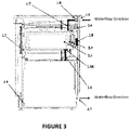
- FIGURE 3
- illustrates the mains water flow path in the inventive heat recovery oven with dishwasher.
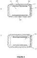
- FIGURE 4
- illustrates the structural alternatives of the oven firebox and water tank peripheral to the oven; A) the state in which the oven firebox wall also functions as the inner wall of the water tank, B) the state where the water tank body comprises a separate body and is installed within the oven firebox.
- To provide a better understanding of the inventive heat recovery oven with dishwasher, parts, and sections given in the figures are enumerated, and the numbers corresponding to each part and section are provided below;
- 1) Carrier Body
- 1.1) Control Panel
- 1.2) Upper Sheet
- 1.3) Side Sheet
- 1.4) Kickplate
- 1.5) Feet
- 1.6) Water Transfer Hose Between the Oven and Dishwasher
- 1.7) Mains Water Inlet Hose
- 1.8) Mains Water Inlet Solenoid Valve (Electric Valve)
- 1.9) Mains Water Inlet Port
- 2) Oven Section
- 2.1) Oven Handle
- 2.2) Oven Door
- 2.3) Oven Firebox
- 2.4) Water Tank
- 2.5) Oven Door Joint
- 2.6) Cooling Fan
- 2.7) Oven Door Hinge
- 2.8) Turbo Fan
- 2.9) Water Tank Temperature Sensor
- 2.10) Oven Upper Resistance
- 2.11) Oven Insulation Material
- 2.12) Water Level Sensor
- 2.13) Oven Lower Resistance
- 2.14) Water Tank Water Outlet Solenoid Valve
- 3) Dishwasher Section
- 3.1) Dishwasher Handle
- 3.2) Dishwasher Door
- 3.3) Dishwasher Boiler
- 3.4) Dishwasher Basket
- 3.5) Dishwasher Water Temperature Sensor
- 3.6) Dishwasher Door Hinge
- 3.7) Water Discharge Opening
- The present invention relates to a heat recovery oven with dishwasher that is capable of performing the functions of dishwashing and cooking in two separate sections within a single structure. Heat recovery oven with dishwasher has two separate doors for these two functions (
Figure 1 ) and these two functions can be operated at the same time or at different times. The cooking function of the oven section (2) and the dishwashing function of the dishwasher section (3) can operate independently at different times, can also operate independently at the same time, or the dishwashing function can operate in the dishwasher section (3) immediately after the cooking function in the oven section (2) relevant with each other in the economic function. - In the present invention, while the cooking function continues or the cooking function is completed, the waste heat generated in the oven firebox (2.3) is used in the dishwasher section (3). The water received from the mains is used for the dishwashing function in the dishwasher section (3) when it is heated by the waste heat above the oven firebox (2.3) and is adjusted to the required temperature. The mains water let into the water chamber (2.4) absorbs the heat in the oven firebox (2.3) after the cooking function in the oven section (2), the oven is cooled rapidly and the ambient temperature is prevented from rising uncomfortably. Moreover, energy saving is also achieved since the water heated by the waste heat is used in the dishwasher section (3).
- The carrier body (1) of said heat recovery oven with dishwasher comprises two main sections; these are the oven section (2) and the dishwasher section (3). Moreover, a central control panel (1.1) is provided within the carrier body (1), and the oven section (2) and the dishwasher section (3) are controlled from this panel. Carrier body (1) of the heat recovery oven with dishwasher comprises two separate doors as the oven door (2.2) and the dishwasher door (3.2) for the oven section (2) and the dishwasher section (3), external body sheets as the upper sheet (1.2) and the side sheet (1.3), and feet (1.5). The oven section (2) where the cooking function is carried out comprises the oven firebox (2.3), a cooling fan (2.6), a turbo fan (2.8), wire racks, trays, a lighting lamp, the safety thermostat, oven upper resistance (2.10), oven lower resistance (2.13), a water tank (2.4) located around the oven firebox (2.3), a water level sensor (2.12) that measures the amount of water let into the water tank, a temperature sensor (2.9), a solenoid valve (2.14) (electric valve) to direct the water to the dishwasher after the water is heated. A water transfer hose (1.6) is provided between the oven and dishwasher between two sections. The dishwasher section (3), where the dishwashing function is performed, comprises the dishwasher boiler (3.3), resistances, the dishwasher basket (3.4), water pump, water spray propeller, water drain filter, wastewater hose, detergent compartment, dishwasher water temperature sensor (3.5), water level meter, dishwasher boiler (3.3), water tank, mains water inlet, temperature sensor, solenoid valve (2.14), water level sensor (2.12), upper water spray propeller, lower water spray propeller.
- In the inventive heat recovery oven with dishwasher, the oven and dishwasher sections can operate simultaneously. However, the dishwashing cycle is preferably carried out in the dishwasher section right after the cooking cycle in the oven section so as to achieve the highest efficiency.
- The operating method of the heat recovery oven with dishwasher in which the dishwashing cycle is commenced right after the cooking cycle so as to achieve high efficiency comprises the following process steps;
- i. commencing the cooking cycle in the oven section by initializing said high-efficiency cycle from the control panel (1.1),
- ii. starting to draw water from the mains water by opening mains water inlet solenoid valve (1.8) that controls the water coming from the mains water inlet (1.9) for the dishwasher washing function immediately after the cooking cycle in the oven section is completed,
- iii. transferring the mains water to the water tank (2.4) located around the oven firebox (2.3),
- iv. measuring the temperature of the water tank (2.4) with the temperature sensor (2.9) and transferring the temperature information to the control card,
- v. heating the water in the water tank (2.4) by the oven firebox waste heat in the water tank (2.4) until it reaches the desired temperature for the dishwashing cycle in the dishwasher section,
- vi.
- a) transferring the water heated in the water tank (2.4) to the dishwasher boiler (3.3) by triggering the solenoid valve (2.14) by the card according to the data transmitted by the temperature sensor (2.9) and by opening the solenoid valve (2.14) in case the water heated with the waste heat of the oven firebox reaches the temperature required by the washing program selected by the user, or
- b) transferring the water to the dishwasher boiler (3.3) after the solenoid valve (2.14) is opened by the card after the control card detects that the water temperature cannot rise more by means of the temperature sensor (2.9) and the card detects that the oven firebox (2.3) does not heat the water anymore in case the water heated with the waste heat of the oven firebox reaches the temperature required by the washing program selected by the user;
- vii. heating the water by means of the resistance in case the water temperature in the dishwasher boiler (3.3) is measured by the temperature sensor (3.5) and used directly in the dishwashing process or in case the water does not meet the temperature required by the washing program selected by the user,
- viii. starting the dishwashing cycle in the dishwasher section and washing the dishes by spraying the water with detergent for a certain time and temperature on the dishes,
- ix. draining the wastewater in the dishwasher boiler (3.3) through the wastewater discharge opening (3.7) when washing is completed and turning off the device when the dishwashing cycle is completed.
- The body of the inventive heat recovery oven with dishwasher comprises an insulation material (2.11) located around the oven firebox (2.3). The water tank (2.4) is positioned between the oven firebox (2.3) and the insulation material (2.11).
- In an embodiment of the present invention, the water tank (2.4) and the oven firebox (2.3) consist of separate parts. The water tank (2.4) is in contact with the oven firebox (2.3) (
Figure 4-B ) and it features high thermal conductivity and a water-resistant structure that allows heat transfer. The water tank (2.4) is preferably made of stainless steel. The water tank (2.4) that is in contact with the oven firebox (2.3) is positioned between the oven firebox (2.3) and the insulation material (2.11). The insulation material (2.11) can be an insulation blanket made of rock wool or a similar material. - In another embodiment of the present invention, the water tank (2.3) and the oven firebox (2.4) consist of a single part (
Figure 4-A ). The mains water let into the water tank (2.4) passes directly through the body of the oven firebox (2.3). Since there is no separate wall between them, a much more efficient heat transfer is achieved. Water directly comes into contact with the body of the oven firebox (2.3) where there is waste heat of the oven firebox and receives the waste heat. During the cooking phase, the water tank (2.4) is always empty and the water tank (2.4) serves as an insulator by providing heat insulation by means of the air space within the same. In this configuration; after the cooking cycle in the oven is complete and the washing cycle in the dishwasher begins, the water to be used in the dishwasher is filled into the water tank (2.4). The water filling the water tank (2.4) is heated by being fed through the waste heat of the oven. At this stage, the water temperature in the water tank is measured by the temperature sensor (2.9) and transferred to the dishwasher. If the temperature of the water is lower than the desired value, it is heated by the resistance of the dishwasher, and the dishwashing cycle is started. - The dishwasher washing program is selected by the user at the beginning of the high-efficiency cycle via the control panel (1.1). Each program has different temperature settings. For example; in economic programs, dishes are washed at a temperature between 45-50 °C, and in the intensive programs, they are washed at a temperature between 60-75 °C.
Claims (9)
- A heat recovery oven with dishwasher comprising:- a carrier body (1) that contains two separate doors, namely, the oven door (2.2) and the dishwasher door (3.2), external body sheets, namely, the upper sheet (1.2) and the side sheet (1.3), and feet (1.5),- an oven section (2) in which the cooking function is performed and that contains oven firebox (2.3), cooling fan (2.6), turbo fan (2.8), wire racks, trays, lighting lamp, safety thermostat, oven upper resistance (2.10), oven lower resistance (2.13), a water tank (2.4) a water level sensor (2.12) that measures the amount of water taken into the water tank, a temperature sensor (2.9), an electric solenoid valve (2.14) to direct the water to the dishwasher after the water is heated,- a dishwasher section (3) in which the dishwashing function is performed and that contains dishwasher boiler (3.3), resistances, water transfer hose between the oven and dishwasher (1.6), dishwasher basket (3.4), water pump, water spray propeller, water drain filter, wastewater hose, detergent compartment, dishwasher water temperature sensor (3.5), water level meter, water tank, mains water inlet, temperature sensor, solenoid valve (2.14), water level sensor (2.12), upper water spray propeller, lower water spray propeller; the heat recovery oven with dishwasher is characterized in that the water tank (2.4) is located around the oven firebox (2.3).
- A heat recovery oven with dishwasher according to Claim 1, characterized in that; an insulation material (2.11) is positioned around the oven firebox (2.3).
- A heat recovery oven with dishwasher according to Claim 2, characterized in that; the water tank (2.4) is located between the oven firebox (2.3) and the insulation material (2.11).
- A heat recovery oven with dishwasher according to Claim 1, characterized in that; the water tank (2.4) and the oven firebox (2.3) consist of separate parts.
- A heat recovery oven with dishwasher according to Claim 4, characterized in that; the water tank (2.4) is made of stainless steel.
- A heat recovery oven with dishwasher according to Claim 1, characterized in that; the water tank (2.4) and the oven firebox (2.3) consist of a single part.
- A heat recovery oven with dishwasher according to Claim 6, characterized in that; the water tank (2.4) and the oven firebox (2.3) consisting of one piece are made of stainless steel.
- A heat recovery oven with dishwasher according to any of the preceding claims, characterized in that; the cooking function in the oven section (2) and the dishwashing function in the dishwasher section (3) can be carried out at the same time or at different times independently of one another.
- A method for operating the heat recovery oven with dishwasher according to any of the preceding claims, in which the dishwashing cycle is commenced right after the cooking cycle so as to achieve high efficiency, characterized in that, it comprises the process steps of;i. commencing the cooking cycle in the oven section by initializing said high-efficiency cycle from the control panel (1.1),ii. starting to draw water from the mains water by opening mains water inlet solenoid valve (1.8) that controls the water coming from the mains water inlet (1.9) for the dishwasher washing function immediately after the cooking cycle in the oven section is completed,iii. transferring the mains water to the water tank (2.4) located around the oven firebox (2.3),iv. measuring the temperature of the water tank (2.4) with the temperature sensor (2.9) and transferring the temperature information to the control card,v. heating the water in the water tank (2.4) by the waste heat of the oven firebox in the water tank (2.4) until it reaches the desired temperature for the dishwashing cycle in the dishwasher section,vi.a) transferring the water heated in the water tank (2.4) to the dishwasher boiler (3.3) by triggering the solenoid valve (2.14) by the card according to the data transmitted by the temperature sensor (2.9) and by opening the solenoid valve (2.14) in case the water heated with the waste heat of the oven firebox reaches the temperature required by the washing program selected by the user, orb) transferring the water to the dishwasher boiler (3.3) after the solenoid valve (2.14) is opened by the card after the control card detects that the water temperature cannot rise more by means of the temperature sensor (2.9) and the card detects that the oven firebox (2.3) does not heat the water anymore in case the water heated with the waste heat of the oven firebox reaches the temperature required by the washing program selected by the user;vii. heating the water with the resistance in case the water temperature in the dishwasher boiler (3.3) is measured by the water temperature sensor (3.5) and used directly in the dishwashing process or the water does not meet the temperature required by the washing program selected by the user,viii. commencing the dishwashing cycle in the dishwasher section and washing the dishes by spraying the water with detergent for a certain time and temperature on the dishes,ix. draining the wastewater in the dishwasher boiler (3.3) through the wastewater discharge opening (3.7) when the washing cycle is complete and turning off the device when the dishwashing cycle is complete.
Applications Claiming Priority (1)
| Application Number | Priority Date | Filing Date | Title |
|---|---|---|---|
| TR2020/02395A TR202002395A1 (en) | 2020-02-17 | 2020-02-17 | Oven with heat recovery dishwasher. |
Publications (2)
| Publication Number | Publication Date |
|---|---|
| EP3865042A1 EP3865042A1 (en) | 2021-08-18 |
| EP3865042B1 true EP3865042B1 (en) | 2022-04-27 |
Family
ID=74853506
Family Applications (1)
| Application Number | Title | Priority Date | Filing Date |
|---|---|---|---|
| EP21157704.4A Active EP3865042B1 (en) | 2020-02-17 | 2021-02-17 | Heat recovery oven with dishwasher |
Country Status (3)
| Country | Link |
|---|---|
| EP (1) | EP3865042B1 (en) |
| ES (1) | ES2920289T3 (en) |
| TR (1) | TR202002395A1 (en) |
Families Citing this family (2)
| Publication number | Priority date | Publication date | Assignee | Title |
|---|---|---|---|---|
| IT202200007406A1 (en) | 2022-04-13 | 2023-10-13 | S P M Eng S R L | HOUSEHOLD APPLIANCE FOR SELECTIVELY COOKING FOOD OR WASHING DISHES |
| CN114947559A (en) * | 2022-06-01 | 2022-08-30 | 嵊州市浙江工业大学创新研究院 | Integrated in-stove electric oven with waste heat collection device and waste heat collection heat exchange method |
Family Cites Families (6)
| Publication number | Priority date | Publication date | Assignee | Title |
|---|---|---|---|---|
| DE3843039A1 (en) * | 1988-12-21 | 1990-06-28 | Bosch Siemens Hausgeraete | HOUSEHOLD APPLIANCE |
| DE3843040A1 (en) * | 1988-12-21 | 1990-06-28 | Bosch Siemens Hausgeraete | COMBINED HOUSEHOLD APPLIANCE FOR A COMPACT KITCHEN CENTER |
| GB2381442A (en) | 2001-11-03 | 2003-05-07 | Christopher Bridges | Combined oven and dishwasher using a single chamber for both functions |
| CN2772495Y (en) | 2004-12-09 | 2006-04-19 | 白长发 | Beauty trolley structure with face steaming device |
| EP2412287A1 (en) | 2008-12-12 | 2012-02-01 | Electrolux Home Products Corporation N.V. | A system with at least two household appliances and procedure |
| DE102012109153A1 (en) * | 2012-09-27 | 2014-04-17 | Miele & Cie. Kg | Household appliance arrangement has two household appliances and heat transmission device to transmit portion of thermal energy available in former household appliance selectively to latter household appliance |
-
2020
- 2020-02-17 TR TR2020/02395A patent/TR202002395A1/en unknown
-
2021
- 2021-02-17 EP EP21157704.4A patent/EP3865042B1/en active Active
- 2021-02-17 ES ES21157704T patent/ES2920289T3/en active Active
Also Published As
| Publication number | Publication date |
|---|---|
| TR202002395A1 (en) | 2021-08-23 |
| ES2920289T3 (en) | 2022-08-02 |
| EP3865042A1 (en) | 2021-08-18 |
Similar Documents
| Publication | Publication Date | Title |
|---|---|---|
| CN201847449U (en) | Reservation cooking machine | |
| CN102415810A (en) | Ordered cooking machine | |
| EP3865042A1 (en) | Heat recovery oven with dishwasher | |
| CN201977552U (en) | Reserving cooker | |
| CN105615607A (en) | Meal-cooking machine capable of reducing steam discharge | |
| CN108567313A (en) | Cooking control method and cooking apparatus for cooking apparatus | |
| CN211380786U (en) | Long-time reservation cooking machine integrated with integrated cooker | |
| CN101433429B (en) | Energy-saving multifunctional integral kitchen tool | |
| CN201977553U (en) | Reserving cooking machine | |
| CN201299073Y (en) | Multifunctional food processing machine | |
| JP5362267B2 (en) | Waste heat utilization system for commercial kitchen | |
| CN103720344A (en) | Steam heating furnace | |
| CN102551517A (en) | Advance cooking machine | |
| CN102226540B (en) | Chinese food kitchen apparatus with zero energy consumption | |
| CN216346444U (en) | Energy-saving gas range for stir-frying Chinese food | |
| CN103948298B (en) | Electric heating and heat-accumulating tank | |
| CN204218630U (en) | A kind of emissions reduction steam boil rice and dish cooker | |
| CN206094214U (en) | Fry stove heating device | |
| GB2381442A (en) | Combined oven and dishwasher using a single chamber for both functions | |
| CN213721490U (en) | Intelligent electric energy water vapor cooker with saturated steam and superheated steam | |
| CN201929690U (en) | Cooking device | |
| CN201462930U (en) | Multifunctional high-efficiency energy-saving coal-fired cooking machine set | |
| CN221533475U (en) | Quick heating electric cooker | |
| CN217610499U (en) | Portable cooking and steaming device | |
| CN201977527U (en) | Conservation food boiler |
Legal Events
| Date | Code | Title | Description |
|---|---|---|---|
| PUAI | Public reference made under article 153(3) epc to a published international application that has entered the european phase |
Free format text: ORIGINAL CODE: 0009012 |
|
| STAA | Information on the status of an ep patent application or granted ep patent |
Free format text: STATUS: THE APPLICATION HAS BEEN PUBLISHED |
|
| AK | Designated contracting states |
Kind code of ref document: A1 Designated state(s): AL AT BE BG CH CY CZ DE DK EE ES FI FR GB GR HR HU IE IS IT LI LT LU LV MC MK MT NL NO PL PT RO RS SE SI SK SM TR |
|
| STAA | Information on the status of an ep patent application or granted ep patent |
Free format text: STATUS: REQUEST FOR EXAMINATION WAS MADE |
|
| 17P | Request for examination filed |
Effective date: 20211103 |
|
| RBV | Designated contracting states (corrected) |
Designated state(s): AL AT BE BG CH CY CZ DE DK EE ES FI FR GB GR HR HU IE IS IT LI LT LU LV MC MK MT NL NO PL PT RO RS SE SI SK SM TR |
|
| RIC1 | Information provided on ipc code assigned before grant |
Ipc: F24C 15/18 20060101ALN20211223BHEP Ipc: A47L 15/42 20060101ALN20211223BHEP Ipc: F24C 15/32 20060101ALI20211223BHEP Ipc: F24C 13/00 20060101ALI20211223BHEP Ipc: A47L 15/00 20060101AFI20211223BHEP |
|
| GRAP | Despatch of communication of intention to grant a patent |
Free format text: ORIGINAL CODE: EPIDOSNIGR1 |
|
| STAA | Information on the status of an ep patent application or granted ep patent |
Free format text: STATUS: GRANT OF PATENT IS INTENDED |
|
| RIC1 | Information provided on ipc code assigned before grant |
Ipc: F24C 15/18 20060101ALN20220125BHEP Ipc: A47L 15/42 20060101ALN20220125BHEP Ipc: F24C 15/32 20060101ALI20220125BHEP Ipc: F24C 13/00 20060101ALI20220125BHEP Ipc: A47L 15/00 20060101AFI20220125BHEP |
|
| GRAS | Grant fee paid |
Free format text: ORIGINAL CODE: EPIDOSNIGR3 |
|
| INTG | Intention to grant announced |
Effective date: 20220217 |
|
| GRAA | (expected) grant |
Free format text: ORIGINAL CODE: 0009210 |
|
| STAA | Information on the status of an ep patent application or granted ep patent |
Free format text: STATUS: THE PATENT HAS BEEN GRANTED |
|
| AK | Designated contracting states |
Kind code of ref document: B1 Designated state(s): AL AT BE BG CH CY CZ DE DK EE ES FI FR GB GR HR HU IE IS IT LI LT LU LV MC MK MT NL NO PL PT RO RS SE SI SK SM TR |
|
| REG | Reference to a national code |
Ref country code: GB Ref legal event code: FG4D |
|
| REG | Reference to a national code |
Ref country code: CH Ref legal event code: EP |
|
| REG | Reference to a national code |
Ref country code: DE Ref legal event code: R096 Ref document number: 602021000067 Country of ref document: DE |
|
| REG | Reference to a national code |
Ref country code: AT Ref legal event code: REF Ref document number: 1486277 Country of ref document: AT Kind code of ref document: T Effective date: 20220515 |
|
| REG | Reference to a national code |
Ref country code: IE Ref legal event code: FG4D |
|
| REG | Reference to a national code |
Ref country code: ES Ref legal event code: FG2A Ref document number: 2920289 Country of ref document: ES Kind code of ref document: T3 Effective date: 20220802 |
|
| REG | Reference to a national code |
Ref country code: LT Ref legal event code: MG9D |
|
| REG | Reference to a national code |
Ref country code: NL Ref legal event code: MP Effective date: 20220427 |
|
| REG | Reference to a national code |
Ref country code: AT Ref legal event code: MK05 Ref document number: 1486277 Country of ref document: AT Kind code of ref document: T Effective date: 20220427 |
|
| PG25 | Lapsed in a contracting state [announced via postgrant information from national office to epo] |
Ref country code: NL Free format text: LAPSE BECAUSE OF FAILURE TO SUBMIT A TRANSLATION OF THE DESCRIPTION OR TO PAY THE FEE WITHIN THE PRESCRIBED TIME-LIMIT Effective date: 20220427 |
|
| PG25 | Lapsed in a contracting state [announced via postgrant information from national office to epo] |
Ref country code: SE Free format text: LAPSE BECAUSE OF FAILURE TO SUBMIT A TRANSLATION OF THE DESCRIPTION OR TO PAY THE FEE WITHIN THE PRESCRIBED TIME-LIMIT Effective date: 20220427 Ref country code: PT Free format text: LAPSE BECAUSE OF FAILURE TO SUBMIT A TRANSLATION OF THE DESCRIPTION OR TO PAY THE FEE WITHIN THE PRESCRIBED TIME-LIMIT Effective date: 20220829 Ref country code: NO Free format text: LAPSE BECAUSE OF FAILURE TO SUBMIT A TRANSLATION OF THE DESCRIPTION OR TO PAY THE FEE WITHIN THE PRESCRIBED TIME-LIMIT Effective date: 20220727 Ref country code: LT Free format text: LAPSE BECAUSE OF FAILURE TO SUBMIT A TRANSLATION OF THE DESCRIPTION OR TO PAY THE FEE WITHIN THE PRESCRIBED TIME-LIMIT Effective date: 20220427 Ref country code: HR Free format text: LAPSE BECAUSE OF FAILURE TO SUBMIT A TRANSLATION OF THE DESCRIPTION OR TO PAY THE FEE WITHIN THE PRESCRIBED TIME-LIMIT Effective date: 20220427 Ref country code: GR Free format text: LAPSE BECAUSE OF FAILURE TO SUBMIT A TRANSLATION OF THE DESCRIPTION OR TO PAY THE FEE WITHIN THE PRESCRIBED TIME-LIMIT Effective date: 20220728 Ref country code: FI Free format text: LAPSE BECAUSE OF FAILURE TO SUBMIT A TRANSLATION OF THE DESCRIPTION OR TO PAY THE FEE WITHIN THE PRESCRIBED TIME-LIMIT Effective date: 20220427 Ref country code: BG Free format text: LAPSE BECAUSE OF FAILURE TO SUBMIT A TRANSLATION OF THE DESCRIPTION OR TO PAY THE FEE WITHIN THE PRESCRIBED TIME-LIMIT Effective date: 20220727 Ref country code: AT Free format text: LAPSE BECAUSE OF FAILURE TO SUBMIT A TRANSLATION OF THE DESCRIPTION OR TO PAY THE FEE WITHIN THE PRESCRIBED TIME-LIMIT Effective date: 20220427 |
|
| PG25 | Lapsed in a contracting state [announced via postgrant information from national office to epo] |
Ref country code: RS Free format text: LAPSE BECAUSE OF FAILURE TO SUBMIT A TRANSLATION OF THE DESCRIPTION OR TO PAY THE FEE WITHIN THE PRESCRIBED TIME-LIMIT Effective date: 20220427 Ref country code: PL Free format text: LAPSE BECAUSE OF FAILURE TO SUBMIT A TRANSLATION OF THE DESCRIPTION OR TO PAY THE FEE WITHIN THE PRESCRIBED TIME-LIMIT Effective date: 20220427 Ref country code: LV Free format text: LAPSE BECAUSE OF FAILURE TO SUBMIT A TRANSLATION OF THE DESCRIPTION OR TO PAY THE FEE WITHIN THE PRESCRIBED TIME-LIMIT Effective date: 20220427 Ref country code: IS Free format text: LAPSE BECAUSE OF FAILURE TO SUBMIT A TRANSLATION OF THE DESCRIPTION OR TO PAY THE FEE WITHIN THE PRESCRIBED TIME-LIMIT Effective date: 20220827 |
|
| REG | Reference to a national code |
Ref country code: DE Ref legal event code: R097 Ref document number: 602021000067 Country of ref document: DE |
|
| PG25 | Lapsed in a contracting state [announced via postgrant information from national office to epo] |
Ref country code: SM Free format text: LAPSE BECAUSE OF FAILURE TO SUBMIT A TRANSLATION OF THE DESCRIPTION OR TO PAY THE FEE WITHIN THE PRESCRIBED TIME-LIMIT Effective date: 20220427 Ref country code: SK Free format text: LAPSE BECAUSE OF FAILURE TO SUBMIT A TRANSLATION OF THE DESCRIPTION OR TO PAY THE FEE WITHIN THE PRESCRIBED TIME-LIMIT Effective date: 20220427 Ref country code: RO Free format text: LAPSE BECAUSE OF FAILURE TO SUBMIT A TRANSLATION OF THE DESCRIPTION OR TO PAY THE FEE WITHIN THE PRESCRIBED TIME-LIMIT Effective date: 20220427 Ref country code: EE Free format text: LAPSE BECAUSE OF FAILURE TO SUBMIT A TRANSLATION OF THE DESCRIPTION OR TO PAY THE FEE WITHIN THE PRESCRIBED TIME-LIMIT Effective date: 20220427 Ref country code: DK Free format text: LAPSE BECAUSE OF FAILURE TO SUBMIT A TRANSLATION OF THE DESCRIPTION OR TO PAY THE FEE WITHIN THE PRESCRIBED TIME-LIMIT Effective date: 20220427 Ref country code: CZ Free format text: LAPSE BECAUSE OF FAILURE TO SUBMIT A TRANSLATION OF THE DESCRIPTION OR TO PAY THE FEE WITHIN THE PRESCRIBED TIME-LIMIT Effective date: 20220427 |
|
| PLBE | No opposition filed within time limit |
Free format text: ORIGINAL CODE: 0009261 |
|
| STAA | Information on the status of an ep patent application or granted ep patent |
Free format text: STATUS: NO OPPOSITION FILED WITHIN TIME LIMIT |
|
| PG25 | Lapsed in a contracting state [announced via postgrant information from national office to epo] |
Ref country code: AL Free format text: LAPSE BECAUSE OF FAILURE TO SUBMIT A TRANSLATION OF THE DESCRIPTION OR TO PAY THE FEE WITHIN THE PRESCRIBED TIME-LIMIT Effective date: 20220427 |
|
| 26N | No opposition filed |
Effective date: 20230130 |
|
| PG25 | Lapsed in a contracting state [announced via postgrant information from national office to epo] |
Ref country code: MC Free format text: LAPSE BECAUSE OF FAILURE TO SUBMIT A TRANSLATION OF THE DESCRIPTION OR TO PAY THE FEE WITHIN THE PRESCRIBED TIME-LIMIT Effective date: 20220427 |
|
| REG | Reference to a national code |
Ref country code: BE Ref legal event code: MM Effective date: 20230228 |
|
| PG25 | Lapsed in a contracting state [announced via postgrant information from national office to epo] |
Ref country code: LU Free format text: LAPSE BECAUSE OF NON-PAYMENT OF DUE FEES Effective date: 20230217 |
|
| REG | Reference to a national code |
Ref country code: IE Ref legal event code: MM4A |
|
| PG25 | Lapsed in a contracting state [announced via postgrant information from national office to epo] |
Ref country code: IE Free format text: LAPSE BECAUSE OF NON-PAYMENT OF DUE FEES Effective date: 20230217 |
|
| PG25 | Lapsed in a contracting state [announced via postgrant information from national office to epo] |
Ref country code: BE Free format text: LAPSE BECAUSE OF NON-PAYMENT OF DUE FEES Effective date: 20230228 |
|
| PGFP | Annual fee paid to national office [announced via postgrant information from national office to epo] |
Ref country code: ES Payment date: 20240301 Year of fee payment: 4 |
|
| PGFP | Annual fee paid to national office [announced via postgrant information from national office to epo] |
Ref country code: DE Payment date: 20240226 Year of fee payment: 4 |
|
| PGFP | Annual fee paid to national office [announced via postgrant information from national office to epo] |
Ref country code: IT Payment date: 20240229 Year of fee payment: 4 Ref country code: FR Payment date: 20240118 Year of fee payment: 4 |
|
| REG | Reference to a national code |
Ref country code: CH Ref legal event code: PL |
|
| PG25 | Lapsed in a contracting state [announced via postgrant information from national office to epo] |
Ref country code: CH Free format text: LAPSE BECAUSE OF NON-PAYMENT OF DUE FEES Effective date: 20240229 |
|
| PG25 | Lapsed in a contracting state [announced via postgrant information from national office to epo] |
Ref country code: CH Free format text: LAPSE BECAUSE OF NON-PAYMENT OF DUE FEES Effective date: 20240229 |
|
| PG25 | Lapsed in a contracting state [announced via postgrant information from national office to epo] |
Ref country code: BG Free format text: LAPSE BECAUSE OF FAILURE TO SUBMIT A TRANSLATION OF THE DESCRIPTION OR TO PAY THE FEE WITHIN THE PRESCRIBED TIME-LIMIT Effective date: 20220427 |
|
| PG25 | Lapsed in a contracting state [announced via postgrant information from national office to epo] |
Ref country code: BG Free format text: LAPSE BECAUSE OF FAILURE TO SUBMIT A TRANSLATION OF THE DESCRIPTION OR TO PAY THE FEE WITHIN THE PRESCRIBED TIME-LIMIT Effective date: 20220427 |
|
| PG25 | Lapsed in a contracting state [announced via postgrant information from national office to epo] |
Ref country code: CY Free format text: LAPSE BECAUSE OF FAILURE TO SUBMIT A TRANSLATION OF THE DESCRIPTION OR TO PAY THE FEE WITHIN THE PRESCRIBED TIME-LIMIT; INVALID AB INITIO Effective date: 20210217 |
|
| PG25 | Lapsed in a contracting state [announced via postgrant information from national office to epo] |
Ref country code: HU Free format text: LAPSE BECAUSE OF FAILURE TO SUBMIT A TRANSLATION OF THE DESCRIPTION OR TO PAY THE FEE WITHIN THE PRESCRIBED TIME-LIMIT; INVALID AB INITIO Effective date: 20210217 |
|
| REG | Reference to a national code |
Ref country code: DE Ref legal event code: R119 Ref document number: 602021000067 Country of ref document: DE |
|
| GBPC | Gb: european patent ceased through non-payment of renewal fee |
Effective date: 20250217 |
|
| PG25 | Lapsed in a contracting state [announced via postgrant information from national office to epo] |
Ref country code: TR Free format text: LAPSE BECAUSE OF FAILURE TO SUBMIT A TRANSLATION OF THE DESCRIPTION OR TO PAY THE FEE WITHIN THE PRESCRIBED TIME-LIMIT Effective date: 20220427 |
|
| PG25 | Lapsed in a contracting state [announced via postgrant information from national office to epo] |
Ref country code: DE Free format text: LAPSE BECAUSE OF NON-PAYMENT OF DUE FEES Effective date: 20250902 |
|
| PG25 | Lapsed in a contracting state [announced via postgrant information from national office to epo] |
Ref country code: GB Free format text: LAPSE BECAUSE OF NON-PAYMENT OF DUE FEES Effective date: 20250217 |
|
| PG25 | Lapsed in a contracting state [announced via postgrant information from national office to epo] |
Ref country code: FR Free format text: LAPSE BECAUSE OF NON-PAYMENT OF DUE FEES Effective date: 20250228 Ref country code: IT Free format text: LAPSE BECAUSE OF NON-PAYMENT OF DUE FEES Effective date: 20250217 |
|
| PG25 | Lapsed in a contracting state [announced via postgrant information from national office to epo] |
Ref country code: SI Free format text: LAPSE BECAUSE OF FAILURE TO SUBMIT A TRANSLATION OF THE DESCRIPTION OR TO PAY THE FEE WITHIN THE PRESCRIBED TIME-LIMIT Effective date: 20220427 |
|
| REG | Reference to a national code |
Ref country code: ES Ref legal event code: FD2A Effective date: 20260326 |
|
| PG25 | Lapsed in a contracting state [announced via postgrant information from national office to epo] |
Ref country code: ES Free format text: LAPSE BECAUSE OF NON-PAYMENT OF DUE FEES Effective date: 20250218 |