EP3863494B1 - Dish washing appliance with retracting dishwasher rack system, and method of allowing height adjustment - Google Patents
Dish washing appliance with retracting dishwasher rack system, and method of allowing height adjustment Download PDFInfo
- Publication number
- EP3863494B1 EP3863494B1 EP19896098.1A EP19896098A EP3863494B1 EP 3863494 B1 EP3863494 B1 EP 3863494B1 EP 19896098 A EP19896098 A EP 19896098A EP 3863494 B1 EP3863494 B1 EP 3863494B1
- Authority
- EP
- European Patent Office
- Prior art keywords
- dishwasher
- rack
- height
- tub
- dishwasher rack
- Prior art date
- Legal status (The legal status is an assumption and is not a legal conclusion. Google has not performed a legal analysis and makes no representation as to the accuracy of the status listed.)
- Active
Links
Images



Classifications
-
- A—HUMAN NECESSITIES
- A47—FURNITURE; DOMESTIC ARTICLES OR APPLIANCES; COFFEE MILLS; SPICE MILLS; SUCTION CLEANERS IN GENERAL
- A47L—DOMESTIC WASHING OR CLEANING; SUCTION CLEANERS IN GENERAL
- A47L15/00—Washing or rinsing machines for crockery or tableware
- A47L15/42—Details
- A47L15/50—Racks ; Baskets
- A47L15/504—Arrangements for changing the height of racks
-
- A—HUMAN NECESSITIES
- A47—FURNITURE; DOMESTIC ARTICLES OR APPLIANCES; COFFEE MILLS; SPICE MILLS; SUCTION CLEANERS IN GENERAL
- A47L—DOMESTIC WASHING OR CLEANING; SUCTION CLEANERS IN GENERAL
- A47L15/00—Washing or rinsing machines for crockery or tableware
- A47L15/42—Details
- A47L15/50—Racks ; Baskets
- A47L15/507—Arrangements for extracting racks, e.g. roller supports
-
- A—HUMAN NECESSITIES
- A47—FURNITURE; DOMESTIC ARTICLES OR APPLIANCES; COFFEE MILLS; SPICE MILLS; SUCTION CLEANERS IN GENERAL
- A47L—DOMESTIC WASHING OR CLEANING; SUCTION CLEANERS IN GENERAL
- A47L15/00—Washing or rinsing machines for crockery or tableware
- A47L15/0018—Controlling processes, i.e. processes to control the operation of the machine characterised by the purpose or target of the control
- A47L15/0049—Detection or prevention of malfunction, including accident prevention
-
- A—HUMAN NECESSITIES
- A47—FURNITURE; DOMESTIC ARTICLES OR APPLIANCES; COFFEE MILLS; SPICE MILLS; SUCTION CLEANERS IN GENERAL
- A47L—DOMESTIC WASHING OR CLEANING; SUCTION CLEANERS IN GENERAL
- A47L15/00—Washing or rinsing machines for crockery or tableware
- A47L15/42—Details
- A47L15/4251—Details of the casing
- A47L15/4257—Details of the loading door
- A47L15/4259—Arrangements of locking or security/safety devices for doors, e.g. door latches, switch to stop operation when door is open
-
- A—HUMAN NECESSITIES
- A47—FURNITURE; DOMESTIC ARTICLES OR APPLIANCES; COFFEE MILLS; SPICE MILLS; SUCTION CLEANERS IN GENERAL
- A47L—DOMESTIC WASHING OR CLEANING; SUCTION CLEANERS IN GENERAL
- A47L15/00—Washing or rinsing machines for crockery or tableware
- A47L15/42—Details
- A47L15/50—Racks ; Baskets
- A47L15/506—Arrangements for lifting racks for loading or unloading purposes
Definitions
- the torsion spring 30 winds up thereby increasing the tension force or stored energy. It should be understood, the counter rotation of the shaft or axle 51 and/or pinion gear 52 may correspondingly reduce the tension force in some embodiments.
Landscapes
- Washing And Drying Of Tableware (AREA)
Description
- The present invention relates to a dish washing appliance with a dishwasher rack.
- Typical dishwasher racks are pulled out and pushed back into place within the dishwasher tub, with the rack riding on rollers, wheels, glides, or rails. Occasionally, these racks are motorized to translate the movement of the dishwasher rack. However, this practice often may be expensive to implement, and the environment (e.g. heat, cold, moisture, etc.) of the dishwasher tub may create a variety of challenges. Thus, there is a need for the dishwasher rack to be capable of retracting into the dishwasher tub with minimal or no motorization.
US 2010/051067 A1 discusses an assisted-movement system for one of a rack and a door of an appliance, such as a dishwasher.US 2018/177378 A1 discusses a dishwasher rack lift system.DE 102013222576 A1 discusses a household appliance such as a dishwasher with a loading level that is displaceable and a retraction device.US 3736037 A discusses a rack level adjustment apparatus in an appliance cabinet such as a dishwasher cabinet. - In accordance with the present invention, there is provided a dish washing appliance as recited by
claim 1, along with a method of allowing height adjustment of a retracting dishwasher rack within a dish washing appliance as recited by claim 7. Preferred features are set out in the dependent claims. In the following, each of the described methods, apparatuses, embodiments, examples, and aspects, which do not fully correspond to the invention as defined in the claims is thus not according to the invention and is, as well as the whole following description, present for illustration purposes only or to highlight specific aspects or features of the claims. Embodiments not falling under the scope of the claims should be interpreted as examples useful for understanding the invention. - These and other advantages and features, which characterize the embodiments, are set forth in the claims annexed hereto and form a further part hereof. However, for a better understanding of the embodiments, and of the advantages and objectives attained through its use, reference should be made to the drawings and to the accompanying descriptive matter, in which there are described example embodiments.
- In the drawings, like reference characters generally refer to the same parts throughout the different views. Also, the drawings are not necessarily to scale, emphasis instead generally being placed upon illustrating the principles of the invention.
-
Figure 1 is a perspective view of one embodiment of an upper retractable dishwasher rack illustrating a lower stowed position, with portions of the housing and dishwasher tub removed; -
Figure 2 is a perspective view of the embodiment of the upper dishwasher rack ofFig. 1 illustrating an upper deployed position and locking mechanism releasably securing the position of the rack, with portions of the housing and dishwasher tub removed; -
Figure 3 is an enlarged perspective view of a portion of the dishwasher rack ofFig. 1 in a lower stowed position within the dishwasher tub illustrating an embodiment of the reset mechanism in the retracted position reengaging the locking mechanism to the locked configuration; -
Figure 4 is an enlarged perspective view of a portion of the dishwasher rack ofFig. 3 with the retracting mechanism and the rack in a lower deployed position and illustrating the locking mechanism in the locked configuration; -
Figure 5 is an enlarged perspective view of a portion of the dishwasher rack ofFig. 3 with the retracting mechanism and the rack in the upper deployed position and illustrating an embodiment of the torsion spring in a tensioned state; -
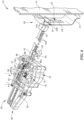
Figure 6 is a perspective view of the dishwasher rack in an upper deployed position and illustrating an embodiment of the release mechanism positioning the rack and locking mechanism in an unlocked configuration releasably securing the position of the dishwasher rack and positioning the reset mechanism in the extended position; -
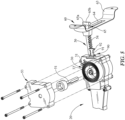
Figure 7 is a perspective exploded view of the embodiment of the retracting, locking, and reset mechanisms; -
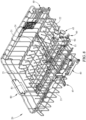
Figure 8 is a perspective view of the embodiment of the dishwasher rack ofFig. 1 . - Numerous variations and modifications will be apparent to one of ordinary skill in the art, as will become apparent from the description below. Therefore, the invention is not limited to the specific implementations discussed herein.
- The embodiments discussed hereinafter will focus on the implementation of the hereinafter-described apparatus and techniques within a front-load residential dish washing machine such as
dish washing appliance 10, such as the type that may be used in single-family or multi-family dwellings, or in other similar applications. However, it will be appreciated that the herein-described apparatus and techniques may also be used in connection with other types of dish washing machines in some embodiments. For example, the herein-described apparatus and techniques may be used in commercial applications in some embodiments. - Embodiments for a dish washing machine are shown herein for ease of understanding. For example, a front-load dish washing machine that includes a front-mounted
door 12 in a cabinet orhousing 11 that provides access to a horizontally-orienteddishwasher rack 20 housed within the cabinet orhousing 11 may be used. More specifically, thedishwasher rack 20 may be housed in adishwasher tub 14. Implementation of the herein-described apparatus and techniques within a variety of appliances would be well within the abilities of one of ordinary skill in the art having the benefit of the instant disclosure, so the invention is not limited to the front-load dish washing implementation discussed further herein. For example, the apparatus and techniques may be used with a dishwasher drawer of a dish washing appliance. - Turning now to the drawings, wherein like numbers denote like parts throughout the several views,
Fig. 1 illustrates an exampledish washing appliance 10 in which the various technologies and techniques described herein may be implemented.Dish washing appliance 10 is a front-load dish washing machine, and as such may include a front-mounteddoor 12 defining anopening 13 that provides access to a horizontally-orienteddishwasher tub 14. Thedoor 12 may be coupled with a cabinet orhousing 11 that may house thedishwasher tub 14 in some embodiments.Door 12 is generally hinged along a front or front edge of thehousing 11 adjacent theopening 13 and is pivotable between the opened position illustrated inFigs. 1 and2 and a closed position (not shown). Whendoor 12 is in the open position, dishes, utensils, pans, and other washable items may be inserted into and removed from the one or more dishwasher racks 20 through the opening 13 in the front of cabinet orhousing 11. Control overdish washing appliance 10 by a user is generally managed through acontrol panel 18 disposed on a door 12 (not shown) and implementing auser interface 19, and it will be appreciated that in different dish washing machine designs,control panel 18 may include various types of input and/or output devices, including various knobs, buttons, lights, switches, textual and/or graphical displays, touch screens, etc. through which a user may configure one or more settings and start and stop the dishwasher rack cycle or movement as described herein. For example, the control panel, or portions thereof, may be included with the dishwasher rack, on the interior or exterior of the door, and/or adjacent the rack within the opening of the dish washing machine. For example in some embodiments, portions of the controls may be accessible when the door is in the open position. In other embodiments, the one or more racks may close/open, lock, and/or unlock from a position by proximity of one or more users and/or by a one or more gestures/forces or bodily movement relative to the rack and/or portions of the dish washing machine. - As shown in the figures, the one or more dishwasher racks 20, or portions thereof, may be positionable relative to the
dish washing appliance 10 between a stowed or un-deployed position (Figs. 1 and3 ) and a deployed or different position (Figs. 2 ,4 ,5 , and6 ). At least one of the stowed positions of thedishwasher rack 20 may be used when one or more of the washing cycles is in operation. In use, the deployed position may be one or more horizontal positions different from one or more of the stowed positions. For example in one embodiment, one deployed position or partially opened position may be a position other than when the rack is in its fully extended position out of thedishwasher tub 14. One or more deployed positions may be a horizontal position to dry, load, and/or unload dishes, utensils, or the like. The one or more dishwasher racks 20 may travel in a substantially horizontal plane. The horizontal plane may be into and/or out of thedishwasher tub 14 or cavity. Although the substantially linear movement of the dishwasher rack cycle may occur along the horizontal plane in a variety of heights as shown, the linear travel may be in a variety of angles in one or both the directions into or out of a position. - As illustrated in the figures, the
dishwasher rack 20 may be retractable to return towards the stowed position with reduced or no assistance by the user. The user has the ability to manually increase the spring/restore force of one or more torsion springs 30 (e.g.Fig. 5 ) when positioning thedishwasher rack 20 towards one or more deployed positions or away from thedishwasher tub 14. The torsion spring force or restore force of thetorsion spring 30 drives/urges thedishwasher rack 20, or portions thereof, towards the stowed position. In the stowed position, thetorsion spring 30 may be at rest or an untensioned state, or a less tensioned state than when in one or more deployed positions. When the user progressively forces the dishwasher rack 20 in a direction away from thedishwasher tub 14, thetorsion spring 30 increases in tension to one or more tensioned states, such that energy is stored within thetorsion spring 30. The energy stored while pulling out thedishwasher rack 20 may automatically return/retract thedishwasher rack 20 back towards the stowed position and/ordishwasher tub 14 when released by the user. As shown in the embodiment, thedishwasher rack 20 may be releasably secured/locked temporarily in one or more deployed positions until released (e.g. release mechanism, controls, switch, button, handle, force, etc.) towards thedishwasher tub 14 or one or more positions (e.g. the stowed position and/or deployed position more proximal to the dishwasher tub). Although the dishwasher rack spring or tension device may be atorsion spring 30, the spring may be a variety of constructions, shapes, sizes, quantities, and positions with the dishwasher rack. In some embodiments, the torsion spring may be a clock spring and/or coil spring. In a preferred embodiment, the torsion spring may be a spiral or clock spring as shown. - The
dishwasher rack 20 may be the upper and/or lower dishwasher rack in some embodiments. In a preferred embodiment as shown, thedishwasher rack 20 is the upper dishwasher rack. The upper dishwasher rack may be pulled outward by the user, and upon release thedishwasher rack 20 may automatically retract back into the cavity, under the stored power of thetorsion spring 30. In some embodiments, one or more portions of a dishwasher rack may be auto-retracted towards a stowed position within adishwasher rack 20 and/ortub 14. The dishwasher rack is adjustable to a plurality of heights and still allows retraction from the deployed position to the stowed position. Thedishwasher rack 20 may include a variety of rack height adjustment brackets ormechanisms 40 allowing the rack to adjust between at least two heights (e.g. upper height, lower height, etc.) within the dishwasher tub. In various embodiments, thebrackets 40 are positioned adjacent theside walls 21 of the basket orrack 20 adjacent the typical extensions, slides, wheels, rollers, or glides 42 adjacent thedishwasher tub 14 to allow the translation with respect thereto and still allow the auto-retract apparatus and techniques to be used. As shown inFig. 1 , theupper rack 20 is positioned in the lower or first position relative to thetub 14 and correspondingly theheight adjustment device 60 is in a lower position (e.g. the slidingengagement 62 or slidingmember 65 is in the lower position). Conversely as shown inFig. 2 , theupper rack 20 is positioned in the upper or second position relative to thetub 14 and correspondingly theheight adjustment device 60 is in an upper position (e.g. the slidingengagement 62 or slidingmember 65 is in the upper position). Thedishwasher rack 20 and/or retractingmechanism 50 may retract in at least two or more vertical positions or heights. Further, thedishwasher rack 20 may also include one or more adjustable spray arms orassemblies 45 in some embodiments repositioned with the rack's height adjustment. Thespray arms 45 may be in fluid communication with one ormore docking stations 17 when the rack is in the stowed position in one or more of the adjustable heights of therack 20. - As illustrated in the figures, the
torsion spring 30 stores energy/power to automatically retract thedishwasher rack 20 back towards the stowed position inside thedishwasher tub 14. In the embodiment shown, theretracting mechanism 50 includes at least apinion gear 52 rotationally and translationally engaging arack gear 54 tensioned by thetorsion spring 30 to translate therack 20. Thepinion gear 52 of thedishwasher rack 20 may include at least one axle or gearedelongated shaft 51 with one or more geared or toothed engagements 52s. Thepinon gear 52 operably engages therack gear 54, such as an elongated rail withteeth 54a. Although therack gear 54 is shown centrally located/extending from the rack orrear wall 22 or spaced inwardly and away from theside walls 21 of the rack and/ordishwasher tub 14, it should be understood that therack gear 54 and/or retractingmechanism 50 may be positioned adjacent to or on the interior of thedishwasher tub 14. The geared engagement between theshaft 51 andrail 54 reduces slipping and allows continuous rotation and translation of theshaft 51/rack 20 relative to therail 54. Thetorsion spring 30 may be secured to both the rotationally translating pinion gear 52 (e.g. geared shaft 51) and to a remaining portion of the translatingdishwasher rack 20 orhousing 53. For example, thetorsion spring 30 may be fixed at one end to theshaft 51 and the other end to the basket orrack 20 and/or gearbox/housing 53. As theshaft 51 and pinion gear/gearedwheel 52 rotate together translationally along theelongated rail 54 of gearedteeth 54a (e.g. when dishwasher rack is positioned towards the deployed position), thetorsion spring 30 winds up thereby increasing the tension force or stored energy. It should be understood, the counter rotation of the shaft oraxle 51 and/orpinion gear 52 may correspondingly reduce the tension force in some embodiments. - In some implementations, the
rack gear 54 and thepinion gear 52 may be orientated and/or positioned in a variety of ways and methods to thedishwasher rack 20. As shown inFigs. 3 and4 , theshaft 51 andpinion gear 52 rotate about a vertical axis A and engage theteeth 54a of therack gear 54 orientated laterally towards theside walls tub torsion spring 30 may also be tensioned about the vertically orientatedshaft 51. Therack gear 54 andpinion 52 may be positioned inwardly or centrally to the side walls of the dishwasher rack and/or tub. Therack gear 54 andpinion gear 52 may be positioned above the spray arm assembly 45 (e.g. rotating spray arms) as in the embodiment shown. The geared rail orrack gear 54 may project from therear wall 15 of thetub 14. Therack gear 54 may be extended in a direction from therear wall 22 of therack 20 to thefront wall 23 of therack 20 and be positioned adjacent thebottom wall 24 of therack 20 above the extent of thespray arm assembly 45. As such, dishware or items may be positioned within the rack above one or more portions of the retracting mechanism (e.g. housing, rack gear, pinion gear, etc.). - The embodiment of the
dishwasher rack 20 shown in Figures includes theshaft 51 and at least one gearedwheel 52. The geared engagement (e.g. betweenrail 54 and geared wheel 52) that winds-up thetorsion spring 30 may be in the central portion of thedishwasher rack 20 between opposing one ormore slides 42 connecting thedishwasher rack 20 to thedishwasher tub 14. - The
rack gear 54 and thepinion gear 52 of theretracting mechanism 50 may be positioned with therack 20 at a variety of heights relative to the dishwasher tub and still retract and/or extend between the deployed and stowed positions. A portion of theretracting mechanism 50 may maintain translationally fixed (e.g. in the direction of rack deployment or retraction, horizontal direction) or engaged to a stationary or remaining portion of the dishwasher tub or appliance. - A
height adjustment device 60 allows theretracting mechanism 50 and/or rack gear 54 (e.g. rails with gear teeth) to be in a translationally fixed positon within thetub 14 when the retracting rack cycles between stowed and deployed positions. This allows therack gear 54 to travel vertically with therack 20 between a plurality of heights within the dishwasher via bracket 40 (e.g. different heights inFigs. 2 and3 ). Theheight adjustment device 60 may engage a portion of theretracting mechanism 50 to therear wall 15 of thedishwasher tub 14 or another fixed appliance structure. Theheight adjustment device 60 maintains theretracting mechanism 50 of thedishwasher rack 20 engaged to thedishwasher tub 14 between different vertical positions. In one implementation, therack gear 54 is fixed to the dishwasher tub 14 (e.g. rear wall 15) independent of the height of therack 20 within thedishwasher tub 14. Theheight adjustment device 60 may include a slidingengagement 62 between the retractingmechanism 50 and thedishwasher tub 14 and/orappliance 10 to allow the retracting mechanism to slide vertically in a vertical direction between vertical positons and still remain fixed in one or more directions perpendicular to the vertical direction. The slidingengagement 62 may include a pin and slot engagement. As shown in the embodiment, the pin and slot engagement, if used, may include abracket 63 secured to therear wall 15 of thedishwasher tub 14 having a slot 64 (e.g. vertical). It should be understood that therear wall 15 may include a slot without having a separate bracket in some embodiments. A vertical slidingmember 65 may slide in a vertical direction and still be attached to therear wall 15. As shown in the embodiment in the figures, the slidingmember 65 may extend from therack gear 54 and comprise apin 65a slideably engaging theslot 64 between the two or more heights of therack 20 and/or retractingmechanism 50. Thepin 65a may have a bar orretention structure 65b restricting removal (e.g. horizontal, transverse to slot movement) from theslot 64. The translational movement of thepin 65a away from thebracket 63 and/orrear wall 15 of thetub 14 may be limited to fix the translational movement of therack gear 54. Although theheight adjustment device 60 may be centrally located in therack 20 and/or tub 14 (e.g. spaced away from each one of the opposingside walls 16 of the tub), it should be understood that theretracting mechanism 50 and/orheight adjustment device 60 may be spaced or positioned in a variety of positions relative to the rack 20 (e.g.side wall 21, 16). - It should be understood that the
height adjustment device 60 for theretracting mechanism 50 and/orrack 20 may be a variety of constructions, quantities, positions, shapes, and sizes and still be within the scope of the invention. For example, thepin 65a may be projecting from therear wall 15 of thedishwasher tub 14 and theslot structure 64 may be coupled to the retracting mechanism and/or rack. Moreover, in some implementations, the retracting mechanism 50 (e.g. rack gear) may be coupled to therear wall 15 of thedishwasher tub 14 by a flexible member or cable. In some implementations, a wheel and rail engagement may couple the retracting mechanism to the tub (e.g. rear wall). Moreover, in various embodiments, a magnet configuration or a pulley system may be used for coupling and rack height adjustment for maintaining operation of the retracting feature. - In some embodiments as shown, the
dishwasher rack 20 may include alocking mechanism 70 securing the position of thedishwasher rack 20. Thelocking mechanism 70 may secure thedishwasher rack 20 in at least one deployed position. In various embodiments, thelocking mechanism 70 may secure the dishwasher rack in the one or more stowed positions. One embodiment of thelocking mechanism 70 as shown inFigs. 3 and4 is apawl 72 and ratchet 74 engagement. Theratchet 74 is fixed to theshaft 51 and rotates about the vertical or rotating axis A. Thepawl 72 pivots about an axis (e.g. vertical axis) relative to the ratchet. In some implementations, theratchet 74 andpawl 72 may be positioned along theshaft 51 between thepinion gear 52 and the torsions spring 30 (e.g. within the housing 53). The pawl and ratchetengagement dishwasher rack 20 is pulled outward, thetorsion spring 30 tightens to store energy, and theratchet 74 andshaft 51 slips/rotates past thepawl 72. Moreover, when the user stops pulling and releases thedishwasher rack 20, thetorsion spring 30 starts to urge/move thedishwasher rack 20 back towards thedishwasher tub 14, thepawl 72 will engage to the ratchet/shaft dishwasher rack 20 in the translational position. This locking mechanism or feature 70 may work at the fully extended position as well as any position between the stowed and deployed position, as well as the stowed position in some embodiments. - In some implementations, the
retracting mechanism 50 and/orlocking mechanism 70 may include arelease mechanism 80. Therelease mechanism 80 allows theshaft 51 and/orpinion gear 52 to rotate freely when actuated. Actuation may occur in a variety of ways either with direct contact and/or motion by the user. In the embodiment shown, the user operates a user release control 81 (e.g. a handle, button, or switch). Therelease control 81 is shown in one embodiment as adjacent afront wall 23 of thedishwasher rack 20. Therelease control 81 is linked to or in operable communication (e.g. unlock, lock) with thelocking mechanism 70 of theretracting mechanism 50. Therelease control 81 may reset the locking/retracting mechanism - In the embodiment shown, the
release mechanism 80 positions thelocking mechanism 70 from a locked configuration (Fig. 4 ) to an unlocked configuration (Fig. 6 ). When in the locked configuration, thepinion gear 52 may rotate in the forward direction to allow therack 20 to translate towards the deployed positon but not in a backward direction towards the stowed position. In the embodiment shown when thelocking mechanism 70 is in the locked configuration, thepawl 72 is operably engaging theratchet 74 allowing free motion in one rotational direction and provides a hard stop when turned the other rotational direction. When the locking mechanism is in the unlocked configuration, thepinion gear 52 rotates in both the forward and backward directions allowing therack 20 to translate between the stowed and deployed positions. As shown inFig. 6 , thepawl 72 is rotated out of engagement with theratchet 74 when in the unlocked configuration. When therack 20 is in the deployed position and therelease mechanism 80 unlocks thelocking mechanism 70, the torsion spring urges the dishwasher rack towards the stowed positon. - The
locking mechanism 70 orpawl 72 may be rotated or moved out of engagement with the ratchet or to the unlocked configuration in a variety of ways to allow retracting of the dishwasher rack. As shown in the Figures, one embodiment of therelease mechanism 80 is acable mechanism 82, although a variety of linkage or mechanisms may be used. Releasing or lifting up on the handle or controls 81 disengages or unlocks the pawl/shaft/ratchet 72/51/74, via thecable 82 through thehousing 53, if used, allowing thetorsion spring 30 to auto-retract thedishwasher rack 20 back towards thedishwasher tub 14. In the embodiment shown, thehandle 81 via acable 82 may pivot and/or translatelinkage 83 to reposition thepawl 72 to the unlocked configuration. Thecable 82 may rotate a member orlinkage 83 to drive a gearedrail 84 withteeth 84a rotationally engaged to gearteeth 72a of thepawl 72 or pawl shaft, wherein translation of therail 84 rotates thepawl 72. Thegear teeth 72a of the pawl/shaft 72 thereby rotate the pawl between the locked configuration (Fig. 3 ) and the unlocked configuration (Fig. 6 ). The gearedrail 84 andpawl 72 may reset in a variety of ways. In one embodiment, the geared rail and pawl may be spring loaded (e.g. spring 85) to reset/or return the rail/pawl to the locked configuration or rest position returning the pawl to the engaged or locked configuration. - The release mechanism may include a
catch 86 in various embodiments. Thecatch 86 may be positioned or pivoted about an axis into and out of engagement with the locking and/or release mechanism. The catch may be spring loaded to reset or return to a variety of positons. As shown inFig. 6 , acatch 86 may be used to retain the locking mechanism (e.g. pawl 72) or release mechanism in the unlocked configuration to allow rack retraction for a distance. Thecatch 86 may be used to retain the gearedrail 84 and/orpawl 72 of the release in the unlocked or extended configuration to maintain the pawl in the unlocked configuration. Thecatch 86 may be spring loaded (e.g. spring 87) in some embodiments. The linear positon of the gearedrail 84 may position or correspond to thecatch 86 between the unlocked configuration and locked configuration. Interference by the gearedrail 84 may maintain the catch in the locked configuration for the pawl as shown inFig. 3 . A receptacle/opening or retainingfeature 88 may be positioned within the gearedrail 84 and when translated towards the catch (e.g. distal free end orhook 86a), the catch inserts into the retainingfeature 88 and holds the geared rail/pawl 84/72 in the rotated and unlocked configuration when the rack is released from the deployed position. - In various embodiments, a
reset mechanism 90 positions thelocking mechanism 70 and/orrelease mechanism 80 from the unlocked position or configuration to the locked position or configuration. In the embodiment shown, thereset mechanism 90 operates when thedishwasher rack 20 returns to the stowed position from the deployed position. In some implementations, thereset mechanism 90 returns thepawl 72 to the locked configuration (Fig. 3 ) allowing thedishwasher rack 20 to be deployed and subsequently locked in position relative to the dishwasher tub and/or portions of the retracting mechanism. In the embodiment shown, thereset mechanism 90 resets the catch/pawl 86/72 when returned to the stowed position. It should be understood that the reset mechanism may be actuated in one or more positons of the dishwasher rack and while the rack is moving. Thereset mechanism 90 disengages thecatch 86 from the gearedrail 84 allowing thepawl 72 to rotate and return to the locked configuration. Thereset mechanism 90 may include areset pin 91. Thereset pin 91 may be triggered by contact when moving towards the stowed positon. Thereset pin 91 may extend through the sidewall (e.g. rear side) of thehousing 53. Thereset pin 91 is positioned linearly via thecatch 86 and may be spring loaded (e.g. spring 87) in a direction in some embodiments. As shown inFigs. 3 and4 , thereset pin 91 is in a retracted positioned within thehousing 53 when thecatch 86,rail 84, and/orpawl 72 is in the locked configuration. Correspondingly, as shown inFig. 6 , thereset pin 91 is positioned in an extended positon away from thehousing 53 when thecatch 86 holds thepawl 72 and/orrail 84 in the unlocked position. Thespring 87 may urge thereset pin 91 to the extended position. With the reset pin in the extended position and thetorsion spring 30 returning with the rack to the stowed position as inFig. 6 , the free end 92 (e.g. a T-bar shaped end) of thereset pin 91 abuts or makes contact with structure pushing/translating thereset pin 91 to release thecatch 86. Thereset pin 91 rotates thecatch 86 orhook 86a from the retainingfeature 88 of therail 84 when the reset pin translates from the extended positon to the retracted position. In the embodiment shown, the reset pin may have a retaining feature or receptacle engaging a pivot arm of the catch to rotate thecatch hook 86a from therail 84. Correspondingly, the pivot arm of the catch or catch 86 translates the reset pin from the retracted position to the extended position when thecatch 86 rotates from the locked configuration to the unlocked configuration. In the embodiment shown inFig. 3 , the triggering structure that thereset pin 91 contacts to push the reset pin in one or more directions may be therear wall 15 of thetub 14 and/or height adjustment mechanism 60 (e.g. bracket 63) when thedishwasher rack 20 is in at least one of the one or more heights (e.g. upper, lower heights) of thedishwasher rack 20. It should be understood that the reset pin may make contact with or be pushed between the extended and retracted positions by a remaining portion of the appliance and/or rack that is fixed in positon relative to the dishwasher rack. - Although a handle or
manual release control 81 may be used in some embodiments to disengage thelocking mechanism 70, the user may push or pull thedishwasher rack 20 with sufficient force and distance in at least one direction (e.g. towards or away from the dishwasher tub and/or upwards/downwards) and release the rack to engage the auto-retract feature and allow thetorsion spring 30 to use the stored energy to position the dishwasher rack towards and/or to the stowed/home position. If a handle is used in some embodiments, such as without areset mechanism 90, the handle may stay released from thelocking mechanism 70 for sufficient time to allow thedishwasher rack 20 to return to the stowed position before reengagement. For example, a handle may be reset back (e.g. by a cam, spring, and/or damper) to the home position when reaching or approaching the stowed position. - In addition, in various embodiments, the
dishwasher rack 20 may include a housing orgearbox 53 to include one or more portions of theretracting mechanism 50,reset mechanism 90,release mechanism 80, etc. The housing orgearbox 53 is positioned adjacent therear wall 22 of thedishwasher rack 20. In various embodiments, the housing may extend along the rack from therear wall 22 to thefront wall 23 of the rack or adjacent the release controls in some embodiments. Thereset pin 91,release control 81, and/or therack gear 54 may extend/retract/project from the housing, if used. Thehousing 53 may include thetorsion spring 30, theratchet 74, the gearedwheel 52, theshaft 51, thepawl 72, thecatch 86, etc. or portions thereof as shown in the Figures. Thetorsion spring 30 may be positioned within thehousing 53 in some embodiments as shown inFigs. 5 and7 . Afixed end 31 of thetorsion spring 30, opposite a fixed end 32 attached to theshaft 51, may be secured to thehousing 53, if used, in some embodiments. In some embodiments, thetorsion spring 30 may be attached to theshaft 51 and a variety of other structures of the translatingdishwasher rack 20. Although, onetorsion spring 30 and/or onehousing 53 is shown as being used in one embodiment, a plurality ofsprings 30 and/orhousings 53 may be used on oneshaft 51 or a plurality of geared shafts. Although thetorsion spring 30 may be shown in thehousing 53 in the embodiments, thetorsion spring 30 may be combined with the one or more geared engagements orwheels 52 and/or the gearedrail 54. As shown more clearly inFig. 7 , thehousing 53 may have one or more compartments for the internal structure. As shown in the embodiment, one sequence within the housing from bottom to top may be thepinion gear 52 andrack gear 54, theratchet 74,pawl 72, catch 86 and resetpin 91, and thetorsion spring 30. Theshaft 51 may extend through the housing/compartment between the pinion gear, ratchet, and the torsion spring. Moreover, thehousing 53 may be sealed (e.g. hermetically sealed, gaskets, etc.) to reduce water and/or detergent from entering. In some embodiments, thehousing 53 may also include one or more drains or weep holes to allow moisture to escape. - In some embodiments, the
dishwasher rack 20 may include one or more dampers or dampening devices (not shown). One or more dampers may slow the translation of thedishwasher rack 20 from one position to another (e.g. into and/or out of the dishwasher tub, or from the deployed position to another position or stowed position). The damper may limit the retracting speed to one or more values. The damper may be a rotational damper (e.g. friction or liquid) attached to theshaft 51 and/or rack wire basket. The rotational damper may slow down the rotation of theshaft 51 and/orgear wheels 52 and correspondingly the translation of thedishwasher rack 20 in at least the direction towards thedishwasher tub 14 and/or stowed position. It should be understood that the dampers may be a variety of constructions, quantities, positions, and sizes and still be within the scope of the invention. For example, the damper may be a linear damper (e.g. a mechanical spring or pneumatic cylinder). Moreover, the damper may be located within thehousing 53 in some embodiments. The damper and thetorsion spring 30 may be attached to theshaft 51 and positioned within the housing. Moreover, a one-way damper may be used to lock the dishwasher rack in tension in one or more positions. The one-way damper may maintain the position of the rack, until an additional force is applied to push/pull the rack into/out of the tub to unbalance the tension from the torsion spring and the friction damper. - While several embodiments have been described and illustrated herein, those of ordinary skill in the art will readily envision a variety of other means and/or structures for performing the function and/or obtaining the results and/or one or more of the advantages described herein. More generally, those skilled in the art will readily appreciate that all parameters, dimensions, materials, and configurations described herein are meant to be exemplary and that the actual parameters, dimensions, materials, and/or configurations will depend upon the specific application or applications for which the teachings is/are used. Those skilled in the art will recognize, or be able to ascertain using no more than routine experimentation, many equivalents to the specific embodiments described herein. It is, therefore, to be understood that the foregoing embodiments are presented by way of example only and that, within the scope of the appended claims, embodiments may be practiced otherwise than as specifically described.
- All definitions, as defined and used herein, should be understood to control over dictionary definitions, definitions in documents incorporated by reference, and/or ordinary meanings of the defined terms.
- The indefinite articles "a" and "an," as used herein in the specification and in the claims, unless clearly indicated to the contrary, should be understood to mean "at least one."
- The phrase "and/or," as used herein in the specification and in the claims, should be understood to mean "either or both" of the elements so conjoined, i.e., elements that are conjunctively present in some cases and disjunctively present in other cases. Multiple elements listed with "and/or" should be construed in the same fashion, i.e., "one or more" of the elements so conjoined. Other elements may optionally be present other than the elements specifically identified by the "and/or" clause, whether related or unrelated to those elements specifically identified. Thus, as a non-limiting example, a reference to "A and/or B", when used in conjunction with open-ended language such as "comprising" can refer, in one embodiment, to A only (optionally including elements other than B); in another embodiment, to B only (optionally including elements other than A); in yet another embodiment, to both A and B (optionally including other elements); etc.
- As used herein in the specification and in the claims, "or" should be understood to have the same meaning as "and/or" as defined above. For example, when separating items in a list, "or" or "and/or" shall be interpreted as being inclusive, i.e., the inclusion of at least one, but also including more than one, of a number or list of elements, and, optionally, additional unlisted items. Only terms clearly indicated to the contrary, such as "only one of" or "exactly one of," or, when used in the claims, "consisting of," will refer to the inclusion of exactly one element of a number or list of elements. In general, the term "or" as used herein shall only be interpreted as indicating exclusive alternatives (i.e. "one or the other but not both") when preceded by terms of exclusivity, such as "either," "one of," "only one of," or "exactly one of." "Consisting essentially of," when used in the claims, shall have its ordinary meaning as used in the field of patent law.
- As used herein in the specification and in the claims, the phrase "at least one," in reference to a list of one or more elements, should be understood to mean at least one element selected from any one or more of the elements in the list of elements, but not necessarily including at least one of each and every element specifically listed within the list of elements and not excluding any combinations of elements in the list of elements. This definition also allows that elements may optionally be present other than the elements specifically identified within the list of elements to which the phrase "at least one" refers, whether related or unrelated to those elements specifically identified. Thus, as a non-limiting example, "at least one of A and B" (or, equivalently, "at least one of A or B," or, equivalently "at least one of A and/or B") can refer, in one embodiment, to at least one, optionally including more than one, A, with no B present (and optionally including elements other than B); in another embodiment, to at least one, optionally including more than one, B, with no A present (and optionally including elements other than A); in yet another embodiment, to at least one, optionally including more than one, A, and at least one, optionally including more than one, B (and optionally including other elements); etc.
- It should also be understood that, unless clearly indicated to the contrary, in any methods claimed herein that include more than one step or act, the order of the steps or acts of the method is not necessarily limited to the order in which the steps or acts of the method are recited.
- It is to be understood that the embodiments are not limited in its application to the details of construction and the arrangement of components set forth in the description or illustrated in the drawings. The invention is capable of other embodiments and of being practiced or of being carried out in various ways. Unless limited otherwise, the terms "connected," "coupled," "in communication with," and "mounted," and variations thereof herein are used broadly and encompass direct and indirect connections, couplings, and mountings. In addition, the terms "connected" and "coupled" and variations thereof are not restricted to physical or mechanical connections or couplings.
- The foregoing description of several embodiments of the invention has been presented for purposes of illustration. It is not intended to be exhaustive or to limit the invention to the precise steps and/or forms disclosed, and obviously many modifications and variations are possible in light of the above teaching.
Claims (9)
- A dish washing appliance (10) comprising:a dishwasher tub (14) having an opening defined by opposing side walls (16) and a rear wall (15) opposite the opening; anda dishwasher rack (20) having a rack height adjustment bracket (40), wherein the rack height adjustment bracket adjusts the dishwasher rack between at least two heights within the dishwasher tub; characterised in that:the dishwasher rack includes a retracting mechanism (50) and a height adjustment device (60) maintaining the retracting mechanism of the dishwasher rack engaged to the dishwasher tub in each one of the at least two heights within the dishwasher tub, and wherein the dishwasher rack includes one or more torsion springs (30), the spring force of the one or more torsion springs urging the dishwasher rack (20) towards a stowed position of the dishwasher rack (20),and the retracting mechanism is configured to automatically return the dishwasher rack from a deployed position to the stowed position via the one or more torsion springs (30); andthe height adjustment device includes a sliding engagement (62) between the retracting mechanism and the dishwasher tub.
- The dish washing appliance of claim 1 wherein the height adjustment device (60) engages the retracting mechanism (50) to the rear wall of the dishwasher tub.
- The dish washing appliance of either claim 1 or 2 wherein the height adjustment device and the retracting mechanism are spaced away from each one of the opposing side walls of the dishwasher tub.
- The dish washing appliance of claim 1 wherein the sliding engagement includes a pin and slot engagement.
- The dish washing appliance of claim 4 wherein the pin and slot engagement includes a bracket (63) having a slot (64) and is fixed to the dishwasher tub, and wherein the dishwasher rack has a sliding member (65) that includes a pin (65a) sliding within the slot of the bracket between the at least two heights while limiting the translation of the pin away from the rear wall.
- The dish washing appliance of claim 1 wherein the dishwasher rack includes an adjustable spray arm (45) in fluid communication with a docking station when in the stowed position when in one or more of the at least two heights.
- A method of allowing height adjustment of a retracting dishwasher rack (20) within a dish washing appliance (10) comprising the steps of:providing a dishwasher rack having one or more torsion springs (30);positioning the dishwasher rack from a stowed position to one or more deployed positions;positioning the dishwasher rack between a first height and a lower second height;engaging a portion of a retracting mechanism (50) to a rear wall (15) of a dishwasher tub (14) at the first height and the lower second height;increasing a tension force of the one or more torsion springs when positioning the dishwasher rack from the stowed position towards the one or more deployed positions at each one of the first height and the lower second height; andretracting the dishwasher rack from the one or more deployed positions towards the stowed position in each one of the first height and the lower second height;the method further comprising the step of:
maintaining and slidably engaging the portion of the retracting mechanism to the rear wall of the dishwasher tub between the first height and the lower second height via a height adjustment device (60). - The method of claim 7, further comprising the step of docking an adjustable spray arm (45) of the dishwasher rack with a docking station (17) at the first height and the lower second height, and/or
further comprising the step of translating the portion of the retracting mechanism relative to the rear wall of the dishwasher tub between the first height and the lower second height. - The method of claim 7 wherein the dishwasher rack includes a geared wheel (52) rotationally engaging one or more rails (54) with corresponding geared teeth (54a).
Applications Claiming Priority (2)
| Application Number | Priority Date | Filing Date | Title |
|---|---|---|---|
| US16/214,778 US10582828B1 (en) | 2018-12-10 | 2018-12-10 | Retracting dishwasher rack system |
| PCT/CN2019/097434 WO2020119130A1 (en) | 2018-12-10 | 2019-07-24 | Retracting dishwasher rack system |
Publications (3)
| Publication Number | Publication Date |
|---|---|
| EP3863494A1 EP3863494A1 (en) | 2021-08-18 |
| EP3863494A4 EP3863494A4 (en) | 2022-04-06 |
| EP3863494B1 true EP3863494B1 (en) | 2025-03-05 |
Family
ID=69723533
Family Applications (1)
| Application Number | Title | Priority Date | Filing Date |
|---|---|---|---|
| EP19896098.1A Active EP3863494B1 (en) | 2018-12-10 | 2019-07-24 | Dish washing appliance with retracting dishwasher rack system, and method of allowing height adjustment |
Country Status (4)
| Country | Link |
|---|---|
| US (1) | US10582828B1 (en) |
| EP (1) | EP3863494B1 (en) |
| CN (1) | CN113365540B (en) |
| WO (1) | WO2020119130A1 (en) |
Families Citing this family (1)
| Publication number | Priority date | Publication date | Assignee | Title |
|---|---|---|---|---|
| US12185894B2 (en) * | 2022-04-14 | 2025-01-07 | Haier Us Appliance Solutions, Inc. | Magnetic height adjustment assembly for dishwasher racks |
Family Cites Families (84)
| Publication number | Priority date | Publication date | Assignee | Title |
|---|---|---|---|---|
| US3402576A (en) | 1966-02-28 | 1968-09-24 | Michael R. Krupsky | Combination clothes washer, dryer, dishwasher, drycleaner, and garment appearance-finishing machine |
| US3466105A (en) | 1967-12-21 | 1969-09-09 | Gen Electric | Door-operated rack extending and retracting means for a front-opening appliance cabinet |
| US3560069A (en) | 1969-07-01 | 1971-02-02 | Gen Electric | Adjustable rack assembly in an automatic dishwasher |
| FR2054728A5 (en) | 1969-07-24 | 1971-05-07 | Carpano & Pons | |
| US3736037A (en) | 1971-06-01 | 1973-05-29 | Gen Electric | Rack level adjustment apparatus in an appliance cabinet |
| US3726581A (en) | 1971-06-01 | 1973-04-10 | Gen Electric | Rack level adjustment apparatus in an appliance cabinet |
| US3892453A (en) | 1974-10-07 | 1975-07-01 | Fedders Corp | Dishrack adjustment |
| US5657878A (en) | 1995-07-12 | 1997-08-19 | Illinois Tool Works Inc. | Adjustable height mechanism for a dishwasher rack |
| IT1289498B1 (en) | 1996-12-20 | 1998-10-15 | Smeg Spa | HEIGHT POSITION VARIATION DEVICE FOR ADJUSTABLE DISHWASHER BASKET AT DIFFERENT HEIGHTS |
| US5860716A (en) | 1997-03-28 | 1999-01-19 | White Consolidated Industries, Inc. | Dishwasher rack adjustment mechanism |
| US6048006A (en) | 1997-09-12 | 2000-04-11 | Southco, Inc. | Ratcheting pawl latch |
| JP3572224B2 (en) | 1999-08-20 | 2004-09-29 | 株式会社東芝 | Dishwasher |
| NZ500167A (en) | 1999-10-08 | 2002-07-26 | Fisher & Paykel Appliances Ltd | Dishwasher adapted to be mounted in a cavity |
| US6247771B1 (en) | 2000-08-18 | 2001-06-19 | Evelyn J. Miller | Lower rack lifting device for a dishwasher |
| KR20030011496A (en) | 2001-08-03 | 2003-02-11 | 주식회사 대양에스티 | Apparatus for transporting rack in rack type of dishwasher |
| DE10246438A1 (en) | 2002-10-04 | 2004-04-15 | Grass Gmbh | drawer system |
| US20040244825A1 (en) * | 2003-06-06 | 2004-12-09 | Ashton Robert H. | Dishwasher with drawer lifting mechanism |
| US7296830B2 (en) | 2003-07-10 | 2007-11-20 | Southco, Inc. | Rotary pawl latch |
| DE20311795U1 (en) | 2003-07-31 | 2004-11-18 | Alfit Ag | Drawer pull-out guide with automatic retraction with integrated damping |
| DE10347765A1 (en) | 2003-10-14 | 2005-05-12 | Bsh Bosch Siemens Hausgeraete | Crockery basket with height-adjustable shelves |
| SE0401122D0 (en) * | 2004-04-29 | 2004-04-29 | Electrolux Home Prod Corp | Basket lifting arrangement for a dishwasher |
| US7410228B2 (en) | 2004-12-08 | 2008-08-12 | Whirlpool Corporation | Height adjuster mechanism for a dishwasher dish rack |
| DE102005010616A1 (en) * | 2005-03-08 | 2006-09-14 | BSH Bosch und Siemens Hausgeräte GmbH | Dishwasher with a storage container |
| US20060237042A1 (en) | 2005-04-25 | 2006-10-26 | Viking Range Corporation | Rack adjustment mechanism for an article cleaning apparatus |
| US20070039904A1 (en) | 2005-08-18 | 2007-02-22 | Electrolux Home Products, Inc. | Brackets for supporting article holders |
| US7628461B2 (en) * | 2006-07-20 | 2009-12-08 | Maytag Corporation | Bottom mount refrigerator having an elevating freezer basket |
| US7731804B2 (en) | 2006-08-09 | 2010-06-08 | Maytag Corporation | Lid operating mechanism for a drawer-type dishwasher |
| JP5571383B2 (en) | 2006-08-16 | 2014-08-13 | サウスコ,インコーポレイティド | Rotating claw latch |
| KR20080030139A (en) | 2006-09-29 | 2008-04-04 | 엘지전자 주식회사 | washer |
| US7731805B2 (en) * | 2006-11-30 | 2010-06-08 | General Electric Company | Dishwasher rack lift system |
| KR101290374B1 (en) | 2006-12-14 | 2013-07-26 | 엘지전자 주식회사 | Drawer assembly |
| US8337345B2 (en) | 2007-01-26 | 2012-12-25 | Borgwarner Inc. | Sliding rack ratchet tensioner |
| DE202007002122U1 (en) | 2007-02-08 | 2008-06-19 | Paul Hettich Gmbh & Co. Kg | Pull-out guide for a dish rack of a dishwasher |
| DE102007009540B4 (en) | 2007-02-27 | 2011-04-14 | Emz-Hanauer Gmbh & Co. Kgaa | Door lock for a household appliance and use of such in a household appliance |
| US7775378B2 (en) | 2007-05-04 | 2010-08-17 | Electrolux Home Products, Inc. | Height adjustment mechanism for a dishwasher rack and associated method |
| JP4683663B2 (en) | 2007-06-06 | 2011-05-18 | リンナイ株式会社 | Pull-out dishwasher |
| US7947943B2 (en) | 2007-06-08 | 2011-05-24 | Disney Enterprises, Inc. | Pawl and ratchet assembly adapted for indirect sensing of proper operation |
| EP2002776B1 (en) | 2007-06-15 | 2016-11-16 | Electrolux Home Products Corporation N.V. | Drawer dishwasher comprising a locking system, and method for unlocking a drawer of a drawer dishwasher |
| KR101309377B1 (en) | 2007-07-13 | 2013-09-17 | 주식회사 동양매직 | Apparatus for controlling height of rack for dish washer |
| KR20090025076A (en) | 2007-09-05 | 2009-03-10 | 엘지전자 주식회사 | Rack unit of dishwasher |
| US8061790B2 (en) * | 2007-12-20 | 2011-11-22 | General Electric Company | Powered drawer for an appliance |
| US8166983B2 (en) | 2007-12-21 | 2012-05-01 | Wolf Appliance, Inc. | Fluid supply system for appliance |
| ATE498350T1 (en) | 2007-12-31 | 2011-03-15 | Arcelik As | HEIGHT-ADJUSTABLE FRAME FOR A DISHWASHER |
| GB0805568D0 (en) | 2008-03-27 | 2008-04-30 | Sandpiper Construction Ltd | Improved ladder stabalisation and safety system |
| MX2008005013A (en) | 2008-04-17 | 2009-10-19 | Mabe Sa De Cv | Support beam for a cabinet drawer. |
| DE102008036586A1 (en) | 2008-08-06 | 2010-02-11 | Henkel Ag & Co. Kgaa | Appliance |
| US8387634B2 (en) | 2008-08-27 | 2013-03-05 | Electrolux Home Products, Inc. | Assisted-movement system for one of a rack and a door of an appliance |
| EP2215956B1 (en) | 2009-02-10 | 2020-05-27 | Electrolux Home Products Corporation N.V. | Adjustable rack assembly for a dishwasher basket |
| US8534471B2 (en) | 2009-05-28 | 2013-09-17 | Illinois Tool Works Inc. | Height adjustment device for a dishwasher rack |
| US8118178B2 (en) | 2009-10-30 | 2012-02-21 | Oracle America, Inc. | Ratcheting rack-mount kit reinforcement mechanism for storage rack |
| DE102010043272B4 (en) | 2010-11-03 | 2023-09-07 | BSH Hausgeräte GmbH | dishwasher |
| US8757742B2 (en) | 2010-12-01 | 2014-06-24 | General Electric Company | Adjustable rack assembly for use with a washing appliance |
| US8511769B2 (en) | 2010-12-17 | 2013-08-20 | Bsh Home Appliances Corporation | Home appliance with improved rack system |
| US9167953B2 (en) * | 2011-01-07 | 2015-10-27 | Electrolux Home Products, Inc. | Dishwasher with a manifold assembly configured to attach a manifold to a dish rack and associated method |
| DE102011005257A1 (en) * | 2011-03-08 | 2012-09-13 | BSH Bosch und Siemens Hausgeräte GmbH | dishwasher |
| US9596975B2 (en) | 2011-05-18 | 2017-03-21 | Whirlpool Corporation | Height adjuster mechanism for a dishwasher dish rack |
| EP2797480B1 (en) | 2011-12-26 | 2015-10-14 | Arçelik Anonim Sirketi | A rack suitable for use in the dishwasher and the dishwasher wherein the rack is used |
| CN102658534A (en) | 2012-04-10 | 2012-09-12 | 浙江纪元电力自动化科技有限公司 | Bundled movable contact flaring dedicated tool |
| US20140083472A1 (en) | 2012-09-24 | 2014-03-27 | Whirlpool Corporation | Adjustable multi-compartment dishwasher |
| US9848754B2 (en) | 2012-11-19 | 2017-12-26 | Whirlpool Corporation | Dish rack with dispenser unit |
| US9241604B2 (en) | 2013-01-14 | 2016-01-26 | General Electric Company | Adjustable dishwasher conduit valve system |
| US9579009B2 (en) | 2013-02-04 | 2017-02-28 | Whirlpool Corporation | Dishwasher with vertically adjustable dish rack |
| CN203341700U (en) | 2013-06-19 | 2013-12-18 | 美的集团股份有限公司 | Dish-washing machine and dish basket assembly thereof |
| DE102013017809B4 (en) | 2013-10-25 | 2026-02-05 | Haier Deutschland GmbH | dishwasher |
| DE102013222576A1 (en) | 2013-11-06 | 2015-05-07 | BSH Bosch und Siemens Hausgeräte GmbH | household appliance |
| DE102013226910A1 (en) | 2013-12-20 | 2015-06-25 | BSH Hausgeräte GmbH | Lifting device and water-conducting household appliance |
| DE102014107692A1 (en) | 2014-06-02 | 2015-12-03 | Paul Hettich Gmbh & Co. Kg | pusher assembly |
| US9888830B2 (en) | 2014-06-25 | 2018-02-13 | Whirlpool Corporation | Dishwasher utensil basket |
| WO2016052921A1 (en) * | 2014-10-02 | 2016-04-07 | Samsung Electronics Co., Ltd. | Dish washing machine |
| CN204378486U (en) | 2015-01-15 | 2015-06-10 | 雅固拉国际精密工业(苏州)有限公司 | Can automatic synchronization eject drawer |
| CN204608424U (en) | 2015-02-15 | 2015-09-02 | 无锡小天鹅股份有限公司 | For washing machine box component for washing agent and there is its washing machine |
| EP3085294A1 (en) * | 2015-04-24 | 2016-10-26 | BSH Hausgeräte GmbH | Lifting device and dishwasher |
| CN107580469B (en) | 2015-05-22 | 2020-03-17 | 伊莱克斯电器股份公司 | Mechanism for unlocking a raised lower rack of a dishwasher |
| US9888828B2 (en) | 2015-08-20 | 2018-02-13 | Whirlpool Corporation | Dishwasher with pivoting handle |
| CN106691350B (en) | 2015-11-16 | 2023-10-24 | 青岛海尔洗碗机有限公司 | Bowl basket height adjusting mechanism for dish washing machine and dish washing machine |
| US20170224190A1 (en) | 2016-02-05 | 2017-08-10 | General Electric Company | Dishwasher Rack Lift Mechanism |
| US10231599B2 (en) | 2016-03-28 | 2019-03-19 | Haier Us Appliance Solutions, Inc. | Lower rack assembly for dishwasher appliance |
| CN108882828B (en) | 2016-04-08 | 2021-07-09 | 保罗海蒂诗有限及两合公司 | Sliding and lifting mechanisms for furniture or household appliances and furniture or household appliances having such sliding and lifting mechanisms |
| WO2017200680A1 (en) | 2016-05-20 | 2017-11-23 | Illinois Tool Works, Inc. | Automatic door for dishwasher with multi-position sensing |
| CN206390870U (en) | 2016-10-20 | 2017-08-11 | 珠海格力电器股份有限公司 | Bowl basket assembly and dish washing machine |
| CN106343938A (en) | 2016-11-02 | 2017-01-25 | 佛山市顺德区美的洗涤电器制造有限公司 | Damper component, guide rail component and dish washing machine |
| US10159398B2 (en) * | 2016-12-27 | 2018-12-25 | Midea Group Co., Ltd. | Dishwasher rack system |
| US9895046B1 (en) * | 2016-12-27 | 2018-02-20 | Midea Group Co., Ltd. | Dishwasher rack lift system |
| US10702125B2 (en) * | 2017-09-29 | 2020-07-07 | Midea Group Co., Ltd. | Retracting dishwasher rack system |
-
2018
- 2018-12-10 US US16/214,778 patent/US10582828B1/en active Active
-
2019
- 2019-07-24 EP EP19896098.1A patent/EP3863494B1/en active Active
- 2019-07-24 CN CN201980078009.5A patent/CN113365540B/en active Active
- 2019-07-24 WO PCT/CN2019/097434 patent/WO2020119130A1/en not_active Ceased
Also Published As
| Publication number | Publication date |
|---|---|
| WO2020119130A1 (en) | 2020-06-18 |
| US10582828B1 (en) | 2020-03-10 |
| EP3863494A1 (en) | 2021-08-18 |
| CN113365540A (en) | 2021-09-07 |
| EP3863494A4 (en) | 2022-04-06 |
| CN113365540B (en) | 2023-06-16 |
Similar Documents
| Publication | Publication Date | Title |
|---|---|---|
| US11612301B2 (en) | Retracting dishwasher rack system | |
| EP3624665B1 (en) | Retracting dishwasher rack system | |
| US10299657B2 (en) | Dishwasher rack lift system | |
| EP1452124A1 (en) | Dishwasher with swingable rack | |
| WO2018120924A1 (en) | Dishwasher rack system | |
| US20250288184A1 (en) | Exhibiting a dishwasher rack to the user | |
| US10582828B1 (en) | Retracting dishwasher rack system | |
| EP3863495B1 (en) | Dishwasher with retracting dishwasher rack system | |
| US11826005B2 (en) | Exhibiting a dishwasher rack to the user | |
| US11969132B2 (en) | Exhibiting a dishwasher rack to the user | |
| JP7787174B2 (en) | HOUSEHOLD APPLIANCE HAVING STORAGE CONTAINER | |
| CN223054329U (en) | A rice baking cabinet and its door structure | |
| EP2596718A1 (en) | System and method of presenting an object | |
| EP2300655B1 (en) | An electrical household appliance for washing and/or drying textile articles |
Legal Events
| Date | Code | Title | Description |
|---|---|---|---|
| STAA | Information on the status of an ep patent application or granted ep patent |
Free format text: STATUS: THE INTERNATIONAL PUBLICATION HAS BEEN MADE |
|
| PUAI | Public reference made under article 153(3) epc to a published international application that has entered the european phase |
Free format text: ORIGINAL CODE: 0009012 |
|
| STAA | Information on the status of an ep patent application or granted ep patent |
Free format text: STATUS: REQUEST FOR EXAMINATION WAS MADE |
|
| 17P | Request for examination filed |
Effective date: 20210513 |
|
| AK | Designated contracting states |
Kind code of ref document: A1 Designated state(s): AL AT BE BG CH CY CZ DE DK EE ES FI FR GB GR HR HU IE IS IT LI LT LU LV MC MK MT NL NO PL PT RO RS SE SI SK SM TR |
|
| REG | Reference to a national code |
Ref legal event code: R079 Ipc: A47L0015500000 Ref country code: DE Ref legal event code: R079 Ref document number: 602019067040 Country of ref document: DE Free format text: PREVIOUS MAIN CLASS: A47L0015420000 Ipc: A47L0015500000 |
|
| DAV | Request for validation of the european patent (deleted) | ||
| DAX | Request for extension of the european patent (deleted) | ||
| A4 | Supplementary search report drawn up and despatched |
Effective date: 20220304 |
|
| RIC1 | Information provided on ipc code assigned before grant |
Ipc: A47L 15/50 20060101AFI20220228BHEP |
|
| STAA | Information on the status of an ep patent application or granted ep patent |
Free format text: STATUS: EXAMINATION IS IN PROGRESS |
|
| 17Q | First examination report despatched |
Effective date: 20240305 |
|
| GRAP | Despatch of communication of intention to grant a patent |
Free format text: ORIGINAL CODE: EPIDOSNIGR1 |
|
| STAA | Information on the status of an ep patent application or granted ep patent |
Free format text: STATUS: GRANT OF PATENT IS INTENDED |
|
| INTG | Intention to grant announced |
Effective date: 20241004 |
|
| GRAS | Grant fee paid |
Free format text: ORIGINAL CODE: EPIDOSNIGR3 |
|
| GRAA | (expected) grant |
Free format text: ORIGINAL CODE: 0009210 |
|
| STAA | Information on the status of an ep patent application or granted ep patent |
Free format text: STATUS: THE PATENT HAS BEEN GRANTED |
|
| AK | Designated contracting states |
Kind code of ref document: B1 Designated state(s): AL AT BE BG CH CY CZ DE DK EE ES FI FR GB GR HR HU IE IS IT LI LT LU LV MC MK MT NL NO PL PT RO RS SE SI SK SM TR |
|
| REG | Reference to a national code |
Ref country code: GB Ref legal event code: FG4D |
|
| REG | Reference to a national code |
Ref country code: CH Ref legal event code: EP |
|
| REG | Reference to a national code |
Ref country code: DE Ref legal event code: R096 Ref document number: 602019067040 Country of ref document: DE |
|
| REG | Reference to a national code |
Ref country code: IE Ref legal event code: FG4D |
|
| PG25 | Lapsed in a contracting state [announced via postgrant information from national office to epo] |
Ref country code: RS Free format text: LAPSE BECAUSE OF FAILURE TO SUBMIT A TRANSLATION OF THE DESCRIPTION OR TO PAY THE FEE WITHIN THE PRESCRIBED TIME-LIMIT Effective date: 20250605 |
|
| PG25 | Lapsed in a contracting state [announced via postgrant information from national office to epo] |
Ref country code: FI Free format text: LAPSE BECAUSE OF FAILURE TO SUBMIT A TRANSLATION OF THE DESCRIPTION OR TO PAY THE FEE WITHIN THE PRESCRIBED TIME-LIMIT Effective date: 20250305 |
|
| REG | Reference to a national code |
Ref country code: NL Ref legal event code: MP Effective date: 20250305 |
|
| PG25 | Lapsed in a contracting state [announced via postgrant information from national office to epo] |
Ref country code: ES Free format text: LAPSE BECAUSE OF FAILURE TO SUBMIT A TRANSLATION OF THE DESCRIPTION OR TO PAY THE FEE WITHIN THE PRESCRIBED TIME-LIMIT Effective date: 20250305 |
|
| REG | Reference to a national code |
Ref country code: LT Ref legal event code: MG9D |
|
| PG25 | Lapsed in a contracting state [announced via postgrant information from national office to epo] |
Ref country code: NO Free format text: LAPSE BECAUSE OF FAILURE TO SUBMIT A TRANSLATION OF THE DESCRIPTION OR TO PAY THE FEE WITHIN THE PRESCRIBED TIME-LIMIT Effective date: 20250605 |
|
| PG25 | Lapsed in a contracting state [announced via postgrant information from national office to epo] |
Ref country code: HR Free format text: LAPSE BECAUSE OF FAILURE TO SUBMIT A TRANSLATION OF THE DESCRIPTION OR TO PAY THE FEE WITHIN THE PRESCRIBED TIME-LIMIT Effective date: 20250305 |
|
| PG25 | Lapsed in a contracting state [announced via postgrant information from national office to epo] |
Ref country code: LV Free format text: LAPSE BECAUSE OF FAILURE TO SUBMIT A TRANSLATION OF THE DESCRIPTION OR TO PAY THE FEE WITHIN THE PRESCRIBED TIME-LIMIT Effective date: 20250305 |
|
| PG25 | Lapsed in a contracting state [announced via postgrant information from national office to epo] |
Ref country code: GR Free format text: LAPSE BECAUSE OF FAILURE TO SUBMIT A TRANSLATION OF THE DESCRIPTION OR TO PAY THE FEE WITHIN THE PRESCRIBED TIME-LIMIT Effective date: 20250606 Ref country code: BG Free format text: LAPSE BECAUSE OF FAILURE TO SUBMIT A TRANSLATION OF THE DESCRIPTION OR TO PAY THE FEE WITHIN THE PRESCRIBED TIME-LIMIT Effective date: 20250305 |
|
| REG | Reference to a national code |
Ref country code: AT Ref legal event code: MK05 Ref document number: 1772104 Country of ref document: AT Kind code of ref document: T Effective date: 20250305 |
|
| PG25 | Lapsed in a contracting state [announced via postgrant information from national office to epo] |
Ref country code: NL Free format text: LAPSE BECAUSE OF FAILURE TO SUBMIT A TRANSLATION OF THE DESCRIPTION OR TO PAY THE FEE WITHIN THE PRESCRIBED TIME-LIMIT Effective date: 20250305 |
|
| PG25 | Lapsed in a contracting state [announced via postgrant information from national office to epo] |
Ref country code: SE Free format text: LAPSE BECAUSE OF FAILURE TO SUBMIT A TRANSLATION OF THE DESCRIPTION OR TO PAY THE FEE WITHIN THE PRESCRIBED TIME-LIMIT Effective date: 20250305 |
|
| PG25 | Lapsed in a contracting state [announced via postgrant information from national office to epo] |
Ref country code: SM Free format text: LAPSE BECAUSE OF FAILURE TO SUBMIT A TRANSLATION OF THE DESCRIPTION OR TO PAY THE FEE WITHIN THE PRESCRIBED TIME-LIMIT Effective date: 20250305 |
|
| PG25 | Lapsed in a contracting state [announced via postgrant information from national office to epo] |
Ref country code: PT Free format text: LAPSE BECAUSE OF FAILURE TO SUBMIT A TRANSLATION OF THE DESCRIPTION OR TO PAY THE FEE WITHIN THE PRESCRIBED TIME-LIMIT Effective date: 20250707 |
|
| PGFP | Annual fee paid to national office [announced via postgrant information from national office to epo] |
Ref country code: DE Payment date: 20250724 Year of fee payment: 7 |
|
| PG25 | Lapsed in a contracting state [announced via postgrant information from national office to epo] |
Ref country code: PL Free format text: LAPSE BECAUSE OF FAILURE TO SUBMIT A TRANSLATION OF THE DESCRIPTION OR TO PAY THE FEE WITHIN THE PRESCRIBED TIME-LIMIT Effective date: 20250305 Ref country code: IT Free format text: LAPSE BECAUSE OF FAILURE TO SUBMIT A TRANSLATION OF THE DESCRIPTION OR TO PAY THE FEE WITHIN THE PRESCRIBED TIME-LIMIT Effective date: 20250305 |
|
| PGFP | Annual fee paid to national office [announced via postgrant information from national office to epo] |
Ref country code: GB Payment date: 20250722 Year of fee payment: 7 |
|
| PG25 | Lapsed in a contracting state [announced via postgrant information from national office to epo] |
Ref country code: AT Free format text: LAPSE BECAUSE OF FAILURE TO SUBMIT A TRANSLATION OF THE DESCRIPTION OR TO PAY THE FEE WITHIN THE PRESCRIBED TIME-LIMIT Effective date: 20250305 |
|
| PGFP | Annual fee paid to national office [announced via postgrant information from national office to epo] |
Ref country code: FR Payment date: 20250722 Year of fee payment: 7 |
|
| PG25 | Lapsed in a contracting state [announced via postgrant information from national office to epo] |
Ref country code: CZ Free format text: LAPSE BECAUSE OF FAILURE TO SUBMIT A TRANSLATION OF THE DESCRIPTION OR TO PAY THE FEE WITHIN THE PRESCRIBED TIME-LIMIT Effective date: 20250305 Ref country code: EE Free format text: LAPSE BECAUSE OF FAILURE TO SUBMIT A TRANSLATION OF THE DESCRIPTION OR TO PAY THE FEE WITHIN THE PRESCRIBED TIME-LIMIT Effective date: 20250305 |
|
| PG25 | Lapsed in a contracting state [announced via postgrant information from national office to epo] |
Ref country code: RO Free format text: LAPSE BECAUSE OF FAILURE TO SUBMIT A TRANSLATION OF THE DESCRIPTION OR TO PAY THE FEE WITHIN THE PRESCRIBED TIME-LIMIT Effective date: 20250305 |
|
| PG25 | Lapsed in a contracting state [announced via postgrant information from national office to epo] |
Ref country code: SK Free format text: LAPSE BECAUSE OF FAILURE TO SUBMIT A TRANSLATION OF THE DESCRIPTION OR TO PAY THE FEE WITHIN THE PRESCRIBED TIME-LIMIT Effective date: 20250305 |
|
| PG25 | Lapsed in a contracting state [announced via postgrant information from national office to epo] |
Ref country code: IS Free format text: LAPSE BECAUSE OF FAILURE TO SUBMIT A TRANSLATION OF THE DESCRIPTION OR TO PAY THE FEE WITHIN THE PRESCRIBED TIME-LIMIT Effective date: 20250705 |
|
| REG | Reference to a national code |
Ref country code: DE Ref legal event code: R097 Ref document number: 602019067040 Country of ref document: DE |
|
| PLBE | No opposition filed within time limit |
Free format text: ORIGINAL CODE: 0009261 |
|
| STAA | Information on the status of an ep patent application or granted ep patent |
Free format text: STATUS: NO OPPOSITION FILED WITHIN TIME LIMIT |
|
| PG25 | Lapsed in a contracting state [announced via postgrant information from national office to epo] |
Ref country code: DK Free format text: LAPSE BECAUSE OF FAILURE TO SUBMIT A TRANSLATION OF THE DESCRIPTION OR TO PAY THE FEE WITHIN THE PRESCRIBED TIME-LIMIT Effective date: 20250305 |
|
| REG | Reference to a national code |
Ref country code: CH Ref legal event code: L10 Free format text: ST27 STATUS EVENT CODE: U-0-0-L10-L00 (AS PROVIDED BY THE NATIONAL OFFICE) Effective date: 20260114 |
|
| 26N | No opposition filed |
Effective date: 20251208 |
|
| REG | Reference to a national code |
Ref country code: CH Ref legal event code: H13 Free format text: ST27 STATUS EVENT CODE: U-0-0-H10-H13 (AS PROVIDED BY THE NATIONAL OFFICE) Effective date: 20260224 |
|
| PG25 | Lapsed in a contracting state [announced via postgrant information from national office to epo] |
Ref country code: LU Free format text: LAPSE BECAUSE OF NON-PAYMENT OF DUE FEES Effective date: 20250724 |
|
| REG | Reference to a national code |
Ref country code: BE Ref legal event code: MM Effective date: 20250731 |
|
| PG25 | Lapsed in a contracting state [announced via postgrant information from national office to epo] |
Ref country code: BE Free format text: LAPSE BECAUSE OF NON-PAYMENT OF DUE FEES Effective date: 20250731 |
|
| PG25 | Lapsed in a contracting state [announced via postgrant information from national office to epo] |
Ref country code: CH Free format text: LAPSE BECAUSE OF NON-PAYMENT OF DUE FEES Effective date: 20250731 |