US20180177378A1 - Dishwasher rack lift system - Google Patents
Dishwasher rack lift system Download PDFInfo
- Publication number
- US20180177378A1 US20180177378A1 US15/899,029 US201815899029A US2018177378A1 US 20180177378 A1 US20180177378 A1 US 20180177378A1 US 201815899029 A US201815899029 A US 201815899029A US 2018177378 A1 US2018177378 A1 US 2018177378A1
- Authority
- US
- United States
- Prior art keywords
- dishwasher
- rack
- height
- worm screw
- threaded member
- Prior art date
- Legal status (The legal status is an assumption and is not a legal conclusion. Google has not performed a legal analysis and makes no representation as to the accuracy of the status listed.)
- Granted
Links
Images






Classifications
-
- A—HUMAN NECESSITIES
- A47—FURNITURE; DOMESTIC ARTICLES OR APPLIANCES; COFFEE MILLS; SPICE MILLS; SUCTION CLEANERS IN GENERAL
- A47L—DOMESTIC WASHING OR CLEANING; SUCTION CLEANERS IN GENERAL
- A47L15/00—Washing or rinsing machines for crockery or tableware
- A47L15/42—Details
- A47L15/50—Racks ; Baskets
- A47L15/504—Arrangements for changing the height of racks
-
- A—HUMAN NECESSITIES
- A47—FURNITURE; DOMESTIC ARTICLES OR APPLIANCES; COFFEE MILLS; SPICE MILLS; SUCTION CLEANERS IN GENERAL
- A47L—DOMESTIC WASHING OR CLEANING; SUCTION CLEANERS IN GENERAL
- A47L15/00—Washing or rinsing machines for crockery or tableware
- A47L15/42—Details
- A47L15/50—Racks ; Baskets
- A47L15/506—Arrangements for lifting racks for loading or unloading purposes
-
- A—HUMAN NECESSITIES
- A47—FURNITURE; DOMESTIC ARTICLES OR APPLIANCES; COFFEE MILLS; SPICE MILLS; SUCTION CLEANERS IN GENERAL
- A47L—DOMESTIC WASHING OR CLEANING; SUCTION CLEANERS IN GENERAL
- A47L15/00—Washing or rinsing machines for crockery or tableware
- A47L15/42—Details
- A47L15/50—Racks ; Baskets
- A47L15/507—Arrangements for extracting racks, e.g. roller supports
-
- A—HUMAN NECESSITIES
- A47—FURNITURE; DOMESTIC ARTICLES OR APPLIANCES; COFFEE MILLS; SPICE MILLS; SUCTION CLEANERS IN GENERAL
- A47B—TABLES; DESKS; OFFICE FURNITURE; CABINETS; DRAWERS; GENERAL DETAILS OF FURNITURE
- A47B88/00—Drawers for tables, cabinets or like furniture; Guides for drawers
- A47B88/90—Constructional details of drawers
- A47B2088/901—Drawers having a lifting mechanism
Definitions
- the present embodiments relate to an appliance rack or shelf with particular embodiments shown for a dishwasher rack for a dishwasher appliance.
- Typical dishwasher racks may include a multi-bar linkage to mechanically assist the user to swing the bottom rack out and up from the dishwasher tub.
- this structure often may contain several pinch points within the linkage, and unexpected movement may also occur.
- the dishwasher rack to be capable of adjustment in the vertical direction while maintaining the ability to extend out of and/or retract into the dishwasher tub.
- a dish washing appliance may include a dishwasher tub defining a wash cavity.
- the appliance may include one or more dishwasher racks positioned within the wash cavity of the dishwasher tub.
- at least one of the dishwasher racks may be moveable between a stowed position and a deployed position, wherein the deployed position may be different from the stowed position.
- the appliance may include at least one threaded member.
- the appliance may include one or more slides coupling at least one dishwasher rack to at least one threaded member.
- the appliance may include at least one motor.
- the appliance may include at least one worm screw located within the wash cavity and operably coupled to at least one motor.
- At least one threaded member and at least one dishwasher rack may be connected to at least one worm screw. Further, at least one threaded member, one of more slides, and at least one dishwasher rack may be positionable between a first height and a second height along a length of at least one worm screw when at least one dishwasher rack is in the deployed position. Further, the second height may be at a higher vertical elevation than the first height.
- At least one threaded member and at least one worm screw may be positioned adjacent a rear wall of the dishwasher tub. Further in some embodiments, at least one worm screw may be located between at least one rack and the rear wall of the dishwasher tub. In various embodiments, at least one dishwasher rack may be in the stowed position in at least one height between the first height and the second height along at least one worm screw. In some embodiments, a rack support may be fixed to at least one threaded member. Further, the rack support may include one or more slides. In some embodiments, one or more guide mechanisms may be between the rack support and the dishwasher tub. Further, in some embodiments, one or more guide mechanisms may be adjacent a rear wall of the dishwasher tub.
- a dish washing appliance may include a dishwasher tub defining a wash cavity. Further, the dishwasher tub may include a rear wall. Moreover, in some embodiments, the appliance may include one or more dishwasher racks. Moreover, at least one of the dishwasher racks may be positionable within the wash cavity of the dishwasher tub. In some embodiments, the appliance may include at least one threaded member. In some embodiments, the appliance may include at least one motor. In some embodiments, the appliance may include at least one worm screw positioned within the wash cavity between at least one dishwasher rack and the rear wall. Moreover, at least one worm screw may be operably coupled to at least one motor. In various embodiments, at least one threaded member and at least one dishwasher rack may be connected to at least one worm screw.
- At least one motor may be positioned outside the wash cavity.
- the one or more heights include at least one of the first height and the second height.
- at least one dishwasher rack may include one or more slides engaging at least one dishwasher rack to at least one threaded member.
- a rack support may be fixed to at least one threaded member.
- the rack support may include the one or more slides.
- one or more guide mechanisms may be between the rack support and the dishwasher tub. In some embodiments, the one or more guide mechanisms may be adjacent the rear wall of the dishwasher tub.
- at least one threaded member and at least one dishwasher rack may be positionable between the first height and the second height along at least one worm screw when in the deployed position.
- a dish washing appliance may include a dishwasher tub that may include at least a rear wall therein defining a wash cavity.
- the appliance may include one or more dishwasher racks. Further in some embodiments, at least one of the dishwasher racks may be positioned within the wash cavity of the dishwasher tub.
- the appliance may include at least one threaded member.
- the appliance may include at least one motor.
- the appliance may include at least one worm screw operably coupled to at least one motor. In various embodiments, at least one worm screw may be fixedly positioned in a substantially vertical orientation adjacent the rear wall of the dishwasher tub.
- At least one threaded member and at least one dishwasher rack may be connected to at least one worm screw. Further in some embodiments, at least one threaded member and at least one dishwasher rack may be positionable between a first height and a second height along at least one worm screw. In various embodiments, the second height may be at a higher vertical elevation than the first height. In addition in some embodiments, at least one dishwasher rack may be positionable between a stowed position and a deployed position when at least one threaded member and at least one dishwasher rack are at one or more heights between the first height and the second height. Further, in various embodiments the deployed position may be different from the stowed position.
- the one or more dishwasher racks may be an upper dishwasher rack positioned above at least one dishwasher rack.
- at least one worm screw may be located within the wash cavity of the dishwasher tub.
- at least one dishwasher rack may include one or more slides engaging at least one dishwasher rack to at least one threaded member.
- a rack support may be fixed to at least one threaded member.
- the rack support may include the one or more slides.
- one or more guide mechanisms may be between the rack support and the dishwasher tub.
- at least one threaded member and at least one dishwasher rack may be positionable between the first height and the second height along at least one worm screw when in the deployed position.
- FIG. 1 is a perspective view of one embodiment of a bottom dishwasher rack illustrating at least one raised height position, with portions of the housing, upper rack, and dishwasher tub removed;
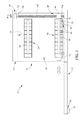
- FIG. 2 is a schematic top view of the bottom dishwasher rack of FIG. 1 illustrating the dishwasher rack in the stowed position;
- FIG. 3 is a schematic side view of the embodiment of FIG. 1 at a first height and illustrating another dishwasher rack disposed above;
- FIG. 4 is a schematic side view of the embodiment of FIG. 3 illustrating the dishwasher rack in a deployed position different from the stowed position;
- FIG. 5 is a schematic side view of the embodiment of FIG. 3 illustrating the dishwasher rack in the deployed position and at a second height;
- FIG. 6 is a schematic side view of another embodiment of the dishwasher rack illustrating another embodiment of a gear mechanism
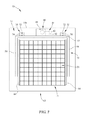
- FIG. 7 is a schematic top view of the dishwasher rack of FIG. 2 illustrating one embodiment of a guide mechanism
- FIG. 8 is a schematic top view of the embodiment of FIG. 7 illustrating the guide mechanism in another location relative to the rack support;
- FIG. 9 is a schematic top view of the dishwasher rack of FIG. 2 illustrating another embodiment of a guide mechanism.
- FIG. 10 is a schematic top view of the embodiment of FIG. 9 illustrating the guide mechanism in another location relative to the rack support.
- the embodiments discussed hereinafter will focus on the implementation of the hereinafter-described techniques within a front-load residential dish washing machine such as dish washing appliance 10 , such as the type that may be used in single-family or multi-family dwellings, or in other similar applications.
- the herein-described apparatus and techniques may also be used in connection with other types of dish washing machines in some embodiments.
- the herein-described apparatus and techniques may be used in commercial applications in some embodiments.
- the herein-described apparatus and techniques may be used in connection with other dish washing machine configurations, and even other appliances, such as, for example, ovens, refrigerators, and the like.
- Embodiments for a dish washing machine are shown herein for ease of understanding.
- a front-load dish washing machine that includes a front-mounted door 12 in a cabinet or housing 11 that provides access to at least one horizontally-oriented dishwasher rack 20 housed within the cabinet or housing 11 may be used. More specifically, the dishwasher rack 20 may be housed in a dishwasher tub 14 .
- Implementation of the herein-described apparatus and techniques within a variety of appliances would be well within the abilities of one of ordinary skill in the art having the benefit of the instant disclosure, so the invention is not limited to the front-load dish washing implementation discussed further herein.
- FIG. 1 illustrates an example dish washing appliance 10 in which the various technologies and techniques described herein may be implemented.
- Dish washing appliance 10 is a front-load dish washing machine, and as such may include a front-mounted door 12 ( FIGS. 1 and 3 ) defining an opening 13 that provides access to a horizontally-oriented dishwasher tub 14 .
- the door 12 may be coupled with a cabinet or housing 11 that may house the dishwasher tub 14 .
- Door 12 is generally hinged along a front or front edge of the housing 11 adjacent the opening 13 and is pivotable between the open position illustrated in FIG. 1 and a closed position (not shown).
- control panel 18 may include various types of input and/or output devices, including various knobs, buttons, lights, switches, textual and/or graphical displays, touch screens, etc. through which a user may configure one or more settings and start and stop the dishwasher rack cycle or movement as described herein.
- control panel 18 may be included with the dishwasher rack 20 , on the interior or exterior of the door, and/or adjacent the rack within the opening of the dish washing machine.
- portions of the controls may be accessible when the door 12 is in the open position.
- the one or more racks 20 may raise and/or lower by proximity of one or more users and/or by a one or more gestures or bodily movement relative to the rack and/or portions of the dish washing machine.
- the one or more dishwasher racks 20 may be moveable or positionable relative to the dish washing appliance 10 between a stowed or un-deployed position ( FIGS. 1, 3, and 7-10 ) and a deployed or different position ( FIGS. 4-6 ). At least one of the stowed positions of the dishwasher rack 20 may be used when one or more of the washing cycles is in operation to wash objects in the wash cavity 15 .
- the deployed position may be one or more positions different from one or more of the stowed positions.
- One deployed position may be a position to dry, load, and/or unload dishes, utensils, or the like.
- the one or more dishwasher racks 20 may travel in one or more horizontal planes between the stowed and deployed positions.
- the horizontal planes may be into and/or out of the wash cavity 15 defined by the dishwasher tub 14 .
- the wash cavity 15 may be defined by one or more walls, not limited to the rear wall 14 a , of the dishwasher tub 14 .
- the substantially linear movement of the dishwasher rack may occur along one horizontal plane as shown in one embodiment, the path of travel may be in a variety of angles, curves, and/or height positions in one or both the directions into or out of a position.
- the one or more dishwasher racks 20 may be positionable or operable between one or more vertical positions or heights.
- the dishwasher rack 20 may be positionable, raised and/or lowered, between a variety of height positions or range of height positions.
- the height positions may include at least a first height and at least a second height.
- the second height ( FIGS. 1 and 5 ) may be at a vertical elevation higher than the first height ( FIG. 4 ).
- the dishwasher rack 20 may be deployed and/or stowed when the rack is in any of the one or more heights.
- the dishwasher rack 20 may be deployed and/or stowed while the dishwasher rack is being raised and/or lowered between one or more positions. In some embodiments as shown in FIGS.
- the dishwasher rack 20 may be raised and/or lowered between one or more heights when the dishwasher rack is in the deployed position. In some embodiments, the dishwasher rack 20 may be raised and/or lowered between one or more heights when the dishwasher rack is in the stowed position. Further the range of travel of the rack or portions of a rack may include a variety of distances and still be within the scope of the invention. For example in some various embodiments, the dishwasher rack distance of vertical travel in one or more stowed and/or deployed positions may be dependent on, but is not limited to, factors such as the location relative to another rack, the load conditions of one or more racks (i.e. dishes loaded and/or unloaded, size and/or shape of dishes), the desired height based upon one or more user preferences(i.e. on height of the user and/or desired height of the rack based on the contents within the rack to be unloaded).
- factors such as the location relative to another rack, the load conditions of one or more racks (i.e. dishes loaded and/or unloaded, size and/
- one or more dishwasher racks 20 may be power driven by a variety of devices or drive mechanisms 30 between the variety of heights.
- one or more motors 32 may be used to raise and/or lower the one or more dishwasher racks 20 .
- the motor 32 may drive the dishwasher rack 20 between the variety of heights, such as but not limited to, the first height and the second height.
- One embodiment may include an electric motor as shown with a drive shaft 34 projecting therefrom. The electric motor's rotation may correspond to the appropriate linear travel and/or direction of the dishwasher rack 20 between a variety of vertical position along any number of horizontal positions between the stowed and deployed positions.
- actuators i.e. mechanical, electro-mechanical, pneumatic, hydraulic, magnetic, pressure, or the like, may be used and still be within the scope of the invention to achieve the variety of heights of the dishwasher rack.
- one embodiment of the dishwasher rack 20 may be moveable between one or more height positions.
- the dishwasher rack 20 or portions thereof, may be connected to the one or more worm screws 42 by one or more threaded members 44 .
- the worm screw 42 may be orientated in a vertical plane within the dishwasher tub 14 .
- the motor 32 is coupled to a worm screw or threaded gear 42 via the motor drive shaft 34 adjacent the rear wall 14 a .
- the threaded member 44 is connected to the dishwasher rack 20 and the worm screw 42 .
- the motor 32 may be positioned outside the dishwasher tub 14 wash cavity 15 .
- the motor 32 may be positioned at least partially or completely within the dishwasher tub 14 in some embodiments.
- the threaded member 44 may be attached to the dishwasher rack 20 such that the threaded member 44 is positionable with the rack 20 between the first height ( FIG. 4 ) and the second height ( FIG. 5 ), or variety of one or more height positions or distances. Further in some embodiments as is shown and discussed herein, one or more slides 64 may be positionable with the dishwasher rack 20 between the first height and the second height.
- the threaded member 44 is shown as a block or nut with a threaded opening receiving the worm screw 42 , a variety of threaded members may be used in different quantities, construction, shape, orientations and still operably engage the worm screw 42 .
- Rotation of the motor 32 may rotate the drive shaft 34 and worm screw 42 clockwise and/or counterclockwise. Because the threaded member 44 is fixed to the dishwasher rack 20 , rotation of the worm screw 42 moves (i.e. but not limited to linearly) the threaded member 44 and dishwasher rack 20 between a variety of vertical positions in any number of horizontal positions between the stowed and deployed positions, depending on the direction of rotation of the worm screw 42 .
- the electric motor 32 may be engaged in the appropriate rotational direction by a controller in some embodiments.
- the dishwasher rack 20 may be connected to the threaded member 44 by a rack support 50 .
- the rack support 50 may be fixed to the threaded member 44 such that the rack support 50 and threaded member 44 travel vertically between various positions or heights.
- the rack support 50 may surround at least a portion of the outer periphery of the dishwasher rack 20 .
- the rack support 50 may include an elongated rear member 52 adjacent the rear wall 14 a and/or proximal end of the dishwasher rack 20 . At each end of the rear member 52 of the rack support 50 a lateral arm 54 may project from the rear member 52 towards the distal end of the dishwasher rack and/or opening 13 .
- the rack support 50 is shown as substantially U-shaped in a horizontal plane, the rack support 50 may be a variety of quantities, sizes, shapes, orientations, and constructions and still be within the scope of the invention.
- the dishwasher rack 20 may be coupled to one or more guide mechanisms 70 , 170 .
- the guide mechanism may be positioned at one or more locations to guide and support the vertical movement or height position of the dishwasher rack 20 .
- the one or more guide mechanisms 70 , 170 may be positioned at the rear member 52 .
- the guide mechanisms 70 , 170 may be positioned anywhere along one or more lateral arms 54 .
- the guide mechanisms may be included in one or more of the lateral arms 54 and also the rear member 52 in some embodiments.
- the guide mechanism may be a variety of quantities, sizes, orientations, positions, and constructions and still be within the scope of the invention.
- one or more guide rods 72 may be mounted vertically within the dishwasher tub 14 and at least one guide block 74 may be coupled with the rack support 50 to receive the corresponding guide rod 72 therethrough such that dishwasher rack 20 and guide block 74 may move vertically along the guide rod 72 .
- the guide mechanism 170 as shown in FIGS.
- vertically orientated and elongated guide tracks or rails 172 define a receiving slot to receive a corresponding guide protrusion or projection 174 from the rack support 50 to support and guide the dishwasher rack's vertical movement and may reduce the lateral movement thereof.
- the dishwasher rack 20 may be self-locking in one or more height positions.
- the interaction of the geometry of the worm screw 42 and threaded member 44 self-locks such that the dishwasher rack 20 may not be raised and/or lowered unless the worm screw 42 is being rotated.
- the guide mechanism 70 and/or rack support 50 may include self-locking features that engage and/or disengage operably by the user and/or controller.
- a locking tab, clip, and/or releasable catch may be used.
- one or more locks may engage if the rack 20 is loaded or of a particular or sufficient first weight, and/or may disengage if the dishwasher rack 20 is unloaded or of a particular or sufficient second weight.
- the first weight may be larger than the second weight in some embodiments.
- the one or more dishwasher racks 20 may include a variety of attachments 60 to deploy and/or retract the dishwasher racks relative to the dishwasher tub 14 and/or rack support 50 .
- the attachment 60 is in the form of one or more slides or rails 64 .
- a variety of attachments 60 may be used such, as but not limited to, wheels 62 .
- One or more wheels 62 may allow the dishwasher rack 20 to be in rolling contact with the rack support 50 .
- Wheels 62 may be used in combination with rails 64 in various embodiments. In some embodiments as shown in FIGS.
- the dishwasher rack 20 may include one or more rails or slides 64 engaging the rack support 50 allowing the linear or horizontal travel of the dishwasher rack between the stowed position and the deployed position.
- the engagement between the rack support 50 and the dishwasher rack 20 is shown in one embodiment, a variety of attachments and/or mechanisms may be used to allow movement of the dishwasher rack relative to the dishwasher tub, threaded member 44 , and/or rack support 50 and still be within the scope of the invention disclosed herein.
- the drive mechanism 30 , gear mechanisms 40 , guide mechanisms 70 , 170 , and/or one or more threaded members 44 may be positioned adjacent the rear portion of the dishwasher tub 14 .
- the worm screw 42 , the threaded member 44 , and/or motor 32 may be positioned adjacent the rear wall 14 a of the dishwasher tub 14 that defines a portion of the wash cavity 15 . This location distal from the opening 13 may reduce contact with the user.
- the gear mechanism 40 , rack support 50 , threaded member 44 , and/or guide mechanism 70 , 170 might not project out of the opening 13 in some embodiments. As is shown at least in FIGS.
- the worm screw 42 is positioned within the wash cavity 15 , or more specifically in some embodiments between the dishwasher rack 20 and the rear wall 14 a . It should be understood that the one or more worm screws 42 and/or threaded members 44 may be positioned at a variety of locations within in the dishwasher tub 14 spaced away from the opening 13 and/or at various positions relative to the dishwasher rack 20 .
- the dishwasher tub 14 may include two or more racks 20 .
- the dishwasher rack 20 with lift system is the bottom rack of the appliance 10 as shown in FIGS. 1-5 , it should be understood that the lift system may be used with the upper rack, alone or combined with the lower rack.
- the lower dishwasher rack 20 may include wheels 62 , if used, and be raised and/or lowered. In some embodiments, wheels 62 may not be used.
- the upper rack 20 may include slides 64 as shown and may or may not be raised and/or lower in some embodiments. However, it should be understood that the lower and/or upper rack, or respective portions thereof, may be lowered or raised in various embodiments hereof.
- one or more racks or portions thereof may be raised and/or lowered together and/or separately. Further, one or more racks 20 or portions of one or more racks may be driven between heights independently and/or dependently from another rack and/or portions of racks thereof. For example, one or more rack portions may move vertically relative to the remaining rack portions before and/or after the remaining portions travel. Further, some dishwasher racks may move before and/or after another rack to correspond to a user's preference, for example when loading and/or unloading the one or more dishwasher racks of the appliance 10 . In should be understood that in some embodiments, the one or more dishwasher racks may travel between a first height and second height when the door 12 is in a closed and/or open position.
- the gear mechanism 40 between the drive mechanism 30 and dishwasher rack 20 may be used to position the dishwasher rack 20 between the first height and the second height.
- the dishwasher rack 20 may be coupled to the motor 32 and drive shaft 34 by the gear mechanism 40 that includes a worm screw 42 and worm wheel 46 .
- the worm wheel 46 may be a gear or threaded member such that the rotation of the worm wheel 46 by the motor 32 rotates the worm screw 42 in one or more rotational directions, thereby translating the threaded member 44 and dishwasher rack 20 up and/or down in the corresponding direction along a length of the worm screw 42 .
- the dishwasher rack 20 is shown schematically in the figures, it should be understood that the dishwasher rack may be a variety of sizes, shapes, quantities, and construction and still be within the scope of the teachings herein.
- the dishwasher rack 20 may have a first portion that may move between a variety of vertical positions any number of horizontal positions between the stowed and deployed positions separately and/or together with another portion of the rack and/or other rack.
- embodiments of the dishwasher rack 20 may be operated by one or more control panels 18 .
- a control panel 18 may be outside the door 12 .
- the control panels may be inside and/or outside the door.
- the extension and/or retraction of the dishwasher rack may be selected by the user.
- the duration of travel, distance of travel, first height, second height, and one or more height positions all may be preset, depending upon characteristics of the dishwasher rack (i.e. weight, size, and/or quantity of items to be cleaned, capacity available and/or not available, loaded or unloaded conditions, or the like), or can be predetermined. Also, preprogramed cycles or modes may also be used to position the dishwasher rack.
- dish washing appliance 10 and/or dishwasher rack 20 may be, in whole or in part, under the control of a controller (not shown) that receives inputs from a number of components and drives a number of components in response thereto.
- the controller may, for example, include one or more processors and a memory (not shown) within which may be stored program code for execution by the one or more processors.
- the memory may be embedded in the controller, but may also be considered to include volatile and/or non-volatile memories, cache memories, flash memories, programmable read-only memories, read-only memories, etc., as well as memory storage physically located elsewhere from controller, e.g., in a mass storage device or on a remote computer interfaced with a controller.
- the controller may be interfaced with various components, including the aforementioned dishwasher tub 14 , dishwasher rack 20 , door 12 , drive mechanism 30 , gear mechanism 40 , guide mechanisms 70 , 170 , sensors (not shown), etc.
- the sensors may include limit switches and/or contact switches that maintain the one or more deployed and/or stowed positions while one or more vertical adjustments in height occur.
- one or more sensors may also be used to position one or more racks from encroaching into a space and/or close proximity of another rack or their respective contents.
- the use of a sensor may allow the rack to be raised and/or lowered only when the rack has reached a deployed position such as to allow the lower rack to be raised vertically without encroaching with the upper rack.
- controller may be coupled to a user interface 19 including various input/output devices such as knobs, dials, sliders, switches, buttons, lights, textual and/or graphics displays, touch screen displays, speakers, image capture devices, microphones, etc. for receiving input from and communicating with a user, e.g., as may be disposed in a control panel 18 .
- a controller may also be coupled to one or more network interfaces, e.g., for interfacing with external devices via wired and/or wireless networks such as Ethernet, Bluetooth, NFC, cellular, and other suitable networks. Additional components may also be interfaced with a controller, as will be appreciated by those of ordinary skill having the benefit of the instant disclosure.
- controller may be implemented externally from a dish washing machine, e.g., within a mobile device, a cloud computing environment, etc., such that at least a portion of the functionality described herein is implemented within the portion of the controller that is externally implemented.
- a controller may operate under the control of an operating system and may execute or otherwise rely upon various computer software applications, components, programs, objects, modules, data structures, etc.
- controller may also incorporate hardware logic to implement some or all of the functionality disclosed herein.
- the sequences of operations performed by controller to implement the embodiments disclosed herein may be implemented using program code including one or more instructions that are resident at various times in various memory and storage devices, and that, when read and executed by one or more hardware-based processors, perform the operations embodying desired functionality.
- such program code may be distributed as a program product in a variety of forms, and that the invention applies equally regardless of the particular type of computer readable media used to actually carry out the distribution, including, for example, non-transitory computer readable storage media.
- the various operations described herein may be combined, split, reordered, reversed, varied, omitted, parallelized and/or supplemented with other techniques known in the art, and therefore, the invention is not limited to the particular sequences of operations described herein.
- a reference to “A and/or B”, when used in conjunction with open-ended language such as “comprising” can refer, in one embodiment, to A only (optionally including elements other than B); in another embodiment, to B only (optionally including elements other than A); in yet another embodiment, to both A and B (optionally including other elements); etc.
- the phrase “at least one,” in reference to a list of one or more elements, should be understood to mean at least one element selected from any one or more of the elements in the list of elements, but not necessarily including at least one of each and every element specifically listed within the list of elements and not excluding any combinations of elements in the list of elements.
- This definition also allows that elements may optionally be present other than the elements specifically identified within the list of elements to which the phrase “at least one” refers, whether related or unrelated to those elements specifically identified.
- “at least one of A and B” can refer, in one embodiment, to at least one, optionally including more than one, A, with no B present (and optionally including elements other than B); in another embodiment, to at least one, optionally including more than one, B, with no A present (and optionally including elements other than A); in yet another embodiment, to at least one, optionally including more than one, A, and at least one, optionally including more than one, B (and optionally including other elements); etc.
Landscapes
- Washing And Drying Of Tableware (AREA)
Abstract
Description
- This application is a continuation of U.S. patent application Ser. No. 15/391,733, filed on Dec. 27, 2016, which is related to the following application, which was filed on Dec. 27, 2016, and assigned to the same assignees as the related application: U.S. patent application Ser. No. 15/391,738 entitled “DISHWASHER RACK SYSTEM.” The disclosure of this application is incorporated by reference herein.
- The present embodiments relate to an appliance rack or shelf with particular embodiments shown for a dishwasher rack for a dishwasher appliance.
- Typical dishwasher racks, if adjustable in height at all, may include a multi-bar linkage to mechanically assist the user to swing the bottom rack out and up from the dishwasher tub. However, this structure often may contain several pinch points within the linkage, and unexpected movement may also occur. Thus, there is a need for the dishwasher rack to be capable of adjustment in the vertical direction while maintaining the ability to extend out of and/or retract into the dishwasher tub.
- In some embodiments of the invention, for example, a dish washing appliance may include a dishwasher tub defining a wash cavity. The appliance may include one or more dishwasher racks positioned within the wash cavity of the dishwasher tub. Moreover in some embodiments, at least one of the dishwasher racks may be moveable between a stowed position and a deployed position, wherein the deployed position may be different from the stowed position. In various embodiments, the appliance may include at least one threaded member. Further, in some embodiments, the appliance may include one or more slides coupling at least one dishwasher rack to at least one threaded member. The appliance may include at least one motor. In some embodiments, the appliance may include at least one worm screw located within the wash cavity and operably coupled to at least one motor. In various embodiments, at least one threaded member and at least one dishwasher rack may be connected to at least one worm screw. Further, at least one threaded member, one of more slides, and at least one dishwasher rack may be positionable between a first height and a second height along a length of at least one worm screw when at least one dishwasher rack is in the deployed position. Further, the second height may be at a higher vertical elevation than the first height.
- In some embodiments, at least one threaded member and at least one worm screw may be positioned adjacent a rear wall of the dishwasher tub. Further in some embodiments, at least one worm screw may be located between at least one rack and the rear wall of the dishwasher tub. In various embodiments, at least one dishwasher rack may be in the stowed position in at least one height between the first height and the second height along at least one worm screw. In some embodiments, a rack support may be fixed to at least one threaded member. Further, the rack support may include one or more slides. In some embodiments, one or more guide mechanisms may be between the rack support and the dishwasher tub. Further, in some embodiments, one or more guide mechanisms may be adjacent a rear wall of the dishwasher tub.
- In some embodiments, a dish washing appliance may include a dishwasher tub defining a wash cavity. Further, the dishwasher tub may include a rear wall. Moreover, in some embodiments, the appliance may include one or more dishwasher racks. Moreover, at least one of the dishwasher racks may be positionable within the wash cavity of the dishwasher tub. In some embodiments, the appliance may include at least one threaded member. In some embodiments, the appliance may include at least one motor. In some embodiments, the appliance may include at least one worm screw positioned within the wash cavity between at least one dishwasher rack and the rear wall. Moreover, at least one worm screw may be operably coupled to at least one motor. In various embodiments, at least one threaded member and at least one dishwasher rack may be connected to at least one worm screw. Further, at least one threaded member and at least one dishwasher rack may be positionable between a first height and a second height along at least one worm screw. Further in some embodiments, the second height is at a higher vertical elevation than the first height. In various embodiments, at least one dishwasher rack is positionable between a stowed position and a deployed position when at least one threaded member and at least one dishwasher rack are capable of being positioned at one or more heights between the first height and the second height. Further, the deployed position is different from the stowed position.
- In addition, in some embodiments, at least one motor may be positioned outside the wash cavity. In various embodiments, the one or more heights include at least one of the first height and the second height. Further in some embodiments, at least one dishwasher rack may include one or more slides engaging at least one dishwasher rack to at least one threaded member. In addition in some embodiments, a rack support may be fixed to at least one threaded member. Further, the rack support may include the one or more slides. In various embodiments, one or more guide mechanisms may be between the rack support and the dishwasher tub. In some embodiments, the one or more guide mechanisms may be adjacent the rear wall of the dishwasher tub. Moreover in some embodiments, at least one threaded member and at least one dishwasher rack may be positionable between the first height and the second height along at least one worm screw when in the deployed position.
- In various embodiments, a dish washing appliance may include a dishwasher tub that may include at least a rear wall therein defining a wash cavity. In some embodiments, the appliance may include one or more dishwasher racks. Further in some embodiments, at least one of the dishwasher racks may be positioned within the wash cavity of the dishwasher tub. In addition in some embodiments, the appliance may include at least one threaded member. In addition in some embodiments, the appliance may include at least one motor. Moreover in some embodiments, the appliance may include at least one worm screw operably coupled to at least one motor. In various embodiments, at least one worm screw may be fixedly positioned in a substantially vertical orientation adjacent the rear wall of the dishwasher tub. In addition, in some embodiments, at least one threaded member and at least one dishwasher rack may be connected to at least one worm screw. Further in some embodiments, at least one threaded member and at least one dishwasher rack may be positionable between a first height and a second height along at least one worm screw. In various embodiments, the second height may be at a higher vertical elevation than the first height. In addition in some embodiments, at least one dishwasher rack may be positionable between a stowed position and a deployed position when at least one threaded member and at least one dishwasher rack are at one or more heights between the first height and the second height. Further, in various embodiments the deployed position may be different from the stowed position.
- In addition, in some embodiments, the one or more dishwasher racks may be an upper dishwasher rack positioned above at least one dishwasher rack. In various embodiments, at least one worm screw may be located within the wash cavity of the dishwasher tub. Further in some embodiments, at least one dishwasher rack may include one or more slides engaging at least one dishwasher rack to at least one threaded member. In some embodiments, a rack support may be fixed to at least one threaded member. Further, the rack support may include the one or more slides. In addition in some embodiments, one or more guide mechanisms may be between the rack support and the dishwasher tub. In various embodiments, at least one threaded member and at least one dishwasher rack may be positionable between the first height and the second height along at least one worm screw when in the deployed position.
- These and other advantages and features, which characterize several embodiments, are set forth in the claims annexed hereto and form a further part hereof. However, for a better understanding of the embodiments, and of their advantages and objectives, reference should be made to the drawings and to the accompanying description, in which there are described example embodiments. This summary is merely provided to introduce a selection of concepts that are further described below in the detailed description, and is not intended to identify key or essential features of the claimed subject matter, nor is it intended to be used to limit the scope of the claimed subject matter, nor to define the field of endeavor.
- In the drawings, like reference characters generally refer to the same parts throughout the different views. Also, the drawings are not necessarily to scale, emphasis instead generally being placed upon illustrating the principles of the invention.
-
FIG. 1 is a perspective view of one embodiment of a bottom dishwasher rack illustrating at least one raised height position, with portions of the housing, upper rack, and dishwasher tub removed; -
FIG. 2 is a schematic top view of the bottom dishwasher rack ofFIG. 1 illustrating the dishwasher rack in the stowed position; -
FIG. 3 is a schematic side view of the embodiment ofFIG. 1 at a first height and illustrating another dishwasher rack disposed above; -
FIG. 4 is a schematic side view of the embodiment ofFIG. 3 illustrating the dishwasher rack in a deployed position different from the stowed position; -
FIG. 5 is a schematic side view of the embodiment ofFIG. 3 illustrating the dishwasher rack in the deployed position and at a second height; -
FIG. 6 is a schematic side view of another embodiment of the dishwasher rack illustrating another embodiment of a gear mechanism; -
FIG. 7 is a schematic top view of the dishwasher rack ofFIG. 2 illustrating one embodiment of a guide mechanism; -
FIG. 8 is a schematic top view of the embodiment ofFIG. 7 illustrating the guide mechanism in another location relative to the rack support; -
FIG. 9 is a schematic top view of the dishwasher rack ofFIG. 2 illustrating another embodiment of a guide mechanism; and -
FIG. 10 is a schematic top view of the embodiment ofFIG. 9 illustrating the guide mechanism in another location relative to the rack support. - Numerous variations and modifications will be apparent to one of ordinary skill in the art, as will become apparent from the description below. Therefore, the invention is not limited to the specific implementations discussed herein.
- The embodiments discussed hereinafter will focus on the implementation of the hereinafter-described techniques within a front-load residential dish washing machine such as
dish washing appliance 10, such as the type that may be used in single-family or multi-family dwellings, or in other similar applications. However, it will be appreciated that the herein-described apparatus and techniques may also be used in connection with other types of dish washing machines in some embodiments. For example, the herein-described apparatus and techniques may be used in commercial applications in some embodiments. Moreover, the herein-described apparatus and techniques may be used in connection with other dish washing machine configurations, and even other appliances, such as, for example, ovens, refrigerators, and the like. - Embodiments for a dish washing machine are shown herein for ease of understanding. For example, a front-load dish washing machine that includes a front-mounted
door 12 in a cabinet orhousing 11 that provides access to at least one horizontally-orienteddishwasher rack 20 housed within the cabinet orhousing 11 may be used. More specifically, thedishwasher rack 20 may be housed in adishwasher tub 14. Implementation of the herein-described apparatus and techniques within a variety of appliances would be well within the abilities of one of ordinary skill in the art having the benefit of the instant disclosure, so the invention is not limited to the front-load dish washing implementation discussed further herein. - Turning now to the drawings, wherein like numbers denote like parts throughout the several views,
FIG. 1 illustrates an exampledish washing appliance 10 in which the various technologies and techniques described herein may be implemented.Dish washing appliance 10 is a front-load dish washing machine, and as such may include a front-mounted door 12 (FIGS. 1 and 3 ) defining anopening 13 that provides access to a horizontally-orienteddishwasher tub 14. Thedoor 12 may be coupled with a cabinet orhousing 11 that may house thedishwasher tub 14.Door 12 is generally hinged along a front or front edge of thehousing 11 adjacent theopening 13 and is pivotable between the open position illustrated inFIG. 1 and a closed position (not shown). Whendoor 12 is in the open position, dishes, utensils, pans, and other washable items may be inserted into and removed from the one or more dishwasher racks 20 through theopening 13 in the front of cabinet orhousing 11. Control overdish washing appliance 10, or more specifically the dishwasher racks 20, by a user is generally managed through acontrol panel 18 disposed on adoor 12 and implementing auser interface 19 for the rack, and it will be appreciated that in different designs,control panel 18 may include various types of input and/or output devices, including various knobs, buttons, lights, switches, textual and/or graphical displays, touch screens, etc. through which a user may configure one or more settings and start and stop the dishwasher rack cycle or movement as described herein. For example, thecontrol panel 18, or portions thereof, may be included with thedishwasher rack 20, on the interior or exterior of the door, and/or adjacent the rack within the opening of the dish washing machine. For example in some embodiments, portions of the controls may be accessible when thedoor 12 is in the open position. In other embodiments, the one ormore racks 20 may raise and/or lower by proximity of one or more users and/or by a one or more gestures or bodily movement relative to the rack and/or portions of the dish washing machine. - As shown in the figures, the one or more dishwasher racks 20, or portions thereof, may be moveable or positionable relative to the
dish washing appliance 10 between a stowed or un-deployed position (FIGS. 1, 3, and 7-10 ) and a deployed or different position (FIGS. 4-6 ). At least one of the stowed positions of thedishwasher rack 20 may be used when one or more of the washing cycles is in operation to wash objects in thewash cavity 15. The deployed position may be one or more positions different from one or more of the stowed positions. One deployed position may be a position to dry, load, and/or unload dishes, utensils, or the like. The one or more dishwasher racks 20 may travel in one or more horizontal planes between the stowed and deployed positions. The horizontal planes may be into and/or out of thewash cavity 15 defined by thedishwasher tub 14. Thewash cavity 15 may be defined by one or more walls, not limited to therear wall 14 a, of thedishwasher tub 14. Although the substantially linear movement of the dishwasher rack may occur along one horizontal plane as shown in one embodiment, the path of travel may be in a variety of angles, curves, and/or height positions in one or both the directions into or out of a position. - The one or more dishwasher racks 20, or portions thereof, may be positionable or operable between one or more vertical positions or heights. The
dishwasher rack 20 may be positionable, raised and/or lowered, between a variety of height positions or range of height positions. The height positions may include at least a first height and at least a second height. In some embodiments, the second height (FIGS. 1 and 5 ) may be at a vertical elevation higher than the first height (FIG. 4 ). Thedishwasher rack 20 may be deployed and/or stowed when the rack is in any of the one or more heights. Moreover in some embodiments, thedishwasher rack 20 may be deployed and/or stowed while the dishwasher rack is being raised and/or lowered between one or more positions. In some embodiments as shown inFIGS. 4 and 5 , thedishwasher rack 20 may be raised and/or lowered between one or more heights when the dishwasher rack is in the deployed position. In some embodiments, thedishwasher rack 20 may be raised and/or lowered between one or more heights when the dishwasher rack is in the stowed position. Further the range of travel of the rack or portions of a rack may include a variety of distances and still be within the scope of the invention. For example in some various embodiments, the dishwasher rack distance of vertical travel in one or more stowed and/or deployed positions may be dependent on, but is not limited to, factors such as the location relative to another rack, the load conditions of one or more racks (i.e. dishes loaded and/or unloaded, size and/or shape of dishes), the desired height based upon one or more user preferences(i.e. on height of the user and/or desired height of the rack based on the contents within the rack to be unloaded). - In some embodiments, one or more dishwasher racks 20, or portions thereof, may be power driven by a variety of devices or drive
mechanisms 30 between the variety of heights. As shown in the figures, in some embodiments one ormore motors 32 may be used to raise and/or lower the one or more dishwasher racks 20. Themotor 32 may drive thedishwasher rack 20 between the variety of heights, such as but not limited to, the first height and the second height. One embodiment may include an electric motor as shown with adrive shaft 34 projecting therefrom. The electric motor's rotation may correspond to the appropriate linear travel and/or direction of thedishwasher rack 20 between a variety of vertical position along any number of horizontal positions between the stowed and deployed positions. Although an electric motor is shown, it should be understood that a variety of actuators, i.e. mechanical, electro-mechanical, pneumatic, hydraulic, magnetic, pressure, or the like, may be used and still be within the scope of the invention to achieve the variety of heights of the dishwasher rack. - In various embodiments, the
dishwasher rack 20 may be coupled to thedrive mechanism 30 by a variety ofgear mechanisms 40. In various embodiments, thedishwasher rack 20 may include agear mechanism 40 having aworm screw 42 as shown inFIGS. 1-6 operably coupled to themotor 32. Theworm screw 42 may have a substantially vertical orientation with thehousing 11 ordishwasher tub 14. Theworm screw 42 may be fixedly positioned relative to thedishwasher tub 14, such that in some embodiments theworm screw 42 does not travel with thedishwasher rack 20 between the stowed and deployed positions. Further, in some embodiments as shown inFIG. 6 , aworm wheel 46 may be used. It should be understood that the gear mechanisms may be of a variety of quantities, sizes, orientations, positions, and constructions and still be within the scope of the invention. - As shown in
FIGS. 1, 4, and 5 , one embodiment of thedishwasher rack 20 may be moveable between one or more height positions. Thedishwasher rack 20, or portions thereof, may be connected to the one or more worm screws 42 by one or more threadedmembers 44. In some embodiments, theworm screw 42 may be orientated in a vertical plane within thedishwasher tub 14. Themotor 32 is coupled to a worm screw or threadedgear 42 via themotor drive shaft 34 adjacent therear wall 14 a. The threadedmember 44 is connected to thedishwasher rack 20 and theworm screw 42. In one embodiment shown inFIGS. 1, and 3-6 , themotor 32 may be positioned outside thedishwasher tub 14wash cavity 15. Although not shown, it is understood that themotor 32 may be positioned at least partially or completely within thedishwasher tub 14 in some embodiments. The threadedmember 44 may be attached to thedishwasher rack 20 such that the threadedmember 44 is positionable with therack 20 between the first height (FIG. 4 ) and the second height (FIG. 5 ), or variety of one or more height positions or distances. Further in some embodiments as is shown and discussed herein, one ormore slides 64 may be positionable with thedishwasher rack 20 between the first height and the second height. Although the threadedmember 44 is shown as a block or nut with a threaded opening receiving theworm screw 42, a variety of threaded members may be used in different quantities, construction, shape, orientations and still operably engage theworm screw 42. Rotation of themotor 32 may rotate thedrive shaft 34 andworm screw 42 clockwise and/or counterclockwise. Because the threadedmember 44 is fixed to thedishwasher rack 20, rotation of theworm screw 42 moves (i.e. but not limited to linearly) the threadedmember 44 anddishwasher rack 20 between a variety of vertical positions in any number of horizontal positions between the stowed and deployed positions, depending on the direction of rotation of theworm screw 42. Theelectric motor 32 may be engaged in the appropriate rotational direction by a controller in some embodiments. - As shown in the figures, in some embodiments the
dishwasher rack 20 may be connected to the threadedmember 44 by arack support 50. Therack support 50 may be fixed to the threadedmember 44 such that therack support 50 and threadedmember 44 travel vertically between various positions or heights. Therack support 50 may surround at least a portion of the outer periphery of thedishwasher rack 20. In one embodiment, therack support 50 may include an elongatedrear member 52 adjacent therear wall 14 a and/or proximal end of thedishwasher rack 20. At each end of therear member 52 of the rack support 50 alateral arm 54 may project from therear member 52 towards the distal end of the dishwasher rack and/oropening 13. Although therack support 50 is shown as substantially U-shaped in a horizontal plane, therack support 50 may be a variety of quantities, sizes, shapes, orientations, and constructions and still be within the scope of the invention. - In some embodiments as shown in
FIGS. 7-10 , thedishwasher rack 20 may be coupled to one ormore guide mechanisms dishwasher rack 20. InFIGS. 7 and 9 , the one ormore guide mechanisms rear member 52. In other embodiments as shown inFIGS. 8 and 10 , theguide mechanisms lateral arms 54. Moreover, the guide mechanisms may be included in one or more of thelateral arms 54 and also therear member 52 in some embodiments. The guide mechanism may be a variety of quantities, sizes, orientations, positions, and constructions and still be within the scope of the invention. For example in one embodiment of theguide mechanism 70 as shown inFIGS. 7 and 8 , one ormore guide rods 72 may be mounted vertically within thedishwasher tub 14 and at least oneguide block 74 may be coupled with therack support 50 to receive thecorresponding guide rod 72 therethrough such thatdishwasher rack 20 and guideblock 74 may move vertically along theguide rod 72. Moreover in various embodiments of theguide mechanism 170 as shown inFIGS. 9 and 10 , vertically orientated and elongated guide tracks orrails 172 define a receiving slot to receive a corresponding guide protrusion orprojection 174 from therack support 50 to support and guide the dishwasher rack's vertical movement and may reduce the lateral movement thereof. - In some embodiments, the
dishwasher rack 20 may be self-locking in one or more height positions. In one embodiment, the interaction of the geometry of theworm screw 42 and threadedmember 44 self-locks such that thedishwasher rack 20 may not be raised and/or lowered unless theworm screw 42 is being rotated. It is understood that a variety of self-locking mechanisms may be used to limit travel of the dishwasher rack. For example, theguide mechanism 70 and/orrack support 50 may include self-locking features that engage and/or disengage operably by the user and/or controller. For example a locking tab, clip, and/or releasable catch may be used. Moreover for example, one or more locks may engage if therack 20 is loaded or of a particular or sufficient first weight, and/or may disengage if thedishwasher rack 20 is unloaded or of a particular or sufficient second weight. The first weight may be larger than the second weight in some embodiments. - As shown in the figures, in some embodiments the one or more dishwasher racks 20 may include a variety of
attachments 60 to deploy and/or retract the dishwasher racks relative to thedishwasher tub 14 and/orrack support 50. In some embodiments as shown in the figures, theattachment 60 is in the form of one or more slides or rails 64. It should be understood that a variety ofattachments 60 may be used such, as but not limited to,wheels 62. One ormore wheels 62 may allow thedishwasher rack 20 to be in rolling contact with therack support 50.Wheels 62 may be used in combination withrails 64 in various embodiments. In some embodiments as shown inFIGS. 1, 3, and 4 , thedishwasher rack 20 may include one or more rails or slides 64 engaging therack support 50 allowing the linear or horizontal travel of the dishwasher rack between the stowed position and the deployed position. Although the engagement between therack support 50 and thedishwasher rack 20 is shown in one embodiment, a variety of attachments and/or mechanisms may be used to allow movement of the dishwasher rack relative to the dishwasher tub, threadedmember 44, and/orrack support 50 and still be within the scope of the invention disclosed herein. - In various embodiments as shown in the figures, the
drive mechanism 30,gear mechanisms 40, guidemechanisms members 44 may be positioned adjacent the rear portion of thedishwasher tub 14. Theworm screw 42, the threadedmember 44, and/ormotor 32 may be positioned adjacent therear wall 14 a of thedishwasher tub 14 that defines a portion of thewash cavity 15. This location distal from theopening 13 may reduce contact with the user. Moreover, thegear mechanism 40,rack support 50, threadedmember 44, and/orguide mechanism opening 13 in some embodiments. As is shown at least inFIGS. 1-3 , theworm screw 42 is positioned within thewash cavity 15, or more specifically in some embodiments between thedishwasher rack 20 and therear wall 14 a. It should be understood that the one or more worm screws 42 and/or threadedmembers 44 may be positioned at a variety of locations within in thedishwasher tub 14 spaced away from theopening 13 and/or at various positions relative to thedishwasher rack 20. - In some embodiments of the
dish washing appliance 10 as shown inFIGS. 1 and 3-5 , thedishwasher tub 14 may include two or more racks 20. Although in some embodiments that thedishwasher rack 20 with lift system is the bottom rack of theappliance 10 as shown inFIGS. 1-5 , it should be understood that the lift system may be used with the upper rack, alone or combined with the lower rack. Thelower dishwasher rack 20 may includewheels 62, if used, and be raised and/or lowered. In some embodiments,wheels 62 may not be used. Theupper rack 20 may includeslides 64 as shown and may or may not be raised and/or lower in some embodiments. However, it should be understood that the lower and/or upper rack, or respective portions thereof, may be lowered or raised in various embodiments hereof. Moreover, one or more racks or portions thereof may be raised and/or lowered together and/or separately. Further, one ormore racks 20 or portions of one or more racks may be driven between heights independently and/or dependently from another rack and/or portions of racks thereof. For example, one or more rack portions may move vertically relative to the remaining rack portions before and/or after the remaining portions travel. Further, some dishwasher racks may move before and/or after another rack to correspond to a user's preference, for example when loading and/or unloading the one or more dishwasher racks of theappliance 10. In should be understood that in some embodiments, the one or more dishwasher racks may travel between a first height and second height when thedoor 12 is in a closed and/or open position. - As shown in
FIG. 6 , another embodiment of thegear mechanism 40 between thedrive mechanism 30 anddishwasher rack 20 may be used to position thedishwasher rack 20 between the first height and the second height. Thedishwasher rack 20 may be coupled to themotor 32 and driveshaft 34 by thegear mechanism 40 that includes aworm screw 42 andworm wheel 46. Theworm wheel 46 may be a gear or threaded member such that the rotation of theworm wheel 46 by themotor 32 rotates theworm screw 42 in one or more rotational directions, thereby translating the threadedmember 44 anddishwasher rack 20 up and/or down in the corresponding direction along a length of theworm screw 42. - Although the
dishwasher rack 20 is shown schematically in the figures, it should be understood that the dishwasher rack may be a variety of sizes, shapes, quantities, and construction and still be within the scope of the teachings herein. For example, thedishwasher rack 20 may have a first portion that may move between a variety of vertical positions any number of horizontal positions between the stowed and deployed positions separately and/or together with another portion of the rack and/or other rack. - In operation, embodiments of the
dishwasher rack 20 may be operated by one ormore control panels 18. As is shown in the embodiments, acontrol panel 18 may be outside thedoor 12. However, the control panels may be inside and/or outside the door. In use, the extension and/or retraction of the dishwasher rack may be selected by the user. The duration of travel, distance of travel, first height, second height, and one or more height positions all may be preset, depending upon characteristics of the dishwasher rack (i.e. weight, size, and/or quantity of items to be cleaned, capacity available and/or not available, loaded or unloaded conditions, or the like), or can be predetermined. Also, preprogramed cycles or modes may also be used to position the dishwasher rack. - It should be understood that in some embodiments,
dish washing appliance 10 and/ordishwasher rack 20 may be, in whole or in part, under the control of a controller (not shown) that receives inputs from a number of components and drives a number of components in response thereto. The controller may, for example, include one or more processors and a memory (not shown) within which may be stored program code for execution by the one or more processors. The memory may be embedded in the controller, but may also be considered to include volatile and/or non-volatile memories, cache memories, flash memories, programmable read-only memories, read-only memories, etc., as well as memory storage physically located elsewhere from controller, e.g., in a mass storage device or on a remote computer interfaced with a controller. - The controller may be interfaced with various components, including the
aforementioned dishwasher tub 14,dishwasher rack 20,door 12,drive mechanism 30,gear mechanism 40, guidemechanisms user interface 19 including various input/output devices such as knobs, dials, sliders, switches, buttons, lights, textual and/or graphics displays, touch screen displays, speakers, image capture devices, microphones, etc. for receiving input from and communicating with a user, e.g., as may be disposed in acontrol panel 18. In some embodiments, a controller may also be coupled to one or more network interfaces, e.g., for interfacing with external devices via wired and/or wireless networks such as Ethernet, Bluetooth, NFC, cellular, and other suitable networks. Additional components may also be interfaced with a controller, as will be appreciated by those of ordinary skill having the benefit of the instant disclosure. Moreover, in some embodiments, at least a portion of controller may be implemented externally from a dish washing machine, e.g., within a mobile device, a cloud computing environment, etc., such that at least a portion of the functionality described herein is implemented within the portion of the controller that is externally implemented. - In some embodiments, a controller may operate under the control of an operating system and may execute or otherwise rely upon various computer software applications, components, programs, objects, modules, data structures, etc. In addition, controller may also incorporate hardware logic to implement some or all of the functionality disclosed herein. Further, in some embodiments, the sequences of operations performed by controller to implement the embodiments disclosed herein may be implemented using program code including one or more instructions that are resident at various times in various memory and storage devices, and that, when read and executed by one or more hardware-based processors, perform the operations embodying desired functionality. Moreover, in some embodiments, such program code may be distributed as a program product in a variety of forms, and that the invention applies equally regardless of the particular type of computer readable media used to actually carry out the distribution, including, for example, non-transitory computer readable storage media. In addition, it will be appreciated that the various operations described herein may be combined, split, reordered, reversed, varied, omitted, parallelized and/or supplemented with other techniques known in the art, and therefore, the invention is not limited to the particular sequences of operations described herein.
- While several embodiments have been described and illustrated herein, those of ordinary skill in the art will readily envision a variety of other means and/or structures for performing the function and/or obtaining the results and/or one or more of the advantages described herein, and each of such variations and/or modifications is deemed to be within the scope of the embodiments described herein. More generally, those skilled in the art will readily appreciate that all parameters, dimensions, materials, and configurations described herein are meant to be exemplary and that the actual parameters, dimensions, materials, and/or configurations will depend upon the specific application or applications for which the teachings is/are used. Those skilled in the art will recognize, or be able to ascertain using no more than routine experimentation, many equivalents to the specific embodiments described herein. It is, therefore, to be understood that the foregoing embodiments are presented by way of example only and that, within the scope of the appended claims and equivalents thereto, embodiments may be practiced otherwise than as specifically described and claimed. Embodiments of the present disclosure are directed to each individual feature, system, article, material, and/or method described herein. In addition, any combination of two or more such features, systems, articles, materials, and/or methods, if such features, systems, articles, materials, and/or methods are not mutually inconsistent, is included within the scope of the present disclosure.
- All definitions, as defined and used herein, should be understood to control over dictionary definitions, definitions in documents incorporated by reference, and/or ordinary meanings of the defined terms.
- The indefinite articles “a” and “an,” as used herein in the specification and in the claims, unless clearly indicated to the contrary, should be understood to mean “at least one.”
- The phrase “and/or,” as used herein in the specification and in the claims, should be understood to mean “either or both” of the elements so conjoined, i.e., elements that are conjunctively present in some cases and disjunctively present in other cases. Multiple elements listed with “and/or” should be construed in the same fashion, i.e., “one or more” of the elements so conjoined. Other elements may optionally be present other than the elements specifically identified by the “and/or” clause, whether related or unrelated to those elements specifically identified. Thus, as a non-limiting example, a reference to “A and/or B”, when used in conjunction with open-ended language such as “comprising” can refer, in one embodiment, to A only (optionally including elements other than B); in another embodiment, to B only (optionally including elements other than A); in yet another embodiment, to both A and B (optionally including other elements); etc.
- As used herein in the specification and in the claims, “or” should be understood to have the same meaning as “and/or” as defined above. For example, when separating items in a list, “or” or “and/or” shall be interpreted as being inclusive, i.e., the inclusion of at least one, but also including more than one, of a number or list of elements, and, optionally, additional unlisted items. Only terms clearly indicated to the contrary, such as “only one of” or “exactly one of,” or, when used in the claims, “consisting of,” will refer to the inclusion of exactly one element of a number or list of elements. In general, the term “or” as used herein shall only be interpreted as indicating exclusive alternatives (i.e. “one or the other but not both”) when preceded by terms of exclusivity, such as “either,” “one of,” “only one of,” or “exactly one of.” “Consisting essentially of,” when used in the claims, shall have its ordinary meaning as used in the field of patent law.
- As used herein in the specification and in the claims, the phrase “at least one,” in reference to a list of one or more elements, should be understood to mean at least one element selected from any one or more of the elements in the list of elements, but not necessarily including at least one of each and every element specifically listed within the list of elements and not excluding any combinations of elements in the list of elements. This definition also allows that elements may optionally be present other than the elements specifically identified within the list of elements to which the phrase “at least one” refers, whether related or unrelated to those elements specifically identified. Thus, as a non-limiting example, “at least one of A and B” (or, equivalently, “at least one of A or B,” or, equivalently “at least one of A and/or B”) can refer, in one embodiment, to at least one, optionally including more than one, A, with no B present (and optionally including elements other than B); in another embodiment, to at least one, optionally including more than one, B, with no A present (and optionally including elements other than A); in yet another embodiment, to at least one, optionally including more than one, A, and at least one, optionally including more than one, B (and optionally including other elements); etc.
- It should also be understood that, unless clearly indicated to the contrary, in any methods claimed herein that include more than one step or act, the order of the steps or acts of the method is not necessarily limited to the order in which the steps or acts of the method are recited.
- In the claims, as well as in the specification above, all transitional phrases such as “comprising,” “including,” “carrying,” “having,” “containing,” “involving,” “holding,” “composed of,” and the like are to be understood to be open-ended, i.e., to mean including but not limited to. Only the transitional phrases “consisting of” and “consisting essentially of” shall be closed or semi-closed transitional phrases, respectively, as set forth in the United States Patent Office Manual of Patent Examining Procedures, Section 2111.03.
- It is to be understood that the embodiments are not limited in its application to the details of construction and the arrangement of components set forth in the description or illustrated in the drawings. The invention is capable of other embodiments and of being practiced or of being carried out in various ways. Unless limited otherwise, the terms “connected,” “coupled,” “in communication with,” and “mounted,” and variations thereof herein are used broadly and encompass direct and indirect connections, couplings, and mountings. In addition, the terms “connected” and “coupled” and variations thereof are not restricted to physical or mechanical connections or couplings.
- The foregoing description of several embodiments of the invention has been presented for purposes of illustration. It is not intended to be exhaustive or to limit the invention to the precise steps and/or forms disclosed, and obviously many modifications and variations are possible in light of the above teaching.
Claims (20)
Priority Applications (2)
| Application Number | Priority Date | Filing Date | Title |
|---|---|---|---|
| US15/899,029 US10299657B2 (en) | 2016-12-27 | 2018-02-19 | Dishwasher rack lift system |
| PCT/CN2019/075477 WO2019158128A1 (en) | 2016-12-27 | 2019-02-19 | Dishwasher rack lift system |
Applications Claiming Priority (2)
| Application Number | Priority Date | Filing Date | Title |
|---|---|---|---|
| US15/391,733 US9895046B1 (en) | 2016-12-27 | 2016-12-27 | Dishwasher rack lift system |
| US15/899,029 US10299657B2 (en) | 2016-12-27 | 2018-02-19 | Dishwasher rack lift system |
Related Parent Applications (1)
| Application Number | Title | Priority Date | Filing Date |
|---|---|---|---|
| US15/391,733 Continuation US9895046B1 (en) | 2016-12-27 | 2016-12-27 | Dishwasher rack lift system |
Publications (2)
| Publication Number | Publication Date |
|---|---|
| US20180177378A1 true US20180177378A1 (en) | 2018-06-28 |
| US10299657B2 US10299657B2 (en) | 2019-05-28 |
Family
ID=61188549
Family Applications (2)
| Application Number | Title | Priority Date | Filing Date |
|---|---|---|---|
| US15/391,733 Expired - Fee Related US9895046B1 (en) | 2016-12-27 | 2016-12-27 | Dishwasher rack lift system |
| US15/899,029 Active US10299657B2 (en) | 2016-12-27 | 2018-02-19 | Dishwasher rack lift system |
Family Applications Before (1)
| Application Number | Title | Priority Date | Filing Date |
|---|---|---|---|
| US15/391,733 Expired - Fee Related US9895046B1 (en) | 2016-12-27 | 2016-12-27 | Dishwasher rack lift system |
Country Status (2)
| Country | Link |
|---|---|
| US (2) | US9895046B1 (en) |
| WO (2) | WO2018120925A1 (en) |
Cited By (2)
| Publication number | Priority date | Publication date | Assignee | Title |
|---|---|---|---|---|
| WO2020119130A1 (en) | 2018-12-10 | 2020-06-18 | Foshan Shunde Midea Washing Appliances Manufacturing Co., Ltd. | Retracting dishwasher rack system |
| DE102020126359A1 (en) | 2020-10-08 | 2022-04-14 | Grass Gmbh | Drawer wall element for one drawer |
Families Citing this family (22)
| Publication number | Priority date | Publication date | Assignee | Title |
|---|---|---|---|---|
| CN107580469B (en) * | 2015-05-22 | 2020-03-17 | 伊莱克斯电器股份公司 | Mechanism for unlocking a raised lower rack of a dishwasher |
| DE102015211495B4 (en) * | 2015-06-22 | 2017-12-14 | BSH Hausgeräte GmbH | Lifting device and dishwasher |
| US9895046B1 (en) * | 2016-12-27 | 2018-02-20 | Midea Group Co., Ltd. | Dishwasher rack lift system |
| US10159398B2 (en) | 2016-12-27 | 2018-12-25 | Midea Group Co., Ltd. | Dishwasher rack system |
| US10702125B2 (en) | 2017-09-29 | 2020-07-07 | Midea Group Co., Ltd. | Retracting dishwasher rack system |
| CN108720779B (en) * | 2018-06-15 | 2023-11-14 | 辽宁科技大学 | Household dish washer |
| CN108852217A (en) * | 2018-06-20 | 2018-11-23 | 佛山市顺德区美的洗涤电器制造有限公司 | The bowl basket control method of dish-washing machine and dish-washing machine |
| CN108937805A (en) * | 2018-06-20 | 2018-12-07 | 佛山市顺德区美的洗涤电器制造有限公司 | The method and storage medium of dish-washing machine and control dish-washing machine |
| USD919203S1 (en) * | 2018-09-17 | 2021-05-11 | Lg Electronics Inc. | Dishwasher |
| USD929683S1 (en) * | 2018-09-17 | 2021-08-31 | Lg Electronics Inc. | Dishwasher |
| USD907867S1 (en) * | 2018-09-17 | 2021-01-12 | Lg Electronics Inc. | Dishwasher |
| US10405656B1 (en) * | 2018-09-27 | 2019-09-10 | Larry M. Lawrence | Drawer sliding mechanism |
| US10694923B1 (en) | 2018-12-10 | 2020-06-30 | Midea Group Co., Ltd. | Retracting dishwasher rack system |
| US11219350B2 (en) | 2018-12-10 | 2022-01-11 | Midea Group Co., Ltd. | Retracting dishwasher rack system |
| KR101953717B1 (en) * | 2019-01-10 | 2019-05-22 | (주)누마스타 | Ultrasonic Automatic Dishwasher |
| DE102019131265A1 (en) * | 2019-11-20 | 2021-05-20 | Miele & Cie. Kg | Ejection device and dishwashers with an ejection device |
| US11344179B2 (en) | 2019-12-20 | 2022-05-31 | Whirlpool Corporation | Dish treating appliance with a dish rack and rail assembly |
| CN111134590A (en) * | 2020-01-19 | 2020-05-12 | 青岛海尔洗碗机有限公司 | Dish washing machine |
| CN112022047A (en) * | 2020-09-07 | 2020-12-04 | 珠海格力电器股份有限公司 | Dish washing device |
| US11779191B2 (en) * | 2021-02-19 | 2023-10-10 | Midea Group Co., Ltd. | Wheel shelf for a dish washing appliance |
| US11796245B2 (en) * | 2021-12-13 | 2023-10-24 | Electrolux Home Products, Inc. | Swing-up storage assembly |
| US12185894B2 (en) * | 2022-04-14 | 2025-01-07 | Haier Us Appliance Solutions, Inc. | Magnetic height adjustment assembly for dishwasher racks |
Citations (3)
| Publication number | Priority date | Publication date | Assignee | Title |
|---|---|---|---|---|
| US20030004282A1 (en) * | 1999-02-05 | 2003-01-02 | Koji Kamikado | Resin composition for coating |
| US20080001821A1 (en) * | 2004-09-14 | 2008-01-03 | Akira Tanaka | Signal Arrival Direction Deducing Device, Signal Arrival Direction Deducing Method, and Signal Direction Deducing Program |
| WO2014102367A1 (en) * | 2012-12-31 | 2014-07-03 | Arcelik Anonim Sirketi | A dishwasher comprising a height adjustable lower rack |
Family Cites Families (72)
| Publication number | Priority date | Publication date | Assignee | Title |
|---|---|---|---|---|
| CH230457A (en) | 1955-06-13 | 1944-01-15 | La Mont Kessel Herpen Co Kg | Hot water boiler with forced circulation and forced distribution of the heat transfer medium. |
| US3466105A (en) | 1967-12-21 | 1969-09-09 | Gen Electric | Door-operated rack extending and retracting means for a front-opening appliance cabinet |
| US3726580A (en) | 1971-06-01 | 1973-04-10 | Gen Electric | Rack level adjustment apparatus in an appliance cabinet |
| US3822085A (en) | 1971-12-27 | 1974-07-02 | Gen Electric | Dishwashing machine rack level adjustment system |
| US3809450A (en) | 1971-12-27 | 1974-05-07 | Gen Electric | Rack level adjustment system in a dishwasher |
| US3892453A (en) | 1974-10-07 | 1975-07-01 | Fedders Corp | Dishrack adjustment |
| US3982801A (en) | 1975-11-17 | 1976-09-28 | General Motors Corporation | Power-operating vertically adjustable cantilever shelves for appliance cabinets |
| US4097099A (en) | 1976-12-29 | 1978-06-27 | Whirlpool Corporation | Dishwasher rack supporting and adjusting apparatus |
| US4644693A (en) | 1985-08-20 | 1987-02-24 | Wang Hong J | Electric device for opening or shutting automative doors |
| JPH0634777Y2 (en) | 1988-07-18 | 1994-09-14 | 幹生 相馬 | Dishwasher |
| US5115822A (en) * | 1991-03-20 | 1992-05-26 | Nichols Will E | Dishwasher basket assembly including lift mechanism |
| US5409309A (en) | 1993-04-19 | 1995-04-25 | Whirlpool Corporation | Dishrack motion control arrangement for a dishwasher |
| US5474378A (en) | 1993-12-03 | 1995-12-12 | Whirlpool Corporation | Adjustable support apparatus for a dishrack |
| IT235034Y1 (en) | 1994-07-15 | 2000-03-31 | Zanussi Elettrodomestici | DISHWASHER WITH HEIGHT ADJUSTABLE BASKET |
| US5657878A (en) | 1995-07-12 | 1997-08-19 | Illinois Tool Works Inc. | Adjustable height mechanism for a dishwasher rack |
| DE19756496C2 (en) | 1997-12-19 | 2000-07-06 | Dorma Gmbh & Co Kg | Swing door drive |
| US5971513A (en) * | 1998-03-19 | 1999-10-26 | Cassalia; Alan B. | Easy load extendable/retractable bottom dishwasher rack |
| US6142551A (en) | 1998-12-17 | 2000-11-07 | Delphi Technologies, Inc. | Vehicle liftgate power operating system |
| IT1313217B1 (en) | 1999-07-01 | 2002-06-17 | Candy Spa | ELEVATOR DEVICE OF THE LOWER BASKET OF A DISHWASHER. |
| US6523919B1 (en) * | 1999-07-21 | 2003-02-25 | Switchboard | Filing cabinet having vertically extensible drawers |
| US7370983B2 (en) | 2000-03-02 | 2008-05-13 | Donnelly Corporation | Interior mirror assembly with display |
| IT1320650B1 (en) | 2000-03-29 | 2003-12-10 | Eltek Spa | DEVICE DISPENSER OF WASHING AGENTS FOR A DOMESTIC WASHING MACHINE, IN PARTICULAR A DISHWASHER. |
| NZ503866A (en) | 2000-04-10 | 2003-01-31 | Fisher & Paykel Appliances Ltd | Dishwasher with sliding drawer type wash chamber(s) in cabinet with seal formed by motor driving linkages pulling top lid down onto open top(s) fo chamber(s) |
| IT1317804B1 (en) | 2000-06-05 | 2003-07-15 | Candy Spa | DISHWASHER WITH HEIGHT-ADJUSTABLE BASKET |
| US6247771B1 (en) * | 2000-08-18 | 2001-06-19 | Evelyn J. Miller | Lower rack lifting device for a dishwasher |
| US8225458B1 (en) | 2001-07-13 | 2012-07-24 | Hoffberg Steven M | Intelligent door restraint |
| US6755490B2 (en) | 2001-08-30 | 2004-06-29 | Maytag Corporation | Dishwasher with adjustable rack |
| KR100457587B1 (en) | 2002-11-28 | 2004-11-17 | 엘지전자 주식회사 | dish washer |
| KR20040076668A (en) | 2003-02-26 | 2004-09-03 | 삼성전자주식회사 | Dishwasher |
| US20040244825A1 (en) | 2003-06-06 | 2004-12-09 | Ashton Robert H. | Dishwasher with drawer lifting mechanism |
| SE0401122D0 (en) * | 2004-04-29 | 2004-04-29 | Electrolux Home Prod Corp | Basket lifting arrangement for a dishwasher |
| KR100652583B1 (en) * | 2004-07-29 | 2006-12-06 | 엘지전자 주식회사 | Refrigerator with basket lift |
| KR100690647B1 (en) * | 2004-07-29 | 2007-03-09 | 엘지전자 주식회사 | Refrigerator with basket lift |
| US8303053B2 (en) | 2004-09-30 | 2012-11-06 | Easy Lift, Llc | Shelf extending and lifting system |
| US7621605B2 (en) * | 2004-09-30 | 2009-11-24 | Easy Lift Llc | Shelf extending and lifting system |
| DE102005010616A1 (en) * | 2005-03-08 | 2006-09-14 | BSH Bosch und Siemens Hausgeräte GmbH | Dishwasher with a storage container |
| KR100662406B1 (en) * | 2005-04-19 | 2007-01-02 | 엘지전자 주식회사 | Refrigerator |
| US20140227411A1 (en) | 2005-08-08 | 2014-08-14 | Ron's Enterprise, Inc. | Device to efficiently cook foods using liquids and hot vapors |
| DE102005057148A1 (en) * | 2005-11-30 | 2007-06-06 | BSH Bosch und Siemens Hausgeräte GmbH | Kitchen appliance with height-adjustable shelf |
| US7628461B2 (en) * | 2006-07-20 | 2009-12-08 | Maytag Corporation | Bottom mount refrigerator having an elevating freezer basket |
| US7731805B2 (en) | 2006-11-30 | 2010-06-08 | General Electric Company | Dishwasher rack lift system |
| KR101362377B1 (en) * | 2007-02-26 | 2014-02-12 | 삼성전자주식회사 | Variable shelf assembly and refrigerator having the same |
| JP4280783B2 (en) | 2007-06-19 | 2009-06-17 | シャープ株式会社 | Door-opening and closing method and apparatus for drawer-type cooking device |
| ITTO20070598A1 (en) | 2007-08-10 | 2009-02-11 | Eltek Spa | DISPENSER DEVICE, PARTICULARLY FOR HOUSEHOLD EQUIPMENT |
| KR20090025076A (en) * | 2007-09-05 | 2009-03-10 | 엘지전자 주식회사 | Rack unit of dishwasher |
| US8061790B2 (en) | 2007-12-20 | 2011-11-22 | General Electric Company | Powered drawer for an appliance |
| US8067915B2 (en) | 2008-12-31 | 2011-11-29 | General Electric Company | Electronic control circuit for a powered appliance drawer |
| DE202009004771U1 (en) * | 2009-04-30 | 2010-09-09 | Paul Hettich Gmbh & Co. Kg | Device for adjusting the height of a guided in a household appliance via at least one pullout guide tray |
| KR20110024883A (en) | 2009-09-03 | 2011-03-09 | 삼성전자주식회사 | Automatic door opening and closing device and refrigerator having same |
| US8852351B2 (en) * | 2010-10-20 | 2014-10-07 | Whirlpool Corporation | Dishwasher with wash load detection |
| US9596975B2 (en) * | 2011-05-18 | 2017-03-21 | Whirlpool Corporation | Height adjuster mechanism for a dishwasher dish rack |
| US8813766B2 (en) | 2011-05-18 | 2014-08-26 | Whirlpool Corporation | Height adjuster mechanism for a dishwasher dish rack |
| US9462926B2 (en) | 2011-11-23 | 2016-10-11 | Whirlpool Corporation | System for establishing communication between a user interface and a controller of a dishwasher |
| US9282877B2 (en) * | 2012-03-21 | 2016-03-15 | Whirlpool Corporation | Dishwasher with a pivot system for a dish rack |
| US9445707B2 (en) * | 2012-07-11 | 2016-09-20 | Carol Hexem | Dishwasher with permanent storage compartment |
| DE102012107993A1 (en) * | 2012-08-29 | 2014-03-06 | Paul Hettich Gmbh & Co. Kg | Sliding swivel mechanism of a shelf of a furniture, furniture and dishwasher |
| US9510676B2 (en) * | 2012-11-15 | 2016-12-06 | Bsh Home Appliances Corporation | Appliance height adjusting assembly |
| DE202012104492U1 (en) | 2012-11-20 | 2014-02-25 | Pas Deutschland Gmbh | detergent dispenser |
| US20140326794A1 (en) | 2013-01-30 | 2014-11-06 | Adjustavent, Llc | Adjustable register vent and grill assembly designed to fit all size standard air distribution boot openings |
| CA2844295A1 (en) | 2013-03-01 | 2014-09-01 | John Palmer Martin | Bottom-loading cooking appliance |
| US9377238B2 (en) * | 2013-03-14 | 2016-06-28 | Electrolux Home Products, Inc. | Refrigerator with a scissor-type lift mechanism |
| US20150108162A1 (en) | 2013-10-22 | 2015-04-23 | Blue Matrix Labs, Llc | Foodstuff packages and related apparatus, systems, and methods |
| DE102013226910A1 (en) * | 2013-12-20 | 2015-06-25 | BSH Hausgeräte GmbH | Lifting device and water-conducting household appliance |
| WO2015185230A1 (en) | 2014-06-05 | 2015-12-10 | Arcelik Anonim Sirketi | A dishwasher comprising an elevating means |
| EP3085294A1 (en) * | 2015-04-24 | 2016-10-26 | BSH Hausgeräte GmbH | Lifting device and dishwasher |
| DE102015208645A1 (en) * | 2015-05-11 | 2016-11-17 | BSH Hausgeräte GmbH | Lifting device and dishwasher |
| KR101999268B1 (en) * | 2015-11-12 | 2019-07-12 | 삼성전자주식회사 | Dish Washing Machine |
| CN106691350B (en) * | 2015-11-16 | 2023-10-24 | 青岛海尔洗碗机有限公司 | Bowl basket height adjusting mechanism for dish washing machine and dish washing machine |
| US10080479B2 (en) * | 2016-01-18 | 2018-09-25 | Haier Us Appliance Solutions, Inc. | Lower rack assembly for dishwasher appliance |
| US9986888B2 (en) * | 2016-01-20 | 2018-06-05 | Haier Us Appliance Solutions, Inc. | Dishwasher rack lift mechanism |
| US10159398B2 (en) * | 2016-12-27 | 2018-12-25 | Midea Group Co., Ltd. | Dishwasher rack system |
| US9895046B1 (en) * | 2016-12-27 | 2018-02-20 | Midea Group Co., Ltd. | Dishwasher rack lift system |
-
2016
- 2016-12-27 US US15/391,733 patent/US9895046B1/en not_active Expired - Fee Related
-
2017
- 2017-09-18 WO PCT/CN2017/102135 patent/WO2018120925A1/en not_active Ceased
-
2018
- 2018-02-19 US US15/899,029 patent/US10299657B2/en active Active
-
2019
- 2019-02-19 WO PCT/CN2019/075477 patent/WO2019158128A1/en not_active Ceased
Patent Citations (3)
| Publication number | Priority date | Publication date | Assignee | Title |
|---|---|---|---|---|
| US20030004282A1 (en) * | 1999-02-05 | 2003-01-02 | Koji Kamikado | Resin composition for coating |
| US20080001821A1 (en) * | 2004-09-14 | 2008-01-03 | Akira Tanaka | Signal Arrival Direction Deducing Device, Signal Arrival Direction Deducing Method, and Signal Direction Deducing Program |
| WO2014102367A1 (en) * | 2012-12-31 | 2014-07-03 | Arcelik Anonim Sirketi | A dishwasher comprising a height adjustable lower rack |
Cited By (4)
| Publication number | Priority date | Publication date | Assignee | Title |
|---|---|---|---|---|
| WO2020119130A1 (en) | 2018-12-10 | 2020-06-18 | Foshan Shunde Midea Washing Appliances Manufacturing Co., Ltd. | Retracting dishwasher rack system |
| EP3863494A1 (en) | 2018-12-10 | 2021-08-18 | Foshan Shunde Midea Washing Appliances Manufacturing Co., Ltd. | Retracting dishwasher rack system |
| EP3863494A4 (en) * | 2018-12-10 | 2022-04-06 | Foshan Shunde Midea Washing Appliances Manufacturing Co., Ltd. | SHELF SYSTEM FOR RETRACTABLE DISHWASHER |
| DE102020126359A1 (en) | 2020-10-08 | 2022-04-14 | Grass Gmbh | Drawer wall element for one drawer |
Also Published As
| Publication number | Publication date |
|---|---|
| WO2018120925A1 (en) | 2018-07-05 |
| WO2019158128A1 (en) | 2019-08-22 |
| US9895046B1 (en) | 2018-02-20 |
| US10299657B2 (en) | 2019-05-28 |
Similar Documents
| Publication | Publication Date | Title |
|---|---|---|
| US10299657B2 (en) | Dishwasher rack lift system | |
| US10433705B2 (en) | Dishwasher rack system | |
| US11612301B2 (en) | Retracting dishwasher rack system | |
| US11317783B2 (en) | Retracting dishwasher rack system | |
| CN107105893B (en) | Sliding pivoting mechanism for a frame of a piece of furniture or a household appliance, piece of furniture and household appliance | |
| US8220472B2 (en) | Dishwasher machine comprising a storage container | |
| US11497381B2 (en) | Basket for a dish washing appliance | |
| KR20170072619A (en) | Tableware cabinet | |
| US10582828B1 (en) | Retracting dishwasher rack system | |
| US10694923B1 (en) | Retracting dishwasher rack system |
Legal Events
| Date | Code | Title | Description |
|---|---|---|---|
| FEPP | Fee payment procedure |
Free format text: ENTITY STATUS SET TO UNDISCOUNTED (ORIGINAL EVENT CODE: BIG.); ENTITY STATUS OF PATENT OWNER: LARGE ENTITY |
|
| AS | Assignment |
Owner name: MIDEA AMERICA CORPORATION, NEW JERSEY Free format text: ASSIGNMENT OF ASSIGNORS INTEREST;ASSIGNORS:WILSON, MARK W.;WETZEL, TIMOTHY MARTIN;SIGNING DATES FROM 20160413 TO 20161219;REEL/FRAME:044984/0126 Owner name: MIDEA GROUP CO., LTD., CHINA Free format text: ASSIGNMENT OF ASSIGNORS INTEREST;ASSIGNOR:MIDEA AMERICA CORPORATION;REEL/FRAME:044984/0132 Effective date: 20171219 |
|
| STPP | Information on status: patent application and granting procedure in general |
Free format text: NOTICE OF ALLOWANCE MAILED -- APPLICATION RECEIVED IN OFFICE OF PUBLICATIONS |
|
| STPP | Information on status: patent application and granting procedure in general |
Free format text: PUBLICATIONS -- ISSUE FEE PAYMENT VERIFIED |
|
| STCF | Information on status: patent grant |
Free format text: PATENTED CASE |
|
| MAFP | Maintenance fee payment |
Free format text: PAYMENT OF MAINTENANCE FEE, 4TH YEAR, LARGE ENTITY (ORIGINAL EVENT CODE: M1551); ENTITY STATUS OF PATENT OWNER: LARGE ENTITY Year of fee payment: 4 |