EP3863139A1 - Connection of laminated busbars of neighbored sections under limited rear access - Google Patents
Connection of laminated busbars of neighbored sections under limited rear access Download PDFInfo
- Publication number
- EP3863139A1 EP3863139A1 EP20155428.4A EP20155428A EP3863139A1 EP 3863139 A1 EP3863139 A1 EP 3863139A1 EP 20155428 A EP20155428 A EP 20155428A EP 3863139 A1 EP3863139 A1 EP 3863139A1
- Authority
- EP
- European Patent Office
- Prior art keywords
- rear part
- console
- holder
- front part
- conductor
- Prior art date
- Legal status (The legal status is an assumption and is not a legal conclusion. Google has not performed a legal analysis and makes no representation as to the accuracy of the status listed.)
- Granted
Links
Images




Classifications
-
- H—ELECTRICITY
- H02—GENERATION; CONVERSION OR DISTRIBUTION OF ELECTRIC POWER
- H02G—INSTALLATION OF ELECTRIC CABLES OR LINES, OR OF COMBINED OPTICAL AND ELECTRIC CABLES OR LINES
- H02G5/00—Installations of bus-bars
- H02G5/005—Laminated bus-bars
-
- H—ELECTRICITY
- H01—ELECTRIC ELEMENTS
- H01R—ELECTRICALLY-CONDUCTIVE CONNECTIONS; STRUCTURAL ASSOCIATIONS OF A PLURALITY OF MUTUALLY-INSULATED ELECTRICAL CONNECTING ELEMENTS; COUPLING DEVICES; CURRENT COLLECTORS
- H01R25/00—Coupling parts adapted for simultaneous co-operation with two or more identical counterparts, e.g. for distributing energy to two or more circuits
- H01R25/16—Rails or bus-bars provided with a plurality of discrete connecting locations for counterparts
- H01R25/161—Details
- H01R25/162—Electrical connections between or with rails or bus-bars
-
- H—ELECTRICITY
- H01—ELECTRIC ELEMENTS
- H01R—ELECTRICALLY-CONDUCTIVE CONNECTIONS; STRUCTURAL ASSOCIATIONS OF A PLURALITY OF MUTUALLY-INSULATED ELECTRICAL CONNECTING ELEMENTS; COUPLING DEVICES; CURRENT COLLECTORS
- H01R25/00—Coupling parts adapted for simultaneous co-operation with two or more identical counterparts, e.g. for distributing energy to two or more circuits
- H01R25/16—Rails or bus-bars provided with a plurality of discrete connecting locations for counterparts
-
- H—ELECTRICITY
- H02—GENERATION; CONVERSION OR DISTRIBUTION OF ELECTRIC POWER
- H02B—BOARDS, SUBSTATIONS OR SWITCHING ARRANGEMENTS FOR THE SUPPLY OR DISTRIBUTION OF ELECTRIC POWER
- H02B1/00—Frameworks, boards, panels, desks, casings; Details of substations or switching arrangements
- H02B1/20—Bus-bar or other wiring layouts, e.g. in cubicles, in switchyards
-
- H—ELECTRICITY
- H02—GENERATION; CONVERSION OR DISTRIBUTION OF ELECTRIC POWER
- H02G—INSTALLATION OF ELECTRIC CABLES OR LINES, OR OF COMBINED OPTICAL AND ELECTRIC CABLES OR LINES
- H02G5/00—Installations of bus-bars
- H02G5/007—Butt joining of bus-bars by means of a common bolt, e.g. splice joint
Definitions
- the invention is related to a conductor to electrically connect two neighbored laminated busbars of a switchgear, comprising a front part and a rear part and pressure clamps to press the front part and the rear part against said laminated busbars, wherein the front part comprises at least one front conductive bridging sheet and wherein the rear part comprises at least one rear conductive bridging sheet.
- Laminated busbars are used in switchgears to conduct electrical current.
- a laminated busbar comprises several layers of conducting sheets which are separated from each other by electrically insulating sheetlike materials.
- Laminated busbars are flat and can conduct a number of phases of electrical current, wherein the number of phases depends on the number of conducting sheets.
- Laminated busbars are shown for example in DE 10 2005 015 945 B4 .
- busbars are arranged at a rear side of a switchgear or of a switchboard or of a housing, access to those busbars may be difficult. Insofar, connecting and disconnecting of busbars may be difficult as well.
- a conductor is used to provide an electrically conductive bridge between laminated busbars of neighbored sections.
- a conductor which is also called shipping split connection by the person skilled in the art, comprises a front part and a rear part and further comprises pressure clamps.
- the front part provides a connection between the phases L1 and L2 of neighbored laminated busbars and the rear part provides a connection between the L3 phases.
- the rear part connects the L3 and L4 phases (Neutral).
- an assembly procedure using such a conductor requires at least two workers and an access from a rear side of a switchgear or switchboard.
- a switchgear or switchboard When sections are aligned and their frames are connected together, one operator holds a rear part of the conductor on the rear side of the laminated busbars and a second operator holds a front part of the conductor on the front side of the laminated busbars.
- both parts of the conductor When both parts of the conductor are in correct positions, the operator adds pressure clamps and tightens them by bolts to secure an electrically conductive connection between neighbored laminated busbars.
- the actor pulls the rear part against the force of a spring in the direction of the front part.
- a disassembling is very easy.
- the force of the spring pushes the rear part away from the front part and creates a distance between these parts and between the rear part and the laminated busbar as well.
- the rear part is pushed away from the rear side of the laminated busbar.
- the conductive bridging sheet of the rear part then is distant from an electrically contact area of an electrically conductive sheet of the laminated busbar.
- the spring is a coil spring and surrounds a guiding rod, wherein the coil spring with a first end abuts on a head of the guiding rod and abuts with the second end on a holder.
- the rear part is guided in a definite way and the laminated busbar and the rear part are protected against damages.
- the rear part is connected with a holder and is movable relative to the holder, wherein the holder is connectable by fixing means with a frame of a switchgear or of a switchboard or of a housing.
- the rear part may be part of a preassembled device, which is attached to a frame of a switchgear or of a switchboard or of a housing. Insofar a kind of preassembling of the rear part is used.
- a kind of preassembling of the conductor or shipping split connection with pressure clamps may be used, preferably into a left hand side section, before sections are aligned and connected together.
- the clamps are fixed in positions on the console by a fixing console.
- One or more fixing consoles may be screwed to the console, which bears the clamps.
- a fixing console may be arranged between two clamps and may space these clamps from each other.
- the fixing console may be made of metal.
- the rear part is part of a preassembled device, which is connected with the holder.
- the rear part may be attached to a frame of a switch-gear or of a switchboard or of a housing by the holder. No worker is necessary on the rear side of a housing or of a switchgear when the rear part and the front part are moved to the laminated busbars.
- the switchgear preferably is a low voltage switchgear.
- Fig. 7 shows a conductor 1, also called a shipping split connection, to electrically connect two neighbored laminated busbars 2a, 2b of a switchgear, comprising a front part 3 and a rear part 4 and pressure clamps 5, 6 to press the front part 3 and the rear part 4 against said laminated busbars 2a, 2b, wherein the front part 3 comprises at least one front conductive bridging sheet 3a and wherein the rear part 4 comprises at least one rear conductive bridging sheet 4a.
- Those conductive bridging sheets 3a, 4a get in overlapping contact with respective electrical contact areas 7 of the laminated busbars 2a, 2b to conduct electrical current from one laminated busbar 2a to the other laminated busbar 2b.
- the rear part 4 is movable relative to the front part 3 in the direction of the arrows of Fig. 7 , wherein the front part 3 comprises an actor 8, which is couplable with a counterpart 9 of the rear part 4 and wherein moving or acting the actor 8 moves the rear part 4 to the front part 3.
- Fig. 7 show that the clamps 5, 6 are connected with consoles 15, wherein one console 15 is connected to the front part 3 and wherein one console 15 is connected to the rear part 4.
- FIG. 7 shows an arrangement, comprising a housing with a frame 14, wherein a holder 13 is connected to the frame 14, at least on laminated busbar 2a, 2b and a conductor 1, wherein the rear part 4 is connected to the holder 13 and wherein the rear part 4 is movable relative to the holder 13 in the direction of the front part 3, namely in direction of the front side F.
- Fig. 1 shows a sheet metal console 15, which may be or is glued to a front part 3 or a rear part 4 of a shipping split connection, namely of the conductor 1 described here, wherein contact areas 15a to apply glue are provided.
- the holder 13 of the rear part 4 of the conductor 1 includes the guiding rods 12, which allows the rear part 4 of the conductor 1 to be moved in front and rear direction, and springs 11, which push the rear part 4 of the conductor 1 to the rear side R to prevent a collision with the laminated busbar 2b of the neighbor section during the alignment of the sections.
- the holder 13 of the conductor 1 can compensate vertical misalignment and can ensure a correct conductor overlap of the conductor 1 and the laminated busbars 2a, 2b.
- the front part 3 of the conductor 1 is placed with pressure plates or clamps 5 in a correct position from the section front side F, bolts 8 are inserted into clamps 5 and by tightening the bolts 8 the rear part 4 of the conductor 1 is pulled towards the laminated busbar contact areas and provides a conductive contact between neighbored laminated busbars 2a, 2b.
Landscapes
- Engineering & Computer Science (AREA)
- Power Engineering (AREA)
- Patch Boards (AREA)
Abstract
Description
- The invention is related to a conductor to electrically connect two neighbored laminated busbars of a switchgear, comprising a front part and a rear part and pressure clamps to press the front part and the rear part against said laminated busbars, wherein the front part comprises at least one front conductive bridging sheet and wherein the rear part comprises at least one rear conductive bridging sheet.
- Laminated busbars are used in switchgears to conduct electrical current. A laminated busbar comprises several layers of conducting sheets which are separated from each other by electrically insulating sheetlike materials. Laminated busbars are flat and can conduct a number of phases of electrical current, wherein the number of phases depends on the number of conducting sheets. Laminated busbars are shown for example in
DE 10 2005 015 945 B4 . - Such laminated busbars often are arranged at the rear side of a switchgear or of a switchboard or of a housing. If some sections of a switchgear or several switchgears have to be connected, different laminated busbars have to be connected to each other to conduct electrical current from one section to the other or from one switchboard to another. Each conducting sheet of a first laminated busbar has to be electrically connected to the corresponding conducting sheet of the second, neighbored laminated busbar by a so called shipping split connection, which comprises a further electrically conductive sheet acting as a link or a bridge, namely the conductive bridging sheet.
- If such laminated busbars are arranged at a rear side of a switchgear or of a switchboard or of a housing, access to those busbars may be difficult. Insofar, connecting and disconnecting of busbars may be difficult as well.
- The object of the invention therefore is to allow an electrically conductive connecting and disconnecting of laminated busbars in situations where access from a rear side of a switchgear or switchboard is limited, and to prevent damages of the laminated busbars and the switchgear or switchboard.
- The object of the invention is achieved by means of the features of
claim 1. - According to this claim the rear part is movable relative to the front part, wherein the front part comprises an actor, which is couplable with a counterpart of the rear part and wherein moving or acting the actor moves the rear part to the front part.
- According to the invention first it has been found that a conductor is used to provide an electrically conductive bridge between laminated busbars of neighbored sections. Such a conductor, which is also called shipping split connection by the person skilled in the art, comprises a front part and a rear part and further comprises pressure clamps. The front part provides a connection between the phases L1 and L2 of neighbored laminated busbars and the rear part provides a connection between the L3 phases. In case of a four pole arrangement the rear part connects the L3 and L4 phases (Neutral). When the contact areas of the conductor overlap the contact areas of the laminated busbars, a pressure is applied by tightening bolts of pressure clamps to secure an electrically conductive connection between the phases of the laminated busbars arranged in neighbored sections.
- Further it has been found, that currently, an assembly procedure using such a conductor requires at least two workers and an access from a rear side of a switchgear or switchboard. When sections are aligned and their frames are connected together, one operator holds a rear part of the conductor on the rear side of the laminated busbars and a second operator holds a front part of the conductor on the front side of the laminated busbars. When both parts of the conductor are in correct positions, the operator adds pressure clamps and tightens them by bolts to secure an electrically conductive connection between neighbored laminated busbars.
- Further, it has been found, that such a solution cannot be used if there is a limited or impossible access from the rear side of the switchgear or switchboard, which is a common situation, when switchgear sections are already installed on customer sites.
- Sometimes it is also necessary to disassemble sections on site, but without access from the rear side of the switchgear or switchboard, it would be difficult or even impossible to disassemble the conductor or shipping split connection without damage.
- The invention solves these drawbacks in that way that a rear access is not required for connecting and disconnecting laminated busbars. The invention uses a kind of preassembling of the rear part.
- Advantageously, the actor is a bolt which engages in an entry or insert nut of the rear part and meshes with a thread of the entry or insert nut. By acting, turning or moving the bolt the rear part is moved in the direction of the front part without any access to the rear side of a housing of a switchgear or switchboard.
- Further advantageously, the actor pulls the rear part against the force of a spring in the direction of the front part. Through this also a disassembling is very easy. The force of the spring pushes the rear part away from the front part and creates a distance between these parts and between the rear part and the laminated busbar as well. The rear part is pushed away from the rear side of the laminated busbar. The conductive bridging sheet of the rear part then is distant from an electrically contact area of an electrically conductive sheet of the laminated busbar.
- Advantageously, the spring is a coil spring and surrounds a guiding rod, wherein the coil spring with a first end abuts on a head of the guiding rod and abuts with the second end on a holder. Through this the rear part is guided in a definite way and the laminated busbar and the rear part are protected against damages.
- Further advantageously, the rear part is connected with a holder and is movable relative to the holder, wherein the holder is connectable by fixing means with a frame of a switchgear or of a switchboard or of a housing. Through this, the rear part may be part of a preassembled device, which is attached to a frame of a switchgear or of a switchboard or of a housing. Insofar a kind of preassembling of the rear part is used. A kind of preassembling of the conductor or shipping split connection with pressure clamps may be used, preferably into a left hand side section, before sections are aligned and connected together.
- Advantageously, the clamps are connected with a console, wherein one console is connected to the front part and/ or wherein one console is connected to the rear part. The console is a part, preassembled with clamps, which may be connected to the rear part or the front part in an easy way. Preferably the console is made of metal.
- Further advantageously, the clamps are fixed in positions on the console by a fixing console. One or more fixing consoles may be screwed to the console, which bears the clamps. A fixing console may be arranged between two clamps and may space these clamps from each other. The fixing console may be made of metal.
- Advantageously, the rear part is part of a preassembled device, which is connected with the holder. Through this, the rear part may be attached to a frame of a switch-gear or of a switchboard or of a housing by the holder. No worker is necessary on the rear side of a housing or of a switchgear when the rear part and the front part are moved to the laminated busbars.
- Further advantageously, a console is glued to the rear part and/ or a console is glued to the front part. A glue or an adhesive is easy to apply.
- Advantageously an arrangement comprises a housing with a frame, wherein a holder is connected to the frame, at least one laminated busbar and a conductor as described in this specification, wherein the rear part is connected to the holder and wherein the rear part is movable relative to the holder.
- The switchgear preferably is a low voltage switchgear.
- In the drawings:
- Fig. 1
- schematically shows a sheet metal console, which is glued to a front part or a rear part of a conductor or shipping split connection, wherein contact areas to apply glue are provided,
- Fig. 2
- shows the sheet metal console of
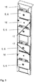
Fig. 1 , wherein clamps are placed on defined positions on the sheet metal console, - Fig. 3
- shows that the clamps are fixed in their defined positions by two fixing consoles, which may be screwed to the sheet metal console,
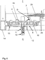
- Fig. 4
- schematically shows a rear view of the installation process of the rear part of the shipping split connection, wherein a laminated busbar is arranged in a left hand side section and wherein a holder for preassembling the rear part of the shipping split connection is provided and wherein slots for a vertical position adjustment of the holder are provided,
- Fig. 5
- schematically shows the rear view of
Fig. 4 , wherein guiding rods with springs are arranged and wherein the rear part of the shipping split connection is provided with pressure plates or clamps, - Fig. 6
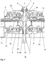
- shows a detailed sectional view of the rear part of
Fig. 5 from above, and - Fig. 7
- shows the electrical connection of two neighbored laminated busbars after section alignment, wherein bolts are tightened by turning and the rear part of the shipping split connection is pulled to the front and will create an electrically conductive bridge between the neighbored laminated busbars.
-
Fig. 7 shows aconductor 1, also called a shipping split connection, to electrically connect two neighboredlaminated busbars front part 3 and arear part 4 and pressure clamps 5, 6 to press thefront part 3 and therear part 4 against saidlaminated busbars front part 3 comprises at least one frontconductive bridging sheet 3a and wherein therear part 4 comprises at least one rearconductive bridging sheet 4a. Thoseconductive bridging sheets electrical contact areas 7 of thelaminated busbars laminated busbar 2a to the otherlaminated busbar 2b. Each respective conductive sheet of the leftlaminated busbar 2a is connected electrically by theconductor 1 with the respective conductive sheet of the rightlaminated busbar 2b, wherein those conductive sheets or better their blank contact areas face against each other and are arranged coplanar. Theconductor 1 acts as a bridge between those conductive sheets facing each other. The front side F and the rear side R of the switchgear lie on different sides of theconductor 1. - The
rear part 4 is movable relative to thefront part 3 in the direction of the arrows ofFig. 7 , wherein thefront part 3 comprises anactor 8, which is couplable with a counterpart 9 of therear part 4 and wherein moving or acting theactor 8 moves therear part 4 to thefront part 3. - The
actor 8 is a bolt which engages in an entry of therear part 4 and meshes with a thread of the entry. The entry is the said counterpart 9. The bolt is turned to move therear part 4. -
Fig. 6 shows, that theactor 8 pulls therear part 4 against the force of aspring 11 in the direction of thefront part 3. Thespring 11 creates a distance D of 20 mm between the rearconductive bridging sheet 4a and the respective contact area of aconductive sheet 10 of thelaminated busbar 2a. Thespring 11 is a coil spring and surrounds a guidingrod 12, wherein the coil spring with a first end abuts on a head of the guidingrod 12 and abuts with the second end on aholder 13. Therear part 3 is connected with theholder 13 and is movable relative to theholder 13, wherein theholder 13 is connected by fixing means with aframe 14 of a switch-gear or of a switchboard or of a housing. -
Fig. 7 show that theclamps consoles 15, wherein oneconsole 15 is connected to thefront part 3 and wherein oneconsole 15 is connected to therear part 4. -
Fig. 6 and7 show, that therear part 4 is part of a preassembled device, which is connected with theholder 13.Fig. 2 schematically shows that theclamps console 15 by fixingconsoles 16. Oneconsole 15 is glued to therear part 4 and anotherconsole 15 is glued to thefront part 3. - Insofar
Fig. 7 shows an arrangement, comprising a housing with aframe 14, wherein aholder 13 is connected to theframe 14, at least onlaminated busbar conductor 1, wherein therear part 4 is connected to theholder 13 and wherein therear part 4 is movable relative to theholder 13 in the direction of thefront part 3, namely in direction of the front side F. -
Fig. 1 shows asheet metal console 15, which may be or is glued to afront part 3 or arear part 4 of a shipping split connection, namely of theconductor 1 described here, whereincontact areas 15a to apply glue are provided. -
Fig. 2 shows thesheet metal console 15 ofFig. 1 , wherein theclamps sheet metal console 15. The pressure clamps 5, 6 are assembled to both parts,front part 3 andrear part 4 of theconductor 1, by the said sheet metal consoles 15. Asheet metal console 15 is glued to therear part 4, then the pressure clamps 5, 6 are placed and secured in position by two smaller fixing consoles 16. -
Fig. 3 shows that the fourclamps consoles 16, which may be screwed to thesheet metal console 15. Therefore theconsole 15 comprisesholes 17 for fixing the fixing consoles 16. Pressure clamps 6 with insert nuts 6a are assembled to therear part 4 of theconductor 1 and pressure clamps 5 with ahole 5a for abolt 8 are assembled to thefront part 3 of theconductor 1, as it is shown byFig. 7 . -
Fig. 4 schematically shows a rear view of an installation process of therear part 4 of theconductor 1, wherein alaminated busbar 2a is arranged in a left hand side section and wherein theholder 13 for preassembling therear part 4 of the shipping split connection is provided and whereinslots 18 for a vertical position adjustment of theholder 13 are provided. -
Fig. 5 schematically shows the rear view ofFig. 4 , wherein guidingrods 12 withsprings 11 are arranged and wherein therear part 4 of theconductor 1 is provided with pressure plates or clamps 6. Thesheet metal console 15 is assembled to the left hand side section of a switchgear arrangement. Its purpose is to hold therear part 4 of theconductor 1 with pressure clamps 6 in a correct position and to protect parts oflaminated busbars 2a and theconductor 1 from damage during a section alignment procedure. - To prevent damage of the
conductor 1 orlaminated busbars holder 13 of therear part 4 of theconductor 1 includes the guidingrods 12, which allows therear part 4 of theconductor 1 to be moved in front and rear direction, and springs 11, which push therear part 4 of theconductor 1 to the rear side R to prevent a collision with thelaminated busbar 2b of the neighbor section during the alignment of the sections. Theholder 13 of theconductor 1 can compensate vertical misalignment and can ensure a correct conductor overlap of theconductor 1 and thelaminated busbars - After alignment and connection of the sections or of the
laminated busbars front part 3 of theconductor 1 is placed with pressure plates or clamps 5 in a correct position from the section front side F,bolts 8 are inserted intoclamps 5 and by tightening thebolts 8 therear part 4 of theconductor 1 is pulled towards the laminated busbar contact areas and provides a conductive contact between neighboredlaminated busbars - The switchgear preferably is a low voltage switchgear. The switchgear comprises a housing with a
frame 14 as described above.Reference numbers 1 Conductor or shipping split connection 2a, 2b Laminated busbar (left, right) 3 Front part of 1 3a Front conductive bridging sheet 4 Rear part of 1 4a Rear conductive bridging sheet 5 Clamp of 3 5a Hole of 5 6 Clamp of 4 6a Insert nut of 6 7 Contact area of 2a or 2b 8 Bolt 9 Counterpart 10 Conductive sheet of 2a 11 Spring 12 Guiding rod 13 Holder 14 Frame 15 Console 15a Contact area to apply glue 16 Fixing console 17 Hole of 15 18 Slot of 13 or 14 F Front side R Rear side
Claims (10)
- Conductor (1) to electrically connect two neighbored laminated busbars (2a, 2b) of a switchgear, comprising a front part (3) and a rear part (4) and pressure clamps (5, 6) to press the front part (3) and the rear part (4) against said laminated busbars (2a, 2b), wherein the front part (3) comprises at least one front conductive bridging sheet (3a) and wherein the rear part (4) comprises at least one rear conductive bridging sheet (4a),
characterized in that the rear part (4) is movable relative to the front part (3), wherein the front part (3) comprises an actor (8), which is couplable with a counterpart (9) of the rear part (4) and wherein moving the actor (8) moves the rear part (4) to the front part (3). - Conductor according to claim 1, characterized in that the actor (8) is a bolt which engages in an entry or insert nut (6a) of the rear part (4) and meshes with a thread of the entry or insert nut (6a).
- Conductor according to claim 1 or 2, characterized in that the actor (8) pulls the rear part (4) against the force of a spring (11) in the direction of the front part (3).
- Conductor according to claim 3, characterized in that the spring (11) is a coil spring and surrounds a guiding rod (12), wherein the coil spring with a first end abuts on a head of the guiding rod (12) and abuts with the second end on a holder (13).
- Conductor according to one of the preceding claims, characterized in that the rear part (4) is connected with a holder (13) and is movable relative to the holder (13), wherein the holder (13) is connectable by fixing means with a frame (14) of a switchgear or of a switchboard or of a housing.
- Conductor according to one of the preceding claims, characterized in that the clamps (5, 6) are connected with a console (15), wherein one console (15) is connected to the front part (3) and/ or wherein one console (15) is connected to the rear part (4).
- Conductor according claim 6, characterized in that the clamps (5, 6) are fixed in positions on the console (15) by a fixing console (16).
- Conductor according to one of the claims 5 to 7, characterized in that the rear part (4) is part of a preassembled device, which is connected with the holder (13).
- Conductor according to one of the claims 6 to 8, characterized in that a console (15) is glued to the rear part (4) and/ or that a console (15) is glued to the front part (3).
- Arrangement, comprising a housing with a frame (14), wherein a holder (13) is connected to the frame (14), at least one laminated busbar (2a, 2b) and a conductor (1) according to one of the preceding claims, wherein the rear part (4) is connected to the holder (13) and wherein the rear part (4) is movable relative to the holder (13).
Priority Applications (2)
| Application Number | Priority Date | Filing Date | Title |
|---|---|---|---|
| EP20155428.4A EP3863139B1 (en) | 2020-02-04 | 2020-02-04 | Connection of laminated busbars of neighbored sections under limited rear access |
| CN202110152664.XA CN113285315B (en) | 2020-02-04 | 2021-02-04 | Connection of laminated busbars between adjacent sections with limited rear access |
Applications Claiming Priority (1)
| Application Number | Priority Date | Filing Date | Title |
|---|---|---|---|
| EP20155428.4A EP3863139B1 (en) | 2020-02-04 | 2020-02-04 | Connection of laminated busbars of neighbored sections under limited rear access |
Publications (2)
| Publication Number | Publication Date |
|---|---|
| EP3863139A1 true EP3863139A1 (en) | 2021-08-11 |
| EP3863139B1 EP3863139B1 (en) | 2025-11-26 |
Family
ID=69468461
Family Applications (1)
| Application Number | Title | Priority Date | Filing Date |
|---|---|---|---|
| EP20155428.4A Active EP3863139B1 (en) | 2020-02-04 | 2020-02-04 | Connection of laminated busbars of neighbored sections under limited rear access |
Country Status (2)
| Country | Link |
|---|---|
| EP (1) | EP3863139B1 (en) |
| CN (1) | CN113285315B (en) |
Cited By (1)
| Publication number | Priority date | Publication date | Assignee | Title |
|---|---|---|---|---|
| US11398718B2 (en) * | 2018-04-16 | 2022-07-26 | Abb Schweiz Ag | Apparatus for electrically interconnecting two laminated multi-phase busbars and switchgear cabinet including such an apparatus |
Citations (4)
| Publication number | Priority date | Publication date | Assignee | Title |
|---|---|---|---|---|
| WO2013166562A1 (en) * | 2012-05-10 | 2013-11-14 | Lightworker Reflections Pty Ltd | Lamellar electrical switch board |
| DE102005015945B4 (en) | 2005-04-07 | 2015-07-02 | Abb Ag | Contact device for a two- or multi-phase busbar arrangement |
| WO2019201429A1 (en) * | 2018-04-17 | 2019-10-24 | Abb Schweiz Ag | Apparatus for electrically interconnecting two laminated multi-phase busbars and switchboard arrangement including such an apparatus |
| WO2019201419A1 (en) * | 2018-04-16 | 2019-10-24 | Abb Schweiz Ag | Apparatus for electrically interconnecting two laminated multi-phase busbars and switchgear cabinet including such an apparatus |
Family Cites Families (3)
| Publication number | Priority date | Publication date | Assignee | Title |
|---|---|---|---|---|
| DE102006058778B4 (en) * | 2006-12-12 | 2013-04-25 | Rittal Gmbh & Co. Kg | cabinet arrangement |
| EP2898574A1 (en) * | 2012-09-20 | 2015-07-29 | ABB Technology AG | Connecting device |
| DE102018124583A1 (en) * | 2017-10-19 | 2019-04-25 | Phoenix Contact Gmbh & Co. Kg | Terminal arrangement with a busbar |
-
2020
- 2020-02-04 EP EP20155428.4A patent/EP3863139B1/en active Active
-
2021
- 2021-02-04 CN CN202110152664.XA patent/CN113285315B/en active Active
Patent Citations (4)
| Publication number | Priority date | Publication date | Assignee | Title |
|---|---|---|---|---|
| DE102005015945B4 (en) | 2005-04-07 | 2015-07-02 | Abb Ag | Contact device for a two- or multi-phase busbar arrangement |
| WO2013166562A1 (en) * | 2012-05-10 | 2013-11-14 | Lightworker Reflections Pty Ltd | Lamellar electrical switch board |
| WO2019201419A1 (en) * | 2018-04-16 | 2019-10-24 | Abb Schweiz Ag | Apparatus for electrically interconnecting two laminated multi-phase busbars and switchgear cabinet including such an apparatus |
| WO2019201429A1 (en) * | 2018-04-17 | 2019-10-24 | Abb Schweiz Ag | Apparatus for electrically interconnecting two laminated multi-phase busbars and switchboard arrangement including such an apparatus |
Cited By (1)
| Publication number | Priority date | Publication date | Assignee | Title |
|---|---|---|---|---|
| US11398718B2 (en) * | 2018-04-16 | 2022-07-26 | Abb Schweiz Ag | Apparatus for electrically interconnecting two laminated multi-phase busbars and switchgear cabinet including such an apparatus |
Also Published As
| Publication number | Publication date |
|---|---|
| EP3863139B1 (en) | 2025-11-26 |
| CN113285315B (en) | 2025-01-03 |
| CN113285315A (en) | 2021-08-20 |
Similar Documents
| Publication | Publication Date | Title |
|---|---|---|
| US9705300B1 (en) | Electrical busway joint with laminated bracing system | |
| US9590405B1 (en) | Busway joint coupling having an adjustable assembly for joining two busway sections | |
| US9590406B1 (en) | Busway joint coupling having a splice plate with a longitudinal rib | |
| US9705299B1 (en) | Electrical busway joint with external vise braces | |
| CN107017472B (en) | Power Bus Channel Connectors with Self-Adjusting Brackets | |
| CA1254961A (en) | Bridging joint for electric power busway | |
| US8900002B2 (en) | Adjustable electrical busway joint | |
| US3365537A (en) | Waterproof thru-bolt joint for joining adjacent sections of an electric power busway | |
| US6888066B1 (en) | Channel bus splice assembly | |
| CN111954962B (en) | Devices for electrically interconnecting two laminated polyphase busbars and switchgear cabinets containing such devices | |
| JP4231001B2 (en) | Insulated bus system and method of connecting the bus unit | |
| EP3863139B1 (en) | Connection of laminated busbars of neighbored sections under limited rear access | |
| EP3151352B1 (en) | System for isolating power conductors using cover assemblies | |
| WO2019201429A1 (en) | Apparatus for electrically interconnecting two laminated multi-phase busbars and switchboard arrangement including such an apparatus | |
| KR20200021139A (en) | Connecting bracket of distribution panel and distribution panel having the same | |
| US11996679B2 (en) | Support box, electrical connection enclosure comprising such a support box and method for assembling such an electrical enclosure | |
| DE68904362T2 (en) | ENCLOSED STATION FOR HIGH VOLTAGE WITH DOUBLE SUPPLY. | |
| DE102009048673A1 (en) | Clamping unit and connecting device for busbars with such a clamping unit | |
| FI72622C (en) | STROEMANSLUTNINGSANORDNING FOER AOSTADKOMMANDE AV ELEKTRISK ANSLUTNING MELLAN LEDNINGAR. | |
| CN112736534B (en) | Conductor assembly for an electrical distribution system | |
| JP7391360B2 (en) | Bus duct system, bus duct and bus duct system end structure, and bus duct system expansion method | |
| US11329457B1 (en) | Panelboard and electrical power distribution system | |
| US10522979B1 (en) | Bus bar assemblies, power distribution systems, and methods | |
| WO2022093154A1 (en) | Block additional device for power distribution lines | |
| JPH04112602A (en) | Bus supporting structure for switchboard |
Legal Events
| Date | Code | Title | Description |
|---|---|---|---|
| PUAI | Public reference made under article 153(3) epc to a published international application that has entered the european phase |
Free format text: ORIGINAL CODE: 0009012 |
|
| STAA | Information on the status of an ep patent application or granted ep patent |
Free format text: STATUS: THE APPLICATION HAS BEEN PUBLISHED |
|
| AK | Designated contracting states |
Kind code of ref document: A1 Designated state(s): AL AT BE BG CH CY CZ DE DK EE ES FI FR GB GR HR HU IE IS IT LI LT LU LV MC MK MT NL NO PL PT RO RS SE SI SK SM TR |
|
| STAA | Information on the status of an ep patent application or granted ep patent |
Free format text: STATUS: REQUEST FOR EXAMINATION WAS MADE |
|
| 17P | Request for examination filed |
Effective date: 20220112 |
|
| RBV | Designated contracting states (corrected) |
Designated state(s): AL AT BE BG CH CY CZ DE DK EE ES FI FR GB GR HR HU IE IS IT LI LT LU LV MC MK MT NL NO PL PT RO RS SE SI SK SM TR |
|
| STAA | Information on the status of an ep patent application or granted ep patent |
Free format text: STATUS: EXAMINATION IS IN PROGRESS |
|
| 17Q | First examination report despatched |
Effective date: 20231011 |
|
| GRAP | Despatch of communication of intention to grant a patent |
Free format text: ORIGINAL CODE: EPIDOSNIGR1 |
|
| STAA | Information on the status of an ep patent application or granted ep patent |
Free format text: STATUS: GRANT OF PATENT IS INTENDED |
|
| INTG | Intention to grant announced |
Effective date: 20250711 |
|
| GRAS | Grant fee paid |
Free format text: ORIGINAL CODE: EPIDOSNIGR3 |
|
| GRAA | (expected) grant |
Free format text: ORIGINAL CODE: 0009210 |
|
| STAA | Information on the status of an ep patent application or granted ep patent |
Free format text: STATUS: THE PATENT HAS BEEN GRANTED |
|
| AK | Designated contracting states |
Kind code of ref document: B1 Designated state(s): AL AT BE BG CH CY CZ DE DK EE ES FI FR GB GR HR HU IE IS IT LI LT LU LV MC MK MT NL NO PL PT RO RS SE SI SK SM TR |
|
| REG | Reference to a national code |
Ref country code: CH Ref legal event code: F10 Free format text: ST27 STATUS EVENT CODE: U-0-0-F10-F00 (AS PROVIDED BY THE NATIONAL OFFICE) Effective date: 20251126 Ref country code: GB Ref legal event code: FG4D |
|
| REG | Reference to a national code |
Ref country code: DE Ref legal event code: R096 Ref document number: 602020062644 Country of ref document: DE |
|
| REG | Reference to a national code |
Ref country code: IE Ref legal event code: FG4D |
|
| REG | Reference to a national code |
Ref country code: NL Ref legal event code: MP Effective date: 20251126 |
|
| PGFP | Annual fee paid to national office [announced via postgrant information from national office to epo] |
Ref country code: GB Payment date: 20260220 Year of fee payment: 7 |
|
| PG25 | Lapsed in a contracting state [announced via postgrant information from national office to epo] |
Ref country code: ES Free format text: LAPSE BECAUSE OF FAILURE TO SUBMIT A TRANSLATION OF THE DESCRIPTION OR TO PAY THE FEE WITHIN THE PRESCRIBED TIME-LIMIT Effective date: 20251126 |
|
| REG | Reference to a national code |
Ref country code: LT Ref legal event code: MG9D |
|
| PG25 | Lapsed in a contracting state [announced via postgrant information from national office to epo] |
Ref country code: NO Free format text: LAPSE BECAUSE OF FAILURE TO SUBMIT A TRANSLATION OF THE DESCRIPTION OR TO PAY THE FEE WITHIN THE PRESCRIBED TIME-LIMIT Effective date: 20260226 |
|
| PGFP | Annual fee paid to national office [announced via postgrant information from national office to epo] |
Ref country code: DE Payment date: 20260218 Year of fee payment: 7 |
|
| PG25 | Lapsed in a contracting state [announced via postgrant information from national office to epo] |
Ref country code: HR Free format text: LAPSE BECAUSE OF FAILURE TO SUBMIT A TRANSLATION OF THE DESCRIPTION OR TO PAY THE FEE WITHIN THE PRESCRIBED TIME-LIMIT Effective date: 20251126 Ref country code: AT Free format text: LAPSE BECAUSE OF FAILURE TO SUBMIT A TRANSLATION OF THE DESCRIPTION OR TO PAY THE FEE WITHIN THE PRESCRIBED TIME-LIMIT Effective date: 20251126 Ref country code: FI Free format text: LAPSE BECAUSE OF FAILURE TO SUBMIT A TRANSLATION OF THE DESCRIPTION OR TO PAY THE FEE WITHIN THE PRESCRIBED TIME-LIMIT Effective date: 20251126 |
|
| PGFP | Annual fee paid to national office [announced via postgrant information from national office to epo] |
Ref country code: IT Payment date: 20260227 Year of fee payment: 7 |
|
| REG | Reference to a national code |
Ref country code: AT Ref legal event code: MK05 Ref document number: 1862099 Country of ref document: AT Kind code of ref document: T Effective date: 20251126 |
|
| PG25 | Lapsed in a contracting state [announced via postgrant information from national office to epo] |
Ref country code: NL Free format text: LAPSE BECAUSE OF FAILURE TO SUBMIT A TRANSLATION OF THE DESCRIPTION OR TO PAY THE FEE WITHIN THE PRESCRIBED TIME-LIMIT Effective date: 20251126 |
|
| PG25 | Lapsed in a contracting state [announced via postgrant information from national office to epo] |
Ref country code: RS Free format text: LAPSE BECAUSE OF FAILURE TO SUBMIT A TRANSLATION OF THE DESCRIPTION OR TO PAY THE FEE WITHIN THE PRESCRIBED TIME-LIMIT Effective date: 20260226 |
|
| PG25 | Lapsed in a contracting state [announced via postgrant information from national office to epo] |
Ref country code: IS Free format text: LAPSE BECAUSE OF FAILURE TO SUBMIT A TRANSLATION OF THE DESCRIPTION OR TO PAY THE FEE WITHIN THE PRESCRIBED TIME-LIMIT Effective date: 20260326 |
|
| PGFP | Annual fee paid to national office [announced via postgrant information from national office to epo] |
Ref country code: FR Payment date: 20260218 Year of fee payment: 7 |
|
| PG25 | Lapsed in a contracting state [announced via postgrant information from national office to epo] |
Ref country code: PT Free format text: LAPSE BECAUSE OF FAILURE TO SUBMIT A TRANSLATION OF THE DESCRIPTION OR TO PAY THE FEE WITHIN THE PRESCRIBED TIME-LIMIT Effective date: 20260326 |
|
| PG25 | Lapsed in a contracting state [announced via postgrant information from national office to epo] |
Ref country code: PL Free format text: LAPSE BECAUSE OF FAILURE TO SUBMIT A TRANSLATION OF THE DESCRIPTION OR TO PAY THE FEE WITHIN THE PRESCRIBED TIME-LIMIT Effective date: 20251126 |
|
| PG25 | Lapsed in a contracting state [announced via postgrant information from national office to epo] |
Ref country code: LV Free format text: LAPSE BECAUSE OF FAILURE TO SUBMIT A TRANSLATION OF THE DESCRIPTION OR TO PAY THE FEE WITHIN THE PRESCRIBED TIME-LIMIT Effective date: 20251126 |
|
| PG25 | Lapsed in a contracting state [announced via postgrant information from national office to epo] |
Ref country code: BG Free format text: LAPSE BECAUSE OF FAILURE TO SUBMIT A TRANSLATION OF THE DESCRIPTION OR TO PAY THE FEE WITHIN THE PRESCRIBED TIME-LIMIT Effective date: 20251126 |
|
| PG25 | Lapsed in a contracting state [announced via postgrant information from national office to epo] |
Ref country code: LT Free format text: LAPSE BECAUSE OF FAILURE TO SUBMIT A TRANSLATION OF THE DESCRIPTION OR TO PAY THE FEE WITHIN THE PRESCRIBED TIME-LIMIT Effective date: 20251126 |
|
| PG25 | Lapsed in a contracting state [announced via postgrant information from national office to epo] |
Ref country code: SM Free format text: LAPSE BECAUSE OF FAILURE TO SUBMIT A TRANSLATION OF THE DESCRIPTION OR TO PAY THE FEE WITHIN THE PRESCRIBED TIME-LIMIT Effective date: 20251126 |
|
| PG25 | Lapsed in a contracting state [announced via postgrant information from national office to epo] |
Ref country code: DK Free format text: LAPSE BECAUSE OF FAILURE TO SUBMIT A TRANSLATION OF THE DESCRIPTION OR TO PAY THE FEE WITHIN THE PRESCRIBED TIME-LIMIT Effective date: 20251126 |
|
| PG25 | Lapsed in a contracting state [announced via postgrant information from national office to epo] |
Ref country code: EE Free format text: LAPSE BECAUSE OF FAILURE TO SUBMIT A TRANSLATION OF THE DESCRIPTION OR TO PAY THE FEE WITHIN THE PRESCRIBED TIME-LIMIT Effective date: 20251126 |
|
| PG25 | Lapsed in a contracting state [announced via postgrant information from national office to epo] |
Ref country code: CZ Free format text: LAPSE BECAUSE OF FAILURE TO SUBMIT A TRANSLATION OF THE DESCRIPTION OR TO PAY THE FEE WITHIN THE PRESCRIBED TIME-LIMIT Effective date: 20251126 |
|
| PG25 | Lapsed in a contracting state [announced via postgrant information from national office to epo] |
Ref country code: SK Free format text: LAPSE BECAUSE OF FAILURE TO SUBMIT A TRANSLATION OF THE DESCRIPTION OR TO PAY THE FEE WITHIN THE PRESCRIBED TIME-LIMIT Effective date: 20251126 |
|
| PG25 | Lapsed in a contracting state [announced via postgrant information from national office to epo] |
Ref country code: SE Free format text: LAPSE BECAUSE OF FAILURE TO SUBMIT A TRANSLATION OF THE DESCRIPTION OR TO PAY THE FEE WITHIN THE PRESCRIBED TIME-LIMIT Effective date: 20251126 |