EP3862714A1 - Temperature sensor fixation on microchannel heat exchanger - Google Patents
Temperature sensor fixation on microchannel heat exchanger Download PDFInfo
- Publication number
- EP3862714A1 EP3862714A1 EP20156239.4A EP20156239A EP3862714A1 EP 3862714 A1 EP3862714 A1 EP 3862714A1 EP 20156239 A EP20156239 A EP 20156239A EP 3862714 A1 EP3862714 A1 EP 3862714A1
- Authority
- EP
- European Patent Office
- Prior art keywords
- heat exchanger
- temperature sensor
- support block
- microchannel
- securement device
- Prior art date
- Legal status (The legal status is an assumption and is not a legal conclusion. Google has not performed a legal analysis and makes no representation as to the accuracy of the status listed.)
- Granted
Links
Images


Classifications
-
- F—MECHANICAL ENGINEERING; LIGHTING; HEATING; WEAPONS; BLASTING
- F28—HEAT EXCHANGE IN GENERAL
- F28F—DETAILS OF HEAT-EXCHANGE AND HEAT-TRANSFER APPARATUS, OF GENERAL APPLICATION
- F28F9/00—Casings; Header boxes; Auxiliary supports for elements; Auxiliary members within casings
- F28F9/02—Header boxes; End plates
-
- F—MECHANICAL ENGINEERING; LIGHTING; HEATING; WEAPONS; BLASTING
- F25—REFRIGERATION OR COOLING; COMBINED HEATING AND REFRIGERATION SYSTEMS; HEAT PUMP SYSTEMS; MANUFACTURE OR STORAGE OF ICE; LIQUEFACTION SOLIDIFICATION OF GASES
- F25B—REFRIGERATION MACHINES, PLANTS OR SYSTEMS; COMBINED HEATING AND REFRIGERATION SYSTEMS; HEAT PUMP SYSTEMS
- F25B39/00—Evaporators; Condensers
-
- F—MECHANICAL ENGINEERING; LIGHTING; HEATING; WEAPONS; BLASTING
- F25—REFRIGERATION OR COOLING; COMBINED HEATING AND REFRIGERATION SYSTEMS; HEAT PUMP SYSTEMS; MANUFACTURE OR STORAGE OF ICE; LIQUEFACTION SOLIDIFICATION OF GASES
- F25B—REFRIGERATION MACHINES, PLANTS OR SYSTEMS; COMBINED HEATING AND REFRIGERATION SYSTEMS; HEAT PUMP SYSTEMS
- F25B49/00—Arrangement or mounting of control or safety devices
-
- F—MECHANICAL ENGINEERING; LIGHTING; HEATING; WEAPONS; BLASTING
- F28—HEAT EXCHANGE IN GENERAL
- F28F—DETAILS OF HEAT-EXCHANGE AND HEAT-TRANSFER APPARATUS, OF GENERAL APPLICATION
- F28F27/00—Control arrangements or safety devices specially adapted for heat-exchange or heat-transfer apparatus
-
- G—PHYSICS
- G01—MEASURING; TESTING
- G01K—MEASURING TEMPERATURE; MEASURING QUANTITY OF HEAT; THERMALLY-SENSITIVE ELEMENTS NOT OTHERWISE PROVIDED FOR
- G01K1/00—Details of thermometers not specially adapted for particular types of thermometer
- G01K1/14—Supports; Fastening devices; Arrangements for mounting thermometers in particular locations
- G01K1/143—Supports; Fastening devices; Arrangements for mounting thermometers in particular locations for measuring surface temperatures
-
- G—PHYSICS
- G01—MEASURING; TESTING
- G01K—MEASURING TEMPERATURE; MEASURING QUANTITY OF HEAT; THERMALLY-SENSITIVE ELEMENTS NOT OTHERWISE PROVIDED FOR
- G01K1/00—Details of thermometers not specially adapted for particular types of thermometer
- G01K1/16—Special arrangements for conducting heat from the object to the sensitive element
-
- G—PHYSICS
- G01—MEASURING; TESTING
- G01K—MEASURING TEMPERATURE; MEASURING QUANTITY OF HEAT; THERMALLY-SENSITIVE ELEMENTS NOT OTHERWISE PROVIDED FOR
- G01K13/00—Thermometers specially adapted for specific purposes
- G01K13/02—Thermometers specially adapted for specific purposes for measuring temperature of moving fluids or granular materials capable of flow
-
- F—MECHANICAL ENGINEERING; LIGHTING; HEATING; WEAPONS; BLASTING
- F28—HEAT EXCHANGE IN GENERAL
- F28F—DETAILS OF HEAT-EXCHANGE AND HEAT-TRANSFER APPARATUS, OF GENERAL APPLICATION
- F28F2260/00—Heat exchangers or heat exchange elements having special size, e.g. microstructures
- F28F2260/02—Heat exchangers or heat exchange elements having special size, e.g. microstructures having microchannels
Definitions
- the present invention relates to microchannel heat exchangers, and specifically to fixation of a temperature sensor within a fin package of a microchannel heat exchanger.
- Heat exchangers often include sensors for monitoring various aspects or parameters of the heat exchanger. Examples of typical parameters which are monitored include temperature and pressure. Some systems use the measurements from sensors in a heat exchanger to control aspects or components of a refrigeration system, e.g. activation or speed of a fan can be controlled based on temperature measurements. Location of the sensor within the heat exchanger will depend on the specific parameter being measured and the component being controlled based on the sensor measurements. Some sensors are located on the surface of the heat exchanger. Other sensors can be located within the heat exchanger, such as within the fin package. In the case of microchannel heat exchangers, sensors are used for control purposes such as air temperature control, surface temperature control and defrost termination control. To achieve optimal control the sensor must be able to accurately measure the parameter being monitored. Therefore optimal location and installation of sensors is important.
- microchannel heat exchangers were predominantly used as condensers in refrigeration circuits.
- Condensers are not generally used for control purposes and so they do not usually include sensors, such as temperature sensors, to monitor parameters within the condenser.
- sensors such as temperature sensors
- microchannel heat exchangers have been an increased use of microchannel heat exchangers as evaporators in refrigeration circuits.
- Evaporators often use temperature sensors for control purposes, such as for control systems described above, and thus there is a new need for a mechanism for placement of a temperature sensor in a microchannel heat exchanger.
- Temperature variation can be influenced by various factors such as location of the temperature sensor, and amount or stability of thermal contact between the temperature sensor and the component being monitored. It is particularly important to minimise temperature variation when a temperature sensor in a microchannel heat exchanger is used for control purposes. Optimal placement of the sensor is therefore of high importance in these systems.
- the sensor placement is uncontrolled and/or unspecified. For example there may be no standard location for fixing the temperature sensor to the heat exchanger and so the person installing the sensor has to arbitrarily decide on the placement of the sensor. This can lead to variation in the placement of the sensor among different heat exchangers which can cause temperature measurements to be inconsistent. Additionally the person installing the sensor may not position the sensor in the optimal location for achieving accurate and consistent measurements.
- Some conventional heat exchangers provide a fixed location for a temperature sensor or a fixed housing into which the sensor can be placed. However it is often required for the temperature sensor or the sensor housing to be positioned in the heat exchanger during manufacture of the heat exchanger so that the heat exchanger can form around the sensor or housing. Such sensors or sensor housings thus form an integral part of the heat exchanger so cannot be easily removed or replaced. Furthermore some conventional heat exchangers require components of the heat exchanger to be physically deformed to enable placement and/or fixation of the sensor. This makes it very difficult or impossible for existing heat exchangers to be retrofitted with temperature sensors.
- the present invention provides a microchannel heat exchanger comprising: a plurality of fins and a plurality of microchannel tubes arranged in a fin package; a temperature sensor arranged to detect a temperature of the fin package; a support block disposed between adjacent microchannel tubes in a predetermined position relative to the fin package and comprising an opening arranged to house a thermosensitive element of the temperature sensor, the support block being configured to provide thermal contact between the fin package and the thermosensitive element of the temperature sensor; and a securement device fastened to the fin package, wherein the securement device is configured to secure the thermosensitive element of the temperature sensor in the support block.
- the support assembly of the microchannel heat exchanger enables the temperature sensor to be securely positioned within the fin package and consistently placed in the predetermined position so that variation of temperature measurement between different heat exchangers is minimised.
- the heat exchanger and the support assembly may be mass manufactured and it is important to ensure a consistent placement of the sensor in order that the measured temperature of the fin package has a consistent relationship with the operating conditions of the heat exchanger, i.e. internal temperatures and the temperature of a fluid (such as a refrigerant) within the heat exchanger.
- the predetermined position may place the thermosensitive element of the temperature sensor between a predetermined pair of adjacent microchannel tubes and/or at a certain distance from edges or outer surfaces of the heat exchanger.
- the support assembly provides a stable and robust mechanism for fixing the temperature sensor to prevent movement of the sensor, as well as ensuring consistent placement of the sensor so that consistent measurements are achieved.
- the heat exchanger may be heat absorbing heat exchanger, such as a microchannel evaporator for a refrigeration system. It can be of particular benefit to obtain an accurate and reliable temperature measurement in that context, such as for determining an inlet or outlet temperature of the heat absorbing heat exchanger to thereby enable accurate control of superheat or other parameters of a refrigeration system.
- the fin package comprises a plurality of fins and a plurality of microchannel tubes.
- the fins and microchannel tubes may be brazed together. Refrigerant can flow through the microchannel tubes during use of the heat exchanger.
- the microchannel tubes may be microchannel flat tubes.
- the fins increase the contact area of air in the fin package to increase the heat transfer in the heat exchanger.
- the temperature sensor is a sensor capable of measuring the temperature of the fin package and this would typically be done in order to determine the properties (i.e. temperature and/or changes in temperature) of the fluid within the fin package.
- an exterior temperature of the fin package may be used to infer information about the internal temperature, including changes to temperature and/or the rate of change.
- the temperature sensor may be arranged to measure the temperature of one or more fins of the fin package, such as by determining a temperature of the support block when it is in thermal contact with adjacent fins.
- the temperature sensor may be arranged to measure the temperature of one or more of the microchannel tubes, such as by determining a temperature of the support block when it is in thermal contact with adjacent microchannel tubes, and thus obtain information about the temperature of the refrigerant flowing within the tube.
- the measured temperature may be a temperature between the temperature of the microchannel tubes and the temperature of the fins.
- the temperature sensor may be a temperature probe.
- the sensor may have a substantially cylindrical shape.
- the temperature sensor may have a first end which extends into the fin package and a second end which is external to the fin package.
- the first end may be a thermosensitive end to measure the temperature of the fin package and thus may comprise the thermosensitive element.
- the thermosensitive element is an element that is sensitive to heat and fluctuations in temperature, such as an element having electrical properties (resistance, for example) that vary as the temperature varies.
- the first end may be housed within the opening of the support block of the support assembly.
- the second end may be a cable which may couple the thermosensitive end of the temperature sensor to a controller.
- the controller may control an aspect of a refrigeration system based on the measurements from the temperature sensor.
- the support block is disposed between adjacent microchannel tubes of the fin package and has an opening configured to house the thermosensitive element of the temperature sensor.
- the support block may be termed a sensor case.
- the support block is advantageously arranged to make thermal contact with the adjacent microchannel tubes as well as with the thermosensitive element of the temperature sensor, such as by having a friction fit with the microchannel tubes and/or with the thermosensitive element.
- the support block may be brazed to the microchannel tubes, which may occur in the same step of the manufacturing process in which the microchannel tubes are brazed to the fins. Many configurations of support block are possible as long as they ensure good thermal contact between the temperature sensor and the fin package and ensure secure fixation of the temperature sensor within the fin package.
- the opening of the support block may include a bore extending partially or completely through the support block and the temperature sensor may be arranged inside the bore.
- the support block may include alignment formations for locating the temperature sensor in the predetermined position.
- the bore may include alignment formations for guiding insertion of the temperature sensor to a required distance within the support block, to thereby place it at a required location relative to the extent of the fin package.
- the support block may comprise two or more sections. This may allow ease of installation of the temperature sensing assembly.
- the support block comprises a first section for insertion into the fin package from a first side of the heat exchanger, and a second section for insertion into the fin package from a second side of the heat exchanger.
- the support block can be closely fitted from both sides, hence giving a good thermal contact, even when the shape of the fins or the microchannel tubes would not permit insertion of a single piece with the same close fit, such as when the gap between fins or microchannel tubes narrows toward a central part thereof.
- the support block conveys thermal energy from the fin package to the temperature sensor.
- the support block may therefore be designed to optimise heat transfer to ensure accurate temperature readings by the temperature sensor.
- the support block may comprise a good thermally conductive material such as a metal material.
- the microchannel heat exchanger typically comprises aluminium.
- the support block and/or other components of the sensor assembly may therefore comprise aluminium to reduce corrosion between components.
- the part of the temperature sensor which is housed in the support block may have an outer contour which matches an inner contour of the support block to maintain good thermal contact between the temperature sensor and the support block.
- the inner contour of the support block may be arranged to ensure a required positioning of the temperature sensor within the support block, and hence may provide an alignment formation as discussed above.
- An outer contour of the support block may be shaped to match the location of the support block within the fin package, and thus may match an outer contour of the adjacent microchannel tubes.
- the securement device is fastened to the heat exchanger and may be disposed external to the fin package.
- the securement device may be fastened by a fastening mechanism such as a screw.
- the screw may comprise steel, such as non-corrosive steel.
- the securement device may be configured to enable the temperature sensor to extend therethrough.
- the securement device may comprise a hole which is sized to receive a part of the temperature sensor.
- an inner profile of the hole of the securement device may equal the outer profile of the temperature sensor. The profiles may closely match in such a way that the temperature sensor is able to be inserted into the hole during assembly but will still remain securely positioned after assembly.
- the securement device may hence avoid or prevent movement of the support block and/or of the temperature sensor once the support assembly has been assembled.
- the securement device may have a variety of configurations.
- An exemplary securement device is a bracket or a clip that may fit around a header of the microchannel heat exchanger.
- the clip may comprise a central portion and two arms. Each arm may extend on either side of the fin package, such as by extending around the header of the microchannel heat exchanger.
- Each arm of the clip may include a hole into which the temperature sensor can extend. The position of the hole(s) may enable the temperature sensor to be consistently located in a predetermined position relative to the position of the securement device. For example, if the securement device extends around a header then the securement device will ensure the temperature sensor is positioned a predetermined distance from the header.
- the temperature sensor may extend through the support block and the securement device. Since the securement device is fixed to the heat exchanger, the assembly therefore causes the temperature sensor and the support block to be fixed relative to the heat exchanger. There may be an additional fastening mechanism to fasten the temperature sensor to the securement device, such as a cable tie. This may ensure that each component of the temperature sensing assembly is fixed relative to each other and relative to the heat exchanger. When assembled, the support assembly therefore provides a stable and robust fixation of the temperature sensor in the microchannel heat exchanger, while also ensuring good thermal contact between the temperature sensor and the fin package.
- the temperature sensor may be able to be removed easily from the support block when desired, such as by a technician for replacement in the case of failure of the sensor. It is therefore beneficial that the sensor is secured in the support block by the securement device so it does not become displaced when it is not desired to remove the sensor, e.g. during operation or transportation of the microchannel heat exchanger.
- the temperature sensing assembly may be positioned near an end of the fin package.
- the temperature assembly may be located close to a header of the microchannel heat exchanger, which may be the inlet header or the outlet header for a heat absorbing heat exchanger, such as an evaporator. It has been found that a temperature measured at the microchannel heat exchanger inlet is the most similar in value to the evaporation temperature, and thus a position between the inlet header and the fin package is an optimal sensor position for recording an accurate evaporation temperature. It can be of significance to determine the inlet temperature, such as in the context of assessing evaporator inlet conditions for a refrigeration circuit incorporating the heat exchanger as a heat absorbing heat exchanger.
- the sensor may be positioned near the outlet header.
- the securement device may fix the temperature sensor and the support block to the header.
- the securement device is a bracket or a clip
- the central portion may extend around the external surface of the header and each arm may extend along either side of the fin package.
- the invention therefore provides a refrigeration circuit comprising an evaporator, wherein the evaporator includes the microchannel heat exchanger of the first aspect of the invention.
- Refrigerated compartments can be used to store and/or display perishable goods at particular conditions according to the requirements of the perishable goods which are being stored/displayed. Therefore the invention also provides a refrigerated display cabinet comprising: a refrigeration circuit comprising an evaporator, wherein the evaporator includes the microchannel heat exchanger of the first aspect of the invention, and a compartment to be refrigerated.
- the microchannel heat exchanger may be operated such that the temperature sensor is above zero degrees Celsius. As discussed above, the present system advantageously ensures that the reading from the temperature sensor is similar to the evaporation temperature.
- the cabinet can therefore be operated without regular defrost periods. It is desirable to operate the refrigeration cabinet without regular defrost periods because then there is no need for defrost heaters, which leads to energy savings and cost savings.
- a refrigerated cabinet with a microchannel heat exchanger operating in this way may be termed a frost-free cabinet due to the prevention of the accumulation of frost in the system.
- a method of assembling a microchannel heat exchanger comprising: arranging a plurality of fins and a plurality of microchannel tubes to form a fin package; inserting a support block in a predetermined position between adjacent microchannel tubes of the fin package; securing the support block in the predetermined position; inserting a temperature sensor through a securement device and into an opening of the support block; and fastening the securement device to the fin package such that the securement device secures the position of the temperature sensor in the support block.
- the method may comprise inserting a first section of the support block into the fin package from a first side of the heat exchanger, and inserting a second section of the support block into the fin package from a second side of the heat exchanger.
- the method may comprise arranging the securement device around a header of the microchannel heat exchanger, which may be an inlet header.
- the method may comprise fastening the temperature sensor to the securement device.
- the microchannel heat exchanger may be the microchannel heat exchanger according to the first aspect.
- the microchannel heat exchanger may comprise any of the features described above.
- Figures 1A and 1B show a microchannel heat exchanger 1 comprising a header 2 and a plurality of fins and a plurality of microchannel tubes arranged in a fin package 4.
- the fins increase the contact area of air in the fin package to increase the heat transfer in the heat exchanger.
- the microchannel tubes which can be microchannel flat tubes, allow refrigerant to flow therethrough.
- Figures 1A and 1B show components used to fix a temperature sensor 6 in the fin package 4 in a predetermined position so that the temperature sensor 6 can detect a temperature of the fin package 4 with consistency.
- the components are shown in a disassembled state so that all the components can be seen.
- Figure 1B the components are arranged in an assembled state.
- the components used to secure the temperature sensor 6 in the fin package 4 include a support block 8a, 8b (referred to collectively as support block 8) and a securement device 10.
- the support block 8 is disposed between adjacent microchannel tubes of the fin package 4.
- the support block 8 comprises a first section 8a and a second section 8b.
- the first section 8a of the support block 8 may be inserted into the fin package 4 from a first side 12 of the heat exchanger 1 and the second section 8b of the support block 8 may be inserted into the fin package 4 from a second side 14 of the heat exchanger 1.
- the support block 8 includes an opening in which the temperature sensor 6 is housed. This can be seen more clearly in Figure 2A which will be described in more detail below.
- the support block 8 is configured to provide thermal contact between the fin package 4 and a thermosensitive element of the temperature sensor 6.
- the support block 8 has an outer contour which is shaped to match the location of the support block 8 within the fin package 4. In the assembled state the support block 8 abuts the header 2. Thus the surface of the support block 8 that contacts the header 2 has a contour which matches the contour of the header 2. Other surfaces of the support block 8 have contours which match the contours of the microchannel tubes between which the support block 8 is disposed.
- the support block 8 is arranged between the adjacent microchannel tubes by a friction fit or by being brazed.
- the securement device 10 is configured to secure the temperature sensor 6 in a predetermined position relative to the fin package 4.
- the structure of the securement device 10 can be seen more clearly in Figure 3 , which is described below.
- the securement device 10 is a clip which extends around the header 2 of the microchannel heat exchanger 1.
- the securement device 10 includes two arms. The first arm extends along the first side 12 of the fin package 4 and the second arm extends along the second side 14 of the fin package 4.
- the securement device 10 is fastened to the fin package 4 with fasteners 16.
- the fasteners 16 are screws in this example, but it will be appreciated that any suitable fasteners can be used.
- the fasteners 16 extend through holes 18 in the securement device 10 and extend into the fin package 4. This ensures that the securement device 10 is fixed relative to the fin package 4.
- the temperature sensor 6 (which can be seen in Figure 1B ) extends through the securement device 10 and into the opening of the support block 8.
- the temperature sensor 6 comprises a first end 20 which is housed in the opening of the support block 8 and a second end 22 which is external to the fin package 4. These are shown more clearly in Figure 2A .
- the first end 20 comprises the thermosensitive element so that the temperature of the fin package 4 can be detected.
- the second end 22 is a cable which extends between the first end 20 and a switchbox (not shown).
- the switchbox may include a controller.
- the second end 22 may be fastened to the securement device 10.
- Figure 2A shows the temperature sensor 6 and the support block 8 in a disassembled state
- Figure 2B shows the temperature sensor 6 and the support block 8 in an assembled state.
- the temperature sensor 6 comprises a first end 20 and a second end 22.
- the temperature sensor 6 has a substantially cylindrical shape.
- the support block 8 comprises the first section 8a and the second section 8b which are in contact in the assembled state. As explained previously, this can allow for ease of installation of the support block 8.
- the support block 8 includes an opening 24, which is a bore 24 in this example.
- the bore 24 extends through the first section 8a and the second section 8b of the support block 8.
- the outer surface of the temperature sensor 6 and the surface of the bore 24 have corresponding profiles and sizes. This ensures good thermal contact between the temperature sensor 6 and the support block 8 and prevents movement of the temperature sensor 6 within the support block 8.
- the temperature sensor 6 is arranged in the support block 8 by a friction fit.
- the support block 8 may include an alignment formation.
- the alignment formation may guide insertion of the temperature sensor 6 to a required distance within the support block 8, to thereby place it at a required location relative to the extent of the fin package 4.
- the support block 8 includes a curved surface 26.
- the curved surface 26 is shaped to correspond to a curved surface of the header 2.
- the support block 8 may therefore be positioned securely against the header 2, and good thermal contact between the support block 8 and the header 2 may be maintained.
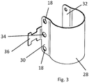
- FIG 3 shows the structure of the securement device 10.
- the securement device 10 includes a central portion 28 and two arms 30, 32. As shown in Figures 1A and 1B , in the assembled state the securement device 10 extends around the header 2 of the microchannel heat exchanger 1. The central portion 28 therefore has a curved profile to correspond to the curved profile of the header 2.
- the securement device 10 includes at least one first hole 34 into which the temperature sensor 6 extends in the assembled state (see Figure 1B ).
- the temperature sensor 6 may extend through one or both arms 30, 32 of the securement device 10. Therefore one or both of the arms 30, 32 may include the first hole 34 for receiving the temperature sensor 6.
- the securement device 10 also includes second holes 18 for receiving the fasteners 16.
- a projection feature 36 may extend outwardly from the securement device 10. In the assembled state the second end 22 of the temperature sensor 6 may extend along the projection feature 36.
- the projection feature 36 may provide support to the temperature sensor 6 in the assembled state to prevent damage to the sensor 6.
- the projection feature 36 may enable the temperature sensor 6 to be easily fastened to the securement device 10.
- a cable tie (not shown) may extend around the second end 22 of the temperature sensor 6 and the projection feature 36. This advantageously reduces the risk of the temperature sensor 6 being pulled out of the support block 8, such as during operation or transportation of the microchannel heat exchanger.
- the temperature sensor 6 is therefore held securely in a predetermined position relative to the fin package 4. It is therefore possible to obtain consistent temperature readings of the fin package 4.
Landscapes
- Physics & Mathematics (AREA)
- Engineering & Computer Science (AREA)
- General Physics & Mathematics (AREA)
- Mechanical Engineering (AREA)
- Thermal Sciences (AREA)
- General Engineering & Computer Science (AREA)
- Heat-Exchange Devices With Radiators And Conduit Assemblies (AREA)
Abstract
Description
- The present invention relates to microchannel heat exchangers, and specifically to fixation of a temperature sensor within a fin package of a microchannel heat exchanger.
- Heat exchangers often include sensors for monitoring various aspects or parameters of the heat exchanger. Examples of typical parameters which are monitored include temperature and pressure. Some systems use the measurements from sensors in a heat exchanger to control aspects or components of a refrigeration system, e.g. activation or speed of a fan can be controlled based on temperature measurements. Location of the sensor within the heat exchanger will depend on the specific parameter being measured and the component being controlled based on the sensor measurements. Some sensors are located on the surface of the heat exchanger. Other sensors can be located within the heat exchanger, such as within the fin package. In the case of microchannel heat exchangers, sensors are used for control purposes such as air temperature control, surface temperature control and defrost termination control. To achieve optimal control the sensor must be able to accurately measure the parameter being monitored. Therefore optimal location and installation of sensors is important.
- Previously, microchannel heat exchangers were predominantly used as condensers in refrigeration circuits. Condensers are not generally used for control purposes and so they do not usually include sensors, such as temperature sensors, to monitor parameters within the condenser. As such there has been no need for a standard mechanism for placement or fixation of temperature sensors in microchannel heat exchangers. Recently there has been an increased use of microchannel heat exchangers as evaporators in refrigeration circuits. Evaporators often use temperature sensors for control purposes, such as for control systems described above, and thus there is a new need for a mechanism for placement of a temperature sensor in a microchannel heat exchanger.
- It can be difficult to use sensor measurements to control aspects of a refrigeration system when there is high variation of the parameter being measured by the sensor, for example high temperature variation. Temperature variation can be influenced by various factors such as location of the temperature sensor, and amount or stability of thermal contact between the temperature sensor and the component being monitored. It is particularly important to minimise temperature variation when a temperature sensor in a microchannel heat exchanger is used for control purposes. Optimal placement of the sensor is therefore of high importance in these systems.
- In some conventional heat exchangers the sensor placement is uncontrolled and/or unspecified. For example there may be no standard location for fixing the temperature sensor to the heat exchanger and so the person installing the sensor has to arbitrarily decide on the placement of the sensor. This can lead to variation in the placement of the sensor among different heat exchangers which can cause temperature measurements to be inconsistent. Additionally the person installing the sensor may not position the sensor in the optimal location for achieving accurate and consistent measurements.
- Some conventional heat exchangers provide a fixed location for a temperature sensor or a fixed housing into which the sensor can be placed. However it is often required for the temperature sensor or the sensor housing to be positioned in the heat exchanger during manufacture of the heat exchanger so that the heat exchanger can form around the sensor or housing. Such sensors or sensor housings thus form an integral part of the heat exchanger so cannot be easily removed or replaced. Furthermore some conventional heat exchangers require components of the heat exchanger to be physically deformed to enable placement and/or fixation of the sensor. This makes it very difficult or impossible for existing heat exchangers to be retrofitted with temperature sensors.
- Viewed from a first aspect, the present invention provides a microchannel heat exchanger comprising: a plurality of fins and a plurality of microchannel tubes arranged in a fin package; a temperature sensor arranged to detect a temperature of the fin package; a support block disposed between adjacent microchannel tubes in a predetermined position relative to the fin package and comprising an opening arranged to house a thermosensitive element of the temperature sensor, the support block being configured to provide thermal contact between the fin package and the thermosensitive element of the temperature sensor; and a securement device fastened to the fin package, wherein the securement device is configured to secure the thermosensitive element of the temperature sensor in the support block.
- The support assembly of the microchannel heat exchanger enables the temperature sensor to be securely positioned within the fin package and consistently placed in the predetermined position so that variation of temperature measurement between different heat exchangers is minimised. The heat exchanger and the support assembly may be mass manufactured and it is important to ensure a consistent placement of the sensor in order that the measured temperature of the fin package has a consistent relationship with the operating conditions of the heat exchanger, i.e. internal temperatures and the temperature of a fluid (such as a refrigerant) within the heat exchanger. The predetermined position may place the thermosensitive element of the temperature sensor between a predetermined pair of adjacent microchannel tubes and/or at a certain distance from edges or outer surfaces of the heat exchanger. The support assembly provides a stable and robust mechanism for fixing the temperature sensor to prevent movement of the sensor, as well as ensuring consistent placement of the sensor so that consistent measurements are achieved.
- The heat exchanger may be heat absorbing heat exchanger, such as a microchannel evaporator for a refrigeration system. It can be of particular benefit to obtain an accurate and reliable temperature measurement in that context, such as for determining an inlet or outlet temperature of the heat absorbing heat exchanger to thereby enable accurate control of superheat or other parameters of a refrigeration system.
- The fin package comprises a plurality of fins and a plurality of microchannel tubes. The fins and microchannel tubes may be brazed together. Refrigerant can flow through the microchannel tubes during use of the heat exchanger. The microchannel tubes may be microchannel flat tubes. The fins increase the contact area of air in the fin package to increase the heat transfer in the heat exchanger. The temperature sensor is a sensor capable of measuring the temperature of the fin package and this would typically be done in order to determine the properties (i.e. temperature and/or changes in temperature) of the fluid within the fin package. Thus, an exterior temperature of the fin package may be used to infer information about the internal temperature, including changes to temperature and/or the rate of change. The temperature sensor may be arranged to measure the temperature of one or more fins of the fin package, such as by determining a temperature of the support block when it is in thermal contact with adjacent fins. The temperature sensor may be arranged to measure the temperature of one or more of the microchannel tubes, such as by determining a temperature of the support block when it is in thermal contact with adjacent microchannel tubes, and thus obtain information about the temperature of the refrigerant flowing within the tube. The measured temperature may be a temperature between the temperature of the microchannel tubes and the temperature of the fins. The temperature sensor may be a temperature probe. The sensor may have a substantially cylindrical shape. The temperature sensor may have a first end which extends into the fin package and a second end which is external to the fin package. The first end may be a thermosensitive end to measure the temperature of the fin package and thus may comprise the thermosensitive element. The thermosensitive element is an element that is sensitive to heat and fluctuations in temperature, such as an element having electrical properties (resistance, for example) that vary as the temperature varies. The first end may be housed within the opening of the support block of the support assembly. The second end may be a cable which may couple the thermosensitive end of the temperature sensor to a controller. The controller may control an aspect of a refrigeration system based on the measurements from the temperature sensor.
- The support block is disposed between adjacent microchannel tubes of the fin package and has an opening configured to house the thermosensitive element of the temperature sensor. The support block may be termed a sensor case. The support block is advantageously arranged to make thermal contact with the adjacent microchannel tubes as well as with the thermosensitive element of the temperature sensor, such as by having a friction fit with the microchannel tubes and/or with the thermosensitive element. The support block may be brazed to the microchannel tubes, which may occur in the same step of the manufacturing process in which the microchannel tubes are brazed to the fins. Many configurations of support block are possible as long as they ensure good thermal contact between the temperature sensor and the fin package and ensure secure fixation of the temperature sensor within the fin package. For example the opening of the support block may include a bore extending partially or completely through the support block and the temperature sensor may be arranged inside the bore. The support block may include alignment formations for locating the temperature sensor in the predetermined position. For example, the bore may include alignment formations for guiding insertion of the temperature sensor to a required distance within the support block, to thereby place it at a required location relative to the extent of the fin package.
- The support block may comprise two or more sections. This may allow ease of installation of the temperature sensing assembly. In one example the support block comprises a first section for insertion into the fin package from a first side of the heat exchanger, and a second section for insertion into the fin package from a second side of the heat exchanger. In this way the support block can be closely fitted from both sides, hence giving a good thermal contact, even when the shape of the fins or the microchannel tubes would not permit insertion of a single piece with the same close fit, such as when the gap between fins or microchannel tubes narrows toward a central part thereof.
- The support block conveys thermal energy from the fin package to the temperature sensor. The support block may therefore be designed to optimise heat transfer to ensure accurate temperature readings by the temperature sensor. For example, the support block may comprise a good thermally conductive material such as a metal material. The microchannel heat exchanger typically comprises aluminium. The support block and/or other components of the sensor assembly may therefore comprise aluminium to reduce corrosion between components. The part of the temperature sensor which is housed in the support block may have an outer contour which matches an inner contour of the support block to maintain good thermal contact between the temperature sensor and the support block. The inner contour of the support block may be arranged to ensure a required positioning of the temperature sensor within the support block, and hence may provide an alignment formation as discussed above. An outer contour of the support block may be shaped to match the location of the support block within the fin package, and thus may match an outer contour of the adjacent microchannel tubes.
- The securement device is fastened to the heat exchanger and may be disposed external to the fin package. The securement device may be fastened by a fastening mechanism such as a screw. The screw may comprise steel, such as non-corrosive steel. The securement device may be configured to enable the temperature sensor to extend therethrough. For example the securement device may comprise a hole which is sized to receive a part of the temperature sensor. To ensure a secure placement of the temperature sensor, an inner profile of the hole of the securement device may equal the outer profile of the temperature sensor. The profiles may closely match in such a way that the temperature sensor is able to be inserted into the hole during assembly but will still remain securely positioned after assembly. The securement device may hence avoid or prevent movement of the support block and/or of the temperature sensor once the support assembly has been assembled. The securement device may have a variety of configurations. An exemplary securement device is a bracket or a clip that may fit around a header of the microchannel heat exchanger. The clip may comprise a central portion and two arms. Each arm may extend on either side of the fin package, such as by extending around the header of the microchannel heat exchanger. Each arm of the clip may include a hole into which the temperature sensor can extend. The position of the hole(s) may enable the temperature sensor to be consistently located in a predetermined position relative to the position of the securement device. For example, if the securement device extends around a header then the securement device will ensure the temperature sensor is positioned a predetermined distance from the header.
- The temperature sensor may extend through the support block and the securement device. Since the securement device is fixed to the heat exchanger, the assembly therefore causes the temperature sensor and the support block to be fixed relative to the heat exchanger. There may be an additional fastening mechanism to fasten the temperature sensor to the securement device, such as a cable tie. This may ensure that each component of the temperature sensing assembly is fixed relative to each other and relative to the heat exchanger. When assembled, the support assembly therefore provides a stable and robust fixation of the temperature sensor in the microchannel heat exchanger, while also ensuring good thermal contact between the temperature sensor and the fin package. The temperature sensor may be able to be removed easily from the support block when desired, such as by a technician for replacement in the case of failure of the sensor. It is therefore beneficial that the sensor is secured in the support block by the securement device so it does not become displaced when it is not desired to remove the sensor, e.g. during operation or transportation of the microchannel heat exchanger.
- The temperature sensing assembly may be positioned near an end of the fin package. For instance the temperature assembly may be located close to a header of the microchannel heat exchanger, which may be the inlet header or the outlet header for a heat absorbing heat exchanger, such as an evaporator. It has been found that a temperature measured at the microchannel heat exchanger inlet is the most similar in value to the evaporation temperature, and thus a position between the inlet header and the fin package is an optimal sensor position for recording an accurate evaporation temperature. It can be of significance to determine the inlet temperature, such as in the context of assessing evaporator inlet conditions for a refrigeration circuit incorporating the heat exchanger as a heat absorbing heat exchanger. It can also be of significance to determine the outlet temperature, such as in the context of observing evaporator superheating. In this case the sensor may be positioned near the outlet header. The securement device may fix the temperature sensor and the support block to the header. For example, when the securement device is a bracket or a clip, the central portion may extend around the external surface of the header and each arm may extend along either side of the fin package.
- As discussed previously, the concept of temperature sensor fixation when a microchannel heat exchanger is acting as an evaporator rather than a condenser is also considered to be new. The invention therefore provides a refrigeration circuit comprising an evaporator, wherein the evaporator includes the microchannel heat exchanger of the first aspect of the invention.
- One exemplary use of such a refrigeration circuit is to refrigerate a compartment in a refrigerated display cabinet. Refrigerated compartments can be used to store and/or display perishable goods at particular conditions according to the requirements of the perishable goods which are being stored/displayed. Therefore the invention also provides a refrigerated display cabinet comprising: a refrigeration circuit comprising an evaporator, wherein the evaporator includes the microchannel heat exchanger of the first aspect of the invention, and a compartment to be refrigerated.
- The microchannel heat exchanger may be operated such that the temperature sensor is above zero degrees Celsius. As discussed above, the present system advantageously ensures that the reading from the temperature sensor is similar to the evaporation temperature. The cabinet can therefore be operated without regular defrost periods. It is desirable to operate the refrigeration cabinet without regular defrost periods because then there is no need for defrost heaters, which leads to energy savings and cost savings. A refrigerated cabinet with a microchannel heat exchanger operating in this way may be termed a frost-free cabinet due to the prevention of the accumulation of frost in the system.
- From a further aspect, there is provided a method of assembling a microchannel heat exchanger comprising: arranging a plurality of fins and a plurality of microchannel tubes to form a fin package; inserting a support block in a predetermined position between adjacent microchannel tubes of the fin package; securing the support block in the predetermined position; inserting a temperature sensor through a securement device and into an opening of the support block; and fastening the securement device to the fin package such that the securement device secures the position of the temperature sensor in the support block.
- The method may comprise inserting a first section of the support block into the fin package from a first side of the heat exchanger, and inserting a second section of the support block into the fin package from a second side of the heat exchanger. The method may comprise arranging the securement device around a header of the microchannel heat exchanger, which may be an inlet header. The method may comprise fastening the temperature sensor to the securement device.
- The microchannel heat exchanger may be the microchannel heat exchanger according to the first aspect. The microchannel heat exchanger may comprise any of the features described above.
- Certain embodiments will now be described by way of example only and with reference to the accompanying drawings, in which:
-
Figure 1A illustrates a microchannel heat exchanger with a temperature sensor fixation mechanism in a disassembled state; -
Figure 1B shows the microchannel heat exchanger ofFigure 1A in an assembled state; -
Figure 2A illustrates a temperature sensor and a support block of the temperature sensor fixation mechanism in a disassembled state; -
Figure 2B shows the temperature sensor and the support block ofFigure 2A in an assembled state; and -
Figure 3 illustrates a securement device of the temperature sensor fixation mechanism. -
Figures 1A and 1B show amicrochannel heat exchanger 1 comprising aheader 2 and a plurality of fins and a plurality of microchannel tubes arranged in afin package 4. The fins increase the contact area of air in the fin package to increase the heat transfer in the heat exchanger. The microchannel tubes, which can be microchannel flat tubes, allow refrigerant to flow therethrough.Figures 1A and 1B show components used to fix atemperature sensor 6 in thefin package 4 in a predetermined position so that thetemperature sensor 6 can detect a temperature of thefin package 4 with consistency. InFigure 1A the components are shown in a disassembled state so that all the components can be seen. InFigure 1B the components are arranged in an assembled state. - The components used to secure the
temperature sensor 6 in thefin package 4 include asupport block securement device 10. - In the assembled state the
support block 8 is disposed between adjacent microchannel tubes of thefin package 4. As shown inFigure 1A , thesupport block 8 comprises afirst section 8a and asecond section 8b. During installation of thesupport block 8 in thefin package 4, thefirst section 8a of thesupport block 8 may be inserted into thefin package 4 from afirst side 12 of theheat exchanger 1 and thesecond section 8b of thesupport block 8 may be inserted into thefin package 4 from asecond side 14 of theheat exchanger 1. Thesupport block 8 includes an opening in which thetemperature sensor 6 is housed. This can be seen more clearly inFigure 2A which will be described in more detail below. - The
support block 8 is configured to provide thermal contact between thefin package 4 and a thermosensitive element of thetemperature sensor 6. Thesupport block 8 has an outer contour which is shaped to match the location of thesupport block 8 within thefin package 4. In the assembled state thesupport block 8 abuts theheader 2. Thus the surface of thesupport block 8 that contacts theheader 2 has a contour which matches the contour of theheader 2. Other surfaces of thesupport block 8 have contours which match the contours of the microchannel tubes between which thesupport block 8 is disposed. Thesupport block 8 is arranged between the adjacent microchannel tubes by a friction fit or by being brazed. - The
securement device 10 is configured to secure thetemperature sensor 6 in a predetermined position relative to thefin package 4. The structure of thesecurement device 10 can be seen more clearly inFigure 3 , which is described below. In this example thesecurement device 10 is a clip which extends around theheader 2 of themicrochannel heat exchanger 1. Thesecurement device 10 includes two arms. The first arm extends along thefirst side 12 of thefin package 4 and the second arm extends along thesecond side 14 of thefin package 4. Thesecurement device 10 is fastened to thefin package 4 withfasteners 16. Thefasteners 16 are screws in this example, but it will be appreciated that any suitable fasteners can be used. Thefasteners 16 extend throughholes 18 in thesecurement device 10 and extend into thefin package 4. This ensures that thesecurement device 10 is fixed relative to thefin package 4. - In the assembled state, the temperature sensor 6 (which can be seen in
Figure 1B ) extends through thesecurement device 10 and into the opening of thesupport block 8. Thetemperature sensor 6 comprises afirst end 20 which is housed in the opening of thesupport block 8 and asecond end 22 which is external to thefin package 4. These are shown more clearly inFigure 2A . Thefirst end 20 comprises the thermosensitive element so that the temperature of thefin package 4 can be detected. Thesecond end 22 is a cable which extends between thefirst end 20 and a switchbox (not shown). The switchbox may include a controller. Thesecond end 22 may be fastened to thesecurement device 10. -
Figure 2A shows thetemperature sensor 6 and thesupport block 8 in a disassembled state andFigure 2B shows thetemperature sensor 6 and thesupport block 8 in an assembled state. - As shown in
Figure 2A , thetemperature sensor 6 comprises afirst end 20 and asecond end 22. Thetemperature sensor 6 has a substantially cylindrical shape. Thesupport block 8 comprises thefirst section 8a and thesecond section 8b which are in contact in the assembled state. As explained previously, this can allow for ease of installation of thesupport block 8. Thesupport block 8 includes anopening 24, which is abore 24 in this example. Thebore 24 extends through thefirst section 8a and thesecond section 8b of thesupport block 8. In the assembled state thefirst end 20 of thetemperature sensor 6 is housed in thebore 24. The outer surface of thetemperature sensor 6 and the surface of thebore 24 have corresponding profiles and sizes. This ensures good thermal contact between thetemperature sensor 6 and thesupport block 8 and prevents movement of thetemperature sensor 6 within thesupport block 8. Thetemperature sensor 6 is arranged in thesupport block 8 by a friction fit. - Although not shown in the Figures, the
support block 8 may include an alignment formation. The alignment formation may guide insertion of thetemperature sensor 6 to a required distance within thesupport block 8, to thereby place it at a required location relative to the extent of thefin package 4. - As shown in
Figure 2B , thesupport block 8 includes acurved surface 26. Thecurved surface 26 is shaped to correspond to a curved surface of theheader 2. Thesupport block 8 may therefore be positioned securely against theheader 2, and good thermal contact between thesupport block 8 and theheader 2 may be maintained. -
Figure 3 shows the structure of thesecurement device 10. Thesecurement device 10 includes acentral portion 28 and twoarms Figures 1A and 1B , in the assembled state thesecurement device 10 extends around theheader 2 of themicrochannel heat exchanger 1. Thecentral portion 28 therefore has a curved profile to correspond to the curved profile of theheader 2. - The
securement device 10 includes at least onefirst hole 34 into which thetemperature sensor 6 extends in the assembled state (seeFigure 1B ). Thetemperature sensor 6 may extend through one or botharms securement device 10. Therefore one or both of thearms first hole 34 for receiving thetemperature sensor 6. Thesecurement device 10 also includessecond holes 18 for receiving thefasteners 16. Aprojection feature 36 may extend outwardly from thesecurement device 10. In the assembled state thesecond end 22 of thetemperature sensor 6 may extend along theprojection feature 36. Theprojection feature 36 may provide support to thetemperature sensor 6 in the assembled state to prevent damage to thesensor 6. Theprojection feature 36 may enable thetemperature sensor 6 to be easily fastened to thesecurement device 10. For example a cable tie (not shown) may extend around thesecond end 22 of thetemperature sensor 6 and theprojection feature 36. This advantageously reduces the risk of thetemperature sensor 6 being pulled out of thesupport block 8, such as during operation or transportation of the microchannel heat exchanger. - In the assembled state, the
temperature sensor 6 is therefore held securely in a predetermined position relative to thefin package 4. It is therefore possible to obtain consistent temperature readings of thefin package 4.
Claims (15)
- A microchannel heat exchanger comprising:a plurality of fins and a plurality of microchannel tubes arranged in a fin package;a temperature sensor arranged to detect a temperature of the fin package;a support block disposed between adjacent microchannel tubes in a predetermined position relative to the fin package and comprising an opening arranged to house a thermosensitive element of the temperature sensor, the support block being configured to provide thermal contact between the fin package and the thermosensitive element of the temperature sensor; anda securement device fastened to the fin package, wherein the securement device is configured to secure the thermosensitive element of the temperature sensor in the support block.
- A microchannel heat exchanger as claimed in claim 1, wherein the temperature sensor extends through the securement device and into the opening of the support block.
- A microchannel heat exchanger as claimed in claim 1 or 2, wherein the securement device is located external to the fin package.
- A microchannel heat exchanger as claimed in claim 1, 2 or 3, wherein the predetermined position places the thermosensitive element of the temperature sensor between a predetermined pair of adjacent microchannel tubes and/or at a predetermined distance from an edge or outer surface of the heat exchanger.
- A microchannel heat exchanger as claimed in any preceding claim, wherein the support block is arranged to make thermal contact with the adjacent microchannel tubes by having a friction fit with the microchannel tubes or by being brazed to the microchannel tubes.
- A microchannel heat exchanger as claimed in any preceding claim, wherein the support block is arranged to make thermal contact with the thermosensitive element of the temperature sensor by having a friction fit with the thermosensitive element.
- A microchannel heat exchanger as claimed in any preceding claim, wherein the opening of the support block includes a bore through the support block and wherein the thermosensitive element of the temperature sensor extends into the bore.
- A microchannel heat exchanger as claimed in any preceding claim, wherein the support block includes an alignment formation for locating the temperature sensor in the predetermined position.
- A microchannel heat exchanger as claimed in any preceding claim, wherein the support block comprises a first section for insertion into the fin package from a first side of the heat exchanger and a second section for insertion into the fin package from a second side of the heat exchanger.
- A microchannel heat exchanger as claimed in any preceding claim, wherein the temperature sensor is fastened to the securement device.
- A microchannel heat exchanger as claimed in any preceding claim, wherein the securement device is a bracket or a clip.
- A microchannel heat exchanger as claimed in any preceding claim, wherein the temperature sensor, the support block and the securement device are located near a header of the microchannel heat exchanger, wherein the header is optionally an inlet header.
- A refrigeration circuit comprising an evaporator, wherein the evaporator is the microchannel heat exchanger of any preceding claim.
- A refrigerated display cabinet comprising the refrigeration circuit of claim 13 and a compartment to be refrigerated.
- A method of assembling a microchannel heat exchanger comprising:arranging a plurality of fins and a plurality of microchannel tubes to form a fin package;inserting a support block in a predetermined position between adjacent microchannel tubes of the fin package;securing the support block in the predetermined position;inserting a temperature sensor through a securement device and into an opening of the support block; andfastening the securement device to the fin package such that the securement device secures the position of the temperature sensor in the support block;wherein the method optionally comprises providing the microchannel heat exchanger with features as claimed in any of claims 1 to 12.
Priority Applications (2)
| Application Number | Priority Date | Filing Date | Title |
|---|---|---|---|
| EP20156239.4A EP3862714B1 (en) | 2020-02-07 | 2020-02-07 | Temperature sensor fixation on microchannel heat exchanger |
| CN202011501135.8A CN113251705A (en) | 2020-02-07 | 2020-12-18 | Temperature sensor mounting on microchannel heat exchanger |
Applications Claiming Priority (1)
| Application Number | Priority Date | Filing Date | Title |
|---|---|---|---|
| EP20156239.4A EP3862714B1 (en) | 2020-02-07 | 2020-02-07 | Temperature sensor fixation on microchannel heat exchanger |
Publications (2)
| Publication Number | Publication Date |
|---|---|
| EP3862714A1 true EP3862714A1 (en) | 2021-08-11 |
| EP3862714B1 EP3862714B1 (en) | 2022-08-17 |
Family
ID=69528647
Family Applications (1)
| Application Number | Title | Priority Date | Filing Date |
|---|---|---|---|
| EP20156239.4A Active EP3862714B1 (en) | 2020-02-07 | 2020-02-07 | Temperature sensor fixation on microchannel heat exchanger |
Country Status (2)
| Country | Link |
|---|---|
| EP (1) | EP3862714B1 (en) |
| CN (1) | CN113251705A (en) |
Cited By (1)
| Publication number | Priority date | Publication date | Assignee | Title |
|---|---|---|---|---|
| CN116379646A (en) * | 2023-04-13 | 2023-07-04 | 广东华天成新能源科技股份有限公司 | Air source heat pump with accurate temperature measurement |
Families Citing this family (1)
| Publication number | Priority date | Publication date | Assignee | Title |
|---|---|---|---|---|
| WO2026012889A1 (en) * | 2024-07-12 | 2026-01-15 | Danfoss A/S | Heated sensor arrangement |
Citations (6)
| Publication number | Priority date | Publication date | Assignee | Title |
|---|---|---|---|---|
| WO1999067610A1 (en) * | 1998-06-22 | 1999-12-29 | Springer Carrier S.A. | Sensor mounting clip |
| KR20040007975A (en) * | 2002-07-15 | 2004-01-28 | 삼성전자주식회사 | Temperature Sensor Fixing Holder |
| KR20050024881A (en) * | 2003-09-05 | 2005-03-11 | 엘지전자 주식회사 | Holder for temperature sensor of heat exchanger |
| US20120255703A1 (en) * | 2009-10-19 | 2012-10-11 | Sharp Kabushiki Kaisha | Heat exchanger and air conditioner incorporating same |
| JP2013217594A (en) * | 2012-04-10 | 2013-10-24 | Daikin Industries Ltd | Fixing structure of temperature transducer |
| US20160153839A1 (en) * | 2014-12-02 | 2016-06-02 | Lg Electronics Inc. | Temperature sensing apparatus for heat exchanger |
Family Cites Families (4)
| Publication number | Priority date | Publication date | Assignee | Title |
|---|---|---|---|---|
| JP5987455B2 (en) * | 2012-04-27 | 2016-09-07 | ダイキン工業株式会社 | Heat exchanger |
| CN204268778U (en) * | 2014-11-13 | 2015-04-15 | 青岛海容商用冷链股份有限公司 | Use the freezing display case unit of micro-channel condenser |
| WO2016185658A1 (en) * | 2015-05-18 | 2016-11-24 | 株式会社デンソー | Heat exchanger unit |
| JP6056928B1 (en) * | 2015-09-09 | 2017-01-11 | 株式会社富士通ゼネラル | Microchannel heat exchanger |
-
2020
- 2020-02-07 EP EP20156239.4A patent/EP3862714B1/en active Active
- 2020-12-18 CN CN202011501135.8A patent/CN113251705A/en active Pending
Patent Citations (6)
| Publication number | Priority date | Publication date | Assignee | Title |
|---|---|---|---|---|
| WO1999067610A1 (en) * | 1998-06-22 | 1999-12-29 | Springer Carrier S.A. | Sensor mounting clip |
| KR20040007975A (en) * | 2002-07-15 | 2004-01-28 | 삼성전자주식회사 | Temperature Sensor Fixing Holder |
| KR20050024881A (en) * | 2003-09-05 | 2005-03-11 | 엘지전자 주식회사 | Holder for temperature sensor of heat exchanger |
| US20120255703A1 (en) * | 2009-10-19 | 2012-10-11 | Sharp Kabushiki Kaisha | Heat exchanger and air conditioner incorporating same |
| JP2013217594A (en) * | 2012-04-10 | 2013-10-24 | Daikin Industries Ltd | Fixing structure of temperature transducer |
| US20160153839A1 (en) * | 2014-12-02 | 2016-06-02 | Lg Electronics Inc. | Temperature sensing apparatus for heat exchanger |
Cited By (2)
| Publication number | Priority date | Publication date | Assignee | Title |
|---|---|---|---|---|
| CN116379646A (en) * | 2023-04-13 | 2023-07-04 | 广东华天成新能源科技股份有限公司 | Air source heat pump with accurate temperature measurement |
| CN116379646B (en) * | 2023-04-13 | 2024-03-22 | 广东华天成新能源科技股份有限公司 | Air source heat pump with accurate temperature measurement |
Also Published As
| Publication number | Publication date |
|---|---|
| CN113251705A (en) | 2021-08-13 |
| EP3862714B1 (en) | 2022-08-17 |
Similar Documents
| Publication | Publication Date | Title |
|---|---|---|
| US8100167B2 (en) | Method and a device for detecting an abnormality of a heat exchanger, and the use of such a device | |
| US6467282B1 (en) | Frost sensor for use in defrost controls for refrigeration | |
| EP3862714B1 (en) | Temperature sensor fixation on microchannel heat exchanger | |
| JP6021954B2 (en) | Liquid level detection device and refrigeration air conditioner | |
| CN203404869U (en) | Temperature measurement assembly used for air conditioner outdoor unit and air conditioner outdoor unit provided with temperature measurement assembly | |
| US20160153839A1 (en) | Temperature sensing apparatus for heat exchanger | |
| US5763774A (en) | Fluid flow meter with reduced orientation sensitivity | |
| JP5474025B2 (en) | Liquid level detection device and refrigeration air conditioner provided with the same | |
| US5691466A (en) | Liquid-sensing apparatus and method | |
| JP5822900B2 (en) | Liquid level detection device and refrigeration air conditioner provided with the same | |
| US4385658A (en) | Fluid temperature measuring device | |
| CN107421084B (en) | Temperature sensing bulb support for air conditioner indoor unit and air conditioner indoor unit | |
| CN207162875U (en) | Temperature-sensitive bag support and indoor apparatus of air conditioner for indoor apparatus of air conditioner | |
| EP3620729B1 (en) | Thermal monitoring for cooling systems | |
| CN224230414U (en) | Refrigerating apparatus | |
| CN207501520U (en) | A kind of refrigerator | |
| EP3578901B1 (en) | Temperature-sensing package support used for air-conditioner indoor unit, and air-conditioner indoor unit | |
| CN113899152A (en) | Refrigerating unit, defrosting control method thereof and refrigeration house | |
| CN222336560U (en) | Mounting bracket for temperature sensor and refrigeration equipment | |
| KR100381656B1 (en) | Structure for installing a thermo sensor for use in a Kimchi storage apparatus | |
| JP2010210211A (en) | Refrigerating device | |
| CN216522074U (en) | Outdoor machine of air conditioner | |
| US12618605B2 (en) | Refrigeration system with demand fluid defrost | |
| CN204555436U (en) | For refrigeration plant evaporator assemblies and there is its refrigerator | |
| KR200422097Y1 (en) | Temperature Sensing Structure of Automotive Evaporator |
Legal Events
| Date | Code | Title | Description |
|---|---|---|---|
| PUAI | Public reference made under article 153(3) epc to a published international application that has entered the european phase |
Free format text: ORIGINAL CODE: 0009012 |
|
| STAA | Information on the status of an ep patent application or granted ep patent |
Free format text: STATUS: THE APPLICATION HAS BEEN PUBLISHED |
|
| AK | Designated contracting states |
Kind code of ref document: A1 Designated state(s): AL AT BE BG CH CY CZ DE DK EE ES FI FR GB GR HR HU IE IS IT LI LT LU LV MC MK MT NL NO PL PT RO RS SE SI SK SM TR |
|
| STAA | Information on the status of an ep patent application or granted ep patent |
Free format text: STATUS: REQUEST FOR EXAMINATION WAS MADE |
|
| GRAP | Despatch of communication of intention to grant a patent |
Free format text: ORIGINAL CODE: EPIDOSNIGR1 |
|
| STAA | Information on the status of an ep patent application or granted ep patent |
Free format text: STATUS: GRANT OF PATENT IS INTENDED |
|
| 17P | Request for examination filed |
Effective date: 20220209 |
|
| RBV | Designated contracting states (corrected) |
Designated state(s): AL AT BE BG CH CY CZ DE DK EE ES FI FR GB GR HR HU IE IS IT LI LT LU LV MC MK MT NL NO PL PT RO RS SE SI SK SM TR |
|
| INTG | Intention to grant announced |
Effective date: 20220224 |
|
| RIC1 | Information provided on ipc code assigned before grant |
Ipc: G01K 1/16 20060101ALI20220211BHEP Ipc: G01K 13/02 20210101ALI20220211BHEP Ipc: G01K 1/143 20210101ALI20220211BHEP Ipc: F28F 27/00 20060101ALI20220211BHEP Ipc: F28F 9/02 20060101AFI20220211BHEP |
|
| GRAS | Grant fee paid |
Free format text: ORIGINAL CODE: EPIDOSNIGR3 |
|
| GRAA | (expected) grant |
Free format text: ORIGINAL CODE: 0009210 |
|
| STAA | Information on the status of an ep patent application or granted ep patent |
Free format text: STATUS: THE PATENT HAS BEEN GRANTED |
|
| AK | Designated contracting states |
Kind code of ref document: B1 Designated state(s): AL AT BE BG CH CY CZ DE DK EE ES FI FR GB GR HR HU IE IS IT LI LT LU LV MC MK MT NL NO PL PT RO RS SE SI SK SM TR |
|
| REG | Reference to a national code |
Ref country code: CH Ref legal event code: EP |
|
| REG | Reference to a national code |
Ref country code: DE Ref legal event code: R096 Ref document number: 602020004506 Country of ref document: DE |
|
| REG | Reference to a national code |
Ref country code: IE Ref legal event code: FG4D |
|
| REG | Reference to a national code |
Ref country code: AT Ref legal event code: REF Ref document number: 1512446 Country of ref document: AT Kind code of ref document: T Effective date: 20220915 |
|
| REG | Reference to a national code |
Ref country code: NL Ref legal event code: FP |
|
| REG | Reference to a national code |
Ref country code: LT Ref legal event code: MG9D |
|
| PG25 | Lapsed in a contracting state [announced via postgrant information from national office to epo] |
Ref country code: SE Free format text: LAPSE BECAUSE OF FAILURE TO SUBMIT A TRANSLATION OF THE DESCRIPTION OR TO PAY THE FEE WITHIN THE PRESCRIBED TIME-LIMIT Effective date: 20220817 Ref country code: RS Free format text: LAPSE BECAUSE OF FAILURE TO SUBMIT A TRANSLATION OF THE DESCRIPTION OR TO PAY THE FEE WITHIN THE PRESCRIBED TIME-LIMIT Effective date: 20220817 Ref country code: PT Free format text: LAPSE BECAUSE OF FAILURE TO SUBMIT A TRANSLATION OF THE DESCRIPTION OR TO PAY THE FEE WITHIN THE PRESCRIBED TIME-LIMIT Effective date: 20221219 Ref country code: NO Free format text: LAPSE BECAUSE OF FAILURE TO SUBMIT A TRANSLATION OF THE DESCRIPTION OR TO PAY THE FEE WITHIN THE PRESCRIBED TIME-LIMIT Effective date: 20221117 Ref country code: LV Free format text: LAPSE BECAUSE OF FAILURE TO SUBMIT A TRANSLATION OF THE DESCRIPTION OR TO PAY THE FEE WITHIN THE PRESCRIBED TIME-LIMIT Effective date: 20220817 Ref country code: LT Free format text: LAPSE BECAUSE OF FAILURE TO SUBMIT A TRANSLATION OF THE DESCRIPTION OR TO PAY THE FEE WITHIN THE PRESCRIBED TIME-LIMIT Effective date: 20220817 Ref country code: FI Free format text: LAPSE BECAUSE OF FAILURE TO SUBMIT A TRANSLATION OF THE DESCRIPTION OR TO PAY THE FEE WITHIN THE PRESCRIBED TIME-LIMIT Effective date: 20220817 |
|
| REG | Reference to a national code |
Ref country code: AT Ref legal event code: MK05 Ref document number: 1512446 Country of ref document: AT Kind code of ref document: T Effective date: 20220817 |
|
| PG25 | Lapsed in a contracting state [announced via postgrant information from national office to epo] |
Ref country code: PL Free format text: LAPSE BECAUSE OF FAILURE TO SUBMIT A TRANSLATION OF THE DESCRIPTION OR TO PAY THE FEE WITHIN THE PRESCRIBED TIME-LIMIT Effective date: 20220817 Ref country code: IS Free format text: LAPSE BECAUSE OF FAILURE TO SUBMIT A TRANSLATION OF THE DESCRIPTION OR TO PAY THE FEE WITHIN THE PRESCRIBED TIME-LIMIT Effective date: 20221217 Ref country code: HR Free format text: LAPSE BECAUSE OF FAILURE TO SUBMIT A TRANSLATION OF THE DESCRIPTION OR TO PAY THE FEE WITHIN THE PRESCRIBED TIME-LIMIT Effective date: 20220817 Ref country code: GR Free format text: LAPSE BECAUSE OF FAILURE TO SUBMIT A TRANSLATION OF THE DESCRIPTION OR TO PAY THE FEE WITHIN THE PRESCRIBED TIME-LIMIT Effective date: 20221118 |
|
| PG25 | Lapsed in a contracting state [announced via postgrant information from national office to epo] |
Ref country code: SM Free format text: LAPSE BECAUSE OF FAILURE TO SUBMIT A TRANSLATION OF THE DESCRIPTION OR TO PAY THE FEE WITHIN THE PRESCRIBED TIME-LIMIT Effective date: 20220817 Ref country code: RO Free format text: LAPSE BECAUSE OF FAILURE TO SUBMIT A TRANSLATION OF THE DESCRIPTION OR TO PAY THE FEE WITHIN THE PRESCRIBED TIME-LIMIT Effective date: 20220817 Ref country code: ES Free format text: LAPSE BECAUSE OF FAILURE TO SUBMIT A TRANSLATION OF THE DESCRIPTION OR TO PAY THE FEE WITHIN THE PRESCRIBED TIME-LIMIT Effective date: 20220817 Ref country code: DK Free format text: LAPSE BECAUSE OF FAILURE TO SUBMIT A TRANSLATION OF THE DESCRIPTION OR TO PAY THE FEE WITHIN THE PRESCRIBED TIME-LIMIT Effective date: 20220817 Ref country code: CZ Free format text: LAPSE BECAUSE OF FAILURE TO SUBMIT A TRANSLATION OF THE DESCRIPTION OR TO PAY THE FEE WITHIN THE PRESCRIBED TIME-LIMIT Effective date: 20220817 Ref country code: AT Free format text: LAPSE BECAUSE OF FAILURE TO SUBMIT A TRANSLATION OF THE DESCRIPTION OR TO PAY THE FEE WITHIN THE PRESCRIBED TIME-LIMIT Effective date: 20220817 |
|
| REG | Reference to a national code |
Ref country code: DE Ref legal event code: R097 Ref document number: 602020004506 Country of ref document: DE |
|
| PG25 | Lapsed in a contracting state [announced via postgrant information from national office to epo] |
Ref country code: SK Free format text: LAPSE BECAUSE OF FAILURE TO SUBMIT A TRANSLATION OF THE DESCRIPTION OR TO PAY THE FEE WITHIN THE PRESCRIBED TIME-LIMIT Effective date: 20220817 Ref country code: EE Free format text: LAPSE BECAUSE OF FAILURE TO SUBMIT A TRANSLATION OF THE DESCRIPTION OR TO PAY THE FEE WITHIN THE PRESCRIBED TIME-LIMIT Effective date: 20220817 |
|
| PLBE | No opposition filed within time limit |
Free format text: ORIGINAL CODE: 0009261 |
|
| STAA | Information on the status of an ep patent application or granted ep patent |
Free format text: STATUS: NO OPPOSITION FILED WITHIN TIME LIMIT |
|
| PG25 | Lapsed in a contracting state [announced via postgrant information from national office to epo] |
Ref country code: AL Free format text: LAPSE BECAUSE OF FAILURE TO SUBMIT A TRANSLATION OF THE DESCRIPTION OR TO PAY THE FEE WITHIN THE PRESCRIBED TIME-LIMIT Effective date: 20220817 |
|
| 26N | No opposition filed |
Effective date: 20230519 |
|
| PG25 | Lapsed in a contracting state [announced via postgrant information from national office to epo] |
Ref country code: SI Free format text: LAPSE BECAUSE OF FAILURE TO SUBMIT A TRANSLATION OF THE DESCRIPTION OR TO PAY THE FEE WITHIN THE PRESCRIBED TIME-LIMIT Effective date: 20220817 |
|
| PG25 | Lapsed in a contracting state [announced via postgrant information from national office to epo] |
Ref country code: MC Free format text: LAPSE BECAUSE OF FAILURE TO SUBMIT A TRANSLATION OF THE DESCRIPTION OR TO PAY THE FEE WITHIN THE PRESCRIBED TIME-LIMIT Effective date: 20220817 |
|
| REG | Reference to a national code |
Ref country code: CH Ref legal event code: PL |
|
| REG | Reference to a national code |
Ref country code: BE Ref legal event code: MM Effective date: 20230228 |
|
| PG25 | Lapsed in a contracting state [announced via postgrant information from national office to epo] |
Ref country code: LU Free format text: LAPSE BECAUSE OF NON-PAYMENT OF DUE FEES Effective date: 20230207 Ref country code: LI Free format text: LAPSE BECAUSE OF NON-PAYMENT OF DUE FEES Effective date: 20230228 Ref country code: CH Free format text: LAPSE BECAUSE OF NON-PAYMENT OF DUE FEES Effective date: 20230228 |
|
| REG | Reference to a national code |
Ref country code: IE Ref legal event code: MM4A |
|
| PG25 | Lapsed in a contracting state [announced via postgrant information from national office to epo] |
Ref country code: IE Free format text: LAPSE BECAUSE OF NON-PAYMENT OF DUE FEES Effective date: 20230207 |
|
| P01 | Opt-out of the competence of the unified patent court (upc) registered |
Effective date: 20240119 |
|
| PG25 | Lapsed in a contracting state [announced via postgrant information from national office to epo] |
Ref country code: BE Free format text: LAPSE BECAUSE OF NON-PAYMENT OF DUE FEES Effective date: 20230228 |
|
| PGFP | Annual fee paid to national office [announced via postgrant information from national office to epo] |
Ref country code: NL Payment date: 20240123 Year of fee payment: 5 |
|
| PGFP | Annual fee paid to national office [announced via postgrant information from national office to epo] |
Ref country code: DE Payment date: 20240123 Year of fee payment: 5 Ref country code: GB Payment date: 20240123 Year of fee payment: 5 |
|
| PGFP | Annual fee paid to national office [announced via postgrant information from national office to epo] |
Ref country code: IT Payment date: 20240123 Year of fee payment: 5 Ref country code: FR Payment date: 20240123 Year of fee payment: 5 |
|
| PG25 | Lapsed in a contracting state [announced via postgrant information from national office to epo] |
Ref country code: BG Free format text: LAPSE BECAUSE OF FAILURE TO SUBMIT A TRANSLATION OF THE DESCRIPTION OR TO PAY THE FEE WITHIN THE PRESCRIBED TIME-LIMIT Effective date: 20220817 |
|
| PG25 | Lapsed in a contracting state [announced via postgrant information from national office to epo] |
Ref country code: BG Free format text: LAPSE BECAUSE OF FAILURE TO SUBMIT A TRANSLATION OF THE DESCRIPTION OR TO PAY THE FEE WITHIN THE PRESCRIBED TIME-LIMIT Effective date: 20220817 |
|
| PG25 | Lapsed in a contracting state [announced via postgrant information from national office to epo] |
Ref country code: CY Free format text: LAPSE BECAUSE OF FAILURE TO SUBMIT A TRANSLATION OF THE DESCRIPTION OR TO PAY THE FEE WITHIN THE PRESCRIBED TIME-LIMIT; INVALID AB INITIO Effective date: 20200207 |
|
| PG25 | Lapsed in a contracting state [announced via postgrant information from national office to epo] |
Ref country code: HU Free format text: LAPSE BECAUSE OF FAILURE TO SUBMIT A TRANSLATION OF THE DESCRIPTION OR TO PAY THE FEE WITHIN THE PRESCRIBED TIME-LIMIT; INVALID AB INITIO Effective date: 20200207 |
|
| REG | Reference to a national code |
Ref country code: DE Ref legal event code: R119 Ref document number: 602020004506 Country of ref document: DE |
|
| REG | Reference to a national code |
Ref country code: NL Ref legal event code: MM Effective date: 20250301 |
|
| GBPC | Gb: european patent ceased through non-payment of renewal fee |
Effective date: 20250207 |
|
| PG25 | Lapsed in a contracting state [announced via postgrant information from national office to epo] |
Ref country code: NL Free format text: LAPSE BECAUSE OF NON-PAYMENT OF DUE FEES Effective date: 20250301 |
|
| PG25 | Lapsed in a contracting state [announced via postgrant information from national office to epo] |
Ref country code: TR Free format text: LAPSE BECAUSE OF FAILURE TO SUBMIT A TRANSLATION OF THE DESCRIPTION OR TO PAY THE FEE WITHIN THE PRESCRIBED TIME-LIMIT Effective date: 20220817 |
|
| PG25 | Lapsed in a contracting state [announced via postgrant information from national office to epo] |
Ref country code: DE Free format text: LAPSE BECAUSE OF NON-PAYMENT OF DUE FEES Effective date: 20250902 |
|
| PG25 | Lapsed in a contracting state [announced via postgrant information from national office to epo] |
Ref country code: GB Free format text: LAPSE BECAUSE OF NON-PAYMENT OF DUE FEES Effective date: 20250207 |
|
| PG25 | Lapsed in a contracting state [announced via postgrant information from national office to epo] |
Ref country code: FR Free format text: LAPSE BECAUSE OF NON-PAYMENT OF DUE FEES Effective date: 20250228 Ref country code: IT Free format text: LAPSE BECAUSE OF NON-PAYMENT OF DUE FEES Effective date: 20250207 |