EP3862634A1 - Self-cleaning oven for cooking food, and cleaning method for a self-cleaning oven - Google Patents
Self-cleaning oven for cooking food, and cleaning method for a self-cleaning oven Download PDFInfo
- Publication number
- EP3862634A1 EP3862634A1 EP20155518.2A EP20155518A EP3862634A1 EP 3862634 A1 EP3862634 A1 EP 3862634A1 EP 20155518 A EP20155518 A EP 20155518A EP 3862634 A1 EP3862634 A1 EP 3862634A1
- Authority
- EP
- European Patent Office
- Prior art keywords
- self
- cleaning
- oven
- oven chamber
- light
- Prior art date
- Legal status (The legal status is an assumption and is not a legal conclusion. Google has not performed a legal analysis and makes no representation as to the accuracy of the status listed.)
- Withdrawn
Links
- 238000004140 cleaning Methods 0.000 title claims abstract description 148
- 238000000034 method Methods 0.000 title claims abstract description 30
- 235000013305 food Nutrition 0.000 title claims description 16
- 238000010411 cooking Methods 0.000 title claims description 15
- 238000005259 measurement Methods 0.000 claims abstract description 95
- 230000003287 optical effect Effects 0.000 claims abstract description 73
- 238000010438 heat treatment Methods 0.000 claims abstract description 60
- 239000000779 smoke Substances 0.000 claims abstract description 48
- 238000000197 pyrolysis Methods 0.000 claims description 12
- 230000001960 triggered effect Effects 0.000 claims description 6
- 238000006243 chemical reaction Methods 0.000 description 3
- 239000003054 catalyst Substances 0.000 description 2
- 230000000694 effects Effects 0.000 description 2
- 239000007789 gas Substances 0.000 description 2
- 235000021190 leftovers Nutrition 0.000 description 2
- 239000002245 particle Substances 0.000 description 2
- UGFAIRIUMAVXCW-UHFFFAOYSA-N Carbon monoxide Chemical compound [O+]#[C-] UGFAIRIUMAVXCW-UHFFFAOYSA-N 0.000 description 1
- UFHFLCQGNIYNRP-UHFFFAOYSA-N Hydrogen Chemical compound [H][H] UFHFLCQGNIYNRP-UHFFFAOYSA-N 0.000 description 1
- 229910002091 carbon monoxide Inorganic materials 0.000 description 1
- 239000012459 cleaning agent Substances 0.000 description 1
- 239000000567 combustion gas Substances 0.000 description 1
- 238000013461 design Methods 0.000 description 1
- 238000011161 development Methods 0.000 description 1
- 238000005265 energy consumption Methods 0.000 description 1
- 238000011156 evaluation Methods 0.000 description 1
- 239000010794 food waste Substances 0.000 description 1
- 230000006870 function Effects 0.000 description 1
- 229930195733 hydrocarbon Natural products 0.000 description 1
- 150000002430 hydrocarbons Chemical class 0.000 description 1
- 229910052739 hydrogen Inorganic materials 0.000 description 1
- 239000001257 hydrogen Substances 0.000 description 1
- 239000000463 material Substances 0.000 description 1
- 238000002360 preparation method Methods 0.000 description 1
- 238000013022 venting Methods 0.000 description 1
Images



Classifications
-
- F—MECHANICAL ENGINEERING; LIGHTING; HEATING; WEAPONS; BLASTING
- F24—HEATING; RANGES; VENTILATING
- F24C—DOMESTIC STOVES OR RANGES ; DETAILS OF DOMESTIC STOVES OR RANGES, OF GENERAL APPLICATION
- F24C14/00—Stoves or ranges having self-cleaning provisions, e.g. continuous catalytic cleaning or electrostatic cleaning
- F24C14/02—Stoves or ranges having self-cleaning provisions, e.g. continuous catalytic cleaning or electrostatic cleaning pyrolytic type
-
- F—MECHANICAL ENGINEERING; LIGHTING; HEATING; WEAPONS; BLASTING
- F24—HEATING; RANGES; VENTILATING
- F24C—DOMESTIC STOVES OR RANGES ; DETAILS OF DOMESTIC STOVES OR RANGES, OF GENERAL APPLICATION
- F24C7/00—Stoves or ranges heated by electric energy
- F24C7/08—Arrangement or mounting of control or safety devices
- F24C7/082—Arrangement or mounting of control or safety devices on ranges, e.g. control panels, illumination
- F24C7/085—Arrangement or mounting of control or safety devices on ranges, e.g. control panels, illumination on baking ovens
Definitions
- the invention relates to a self-cleaning oven for cooking food, and to a cleaning method for a self-cleaning oven.
- ovens For cooking of food, it is well-known to use ovens. However, when cooking food in an oven, the oven chamber is exposed to soiling based on spills and leftovers from the food cooked inside the oven chamber. Manual cleaning of the oven chamber is laborious and introduces the possibility of damaging parts of the oven, for example due to use of an inadequate cleaning agent or cleaning device.
- ovens with self-cleaning capability have been established, wherein said self-cleaning ovens perform self-cleaning based on pyrolysis, that is by reducing food soiling to ash by means of exposing the latter to a predefined pyrolysis temperature, for example 500° C for a certain self-cleaning time period, normally about one hour to 1.5 hours. After the oven chamber has cooled down, the burned leftovers/ash can be removed from the oven chamber or can be removed by a filter.
- the self-cleaning time period is constant, wherein the time period has to be defined as being long enough to provide adequate cleaning in case of heavy soiling of the oven chamber. Consequently, the constant self-cleaning time period reflect a maximum time span necessary for removing heavy soiling, and does not reflect the actual degree of soiling of the oven chamber. As self-cleaning is performed at high temperatures, heating the oven chamber to the predefined pyrolysis temperature results in high power consumption.
- the oven chamber shows a soiling degree below or even far below a soiling level for which the constant self-cleaning time period is defined, such that the oven chamber usually is heated longer than necessary for removing the actual soiling, and energy is wasted without having any effect on the cleaning result.
- US 6,437,294 B2 and US 5,286,943 A1 teach to set the pyrolysis temperature and/or the self-cleaning time period based on a type of soiling determined with respect to measurement results of a gas sensor disposed in an exhaust duct of the oven.
- the output of the gas sensor changes based on a chemical reaction of a catalyst material of the sensor with combustion gases being produced during pyrolysis, such as short-chained hydrocarbons and hydrogen molecules, in particular carbon monoxide.
- a catalyst material of the sensor with combustion gases being produced during pyrolysis, such as short-chained hydrocarbons and hydrogen molecules, in particular carbon monoxide.
- the aforementioned method requires comparatively complex and expensive sensor equipment, and the sensors have to be exchanged after a certain amount of chemical reaction of the catalyst has occurred.
- a self-cleaning oven for cooking food comprising an oven chamber for receiving food to be cooked, a heating unit for heating the oven chamber to a predetermined temperature, a control unit for controlling the heating unit, and a sensor system for detecting presence of smoke in the oven, wherein the control unit is adapted to determine a self-cleaning time period based on the sensor system output.
- the self-cleaning oven is characterized in that the sensor system is adapted to determine optical conditions within the oven that are indicative of the smoke level in the oven chamber based on measurement data of an optical sensor.
- Cooking according to the present invention comprises any kind of preparation of food in the oven.
- baking, broiling and heating food in the oven is considered to be cooking the food.
- optical conditions which are indicative of the smoke level may be a change of the amount of smoke in the oven chamber or the difference to a reference value. These conditions are determined based on measurement data of the optical sensor and will hereinafter also simply be referred to as optical conditions.
- the measurement data which can also be referred to as measurement or measurement value can be the light intensity, the amount of light or a greyscale value.
- Obtaining the measurement value can also be referred to as detecting of light, in particular light intensity or amount of light, or a greyscale value.
- determining the self-cleaning time period is understood to include predefining a duration of the self-cleaning operation, in particular a duration of heating the oven chamber by the heating unit.
- the expression further includes the mere definition of an end point of heating the oven chamber after the self-cleaning process has already been initiated.
- the determining of the self-cleaning time period includes updating and/or adapting a (predefined) duration based on additional output of the sensor system.
- the self-cleaning oven can comprise a comparatively simple and robust design. Moreover, the operating life of the sensor is not limited, as no chemical reaction is necessary for providing adequate measurement results.
- the optical sensor provides reliable data for determining the presence and change of the amount of smoke inside the oven chamber, as the output of the optical sensor may be substantially proportional or inversely proportional to the amount of smoke and/or a respective level of darkening in the oven chamber.
- the optical sensor is arranged in the oven chamber, preferably at an oven chamber wall, more preferably a side wall or an upper wall of the oven chamber.
- the optical sensor can be arranged in an exhaust duct of the oven chamber which is arranged to conduct air and/or smoke out of the oven chamber.
- the sensor system may comprise a light source.
- the light source is an integral light unit of the oven chamber or a further light unit, preferably an LED, provided separately to an integral light unit of the oven chamber.
- the integral light source denotes a light source which is provided to illuminate the oven chamber during normal cooking operation.
- the optical sensor may be a light sensor.
- the optical sensor is a photodetector, and particularly preferably a photodiode, wherein the light sensor is adapted to detect light emitted by the light source.
- the measurement data can be the light intensity or amount of light.
- the light sensor may be adapted to detect direct light from the light source. That is, light that is emitted by the light source and directly reaches the light sensor.
- the light sensor may be adapted to detect indirect light, that is scattered light, which is emitted by the light source and scattered by a wall of the oven chamber and/or an item disposed inside the oven chamber, for example a rack, before reaching the sensor.
- the light sensor may further or in addition be adapted to detect an ambient light level inside the oven chamber, which is a combination of indirect and direct light.
- the light sensor may be adapted to detect light which is reflected by smoke particles present inside the oven chamber.
- the light sensor may be arranged with respect to the light source such that no direct light emitted by the light source can reach the light sensor.
- the output of the light sensor is based on scattered and/or reflected light only.
- the light sensor may be arranged to detect direct light emitted from the light source and/or light scattered by walls of the oven chamber. In this case, smoke inside the oven chamber may block light rays emitted by the light source such that the detected luminance at light sensor is reduced compared to a clean oven chamber when no smoke is present.
- the optical sensor may be a camera.
- the sensor system and/or the control unit are adapted to determine the optical conditions within the oven that are indicative of the smoke level by evaluation of the camera data.
- the control unit and/or the sensor system are adapted to determine the optical conditions within the oven that are indicative of the smoke level based on an average grayscale in a picture taken by the camera, preferably with respect to a reference grayscale value.
- the measurement data is the grayscale value of the picture taken by the camera.
- the sensor system comprises a plurality of optical sensors, preferably two, three, four, five or six optical sensors, wherein preferably the sensor system may comprise at least two sensors of different types, preferably a light sensor and a camera. Alternatively, each of the sensors may be of the same type.
- the sensor system is adapted to determine the optical conditions indicative of the smoke level at predetermined times after the control unit triggered a self-cleaning operation.
- the measurement by the sensor will be carried out at predetermined times after triggering of the self-cleaning operation. Triggering a self-cleaning operation may be effected by the user selecting a respective option.
- the sensor system may be adapted to obtain a plurality of measurements taken at intervals after a self-cleaning operation is triggered by the control unit.
- the control unit is adapted to trigger the sensor system to perform the measurements performed by the optical sensor.
- the control unit determines the self-cleaning time period based on at least two measurements taken at intervals. Preferably at least three measurements taken at intervals are used. Preferably, the control unit is adapted to determine the self-cleaning time period based on a first measurement value and at least three subsequent measurements taken at intervals. For example, the self-cleaning time period can be determined by comparing the subsequent measurements with a first measurement. If the most recently obtained measurement value is higher than the first measurement value, then the self-cleaning temperature will be maintained. If the measurement value is similar or even lower than the first measurement value, then heating unit can be switched of or at least the temperature generated by the heating unit can be reduced to cooking temperature.
- the sensor system may be adapted to determine an initial reference value of the light sensor prior to heating the oven chamber upon triggering of a self-cleaning operation.
- a reference value indicating an oven chamber without smoke being present can be obtained.
- Said initial reference value may be utilized for comparison with values of the light sensor obtained after pyrolysis has been initiated. This may improve accuracy of a smoke level determination.
- the control unit upon triggering of a self-cleaning operation, is adapted to trigger the heating unit to heat the oven chamber to a predetermined self-cleaning temperature.
- the self-cleaning temperature which can also be referred to as pyrolysis temperature is in the range from 350° C to 750° C, more preferably 400° C to 600° C, and particularly preferably 450° C to 500° C.
- Triggering of the self-cleaning operation may be initiated by the user of the oven.
- the user may press a button or select the self-cleaning operation from a menu.
- the heating unit may be formed to provide heating of the oven chamber also during normal cooking operation, that is, when the oven is used to cook food.
- the heating unit may also constitute the integral heating unit of the oven which provides heat to the oven chamber for cooking food.
- the oven can merely utilize one heating unit for both cooking and self-cleaning.
- the heating unit for self-cleaning may be provided separately to the integral heating unit of the oven.
- the oven comprises a heating unit for heating the oven chamber to the self-cleaning temperature, and a further heating unit, the integral heating unit for heating the oven chamber in normal cooking operation.
- the heating unit may comprise one or more heating elements arranged inside the oven chamber such that direct heating of the oven chamber can be provided.
- the heating unit may comprise one or more heating elements disposed outside the oven chamber, for example in an air inlet duct of the oven chamber, such that heated air may be conducted into the oven chamber and an indirect heating of the oven chamber may be provided.
- the sensor system may be adapted to determine a first measurement value after a predetermined starting time subsequent to start of heating the oven chamber to the self-cleaning temperature, wherein the predetermined starting time preferably is 10 min to 15 min from start of heating the oven chamber to the self-cleaning temperature.
- the first measurement value may be used to be compared with the initial reference value, which is the value when no soiling has been burned due to pyrolysis provided by the self-cleaning temperature yet in order to draw conclusions regarding a degree of soiling of the oven chamber.
- the first measurement value may further be utilized as a reference for comparison with subsequent measurements.
- the sensor system may be adapted to obtain at least one further measurement subsequent to obtaining the first measurement value, preferably at least two further measurements, more preferably at least three further measurements.
- drawing conclusions about the degree of soiling in the oven chamber may be more accurate, and thus, determination of the necessary self-cleaning time period may be further improved.
- a smoke development over time can be estimated. This may be utilized to draw conclusions about the fact that the oven is not completely cleaned.
- control unit may be adapted to determine the self-cleaning time period based on at least the first measurement value and the at least one further measurement.
- the initial reference value obtained prior to exposing the oven chamber to the self-cleaning temperature is taken into account for determining the self-cleaning time period.
- the sensor system may be adapted to obtain measurements periodically.
- a waiting time between two subsequent measurements is 5 min to 15 min, preferably 10 min.
- the control unit is adapted to compare subsequent measurements.
- the control unit is adapted to trigger the heating unit to stop heating the oven chamber. The longer the oven chamber is exposed to the self-cleaning temperature, the more soiling is burned, wherein the amount of smoke, that is, the smoke level, inside the oven chamber increases proportional to the amount of soiling burned.
- the self-cleaning oven may further comprise a fan for providing a circulating airflow inside the oven chamber and/or for venting the oven chamber.
- the oven chamber may further comprise an air inlet duct and/or an exhaust duct.
- a cleaning method for a self-cleaning oven comprising the steps of heating an oven chamber to a predetermined self-cleaning temperature.
- the cleaning method is characterized by determining optical conditions in the oven that are indicative of the smoke level in the oven chamber based on measurement data of an optical sensor and determining a self-cleaning time period based on the determined condition.
- the step of heating the oven chamber to a predetermined self-cleaning temperature may be performed before or during the determination of the optical conditions.
- the optical sensor detects light emitted by a light source, wherein preferably the light source is an integral light unit of the oven chamber or a further light unit, preferably an LED, provided separately to an integral light unit of the oven chamber, and/or preferably the optical sensor is a light sensor, preferably a photodetector, and particularly preferably a photodiode.
- the measurement of the optical sensor is performed at predetermined times after a self-cleaning operation is triggered.
- a plurality of measurements are obtained at intervals after a self-cleaning operation is triggered.
- the self-cleaning time period is determined based on at least two measurements taken at intervals, preferably at least three measurement, wherein preferably, the self-cleaning time period is determined based on a first measurement value and at least three subsequent measurements taken at intervals.
- an initial reference value of the optical sensor is determined prior to heating the oven chamber to the self-cleaning temperature.
- the oven chamber upon trigger of a self-cleaning operation, is heated to a predetermined pyrolysis self-cleaning temperature, preferably 350° C to 750° C, more preferably 400° C to 600° C, and particularly preferably 450° C to 500° C.
- a predetermined pyrolysis self-cleaning temperature preferably 350° C to 750° C, more preferably 400° C to 600° C, and particularly preferably 450° C to 500° C.
- a first measurement value is determined after a predetermined starting time subsequent to the start of heating the oven chamber.
- at least one further measurement is obtained subsequent to obtaining the first measurement value, which was taken after a predetermined starting time subsequent to the start of heating of the oven, wherein preferably at least two further measurements, more preferably at least three further measurements are obtained subsequent to obtaining the first measurement value.
- the self-cleaning time period is determined based on at least the first measurement value and the at least one further measurement.
- measurements are obtained periodically, wherein preferably a waiting time between two subsequent measurements is 5 min to 15 min, preferably 10 min, wherein when the difference between two subsequent measurement values is smaller than a predefined threshold, heating of the oven chamber is stopped.
- the periodical obtaining of the measurement values is performed after the self-cleaning time period has been determined.
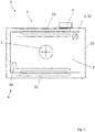
- FIG. 1 is a schematic front view of a self-cleaning oven 1 according to the invention.
- the self-cleaning oven 1 comprises an oven chamber 2 being formed by a plurality of walls 20, a heating unit 3 for heating the oven chamber 2, an optional integral light unit 6 for illuminating the oven chamber 2, and an optional fan 5 for providing air circulation inside the oven chamber 2.
- the heating unit 3 comprises an optional upper heating element 30 arranged inside the oven chamber 2 at an upper wall of the oven chamber 2 and an optional lower heating element 32 arranged inside the oven chamber 2 at a bottom wall of the oven chamber 2.
- the self-cleaning oven 1 further comprises a control unit 9 for controlling the oven 1, in particular for controlling the heating unit 3, the integral light unit 6, the fan 5 and, in addition, a sensor system 4 of the oven 1.
- the sensor system 4 comprises an optical sensor 40 which according to this exemplary embodiment is in the form of a light sensor which is capable of detecting light emitted by the integral light unit 6.
- the integral light unit 6 functions as a light source 42 of the sensor system 4.
- the light source 42 and the optical sensor 40 are arranged inside the oven chamber 2 such that the optical sensor 40 can detect light directly emitted by the light source 42 and light scattered from the walls 20 of the oven chamber 2.
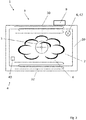
- Figure 2 is another schematic front view of the self-cleaning oven 1 shown in figure 1 , wherein the presence of smoke is indicated by means of reference sign 6.
- the smoke 6 inside the oven chamber 2 blocks light rays emitted from the light source 42 from reaching the optical sensor 40.
- the smoke 6 further blocks light rays scattered by the walls 20 from reaching the optical sensor 40. Accordingly, an illuminance detected by the optical sensor 40 is lower when smoke 6 is present than when no smoke 6 is present in the oven chamber 2.
- the denser the smoke 6 inside the oven chamber 2 the lower the illuminance detected by the optical sensor 40.
- the sensor system 4 thus, is adapted to determine optical conditions indicative of a smoke level in the oven chamber 2 based on measurement data of the optical sensor 40. Further, the control unit 9 is adapted to determine a self-cleaning time period based on the optical conditions indicative of the smoke level determined by the sensor system 4.
- the optical sensor 40 may be provided in the form of a camera.
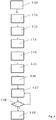
- FIG 3 is a flowchart of an embodiment of a cleaning method for cleaning the self-cleaning oven 1 as shown in figures 1 and 2 .
- an initial reference value is obtained by the optical sensor 40 (S 10) for a first reference.
- control unit 9 controls the heating unit 3 to heat the oven chamber 2 to a predefined pyrolysis self-cleaning temperature, which in this exemplary embodiment is between 480°C and 500°C (S 11).
- a first measurement value is determined by the sensor system 4 (S 12).
- the control unit 9 determines the optimal self-cleaning time period taking into account the first measurement and the three further measurements, and optionally also the initial reference value (S 16).
- control unit 9 may comprise a processor unit (not shown) which is capable of executing an algorithm which determines a distribution of the optical conditions indicative of the smoke level, which is indicative of the density of smoke 6 inside the oven chamber 2, overtime, and subsequently determines a suitable self-cleaning time period based on the determined distribution of the optical conditions indicative of the smoke level over time.
- the control unit 9 may optionally comprise a memory unit (not shown) in which optionally a lookup table is stored, based on which the self-cleaning time period can be picked with respect to the determined optical conditions indicative of the smoke level(s).
- the algorithm of the control unit 9 may further be adapted to calculate a suitable self-cleaning time period based on the values obtained by the sensor system 4 regarding the optical conditions indicative of the smoke level(s).
- the light source 42 may only be switched on when a measurement is obtained. Alternatively, the light source 42 may be illuminated over part of or even over the entire self-cleaning process.
- FIG 4 is a flowchart of another embodiment of a cleaning method for a self-cleaning oven 1.
- the cleaning method corresponds to the cleaning method described with regard to figure 3 , wherein in addition to steps S 10 to S 16, the following steps are performed: Subsequent to the first determination of the self-cleaning time period according to step S 16, after expiry of another waiting time period, another measurement is obtained (S 17), and the currently obtained optical conditions indicative of the smoke level are compared to the preceding obtained optical conditions indicative of the smoke level (S 18).
- Steps S 17 and S 18 are periodically repeated until the difference between the last two subsequent obtained optical conditions indicative of the smoke levels is smaller than a predefined threshold. If the difference is smaller than the predefined threshold, heating of the oven chamber 2 is stopped (S 19) even before the initially determined self-cleaning time period expired.
- the self-cleaning time period is updated and/or adapted based on the result of step S18 after each newly taken measurement of the smoke level.
- steps S 13 to S 16 and optionally also S 10 are not performed.
- the first first measurement value is determined by the sensor system 4 (S 12) after expiry of the starting time.
- Steps S 17 and S 18 are periodically repeated until the difference between two most recent subsequently obtained optical conditions indicative of the smoke level is smaller than a predefined threshold. If the difference is smaller than the predefined threshold, heating of the oven chamber 2 is stopped (S 19).
- the self-cleaning time period is determined in that an end point of the self-cleaning operation is defined based on the comparison with the threshold.
- FIG 5 is a schematic front view of a self-cleaning oven 1 according to another embodiment.
- the oven 1 substantially corresponds to the oven 1 as shown in figures 1 and 2 , wherein the sensor system 4 is arranged in an exhaust duct 8 of the oven chamber 2.
- the sensor system 4 comprises a light source 42 which is provided separate to the integral light unit 6 of the oven chamber 2.
- Figure 6 is a schematic front view of a self-cleaning oven 1 according to another embodiment.
- the oven 1 substantially corresponds to the oven as shown in figure 5 , wherein the light source 42 and the optical sensor 40 are not arranged on opposite sides on the same location with respect to a longitudinal direction of the exhaust duct 8 as shown in figure 5 , but are spaced apart from each other in the longitudinal direction of the exhaust duct 8.
- the optical sensor 40 and the light source 42 may be arranged at a greater distance to each other. Hence, accuracy of the sensor system according to figure 6 may be improved with respect to the embodiment shown in figure 5 .
- FIG 7 is a schematic front view of a self-cleaning oven 1 according to another embodiment.
- the oven 1 substantially corresponds to the oven as shown in figures 1 and 2 , wherein the sensor system 4 is provided in a form of a smoke detector.
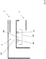
- FIG 8 is a detailed view of the sensor system 4 of the self-cleaning oven 1 as shown in figure 7 .
- the sensor system 4 is a detachable integral unit attached to the upper wall 20 of the oven chamber 2.
- the optical sensor 40 and the light source 42 are separated by a separating plate 44 such that light emitted by the light source 42 cannot directly travel to the optical sensor 40. Furthermore, both the optical sensor 40 and the light source 42 are covered by a cover 46 such that no light from outside the sensor system 4, for example emitted by the integral light unit 6 of the oven chamber 2 is able to reach the optical sensor 40. On its inner side, the cover 46 comprises a non-reflecting surface such that light emitted by the light source 42 is not scattered towards the optical sensor 40. Accordingly, when no smoke is present in the inner space of the sensor system 4, which is substantially defined by the cover 46, substantially no illuminance is detected by the optical sensor 40.
Landscapes
- Engineering & Computer Science (AREA)
- Chemical & Material Sciences (AREA)
- Combustion & Propulsion (AREA)
- Mechanical Engineering (AREA)
- General Engineering & Computer Science (AREA)
- Chemical Kinetics & Catalysis (AREA)
- Investigating Or Analysing Materials By Optical Means (AREA)
- Electric Stoves And Ranges (AREA)
- Fire-Detection Mechanisms (AREA)
Abstract
Description
- The invention relates to a self-cleaning oven for cooking food, and to a cleaning method for a self-cleaning oven.
- For cooking of food, it is well-known to use ovens. However, when cooking food in an oven, the oven chamber is exposed to soiling based on spills and leftovers from the food cooked inside the oven chamber. Manual cleaning of the oven chamber is laborious and introduces the possibility of damaging parts of the oven, for example due to use of an inadequate cleaning agent or cleaning device. In order to address the aforementioned drawbacks, ovens with self-cleaning capability have been established, wherein said self-cleaning ovens perform self-cleaning based on pyrolysis, that is by reducing food soiling to ash by means of exposing the latter to a predefined pyrolysis temperature, for example 500° C for a certain self-cleaning time period, normally about one hour to 1.5 hours. After the oven chamber has cooled down, the burned leftovers/ash can be removed from the oven chamber or can be removed by a filter.
- In ordinary self-cleaning ovens, the self-cleaning time period is constant, wherein the time period has to be defined as being long enough to provide adequate cleaning in case of heavy soiling of the oven chamber. Consequently, the constant self-cleaning time period reflect a maximum time span necessary for removing heavy soiling, and does not reflect the actual degree of soiling of the oven chamber. As self-cleaning is performed at high temperatures, heating the oven chamber to the predefined pyrolysis temperature results in high power consumption.
- In most cases, the oven chamber shows a soiling degree below or even far below a soiling level for which the constant self-cleaning time period is defined, such that the oven chamber usually is heated longer than necessary for removing the actual soiling, and energy is wasted without having any effect on the cleaning result.
- It is known to survey the actual degree of soiling in the oven chamber by means of a capacity sensor as can be derived from
US 5,343,020 A1 , or based on electrical conductivity measurements as can be derived fromUS 5,083,010 A1 , such that self-cleaning can be performed before arriving at an excessive degree of soiling of the oven chamber. - In order to reduce unnecessary energy consumption,
US 6,437,294 B2 andUS 5,286,943 A1 teach to set the pyrolysis temperature and/or the self-cleaning time period based on a type of soiling determined with respect to measurement results of a gas sensor disposed in an exhaust duct of the oven. The output of the gas sensor changes based on a chemical reaction of a catalyst material of the sensor with combustion gases being produced during pyrolysis, such as short-chained hydrocarbons and hydrogen molecules, in particular carbon monoxide. However, the aforementioned method requires comparatively complex and expensive sensor equipment, and the sensors have to be exchanged after a certain amount of chemical reaction of the catalyst has occurred. - It is an object of the present invention to provide an improved self-cleaning oven for cooking food, and an improved cleaning method for a self-cleaning oven.
- Accordingly, in one aspect, a self-cleaning oven for cooking food is suggested, comprising an oven chamber for receiving food to be cooked, a heating unit for heating the oven chamber to a predetermined temperature, a control unit for controlling the heating unit, and a sensor system for detecting presence of smoke in the oven, wherein the control unit is adapted to determine a self-cleaning time period based on the sensor system output. The self-cleaning oven is characterized in that the sensor system is adapted to determine optical conditions within the oven that are indicative of the smoke level in the oven chamber based on measurement data of an optical sensor.
- Cooking according to the present invention comprises any kind of preparation of food in the oven. For example, baking, broiling and heating food in the oven is considered to be cooking the food.
- The optical conditions which are indicative of the smoke level may be a change of the amount of smoke in the oven chamber or the difference to a reference value. These conditions are determined based on measurement data of the optical sensor and will hereinafter also simply be referred to as optical conditions.
- The measurement data which can also be referred to as measurement or measurement value can be the light intensity, the amount of light or a greyscale value. Obtaining the measurement value can also be referred to as detecting of light, in particular light intensity or amount of light, or a greyscale value.
- The expression "determining the self-cleaning time period" is understood to include predefining a duration of the self-cleaning operation, in particular a duration of heating the oven chamber by the heating unit. The expression further includes the mere definition of an end point of heating the oven chamber after the self-cleaning process has already been initiated. Moreover, the determining of the self-cleaning time period includes updating and/or adapting a (predefined) duration based on additional output of the sensor system.
- Since the sensor system is adapted to determine optical conditions within the oven that are indicative of the smoke level in the oven chamber based on measurement data of an optical sensor, the self-cleaning oven can comprise a comparatively simple and robust design. Moreover, the operating life of the sensor is not limited, as no chemical reaction is necessary for providing adequate measurement results. The optical sensor provides reliable data for determining the presence and change of the amount of smoke inside the oven chamber, as the output of the optical sensor may be substantially proportional or inversely proportional to the amount of smoke and/or a respective level of darkening in the oven chamber.
- According to an embodiment, the optical sensor is arranged in the oven chamber, preferably at an oven chamber wall, more preferably a side wall or an upper wall of the oven chamber.
- Alternatively, the optical sensor can be arranged in an exhaust duct of the oven chamber which is arranged to conduct air and/or smoke out of the oven chamber.
- According to a further embodiment, the sensor system may comprise a light source. Preferably, the light source is an integral light unit of the oven chamber or a further light unit, preferably an LED, provided separately to an integral light unit of the oven chamber. The integral light source denotes a light source which is provided to illuminate the oven chamber during normal cooking operation.
- According to one embodiment, the optical sensor may be a light sensor. In a preferred embodiment, the optical sensor is a photodetector, and particularly preferably a photodiode, wherein the light sensor is adapted to detect light emitted by the light source. In this embodiment, where the optical sensor is a light sensor, the measurement data can be the light intensity or amount of light.
- Preferably, the light sensor may be adapted to detect direct light from the light source. That is, light that is emitted by the light source and directly reaches the light sensor. Alternatively or in addition the light sensor may be adapted to detect indirect light, that is scattered light, which is emitted by the light source and scattered by a wall of the oven chamber and/or an item disposed inside the oven chamber, for example a rack, before reaching the sensor. The light sensor may further or in addition be adapted to detect an ambient light level inside the oven chamber, which is a combination of indirect and direct light.
- Alternatively or in addition, the light sensor may be adapted to detect light which is reflected by smoke particles present inside the oven chamber. In an according embodiment, the light sensor may be arranged with respect to the light source such that no direct light emitted by the light source can reach the light sensor. In this case, the output of the light sensor is based on scattered and/or reflected light only. Alternatively, the light sensor may be arranged to detect direct light emitted from the light source and/or light scattered by walls of the oven chamber. In this case, smoke inside the oven chamber may block light rays emitted by the light source such that the detected luminance at light sensor is reduced compared to a clean oven chamber when no smoke is present.
- According to another embodiment, the optical sensor may be a camera. In this case, the sensor system and/or the control unit are adapted to determine the optical conditions within the oven that are indicative of the smoke level by evaluation of the camera data. Preferably, the control unit and/or the sensor system are adapted to determine the optical conditions within the oven that are indicative of the smoke level based on an average grayscale in a picture taken by the camera, preferably with respect to a reference grayscale value. In this embodiment, the measurement data is the grayscale value of the picture taken by the camera.
- In another embodiment, the sensor system comprises a plurality of optical sensors, preferably two, three, four, five or six optical sensors, wherein preferably the sensor system may comprise at least two sensors of different types, preferably a light sensor and a camera. Alternatively, each of the sensors may be of the same type.
- According to one embodiment, the sensor system is adapted to determine the optical conditions indicative of the smoke level at predetermined times after the control unit triggered a self-cleaning operation. In particular, the measurement by the sensor will be carried out at predetermined times after triggering of the self-cleaning operation. Triggering a self-cleaning operation may be effected by the user selecting a respective option. By taking measurement data and preferably determining the optical conditions and at predetermined times, determination of the self-cleaning time period may be more accurate. In other words, the sensor system may be adapted to obtain a plurality of measurements taken at intervals after a self-cleaning operation is triggered by the control unit. Preferably, the control unit is adapted to trigger the sensor system to perform the measurements performed by the optical sensor.
- According to one embodiment, the control unit determines the self-cleaning time period based on at least two measurements taken at intervals. Preferably at least three measurements taken at intervals are used. Preferably, the control unit is adapted to determine the self-cleaning time period based on a first measurement value and at least three subsequent measurements taken at intervals. For example, the self-cleaning time period can be determined by comparing the subsequent measurements with a first measurement. If the most recently obtained measurement value is higher than the first measurement value, then the self-cleaning temperature will be maintained. If the measurement value is similar or even lower than the first measurement value, then heating unit can be switched of or at least the temperature generated by the heating unit can be reduced to cooking temperature.
- Optionally, the sensor system may be adapted to determine an initial reference value of the light sensor prior to heating the oven chamber upon triggering of a self-cleaning operation. Thereby, a reference value indicating an oven chamber without smoke being present can be obtained. Said initial reference value may be utilized for comparison with values of the light sensor obtained after pyrolysis has been initiated. This may improve accuracy of a smoke level determination.
- According to one embodiment, upon triggering of a self-cleaning operation, the control unit is adapted to trigger the heating unit to heat the oven chamber to a predetermined self-cleaning temperature. The self-cleaning temperature, which can also be referred to as pyrolysis temperature is in the range from 350° C to 750° C, more preferably 400° C to 600° C, and particularly preferably 450° C to 500° C.
- Triggering of the self-cleaning operation may be initiated by the user of the oven. In particular, the user may press a button or select the self-cleaning operation from a menu.
- The heating unit may be formed to provide heating of the oven chamber also during normal cooking operation, that is, when the oven is used to cook food. In other words, the heating unit may also constitute the integral heating unit of the oven which provides heat to the oven chamber for cooking food. Hence, the oven can merely utilize one heating unit for both cooking and self-cleaning. Alternatively, the heating unit for self-cleaning may be provided separately to the integral heating unit of the oven. Then, the oven comprises a heating unit for heating the oven chamber to the self-cleaning temperature, and a further heating unit, the integral heating unit for heating the oven chamber in normal cooking operation.
- The heating unit may comprise one or more heating elements arranged inside the oven chamber such that direct heating of the oven chamber can be provided. Alternatively or in addition, the heating unit may comprise one or more heating elements disposed outside the oven chamber, for example in an air inlet duct of the oven chamber, such that heated air may be conducted into the oven chamber and an indirect heating of the oven chamber may be provided.
- According to one embodiment, the sensor system may be adapted to determine a first measurement value after a predetermined starting time subsequent to start of heating the oven chamber to the self-cleaning temperature, wherein the predetermined starting time preferably is 10 min to 15 min from start of heating the oven chamber to the self-cleaning temperature. The first measurement value may be used to be compared with the initial reference value, which is the value when no soiling has been burned due to pyrolysis provided by the self-cleaning temperature yet in order to draw conclusions regarding a degree of soiling of the oven chamber. The first measurement value may further be utilized as a reference for comparison with subsequent measurements.
- According to one embodiment, the sensor system may be adapted to obtain at least one further measurement subsequent to obtaining the first measurement value, preferably at least two further measurements, more preferably at least three further measurements. When taking into account the at least one further measurement, drawing conclusions about the degree of soiling in the oven chamber may be more accurate, and thus, determination of the necessary self-cleaning time period may be further improved. By comparing the measurements obtained at intervals, a smoke development over time can be estimated. This may be utilized to draw conclusions about the fact that the oven is not completely cleaned.
- According to a further embodiment, the control unit may be adapted to determine the self-cleaning time period based on at least the first measurement value and the at least one further measurement. Preferably, also the initial reference value obtained prior to exposing the oven chamber to the self-cleaning temperature is taken into account for determining the self-cleaning time period.
- According to another embodiment, during a self-cleaning operation, the sensor system may be adapted to obtain measurements periodically. Preferably a waiting time between two subsequent measurements is 5 min to 15 min, preferably 10 min. Preferably, the control unit is adapted to compare subsequent measurements. Preferably, when the difference between two subsequent measurements is smaller than a predefined threshold, the control unit is adapted to trigger the heating unit to stop heating the oven chamber. The longer the oven chamber is exposed to the self-cleaning temperature, the more soiling is burned, wherein the amount of smoke, that is, the smoke level, inside the oven chamber increases proportional to the amount of soiling burned. Accordingly, when the measurements become constant or do merely slightly change between two subsequent measurements, it could be followed that between these two measurements, substantially no or merely a small amount of additional food residues, that is, remaining soiling, may have been burned. Consequently, it could be followed that further maintaining the pyrolysis cleaning temperature in the oven chamber would not lead to substantial further cleaning of the oven chamber, and the self-cleaning operation could be terminated.
- The self-cleaning oven may further comprise a fan for providing a circulating airflow inside the oven chamber and/or for venting the oven chamber. The oven chamber may further comprise an air inlet duct and/or an exhaust duct.
- In a further aspect of the invention, a cleaning method for a self-cleaning oven is suggested, comprising the steps of heating an oven chamber to a predetermined self-cleaning temperature. The cleaning method is characterized by determining optical conditions in the oven that are indicative of the smoke level in the oven chamber based on measurement data of an optical sensor and determining a self-cleaning time period based on the determined condition.
- By means of the cleaning method, the effects and advantages described with regards the self-cleaning oven may analogously be achieved.
- The step of heating the oven chamber to a predetermined self-cleaning temperature may be performed before or during the determination of the optical conditions.
- According to an embodiment, the optical sensor detects light emitted by a light source, wherein preferably the light source is an integral light unit of the oven chamber or a further light unit, preferably an LED, provided separately to an integral light unit of the oven chamber, and/or preferably the optical sensor is a light sensor, preferably a photodetector, and particularly preferably a photodiode.
- According to an embodiment, the measurement of the optical sensor is performed at predetermined times after a self-cleaning operation is triggered.
- According to an embodiment, a plurality of measurements are obtained at intervals after a self-cleaning operation is triggered.
- According to an embodiment, the self-cleaning time period is determined based on at least two measurements taken at intervals, preferably at least three measurement, wherein preferably, the self-cleaning time period is determined based on a first measurement value and at least three subsequent measurements taken at intervals.
- According to an embodiment, upon trigger of a self-cleaning operation, an initial reference value of the optical sensor is determined prior to heating the oven chamber to the self-cleaning temperature.
- According to an embodiment, upon trigger of a self-cleaning operation, the oven chamber is heated to a predetermined pyrolysis self-cleaning temperature, preferably 350° C to 750° C, more preferably 400° C to 600° C, and particularly preferably 450° C to 500° C.
- According to an embodiment, a first measurement value is determined after a predetermined starting time subsequent to the start of heating the oven chamber. Preferably, at least one further measurement is obtained subsequent to obtaining the first measurement value, which was taken after a predetermined starting time subsequent to the start of heating of the oven, wherein preferably at least two further measurements, more preferably at least three further measurements are obtained subsequent to obtaining the first measurement value.
- According to an embodiment, the self-cleaning time period is determined based on at least the first measurement value and the at least one further measurement.
- According to an embodiment, during a self-cleaning operation, measurements are obtained periodically, wherein preferably a waiting time between two subsequent measurements is 5 min to 15 min, preferably 10 min, wherein when the difference between two subsequent measurement values is smaller than a predefined threshold, heating of the oven chamber is stopped.
- According to a further embodiment, the periodical obtaining of the measurement values is performed after the self-cleaning time period has been determined.
- The present disclosure will be more readily appreciated by reference to the following detailed description when being considered in connection with the accompanying drawings in which:
-
Figure 1 is a schematic front view of a self-cleaning oven according to the invention; -
Figure 2 is another schematic front view of the self-cleaning oven shown infigure 1 ; -
Figure 3 is a flowchart of an embodiment of a cleaning method for the self-cleaning oven shown infigures 1 and2 ; -
Figure 4 is a flowchart of another embodiment of a cleaning method for a self-cleaning oven; -
Figure 5 is a schematic front view of a self-cleaning oven according to another embodiment; -
Figure 6 is a schematic front view of a self-cleaning oven according to another embodiment; -
Figure 7 is a schematic front view of a self-cleaning oven according to another embodiment; and -
Figure 8 is a detailed view of a part of the self-cleaning oven shown infigure 7 . - In the following, the invention will be explained in more detail with reference to the accompanying figures. In the figures, like elements are denoted by identical reference numerals and repeated description thereof may be omitted in order to avoid redundancies.
-
Figure 1 is a schematic front view of a self-cleaningoven 1 according to the invention. The self-cleaningoven 1 comprises anoven chamber 2 being formed by a plurality ofwalls 20, aheating unit 3 for heating theoven chamber 2, an optional integrallight unit 6 for illuminating theoven chamber 2, and anoptional fan 5 for providing air circulation inside theoven chamber 2. - In this embodiment, the
heating unit 3 comprises an optionalupper heating element 30 arranged inside theoven chamber 2 at an upper wall of theoven chamber 2 and an optionallower heating element 32 arranged inside theoven chamber 2 at a bottom wall of theoven chamber 2. - The self-cleaning
oven 1 further comprises acontrol unit 9 for controlling theoven 1, in particular for controlling theheating unit 3, theintegral light unit 6, thefan 5 and, in addition, asensor system 4 of theoven 1. - The
sensor system 4 comprises anoptical sensor 40 which according to this exemplary embodiment is in the form of a light sensor which is capable of detecting light emitted by theintegral light unit 6. Thus, theintegral light unit 6 functions as alight source 42 of thesensor system 4. - The
light source 42 and theoptical sensor 40 are arranged inside theoven chamber 2 such that theoptical sensor 40 can detect light directly emitted by thelight source 42 and light scattered from thewalls 20 of theoven chamber 2. -
Figure 2 is another schematic front view of the self-cleaningoven 1 shown infigure 1 , wherein the presence of smoke is indicated by means ofreference sign 6. Thesmoke 6 inside theoven chamber 2 blocks light rays emitted from thelight source 42 from reaching theoptical sensor 40. Thesmoke 6 further blocks light rays scattered by thewalls 20 from reaching theoptical sensor 40. Accordingly, an illuminance detected by theoptical sensor 40 is lower whensmoke 6 is present than when nosmoke 6 is present in theoven chamber 2. The denser thesmoke 6 inside theoven chamber 2, the lower the illuminance detected by theoptical sensor 40. - The
sensor system 4, thus, is adapted to determine optical conditions indicative of a smoke level in theoven chamber 2 based on measurement data of theoptical sensor 40. Further, thecontrol unit 9 is adapted to determine a self-cleaning time period based on the optical conditions indicative of the smoke level determined by thesensor system 4. - Alternatively, the
optical sensor 40 may be provided in the form of a camera. -
Figure 3 is a flowchart of an embodiment of a cleaning method for cleaning the self-cleaningoven 1 as shown infigures 1 and2 . Upon start of a self-cleaning operation triggered by thecontrol unit 9, optionally, an initial reference value is obtained by the optical sensor 40 (S 10) for a first reference. - Then, the
control unit 9 controls theheating unit 3 to heat theoven chamber 2 to a predefined pyrolysis self-cleaning temperature, which in this exemplary embodiment is between 480°C and 500°C (S 11). - After expiry of a predefined starting time period, which in this exemplary embodiment is 10 minutes, a first measurement value is determined by the sensor system 4 (S 12).
- Subsequently, three further measurements in the
oven chamber 2 are obtained at intervals by thesensor system 4, wherein the time period between two subsequent measurements corresponds to a waiting time, which in this exemplary embodiment is 10 minutes (S 13 to S 15). - The
control unit 9 then determines the optimal self-cleaning time period taking into account the first measurement and the three further measurements, and optionally also the initial reference value (S 16). - In this regard, the
control unit 9 may comprise a processor unit (not shown) which is capable of executing an algorithm which determines a distribution of the optical conditions indicative of the smoke level, which is indicative of the density ofsmoke 6 inside theoven chamber 2, overtime, and subsequently determines a suitable self-cleaning time period based on the determined distribution of the optical conditions indicative of the smoke level over time. Thecontrol unit 9 may optionally comprise a memory unit (not shown) in which optionally a lookup table is stored, based on which the self-cleaning time period can be picked with respect to the determined optical conditions indicative of the smoke level(s). Alternatively or in addition, the algorithm of thecontrol unit 9 may further be adapted to calculate a suitable self-cleaning time period based on the values obtained by thesensor system 4 regarding the optical conditions indicative of the smoke level(s). - The
light source 42 may only be switched on when a measurement is obtained. Alternatively, thelight source 42 may be illuminated over part of or even over the entire self-cleaning process. -
Figure 4 is a flowchart of another embodiment of a cleaning method for a self-cleaningoven 1. The cleaning method corresponds to the cleaning method described with regard tofigure 3 , wherein in addition to steps S 10 toS 16, the following steps are performed:
Subsequent to the first determination of the self-cleaning time period according to stepS 16, after expiry of another waiting time period, another measurement is obtained (S 17), and the currently obtained optical conditions indicative of the smoke level are compared to the preceding obtained optical conditions indicative of the smoke level (S 18). - Steps S 17 and
S 18 are periodically repeated until the difference between the last two subsequent obtained optical conditions indicative of the smoke levels is smaller than a predefined threshold. If the difference is smaller than the predefined threshold, heating of theoven chamber 2 is stopped (S 19) even before the initially determined self-cleaning time period expired. - In an exemplary embodiment, the self-cleaning time period is updated and/or adapted based on the result of step S18 after each newly taken measurement of the smoke level.
- According to an alternative embodiment, steps
S 13 toS 16 and optionally also S 10 are not performed. Hence, in an exemplary embodiment of a cleaning method for a self-cleaning oven according to the invention, upon trigger of a self-cleaning operation, the first first measurement value is determined by the sensor system 4 (S 12) after expiry of the starting time. - Afterwards, after expiry of the waiting time period, another measurement is obtained (S 17), and the currently obtained optical conditions indicative of the smoke level are compared to the preceding obtained optical conditions indicative of the smoke level (S 18).
- Steps S 17 and
S 18 are periodically repeated until the difference between two most recent subsequently obtained optical conditions indicative of the smoke level is smaller than a predefined threshold. If the difference is smaller than the predefined threshold, heating of theoven chamber 2 is stopped (S 19). - In this case, the self-cleaning time period is determined in that an end point of the self-cleaning operation is defined based on the comparison with the threshold.
-
Figure 5 is a schematic front view of a self-cleaningoven 1 according to another embodiment. Theoven 1 substantially corresponds to theoven 1 as shown infigures 1 and2 , wherein thesensor system 4 is arranged in anexhaust duct 8 of theoven chamber 2. Thesensor system 4 comprises alight source 42 which is provided separate to theintegral light unit 6 of theoven chamber 2. -
Figure 6 is a schematic front view of a self-cleaningoven 1 according to another embodiment. Theoven 1 substantially corresponds to the oven as shown infigure 5 , wherein thelight source 42 and theoptical sensor 40 are not arranged on opposite sides on the same location with respect to a longitudinal direction of theexhaust duct 8 as shown infigure 5 , but are spaced apart from each other in the longitudinal direction of theexhaust duct 8. Compared to the embodiment shown infigure 5 , theoptical sensor 40 and thelight source 42 may be arranged at a greater distance to each other. Hence, accuracy of the sensor system according tofigure 6 may be improved with respect to the embodiment shown infigure 5 . -
Figure 7 is a schematic front view of a self-cleaningoven 1 according to another embodiment. Theoven 1 substantially corresponds to the oven as shown infigures 1 and2 , wherein thesensor system 4 is provided in a form of a smoke detector. -
Figure 8 is a detailed view of thesensor system 4 of the self-cleaningoven 1 as shown infigure 7 . Thesensor system 4 is a detachable integral unit attached to theupper wall 20 of theoven chamber 2. - The
optical sensor 40 and thelight source 42 are separated by a separatingplate 44 such that light emitted by thelight source 42 cannot directly travel to theoptical sensor 40. Furthermore, both theoptical sensor 40 and thelight source 42 are covered by acover 46 such that no light from outside thesensor system 4, for example emitted by theintegral light unit 6 of theoven chamber 2 is able to reach theoptical sensor 40. On its inner side, thecover 46 comprises a non-reflecting surface such that light emitted by thelight source 42 is not scattered towards theoptical sensor 40. Accordingly, when no smoke is present in the inner space of thesensor system 4, which is substantially defined by thecover 46, substantially no illuminance is detected by theoptical sensor 40. In case of smoke entering the inner space of thecover 46, light rays emitted by thelight source 42 are reflected by smoke particles and, thus, directed to theoptical sensor 40, such that theoptical sensor 40 detects a certain illuminance and a change in illuminance, respectively. - It will be obvious for a person skilled in the art that these embodiments and items only depict examples of a plurality of possibilities. Hence, the embodiments shown here should not be understood to form a limitation of these features and configurations. Any possible combination and configuration of the described features can be chosen according to the scope of the invention.
-
- 1
- oven
- 2
- oven chamber
- 20
- wall
- 3
- heating unit
- 30
- upper heating element
- 32
- lower heating element
- 4
- sensor system
- 40
- optical sensor
- 42
- light source
- 44
- separating plate
- 46
- cover
- 5
- fan
- 6
- integral light unit
- 7
- air inlet duct
- 8
- exhaust duct
- 9
- control unit
Claims (15)
- A cleaning method for a self-cleaning oven (1), comprising- heating an oven chamber (2) to a predetermined self-cleaning temperature;
characterized by- determining optical conditions within the oven (1) that are indicative of the smoke level in the oven chamber (2) based on measurement data of an optical sensor (40)- determining a self-cleaning time period based on the determined conditions. - The method according to claim 1, wherein the optical sensor (40) detects light emitted by a light source (42).
- The method according to claim 1 or 2, wherein a plurality of measurements is taken by the optical sensor (40) at intervals after a self-cleaning operation is triggered.
- The method according to any one of the preceding claims, wherein the self-cleaning time period is determined based on at least two measurements of the optical sensor taken at intervals, preferably at least three measurements, wherein preferably, the self-cleaning time period is determined based on a first measurement value and at least three subsequent measurements taken at intervals.
- The method according to any one of the preceding claims, wherein upon trigger of a self-cleaning operation, an initial reference value of the optical sensor (40) is determined prior to heating the oven chamber (2) to the self-cleaning temperature.
- The method according to any one of the preceding claims, wherein upon trigger of a self-cleaning operation, the oven chamber (2) is heated to a predetermined pyrolysis self-cleaning temperature of preferably 350° C to 750° C, more preferably 400° C to 600° C, and particularly preferably 450° C to 500° C.
- The method according to any one of the preceding claims, wherein a first measurement value is taken after a predetermined starting time subsequent to start of heating the oven chamber (2).
- The method according to claim 7, wherein at least one further measurement value is taken subsequent to obtaining the first measurement value, wherein preferably at least two further measurement values, more preferably at least three further measurement values are taken subsequent to taking the initial a first measurement value.
- The method according to the preceding claim, wherein the self-cleaning time period is determined based on at least the first measurement value and the at least one further measurement value.
- The method according to any one of the preceding claims, wherein during a self-cleaning operation, measurement values are taken periodically, wherein preferably a waiting time between two subsequent measurements is 5 min to 15 min, preferably 10 min, wherein when the difference between two subsequent measurement values is smaller than a predefined threshold, heating of the oven chamber (2) is stopped.
- A self-cleaning oven (1) for cooking food, characterized in that it is adapted to perform a cleaning method according to any one of the preceding claims.
- The self-cleaning oven according to claim 11, comprising
an oven chamber (2) for receiving food to be cooked, a heating unit (3) for heating the oven chamber (2) to a predetermined temperature, a control unit (9) for controlling the heating unit (3), and a sensor system (4) for detecting presence of smoke in the oven (1), wherein the control unit (9) is adapted to determine a self-cleaning time period based on sensor system output, wherein the sensor system (4) is adapted to determine optical conditions within the oven (1) that are indicative of the smoke level in the oven chamber (2) based on measurement data of an optical sensor (40). - The self-cleaning oven (1) according to claim 11 or 12, wherein the sensor system (4) comprises a light source (42), wherein preferably the light source (42) is an integral light unit (6) of the oven chamber (2) or a further light unit, preferably an LED, provided separately to an integral light unit (6) of the oven chamber (2).
- The self-cleaning oven (1) according to any one of claims 11 to 13, wherein the optical sensor (40) is a light sensor, preferably a photodetector, and particularly preferably a photodiode, wherein the light sensor is adapted to detect light emitted by the light source (42).
- The self-cleaning oven (1) according to any one claims 11 to 14, wherein the control unit (9) is adapted to trigger the sensor system (4) to perform measurements.
Priority Applications (1)
| Application Number | Priority Date | Filing Date | Title |
|---|---|---|---|
| EP20155518.2A EP3862634A1 (en) | 2020-02-05 | 2020-02-05 | Self-cleaning oven for cooking food, and cleaning method for a self-cleaning oven |
Applications Claiming Priority (1)
| Application Number | Priority Date | Filing Date | Title |
|---|---|---|---|
| EP20155518.2A EP3862634A1 (en) | 2020-02-05 | 2020-02-05 | Self-cleaning oven for cooking food, and cleaning method for a self-cleaning oven |
Publications (1)
| Publication Number | Publication Date |
|---|---|
| EP3862634A1 true EP3862634A1 (en) | 2021-08-11 |
Family
ID=69468515
Family Applications (1)
| Application Number | Title | Priority Date | Filing Date |
|---|---|---|---|
| EP20155518.2A Withdrawn EP3862634A1 (en) | 2020-02-05 | 2020-02-05 | Self-cleaning oven for cooking food, and cleaning method for a self-cleaning oven |
Country Status (1)
| Country | Link |
|---|---|
| EP (1) | EP3862634A1 (en) |
Cited By (2)
| Publication number | Priority date | Publication date | Assignee | Title |
|---|---|---|---|---|
| CN115568770A (en) * | 2022-11-01 | 2023-01-06 | 广东海新智能厨房股份有限公司 | Intelligent heating control method, device, equipment and medium for oven |
| EP4202309A1 (en) * | 2021-12-22 | 2023-06-28 | Whirlpool Corporation | Method for cleaning a viewport glass of a camera, system for performing a dedicated self-cleaning cycle for a camera, and a computer-readable medium comprising instructions therefor |
Citations (8)
| Publication number | Priority date | Publication date | Assignee | Title |
|---|---|---|---|---|
| US5083010A (en) | 1990-05-31 | 1992-01-21 | Bosch-Siemens Hausgerate Gmbh | Pyrolytic self-cleaning stove |
| US5286943A (en) | 1991-08-19 | 1994-02-15 | Bosch-Siemens Hausgeraete | Sensor-controlled oven pyrolysis utilizing fuzzy logic control |
| US5343020A (en) | 1991-08-19 | 1994-08-30 | Bosch-Siemens Hausgeraete Gmbh | Stove with a capacitive sailing sensor and sensor-controlled starting of pyrolysis |
| US6437294B2 (en) | 2000-06-02 | 2002-08-20 | Whirlpool Corporation | Pyrolytic self-cleaning oven |
| DE10128024A1 (en) * | 2001-06-08 | 2003-01-02 | Bsh Bosch Siemens Hausgeraete | Controlling self-cleaning of cooker involves Controlling start and/or duration of cleaning process depending on optical radiation from light source detected by sensor in oven housing |
| KR20110011817A (en) * | 2009-07-29 | 2011-02-09 | 엘지전자 주식회사 | Oven range with contamination detector |
| WO2014102074A1 (en) * | 2012-12-26 | 2014-07-03 | Arcelik Anonim Sirketi | Pyrolytic oven |
| DE102017206058A1 (en) * | 2017-04-10 | 2018-10-11 | BSH Hausgeräte GmbH | Determining a degree of contamination in a cooking chamber |
-
2020
- 2020-02-05 EP EP20155518.2A patent/EP3862634A1/en not_active Withdrawn
Patent Citations (8)
| Publication number | Priority date | Publication date | Assignee | Title |
|---|---|---|---|---|
| US5083010A (en) | 1990-05-31 | 1992-01-21 | Bosch-Siemens Hausgerate Gmbh | Pyrolytic self-cleaning stove |
| US5286943A (en) | 1991-08-19 | 1994-02-15 | Bosch-Siemens Hausgeraete | Sensor-controlled oven pyrolysis utilizing fuzzy logic control |
| US5343020A (en) | 1991-08-19 | 1994-08-30 | Bosch-Siemens Hausgeraete Gmbh | Stove with a capacitive sailing sensor and sensor-controlled starting of pyrolysis |
| US6437294B2 (en) | 2000-06-02 | 2002-08-20 | Whirlpool Corporation | Pyrolytic self-cleaning oven |
| DE10128024A1 (en) * | 2001-06-08 | 2003-01-02 | Bsh Bosch Siemens Hausgeraete | Controlling self-cleaning of cooker involves Controlling start and/or duration of cleaning process depending on optical radiation from light source detected by sensor in oven housing |
| KR20110011817A (en) * | 2009-07-29 | 2011-02-09 | 엘지전자 주식회사 | Oven range with contamination detector |
| WO2014102074A1 (en) * | 2012-12-26 | 2014-07-03 | Arcelik Anonim Sirketi | Pyrolytic oven |
| DE102017206058A1 (en) * | 2017-04-10 | 2018-10-11 | BSH Hausgeräte GmbH | Determining a degree of contamination in a cooking chamber |
Cited By (3)
| Publication number | Priority date | Publication date | Assignee | Title |
|---|---|---|---|---|
| EP4202309A1 (en) * | 2021-12-22 | 2023-06-28 | Whirlpool Corporation | Method for cleaning a viewport glass of a camera, system for performing a dedicated self-cleaning cycle for a camera, and a computer-readable medium comprising instructions therefor |
| US12010409B2 (en) | 2021-12-22 | 2024-06-11 | Whirlpool Corporation | Camera view port dedicated self cleaning cycles |
| CN115568770A (en) * | 2022-11-01 | 2023-01-06 | 广东海新智能厨房股份有限公司 | Intelligent heating control method, device, equipment and medium for oven |
Similar Documents
| Publication | Publication Date | Title |
|---|---|---|
| CN110462292B (en) | run cookware | |
| US10502430B1 (en) | Particulates detection in a cooking instrument | |
| US20160033140A1 (en) | Oven appliance with interior cleanliness sensor | |
| JP2017040430A (en) | Range food | |
| WO2014102074A1 (en) | Pyrolytic oven | |
| CN103328897A (en) | Extractor hood | |
| US20240093875A1 (en) | Method for operating a cooking appliance, and cooking appliance | |
| EP3867576B1 (en) | An exhaust hood comprising a temperature sensor | |
| ES2991310T3 (en) | Procedure for determining the duration of a cleaning cycle | |
| US20220151431A1 (en) | Machine vision cook timer | |
| EP1172612B1 (en) | System for controlling the duration of a self-clean cycle in an oven | |
| JP5044339B2 (en) | Cooker with grill | |
| EP3767183A1 (en) | Method for recognising pollution of a domestic appliance and pol-lution recognition system for a domestic appliance | |
| CN110730887B (en) | Heating cooker and method for controlling heating cooker | |
| CN115342394A (en) | Control method, kitchen appliance and storage medium | |
| JPWO2019208342A1 (en) | Cooker | |
| JP2005207694A (en) | Cooker | |
| CN109237547B (en) | Smoke stove linkage control method and smoke stove linkage system | |
| JP5484257B2 (en) | Cooker | |
| JP2010071615A (en) | Heating cooker | |
| TWI673458B (en) | Range hood with image detection and control method thereof | |
| TR202001684A2 (en) | Self-cleaning oven for cooking food, and cleaning method for a self-cleaning oven. | |
| JP7075239B2 (en) | grill | |
| JP4862710B2 (en) | Cooker | |
| KR20230158772A (en) | Apparatus and method for recognizing a cooking situation |
Legal Events
| Date | Code | Title | Description |
|---|---|---|---|
| PUAI | Public reference made under article 153(3) epc to a published international application that has entered the european phase |
Free format text: ORIGINAL CODE: 0009012 |
|
| STAA | Information on the status of an ep patent application or granted ep patent |
Free format text: STATUS: THE APPLICATION HAS BEEN PUBLISHED |
|
| AK | Designated contracting states |
Kind code of ref document: A1 Designated state(s): AL AT BE BG CH CY CZ DE DK EE ES FI FR GB GR HR HU IE IS IT LI LT LU LV MC MK MT NL NO PL PT RO RS SE SI SK SM TR |
|
| STAA | Information on the status of an ep patent application or granted ep patent |
Free format text: STATUS: REQUEST FOR EXAMINATION WAS MADE |
|
| 17P | Request for examination filed |
Effective date: 20220208 |
|
| RBV | Designated contracting states (corrected) |
Designated state(s): AL AT BE BG CH CY CZ DE DK EE ES FI FR GB GR HR HU IE IS IT LI LT LU LV MC MK MT NL NO PL PT RO RS SE SI SK SM TR |
|
| STAA | Information on the status of an ep patent application or granted ep patent |
Free format text: STATUS: EXAMINATION IS IN PROGRESS |
|
| 17Q | First examination report despatched |
Effective date: 20230206 |
|
| STAA | Information on the status of an ep patent application or granted ep patent |
Free format text: STATUS: THE APPLICATION IS DEEMED TO BE WITHDRAWN |
|
| 18D | Application deemed to be withdrawn |
Effective date: 20240903 |