EP3862528A1 - Imloch-bohrgerät und verfahren zum erstellen einer bohrung - Google Patents
Imloch-bohrgerät und verfahren zum erstellen einer bohrung Download PDFInfo
- Publication number
- EP3862528A1 EP3862528A1 EP20155449.0A EP20155449A EP3862528A1 EP 3862528 A1 EP3862528 A1 EP 3862528A1 EP 20155449 A EP20155449 A EP 20155449A EP 3862528 A1 EP3862528 A1 EP 3862528A1
- Authority
- EP
- European Patent Office
- Prior art keywords
- drill head
- bracing
- drilling device
- drilling
- frame section
- Prior art date
- Legal status (The legal status is an assumption and is not a legal conclusion. Google has not performed a legal analysis and makes no representation as to the accuracy of the status listed.)
- Granted
Links
Images



Classifications
-
- E—FIXED CONSTRUCTIONS
- E21—EARTH OR ROCK DRILLING; MINING
- E21B—EARTH OR ROCK DRILLING; OBTAINING OIL, GAS, WATER, SOLUBLE OR MELTABLE MATERIALS OR A SLURRY OF MINERALS FROM WELLS
- E21B4/00—Drives for drilling, used in the borehole
- E21B4/18—Anchoring or feeding in the borehole
-
- E—FIXED CONSTRUCTIONS
- E02—HYDRAULIC ENGINEERING; FOUNDATIONS; SOIL SHIFTING
- E02D—FOUNDATIONS; EXCAVATIONS; EMBANKMENTS; UNDERGROUND OR UNDERWATER STRUCTURES
- E02D7/00—Methods or apparatus for placing sheet pile bulkheads, piles, mouldpipes, or other moulds
- E02D7/28—Placing of hollow pipes or mould pipes by means arranged inside the piles or pipes
-
- E—FIXED CONSTRUCTIONS
- E21—EARTH OR ROCK DRILLING; MINING
- E21B—EARTH OR ROCK DRILLING; OBTAINING OIL, GAS, WATER, SOLUBLE OR MELTABLE MATERIALS OR A SLURRY OF MINERALS FROM WELLS
- E21B7/00—Special methods or apparatus for drilling
- E21B7/20—Driving or forcing casings or pipes into boreholes, e.g. sinking; Simultaneously drilling and casing boreholes
- E21B7/208—Driving or forcing casings or pipes into boreholes, e.g. sinking; Simultaneously drilling and casing boreholes using down-hole drives
Definitions
- the invention relates to a down-the-hole drilling device for creating a hole in the ground, with a drill head for removing soil material, a drill string at the lower end of which the drill head is attached, a rotary drive device for rotating the drill string with the drill head, a bracing device which is connected to a first frame section is arranged and designed for radial bracing of the downhole drilling device radially to the borehole wall, and at least one adjusting cylinder for adjusting the drill head in an axial direction, according to the preamble of claim 1.
- the invention further relates to a method for creating a bore in the ground, in which, to form the bore, soil material is removed by means of a drill head which is attached to a lower end of a drill string which is driven in rotation by means of a rotary drive device, a first frame section of the in-hole Drilling device is braced radially to a borehole wall by means of a bracing device, and the drill head is adjusted in an axial direction by means of at least one adjusting cylinder, according to the preamble of claim 12.
- Down-the-hole drilling devices are used in particular when drilling holes in the ground with a larger drilling diameter, which can typically be 1 meter to several meters.
- the downhole drilling device has a drill head which is set in rotation by means of a rotary drive, which directly is arranged on the frame of the downhole drilling device and is thus located in the borehole itself.
- a rotary drive which directly is arranged on the frame of the downhole drilling device and is thus located in the borehole itself.
- one or more adjusting cylinders for axially displacing the drill head are also arranged.
- the frame of the down-the-hole drilling device is braced directly against the borehole wall by means of a bracing device. If the at least one feed cylinder is axially extended to the maximum, the tension is released and the frame of the downhole drilling device with the rotary drive is moved down to the drill head by retracting the feed cylinder and adjusting the cable suspension. The downhole drilling device can then be fixed in position on the borehole wall again by the bracing device, so that a further drilling step can be carried out by axially extending the feed cylinder.
- Down-the-hole drilling devices are known in which the rotary drive is arranged directly on the drill head.
- the feed cylinders for adjusting the drill head are located above the rotary drive and below the bracing device, so that the axial flow of force for the feed pressure is directed through the area of the rotary drive. This represents a load on the area with the rotary drive.
- the rotary drive in this arrangement is arranged close to the drill head and thus to the removal area, so that the rotary drive is exposed to increased shocks and vibrations during operation of the drill head, especially when removing rocky soil layers.
- a support pipe for forming the borehole wall can also be introduced via a casing machine.
- a generic downhole drilling device and a generic method are based on the EP 2 615 239 B1 emerged.
- the rotary drive and the axial feed cylinder are arranged above the bracing device.
- the rotary drive is mounted at a greater distance from the drill head, so that the rotary drive is less exposed to direct loads when the rock material is removed by the drill head.
- the feed cylinders are located above the rotary drive and above the bracing device, so that once again a power flow occurs through the rotary drive, which creates an additional load of the rotary actuator.
- the placement of the axial feed cylinder at the upper end of the down-the-hole drilling device leads to a relatively large drive train, which must be dimensioned correspondingly large to ensure sufficient torsional rigidity. Together with the length of the drill drive string, this results in a relatively large, in particular heavy, down-the-hole drilling device.
- bracing device is formed from two sub-devices.
- a first bracing device is located on an upper end region of the drilling device, while a second bracing device is attached to a lower end region of the drilling device.
- the rotary drive and the feed device are arranged in the intermediate area between the two bracing devices.
- a double arrangement of bracing devices is mandatory, which in principle leads to an increase in weight, size and costs.
- the invention has for its object to provide a downhole drill having a particularly compact and robust construction. Another object of the invention is to provide a method for creating a bore with such a drilling device.
- the drilling device according to the invention is characterized in that the at least one adjusting cylinder is arranged below the bracing device, which is supported on the one hand on the first frame section and on the other hand extends towards the drill head, and in that the rotary drive device is arranged above the bracing device.
- a basic idea of the invention is to arrange the at least one adjusting cylinder for the feed drive below the bracing device, while the rotary drive is arranged above the first frame section with the bracing device. Due to the arrangement of the at least one adjusting cylinder of the axial Feed drive directly between the bracing device and the drill head, a direct flow of force to the drill head can take place.
- the at least one adjusting cylinder is supported on the first frame section with the bracing device directly and thus against the surrounding borehole wall. Such high forces can be applied directly to the drill head, so that even rocky layers of rock can be machined with a high pressure or feed force.
- the at least one adjusting cylinder can be supported directly on the drill head.
- the rotary drive device is removed from this axial force flow, the rotary drive device being mounted on the first frame section above the bracing device. This results in a gentle arrangement of the rotary drive device and thus an overall robust construction of the drilling device.
- the rotary drive device is mounted on the fixed frame and is consequently axially fixed. This simplifies the energy supply of the rotary drive device during the drilling step and also simplifies the overall structure of the drilling device.
- the rotary drive device is arranged at a distance from the drill head, so that the rotary drive device with the sensitive bearings and seals is no longer directly exposed to the mechanical loads of the area to be removed.
- a preferred embodiment of the down-the-hole drilling device consists in that a plurality of actuating cylinders are arranged on the first frame section, distributed evenly over the circumference.
- the first frame section is preferably designed in the form of a ring.
- two, three or four or possibly even more adjusting cylinders can be arranged in a ring around the drilling axis.
- the adjusting cylinders form the feed device and are aligned approximately parallel to the drilling axis.
- the clamping device has one or more radially directed clamping cylinders having.
- the clamping cylinders are supported on the one hand on the first frame section, while a contact element for contacting the borehole wall is provided and arranged on the free side of the clamping cylinder.
- the borehole wall can be understood directly as the pending soil or, if appropriate, an inner side of a support tube or a casing which is also introduced into the borehole in order to support it.
- clamping cylinders arranged in the transverse or even in the axial direction can also be provided, which can apply radial clamping forces for clamping the drilling device in the borehole via a corresponding mechanism, for example a lever mechanism.
- the cylinders used can be actuated with any suitable fluid.
- the at least one adjusting cylinder for axially adjusting the drill head and / or the at least one clamping cylinder of the clamping device is designed as a hydraulic cylinder.
- the cylinders are supplied with hydraulic oil in a closed circuit from outside the borehole by a hydraulic system.
- the hydraulic oil can also be used to operate the rotary drive device and other components of the downhole drilling device.
- the rotary drive device can be designed in any way.
- the rotary drive device has a drive shaft along which the drill string is axially displaceably mounted, and that axially extending drive strips are arranged on an outside of the drive shaft to transmit a drive torque.
- corresponding drive strips are provided on an inside of the at least regionally tubular drill string so that torque can be transmitted between the drive strips, while at the same time ensuring that the drill string can be axially displaced relative to the drive shaft.
- a hollow drive wheel can also be provided in which the drill string is mounted in a rotationally fixed but axially displaceable manner.
- the rotary drive device has one or more rotary drives which are mounted on the first frame section. With several rotary actuators these can be attached to the preferably ring-shaped first frame section, in particular evenly distributed around the drilling axis.
- the rotary drives can jointly drive the drive shaft via corresponding drive pinions or a gear arrangement and thus transmit the torque to the drill string.
- a further expedient embodiment of the invention can be seen in the fact that a conveying device is provided with which soil material removed from the drill head can be carried away to the outside of the bore.
- a corresponding feed pump can be provided on the drilling device itself or outside the borehole.
- a conveying line is preferably provided along the drilling device, via which the cuttings removed can be carried away from the drill head upwards along the frame and out of the borehole.
- the delivery line can run partially or entirely in the drill string, which can be tubular.
- the drilling cuttings can also be conveyed away in an air lifting process, in which air is introduced into the borehole via a supply line in order to effect removal of the drilling cuttings during the subsequent upward flow in the conveying line.
- the downhole drilling device can in particular be guided in the ground via a rod.
- a connecting device for a support cable is arranged on an upper end section of the frame of the downhole drilling device.
- a hoist winch for raising and lowering the drilling device can be arranged outside the borehole.
- the invention further comprises a drilling system for creating a borehole in the ground, the drilling system having the above-described down-the-hole drilling device and this being suspended by means of a support device.
- the support device can in particular have a support cable with a hoist winch.
- a casing machine is provided with which casing that forms the borehole wall can be introduced into the ground at the same time or offset in time to create the borehole.
- the piping is in particular by one or more Support pipes formed, which are introduced into the ground via the casing machine.
- the tubing can lead or lag the drill head depending on the soil conditions.
- the tubing serves in particular to stabilize the borehole wall so that the downhole drilling device can reliably support itself on it.
- piping is not absolutely necessary.
- a further advantageous embodiment of the invention consists in that the support device is arranged on the ground or on a floating body on a water surface.
- the support device can in particular be movable and in particular have a crawler track.
- the floating body can be designed as a pontoon or as a ship, so that the drilling system can also be used to drill a hole on the bed of a water body.
- the down-the-hole drilling device can preferably have a second frame section which is axially fixed but rotatably mounted relative to the drill head.
- this second frame section which preferably has an annular or plate-like flange, in particular the extendable ends of the adjusting cylinders of the feed drive can be articulated.
- a second bracing device which can be axially displaced with the drill head, can also be provided on the second frame section.
- the downhole drilling device can thus be fixed in the drill hole by the second bracing device.
- the first bracing device on the first frame section can then be released and, by retracting the adjusting cylinder, the first frame section with the rotary drive device and, if necessary, further components can be adjusted.
- a further drilling step can be carried out.
- the down-the-hole drilling device can be constructed in a modular manner, so that a relatively simple adaptation to different bore diameters can take place.
- the method according to the invention is characterized in that at least one adjusting cylinder is arranged below the bracing device, which on the one hand is supported on the first frame section and on the other hand extends towards the drill head, the drill head when removing soil material with the at least one adjusting cylinder in the direction of the soil is pressed, and that the rotary drive device with which the drill string is driven in rotation is arranged above the bracing device.
- the method according to the invention can in particular be carried out with the down-the-hole drilling device which has been described above.
- the advantages described above can be achieved in this case.
- a preferred variant of the method of the invention consists in that a casing is introduced into the ground at the same time as or offset in time for the creation of the borehole, which casing forms the borehole wall.
- a casing machine known in principle can be used for this purpose.
- the tubing which is formed from a single support tube or from a plurality of support tubes that can be connected to one another, can be introduced at the same height as the drill head or lead or lag behind it.
- the downhole drilling device when or after the downhole drilling device is withdrawn from the bore, it is filled with a hardenable compound to form a foundation element.
- the mass can in particular be a concrete suspension which hardens in the drilled hole to form a foundation element.
- a prefabricated foundation element e.g. a steel pipe, is set into it and that the remaining annular gap to the bore wall is filled with a hardenable compound.
- one or more reinforcing elements preferably steel girders or a reinforcing cage, can be inserted into the bore or the annular gap.
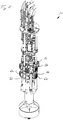
- a first down-the-hole drilling device 10 according to the invention is shown.
- This has a scaffold-like frame 12 which comprises a first annular frame section 14.
- a rotary drive device 40 is arranged on the upper side of this plate-like first frame section 14, which in the illustrated embodiment is formed by three hydraulic rotary drives 42, which are arranged evenly distributed around a longitudinal or drilling axis of the downhole drilling device 10.
- the bracing device 50 is attached to the underside of the first frame section 14 and is designed for radial bracing and fixing of the down-the-hole drilling device 10 with respect to a borehole wall.
- the ring-shaped clamping device 50 has six radially directed clamping cylinders, which cannot be seen, on the outside of which stamp-like clamping plates 52 are attached.
- the clamping cylinders with the clamping plates 52 are evenly distributed around the longitudinal or drilling axis of the downhole drilling device 10.
- An upper frame section 15 is arranged at the upper end of the frame 12.
- a plate-shaped, ring-like intermediate section 16 is arranged between the upper frame section 15 and the first frame section 14 below, which is connected via vertically directed connecting struts 18 on the one hand to the first frame section 14 and on the other hand upwards to the upper frame section 15.
- a connecting device 28 for a cable suspension of the downhole drilling device 10 and two line feeds 29 to the side are arranged in the middle.
- the line feeds 29 serve, on the one hand, to feed a hydraulic hose line and, on the other hand, to feed and hold a drilling suspension discharge line.
- Control components 19 can be arranged on the plate-like intermediate section 16.
- the upper area of the frame 12 with the first frame section 14, the upper frame section 15 and the intermediate section 16 can be constructed in a modular manner, so that the downhole drilling device 10 can be easily adapted to different borehole sizes and areas of application.
- the feed device 70 with hydraulic actuating cylinders 72 is arranged below the bracing device 50 on the first frame section 14.
- the cylinder housings of the actuating cylinders 72 are fastened to the first frame section 14.
- the actuating cylinders 72 are articulated to a second annular, plate-like second frame section 20.
- the annular second frame portion 20 is attached to an outside of a tubular bearing sleeve 24, in which a tubular drill string 38, which is only partially in the Figures 3 and 4th is visible, rotatable but axially fixed.
- a drill head 30 is attached to the lower end of the drill string 38.
- the drill head 30 has a central pilot tip 32 and radially directed removal elements 34 which are designed to remove soil material.
- the second frame section 20 is mounted so as to be axially adjustable with respect to the first frame section 14.
- a drive shaft 44 of the rotary drive device 40 projects into the tubular drill string 30.
- the drive shaft 44 has outer, axially extending drive strips 46 which, for torque transmission, interact with corresponding inner drive strips on the inside of the tubular drill string 38.
- the drill string 38 is driven to rotate with the drill head 30 via the drive shaft 44, so that it can remove soil material.
- the downhole drilling device 10 is shown in a state in which the drill head 30 is axially retracted.
- the downhole drilling device 10 can be fixed in a borehole, in particular a support tube in the borehole, by means of the clamping device 50 by radially extending the clamping plates 52 against a borehole wall.
- the feed device 70 can then be actuated with the drill head 30 rotating, the actuating cylinders 72 extending downwards.
- the second frame section 20 with the bearing sleeve 24 and the drill head 30 mounted thereon is moved downwards in order to bring about a corresponding propulsion during drilling.
- the bracing by the bracing device 50 can be released by moving the tensioning plates 52 back.
- the upper region of the frame 12 can be moved downwards by retracting the adjusting cylinder 72 and slackening a support cable attached to the connecting device 28 until the axially retracted state according to FIG Figures 1 and 2 is reached again.
- a further drilling step can be carried out.
- Soil material occurring during drilling can be discharged through the frame 12 via the hollow drill string 38, the hollow drive shaft 44 by means of a suction pump 36 as a conveyor 35 and transported outside the borehole via a partially shown conveyor line 37.
- the second frame section 20 with the bearing sleeve 24 can have a third frame section 27, which can be mounted linearly displaceably via linear guides 26 which are fixedly attached to the first frame section 14 and which are directed downwards.
- the linear guides 26 can absorb torsional forces in the circumferential direction, so that the actuating cylinders 72 are relieved of transverse forces.
- FIGS Figures 5 and 6th Another embodiment of the downhole drilling device 10 according to the invention is shown. This basically has the same components and the same structure as the downhole drilling device 10 according to FIGS Figures 1 to 4 .
- a second tensioning device 60 with radially extendable tensioning plates 62 is arranged on the third frame section 27, which can be displaced with the drill head 30 and which is annular in shape.
- the down-the-hole drilling device 10 can thus be braced and fixed in relation to the borehole wall at any point in time.
Landscapes
- Engineering & Computer Science (AREA)
- Life Sciences & Earth Sciences (AREA)
- Mining & Mineral Resources (AREA)
- Geology (AREA)
- General Life Sciences & Earth Sciences (AREA)
- Environmental & Geological Engineering (AREA)
- Physics & Mathematics (AREA)
- Fluid Mechanics (AREA)
- Geochemistry & Mineralogy (AREA)
- General Engineering & Computer Science (AREA)
- Structural Engineering (AREA)
- Civil Engineering (AREA)
- Paleontology (AREA)
- Mechanical Engineering (AREA)
- Earth Drilling (AREA)
Abstract
Description
- Die Erfindung betrifft ein Imloch-Bohrgerät zum Erstellen einer Bohrung im Boden, mit einem Bohrkopf zum Abtragen von Bodenmaterial, einem Bohrstrang, an dessen unterem Ende der Bohrkopf angebracht ist, einer Drehantriebseinrichtung zum drehenden Antreiben des Bohrstrangs mit dem Bohrkopf, einer Verspanneinrichtung, welche an einem ersten Rahmenabschnitt angeordnet und zum radialen Verspannen des Imloch-Bohrgerätes radial zur Bohrlochwandung ausgebildet ist, und mindestens einem Stellzylinders zum Verstellen des Bohrkopfes in einer axialen Richtung, gemäß dem Oberbegriff des Anspruchs 1.
- Die Erfindung betrifft weiterhin ein Verfahren zum Erstellen einer Bohrung im Boden, bei dem zum Bilden der Bohrung Bodenmaterial mittels eines Bohrkopfes abgetragen wird, welcher an einem unteren Ende eines Bohrstranges angebracht ist, welcher mittels einer Drehantriebseinrichtung drehend angetrieben wird, wobei ein erster Rahmenabschnitt des Imloch-Bohrgerätes mittels einer Verspanneinrichtung radial zu einer Bohrlochwandung verspannt wird, und der Bohrkopf mittels mindestens eines Stellzylinders in einer axialen Richtung verstellt wird, gemäß dem Oberbegriff des Anspruchs 12.
- Imloch-Bohrgeräte werden insbesondere bei der Erstellung von Bohrungen im Boden mit einem größeren Bohrdurchmesser, welcher typischerweise 1 Meter bis mehrere Meter betragen kann, eingesetzt. Das Imloch-Bohrgerät weist dabei einen Bohrkopf auf, welcher mittels eines Drehantriebes in Drehung versetzt wird, welcher unmittelbar am Rahmen des Imloch-Bohrgerätes angeordnet ist und sich somit im Bohrloch selbst befindet. Für eine axiale Vorschubbewegung sind weiterhin ein oder mehrere Stellzylinder zum axialen Verschieben des Bohrkopfes angeordnet.
- Um ein Mitdrehen des an einem Tragseil aufgehängten Imloch-Bohrgerätes mit dem Bohrkopf zu verhindern, wird der Rahmen des Imloch-Bohrgerätes mittels einer Verspanneinrichtung unmittelbar gegenüber der Bohrlochwand verspannt. Ist der mindestens eine Vorschubzylinder axial maximal ausgefahren, wird die Verspannung gelöst und der Rahmen des Imloch-Bohrgerätes mit dem Drehantrieb durch Einfahren der Vorschubzylinder und Nachführen der Seilaufhängung nach unten zum Bohrkopf verschoben. Anschließend kann das Imloch-Bohrgerät wieder durch die Verspanneinrichtung an der Bohrlochwand lagefixiert werden, so dass ein weiterer Bohrschritt durch axiales Ausfahren der Vorschubzylinder durchgeführt werden kann.
- Aus der
DE 27 34 185 A1 und derDE 103 36 315 A1 sind Imloch-Bohrgeräte bekannt, bei welchen der Drehantrieb unmittelbar am Bohrkopf angeordnet ist. Die Vorschubzylinder zum Verstellen des Bohrkopfes befinden sich dabei oberhalb des Drehantriebes und unterhalb der Verspanneinrichtung, so dass der axiale Kraftfluss für den Vorschubdruck durch den Bereich des Drehantriebes gerichtet ist. Dies stellt eine Belastung des Bereiches mit dem Drehantrieb dar. Zudem ist der Drehantrieb bei dieser Anordnung nahe am Bohrkopf und damit am Abtragsbereich angeordnet, so dass der Drehantrieb insbesondere beim Abtragen von felsigen Bodenschichten verstärkt Erschütterungen und Vibrationen im Betrieb des Bohrkopfes ausgesetzt ist. Über eine Verrohrungsmaschine kann ein Stützrohr zum Bilden der Bohrlochwand mit eingebracht werden. - Ein gattungsgemäßes Imloch-Bohrgerät und ein gattungsgemäßes Verfahren gehen aus der
EP 2 615 239 B1 hervor. Bei diesem bekannten Bohrgerät sind der Drehantrieb und die axialen Vorschubzylinder oberhalb der Verspanneinrichtung angeordnet. Hierdurch ist der Drehantrieb weiter beabstandet vom Bohrkopf gelagert, so dass der Drehantrieb weniger unmittelbaren Belastungen beim Abtragen des Gesteinsmaterials durch den Bohrkopf ausgesetzt ist. Die Vorschubzylinder befinden sich bei diesem Imloch-Bohrgerät oberhalb des Drehantriebes und oberhalb der Verspanneinrichtung, so dass abermals ein Kraftfluss durch den Drehantrieb erfolgt, was eine zusätzliche Belastung des Drehantriebes darstellt. Zudem führt die Platzierung der axialen Vorschubzylinder am oberen Ende des Imloch-Bohrgerätes zu einem relativ großen Antriebsstrang, welcher zur Sicherstellung einer ausreichenden Drehsteifigkeit entsprechend groß zu dimensionieren ist. Dies führt zusammen mit der Länge des Bohrantriebsstranges zu einem relativ großen, insbesondere schweren Imloch-Bohrgerät. - Aus der
DE 37 41 717 A1 ist ein weiteres Imloch-Bohrgerät bekannt, bei welchem die Verspanneinrichtung aus zwei Teileinrichtungen gebildet ist. Dabei befindet sich eine erste Verspanneinrichtung an einem oberen Endbereich des Bohrgerätes, während eine zweite Verspanneinrichtung an einem unteren Endbereich des Bohrgerätes angebracht ist. In dem Zwischenbereich zwischen den beiden Verspanneinrichtungen sind der Drehantrieb und die Vorschubeinrichtung angeordnet. Bei diesem Bohrgerät ist zwingend eine doppelte Anordnung von Verspanneinrichtungen vorgesehen, was grundsätzlich zu einer Erhöhung von Gewicht, Baugröße und Kosten führt. Zudem ergibt sich eine entsprechende Erhöhung des Wartungsaufwandes im Betrieb. - Der Erfindung liegt die Aufgabe zugrunde, ein Imloch-Bohrgerät anzugeben, welches einen besonders kompakten und robusten Aufbau aufweist. Eine weitere Aufgabe der Erfindung ist es, ein Verfahren zum Erstellen einer Bohrung mit einem solchen Bohrgerät anzugeben.
- Die Aufgabe wird zum einen durch ein Imloch-Bohrgerät mit den Merkmalen des Anspruchs 1 und zum anderen durch ein Verfahren mit den Merkmalen des Anspruchs 12 gelöst. Bevorzugte Ausführungsformen der Erfindung sind in den abhängigen Ansprüchen angegeben.
- Das erfindungsgemäße Bohrgerät ist dadurch gekennzeichnet, dass unterhalb der Verspanneinrichtung der mindestens eine Stellzylinder angeordnet ist, welcher sich einerseits an dem ersten Rahmenabschnitt abstützt und andererseits sich zum Bohrkopf hin erstreckt, und dass oberhalb der Verspanneinrichtung die Drehantriebseinrichtung angeordnet ist.
- Ein Grundgedanke der Erfindung liegt darin, den mindestens einen Stellzylinder für den Vorschubantrieb unterhalb der Verspanneinrichtung anzuordnen, während der Drehantrieb oberhalb des ersten Rahmenabschnitts mit der Verspanneinrichtung angeordnet ist. Aufgrund der Anordnung des mindestens einen Stellzylinders des axialen Vorschubantriebes unmittelbar zwischen der Verspanneinrichtung und dem Bohrkopf kann ein direkter Kraftfluss zum Bohrkopf erfolgen. Dabei stützt sich der mindestens eine Stellzylinder an dem ersten Rahmenabschnitt mit der Verspanneinrichtung direkt und damit gegenüber der umgebenden Bohrlochwandung ab. Es können so hohe Kräfte unmittelbar auf den Bohrkopf aufgebracht werden, so dass auch felsige Gesteinsschichten mit einer hohen Andruck- oder Vorschubkraft bearbeitet werden können. Der mindestens eine Stellzylinder kann sich unmittelbar am Bohrkopf abstützen.
- Gleichzeitig ist die Drehantriebseinrichtung aus diesem axialen Kraftfluss herausgenommen, wobei die Drehantriebseinrichtung oberhalb der Verspanneinrichtung an dem ersten Rahmenabschnitt gelagert ist. Es ergibt sich somit eine schonende Anordnung der Drehantriebseinrichtung und damit ein insgesamt robuster Aufbau des Bohrgerätes.
- Ein weiterer Vorteil kann darin gesehen werden, dass während des eigentlichen Bohrschrittes, bei welchem der Bohrkopf axial verschoben wird, die Drehantriebseinrichtung am fixierten Rahmen gelagert ist und folglich axial feststeht. Dies vereinfacht die Energieversorgung der Drehantriebseinrichtung während des Bohrschrittes und vereinfacht auch insgesamt den Aufbau des Bohrgerätes. Zudem ist die Drehantriebseinrichtung vom Bohrkopf beabstandet angeordnet, so dass die Drehantriebseinrichtung mit den empfindlichen Lagerungen und Dichtungen nicht mehr unmittelbar den mechanischen Belastungen des Abtragsbereiches ausgesetzt ist.
- Eine bevorzugte Ausführungsform des erfindungsgemäßen Imloch-Bohrgerätes besteht darin, dass mehrere Stellzylinder gleichmäßig verteilt über den Umfang an dem ersten Rahmenabschnitt angeordnet sind. Vorzugsweise ist der erste Rahmenabschnitt ringförmig ausgebildet. Insbesondere können zwei, drei oder vier oder gegebenenfalls noch mehr Stellzylinder ringförmig um die Bohrachse angeordnet sein. Die Stellzylinder bilden dabei die Vorschubeinrichtung und sind etwa parallel zur Bohrachse ausgerichtet.
- Zur Erreichung hoher Spannkräfte und damit für eine besonders gute Lagesicherung des Bohrgerätes im Bohrloch ist es nach einer Weiterbildung der Erfindung vorgesehen, dass die Verspanneinrichtung einen oder mehrere radial gerichtete Spannzylinder aufweist. Die Spannzylinder stützen sich dabei einerseits an dem ersten Rahmenabschnitt ab, während an der freien Seite des Spannzylinders ein Anlageelement zum Anlegen an die Bohrlochwandung vorgesehen und angeordnet ist. Unter Bohrlochwandung kann dabei unmittelbar der anstehende Boden oder gegebenenfalls eine Innenseite eines Stützrohres oder einer Verrohrung verstanden werden, welche zum Abstützen der Bohrung in diese mit eingebracht wird. Grundsätzlich können auch in Quer- oder sogar in Achsrichtung angeordnete Spannzylinder vorgesehen sein, welche über eine entsprechende Mechanik, etwa einen Hebelmechanismus, radiale Spannkräfte zum Verspannen des Bohrgerätes im Bohrloch aufbringen können.
- Grundsätzlich können die eingesetzten Zylinder mit jedem geeigneten Fluid betätigt werden. Besonders bevorzugt ist es nach einer Ausführungsvariante der Erfindung, dass der mindestens eine Stellzylinder zum axialen Verstellen des Bohrkopfes und/oder der mindestens eine Spannzylinder der Verspanneinrichtung als Hydraulikzylinder ausgebildet ist. Die Zylinder werden dabei mit einem Hydrauliköl in einem geschlossenen Kreislauf von außerhalb des Bohrloches von einer Hydraulikanlage versorgt. Das Hydrauliköl kann auch zum Betätigen der Drehantriebseinrichtung sowie von weiteren Komponenten des Imloch-Bohrgerätes eingesetzt werden.
- Grundsätzlich kann die Drehantriebseinrichtung in beliebiger Weise gestaltet sein. Besonders vorteilhaft ist es nach einer Weiterbildung der Erfindung, dass die Drehantriebseinrichtung eine Antriebswelle aufweist, entlang welcher der Bohrstrang axial verschiebbar gelagert ist, und dass zum Übertragen eines Antriebsdrehmoments an einer Außenseite der Antriebswelle axial verlaufende Antriebsleisten angeordnet sind. Entsprechend sind an einer Innenseite des zumindest bereichsweise rohrförmigen Bohrstrangs korrespondierende Antriebsleisten vorgesehen, so dass eine Drehmomentübertragung zwischen den Antriebsleisten erfolgen kann, wobei gleichzeitig eine axiale Verschiebbarkeit des Bohrstranges relativ zur Antriebswelle gewährleistet ist. Grundsätzlich kann auch ein hohles Antriebsrad vorgesehen sein, in welchem der Bohrstrang drehfest, aber axial verschiebbar gelagert ist.
- Besonders hohe Drehmomente können nach einer Weiterbildung der Erfindung dadurch erzielt werden, dass die Drehantriebseinrichtung einen oder mehrere Drehantriebe aufweist, welche an dem ersten Rahmenabschnitt gelagert sind. Bei mehreren Drehantrieben können diese insbesondere gleichmäßig verteilt um die Bohrachse an dem vorzugsweise ringförmigen ersten Rahmenabschnitt angebracht sein. Über entsprechende Antriebsritzel oder eine Getriebeanordnung können die Drehantriebe gemeinsam die Antriebswelle antreiben und so das Drehmoment auf den Bohrstrang übertragen.
- Eine weitere zweckmäßige Ausgestaltung der Erfindung kann darin gesehen werden, dass eine Fördereinrichtung vorgesehen ist, mit welcher abgetragenes Bodenmaterial von dem Bohrkopf nach außerhalb der Bohrung abführbar ist. Hierfür kann an dem Bohrgerät selbst oder außerhalb des Bohrloches eine entsprechende Förderpumpe vorgesehen sein. Vorzugsweise ist entlang des Bohrgerätes eine Förderleitung vorgesehen, über welche das abgetragene Bohrklein von dem Bohrkopf entlang des Rahmens nach oben und aus dem Bohrloch abgeführt werden kann. Die Förderleitung kann dabei teilweise oder insgesamt in dem Bohrstrang verlaufen, der rohrförmig ausgebildet sein kann.
- Eine Abförderung des Bohrkleins kann auch in einem Lufthebeverfahren erfolgen, bei welchem über eine Zuführleitung Luft in das Bohrloch eingeleitet wird, um beim anschließenden nach-oben-Strömen in der Förderleitung ein Abfördern des Bohrkleins zu bewirken.
- Das Imloch-Bohrgerät kann insbesondere über ein Gestänge im Boden geführt sein. Besonders vorteilhaft ist es nach einer Ausführungsvariante der Erfindung, dass an einem oberen Endabschnitt des Rahmens des Imloch-Bohrgeräts eine Verbindungseinrichtung für ein Tragseil angeordnet ist. Außerhalb des Bohrloches kann insbesondere eine Hubwinde zum Heben und Senken des Bohrgerätes angeordnet sein.
- Die Erfindung umfasst weiterhin eine Bohranlage zum Erstellen einer Bohrung im Boden, wobei die Bohranlage das zuvor beschriebene Imloch-Bohrgerät aufweist und dieses mittels einer Trageinrichtung aufgehängt ist. Die Trageinrichtung kann dabei insbesondere ein Tragseil mit Hubwinde aufweisen.
- Gemäß einer Weiterbildung der erfindungsgemäßen Bohranlage ist es vorteilhaft, dass eine Verrohrungsmaschine vorgesehen ist, mit welcher gleichzeitig oder zeitlich versetzt zum Erstellen der Bohrung in den Boden eine Verrohrung einbringbar ist, welche die Bohrlochwand bildet. Die Verrohrung ist dabei insbesondere durch ein oder mehrere Stützrohre gebildet, welche über die Verrohrungsmaschine in den Boden eingebracht werden. Die Verrohrung kann dabei dem Bohrkopf je nach Bodenverhältnissen voreilen oder nacheilen.
- Die Verrohrung dient insbesondere zur Stabilisierung der Bohrlochwand, so dass sich das Imloch-Bohrgerät zuverlässig an dieser abstützen kann. Beispielsweise bei felsigen Bodenverhältnissen ist eine Verrohrung nicht zwingend notwendig.
- Eine weitere vorteilhafte Ausgestaltung der Erfindung besteht darin, dass die Trageinrichtung auf dem Boden oder auf einem Schwimmkörper an einer Gewässeroberfläche angeordnet ist. Die Trageinrichtung kann insbesondere verfahrbar sein und insbesondere ein Raupenfahrwerk aufweisen. Der Schwimmkörper kann als ein Ponton oder als ein Schiff ausgebildet sein, so dass die Bohranlage auch zum Erstellen einer Bohrung an einem Gewässergrund eingesetzt werden kann.
- Vorzugsweise kann das erfindungsgemäße Imloch-Bohrgerät einen zweiten Rahmenabschnitt aufweisen, welcher axial fest, aber drehbar gelagert relativ zum Bohrkopf ist. An diesem zweiten Rahmenabschnitt, welcher vorzugsweise einen ringförmigen oder plattenartigen Flansch aufweist, können insbesondere die ausfahrbaren Enden der Stellzylinder des Vorschubantriebes angelenkt sein.
- An dem zweiten Rahmenabschnitt kann auch eine zweite Verspanneinrichtung vorgesehen sein, welche mit dem Bohrkopf axial verschiebbar ist. Nach einem ersten Ausfahren des Bohrkopfs kann so das Imloch-Bohrgerät durch die zweite Verspanneinrichtung im Bohrloch fixiert werden. Sodann kann die erste Verspanneinrichtung am ersten Rahmenabschnitt gelöst und durch Einfahren der Stellzylinder der erste Rahmenabschnitt mit der Drehantriebseinrichtung und gegebenenfalls weiteren Komponenten nachgeführt werden. Anschließend kann nach einem weiteren Betätigen der ersten Verspanneinrichtung zum Fixieren des Imloch-Bohrgerätes im Bohrloch und nach dem Lösen der zweiten Verspanneinrichtung ein weiterer Bohrschritt durchgeführt werden.
- Durch eine separate Gestaltung der Rahmenabschnitte kann das Imloch-Bohrgerät insgesamt modular aufgebaut werden, so dass eine relativ einfache Anpassung an unterschiedliche Bohrungsdurchmesser erfolgen kann.
- Das erfindungsgemäße Verfahren ist dadurch gekennzeichnet, dass unterhalb der Verspanneinrichtung mindestens ein Stellzylinder angeordnet ist, welcher sich einerseits an dem ersten Rahmenabschnitt abstützt und sich andererseits zu dem Bohrkopf hin erstreckt, wobei der Bohrkopf beim Abtragen von Bodenmaterial mit dem mindestens einen Stellzylinder in Richtung des Bodens gedrückt wird, und dass oberhalb der Verspanneinrichtung die Drehantriebseinrichtung angeordnet ist, mit welcher der Bohrstrang drehend angetrieben wird.
- Das erfindungsgemäße Verfahren kann insbesondere mit dem Imloch-Bohrgerät durchgeführt werden, welches zuvor beschrieben wurde. Es können dabei die zuvor beschriebenen Vorteile erzielt werden.
- Eine bevorzugte Verfahrensvariante der Erfindung besteht darin, dass gleichzeitig mit dem oder zeitlich versetzt zum Erstellen der Bohrung eine Verrohrung in den Boden eingebracht wird, die die Bohrlochwandung bildet. Hierfür kann eine grundsätzlich bekannte Verrohrungsmaschine eingesetzt werden. Die Verrohrung, welche aus einem einzelnen Stützrohr oder aus einer Mehrzahl von miteinander verbindbaren Stützrohren gebildet wird, kann auf gleicher Höhe mit dem Bohrkopf eingebracht werden oder diesem voreilen oder nacheilen.
- Nach einer weiteren Variante des erfindungsgemäßen Verfahrens ist es bevorzugt, dass beim oder nach einem Rückziehen des Imloch-Bohrgerätes aus der Bohrung diese mit einer aushärtbaren Masse zum Bilden eines Gründungselementes verfüllt wird. Die Masse kann dabei insbesondere eine Betonsuspension sein, welche in der erstellten Bohrung zu einem Gründungselement aushärtet. Vorzugsweise ist vorgesehen, dass nach einem Rückziehen des Imloch-Bohrgerätes aus der Bohrung in diese ein vorgefertigtes Gründungselement, z.B. ein Stahlrohr, eingestellt wird und dass der verbleibende Ringspalt zur Bohrungswandung mit einer aushärtbaren Masse verfüllt wird. Vor dem Einfüllen oder Aushärten können in die Bohrung bzw. den Ringspalt ein oder mehrere Armierungselemente, vorzugsweise Stahlträger oder ein Armierungskorb, eingesetzt werden.
- Die Erfindung wird nachfolgend anhand von bevorzugten Ausführungsbeispielen weiter beschrieben, welche schematisch in den beigefügten Zeichnungen dargestellt sind. In den Zeichnungen zeigen:
- Fig. 1
- eine perspektivische Ansicht eines erfindungsgemäßen Imloch-Bohrgerätes mit eingefahrenem Bohrkopf;
- Fig. 2
- eine Seitenansicht des Imloch-Bohrgerätes im Zustand von
Fig. 1 ; - Fig. 3
- eine perspektivische Ansicht des Imloch-Bohrgerätes der
Figuren 1 und2 mit ausgefahrenem Bohrkopf; - Fig. 4
- eine Seitenansicht des Imloch-Bohrgerätes im Zustand von
Fig. 3 ; - Fig. 5
- eine perspektivische Ansicht eines weiteren Imloch-Bohrgerätes mit eingefahrenem Bohrkopf; und
- Fig. 6
- eine perspektivische Ansicht des Imloch-Bohrgerätes von
Fig. 5 mit ausgefahrenem Bohrkopf. - In den
Figuren 1 bis 4 ist ein erstes erfindungsgemäßes Imloch-Bohrgerät 10 dargestellt. Dieses weist einen gerüstartigen Rahmen 12 auf, welcher einen ersten ringförmigen Rahmenabschnitt 14 umfasst. An der Oberseite dieses plattenartigen ersten Rahmenabschnitts 14 ist eine Drehantriebseinrichtung 40 angeordnet, welche im dargestellten Ausführungsbeispiel durch drei hydraulische Drehantriebe 42 gebildet ist, welche gleichmäßig verteilt um eine Längs- oder Bohrachse des Imloch-Bohrgerätes 10 angeordnet sind. - An der Unterseite des ersten Rahmenabschnitts 14 ist die Verspanneinrichtung 50 angebracht, welche zum radialen Verspannen und Fixieren des Imloch-Bohrgerätes 10 gegenüber einer Bohrlochwandung ausgebildet ist. In den dargestellten Ausführungsbeispielen weist die ringförmige Verspanneinrichtung 50 sechs nicht ersichtliche, radial gerichtete Spannzylinder auf, an deren Außenseite stempelartige Spannplatten 52 angebracht sind. Die Spannzylinder mit den Spannplatten 52 sind gleichmäßig verteilt um die Längs- oder Bohrachse des Imloch-Bohrgerätes 10 angeordnet.
- Am oberen Ende des Rahmens 12 ist ein oberer Rahmenabschnitt 15 angeordnet. Zwischen dem oberen Rahmenabschnitt 15 und dem darunterliegenden ersten Rahmenabschnitt 14 ist ein plattenförmiger ringartiger Zwischenabschnitt 16 angeordnet, welcher über vertikal gerichtete Verbindungsstreben 18 einerseits mit dem ersten Rahmenabschnitt 14 und andererseits nach oben mit dem oberen Rahmenabschnitt 15 verbunden ist.
- An einer Oberseite des oberen Rahmenabschnitts 15 sind mittig eine Verbindungseinrichtung 28 für eine Seilaufhängung des Imloch-Bohrgerätes 10 sowie seitlich daran zwei Leitungszuführungen 29 angeordnet. Die Leitungszuführungen 29 dienen einerseits zum Zuführen einer Hydraulikschlauchleitung und andererseits zur Zuführung und Halterung einer Bohrsuspensionsabführleitung.
- Weitere Zuführungen für Druckluft für ein Lufthebeverfahren sowie von elektrischer Energie und Datenleitungen sowie weitere Versorgungsleitungen können vorgesehen sein.
- Auf dem plattenartigen Zwischenabschnitt 16 können Steuerungskomponenten 19 angeordnet sein. Insgesamt kann der obere Bereich des Rahmens 12 mit dem ersten Rahmenabschnitt 14, dem oberen Rahmenabschnitt 15 und dem Zwischenabschnitt 16 modulartig aufgebaut sein, so dass das Imloch-Bohrgerät 10 in einfacher Weise an verschiedene Bohrlochgrößen und Einsatzbereiche anpassbar ist.
- Unterhalb der Verspanneinrichtung 50 an dem ersten Rahmenabschnitt 14 ist die Vorschubeinrichtung 70 mit hydraulischen Stellzylindern 72 angeordnet. Die Stellzylinder 72 sind mit ihren Zylindergehäusen an dem ersten Rahmenabschnitt 14 befestigt. Mit dem ausfahrbaren Zylinderkolben sind die Stellzylinder 72 andererseits an einem zweiten ringförmigen, plattenartigen zweiten Rahmenabschnitt 20 angelenkt. Der ringförmige zweite Rahmenabschnitt 20 ist an einer Außenseite einer rohrförmigen Lagerhülse 24 befestigt, in welcher ein rohrförmiger Bohrstrang 38, welcher nur teilweise in den
Figuren 3 und4 sichtbar ist, drehbar aber axial fest gelagert ist. Am unteren Ende des Bohrstrangs 38 ist ein Bohrkopf 30 befestigt. Der Bohrkopf 30 weist eine mittige Pilotspitze 32 und radial gerichtete Abtragselemente 34 auf, welche zum Abtragen von Bodenmaterial ausgebildet sind. Der zweite Rahmenabschnitt 20 ist gegenüber dem ersten Rahmenabschnitt 14 axial verstellbar gelagert. - In einem oberen Endbereich des rohrförmigen Bohrstrangs 38 ragt eine Antriebswelle 44 der Drehantriebseinrichtung 40 in den rohrförmigen Bohrstrang 30 hinein. Die Antriebswelle 44 weist äußere, axial verlaufende Antriebsleisten 46 auf, welche zur Drehmomentübertragung mit korrespondierenden inneren Antriebsleisten an der Innenseite des rohrförmigen Bohrstrangs 38 zusammenwirken. Über die Antriebswelle 44 wird der Bohrstrang 38 mit dem Bohrkopf 30 rotierend angetrieben, so dass dieser Bodenmaterial abtragen kann.
- In den
Figuren 1 und2 ist das Imloch-Bohrgerät 10 in einem Zustand dargestellt, in welchem der Bohrkopf 30 axial eingefahren ist. In diesem Zustand kann das Imloch-Bohrgerät 10 über die Verspanneinrichtung 50 durch radiales Ausfahren der Spannplatten 52 gegen eine Bohrlochwandung in einem Bohrloch, insbesondere einem Stützrohr in dem Bohrloch, fixiert werden. Anschließend kann bei rotierendem Bohrkopf 30 die Vorschubeinrichtung 70 betätigt werden, wobei die Stellzylinder 72 nach unten ausfahren. Hierdurch wird der zweite Rahmenabschnitt 20 mit der Lagerhülse 24 und dem daran gelagerten Bohrkopf 30 nach unten verfahren, um einen entsprechenden Vortrieb beim Abbohren zu bewirken. - Bei Erreichen einer maximalen Ausfahrlänge der Stellzylinder 72 der Vorschubeinrichtung 70, was in den
Figuren 3 und4 dargestellt ist, kann durch Rückfahren der Spannplatten 52 die Verspannung durch die Verspanneinrichtung 50 gelöst werden. Der obere Bereich des Rahmens 12 kann durch Einfahren der Stellzylinder 72 sowie Nachlassen eines an der Verbindungseinrichtung 28 befestigten Tragseils nach unten nachgeführt werden, bis der axial eingefahrene Zustand gemäß denFiguren 1 und2 wieder erreicht ist. Nunmehr kann nach einem erneuten Verspannen des Rahmens 12 mittels der Verspanneinrichtung 50 ein weiterer Bohrschritt durchgeführt werden. - Beim Bohren anfallendes Bodenmaterial kann über den hohlen Bohrstrang 38, die hohle Antriebswelle 44 mittels einer Absaugpumpe 36 als Fördereinrichtung 35 durch den Rahmen 12 hindurch abgeführt und über eine teilweise dargestellte Förderleitung 37 nach außerhalb des Bohrloches abtransportiert werden. Der zweite Rahmenabschnitt 20 mit der Lagerhülse 24 kann einen dritten Rahmenabschnitt 27 aufweisen, welcher über am ersten Rahmenabschnitt 14 fest angebrachte Linearführungen 26, welche nach unten gerichtet sind, linear verschiebbar gelagert sein kann. Die Linearführungen 26 können Torsionskräfte in Umfangsrichtung aufnehmen, so dass die Stellzylinder 72 von Querkräften entlastet werden.
- In den
Figuren 5 und6 ist eine weitere Ausführungsform des erfindungsgemäßen Imloch-Bohrgerätes 10 dargestellt. Dieses weist grundsätzlich die gleichen Komponenten und den gleichen Aufbau auf wie das Imloch-Bohrgerät 10 nach denFiguren 1 bis 4 . - Im Unterschied zu der ersten Ausführungsform nach den
Figuren 1 bis 4 ist an dem mit dem Bohrkopf 30 verschiebbaren dritten Rahmenabschnitt 27, welcher ringförmig ausgebildet ist, eine zweite Verspanneinrichtung 60 mit radial ausstellbaren Spannplatten 62 angeordnet. - Das Vorsehen einer derartigen zweiten Verspanneinrichtung 60 an dem verschiebbaren dritten Rahmenabschnitt 27 zusätzlich zu einer ersten Verspanneinrichtung 50 an dem Rahmenabschnitt 14 ermöglicht nach dem axialen Ausfahren der Stellzylinder 72 gemäß
Fig. 6 ein zusätzliches Verspannen des unteren Rahmenteiles gegenüber der Bohrlochwandung. Nach diesem Verspannen durch die zweite Verspanneinrichtung 60 kann die erste Verspanneinrichtung 50 gelöst und das obere Rahmenteil mit der Verspanneinrichtung 50 nach unten nachgeführt werden. Anschließend kann ein weiterer Bohrschritt durchgeführt werden. - Durch die zweite Verspanneinrichtung 60 kann so das Imloch-Bohrgerät 10 zu jedem Zeitpunkt gegenüber der Bohrlochwandung verspannt und fixiert werden.
Claims (15)
- Imloch-Bohrgerät zum Erstellen einer Bohrung im Boden, mit- einem Bohrkopf (30) zum Abtragen von Bodenmaterial,- einem Bohrstrang (38), an dessen unterem Ende der Bohrkopf (30) angebracht ist,- einer Drehantriebseinrichtung (40) zum drehenden Antreiben des Bohrstrangs (38) mit dem Bohrkopf (30),- einer Verspanneinrichtung (50), welche an einem ersten Rahmenabschnitt (14) angeordnet und zum radialen Verspannen des Imloch-Bohrgeräts (10) radial zur Bohrlochwand ausgebildet ist, und- mindestens einem Stellzylinder (72) zum Verstellen des Bohrkopfes (30) in einer axialen Richtung,
dadurch gekennzeichnet,- dass unterhalb der Verspanneinrichtung (50) der mindestens eine Stellzylinder (72) angeordnet ist, welcher sich einerseits an dem ersten Rahmenabschnitt (14) abstützt und andererseits sich zum Bohrkopf (30) hin erstreckt, und- dass oberhalb der Verspanneinrichtung (50) die Drehantriebseinrichtung (40) angeordnet ist. - Imloch-Bohrgerät nach Anspruch 1,
dadurch gekennzeichnet,
dass mehrere Stellzylinder (72) gleichmäßig verteilt über den Umfang an dem ersten Rahmenabschnitt (14) angeordnet sind. - Imloch-Bohrgerät nach Anspruch 1 oder 2,
dadurch gekennzeichnet,
dass die Verspanneinrichtung (50) einen oder mehrere radial gerichtete Spannzylinder aufweist. - Imloch-Bohrgerät nach einem der Ansprüche 1 bis 3,
dadurch gekennzeichnet,
dass der mindestens eine Stellzylinder (72) zum axialen Verstellen des Bohrkopfes (30) und/oder der mindestens eine Spannzylinder der Verspanneinrichtung (50) als Hydraulikzylinder ausgebildet ist. - Imloch-Bohrgerät nach einem der Ansprüche 1 bis 4,
dadurch gekennzeichnet,
dass die Drehantriebseinrichtung (40) eine Antriebswelle (44) aufweist, entlang welcher der Bohrstrang (38) axial verschiebbar gelagert ist, und
dass zum Übertragen eines Antriebsdrehmoments an einer Außenseite der Antriebswelle (44) axial verlaufende Antriebsleisten (46) angeordnet sind. - Imloch-Bohrgerät nach einem der Ansprüche 1 bis 5,
dadurch gekennzeichnet,
dass die Drehantriebseinrichtung (40) einen oder mehrere Drehantriebe (42) aufweist, welche an dem ersten Rahmenabschnitt (14) gelagert sind. - Imloch-Bohrgerät nach einem der Ansprüche 1 bis 6,
dadurch gekennzeichnet,
dass eine Fördereinrichtung (35) vorgesehen ist, mit welcher abgetragenes Bodenmaterial von dem Bohrkopf (30) nach außerhalb der Bohrung abführbar ist. - Imloch-Bohrgerät nach einem der Ansprüche 1 bis 7,
dadurch gekennzeichnet,
dass an einem oberen Ende eines Rahmens (12) des Imloch-Bohrgeräts (10) eine Verbindungseinrichtung (28) für ein Tragseil angeordnet ist. - Bohranlage zum Erstellen einer Bohrung im Boden,
dadurch gekennzeichnet,
dass ein Imloch-Bohrgerät (10) nach einem der Ansprüche 1 bis 8 vorgesehen ist und
dass das Imloch-Bohrgerät (10) mittels einer Trageinrichtung aufgehängt ist. - Bohranlage nach Anspruch 9,
dadurch gekennzeichnet,
dass eine Verrohrungsmaschine vorgesehen ist, mit welcher gleichzeitig oder zeitlich versetzt zum Erstellen der Bohrung in den Boden eine Verrohrung einbringbar ist, welche die Bohrlochwand bildet. - Bohranlage nach Anspruch 9 oder 10,
dadurch gekennzeichnet,
dass die Trageinrichtung auf dem Boden oder auf einem Schwimmkörper an einer Gewässeroberfläche angeordnet ist. - Verfahren zum Erstellen einer Bohrung im Boden, insbesondere mit einem Imloch-Bohrgerät (10) nach einem der Ansprüche 1 bis 8 oder einer Bohranlage nach einem der Ansprüche 9 bis 11, bei dem
zum Bilden der Bohrung Bodenmaterial mittels eines Bohrkopfes (30) abgetragen wird, welcher an einem unteren Ende eines Bohrstranges (38) angebracht ist, welcher mittels einer Drehantriebseinrichtung (40) drehend angetrieben wird, wobei ein erster Rahmenabschnitt (14) des Imloch-Bohrgerätes (10) mittels einer Verspanneinrichtung (50) radial zu einer Bohrlochwand verspannt wird und der Bohrkopf (30) mittels mindestens eines Stellzylinders (72) in einer axialen Richtung verstellt wird,
dadurch gekennzeichnet,- dass unterhalb der Verspanneinrichtung (50) mindestens ein Stellzylinder (72) angeordnet ist, welcher sich einerseits an dem ersten Rahmenabschnitt (14) abstützt und andererseits sich zu dem Bohrkopf (30) hin erstreckt, wobei der Bohrkopf (30) beim Abtragen von Bodenmaterial mit dem mindestens einen Stellzylinder (72) in Richtung des Bodens gedrückt wird, und- dass oberhalb der Verspanneinrichtung (50) die Drehantriebseinrichtung (40) angeordnet ist, mit welcher der Bohrstrang (38) drehend angetrieben wird. - Verfahren nach Anspruch 12,
dadurch gekennzeichnet,
dass gleichzeitig mit oder zeitlich versetzt mit dem Erstellen der Bohrung eine Verrohrung in den Boden eingebracht wird, welche die Bohrlochwand bildet. - Verfahren nach Anspruch 12 oder 13,
dadurch gekennzeichnet,
dass beim oder nach einem Rückziehen des Imloch-Bohrgerätes (10) aus der Bohrung dieses mit einer aushärtbaren Masse zum Bilden eines Gründungselementes verfüllt wird. - Verfahren nach Anspruch 12 oder 13,
dadurch gekennzeichnet,
dass nach einem Rückziehen des Imloch-Bohrgerätes (10) aus der Bohrung in diese ein Armierungs- oder Gründungselement eingestellt wird, und
dass vorausgehend oder nachfolgend die Bohrung mit einer aushärtbaren Masse verfüllt wird.
Priority Applications (2)
| Application Number | Priority Date | Filing Date | Title |
|---|---|---|---|
| EP20155449.0A EP3862528B1 (de) | 2020-02-04 | 2020-02-04 | Imloch-bohrgerät und verfahren zum erstellen einer bohrung |
| PCT/EP2021/051043 WO2021156049A1 (de) | 2020-02-04 | 2021-01-19 | Imloch-bohrgerät und verfahren zum erstellen einer bohrung |
Applications Claiming Priority (1)
| Application Number | Priority Date | Filing Date | Title |
|---|---|---|---|
| EP20155449.0A EP3862528B1 (de) | 2020-02-04 | 2020-02-04 | Imloch-bohrgerät und verfahren zum erstellen einer bohrung |
Publications (2)
| Publication Number | Publication Date |
|---|---|
| EP3862528A1 true EP3862528A1 (de) | 2021-08-11 |
| EP3862528B1 EP3862528B1 (de) | 2023-01-11 |
Family
ID=69468476
Family Applications (1)
| Application Number | Title | Priority Date | Filing Date |
|---|---|---|---|
| EP20155449.0A Active EP3862528B1 (de) | 2020-02-04 | 2020-02-04 | Imloch-bohrgerät und verfahren zum erstellen einer bohrung |
Country Status (2)
| Country | Link |
|---|---|
| EP (1) | EP3862528B1 (de) |
| WO (1) | WO2021156049A1 (de) |
Cited By (1)
| Publication number | Priority date | Publication date | Assignee | Title |
|---|---|---|---|---|
| CN119777710A (zh) * | 2024-12-31 | 2025-04-08 | 中国科学院武汉岩土力学研究所 | 一种伞撑式钻孔机器人及其施工方法 |
Citations (10)
| Publication number | Priority date | Publication date | Assignee | Title |
|---|---|---|---|---|
| GB1105701A (en) * | 1965-01-15 | 1968-03-13 | Hydraulic Drilling Equipment L | Earth drilling unit |
| DE2533500A1 (de) | 1974-07-29 | 1976-02-19 | Edenvale Eng Works | Gesteinsbohrmaschine |
| DE2734185A1 (de) | 1977-07-29 | 1979-02-08 | Leffer Stahl & App | Verfahren und anlage zum niederbringen einer verrohrten tiefbohrung zur herstellung von verrohrten pfahlgruendungen |
| DE3741717A1 (de) | 1987-12-09 | 1989-06-29 | Wirth Co Kg Masch Bohr | Vorrichtung zum niederbringen von im wesentlichen vertikalen bohrungen |
| EP0738355A1 (de) * | 1994-01-06 | 1996-10-23 | Roxbury Limited | Verbesserungen betreffend eine vorrichtung zum herstellen von pfählen |
| DE10336315A1 (de) | 2003-08-07 | 2005-03-03 | Helmut Hross | Vertikalbohrvorrichtung sowie Verfahren zur Erstellung im wesentlichen vertikal ausgerichteter Grossbohrungen in Grundformationen |
| EP2597249A1 (de) * | 2011-11-24 | 2013-05-29 | Bauer Spezialtiefbau GmbH | Bohrgerät und Verfahren zum Erstellen einer vertikalen Bohrung |
| EP2703596A1 (de) * | 2012-08-31 | 2014-03-05 | BAUER Maschinen GmbH | Bohrvorrichtung und Verfahren zum Erstellen einer Bohrung |
| EP3363987A1 (de) | 2017-02-20 | 2018-08-22 | BAUER Maschinen GmbH | Bohrvorrichtung und bohrverfahren zum erstellen einer bohrung |
| EP2615239B1 (de) | 2012-01-02 | 2019-10-30 | GeoSea NV | Vorrichtung und Verfahren zum Bohren von Schächten in einem Boden aus Stein, Lehm bzw. entsprechenden Materialien |
-
2020
- 2020-02-04 EP EP20155449.0A patent/EP3862528B1/de active Active
-
2021
- 2021-01-19 WO PCT/EP2021/051043 patent/WO2021156049A1/de not_active Ceased
Patent Citations (10)
| Publication number | Priority date | Publication date | Assignee | Title |
|---|---|---|---|---|
| GB1105701A (en) * | 1965-01-15 | 1968-03-13 | Hydraulic Drilling Equipment L | Earth drilling unit |
| DE2533500A1 (de) | 1974-07-29 | 1976-02-19 | Edenvale Eng Works | Gesteinsbohrmaschine |
| DE2734185A1 (de) | 1977-07-29 | 1979-02-08 | Leffer Stahl & App | Verfahren und anlage zum niederbringen einer verrohrten tiefbohrung zur herstellung von verrohrten pfahlgruendungen |
| DE3741717A1 (de) | 1987-12-09 | 1989-06-29 | Wirth Co Kg Masch Bohr | Vorrichtung zum niederbringen von im wesentlichen vertikalen bohrungen |
| EP0738355A1 (de) * | 1994-01-06 | 1996-10-23 | Roxbury Limited | Verbesserungen betreffend eine vorrichtung zum herstellen von pfählen |
| DE10336315A1 (de) | 2003-08-07 | 2005-03-03 | Helmut Hross | Vertikalbohrvorrichtung sowie Verfahren zur Erstellung im wesentlichen vertikal ausgerichteter Grossbohrungen in Grundformationen |
| EP2597249A1 (de) * | 2011-11-24 | 2013-05-29 | Bauer Spezialtiefbau GmbH | Bohrgerät und Verfahren zum Erstellen einer vertikalen Bohrung |
| EP2615239B1 (de) | 2012-01-02 | 2019-10-30 | GeoSea NV | Vorrichtung und Verfahren zum Bohren von Schächten in einem Boden aus Stein, Lehm bzw. entsprechenden Materialien |
| EP2703596A1 (de) * | 2012-08-31 | 2014-03-05 | BAUER Maschinen GmbH | Bohrvorrichtung und Verfahren zum Erstellen einer Bohrung |
| EP3363987A1 (de) | 2017-02-20 | 2018-08-22 | BAUER Maschinen GmbH | Bohrvorrichtung und bohrverfahren zum erstellen einer bohrung |
Cited By (1)
| Publication number | Priority date | Publication date | Assignee | Title |
|---|---|---|---|---|
| CN119777710A (zh) * | 2024-12-31 | 2025-04-08 | 中国科学院武汉岩土力学研究所 | 一种伞撑式钻孔机器人及其施工方法 |
Also Published As
| Publication number | Publication date |
|---|---|
| EP3862528B1 (de) | 2023-01-11 |
| WO2021156049A1 (de) | 2021-08-12 |
Similar Documents
| Publication | Publication Date | Title |
|---|---|---|
| DE2542432C2 (de) | Drehantrieb für eine Bohranlage sowie Verfahren zum Ausbauen eines Bohrgestänges aus einem Bohrloch | |
| EP2562310B1 (de) | Unterwasser-Bohranordnung und Verfahren zum Erstellen einer Bohrung in einem Gewässergrund | |
| EP2527539B1 (de) | Unterwasser-Bohranordnung und Verfahren zum Einbringen eines Gründungselementes in einen Gewässergrund | |
| EP2487320B1 (de) | Schneckenbohrer | |
| EP2322724B1 (de) | Unterwasserbohranordnung und Verfahren zum Einbringen eines rohrförmigen Gründungselements in den Gewässergrund | |
| EP2553202B1 (de) | Verfahren zum betrieb einer horizontalbohrvorrichtung und horizontalbohrvorrichtung | |
| DE102006020339A1 (de) | Verfahren und Vorrichtung zur grabenlosen Verlegung von Rohrleitungen | |
| EP0900319B1 (de) | Verfahren und vorrichtung zum abtrennen von im boden verankerten rohren oder pfeilern | |
| EP2093373B1 (de) | Bohrvorrichtung, insbesondere zum Erstellen von Sprenglöchern am Grund eines Gewässers, und Verfahren zum Einbringen einer Sprengladung in den Grund eines Gewässers | |
| EP3877624B1 (de) | Kellystangenanordnung für ein bohrgerät und verfahren zur bodenbearbeitung | |
| DE20301946U1 (de) | Teleskopierbares Bohrgestänge | |
| EP2562347B1 (de) | Unterwasser-arbeitsanordnung und verfahren zu ihrer verankerung | |
| EP2113632B1 (de) | Anschlussvorrichtung zum Bilden einer Fluidzuführung | |
| DE10344352B4 (de) | Bohrgerät und Verfahren zum Einbringen eines Bohrelementes in den Boden | |
| EP2553203B1 (de) | Horizontalbohrvorrichtung | |
| DE102011000320A1 (de) | Bohranlage zum Durchführen von Bohrungen im Erdreich | |
| EP3862528B1 (de) | Imloch-bohrgerät und verfahren zum erstellen einer bohrung | |
| EP2843138A1 (de) | Verfahren und Vorrichtung zur Herstellung von Bodenpfählen | |
| DE19512070A1 (de) | Bohrgerät | |
| EP3456914B1 (de) | Doppelkopf-bohrvorrichtung und verfahren zum erstellen einer bohrung | |
| DE3612762A1 (de) | Teleskopierbares bohrgeraet | |
| DE19512109C2 (de) | Bohrgerät | |
| EP4372202B1 (de) | Im-loch-bohrgerät und verfahren zum erstellen einer bohrung im boden | |
| DE102008064180A1 (de) | Vorrichtung zum Einbringen einer Erdbohrung in das Erdreich | |
| EP4350119B1 (de) | Unterwasser-bohrvorrichtung und verfahren zum erstellen einer verrohrung unter wasser |
Legal Events
| Date | Code | Title | Description |
|---|---|---|---|
| PUAI | Public reference made under article 153(3) epc to a published international application that has entered the european phase |
Free format text: ORIGINAL CODE: 0009012 |
|
| STAA | Information on the status of an ep patent application or granted ep patent |
Free format text: STATUS: THE APPLICATION HAS BEEN PUBLISHED |
|
| AK | Designated contracting states |
Kind code of ref document: A1 Designated state(s): AL AT BE BG CH CY CZ DE DK EE ES FI FR GB GR HR HU IE IS IT LI LT LU LV MC MK MT NL NO PL PT RO RS SE SI SK SM TR |
|
| STAA | Information on the status of an ep patent application or granted ep patent |
Free format text: STATUS: REQUEST FOR EXAMINATION WAS MADE |
|
| 17P | Request for examination filed |
Effective date: 20210907 |
|
| RBV | Designated contracting states (corrected) |
Designated state(s): AL AT BE BG CH CY CZ DE DK EE ES FI FR GB GR HR HU IE IS IT LI LT LU LV MC MK MT NL NO PL PT RO RS SE SI SK SM TR |
|
| GRAP | Despatch of communication of intention to grant a patent |
Free format text: ORIGINAL CODE: EPIDOSNIGR1 |
|
| STAA | Information on the status of an ep patent application or granted ep patent |
Free format text: STATUS: GRANT OF PATENT IS INTENDED |
|
| INTG | Intention to grant announced |
Effective date: 20220715 |
|
| TPAC | Observations filed by third parties |
Free format text: ORIGINAL CODE: EPIDOSNTIPA |
|
| GRAS | Grant fee paid |
Free format text: ORIGINAL CODE: EPIDOSNIGR3 |
|
| GRAA | (expected) grant |
Free format text: ORIGINAL CODE: 0009210 |
|
| STAA | Information on the status of an ep patent application or granted ep patent |
Free format text: STATUS: THE PATENT HAS BEEN GRANTED |
|
| AK | Designated contracting states |
Kind code of ref document: B1 Designated state(s): AL AT BE BG CH CY CZ DE DK EE ES FI FR GB GR HR HU IE IS IT LI LT LU LV MC MK MT NL NO PL PT RO RS SE SI SK SM TR |
|
| REG | Reference to a national code |
Ref country code: GB Ref legal event code: FG4D Free format text: NOT ENGLISH |
|
| REG | Reference to a national code |
Ref country code: CH Ref legal event code: EP |
|
| REG | Reference to a national code |
Ref country code: DE Ref legal event code: R096 Ref document number: 502020002326 Country of ref document: DE |
|
| REG | Reference to a national code |
Ref country code: IE Ref legal event code: FG4D Free format text: LANGUAGE OF EP DOCUMENT: GERMAN |
|
| REG | Reference to a national code |
Ref country code: AT Ref legal event code: REF Ref document number: 1543528 Country of ref document: AT Kind code of ref document: T Effective date: 20230215 |
|
| REG | Reference to a national code |
Ref country code: NL Ref legal event code: FP |
|
| REG | Reference to a national code |
Ref country code: NO Ref legal event code: T2 Effective date: 20230111 |
|
| REG | Reference to a national code |
Ref country code: LT Ref legal event code: MG9D |
|
| P01 | Opt-out of the competence of the unified patent court (upc) registered |
Effective date: 20230510 |
|
| PG25 | Lapsed in a contracting state [announced via postgrant information from national office to epo] |
Ref country code: RS Free format text: LAPSE BECAUSE OF FAILURE TO SUBMIT A TRANSLATION OF THE DESCRIPTION OR TO PAY THE FEE WITHIN THE PRESCRIBED TIME-LIMIT Effective date: 20230111 Ref country code: PT Free format text: LAPSE BECAUSE OF FAILURE TO SUBMIT A TRANSLATION OF THE DESCRIPTION OR TO PAY THE FEE WITHIN THE PRESCRIBED TIME-LIMIT Effective date: 20230511 Ref country code: LV Free format text: LAPSE BECAUSE OF FAILURE TO SUBMIT A TRANSLATION OF THE DESCRIPTION OR TO PAY THE FEE WITHIN THE PRESCRIBED TIME-LIMIT Effective date: 20230111 Ref country code: LT Free format text: LAPSE BECAUSE OF FAILURE TO SUBMIT A TRANSLATION OF THE DESCRIPTION OR TO PAY THE FEE WITHIN THE PRESCRIBED TIME-LIMIT Effective date: 20230111 Ref country code: HR Free format text: LAPSE BECAUSE OF FAILURE TO SUBMIT A TRANSLATION OF THE DESCRIPTION OR TO PAY THE FEE WITHIN THE PRESCRIBED TIME-LIMIT Effective date: 20230111 Ref country code: ES Free format text: LAPSE BECAUSE OF FAILURE TO SUBMIT A TRANSLATION OF THE DESCRIPTION OR TO PAY THE FEE WITHIN THE PRESCRIBED TIME-LIMIT Effective date: 20230111 |
|
| PG25 | Lapsed in a contracting state [announced via postgrant information from national office to epo] |
Ref country code: SE Free format text: LAPSE BECAUSE OF FAILURE TO SUBMIT A TRANSLATION OF THE DESCRIPTION OR TO PAY THE FEE WITHIN THE PRESCRIBED TIME-LIMIT Effective date: 20230111 Ref country code: PL Free format text: LAPSE BECAUSE OF FAILURE TO SUBMIT A TRANSLATION OF THE DESCRIPTION OR TO PAY THE FEE WITHIN THE PRESCRIBED TIME-LIMIT Effective date: 20230111 Ref country code: IS Free format text: LAPSE BECAUSE OF FAILURE TO SUBMIT A TRANSLATION OF THE DESCRIPTION OR TO PAY THE FEE WITHIN THE PRESCRIBED TIME-LIMIT Effective date: 20230511 Ref country code: GR Free format text: LAPSE BECAUSE OF FAILURE TO SUBMIT A TRANSLATION OF THE DESCRIPTION OR TO PAY THE FEE WITHIN THE PRESCRIBED TIME-LIMIT Effective date: 20230412 Ref country code: FI Free format text: LAPSE BECAUSE OF FAILURE TO SUBMIT A TRANSLATION OF THE DESCRIPTION OR TO PAY THE FEE WITHIN THE PRESCRIBED TIME-LIMIT Effective date: 20230111 |
|
| REG | Reference to a national code |
Ref country code: CH Ref legal event code: PL |
|
| REG | Reference to a national code |
Ref country code: DE Ref legal event code: R097 Ref document number: 502020002326 Country of ref document: DE |
|
| PG25 | Lapsed in a contracting state [announced via postgrant information from national office to epo] |
Ref country code: SM Free format text: LAPSE BECAUSE OF FAILURE TO SUBMIT A TRANSLATION OF THE DESCRIPTION OR TO PAY THE FEE WITHIN THE PRESCRIBED TIME-LIMIT Effective date: 20230111 Ref country code: RO Free format text: LAPSE BECAUSE OF FAILURE TO SUBMIT A TRANSLATION OF THE DESCRIPTION OR TO PAY THE FEE WITHIN THE PRESCRIBED TIME-LIMIT Effective date: 20230111 Ref country code: MC Free format text: LAPSE BECAUSE OF FAILURE TO SUBMIT A TRANSLATION OF THE DESCRIPTION OR TO PAY THE FEE WITHIN THE PRESCRIBED TIME-LIMIT Effective date: 20230111 Ref country code: LU Free format text: LAPSE BECAUSE OF NON-PAYMENT OF DUE FEES Effective date: 20230204 Ref country code: LI Free format text: LAPSE BECAUSE OF NON-PAYMENT OF DUE FEES Effective date: 20230228 Ref country code: EE Free format text: LAPSE BECAUSE OF FAILURE TO SUBMIT A TRANSLATION OF THE DESCRIPTION OR TO PAY THE FEE WITHIN THE PRESCRIBED TIME-LIMIT Effective date: 20230111 Ref country code: DK Free format text: LAPSE BECAUSE OF FAILURE TO SUBMIT A TRANSLATION OF THE DESCRIPTION OR TO PAY THE FEE WITHIN THE PRESCRIBED TIME-LIMIT Effective date: 20230111 Ref country code: CZ Free format text: LAPSE BECAUSE OF FAILURE TO SUBMIT A TRANSLATION OF THE DESCRIPTION OR TO PAY THE FEE WITHIN THE PRESCRIBED TIME-LIMIT Effective date: 20230111 Ref country code: CH Free format text: LAPSE BECAUSE OF NON-PAYMENT OF DUE FEES Effective date: 20230228 |
|
| PLBE | No opposition filed within time limit |
Free format text: ORIGINAL CODE: 0009261 |
|
| STAA | Information on the status of an ep patent application or granted ep patent |
Free format text: STATUS: NO OPPOSITION FILED WITHIN TIME LIMIT |
|
| PG25 | Lapsed in a contracting state [announced via postgrant information from national office to epo] |
Ref country code: SK Free format text: LAPSE BECAUSE OF FAILURE TO SUBMIT A TRANSLATION OF THE DESCRIPTION OR TO PAY THE FEE WITHIN THE PRESCRIBED TIME-LIMIT Effective date: 20230111 |
|
| 26N | No opposition filed |
Effective date: 20231012 |
|
| PG25 | Lapsed in a contracting state [announced via postgrant information from national office to epo] |
Ref country code: SI Free format text: LAPSE BECAUSE OF FAILURE TO SUBMIT A TRANSLATION OF THE DESCRIPTION OR TO PAY THE FEE WITHIN THE PRESCRIBED TIME-LIMIT Effective date: 20230111 |
|
| PG25 | Lapsed in a contracting state [announced via postgrant information from national office to epo] |
Ref country code: BG Free format text: LAPSE BECAUSE OF FAILURE TO SUBMIT A TRANSLATION OF THE DESCRIPTION OR TO PAY THE FEE WITHIN THE PRESCRIBED TIME-LIMIT Effective date: 20230111 |
|
| PG25 | Lapsed in a contracting state [announced via postgrant information from national office to epo] |
Ref country code: BG Free format text: LAPSE BECAUSE OF FAILURE TO SUBMIT A TRANSLATION OF THE DESCRIPTION OR TO PAY THE FEE WITHIN THE PRESCRIBED TIME-LIMIT Effective date: 20230111 |
|
| REG | Reference to a national code |
Ref country code: DE Ref legal event code: R081 Ref document number: 502020002326 Country of ref document: DE Owner name: BAUER OFFSHORE TECHNOLOGIES GMBH, DE Free format text: FORMER OWNER: BAUER MASCHINEN GMBH, 86529 SCHROBENHAUSEN, DE |
|
| PGFP | Annual fee paid to national office [announced via postgrant information from national office to epo] |
Ref country code: AT Payment date: 20250417 Year of fee payment: 5 |
|
| REG | Reference to a national code |
Ref country code: NL Ref legal event code: PD Owner name: BAUER OFFSHORE TECHNOLOGIES GMBH; DE Free format text: DETAILS ASSIGNMENT: CHANGE OF OWNER(S), ASSIGNMENT; FORMER OWNER NAME: BAUER MASCHINEN GMBH Effective date: 20250501 |
|
| REG | Reference to a national code |
Ref country code: BE Ref legal event code: PD Owner name: BAUER OFFSHORE TECHNOLOGIES GMBH; DE Free format text: DETAILS ASSIGNMENT: CHANGE OF OWNER(S), ASSIGNMENT; FORMER OWNER NAME: BAUER MASCHINEN GMBH Effective date: 20250314 |
|
| REG | Reference to a national code |
Ref country code: GB Ref legal event code: 732E Free format text: REGISTERED BETWEEN 20250605 AND 20250611 |
|
| PG25 | Lapsed in a contracting state [announced via postgrant information from national office to epo] |
Ref country code: CY Free format text: LAPSE BECAUSE OF FAILURE TO SUBMIT A TRANSLATION OF THE DESCRIPTION OR TO PAY THE FEE WITHIN THE PRESCRIBED TIME-LIMIT; INVALID AB INITIO Effective date: 20200204 |
|
| PG25 | Lapsed in a contracting state [announced via postgrant information from national office to epo] |
Ref country code: HU Free format text: LAPSE BECAUSE OF FAILURE TO SUBMIT A TRANSLATION OF THE DESCRIPTION OR TO PAY THE FEE WITHIN THE PRESCRIBED TIME-LIMIT; INVALID AB INITIO Effective date: 20200204 |
|
| PG25 | Lapsed in a contracting state [announced via postgrant information from national office to epo] |
Ref country code: TR Free format text: LAPSE BECAUSE OF FAILURE TO SUBMIT A TRANSLATION OF THE DESCRIPTION OR TO PAY THE FEE WITHIN THE PRESCRIBED TIME-LIMIT Effective date: 20230111 |
|
| PGFP | Annual fee paid to national office [announced via postgrant information from national office to epo] |
Ref country code: NL Payment date: 20260219 Year of fee payment: 7 |
|
| PGFP | Annual fee paid to national office [announced via postgrant information from national office to epo] |
Ref country code: GB Payment date: 20260224 Year of fee payment: 7 |
|
| PGFP | Annual fee paid to national office [announced via postgrant information from national office to epo] |
Ref country code: NO Payment date: 20260226 Year of fee payment: 7 Ref country code: DE Payment date: 20260218 Year of fee payment: 7 Ref country code: IE Payment date: 20260225 Year of fee payment: 7 |
|
| PG25 | Lapsed in a contracting state [announced via postgrant information from national office to epo] |
Ref country code: AT Free format text: LAPSE BECAUSE OF NON-PAYMENT OF DUE FEES Effective date: 20250204 |
|
| PGFP | Annual fee paid to national office [announced via postgrant information from national office to epo] |
Ref country code: BE Payment date: 20260220 Year of fee payment: 7 Ref country code: IT Payment date: 20260219 Year of fee payment: 7 |
|
| REG | Reference to a national code |
Ref country code: AT Ref legal event code: MM01 Ref document number: 1543528 Country of ref document: AT Kind code of ref document: T Effective date: 20250204 |
|
| PGFP | Annual fee paid to national office [announced via postgrant information from national office to epo] |
Ref country code: FR Payment date: 20260225 Year of fee payment: 7 |