EP3861874B1 - Mems-based sensor for an aerosol delivery device - Google Patents
Mems-based sensor for an aerosol delivery device Download PDFInfo
- Publication number
- EP3861874B1 EP3861874B1 EP21162768.2A EP21162768A EP3861874B1 EP 3861874 B1 EP3861874 B1 EP 3861874B1 EP 21162768 A EP21162768 A EP 21162768A EP 3861874 B1 EP3861874 B1 EP 3861874B1
- Authority
- EP
- European Patent Office
- Prior art keywords
- mems
- pressure
- based sensor
- aerosol delivery
- delivery device
- Prior art date
- Legal status (The legal status is an assumption and is not a legal conclusion. Google has not performed a legal analysis and makes no representation as to the accuracy of the status listed.)
- Active
Links
Images
Classifications
-
- A—HUMAN NECESSITIES
- A24—TOBACCO; CIGARS; CIGARETTES; SIMULATED SMOKING DEVICES; SMOKERS' REQUISITES
- A24F—SMOKERS' REQUISITES; MATCH BOXES; SIMULATED SMOKING DEVICES
- A24F40/00—Electrically operated smoking devices; Component parts thereof; Manufacture thereof; Maintenance or testing thereof; Charging means specially adapted therefor
- A24F40/50—Control or monitoring
- A24F40/51—Arrangement of sensors
-
- G—PHYSICS
- G01—MEASURING; TESTING
- G01L—MEASURING FORCE, STRESS, TORQUE, WORK, MECHANICAL POWER, MECHANICAL EFFICIENCY, OR FLUID PRESSURE
- G01L9/00—Measuring steady of quasi-steady pressure of fluid or fluent solid material by electric or magnetic pressure-sensitive elements; Transmitting or indicating the displacement of mechanical pressure-sensitive elements, used to measure the steady or quasi-steady pressure of a fluid or fluent solid material, by electric or magnetic means
- G01L9/0041—Transmitting or indicating the displacement of flexible diaphragms
- G01L9/0051—Transmitting or indicating the displacement of flexible diaphragms using variations in ohmic resistance
- G01L9/0052—Transmitting or indicating the displacement of flexible diaphragms using variations in ohmic resistance of piezoresistive elements
-
- G—PHYSICS
- G01—MEASURING; TESTING
- G01L—MEASURING FORCE, STRESS, TORQUE, WORK, MECHANICAL POWER, MECHANICAL EFFICIENCY, OR FLUID PRESSURE
- G01L9/00—Measuring steady of quasi-steady pressure of fluid or fluent solid material by electric or magnetic pressure-sensitive elements; Transmitting or indicating the displacement of mechanical pressure-sensitive elements, used to measure the steady or quasi-steady pressure of a fluid or fluent solid material, by electric or magnetic means
- G01L9/0041—Transmitting or indicating the displacement of flexible diaphragms
- G01L9/0072—Transmitting or indicating the displacement of flexible diaphragms using variations in capacitance
-
- G—PHYSICS
- G01—MEASURING; TESTING
- G01L—MEASURING FORCE, STRESS, TORQUE, WORK, MECHANICAL POWER, MECHANICAL EFFICIENCY, OR FLUID PRESSURE
- G01L9/00—Measuring steady of quasi-steady pressure of fluid or fluent solid material by electric or magnetic pressure-sensitive elements; Transmitting or indicating the displacement of mechanical pressure-sensitive elements, used to measure the steady or quasi-steady pressure of a fluid or fluent solid material, by electric or magnetic means
- G01L9/12—Measuring steady of quasi-steady pressure of fluid or fluent solid material by electric or magnetic pressure-sensitive elements; Transmitting or indicating the displacement of mechanical pressure-sensitive elements, used to measure the steady or quasi-steady pressure of a fluid or fluent solid material, by electric or magnetic means by making use of variations in capacitance, i.e. electric circuits therefor
-
- A—HUMAN NECESSITIES
- A24—TOBACCO; CIGARS; CIGARETTES; SIMULATED SMOKING DEVICES; SMOKERS' REQUISITES
- A24F—SMOKERS' REQUISITES; MATCH BOXES; SIMULATED SMOKING DEVICES
- A24F40/00—Electrically operated smoking devices; Component parts thereof; Manufacture thereof; Maintenance or testing thereof; Charging means specially adapted therefor
- A24F40/10—Devices using liquid inhalable precursors
-
- A—HUMAN NECESSITIES
- A24—TOBACCO; CIGARS; CIGARETTES; SIMULATED SMOKING DEVICES; SMOKERS' REQUISITES
- A24F—SMOKERS' REQUISITES; MATCH BOXES; SIMULATED SMOKING DEVICES
- A24F40/00—Electrically operated smoking devices; Component parts thereof; Manufacture thereof; Maintenance or testing thereof; Charging means specially adapted therefor
- A24F40/40—Constructional details, e.g. connection of cartridges and battery parts
- A24F40/42—Cartridges or containers for inhalable precursors
-
- A—HUMAN NECESSITIES
- A24—TOBACCO; CIGARS; CIGARETTES; SIMULATED SMOKING DEVICES; SMOKERS' REQUISITES
- A24F—SMOKERS' REQUISITES; MATCH BOXES; SIMULATED SMOKING DEVICES
- A24F40/00—Electrically operated smoking devices; Component parts thereof; Manufacture thereof; Maintenance or testing thereof; Charging means specially adapted therefor
- A24F40/40—Constructional details, e.g. connection of cartridges and battery parts
- A24F40/48—Fluid transfer means, e.g. pumps
- A24F40/485—Valves; Apertures
Definitions
- the present disclosure relates to aerosol delivery devices such as smoking articles, and more particularly to aerosol delivery devices that may utilize electrically generated heat for the production of aerosol (e.g., smoking articles commonly referred to as electronic cigarettes).
- the smoking articles may be configured to heat an aerosol precursor, which may incorporate materials that may be made or derived from, or otherwise incorporate tobacco, the precursor being capable of forming an inhalable substance for human consumption.
- US 2013/0298905 discloses a device for vaporizing active ingredients of a selected substance for inhalation.
- the device includes a portable power source, a heating portion, an inhalation sensor, a temperature sensor, a distal light source, and a grinding portion.
- the power source energizes a heating element of the heating portion so as to heat air flow to a desired vaporization temperature.
- MEMS Mechanical Sensors (Beeby et. al.), 30 April 2004, ISBN 1-58053-536-4 discloses MEMS mechanical sensors, including pressure sensors, capacitive sensors and microphones.
- an aerosol delivery device includes a housing, microelectromechanical systems-based (MEMS-based) sensor and microprocessor.
- MEMS-based sensor is within the housing and configured to detect a pressure on the MEMS-based sensor caused by airflow through at least a portion of the housing.
- the MEMS-based sensor is configured to convert the pressure to an electrical signal, and output the electrical signal.
- the microprocessor is configured to receive the electrical signal from the MEMS-based sensor, and control operation of at least one functional element of the aerosol delivery device based thereon. This may include, for example, the microprocessor being configured to control the operation of a heater, fluid-delivery member, sensory-feedback member or any combination thereof.
- the MEMS-based sensor may be configured to convert the pressure to the electrical signal that varies with a corresponding variation in the pressure relative to an ambient pressure on the MEMS-based sensor.
- the corresponding variation may be caused by variation in the airflow such as a variation in the rate of airflow.
- the MEMS-based sensor is a MEMS microphone including a die with a micromachined, pressure-sensitive diaphragm and a backplate that form a variable capacitor.
- the pressure causes movement of the diaphragm and thereby a change in a capacitance of the variable capacitor.
- the change in capacitance causes a change in an output voltage across the variable capacitor.
- the MEMS microphone is configured to output the output voltage or a digital representation thereof as the electrical signal.
- the MEMS-based sensor may be a MEMS pressure sensor including a die with a micromachined, pressure-sensitive diaphragm, and one or more piezoresistors disposed on the diaphragm.
- the pressure in an instance in which an input voltage is applied to the piezoresistor(s), the pressure causes movement of the diaphragm and thereby a change in a resistance of the piezoresistor(s). The change in resistance causes a change in an output voltage across the piezoresistor(s).
- the MEMS pressure sensor is configured to output the output voltage or a digital representation thereof as the electrical signal.
- the MEMS microphone or MEMS pressure sensor further comprises another die wire bonded to the die and including a bias generator circuit configured to bias the variable capacitor or piezoresistor(s) with the input voltage.
- a method is provided for controlling operation of an aerosol delivery device including a MEMS-based sensor within a housing of the aerosol delivery device.
- Example Implementation 4 The aerosol delivery device of any preceding or subsequent example embodiment, or combinations thereof, wherein the MEMS-based sensor is a MEMS microphone including a die with a micromachined, pressure-sensitive diaphragm and a backplate that form a variable capacitor; wherein in an instance in which an input voltage is applied to the variable capacitor, the pressure causes movement of the diaphragm and thereby a change in a capacitance of the variable capacitor, the change in capacitance causing a change in an output voltage across the variable capacitor, the output voltage or a digital representation thereof being output by the MEMS microphone as the electrical signal.
- the MEMS-based sensor is a MEMS microphone including a die with a micromachined, pressure-sensitive diaphragm and a backplate that form a variable capacitor; wherein in an instance in which an input voltage is applied to the variable capacitor, the pressure causes movement of the diaphragm and thereby a change in a capacitance of the variable capacitor, the change in capacitance causing
- Example Implementation 5 The aerosol delivery device of any preceding or subsequent example embodiment, or combinations thereof, wherein the MEMS microphone further comprises another die wire bonded to the die and including a bias generator circuit configured to bias the variable capacitor with the input voltage.
- Example Implementation 6 The aerosol delivery device of any preceding or subsequent example embodiment, or combinations thereof, wherein the MEMS-based sensor is a MEMS pressure sensor including a die with a micromachined, pressure-sensitive diaphragm, and one or more piezoresistors disposed on the diaphragm, wherein in an instance in which an input voltage is applied to the one or more piezoresistors, the pressure causes movement of the diaphragm and thereby a change in a resistance of the one or more piezoresistors, the change in resistance causing a change in an output voltage across the one or more piezoresistors, the output voltage or a digital representation thereof being output by the MEMS pressure sensor as the electrical signal.
- the MEMS-based sensor is a MEMS pressure sensor including a die with a micromachined, pressure-sensitive diaphragm, and one or more piezoresistors disposed on the diaphragm, wherein in an instance in which an input voltage is applied to the one or more piezoresis
- Example Implementation 7 The aerosol delivery device of any preceding or subsequent example embodiment, or combinations thereof, wherein the MEMS pressure sensor further comprises another die wire bonded to the die and including a bias generator circuit configured to bias the one or more piezoresistors with the input voltage.
- Example Implementation 8 The aerosol delivery device of any preceding or subsequent example embodiment, or combinations thereof, wherein the microprocessor being configured to control the operation of at least one functional element includes being configured to control the operation of a heater, fluid-delivery member, sensory-feedback member or any combination thereof.
- Example Implementation 9 A method for controlling operation of an aerosol delivery device including a microelectromechanical systems-based (MEMS-based) sensor within a housing thereof, the method comprising detecting a pressure on the MEMS-based sensor caused by airflow through at least a portion of the housing, the MEMS-based sensor converting the pressure to an electrical signal; and controlling operation of at least one functional element of the aerosol delivery device based on the electrical signal.
- MEMS-based microelectromechanical systems-based
- Example Implementation 10 The method of any preceding or subsequent example embodiment, or combinations thereof, wherein the MEMS-based sensor converting the pressure includes converting the pressure to the electrical signal that varies with a corresponding variation in the pressure relative to an ambient pressure on the MEMS-based sensor, the corresponding variation being caused by variation in the airflow.
- Example Implementation 11 The method delivery device of any preceding or subsequent example embodiment, or combinations thereof, wherein the corresponding variation in the pressure is caused by variation in a rate of the airflow.
- Example Implementation 12 The method of any preceding or subsequent example embodiment, or combinations thereof, wherein the MEMS-based sensor is a MEMS microphone including a die with a micromachined, pressure-sensitive diaphragm and a backplate that form a variable capacitor, and wherein in an instance in which an input voltage is applied to the variable capacitor, the pressure causes movement of the diaphragm and thereby a change in a capacitance of the variable capacitor, the change in capacitance causing a change in an output voltage across the variable capacitor, the MEMS microphone outputting the output voltage or a digital representation thereof as the electrical signal.
- the MEMS-based sensor is a MEMS microphone including a die with a micromachined, pressure-sensitive diaphragm and a backplate that form a variable capacitor, and wherein in an instance in which an input voltage is applied to the variable capacitor, the pressure causes movement of the diaphragm and thereby a change in a capacitance of the variable capacitor, the change in capacitance causing a change
- Example Implementation 13 The method of any preceding or subsequent example embodiment, or combinations thereof, wherein the MEMS-based sensor is a MEMS pressure sensor including a die with a micromachined, pressure-sensitive diaphragm, and one or more piezoresistors disposed on the diaphragm, wherein in an instance in which an input voltage is applied to the one or more piezoresistors, the pressure causes movement of the diaphragm and thereby a change in a resistance of the one or more piezoresistors, the change in resistance causing a change in an output voltage across the one or more piezoresistors, the MEMS pressure sensor outputting the output voltage or a digital representation thereof as the electrical signal.
- the MEMS-based sensor is a MEMS pressure sensor including a die with a micromachined, pressure-sensitive diaphragm, and one or more piezoresistors disposed on the diaphragm, wherein in an instance in which an input voltage is applied to the one or more piezoresistors, the pressure
- Example Implementation 14 The method of any preceding or subsequent example embodiment, or combinations thereof, wherein controlling the operation of at least one functional element includes controlling the operation of a heater, fluid-delivery member, sensory-feedback member or any combination thereof.
- example implementations of the present disclosure relate to aerosol delivery systems.
- Aerosol delivery systems according to the present disclosure use electrical energy to heat a material (preferably without combusting the material to any significant degree) to form an inhalable substance; and components of such systems have the form of articles most preferably are sufficiently compact to be considered hand-held devices. That is, use of components of preferred aerosol delivery systems does not result in the production of smoke in the sense that aerosol results principally from by-products of combustion or pyrolysis of tobacco, but rather, use of those preferred systems results in the production of vapors resulting from volatilization or vaporization of certain components incorporated therein.
- components of aerosol delivery systems may be characterized as electronic cigarettes, and those electronic cigarettes most preferably incorporate tobacco and/or components derived from tobacco, and hence deliver tobacco derived components in aerosol form.
- Aerosol generating pieces of certain preferred aerosol delivery systems may provide many of the sensations (e.g., inhalation and exhalation rituals, types of tastes or flavors, organoleptic effects, physical feel, use rituals, visual cues such as those provided by visible aerosol, and the like) of smoking a cigarette, cigar or pipe that is employed by lighting and burning tobacco (and hence inhaling tobacco smoke), without any substantial degree of combustion of any component thereof.
- the user of an aerosol generating piece of the present disclosure can hold and use that piece much like a smoker employs a traditional type of smoking article, draw on one end of that piece for inhalation of aerosol produced by that piece, take or draw puffs at selected intervals of time, and the like.
- Aerosol delivery systems of the present disclosure also can be characterized as being vapor-producing articles or medicament delivery articles.
- articles or devices can be adapted so as to provide one or more substances (e.g., flavors and/or pharmaceutical active ingredients) in an inhalable form or state.
- substances e.g., flavors and/or pharmaceutical active ingredients
- inhalable substances can be substantially in the form of a vapor (i.e., a substance that is in the gas phase at a temperature lower than its critical point).
- inhalable substances can be in the form of an aerosol (i.e., a suspension of fine solid particles or liquid droplets in a gas).
- aerosol as used herein is meant to include vapors, gases and aerosols of a form or type suitable for human inhalation, whether or not visible, and whether or not of a form that might be considered to be smoke-like.
- Aerosol delivery systems of the present disclosure generally include a number of components provided within an outer body or shell, which may be referred to as a housing.
- the overall design of the outer body or shell can vary, and the format or configuration of the outer body that can define the overall size and shape of the aerosol delivery device can vary.
- an elongated body resembling the shape of a cigarette or cigar can be a formed from a single, unitary housing or the elongated housing can be formed of two or more separable bodies.
- an aerosol delivery device can comprise an elongated shell or body that can be substantially tubular in shape and, as such, resemble the shape of a conventional cigarette or cigar. In one example, all of the components of the aerosol delivery device are contained within one housing.
- an aerosol delivery device can comprise two or more housings that are joined and are separable.
- an aerosol delivery device can possess at one end a control body comprising a housing containing one or more reusable components (e.g., a rechargeable battery and various electronics for controlling the operation of that article), and at the other end and removably attached thereto an outer body or shell containing a disposable portion (e.g., a disposable flavor-containing cartridge).
- Aerosol delivery systems of the present disclosure most preferably comprise some combination of a power source (i.e., an electrical power source), at least one control component (e.g., means for actuating, controlling, regulating and ceasing power for heat generation, such as by controlling electrical current flow the power source to other components of the article - e.g., a microprocessor, individually or as part of a microcontroller), a heater or heat generation member (e.g., an electrical resistance heating element or other component, which alone or in combination with one or more further elements may be commonly referred to as an "atomizer"), an aerosol precursor composition (e.g., commonly a liquid capable of yielding an aerosol upon application of sufficient heat, such as ingredients commonly referred to as "smoke juice,” “e-liquid” and “e-juice”), and a mouthend region or tip for allowing draw upon the aerosol delivery device for aerosol inhalation (e.g., a defined airflow path through the article such that aerosol generated can be withdrawn therefrom upon
- an aerosol delivery device can comprise a reservoir configured to retain the aerosol precursor composition.
- the reservoir particularly can be formed of a porous material (e.g., a fibrous material) and thus may be referred to as a porous substrate (e.g., a fibrous substrate).
- a fibrous substrate useful as a reservoir in an aerosol delivery device can be a woven or nonwoven material formed of a plurality of fibers or filaments and can be formed of one or both of natural fibers and synthetic fibers.
- a fibrous substrate may comprise a fiberglass material.
- a cellulose acetate material can be used.
- a carbon material can be used.
- a reservoir may be substantially in the form of a container and may include a fibrous material included therein.
- the aerosol delivery device can comprise a control body 102 and a cartridge 104 that can be permanently or detachably aligned in a functioning relationship.
- Engagement of the control body and the cartridge can be press fit (as illustrated), threaded, interference fit, magnetic or the like.
- connection components such as further described herein may be used.
- the control body may include a coupler that is adapted to engage a connector on the cartridge.
- control body 102 and the cartridge 104 may be referred to as being disposable or as being reusable.
- the control body may have a replaceable battery or a rechargeable battery and thus may be combined with any type of recharging technology, including connection to a typical electrical outlet, connection to a car charger (i.e., cigarette lighter receptacle), and connection to a computer, such as through a universal serial bus (USB) cable.
- USB universal serial bus
- an adaptor including a USB connector at one end and a control body connector at an opposing end is disclosed in U.S. Pat. App. Pub. No. 2014/0261495 to Novak et al.
- the cartridge may comprise a single-use cartridge, as disclosed in U.S. Pat. App. Pub. No. 2014/0060555 to Chang et al. .
- control body 102 can be formed of a control body shell 106 that can include a control component 108 (e.g., a microprocessor, individually or as part of a microcontroller), a flow sensor 110, a battery 112 and a light-emitting diode (LED) 114, and such components can be variably aligned. Further indicators (e.g., a haptic feedback component, an audio feedback component, or the like) can be included in addition to or as an alternative to the LED.
- a control component 108 e.g., a microprocessor, individually or as part of a microcontroller
- a flow sensor 110 e.g., a flow sensor 110
- battery 112 e.g., a battery 112
- LED light-emitting diode
- Further indicators e.g., a haptic feedback component, an audio feedback component, or the like
- a haptic feedback component e.g., an audio feedback component, or the like
- An opening 124 may be present in the cartridge shell 116 (e.g., at the mouthend) to allow for egress of formed aerosol from the cartridge 104.
- Such components are representative of the components that may be present in a cartridge and are not intended to limit the scope of cartridge components that are encompassed by the present disclosure.
- control component 108 and the flow sensor 110 are illustrated separately, it is understood that the control component and the flow sensor may be combined as an electronic circuit board with the air flow sensor attached directly thereto. Further, the electronic circuit board may be positioned horizontally relative the illustration of FIG. 1 in that the electronic circuit board can be lengthwise parallel to the central axis of the control body.
- the air flow sensor may comprise its own circuit board or other base element to which it can be attached.
- a flexible circuit board may be utilized. A flexible circuit board may be configured into a variety of shapes, include substantially tubular shapes. In some examples, a flexible circuit board may be combined with, layered onto, or form part or all of a heater substrate as further described below.
- the coupler 130 as seen in FIG. 1 may define an outer periphery 138 configured to mate with an inner periphery 140 of the base 128.
- the inner periphery of the base may define a radius that is substantially equal to, or slightly greater than, a radius of the outer periphery of the coupler.
- the coupler may define one or more protrusions 142 at the outer periphery configured to engage one or more recesses 144 defined at the inner periphery of the base.
- an aerosol delivery device can be chosen from components described in the art and commercially available.
- Examples of batteries that can be used according to the disclosure are described in U.S. Pat. App. Pub. No. 2010/0028766 to Peckerar et al. .
- the aerosol delivery device 100 can incorporate the sensor 110 or another sensor or detector for control of supply of electric power to the heater 122 when aerosol generation is desired (e.g., upon draw during use).
- the sensor 110 or another sensor or detector for control of supply of electric power to the heater 122 when aerosol generation is desired (e.g., upon draw during use).
- Additional representative types of sensing or detection mechanisms, structure and configuration thereof, components thereof, and general methods of operation thereof, are described in U.S. Pat. No. 5,261,424 to Sprinkel, Jr. , U.S. Pat. No. 5,372,148 to McCafferty et al. , and PCT Pat. App. Pub. No. WO 2010/003480 to Flick .
- the MEMS-based sensor 200 may be a MEMS pressure sensor.
- FIG. 4 schematically illustrates a micromachined sensor 404 for a MEMS pressure sensor, which in some examples may correspond to the micromachined sensor 204 of FIG. 2 .
- the micromachined sensor of the MEMS pressure sensor may include a micromachined, pressure-sensitive diaphragm 406, and one or more piezoresistors 408 disposed on the diaphragm.
- the pressure causes movement of the diaphragm and thereby a change in a resistance of the piezoresistor(s).
- the change in resistance causes a change in the output voltage across the piezoresistor(s).
- the MEMS pressure sensor may then output the output voltage or a digital representation of the output voltage as the electrical signal.
- the electrical signal output from the flow sensor 108 can be used by one or more control elements of the aerosol delivery device to control the operation of the device.
- the MEMS-based sensor e.g., MEMS microphone, MEMS pressure sensor
- Such operation can encompass a variety of functional elements of the device, such as the heater 122, a fluid-delivery member, a sensory-feedback member and the like.
- the electrical signal output from the flow sensor 108 can be coupled with control electronics of the device 100 to alter the profile of a heating element in the device, such as the heater 122.
- the heating profile can be caused to change in real time relative to the airflow rate caused by the magnitude of the draw on the device.
- the MEMS-based sensor is a MEMS microphone including a micromachined sensor 304 having a micromachined, pressure-sensitive diaphragm 306a and a backplate 306b that form a variable capacitor 306.
- the pressure causes movement of the diaphragm and thereby a change in a capacitance of the variable capacitor.
- the change in capacitance causes a change in an output voltage across the variable capacitor.
- the MEMS microphone outputs the output voltage or a digital representation thereof as the electrical signal.
- the MEMS-based sensor may be a MEMS pressure sensor including a micromachined sensor 404 having a micromachined, pressure-sensitive diaphragm 406, and one or more piezoresistors 408 disposed on the diaphragm.
- the pressure in an instance in which an input voltage is applied to the piezoresistor(s), the pressure causes movement of the diaphragm and thereby a change in a resistance of the piezoresistor(s).
- the change in resistance causes a change in an output voltage across the piezoresistor(s).
- the MEMS pressure sensor outputs the output voltage or a digital representation thereof as the electrical signal.
- the method may include controlling operation of at least one functional element of the aerosol delivery device based on the electrical signal from the MEMS-based sensor, as shown at block 504. This may include, for example, controlling the operation of a heater, fluid-delivery member, sensory-feedback member or any combination thereof.
- airflow rate through an aerosol delivery device can be detected with the MEMS-based sensor upon draw on the device by a user, and such airflow rate can be continuously detected for the duration of the draw.
- the MEMS-based sensor can output a signal that can vary based upon the airflow rate.
- the variable signal output from the MEMS-based sensor can be input by the microprocessor into a control algorithm to make the defined calculations based thereon and determine the requisite parameters for one or more properties of electrical current supplied to the heater relative to the output signal from the MEMS-based sensor.
- the microprocessor then directs electrical current flow to the heater with the requisite parameters to define heater function based upon the real time airflow rate through the device. In this manner, heater function can be continuously controlled and altered as necessary relative to the airflow rate through the device.
Landscapes
- Physics & Mathematics (AREA)
- General Physics & Mathematics (AREA)
- Micromachines (AREA)
- Containers And Packaging Bodies Having A Special Means To Remove Contents (AREA)
- Investigating Or Analyzing Materials By The Use Of Fluid Adsorption Or Reactions (AREA)
- Investigating Or Analyzing Materials By The Use Of Electric Means (AREA)
- Disinfection, Sterilisation Or Deodorisation Of Air (AREA)
- Medicinal Preparation (AREA)
Description
- The present disclosure relates to aerosol delivery devices such as smoking articles, and more particularly to aerosol delivery devices that may utilize electrically generated heat for the production of aerosol (e.g., smoking articles commonly referred to as electronic cigarettes). The smoking articles may be configured to heat an aerosol precursor, which may incorporate materials that may be made or derived from, or otherwise incorporate tobacco, the precursor being capable of forming an inhalable substance for human consumption.
- Many smoking devices have been proposed through the years as improvements upon, or alternatives to, smoking products that require combusting tobacco for use. Many of those devices purportedly have been designed to provide the sensations associated with cigarette, cigar or pipe smoking, but without delivering considerable quantities of incomplete combustion and pyrolysis products that result from the burning of tobacco. To this end, there have been proposed numerous smoking products, flavor generators and medicinal inhalers that utilize electrical energy to vaporize or heat a volatile material, or attempt to provide the sensations of cigarette, cigar or pipe smoking without burning tobacco to a significant degree. See, for example, the various alternative smoking articles, aerosol delivery devices and heat generating sources set forth in the background art described in
U.S. Pat. No. 7,726,320 to Robinson et al. ,U.S. Pat. App. Pub. No. 2013/0255702 to Griffith Jr. et al. , andU.S. Pat. App. Pub. No. 2014/0096781 to Sears et al. See also, for example, the various types of smoking articles, aerosol delivery devices and electrically-powered heat generating sources referenced by brand name and commercial source inU.S. Pat. App. Ser. No. 14/170,838 to Bless et al., filed February 3, 2014 - It would be desirable to provide a smoking article that employs heat produced by electrical energy to provide the sensations of cigarette, cigar, or pipe smoking, that does so without combusting or pyrolyzing tobacco to any significant degree, that does so without the need of a combustion heat source, and that does so without necessarily delivering considerable quantities of incomplete combustion and pyrolysis products. Further, advances with respect to manufacturing electronic smoking articles would be desirable.
-
US 2013/0298905 discloses a device for vaporizing active ingredients of a selected substance for inhalation. The device includes a portable power source, a heating portion, an inhalation sensor, a temperature sensor, a distal light source, and a grinding portion. In response to an inhalation by a user, the power source energizes a heating element of the heating portion so as to heat air flow to a desired vaporization temperature. - "MEMS Mechanical Sensors" (Beeby et. al.), 30 April 2004, ISBN 1-58053-536-4 discloses MEMS mechanical sensors, including pressure sensors, capacitive sensors and microphones.
- In accordance with an aspect of the present invention, there is provided an aerosol delivery device according to claim 1.
- In accordance with another aspect of the invention, there is provided a method of controlling an aerosol delivery device according to claim 6.
- Additional aspects of the invention are set out in the dependent claims.
- The present disclosure relates to aerosol delivery devices, methods of forming such devices, and elements of such devices. According to one aspect of example implementations 1 to 3 of the present disclosure, an aerosol delivery device is provided. The aerosol delivery device includes a housing, microelectromechanical systems-based (MEMS-based) sensor and microprocessor. The MEMS-based sensor is within the housing and configured to detect a pressure on the MEMS-based sensor caused by airflow through at least a portion of the housing. The MEMS-based sensor is configured to convert the pressure to an electrical signal, and output the electrical signal.
- The microprocessor is configured to receive the electrical signal from the MEMS-based sensor, and control operation of at least one functional element of the aerosol delivery device based thereon. This may include, for example, the microprocessor being configured to control the operation of a heater, fluid-delivery member, sensory-feedback member or any combination thereof.
- In some examples, the MEMS-based sensor may be configured to convert the pressure to the electrical signal that varies with a corresponding variation in the pressure relative to an ambient pressure on the MEMS-based sensor. In these examples, the corresponding variation may be caused by variation in the airflow such as a variation in the rate of airflow.
- In accordance with aspects of the present invention, the MEMS-based sensor is a MEMS microphone including a die with a micromachined, pressure-sensitive diaphragm and a backplate that form a variable capacitor. In these examples, in an instance in which an input voltage is applied to the variable capacitor, the pressure causes movement of the diaphragm and thereby a change in a capacitance of the variable capacitor. The change in capacitance causes a change in an output voltage across the variable capacitor. And the MEMS microphone is configured to output the output voltage or a digital representation thereof as the electrical signal.
- In some examples, the MEMS-based sensor may be a MEMS pressure sensor including a die with a micromachined, pressure-sensitive diaphragm, and one or more piezoresistors disposed on the diaphragm. In these examples, in an instance in which an input voltage is applied to the piezoresistor(s), the pressure causes movement of the diaphragm and thereby a change in a resistance of the piezoresistor(s). The change in resistance causes a change in an output voltage across the piezoresistor(s). And the MEMS pressure sensor is configured to output the output voltage or a digital representation thereof as the electrical signal.
- In some further examples, the MEMS microphone or MEMS pressure sensor further comprises another die wire bonded to the die and including a bias generator circuit configured to bias the variable capacitor or piezoresistor(s) with the input voltage. In another aspect of example implementations, a method is provided for controlling operation of an aerosol delivery device including a MEMS-based sensor within a housing of the aerosol delivery device. The features, functions and advantages discussed herein may be achieved independently in various example implementations or may be combined in yet other example implementations further details of which may be seen with reference to the following description and drawings.
- This Summary is provided merely for purposes of summarizing some example embodiments so as to provide a basic understanding of some aspects of the disclosure.
- Example Implementation 4: The aerosol delivery device of any preceding or subsequent example embodiment, or combinations thereof, wherein the MEMS-based sensor is a MEMS microphone including a die with a micromachined, pressure-sensitive diaphragm and a backplate that form a variable capacitor; wherein in an instance in which an input voltage is applied to the variable capacitor, the pressure causes movement of the diaphragm and thereby a change in a capacitance of the variable capacitor, the change in capacitance causing a change in an output voltage across the variable capacitor, the output voltage or a digital representation thereof being output by the MEMS microphone as the electrical signal.
- Example Implementation 5: The aerosol delivery device of any preceding or subsequent example embodiment, or combinations thereof, wherein the MEMS microphone further comprises another die wire bonded to the die and including a bias generator circuit configured to bias the variable capacitor with the input voltage.
- Example Implementation 6: The aerosol delivery device of any preceding or subsequent example embodiment, or combinations thereof, wherein the MEMS-based sensor is a MEMS pressure sensor including a die with a micromachined, pressure-sensitive diaphragm, and one or more piezoresistors disposed on the diaphragm, wherein in an instance in which an input voltage is applied to the one or more piezoresistors, the pressure causes movement of the diaphragm and thereby a change in a resistance of the one or more piezoresistors, the change in resistance causing a change in an output voltage across the one or more piezoresistors, the output voltage or a digital representation thereof being output by the MEMS pressure sensor as the electrical signal.
- Example Implementation 7: The aerosol delivery device of any preceding or subsequent example embodiment, or combinations thereof, wherein the MEMS pressure sensor further comprises another die wire bonded to the die and including a bias generator circuit configured to bias the one or more piezoresistors with the input voltage.
- Example Implementation 8: The aerosol delivery device of any preceding or subsequent example embodiment, or combinations thereof, wherein the microprocessor being configured to control the operation of at least one functional element includes being configured to control the operation of a heater, fluid-delivery member, sensory-feedback member or any combination thereof.
- Example Implementation 9: A method for controlling operation of an aerosol delivery device including a microelectromechanical systems-based (MEMS-based) sensor within a housing thereof, the method comprising detecting a pressure on the MEMS-based sensor caused by airflow through at least a portion of the housing, the MEMS-based sensor converting the pressure to an electrical signal; and controlling operation of at least one functional element of the aerosol delivery device based on the electrical signal.
- Example Implementation 10: The method of any preceding or subsequent example embodiment, or combinations thereof, wherein the MEMS-based sensor converting the pressure includes converting the pressure to the electrical signal that varies with a corresponding variation in the pressure relative to an ambient pressure on the MEMS-based sensor, the corresponding variation being caused by variation in the airflow.
- Example Implementation 11: The method delivery device of any preceding or subsequent example embodiment, or combinations thereof, wherein the corresponding variation in the pressure is caused by variation in a rate of the airflow.
- Example Implementation 12: The method of any preceding or subsequent example embodiment, or combinations thereof, wherein the MEMS-based sensor is a MEMS microphone including a die with a micromachined, pressure-sensitive diaphragm and a backplate that form a variable capacitor, and wherein in an instance in which an input voltage is applied to the variable capacitor, the pressure causes movement of the diaphragm and thereby a change in a capacitance of the variable capacitor, the change in capacitance causing a change in an output voltage across the variable capacitor, the MEMS microphone outputting the output voltage or a digital representation thereof as the electrical signal.
- Example Implementation 13: The method of any preceding or subsequent example embodiment, or combinations thereof, wherein the MEMS-based sensor is a MEMS pressure sensor including a die with a micromachined, pressure-sensitive diaphragm, and one or more piezoresistors disposed on the diaphragm, wherein in an instance in which an input voltage is applied to the one or more piezoresistors, the pressure causes movement of the diaphragm and thereby a change in a resistance of the one or more piezoresistors, the change in resistance causing a change in an output voltage across the one or more piezoresistors, the MEMS pressure sensor outputting the output voltage or a digital representation thereof as the electrical signal.
- Example Implementation 14: The method of any preceding or subsequent example embodiment, or combinations thereof, wherein controlling the operation of at least one functional element includes controlling the operation of a heater, fluid-delivery member, sensory-feedback member or any combination thereof.
- This Summary is provided merely for purposes of summarizing some example embodiments so as to provide a basic understanding of some aspects of the disclosure. Accordingly, it will be appreciated that the above described example embodiments are merely examples and should not be construed to narrow the disclosure in any way In this regard, these and other features, aspects, and advantages of the disclosure will be apparent from a reading of the following detailed description together with the accompanying drawings, which are briefly described below.
- Having thus described the disclosure in the foregoing general terms, reference will now be made to the accompanying drawings, which are not necessarily drawn to scale, and wherein:
-
FIG. 1 is a partially cut-away view of an aerosol delivery device comprising a cartridge and a control body including a variety of elements that may be utilized in an aerosol delivery device according to various example implementations of the present disclosure; -
FIG. 2 schematically illustrates a MEMS-based sensor for use in an aerosol delivery device according to example implementations; -
FIGS. 3 and 4 schematically illustrate micromachined sensors for a MEMS-based sensor in the form of a MEMS microphone and MEMS pressure sensor, respectively, in accordance with some example implementations; and -
FIG. 5 illustrates various operations in a method of controlling operation of an aerosol delivery device including a MEMS-based sensor within a housing thereof, according to example implementations. - The present disclosure will now be described more fully hereinafter with reference to example implementations thereof. These example implementations are described so that this disclosure will be thorough and complete, and will fully convey the scope of the disclosure to those skilled in the art. Indeed, the disclosure may be embodied in many different forms and should not be construed as limited to the implementations set forth herein; rather, these implementations are provided so that this disclosure will satisfy applicable legal requirements. As used in the specification and the appended claims, the singular forms "a," "an," "the" and the like include plural referents unless the context clearly dictates otherwise.
- As described hereinafter, example implementations of the present disclosure relate to aerosol delivery systems. Aerosol delivery systems according to the present disclosure use electrical energy to heat a material (preferably without combusting the material to any significant degree) to form an inhalable substance; and components of such systems have the form of articles most preferably are sufficiently compact to be considered hand-held devices. That is, use of components of preferred aerosol delivery systems does not result in the production of smoke in the sense that aerosol results principally from by-products of combustion or pyrolysis of tobacco, but rather, use of those preferred systems results in the production of vapors resulting from volatilization or vaporization of certain components incorporated therein. In some example implementations, components of aerosol delivery systems may be characterized as electronic cigarettes, and those electronic cigarettes most preferably incorporate tobacco and/or components derived from tobacco, and hence deliver tobacco derived components in aerosol form.
- Aerosol generating pieces of certain preferred aerosol delivery systems may provide many of the sensations (e.g., inhalation and exhalation rituals, types of tastes or flavors, organoleptic effects, physical feel, use rituals, visual cues such as those provided by visible aerosol, and the like) of smoking a cigarette, cigar or pipe that is employed by lighting and burning tobacco (and hence inhaling tobacco smoke), without any substantial degree of combustion of any component thereof. For example, the user of an aerosol generating piece of the present disclosure can hold and use that piece much like a smoker employs a traditional type of smoking article, draw on one end of that piece for inhalation of aerosol produced by that piece, take or draw puffs at selected intervals of time, and the like.
- Aerosol delivery systems of the present disclosure also can be characterized as being vapor-producing articles or medicament delivery articles. Thus, such articles or devices can be adapted so as to provide one or more substances (e.g., flavors and/or pharmaceutical active ingredients) in an inhalable form or state. For example, inhalable substances can be substantially in the form of a vapor (i.e., a substance that is in the gas phase at a temperature lower than its critical point). Alternatively, inhalable substances can be in the form of an aerosol (i.e., a suspension of fine solid particles or liquid droplets in a gas). For purposes of simplicity, the term "aerosol" as used herein is meant to include vapors, gases and aerosols of a form or type suitable for human inhalation, whether or not visible, and whether or not of a form that might be considered to be smoke-like.
- Aerosol delivery systems of the present disclosure generally include a number of components provided within an outer body or shell, which may be referred to as a housing. The overall design of the outer body or shell can vary, and the format or configuration of the outer body that can define the overall size and shape of the aerosol delivery device can vary. Typically, an elongated body resembling the shape of a cigarette or cigar can be a formed from a single, unitary housing or the elongated housing can be formed of two or more separable bodies. For example, an aerosol delivery device can comprise an elongated shell or body that can be substantially tubular in shape and, as such, resemble the shape of a conventional cigarette or cigar. In one example, all of the components of the aerosol delivery device are contained within one housing. Alternatively, an aerosol delivery device can comprise two or more housings that are joined and are separable. For example, an aerosol delivery device can possess at one end a control body comprising a housing containing one or more reusable components (e.g., a rechargeable battery and various electronics for controlling the operation of that article), and at the other end and removably attached thereto an outer body or shell containing a disposable portion (e.g., a disposable flavor-containing cartridge).
- Aerosol delivery systems of the present disclosure most preferably comprise some combination of a power source (i.e., an electrical power source), at least one control component (e.g., means for actuating, controlling, regulating and ceasing power for heat generation, such as by controlling electrical current flow the power source to other components of the article - e.g., a microprocessor, individually or as part of a microcontroller), a heater or heat generation member (e.g., an electrical resistance heating element or other component, which alone or in combination with one or more further elements may be commonly referred to as an "atomizer"), an aerosol precursor composition (e.g., commonly a liquid capable of yielding an aerosol upon application of sufficient heat, such as ingredients commonly referred to as "smoke juice," "e-liquid" and "e-juice"), and a mouthend region or tip for allowing draw upon the aerosol delivery device for aerosol inhalation (e.g., a defined airflow path through the article such that aerosol generated can be withdrawn therefrom upon draw).
- More specific formats, configurations and arrangements of components within the aerosol delivery systems of the present disclosure will be evident in light of the further disclosure provided hereinafter. Additionally, the selection and arrangement of various aerosol delivery system components can be appreciated upon consideration of the commercially available electronic aerosol delivery devices, such as those representative products referenced in background art section of the present disclosure.
- In various examples, an aerosol delivery device can comprise a reservoir configured to retain the aerosol precursor composition. The reservoir particularly can be formed of a porous material (e.g., a fibrous material) and thus may be referred to as a porous substrate (e.g., a fibrous substrate).
- A fibrous substrate useful as a reservoir in an aerosol delivery device can be a woven or nonwoven material formed of a plurality of fibers or filaments and can be formed of one or both of natural fibers and synthetic fibers. For example, a fibrous substrate may comprise a fiberglass material. In particular examples, a cellulose acetate material can be used. In other example implementations, a carbon material can be used. A reservoir may be substantially in the form of a container and may include a fibrous material included therein.
- One example implementation of an
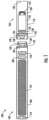
aerosol delivery device 100 according to the present disclosure is provided inFIG. 1 . As seen in the cut-away view illustrated therein, the aerosol delivery device can comprise acontrol body 102 and acartridge 104 that can be permanently or detachably aligned in a functioning relationship. Engagement of the control body and the cartridge can be press fit (as illustrated), threaded, interference fit, magnetic or the like. In particular, connection components, such as further described herein may be used. For example, the control body may include a coupler that is adapted to engage a connector on the cartridge. - In specific example implementations, one or both of the
control body 102 and thecartridge 104 may be referred to as being disposable or as being reusable. For example, the control body may have a replaceable battery or a rechargeable battery and thus may be combined with any type of recharging technology, including connection to a typical electrical outlet, connection to a car charger (i.e., cigarette lighter receptacle), and connection to a computer, such as through a universal serial bus (USB) cable. For example, an adaptor including a USB connector at one end and a control body connector at an opposing end is disclosed inU.S. Pat. App. Pub. No. 2014/0261495 to Novak et al. . Further, in some examples the cartridge may comprise a single-use cartridge, as disclosed inU.S. Pat. App. Pub. No. 2014/0060555 to Chang et al. . - As illustrated in
FIG. 1 , thecontrol body 102 can be formed of acontrol body shell 106 that can include a control component 108 (e.g., a microprocessor, individually or as part of a microcontroller), aflow sensor 110, abattery 112 and a light-emitting diode (LED) 114, and such components can be variably aligned. Further indicators (e.g., a haptic feedback component, an audio feedback component, or the like) can be included in addition to or as an alternative to the LED. Thecartridge 104 can be formed of acartridge shell 116 enclosing areservoir 118 that is in fluid communication with aliquid transport element 120 adapted to wick or otherwise transport an aerosol precursor composition stored in the reservoir housing to a heater 122 (sometimes referred to as a heating element). In some example, a valve may be positioned between the reservoir and heater, and configured to control an amount of aerosol precursor composition passed or delivered from the reservoir to the heater. - Various examples of materials configured to produce heat when electrical current is applied therethrough may be employed to form the
heater 122. The heater in these examples may be resistive heating element such as a wire coil. Example materials from which the wire coil may be formed include Kanthal (FeCrAl), Nichrome, Molybdenum disilicide (MoSi2), molybdenum silicide (MoSi), Molybdenum disilicide doped with Aluminum (Mo(Si,Al)2), graphite and graphite-based materials (e.g., carbon-based foams and yarns) and ceramics (e.g., positive or negative temperature coefficient ceramics). Example implementations of heaters or heating members useful in aerosol delivery devices according to the present disclosure are further described below, and can be incorporated into devices such as illustrated inFIG. 1 as described herein. - An
opening 124 may be present in the cartridge shell 116 (e.g., at the mouthend) to allow for egress of formed aerosol from thecartridge 104. Such components are representative of the components that may be present in a cartridge and are not intended to limit the scope of cartridge components that are encompassed by the present disclosure. - The
cartridge 104 also may include one or moreelectronic components 126, which may include an integrated circuit, a memory component, a sensor, or the like. The electronic components may be adapted to communicate with thecontrol component 108 and/or with an external device by wired or wireless means. The electronic components may be positioned anywhere within the cartridge or abase 128 thereof. - Although the
control component 108 and theflow sensor 110 are illustrated separately, it is understood that the control component and the flow sensor may be combined as an electronic circuit board with the air flow sensor attached directly thereto. Further, the electronic circuit board may be positioned horizontally relative the illustration ofFIG. 1 in that the electronic circuit board can be lengthwise parallel to the central axis of the control body. In some examples, the air flow sensor may comprise its own circuit board or other base element to which it can be attached. In some examples, a flexible circuit board may be utilized. A flexible circuit board may be configured into a variety of shapes, include substantially tubular shapes. In some examples, a flexible circuit board may be combined with, layered onto, or form part or all of a heater substrate as further described below. - The
control body 102 and thecartridge 104 may include components adapted to facilitate a fluid engagement therebetween. As illustrated inFIG. 1 , the control body can include acoupler 130 having acavity 132 therein. Thebase 128 of the cartridge can be adapted to engage the coupler and can include aprojection 134 adapted to fit within the cavity. Such engagement can facilitate a stable connection between the control body and the cartridge as well as establish an electrical connection between thebattery 112 andcontrol component 108 in the control body and theheater 122 in the cartridge. Further, thecontrol body shell 106 can include anair intake 136, which may be a notch in the shell where it connects to the coupler that allows for passage of ambient air around the coupler and into the shell where it then passes through thecavity 132 of the coupler and into the cartridge through theprojection 134. - A coupler and a base useful according to the present disclosure are described in
U.S. Pat. App. Pub. No. 2014/0261495 to Novak et al. . For example, thecoupler 130 as seen inFIG. 1 may define anouter periphery 138 configured to mate with aninner periphery 140 of thebase 128. In one example the inner periphery of the base may define a radius that is substantially equal to, or slightly greater than, a radius of the outer periphery of the coupler. Further, the coupler may define one ormore protrusions 142 at the outer periphery configured to engage one ormore recesses 144 defined at the inner periphery of the base. However, various other examples of structures, shapes and components may be employed to couple the base to the coupler. In some examples the connection between the base of thecartridge 104 and the coupler of thecontrol body 102 may be substantially permanent, whereas in other examples the connection therebetween may be releasable such that, for example, the control body may be reused with one or more additional cartridges that may be disposable and/or refillable. - The
aerosol delivery device 100 may be substantially rod-like or substantially tubular shaped or substantially cylindrically shaped in some examples. In other examples, further shapes and dimensions are encompassed - e.g., a rectangular or triangular cross-section, multifaceted shapes, or the like. - The
reservoir 118 illustrated inFIG. 1 can be a container or can be a fibrous reservoir, as presently described. For example, the reservoir can comprise one or more layers of nonwoven fibers substantially formed into the shape of a tube encircling the interior of thecartridge shell 116, in this example. An aerosol precursor composition can be retained in the reservoir. Liquid components, for example, can be sorptively retained by the reservoir. The reservoir can be in fluid connection with theliquid transport element 120. The liquid transport element can transport the aerosol precursor composition stored in the reservoir via capillary action to theheater 122 that is in the form of a metal wire coil in this example. As such, the heater is in a heating arrangement with the liquid transport element. Example implementations of reservoirs and transport elements useful in aerosol delivery devices according to the present disclosure are further described below, and such reservoirs and/or transport elements can be incorporated into devices such as illustrated inFIG. 1 as described herein. In particular, specific combinations of heating members and transport elements as further described below may be incorporated into devices such as illustrated inFIG. 1 as described herein. - In use, when a user draws on the
aerosol delivery device 100, airflow is detected by theflow sensor 110, and theheater 122 is activated to vaporize the components for the aerosol precursor composition. Drawing upon the mouthend of the aerosol delivery device causes ambient air to enter theair intake 136 and pass through thecavity 132 in thecoupler 130 and the central opening in theprojection 134 of thebase 128. In thecartridge 104, the drawn air combines with the formed vapor to form an aerosol. The aerosol is whisked, aspirated or otherwise drawn away from the heater and out theopening 124 in the mouthend of the aerosol delivery device. - The various components of an aerosol delivery device according to the present disclosure can be chosen from components described in the art and commercially available. Examples of batteries that can be used according to the disclosure are described in
U.S. Pat. App. Pub. No. 2010/0028766 to Peckerar et al. . - The
aerosol delivery device 100 can incorporate thesensor 110 or another sensor or detector for control of supply of electric power to theheater 122 when aerosol generation is desired (e.g., upon draw during use). As such, for example, there is provided a manner or method for turning off the power supply to the heater when the aerosol delivery device is not be drawn upon during use, and for turning on the power supply to actuate or trigger the generation of heat by the heater during draw. Additional representative types of sensing or detection mechanisms, structure and configuration thereof, components thereof, and general methods of operation thereof, are described inU.S. Pat. No. 5,261,424 to Sprinkel, Jr. ,U.S. Pat. No. 5,372,148 to McCafferty et al. , andPCT Pat. App. Pub. No. WO 2010/003480 to Flick . - The
aerosol delivery device 100 most preferably incorporates thecontrol component 108 or another control mechanism for controlling the amount of electric power to theheater 122 during draw. Representative types of electronic components, structure and configuration thereof, features thereof, and general methods of operation thereof, are described inU.S. Pat. No. 4,735,217 to Gerth et al .,U.S. Pat. No. 4,947,874 to Brooks et al. ,U.S. Pat. No. 5,372,148 to McCafferty et al. ,U.S. Pat. No. 6,040,560 to Fleischhauer et al. ,U.S. Pat. No. 7,040,314 to Nguyen et al. ,U.S. Pat. No. 8,205,622 to Pan ,U.S. Pat. App. Pub. No. 2009/0230117 to Fernando et al. ,U.S. Pat. App. Pub. No. 2014/0060554 to Collet et al. ,U.S. Pat. App. Pub. No. 2014/0270727 to Ampolini et al. , andU.S. Pat. App. Ser. No. 14/209,191 to Henry et al., filed March 13, 2014 - Representative types of substrates, reservoirs or other components for supporting the aerosol precursor are described in
U.S. Pat. No. 8,528,569 to Newton ,U.S. Pat. App. Pub. No. 2014/0261487 to Chapman et al. ,U.S. Pat. App. Ser. No. 14/011,992 to Davis et al., filed August 28, 2013 , andU.S. Pat. App. Ser. No. 14/170,838 to Bless et al., filed February 3, 2014 U.S. Pat. App. Pub. No. 2014/0209105 to Sears et al. - The aerosol precursor composition, also referred to as a vapor precursor composition, may comprise a variety of components including, by way of example, a polyhydric alcohol (e.g., glycerin, propylene glycol or a mixture thereof), nicotine, tobacco, tobacco extract and/or flavorants. Various components that may be included in the aerosol precursor composition are described in
U.S. Pat. No. 7,726,320 to Robinson et al. . Additional representative types of aerosol precursor compositions are set forth inU.S. Pat. No. 4,793,365 to Sensabaugh, Jr. et al. ,U.S. Pat. No. 5,101,839 to Jakob et al. ,U.S. Pat. No. 6,779,531 to Biggs et al. ,U.S. Pat. App. Pub. No. 2013/0008457 to Zheng et al ., and Chemical and Biological Studies on New Cigarette Prototypes that Heat Instead of Burn Tobacco, R. J. Reynolds Tobacco Company Monograph (1988). - Additional representative types of components that yield visual cues or indicators may be employed in the
aerosol delivery device 100, such as LEDs and related components, vibratory elements and the like. Examples of suitable LED components, and the configurations and uses thereof, are described inU.S. Pat. No. 5,154,192 to Sprinkel et al. ,U.S. Pat. No. 8,499,766 to Newton ,U.S. Pat. No. 8,539,959 to Scatterday , andU.S. Pat. App. Ser. No. 14/173,266 to Sears et al., filed February 5, 2014 - Yet other features, controls or components that can be incorporated into aerosol delivery devices of the present disclosure are described in
U.S. Pat. No. 5,967,148 to Harris et al. ,U.S. Pat. No. 5,934,289 to Watkins et al. ,U.S. Pat. No. 5,954,979 to Counts et al. ,U.S. Pat. No. 6,040,560 to Fleischhauer et al. ,U.S. Pat. No. 8,365,742 to Hon ,U.S. Pat. No. 8,402,976 to Fernando et al. ,U.S. Pat. App. Pub. No. 2010/0163063 to Fernando et al. ,U.S. Pat. App. Pub. No. 2013/0192623 to Tucker et al. ,U.S. Pat. App. Pub. No. 2013/0298905 to Leven et al. ,U.S. Pat. App. Pub. No. 2013/0180553 to Kim et al. ,U.S. Pat. App. Pub. No. 2014/0000638 to Sebastian et al. ,U.S. Pat. App. Pub. No. 2014/0261495 to Novak et al. , andU.S. Pat. App. Pub. No. 2014/0261408 to DePiano et al. . - Briefly returning to
FIG. 1 , in some examples, theflow sensor 110 may be implemented by a microelectromechanical systems-based (MEMS-based) sensor such as a MEMS microphone or MEMS pressure sensor within a housing of theaerosol delivery device 100, such as the housing of thecontrol body 102 orcartridge 104, or a single housing comprising control components and cartridge components. The MEMS-based sensor is configured to detect a pressure on the MEMS-based sensor caused by airflow through at least a portion of the housing, convert the pressure to an electrical signal, and output the electrical signal. The control component 108 (e.g., microprocessor) is configured to receive the electrical signal from the MEMS-based sensor, and control operation of at least one functional element of the aerosol delivery device based thereon. Such control can be achieved through implementation of one or more control algorithms utilizing program code instructions. Examples of suitable control may include the microprocessor being configured to control the operation of a heater, fluid-delivery member, sensory-feedback member or any combination thereof. - In some examples, the MEMS-based sensor may function similar to an on/off switch. In these examples, the electrical signal output by the MEMS-based sensor may be a bilevel signal in which the absence of or a zero level electrical signal may indicate an "off" state, and a positive electrical signal indicates an "on" state.
- In other examples, the MEMS-based sensor may be configured to convert the pressure to the electrical signal that varies with a corresponding variation in the pressure relative to an ambient pressure on the MEMS-based sensor. In these examples, the corresponding variation may be caused by variation in the airflow such as a variation in the rate of airflow.
-
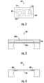
FIG. 2 illustrates a MEMS-basedsensor 200 that in some examples may correspond to a flow sensor such as theflow sensor 110 ofFIG. 1 . As shown, the MEMS-based sensor may include a (first) die 202 with amicromachined sensor 204. As also shown, the MEMS-based sensor may in some examples include another (second) die 206 wire bonded to the first die and including abias generator circuit 208 configured to bias the micromachined sensor with an input voltage. In these examples, in an instance in which an input voltage is applied to the micromachined sensor, the pressure causes movement of the diaphragm and thereby a change in an electrical property of the micromachined sensor. The change in the electrical property causes a change in an output voltage across the micromachined sensor. This output voltage may be output by the MEMS-based sensor as the electrical signal. Or in some examples, the MEMS-based sensor (e.g. on the second die) may include an appropriate analog-to-digital converter (ADC) or other circuitry configured to convert the output voltage to a digital representation, which the MEMS-based sensor may then output as the electrical signal. - In accordance with aspects of the present invention, the MEMS-based
sensor 200 is a MEMS microphone.FIG. 3 schematically illustrates amicromachined sensor 304 for a MEMS microphone, which in some examples may correspond to themicromachined sensor 204 ofFIG. 2 . As shown, the micromachined sensor of the MEMS microphone includes a micromachined, pressure-sensitive diaphragm 306a and abackplate 306b that form avariable capacitor 306. In these examples, in an instance in which an input voltage is applied to the variable capacitor, the pressure causes movement of the diaphragm and thereby a change in a capacitance of the variable capacitor. The change in capacitance causes a change in the output voltage across the variable capacitor. The MEMS microphone then outputs the output voltage or a digital representation of the output voltage as the electrical signal. - As will be appreciated, MEMS microphones are often utilized for audio applications in mobile telephones and hearing aids to capture audio for subsequent replication and output by speaker. These applications typically desire high fidelity of the audio output; and consequently, the MEMS microphone often includes a more complex bias generator circuit and additional circuitry such as various audio-grade filtering and amplification stages to more accurately capture and replicate audio. In the context of an aerosol delivery device, however, this additional circuitry may not be useful. In some examples, then, the MEMS microphone may include simplified versions of one or more of these components, or may not include them altogether. That is, the MEMS-based
sensor 200 including the dies 202, 206 may be packaged in anintegrated circuit package 210 with a more simplified bias generator circuit, less filtering and/or simpler, non-linear amplification, and may still be useful in many applications of an aerosol delivery device such as that described herein. According to an aspect of the present invention, the MEMS-based sensor is packaged in an integrated circuit package excluding audio-grade filtering and amplification stages. - In some examples, the MEMS-based
sensor 200 may be a MEMS pressure sensor.FIG. 4 schematically illustrates amicromachined sensor 404 for a MEMS pressure sensor, which in some examples may correspond to themicromachined sensor 204 ofFIG. 2 . As shown, the micromachined sensor of the MEMS pressure sensor may include a micromachined, pressure-sensitive diaphragm 406, and one or more piezoresistors 408 disposed on the diaphragm. In these examples, in an instance in which an input voltage is applied to the piezoresistor(s), the pressure causes movement of the diaphragm and thereby a change in a resistance of the piezoresistor(s). The change in resistance causes a change in the output voltage across the piezoresistor(s). The MEMS pressure sensor may then output the output voltage or a digital representation of the output voltage as the electrical signal. - Returning again to
FIG. 1 , the electrical signal output from theflow sensor 108, and more particularly in some examples the MEMS-based sensor (e.g., MEMS microphone, MEMS pressure sensor), can be used by one or more control elements of the aerosol delivery device to control the operation of the device. Such operation can encompass a variety of functional elements of the device, such as theheater 122, a fluid-delivery member, a sensory-feedback member and the like. - For example, the electrical signal from the flex/bend sensor can be used by a microprocessor to control opening and closing of a valve between the
reservoir 118 andheater 122. For example, as the draw on thedevice 100 increases and the electrical signal output by the sensor correspondingly changes, the opening of the valve can be increased to allow for a greater volume of aerosol precursor composition to pass from the reservoir to heater. In some examples in which a sensory feedback member is used (e.g., a LED or a vibratory element), an increased draw on the device can signal the microprocessor to cause a different lighting pattern by the LED or cause a different vibration pattern by the vibratory element. - In some examples, the electrical signal output from the
flow sensor 108 can be coupled with control electronics of thedevice 100 to alter the profile of a heating element in the device, such as theheater 122. In particular, the heating profile can be caused to change in real time relative to the airflow rate caused by the magnitude of the draw on the device. -
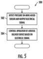
FIG. 5 illustrates various operations in amethod 500 of controlling operation of an aerosol delivery device including a MEMS-based sensor (e.g., MEMS microphone, MEMS pressure sensor). As shown atblock 502, the method may include detecting a pressure on the MEMS-based sensor caused by airflow through at least a portion of the housing, with the MEMS-based sensor converting the pressure to an electrical signal. In some examples, the MEMS-based sensor converting the pressure includes converting the pressure to the electrical signal that varies with a corresponding variation in the pressure relative to an ambient pressure on the MEMS-based sensor, the corresponding variation being caused by variation in the airflow such as a variation in the rate of the airflow. - As explained above with respect to
FIG. 3 , according to aspects of the present invention, the MEMS-based sensor is a MEMS microphone including amicromachined sensor 304 having a micromachined, pressure-sensitive diaphragm 306a and abackplate 306b that form avariable capacitor 306. In these examples, in an instance in which an input voltage is applied to the variable capacitor, the pressure causes movement of the diaphragm and thereby a change in a capacitance of the variable capacitor. The change in capacitance causes a change in an output voltage across the variable capacitor. And the MEMS microphone outputs the output voltage or a digital representation thereof as the electrical signal. - As explained above with respect to
FIG. 4 , in some examples the MEMS-based sensor may be a MEMS pressure sensor including amicromachined sensor 404 having a micromachined, pressure-sensitive diaphragm 406, and one or more piezoresistors 408 disposed on the diaphragm. In these examples, in an instance in which an input voltage is applied to the piezoresistor(s), the pressure causes movement of the diaphragm and thereby a change in a resistance of the piezoresistor(s). The change in resistance causes a change in an output voltage across the piezoresistor(s). And the MEMS pressure sensor outputs the output voltage or a digital representation thereof as the electrical signal. - Regardless of the particular construction of the MEMS-based sensor, the method may include controlling operation of at least one functional element of the aerosol delivery device based on the electrical signal from the MEMS-based sensor, as shown at
block 504. This may include, for example, controlling the operation of a heater, fluid-delivery member, sensory-feedback member or any combination thereof. - As a more particular example use of a variable electrical signal from the MEMS-based sensor, airflow rate through an aerosol delivery device can be detected with the MEMS-based sensor upon draw on the device by a user, and such airflow rate can be continuously detected for the duration of the draw. The MEMS-based sensor can output a signal that can vary based upon the airflow rate. The variable signal output from the MEMS-based sensor can be input by the microprocessor into a control algorithm to make the defined calculations based thereon and determine the requisite parameters for one or more properties of electrical current supplied to the heater relative to the output signal from the MEMS-based sensor. The microprocessor then directs electrical current flow to the heater with the requisite parameters to define heater function based upon the real time airflow rate through the device. In this manner, heater function can be continuously controlled and altered as necessary relative to the airflow rate through the device.
- The foregoing description of use of the article can be applied to the various example implementations described herein through minor modifications, which can be apparent to the person of skill in the art in light of the further disclosure provided herein. The above description of use, however, is not intended to limit the use of the article but is provided to comply with all necessary requirements of disclosure of the present disclosure. Any of the elements shown in the article illustrated in
FIG. 1 or as otherwise described above may be included in an aerosol delivery device according to the present disclosure.
Claims (9)
- An aerosol delivery device (100) comprising:a housing (102, 104);a microelectromechanical systems-based (MEMS-based) sensor (110, 200) within the housing and configured to detect a pressure on the MEMS-based sensor (110, 200) caused by airflow through at least a portion of the housing, the MEMS-based sensor (110, 200) being configured to convert the pressure to an electrical signal, and output the electrical signal; anda microprocessor (108) configured to receive the electrical signal from the MEMS-based sensor (110, 200), and control operation of at least one functional element of the aerosol delivery device (100) based thereon,wherein the MEMS-based sensor is a MEMS microphone including a die (202, 304) with a micromachined, pressure-sensitive diaphragm (306a) and a backplate (306b) that form a variable capacitor (306), the MEMS-based sensor packaged in an integrated circuit package (210) excluding audio-grade filtering and amplification stages, andwherein in an instance in which an input voltage is applied to the variable capacitor, the pressure causes movement of the diaphragm (306a) and thereby a change in a capacitance of the variable capacitor (306), the change in capacitance causing a change in an output voltage across the variable capacitor (306), the output voltage or a digital representation thereof being output by the MEMS microphone as the electrical signal.
- The aerosol delivery device (100) of Claim 1, wherein the MEMS-based sensor (110, 200) being configured to convert the pressure includes being configured to convert the pressure to the electrical signal that varies with a corresponding variation in the pressure relative to an ambient pressure on the MEMS-based sensor (110, 200), the corresponding variation being caused by variation in the airflow.
- The aerosol delivery device (100) of Claim 2, wherein the corresponding variation in the pressure is caused by variation in a rate of the airflow.
- The aerosol delivery device (100) of any one of Claims 1 to 3, wherein the MEMS microphone further comprises another die (206) wire bonded to the die (202) and including a bias generator circuit configured to bias the variable capacitor with the input voltage.
- The aerosol delivery device (100) of any one of Claims 1 to 4, wherein the microprocessor (108) being configured to control the operation of at least one functional element includes being configured to control the operation of a heater (122), fluid-delivery member, sensory-feedback member or any combination thereof.
- A method (500) for controlling operation of an aerosol delivery device (100) including a microelectromechanical systems-based (MEMS-based) sensor (110, 200) within a housing thereof, the method comprising:detecting an pressure on the MEMS-based sensor (110, 200) caused by airflow through at least a portion of the housing, the MEMS-based sensor (110, 200) converting the pressure to an electrical signal (502); andcontrolling operation of at least one functional element of the aerosol delivery device (100) based on the electrical signal (504),wherein the MEMS-based sensor (110, 200) is a MEMS microphone including a die (202) with a micromachined, pressure-sensitive diaphragm (306a) and a backplate (306b) that form a variable capacitor (306), the MEMS-based sensor (110, 200) packaged in an integrated circuit package (210) excluding audio-grade filtering and amplification stages, andwherein in an instance in which an input voltage is applied to the variable capacitor, the pressure causes movement of the diaphragm (306a) and thereby a change in a capacitance of the variable capacitor (306), the change in capacitance causing a change in an output voltage across the variable capacitor (306), the MEMS microphone outputting the output voltage or a digital representation thereof as the electrical signal.
- The method of Claim 6, wherein the MEMS-based sensor (110, 200) converting the pressure includes converting the pressure to the electrical signal that varies with a corresponding variation in the pressure relative to an ambient pressure on the MEMS-based sensor (110, 200), the corresponding variation being caused by variation in the airflow.
- The method of Claim 7, wherein the corresponding variation in the pressure is caused by variation in a rate of the airflow.
- The method of any one of Claims 6 to 8, wherein controlling the operation of at least one functional element includes controlling the operation of a heater (122), fluid-delivery member, sensory-feedback member or any combination thereof.
Priority Applications (1)
| Application Number | Priority Date | Filing Date | Title |
|---|---|---|---|
| EP25166173.2A EP4570096A1 (en) | 2014-11-12 | 2015-11-11 | Mems-based sensor for an aerosol delivery device |
Applications Claiming Priority (4)
| Application Number | Priority Date | Filing Date | Title |
|---|---|---|---|
| US14/539,215 US11051554B2 (en) | 2014-11-12 | 2014-11-12 | MEMS-based sensor for an aerosol delivery device |
| PCT/US2015/060099 WO2016077428A1 (en) | 2014-11-12 | 2015-11-11 | Mems-based sensor for an aerosol delivery device |
| EP18188661.5A EP3424352B1 (en) | 2014-11-12 | 2015-11-11 | Mems-based sensor for an aerosol delivery device |
| EP15797773.7A EP3217816B2 (en) | 2014-11-12 | 2015-11-11 | Mems-based sensor for an aerosol delivery device |
Related Parent Applications (4)
| Application Number | Title | Priority Date | Filing Date |
|---|---|---|---|
| EP15797773.7A Division EP3217816B2 (en) | 2014-11-12 | 2015-11-11 | Mems-based sensor for an aerosol delivery device |
| EP15797773.7A Division-Into EP3217816B2 (en) | 2014-11-12 | 2015-11-11 | Mems-based sensor for an aerosol delivery device |
| EP18188661.5A Division-Into EP3424352B1 (en) | 2014-11-12 | 2015-11-11 | Mems-based sensor for an aerosol delivery device |
| EP18188661.5A Division EP3424352B1 (en) | 2014-11-12 | 2015-11-11 | Mems-based sensor for an aerosol delivery device |
Related Child Applications (1)
| Application Number | Title | Priority Date | Filing Date |
|---|---|---|---|
| EP25166173.2A Division EP4570096A1 (en) | 2014-11-12 | 2015-11-11 | Mems-based sensor for an aerosol delivery device |
Publications (2)
| Publication Number | Publication Date |
|---|---|
| EP3861874A1 EP3861874A1 (en) | 2021-08-11 |
| EP3861874B1 true EP3861874B1 (en) | 2025-03-26 |
Family
ID=54608976
Family Applications (4)
| Application Number | Title | Priority Date | Filing Date |
|---|---|---|---|
| EP18188661.5A Revoked EP3424352B1 (en) | 2014-11-12 | 2015-11-11 | Mems-based sensor for an aerosol delivery device |
| EP15797773.7A Active EP3217816B2 (en) | 2014-11-12 | 2015-11-11 | Mems-based sensor for an aerosol delivery device |
| EP25166173.2A Pending EP4570096A1 (en) | 2014-11-12 | 2015-11-11 | Mems-based sensor for an aerosol delivery device |
| EP21162768.2A Active EP3861874B1 (en) | 2014-11-12 | 2015-11-11 | Mems-based sensor for an aerosol delivery device |
Family Applications Before (3)
| Application Number | Title | Priority Date | Filing Date |
|---|---|---|---|
| EP18188661.5A Revoked EP3424352B1 (en) | 2014-11-12 | 2015-11-11 | Mems-based sensor for an aerosol delivery device |
| EP15797773.7A Active EP3217816B2 (en) | 2014-11-12 | 2015-11-11 | Mems-based sensor for an aerosol delivery device |
| EP25166173.2A Pending EP4570096A1 (en) | 2014-11-12 | 2015-11-11 | Mems-based sensor for an aerosol delivery device |
Country Status (9)
| Country | Link |
|---|---|
| US (4) | US11051554B2 (en) |
| EP (4) | EP3424352B1 (en) |
| JP (3) | JP2017535265A (en) |
| CN (3) | CN116076805A (en) |
| ES (2) | ES2879235T3 (en) |
| HK (1) | HK1243884B (en) |
| HU (2) | HUE042085T2 (en) |
| PL (3) | PL3424352T3 (en) |
| WO (1) | WO2016077428A1 (en) |
Families Citing this family (75)
| Publication number | Priority date | Publication date | Assignee | Title |
|---|---|---|---|---|
| US20160345631A1 (en) | 2005-07-19 | 2016-12-01 | James Monsees | Portable devices for generating an inhalable vapor |
| US11253661B2 (en) | 2012-06-25 | 2022-02-22 | Gecko Health Innovations, Inc. | Devices, systems, and methods for adherence monitoring and patient interaction |
| US10279934B2 (en) | 2013-03-15 | 2019-05-07 | Juul Labs, Inc. | Fillable vaporizer cartridge and method of filling |
| EA036564B1 (en) | 2013-08-28 | 2020-11-24 | Джеко Хелт Инновейшнз, Инк. | Devices, systems, and methods for adherence monitoring and devices, systems, and methods for monitoring use of consumable dispensers |
| US20160366947A1 (en) | 2013-12-23 | 2016-12-22 | James Monsees | Vaporizer apparatus |
| USD825102S1 (en) | 2016-07-28 | 2018-08-07 | Juul Labs, Inc. | Vaporizer device with cartridge |
| US10058129B2 (en) | 2013-12-23 | 2018-08-28 | Juul Labs, Inc. | Vaporization device systems and methods |
| USD842536S1 (en) | 2016-07-28 | 2019-03-05 | Juul Labs, Inc. | Vaporizer cartridge |
| US10159282B2 (en) | 2013-12-23 | 2018-12-25 | Juul Labs, Inc. | Cartridge for use with a vaporizer device |
| EP3928646B1 (en) | 2013-12-23 | 2025-03-26 | Juul Labs International Inc. | Vaporization device systems |
| US10076139B2 (en) | 2013-12-23 | 2018-09-18 | Juul Labs, Inc. | Vaporizer apparatus |
| US12279646B2 (en) | 2014-02-06 | 2025-04-22 | Juul Labs, Inc. | Cartridge of vaporization device systems having unequal transverse cartridge dimensions |
| TW201620569A (en) | 2014-08-28 | 2016-06-16 | 微劑量醫療公司 | Compliance monitoring module for an inhaler |
| TW201617102A (en) | 2014-08-28 | 2016-05-16 | 微劑量醫療公司 | Compliance monitoring module for respiratory drive inhalers |
| JP6799529B2 (en) | 2014-08-28 | 2020-12-16 | マイクロドース セラピューテクス,インコーポレイテッド | Tidal dry powder inhaler with small pressure sensor activation |
| RU2017115353A (en) | 2014-10-02 | 2018-11-02 | Диджиретс, Инк. | ELECTRONIC CIGARETTE WITH DISPOSABLE CAPACITY, METHOD OF MANUFACTURE AND METHOD OF APPLICATION |
| GB201420039D0 (en) | 2014-11-11 | 2014-12-24 | Teva Uk Ltd | System for training a user in administering a medicament |
| US11051554B2 (en) | 2014-11-12 | 2021-07-06 | Rai Strategic Holdings, Inc. | MEMS-based sensor for an aerosol delivery device |
| US10058661B2 (en) | 2014-12-04 | 2018-08-28 | Norton (Waterford) Limited | Inhalation monitoring system and method |
| RU2709926C2 (en) | 2014-12-05 | 2019-12-23 | Джуул Лэбз, Инк. | Calibrated dose control |
| GB201501429D0 (en) * | 2015-01-28 | 2015-03-11 | British American Tobacco Co | Apparatus for heating aerosol generating material |
| CN104824848B (en) * | 2015-03-10 | 2018-04-03 | 深圳麦克韦尔股份有限公司 | Electronic cigarette |
| US11000069B2 (en) * | 2015-05-15 | 2021-05-11 | Rai Strategic Holdings, Inc. | Aerosol delivery device and methods of formation thereof |
| US10736356B2 (en) * | 2015-06-25 | 2020-08-11 | Altria Client Services Llc | Electronic vaping device having pressure sensor |
| CN104983073A (en) * | 2015-07-07 | 2015-10-21 | 深圳市赛尔美电子科技有限公司 | Cigarette distillation device |
| US10085486B2 (en) * | 2015-09-24 | 2018-10-02 | Lunatech, Llc | Electronic vapor device with film assembly |
| US20170112194A1 (en) * | 2015-10-21 | 2017-04-27 | Rai Strategic Holdings, Inc. | Rechargeable lithium-ion capacitor for an aerosol delivery device |
| SG11201806793TA (en) | 2016-02-11 | 2018-09-27 | Juul Labs Inc | Fillable vaporizer cartridge and method of filling |
| EP3419443A4 (en) | 2016-02-11 | 2019-11-20 | Juul Labs, Inc. | CARTRIDGES SECURELY FIXED FOR VAPORIZATION DEVICES |
| SG11201807028YA (en) | 2016-02-25 | 2018-09-27 | Juul Labs Inc | Vaporization device control systems and methods |
| US10405582B2 (en) | 2016-03-10 | 2019-09-10 | Pax Labs, Inc. | Vaporization device with lip sensing |
| US10292427B2 (en) * | 2016-04-25 | 2019-05-21 | Lunatech, Llc | Electronic vaporizing device having lighting control functionality |
| US11038360B2 (en) * | 2016-05-18 | 2021-06-15 | Gsw Creative Corporation | Vaporization device, method of using the device, a charging case, a kit, and a vibration assembly |
| USD849996S1 (en) | 2016-06-16 | 2019-05-28 | Pax Labs, Inc. | Vaporizer cartridge |
| USD836541S1 (en) | 2016-06-23 | 2018-12-25 | Pax Labs, Inc. | Charging device |
| USD851830S1 (en) | 2016-06-23 | 2019-06-18 | Pax Labs, Inc. | Combined vaporizer tamp and pick tool |
| GB201616036D0 (en) | 2016-09-21 | 2016-11-02 | Nicoventures Holdings Ltd | Device with liquid flow restriction |
| CN110167619B (en) | 2016-11-18 | 2021-11-26 | 诺顿(沃特福特)有限公司 | Drug delivery device with electronic components |
| US10524509B2 (en) * | 2016-11-18 | 2020-01-07 | Rai Strategic Holdings, Inc. | Pressure sensing for an aerosol delivery device |
| US11000653B2 (en) | 2016-11-18 | 2021-05-11 | Norton (Waterford) Limited | Inhaler |
| GB201700812D0 (en) | 2017-01-17 | 2017-03-01 | British American Tobacco Investments Ltd | Apparatus for heating smokable material |
| WO2018217926A1 (en) | 2017-05-24 | 2018-11-29 | Vmr Products Llc | Flavor disk |
| US12478109B2 (en) | 2017-09-07 | 2025-11-25 | Philip Morris Products S.A. | MEMS sound generation for aerosol-generating devices and related user interfaces and methods |
| EP3681319B1 (en) | 2017-09-07 | 2024-03-13 | Philip Morris Products S.A. | Aerosol-generating devices for use with different substrates and related user interfaces and methods |
| USD887632S1 (en) | 2017-09-14 | 2020-06-16 | Pax Labs, Inc. | Vaporizer cartridge |
| US11039645B2 (en) | 2017-09-19 | 2021-06-22 | Rai Strategic Holdings, Inc. | Differential pressure sensor for an aerosol delivery device |
| RU2764604C2 (en) * | 2017-10-05 | 2022-01-18 | Филип Моррис Продактс С.А. | Electrically controlled aerosol-generating apparatus with continuous power supply adjustment |
| IL263217B (en) * | 2017-11-24 | 2022-06-01 | Juul Labs Inc | Emission sensing and power circuit for vaporizers |
| US11035704B2 (en) | 2017-12-29 | 2021-06-15 | Altria Client Services Llc | Sensor apparatus |
| EP3539397B1 (en) * | 2018-06-20 | 2021-10-20 | Shenzhen First Union Technology Co., Ltd. | Electronic cigarette and method for its operation |
| WO2020057381A1 (en) * | 2018-09-17 | 2020-03-26 | 常州市派腾电子技术服务有限公司 | Electronic cigarette control method and device, assembly method, electronic cigarette, and computer storage medium |
| WO2020090375A1 (en) | 2018-10-30 | 2020-05-07 | 日本たばこ産業株式会社 | Power supply unit of aerosol generation device, control method of power supply unit of aerosol generation device, and program for power supply unit of aerosol generation device |
| WO2020090374A1 (en) | 2018-10-30 | 2020-05-07 | 日本たばこ産業株式会社 | Power supply unit of aerosol generation device, control method of power supply unit of aerosol generation device, and program for power supply unit of aerosol generation device |
| US11592793B2 (en) | 2018-11-19 | 2023-02-28 | Rai Strategic Holdings, Inc. | Power control for an aerosol delivery device |
| US11614720B2 (en) | 2018-11-19 | 2023-03-28 | Rai Strategic Holdings, Inc. | Temperature control in an aerosol delivery device |
| US11690405B2 (en) | 2019-04-25 | 2023-07-04 | Rai Strategic Holdings, Inc. | Artificial intelligence in an aerosol delivery device |
| JP7664181B2 (en) | 2019-04-30 | 2025-04-17 | ノートン (ウォーターフォード) リミテッド | Inhaler System |
| US11419995B2 (en) | 2019-04-30 | 2022-08-23 | Norton (Waterford) Limited | Inhaler system |
| GB201906279D0 (en) * | 2019-05-03 | 2019-06-19 | Nicoventures Trading Ltd | Electronic aerosol provision system |
| EP4036921A1 (en) | 2019-05-17 | 2022-08-03 | Norton (Waterford) Limited | Drug delivery device with electronics |
| JP7439141B2 (en) * | 2019-06-17 | 2024-02-27 | フラウンホファー ゲセルシャフト ツール フェールデルンク ダー アンゲヴァンテン フォルシュンク エー.ファオ. | Sensor module and method for determining aerosol dose rate |
| CA192725S (en) | 2019-08-01 | 2022-04-07 | Nicoventures Trading Ltd | Aerosol generating device |
| IT201900019169A1 (en) * | 2019-10-17 | 2021-04-17 | St Microelectronics Srl | WATERPROOF SWITCH THAT CAN BE OPERATED BY A FLUID SUCH AS AIR AND USED IN PARTICULAR FOR THE ACTIVATION OF AN INHALER DEVICE, SUCH AS AN ELECTRONIC CIGARETTE |
| CN111035071A (en) * | 2020-01-10 | 2020-04-21 | 新鼎电子(深圳)有限公司 | Electronic cigarette capable of automatically adjusting smoke amount |
| WO2021156365A1 (en) | 2020-02-06 | 2021-08-12 | Philip Morris Products S.A. | Electrically operated aerosol-generating device with means for detecting an airflow in the device |
| CN112075672A (en) * | 2020-09-30 | 2020-12-15 | 苏州敏芯微电子技术股份有限公司 | Sensing device and electronic cigarette |
| USD985187S1 (en) | 2021-01-08 | 2023-05-02 | Nicoventures Trading Limited | Aerosol generator |
| USD984730S1 (en) | 2021-07-08 | 2023-04-25 | Nicoventures Trading Limited | Aerosol generator |
| US12143779B2 (en) * | 2021-07-22 | 2024-11-12 | Apple Inc. | Airflow sensors for speakers |
| KR102696395B1 (en) * | 2021-08-27 | 2024-08-20 | 주식회사 케이티앤지 | Aerosol generating apparatus and controling method thereof |
| US20240053179A1 (en) * | 2022-08-12 | 2024-02-15 | Gmems Tech Shenzhen Limited | Micromachined capacitive flow sensor, packaged flow sensor product comprising the same, and method thereof |
| CN115486563A (en) * | 2022-08-31 | 2022-12-20 | 深圳麦时科技有限公司 | Aerosol generating device |
| EP4642271A1 (en) * | 2022-12-30 | 2025-11-05 | KT&G Corporation | Aerosol generating device |
| US20240306729A1 (en) * | 2023-03-14 | 2024-09-19 | Rai Strategic Holdings, Inc. | Multiple-temperature monitoring for an aerosol provision system |
| CN118452543A (en) * | 2023-12-27 | 2024-08-09 | 安徽奥飞声学科技有限公司 | Piezoelectric MEMS pressure sensor and electronic cigarette including the same |
Citations (22)
| Publication number | Priority date | Publication date | Assignee | Title |
|---|---|---|---|---|
| WO1998029711A1 (en) | 1996-12-31 | 1998-07-09 | Motorola Semiconductors S.A. | Sensor arrangement and method of biasing a sensor |
| US7111518B1 (en) | 2003-09-19 | 2006-09-26 | Silicon Microstructures, Inc. | Extremely low cost pressure sensor realized using deep reactive ion etching |
| US20070044793A1 (en) | 2005-08-26 | 2007-03-01 | North Carolina State University | Inhaler system for targeted maximum drug-aerosol delivery |
| WO2009127401A1 (en) | 2008-04-17 | 2009-10-22 | Philip Morris Products S.A. | An electrically heated smoking system |
| US20100163063A1 (en) | 2008-12-24 | 2010-07-01 | Philip Morris Usa Inc. | Article Including Identification Information for Use in an Electrically Heated Smoking System |
| WO2011033296A1 (en) | 2009-09-15 | 2011-03-24 | Shire Llc | Prodrugs of guanfacine |
| WO2011063970A1 (en) | 2009-11-27 | 2011-06-03 | Philip Morris Products S.A. | An electrically heated smoking system with internal or external heater |
| EP2157873B1 (en) | 2007-05-11 | 2011-07-06 | Smokefree Innotec Corporation | Smoking device, charging means and method of using it |
| US20110265806A1 (en) | 2010-04-30 | 2011-11-03 | Ramon Alarcon | Electronic smoking device |
| US20120186594A1 (en) | 2009-09-18 | 2012-07-26 | Minilogic Device Corporation Ltd. | Electronic smoke |
| CN102793276A (en) | 2012-08-03 | 2012-11-28 | 胡朝群 | Electronic cigarette chip and electronic cigarette |
| WO2013060781A1 (en) | 2011-10-27 | 2013-05-02 | Philip Morris Products S.A. | Aerosol generating system with improved aerosol production |
| WO2013060784A2 (en) | 2011-10-27 | 2013-05-02 | Philip Morris Products S.A. | An electrically operated aerosol generating system having aerosol production control |
| CN103251133A (en) | 2013-05-20 | 2013-08-21 | 西安拓尔微电子有限责任公司 | Electronic cigarette controlling chip with locking function |
| US20130298905A1 (en) * | 2012-03-12 | 2013-11-14 | UpToke, LLC | Electronic vaporizing device and methods for use |
| WO2014054035A1 (en) | 2012-10-05 | 2014-04-10 | Smart Chip Microelectronic Co. Limited | Electronic smoke apparatus |
| GB2507104A (en) | 2012-10-19 | 2014-04-23 | Nicoventures Holdings Ltd | Electronic inhalation device |
| US20140175572A1 (en) | 2012-12-20 | 2014-06-26 | Industrial Technology Research Institute | Mems device with multiple electrodes and fabricating method thereof |
| WO2014107798A1 (en) | 2013-01-14 | 2014-07-17 | University Health Network | Mask and method for breathing disorder identification, characterization and/or diagnosis |
| WO2014110119A1 (en) | 2013-01-08 | 2014-07-17 | L. Perrigo Company | Electronic cigarette |
| JP2014206514A (en) | 2013-04-16 | 2014-10-30 | パナソニック株式会社 | Pressure sensor |
| WO2016030521A1 (en) | 2014-08-28 | 2016-03-03 | Norton (Waterford) Limited | Compliance-assisting module for an inhaler |
Family Cites Families (185)
| Publication number | Priority date | Publication date | Assignee | Title |
|---|---|---|---|---|
| US2057353A (en) | 1936-10-13 | Vaporizing unit fob therapeutic | ||
| US1771366A (en) | 1926-10-30 | 1930-07-22 | R W Cramer & Company Inc | Medicating apparatus |
| US2104266A (en) | 1935-09-23 | 1938-01-04 | William J Mccormick | Means for the production and inhalation of tobacco fumes |
| US3200819A (en) | 1963-04-17 | 1965-08-17 | Herbert A Gilbert | Smokeless non-tobacco cigarette |
| US4284089A (en) | 1978-10-02 | 1981-08-18 | Ray Jon P | Simulated smoking device |
| US4303083A (en) | 1980-10-10 | 1981-12-01 | Burruss Jr Robert P | Device for evaporation and inhalation of volatile compounds and medications |
| US4793365A (en) | 1984-09-14 | 1988-12-27 | R. J. Reynolds Tobacco Company | Smoking article |
| SE8405479D0 (en) | 1984-11-01 | 1984-11-01 | Nilsson Sven Erik | WANT TO ADMINISTER VOCABULARY, PHYSIOLOGY, ACTIVE SUBJECTS AND DEVICE FOR THIS |
| US4735217A (en) | 1986-08-21 | 1988-04-05 | The Procter & Gamble Company | Dosing device to provide vaporized medicament to the lungs as a fine aerosol |
| GB8713645D0 (en) | 1987-06-11 | 1987-07-15 | Imp Tobacco Ltd | Smoking device |
| US5019122A (en) | 1987-08-21 | 1991-05-28 | R. J. Reynolds Tobacco Company | Smoking article with an enclosed heat conductive capsule containing an aerosol forming substance |
| US4922901A (en) | 1988-09-08 | 1990-05-08 | R. J. Reynolds Tobacco Company | Drug delivery articles utilizing electrical energy |
| US4947875A (en) | 1988-09-08 | 1990-08-14 | R. J. Reynolds Tobacco Company | Flavor delivery articles utilizing electrical energy |
| US4947874A (en) | 1988-09-08 | 1990-08-14 | R. J. Reynolds Tobacco Company | Smoking articles utilizing electrical energy |
| US4986286A (en) | 1989-05-02 | 1991-01-22 | R. J. Reynolds Tobacco Company | Tobacco treatment process |
| US4945931A (en) | 1989-07-14 | 1990-08-07 | Brown & Williamson Tobacco Corporation | Simulated smoking device |
| US5154192A (en) | 1989-07-18 | 1992-10-13 | Philip Morris Incorporated | Thermal indicators for smoking articles and the method of application of the thermal indicators to the smoking article |
| US5101839A (en) | 1990-08-15 | 1992-04-07 | R. J. Reynolds Tobacco Company | Cigarette and smokable filler material therefor |
| US5144962A (en) | 1989-12-01 | 1992-09-08 | Philip Morris Incorporated | Flavor-delivery article |
| US5093894A (en) | 1989-12-01 | 1992-03-03 | Philip Morris Incorporated | Electrically-powered linear heating element |
| US5060671A (en) | 1989-12-01 | 1991-10-29 | Philip Morris Incorporated | Flavor generating article |
| US5408574A (en) | 1989-12-01 | 1995-04-18 | Philip Morris Incorporated | Flat ceramic heater having discrete heating zones |
| US5042510A (en) | 1990-01-08 | 1991-08-27 | Curtiss Philip F | Simulated cigarette |
| US5530225A (en) | 1991-03-11 | 1996-06-25 | Philip Morris Incorporated | Interdigitated cylindrical heater for use in an electrical smoking article |
| US5249586A (en) | 1991-03-11 | 1993-10-05 | Philip Morris Incorporated | Electrical smoking |
| US5505214A (en) | 1991-03-11 | 1996-04-09 | Philip Morris Incorporated | Electrical smoking article and method for making same |
| US5726421A (en) | 1991-03-11 | 1998-03-10 | Philip Morris Incorporated | Protective and cigarette ejection system for an electrical smoking system |
| US5261424A (en) | 1991-05-31 | 1993-11-16 | Philip Morris Incorporated | Control device for flavor-generating article |
| CA2466075C (en) | 1992-03-25 | 2007-05-01 | Japan Tobacco, Inc. | Components for smoking articles and process for making same |
| US5353813A (en) | 1992-08-19 | 1994-10-11 | Philip Morris Incorporated | Reinforced carbon heater with discrete heating zones |
| US5322075A (en) | 1992-09-10 | 1994-06-21 | Philip Morris Incorporated | Heater for an electric flavor-generating article |
| US5498850A (en) | 1992-09-11 | 1996-03-12 | Philip Morris Incorporated | Semiconductor electrical heater and method for making same |
| US5369723A (en) | 1992-09-11 | 1994-11-29 | Philip Morris Incorporated | Tobacco flavor unit for electrical smoking article comprising fibrous mat |
| US5441060A (en) | 1993-02-08 | 1995-08-15 | Duke University | Dry powder delivery system |
| US5372148A (en) | 1993-02-24 | 1994-12-13 | Philip Morris Incorporated | Method and apparatus for controlling the supply of energy to a heating load in a smoking article |
| US5468936A (en) | 1993-03-23 | 1995-11-21 | Philip Morris Incorporated | Heater having a multiple-layer ceramic substrate and method of fabrication |
| US5666977A (en) | 1993-06-10 | 1997-09-16 | Philip Morris Incorporated | Electrical smoking article using liquid tobacco flavor medium delivery system |
| DE69430196T2 (en) | 1993-06-29 | 2002-10-31 | Ponwell Enterprises Ltd., Hongkong | DONOR |
| US5388574A (en) | 1993-07-29 | 1995-02-14 | Ingebrethsen; Bradley J. | Aerosol delivery article |
| CH686872A5 (en) | 1993-08-09 | 1996-07-31 | Disetronic Ag | Medical Inhalationsgeraet. |
| DE4328243C1 (en) | 1993-08-19 | 1995-03-09 | Sven Mielordt | Smoke or inhalation device |
| IE72523B1 (en) | 1994-03-10 | 1997-04-23 | Elan Med Tech | Nicotine oral delivery device |
| US5649554A (en) | 1995-10-16 | 1997-07-22 | Philip Morris Incorporated | Electrical lighter with a rotatable tobacco supply |
| US5564442A (en) | 1995-11-22 | 1996-10-15 | Angus Collingwood MacDonald | Battery powered nicotine vaporizer |
| JP3325028B2 (en) | 1996-06-17 | 2002-09-17 | 日本たばこ産業株式会社 | Flavor producing products |
| CN1113621C (en) | 1996-06-17 | 2003-07-09 | 日本烟业产业株式会社 | Flavor generating product and flavor generating tool |
| US6089857A (en) | 1996-06-21 | 2000-07-18 | Japan Tobacco, Inc. | Heater for generating flavor and flavor generation appliance |
| US5934289A (en) | 1996-10-22 | 1999-08-10 | Philip Morris Incorporated | Electronic smoking system |
| US6040560A (en) | 1996-10-22 | 2000-03-21 | Philip Morris Incorporated | Power controller and method of operating an electrical smoking system |
| US5878752A (en) | 1996-11-25 | 1999-03-09 | Philip Morris Incorporated | Method and apparatus for using, cleaning, and maintaining electrical heat sources and lighters useful in smoking systems and other apparatuses |
| US5865186A (en) | 1997-05-21 | 1999-02-02 | Volsey, Ii; Jack J | Simulated heated cigarette |
| GB9712815D0 (en) | 1997-06-19 | 1997-08-20 | British American Tobacco Co | Smoking article and smoking material therefor |
| KR100289448B1 (en) | 1997-07-23 | 2001-05-02 | 미즈노 마사루 | Flavor generator |
| US5954979A (en) | 1997-10-16 | 1999-09-21 | Philip Morris Incorporated | Heater fixture of an electrical smoking system |
| US5967148A (en) | 1997-10-16 | 1999-10-19 | Philip Morris Incorporated | Lighter actuation system |
| DE69834210T2 (en) | 1997-11-19 | 2007-01-04 | Microflow Engineering S.A. | Sprayer for an inhaler |
| CN1044314C (en) | 1997-12-01 | 1999-07-28 | 蒲邯名 | Healthy cigarette |
| US6164287A (en) | 1998-06-10 | 2000-12-26 | R. J. Reynolds Tobacco Company | Smoking method |
| US6095153A (en) | 1998-06-19 | 2000-08-01 | Kessler; Stephen B. | Vaporization of volatile materials |
| US6234167B1 (en) | 1998-10-14 | 2001-05-22 | Chrysalis Technologies, Incorporated | Aerosol generator and methods of making and using an aerosol generator |
| US6053176A (en) | 1999-02-23 | 2000-04-25 | Philip Morris Incorporated | Heater and method for efficiently generating an aerosol from an indexing substrate |
| US6196218B1 (en) | 1999-02-24 | 2001-03-06 | Ponwell Enterprises Ltd | Piezo inhaler |
| CA2385324C (en) | 1999-09-22 | 2008-03-25 | Miodrag Oljaca | Liquid atomization methods and devices |
| AU1620401A (en) | 1999-11-19 | 2001-05-30 | Perkin Elmer Instruments Llc | Hybrid film type sensor |
| PT1265504E (en) | 2000-03-23 | 2009-09-04 | Pmpi Llc | Electrical smoking system and method |
| US7559324B2 (en) | 2000-06-21 | 2009-07-14 | Fisher & Paykel Healthcare Limited | Conduit with heated wick |
| ES2230196T3 (en) | 2001-04-05 | 2005-05-01 | C.T.R., Consultoria, Tecnica E Representacoies Lda | DEVICE FOR VAPORZATION OF VOLATILE SUBSTANCES, ESPECIALLY INSECTICIDES AND / OR AROMATIC SUBSTANCES. |
| EP1468618B1 (en) | 2001-12-28 | 2008-07-09 | Japan Tobacco Inc. | Smoking implement |
| US6772756B2 (en) | 2002-02-09 | 2004-08-10 | Advanced Inhalation Revolutions Inc. | Method and system for vaporization of a substance |
| US6615840B1 (en) | 2002-02-15 | 2003-09-09 | Philip Morris Incorporated | Electrical smoking system and method |
| WO2003095005A1 (en) | 2002-05-10 | 2003-11-20 | Chrysalis Technologies Incorporated | Aerosol generator for drug formulation and methods of generating aerosol |
| US6803545B2 (en) | 2002-06-05 | 2004-10-12 | Philip Morris Incorporated | Electrically heated smoking system and methods for supplying electrical power from a lithium ion power source |
| JP4933046B2 (en) | 2002-09-06 | 2012-05-16 | フィリップ モーリス ユーエスエー インコーポレイテッド | Liquid aerosol formulation, aerosol generating apparatus and aerosol generating method |
| DK1555898T3 (en) | 2002-10-31 | 2016-05-09 | Philip Morris Products Sa | Electrically heated cigarette including controlled release of flavor. |
| US6810883B2 (en) | 2002-11-08 | 2004-11-02 | Philip Morris Usa Inc. | Electrically heated cigarette smoking system with internal manifolding for puff detection |
| CN100381082C (en) | 2003-03-14 | 2008-04-16 | 韩力 | Non-combustible electronic atomized cigarette |
| CN100381083C (en) | 2003-04-29 | 2008-04-16 | 韩力 | Non-combustible electronic spray cigarette |
| US7683029B2 (en) | 2003-05-07 | 2010-03-23 | Philip Morris Usa Inc. | Liquid aerosol formulations containing insulin and aerosol generating devices and methods for generating aerosolized insulin |
| US7293565B2 (en) | 2003-06-30 | 2007-11-13 | Philip Morris Usa Inc. | Electrically heated cigarette smoking system |
| JP2005034021A (en) | 2003-07-17 | 2005-02-10 | Seiko Epson Corp | Electronic Cigarette |
| AU2005216205B2 (en) | 2004-02-24 | 2010-07-15 | Microdose Therapeutx, Inc. | Directional flow sensor inhaler |
| JP4549085B2 (en) | 2004-03-23 | 2010-09-22 | キヤノンアネルバ株式会社 | Capacitance type pressure sensor and manufacturing method thereof |
| CN2719043Y (en) | 2004-04-14 | 2005-08-24 | 韩力 | Atomized electronic cigarette |
| US7775459B2 (en) | 2004-06-17 | 2010-08-17 | S.C. Johnson & Son, Inc. | Liquid atomizing device with reduced settling of atomized liquid droplets |
| US20060016453A1 (en) | 2004-07-22 | 2006-01-26 | Kim In Y | Cigarette substitute device |
| US7131628B2 (en) * | 2004-07-28 | 2006-11-07 | Xerox Corporation | Vented MEMS structures and methods |
| CN100569310C (en) | 2004-08-02 | 2009-12-16 | 佳能株式会社 | Inhalation device |
| DE102004061883A1 (en) | 2004-12-22 | 2006-07-06 | Vishay Electronic Gmbh | Heating device for inhalation device, inhaler and heating method |
| DE102005034169B4 (en) | 2005-07-21 | 2008-05-29 | NjoyNic Ltd., Glen Parva | Smoke-free cigarette |
| US20070215167A1 (en) | 2006-03-16 | 2007-09-20 | Evon Llewellyn Crooks | Smoking article |
| US20070102013A1 (en) | 2005-09-30 | 2007-05-10 | Philip Morris Usa Inc. | Electrical smoking system |
| US20070074734A1 (en) | 2005-09-30 | 2007-04-05 | Philip Morris Usa Inc. | Smokeless cigarette system |
| WO2007078273A1 (en) | 2005-12-22 | 2007-07-12 | Augite Incorporation | No-tar electronic smoking utensils |
| FR2895644B1 (en) | 2006-01-03 | 2008-05-16 | Didier Gerard Martzel | SUBSTITUTE OF CIGARETTE |
| DE102006004484A1 (en) | 2006-01-29 | 2007-08-09 | Karsten Schmidt | Re-usable part for smoke-free cigarette, has filament preheated by attaching filter, where filament is brought to operating temperature, when pulling on entire construction of cigarette |
| CN201067079Y (en) | 2006-05-16 | 2008-06-04 | 韩力 | Simulated aerosol inhaler |
| JP4895388B2 (en) | 2006-07-25 | 2012-03-14 | キヤノン株式会社 | Drug delivery device |
| US7734159B2 (en) | 2006-08-31 | 2010-06-08 | S.C. Johnson & Son, Inc. | Dispersion device for dispersing multiple volatile materials |
| DE102006041042B4 (en) | 2006-09-01 | 2009-06-25 | W + S Wagner + Söhne Mess- und Informationstechnik GmbH & Co.KG | Device for dispensing a nicotine-containing aerosol |
| DE102006043499A1 (en) | 2006-09-12 | 2008-03-27 | Endress + Hauser Gmbh + Co. Kg | Method and device for diagnosing fluid losses in pressure transducers filled with pressure-transmitting fluids |
| DE102007026979A1 (en) | 2006-10-06 | 2008-04-10 | Friedrich Siller | inhalator |
| US7726320B2 (en) | 2006-10-18 | 2010-06-01 | R. J. Reynolds Tobacco Company | Tobacco-containing smoking article |
| WO2008069883A1 (en) | 2006-11-06 | 2008-06-12 | Rock Sci Intellectual, L.L.C. | Mechanically regulated vaporization pipe |
| CN200966824Y (en) | 2006-11-10 | 2007-10-31 | 韩力 | Inhalation atomizing device |
| CN100536951C (en) | 2006-11-11 | 2009-09-09 | 达福堡国际有限公司 | Intrapulmonary administration device |
| CN200997909Y (en) | 2006-12-15 | 2008-01-02 | 王玉民 | Disposable electric purified cigarette |
| US7845359B2 (en) | 2007-03-22 | 2010-12-07 | Pierre Denain | Artificial smoke cigarette |
| US20080257367A1 (en) | 2007-04-23 | 2008-10-23 | Greg Paterno | Electronic evaporable substance delivery device and method |
| US8103027B2 (en) * | 2007-06-06 | 2012-01-24 | Analog Devices, Inc. | Microphone with reduced parasitic capacitance |
| PL2162025T3 (en) | 2007-06-25 | 2014-10-31 | Kind Consumer Ltd | A simulated cigarette device |
| CN100593982C (en) | 2007-09-07 | 2010-03-17 | 中国科学院理化技术研究所 | Electronic cigarette with nanoscale ultra-fine space heating atomization function |
| US8123082B2 (en) | 2008-01-22 | 2012-02-28 | McNeil-AB | Hand-held dispensing device |
| GB2466758B (en) | 2008-02-29 | 2011-09-07 | Yunqiang Xiu | Electronic simulated cigarette and atomizing liquid thereof, smoking set for electronic simulated cigarette and smoking liquid capsule thereof |
| EP2100525A1 (en) | 2008-03-14 | 2009-09-16 | Philip Morris Products S.A. | Electrically heated aerosol generating system and method |
| RU2360583C1 (en) | 2008-04-28 | 2009-07-10 | Владимир Николаевич Урцев | Tobacco pipe for smokeless smoking |
| EP2113178A1 (en) | 2008-04-30 | 2009-11-04 | Philip Morris Products S.A. | An electrically heated smoking system having a liquid storage portion |
| US20090283103A1 (en) | 2008-05-13 | 2009-11-19 | Nielsen Michael D | Electronic vaporizing devices and docking stations |
| PL2443946T3 (en) | 2008-06-27 | 2015-04-30 | Fontem Holdings 2 Bv | An electronic substitute cigarette |
| EP2143346A1 (en) | 2008-07-08 | 2010-01-13 | Philip Morris Products S.A. | A flow sensor system |
| WO2010009469A2 (en) | 2008-07-18 | 2010-01-21 | Peckerar Martin C | Thin flexible rechargeable electrochemical energy cell and method of fabrication |
| AT507187B1 (en) | 2008-10-23 | 2010-03-15 | Helmut Dr Buchberger | INHALER |
| CA2641869A1 (en) | 2008-11-06 | 2010-05-06 | Hao Ran Xia | Environmental friendly, non-combustible, atomizing electronic cigarette having the function of a cigarette substitute |
| CN201379072Y (en) | 2009-02-11 | 2010-01-13 | 韩力 | An improved atomized electronic cigarette |
| CN101518361B (en) | 2009-03-24 | 2010-10-06 | 北京格林世界科技发展有限公司 | High-simulation electronic cigarette |
| CN201683029U (en) | 2009-04-15 | 2010-12-29 | 中国科学院理化技术研究所 | Heating atomization electronic cigarette adopting capacitor for power supply |
| GB2469850A (en) | 2009-04-30 | 2010-11-03 | British American Tobacco Co | Volatilization device |
| EP2253233A1 (en) | 2009-05-21 | 2010-11-24 | Philip Morris Products S.A. | An electrically heated smoking system |
| CN101606758B (en) | 2009-07-14 | 2011-04-13 | 方晓林 | Electronic cigarette |
| ITNA20090023U1 (en) | 2009-07-21 | 2011-01-22 | Rml S R L | ELECTRONIC CIGARETTE WITH ATOMISER INCORPORATED IN THE FAILED FILTER. |
| DE202009010400U1 (en) | 2009-07-31 | 2009-11-12 | Asch, Werner, Dipl.-Biol. | Control and control of electronic inhalation smoke machines |
| US20110036365A1 (en) | 2009-08-17 | 2011-02-17 | Chong Alexander Chinhak | Vaporized tobacco product and methods of use |
| CN106390253B (en) | 2009-10-09 | 2022-05-24 | 菲利普莫里斯生产公司 | Use of an aerosol generator and an aerosol generator |
| EP2319334A1 (en) | 2009-10-27 | 2011-05-11 | Philip Morris Products S.A. | A smoking system having a liquid storage portion |
| EP2316286A1 (en) | 2009-10-29 | 2011-05-04 | Philip Morris Products S.A. | An electrically heated smoking system with improved heater |
| EP2340729A1 (en) | 2009-12-30 | 2011-07-06 | Philip Morris Products S.A. | An improved heater for an electrically heated aerosol generating system |
| EP2340730A1 (en) | 2009-12-30 | 2011-07-06 | Philip Morris Products S.A. | A shaped heater for an aerosol generating system |
| JP2011158317A (en) | 2010-01-29 | 2011-08-18 | Panasonic Electric Works Co Ltd | Pressure sensor |
| US20120042885A1 (en) | 2010-08-19 | 2012-02-23 | James Richard Stone | Segmented smoking article with monolithic substrate |
| US20110277780A1 (en) | 2010-05-15 | 2011-11-17 | Nathan Andrew Terry | Personal vaporizing inhaler with mouthpiece cover |
| US9259035B2 (en) | 2010-05-15 | 2016-02-16 | R. J. Reynolds Tobacco Company | Solderless personal vaporizing inhaler |
| US8774428B2 (en) * | 2010-06-18 | 2014-07-08 | Invensense, Inc. | Very low power MEMS microphone |
| EP3508085B1 (en) | 2010-08-24 | 2022-04-06 | JT International S.A. | Inhalation device including substance usage controls |
| US9131325B2 (en) | 2010-08-31 | 2015-09-08 | Freescale Semiconductor, Inc. | MEMS device assembly and method of packaging same |
| US8499766B1 (en) | 2010-09-15 | 2013-08-06 | Kyle D. Newton | Electronic cigarette with function illuminator |
| US9301547B2 (en) | 2010-11-19 | 2016-04-05 | Huizhou Kimree Technology Co., Ltd. Shenzhen Branch | Electronic cigarette, electronic cigarette smoke capsule and atomization device thereof |
| KR20120058138A (en) | 2010-11-29 | 2012-06-07 | 삼성전자주식회사 | Micro heater and micro heater array |
| EP2460424A1 (en) | 2010-12-03 | 2012-06-06 | Philip Morris Products S.A. | An aerosol generating system with leakage prevention |
| EP2460423A1 (en) | 2010-12-03 | 2012-06-06 | Philip Morris Products S.A. | An electrically heated aerosol generating system having improved heater control |
| EP2468118A1 (en) | 2010-12-24 | 2012-06-27 | Philip Morris Products S.A. | An aerosol generating system with means for disabling a consumable |
| WO2012100523A1 (en) | 2011-01-27 | 2012-08-02 | Tu Martin | Multi-functional inhalation type electronic smoke generator with memory device |
| US20120231464A1 (en) | 2011-03-10 | 2012-09-13 | Instrument Technology Research Center, National Applied Research Laboratories | Heatable Droplet Device |
| US8384168B2 (en) | 2011-04-21 | 2013-02-26 | Freescale Semiconductor, Inc. | Sensor device with sealing structure |
| US20120318882A1 (en) | 2011-06-16 | 2012-12-20 | Vapor Corp. | Vapor delivery devices |
| US8528569B1 (en) | 2011-06-28 | 2013-09-10 | Kyle D. Newton | Electronic cigarette with liquid reservoir |
| CN102349699B (en) | 2011-07-04 | 2013-07-03 | 郑俊祥 | Preparation method for electronic cigarette liquid |
| US9078473B2 (en) | 2011-08-09 | 2015-07-14 | R.J. Reynolds Tobacco Company | Smoking articles and use thereof for yielding inhalation materials |
| US9351522B2 (en) | 2011-09-29 | 2016-05-31 | Robert Safari | Cartomizer e-cigarette |
| US9289572B2 (en) | 2011-09-30 | 2016-03-22 | Carefusion 207, Inc. | Humidifying gas for respiratory therapy |
| US20130098905A1 (en) † | 2011-10-20 | 2013-04-25 | Rimet Empreendimentos Industriais E Comerciais S.A. | Three-piece can |
| MY154105A (en) | 2011-12-15 | 2015-04-30 | Foo Kit Seng | An electronic vaporisation cigarette |
| EP2609820A1 (en) | 2011-12-30 | 2013-07-03 | Philip Morris Products S.A. | Detection of aerosol-forming substrate in an aerosol generating device |
| PT2797447T (en) | 2011-12-30 | 2017-10-26 | Philip Morris Products Sa | Aerosol generating system with consumption monitoring and feedback |
| US20130180553A1 (en) | 2012-01-12 | 2013-07-18 | Meiko Maschinenbau Gmbh & Co. Kg | Dishwasher |
| JP2013154465A (en) | 2012-01-30 | 2013-08-15 | Freescale Semiconductor Inc | Mems device assembly and method of packaging the same |
| US9854839B2 (en) | 2012-01-31 | 2018-01-02 | Altria Client Services Llc | Electronic vaping device and method |
| EP2712322A1 (en) | 2012-03-23 | 2014-04-02 | Njoy, Inc. | Electronic cigarette configured to simulate the natural burn of a traditional cigarette |
| US20130255702A1 (en) | 2012-03-28 | 2013-10-03 | R.J. Reynolds Tobacco Company | Smoking article incorporating a conductive substrate |
| US11517042B2 (en) | 2012-04-25 | 2022-12-06 | Altria Client Services Llc | Digital marketing applications for electronic cigarette users |
| US20130340775A1 (en) | 2012-04-25 | 2013-12-26 | Bernard Juster | Application development for a network with an electronic cigarette |
| DE102012210752A1 (en) | 2012-06-25 | 2014-01-23 | Robert Bosch Gmbh | Pressure sensing module and pressure sensor device with such a pressure sensing module |
| US10004259B2 (en) | 2012-06-28 | 2018-06-26 | Rai Strategic Holdings, Inc. | Reservoir and heater system for controllable delivery of multiple aerosolizable materials in an electronic smoking article |
| US8881737B2 (en) | 2012-09-04 | 2014-11-11 | R.J. Reynolds Tobacco Company | Electronic smoking article comprising one or more microheaters |
| US8910639B2 (en) | 2012-09-05 | 2014-12-16 | R. J. Reynolds Tobacco Company | Single-use connector and cartridge for a smoking article and related method |
| US9854841B2 (en) | 2012-10-08 | 2018-01-02 | Rai Strategic Holdings, Inc. | Electronic smoking article and associated method |
| US10117460B2 (en) | 2012-10-08 | 2018-11-06 | Rai Strategic Holdings, Inc. | Electronic smoking article and associated method |
| GB2507103A (en) | 2012-10-19 | 2014-04-23 | Nicoventures Holdings Ltd | Electronic inhalation device |
| WO2014066730A1 (en) | 2012-10-25 | 2014-05-01 | Lbs Imports, Llc. | Electronic cigarette |
| US8910640B2 (en) | 2013-01-30 | 2014-12-16 | R.J. Reynolds Tobacco Company | Wick suitable for use in an electronic smoking article |
| US20140261487A1 (en) | 2013-03-14 | 2014-09-18 | R. J. Reynolds Tobacco Company | Electronic smoking article with improved storage and transport of aerosol precursor compositions |
| US9423152B2 (en) | 2013-03-15 | 2016-08-23 | R. J. Reynolds Tobacco Company | Heating control arrangement for an electronic smoking article and associated system and method |
| US9220302B2 (en) | 2013-03-15 | 2015-12-29 | R.J. Reynolds Tobacco Company | Cartridge for an aerosol delivery device and method for assembling a cartridge for a smoking article |
| US9609893B2 (en) | 2013-03-15 | 2017-04-04 | Rai Strategic Holdings, Inc. | Cartridge and control body of an aerosol delivery device including anti-rotation mechanism and related method |
| KR20150060036A (en) | 2013-11-25 | 2015-06-03 | 삼성전기주식회사 | Power Semi-conductor module and Method of the Manufacturing the same |
| US9801415B2 (en) * | 2014-07-11 | 2017-10-31 | POSIFA Microsytems, Inc. | MEMS vaporizer |
| US11051554B2 (en) * | 2014-11-12 | 2021-07-06 | Rai Strategic Holdings, Inc. | MEMS-based sensor for an aerosol delivery device |
-
2014
- 2014-11-12 US US14/539,215 patent/US11051554B2/en active Active
-
2015
- 2015-11-11 PL PL18188661T patent/PL3424352T3/en unknown
- 2015-11-11 WO PCT/US2015/060099 patent/WO2016077428A1/en not_active Ceased
- 2015-11-11 EP EP18188661.5A patent/EP3424352B1/en not_active Revoked
- 2015-11-11 EP EP15797773.7A patent/EP3217816B2/en active Active
- 2015-11-11 CN CN202310279629.3A patent/CN116076805A/en active Pending
- 2015-11-11 ES ES18188661T patent/ES2879235T3/en active Active
- 2015-11-11 CN CN201580074297.9A patent/CN107205481A/en active Pending
- 2015-11-11 EP EP25166173.2A patent/EP4570096A1/en active Pending
- 2015-11-11 HU HUE15797773A patent/HUE042085T2/en unknown
- 2015-11-11 HU HUE18188661A patent/HUE055794T2/en unknown
- 2015-11-11 JP JP2017525561A patent/JP2017535265A/en active Pending
- 2015-11-11 ES ES15797773T patent/ES2705067T5/en active Active
- 2015-11-11 PL PL21162768.2T patent/PL3861874T3/en unknown
- 2015-11-11 EP EP21162768.2A patent/EP3861874B1/en active Active
- 2015-11-11 HK HK18103476.7A patent/HK1243884B/en unknown
- 2015-11-11 PL PL15797773.7T patent/PL3217816T5/en unknown
- 2015-11-11 CN CN202310257862.1A patent/CN116076804A/en active Pending
-
2020
- 2020-10-22 JP JP2020177132A patent/JP2021035371A/en not_active Withdrawn
-
2021
- 2021-06-02 US US17/336,784 patent/US12059039B2/en active Active
-
2022
- 2022-10-06 JP JP2022161445A patent/JP7591543B2/en active Active
-
2024
- 2024-07-10 US US18/768,936 patent/US12433343B2/en active Active
-
2025
- 2025-09-09 US US19/323,004 patent/US20260007181A1/en active Pending
Patent Citations (23)
| Publication number | Priority date | Publication date | Assignee | Title |
|---|---|---|---|---|
| WO1998029711A1 (en) | 1996-12-31 | 1998-07-09 | Motorola Semiconductors S.A. | Sensor arrangement and method of biasing a sensor |
| US7111518B1 (en) | 2003-09-19 | 2006-09-26 | Silicon Microstructures, Inc. | Extremely low cost pressure sensor realized using deep reactive ion etching |
| US20070044793A1 (en) | 2005-08-26 | 2007-03-01 | North Carolina State University | Inhaler system for targeted maximum drug-aerosol delivery |
| EP2157873B1 (en) | 2007-05-11 | 2011-07-06 | Smokefree Innotec Corporation | Smoking device, charging means and method of using it |
| WO2009127401A1 (en) | 2008-04-17 | 2009-10-22 | Philip Morris Products S.A. | An electrically heated smoking system |
| US20100163063A1 (en) | 2008-12-24 | 2010-07-01 | Philip Morris Usa Inc. | Article Including Identification Information for Use in an Electrically Heated Smoking System |
| WO2011033296A1 (en) | 2009-09-15 | 2011-03-24 | Shire Llc | Prodrugs of guanfacine |
| US20120186594A1 (en) | 2009-09-18 | 2012-07-26 | Minilogic Device Corporation Ltd. | Electronic smoke |
| WO2011063970A1 (en) | 2009-11-27 | 2011-06-03 | Philip Morris Products S.A. | An electrically heated smoking system with internal or external heater |
| US20110265806A1 (en) | 2010-04-30 | 2011-11-03 | Ramon Alarcon | Electronic smoking device |
| WO2013060781A1 (en) | 2011-10-27 | 2013-05-02 | Philip Morris Products S.A. | Aerosol generating system with improved aerosol production |
| WO2013060784A2 (en) | 2011-10-27 | 2013-05-02 | Philip Morris Products S.A. | An electrically operated aerosol generating system having aerosol production control |
| EP2770860A2 (en) * | 2011-10-27 | 2014-09-03 | Philip Morris Products S.a.s. | An electrically operated aerosol generating system having aerosol production control |
| US20130298905A1 (en) * | 2012-03-12 | 2013-11-14 | UpToke, LLC | Electronic vaporizing device and methods for use |
| CN102793276A (en) | 2012-08-03 | 2012-11-28 | 胡朝群 | Electronic cigarette chip and electronic cigarette |
| WO2014054035A1 (en) | 2012-10-05 | 2014-04-10 | Smart Chip Microelectronic Co. Limited | Electronic smoke apparatus |
| GB2507104A (en) | 2012-10-19 | 2014-04-23 | Nicoventures Holdings Ltd | Electronic inhalation device |
| US20140175572A1 (en) | 2012-12-20 | 2014-06-26 | Industrial Technology Research Institute | Mems device with multiple electrodes and fabricating method thereof |
| WO2014110119A1 (en) | 2013-01-08 | 2014-07-17 | L. Perrigo Company | Electronic cigarette |
| WO2014107798A1 (en) | 2013-01-14 | 2014-07-17 | University Health Network | Mask and method for breathing disorder identification, characterization and/or diagnosis |
| JP2014206514A (en) | 2013-04-16 | 2014-10-30 | パナソニック株式会社 | Pressure sensor |
| CN103251133A (en) | 2013-05-20 | 2013-08-21 | 西安拓尔微电子有限责任公司 | Electronic cigarette controlling chip with locking function |
| WO2016030521A1 (en) | 2014-08-28 | 2016-03-03 | Norton (Waterford) Limited | Compliance-assisting module for an inhaler |
Non-Patent Citations (8)
| Title |
|---|
| "MEMS Mechanical Sensors", 1 May 2004, ARTECH HOUSE, INC. , Norwood, MA, US , ISBN: 978-1-58053-536-6, article BEEBY STEPHEN, GRAHAM ENSELL; MICHAEL KRAFT; NEIL WHITE: "CHAPTER 6 Pressure Sensors", pages: 113 - 152, XP093355827 |
| "MEMS MECHANICAL SENSORS", 30 April 2004, ARTECH HOUSE, INC.,, article BEEBY ET AL: "MEMS MECHANICAL SENSORS /Passage/", pages: 22,23, 28,29,70-81, 85,92,93,112,113,120,121,130 - 145, XP055624352 * |
| ANONYMOUS: "Microelectromechanical systems", WIKIPEDIA, 23 October 2014 (2014-10-23), XP055621784, Retrieved from the Internet <URL:https://en.wikipedia.org/w/index.php?title=microelectromechanical_systems&oldid=630859653> |
| ANONYMOUS: "Microphone", WIKIPEDIA, 11 November 2014 (2014-11-11), XP055621788, Retrieved from the Internet <URL:https://en.wikipedia.org/w/index.php?title=microphone&oldid=633335330> |
| DEHE, A.: "Silicon microphone development and application", SENSORS AND ACTUATORS A: PHYSICAL, ELSEVIER BV, NL, vol. 133, no. 2, 12 February 2007 (2007-02-12), NL , pages 283 - 287, XP005864722, ISSN: 0924-4247, DOI: 10.1016/j.sna.2006.06.035 |
| GANESH IYER, WEI LI, LAVANYA GOPALAKRISHNA: "Design, Reliability and Manufacturing Readiness of MEMS Microphone", ASME 2011 PACIFIC RIM TECHNICAL CONFERENCE AND EXHIBITION ON PACKAGING AND INTEGRATION OF ELECTRONIC AND PHOTONIC SYSTEMS, MEMS AND NEMS: VOLUME 1, ASMEDC, US, vol. 1, 1 January 2012 (2012-01-01) - 2011-07-08, US, pages 369 - 374, XP009564797, ISBN: 978-0-7918-4461-8, DOI: 10.1115/IPACK2011-52002 |
| GEORGE GUO: "Pressure Altimetry using the MPL3115A2", APPLICATION NOTE AN4528, FREESCALE SEMICONDUCTOR, INC., vol. AN4528, 1 July 2012 (2012-07-01), pages 1 - 13, XP055624355 |
| M. SHAHIRI-TABARESTANI ; B. A. GANJI ; R. SABBAGHI-NADOOSHAN: "Design and simulation of high sensitive capacitive pressure sensor with slotted diaphragm", BIOMEDICAL ENGINEERING (ICOBE), 2012 INTERNATIONAL CONFERENCE ON, IEEE, 27 February 2012 (2012-02-27), pages 484 - 489, XP032157457, ISBN: 978-1-4577-1990-5, DOI: 10.1109/ICoBE.2012.6179064 |
Also Published As
| Publication number | Publication date |
|---|---|
| PL3217816T5 (en) | 2023-02-27 |
| US12433343B2 (en) | 2025-10-07 |
| US12059039B2 (en) | 2024-08-13 |
| EP3424352B1 (en) | 2021-04-28 |
| HUE055794T2 (en) | 2021-12-28 |
| PL3424352T3 (en) | 2021-11-02 |
| HUE042085T2 (en) | 2019-06-28 |
| PL3217816T3 (en) | 2019-05-31 |
| EP3424352A1 (en) | 2019-01-09 |
| WO2016077428A1 (en) | 2016-05-19 |
| EP3861874A1 (en) | 2021-08-11 |
| PL3861874T3 (en) | 2025-05-26 |
| ES2705067T3 (en) | 2019-03-21 |
| EP3217816B2 (en) | 2022-09-28 |
| ES2879235T3 (en) | 2021-11-22 |
| HK1243884B (en) | 2019-07-26 |
| JP7591543B2 (en) | 2024-11-28 |
| EP3217816A1 (en) | 2017-09-20 |
| US11051554B2 (en) | 2021-07-06 |
| JP2023011596A (en) | 2023-01-24 |
| CN116076805A (en) | 2023-05-09 |
| CN116076804A (en) | 2023-05-09 |
| CN107205481A (en) | 2017-09-26 |
| US20240358084A1 (en) | 2024-10-31 |
| US20160128389A1 (en) | 2016-05-12 |
| US20260007181A1 (en) | 2026-01-08 |
| JP2021035371A (en) | 2021-03-04 |
| ES2705067T5 (en) | 2022-11-22 |
| EP3217816B1 (en) | 2018-10-10 |
| US20210282464A1 (en) | 2021-09-16 |
| EP4570096A1 (en) | 2025-06-18 |
| JP2017535265A (en) | 2017-11-30 |
Similar Documents
| Publication | Publication Date | Title |
|---|---|---|
| US12433343B2 (en) | MEMS-based sensor for an aerosol delivery device | |
| HK1243884A1 (en) | Mems-based sensor for an aerosol delivery device | |
| US12194235B2 (en) | Differential pressure sensor for an aerosol delivery device | |
| CN109688852B (en) | Aerosol delivery device with condensation and non-condensation evaporation | |
| JP2024016120A (en) | Aerosol delivery devices and related methods and computer program products for controlling aerosol delivery devices based on input characteristics | |
| US20260048211A1 (en) | Analog control component for an aerosol delivery device | |
| HK40057085A (en) | Mems-based sensor for an aerosol delivery device | |
| HK40003181B (en) | Mems-based sensor for an aerosol delivery device | |
| HK40003181A (en) | Mems-based sensor for an aerosol delivery device |
Legal Events
| Date | Code | Title | Description |
|---|---|---|---|
| PUAI | Public reference made under article 153(3) epc to a published international application that has entered the european phase |
Free format text: ORIGINAL CODE: 0009012 |
|
| STAA | Information on the status of an ep patent application or granted ep patent |
Free format text: STATUS: THE APPLICATION HAS BEEN PUBLISHED |
|
| AC | Divisional application: reference to earlier application |
Ref document number: 3424352 Country of ref document: EP Kind code of ref document: P Ref document number: 3217816 Country of ref document: EP Kind code of ref document: P |
|
| AK | Designated contracting states |
Kind code of ref document: A1 Designated state(s): AL AT BE BG CH CY CZ DE DK EE ES FI FR GB GR HR HU IE IS IT LI LT LU LV MC MK MT NL NO PL PT RO RS SE SI SK SM TR |
|
| STAA | Information on the status of an ep patent application or granted ep patent |
Free format text: STATUS: REQUEST FOR EXAMINATION WAS MADE |
|
| 17P | Request for examination filed |
Effective date: 20220207 |
|
| RBV | Designated contracting states (corrected) |
Designated state(s): AL AT BE BG CH CY CZ DE DK EE ES FI FR GB GR HR HU IE IS IT LI LT LU LV MC MK MT NL NO PL PT RO RS SE SI SK SM TR |
|
| REG | Reference to a national code |
Ref country code: HK Ref legal event code: DE Ref document number: 40057085 Country of ref document: HK |
|
| P01 | Opt-out of the competence of the unified patent court (upc) registered |
Effective date: 20230505 |
|
| P02 | Opt-out of the competence of the unified patent court (upc) changed |
Effective date: 20230609 |
|
| STAA | Information on the status of an ep patent application or granted ep patent |
Free format text: STATUS: EXAMINATION IS IN PROGRESS |
|
| 17Q | First examination report despatched |
Effective date: 20240207 |
|
| GRAP | Despatch of communication of intention to grant a patent |
Free format text: ORIGINAL CODE: EPIDOSNIGR1 |
|
| STAA | Information on the status of an ep patent application or granted ep patent |
Free format text: STATUS: GRANT OF PATENT IS INTENDED |
|
| INTG | Intention to grant announced |
Effective date: 20241016 |
|
| GRAS | Grant fee paid |
Free format text: ORIGINAL CODE: EPIDOSNIGR3 |
|
| GRAA | (expected) grant |
Free format text: ORIGINAL CODE: 0009210 |
|
| STAA | Information on the status of an ep patent application or granted ep patent |
Free format text: STATUS: THE PATENT HAS BEEN GRANTED |
|
| AC | Divisional application: reference to earlier application |
Ref document number: 3217816 Country of ref document: EP Kind code of ref document: P Ref document number: 3424352 Country of ref document: EP Kind code of ref document: P |
|
| AK | Designated contracting states |
Kind code of ref document: B1 Designated state(s): AL AT BE BG CH CY CZ DE DK EE ES FI FR GB GR HR HU IE IS IT LI LT LU LV MC MK MT NL NO PL PT RO RS SE SI SK SM TR |
|
| REG | Reference to a national code |
Ref country code: GB Ref legal event code: FG4D |
|
| REG | Reference to a national code |
Ref country code: CH Ref legal event code: EP |
|
| REG | Reference to a national code |
Ref country code: DE Ref legal event code: R096 Ref document number: 602015091320 Country of ref document: DE |
|
| REG | Reference to a national code |
Ref country code: IE Ref legal event code: FG4D |
|
| PG25 | Lapsed in a contracting state [announced via postgrant information from national office to epo] |
Ref country code: RS Free format text: LAPSE BECAUSE OF FAILURE TO SUBMIT A TRANSLATION OF THE DESCRIPTION OR TO PAY THE FEE WITHIN THE PRESCRIBED TIME-LIMIT Effective date: 20250626 |
|
| PG25 | Lapsed in a contracting state [announced via postgrant information from national office to epo] |
Ref country code: FI Free format text: LAPSE BECAUSE OF FAILURE TO SUBMIT A TRANSLATION OF THE DESCRIPTION OR TO PAY THE FEE WITHIN THE PRESCRIBED TIME-LIMIT Effective date: 20250326 |
|
| REG | Reference to a national code |
Ref country code: LT Ref legal event code: MG9D |
|
| PG25 | Lapsed in a contracting state [announced via postgrant information from national office to epo] |
Ref country code: NO Free format text: LAPSE BECAUSE OF FAILURE TO SUBMIT A TRANSLATION OF THE DESCRIPTION OR TO PAY THE FEE WITHIN THE PRESCRIBED TIME-LIMIT Effective date: 20250626 |
|
| PG25 | Lapsed in a contracting state [announced via postgrant information from national office to epo] |
Ref country code: HR Free format text: LAPSE BECAUSE OF FAILURE TO SUBMIT A TRANSLATION OF THE DESCRIPTION OR TO PAY THE FEE WITHIN THE PRESCRIBED TIME-LIMIT Effective date: 20250326 |
|
| PG25 | Lapsed in a contracting state [announced via postgrant information from national office to epo] |
Ref country code: LV Free format text: LAPSE BECAUSE OF FAILURE TO SUBMIT A TRANSLATION OF THE DESCRIPTION OR TO PAY THE FEE WITHIN THE PRESCRIBED TIME-LIMIT Effective date: 20250326 |
|
| PG25 | Lapsed in a contracting state [announced via postgrant information from national office to epo] |
Ref country code: GR Free format text: LAPSE BECAUSE OF FAILURE TO SUBMIT A TRANSLATION OF THE DESCRIPTION OR TO PAY THE FEE WITHIN THE PRESCRIBED TIME-LIMIT Effective date: 20250627 Ref country code: BG Free format text: LAPSE BECAUSE OF FAILURE TO SUBMIT A TRANSLATION OF THE DESCRIPTION OR TO PAY THE FEE WITHIN THE PRESCRIBED TIME-LIMIT Effective date: 20250326 |
|
| REG | Reference to a national code |
Ref country code: NL Ref legal event code: MP Effective date: 20250326 |
|
| PG25 | Lapsed in a contracting state [announced via postgrant information from national office to epo] |
Ref country code: NL Free format text: LAPSE BECAUSE OF FAILURE TO SUBMIT A TRANSLATION OF THE DESCRIPTION OR TO PAY THE FEE WITHIN THE PRESCRIBED TIME-LIMIT Effective date: 20250326 |
|
| PG25 | Lapsed in a contracting state [announced via postgrant information from national office to epo] |
Ref country code: SE Free format text: LAPSE BECAUSE OF FAILURE TO SUBMIT A TRANSLATION OF THE DESCRIPTION OR TO PAY THE FEE WITHIN THE PRESCRIBED TIME-LIMIT Effective date: 20250326 |
|
| REG | Reference to a national code |
Ref country code: AT Ref legal event code: MK05 Ref document number: 1778132 Country of ref document: AT Kind code of ref document: T Effective date: 20250326 |
|
| PG25 | Lapsed in a contracting state [announced via postgrant information from national office to epo] |
Ref country code: SM Free format text: LAPSE BECAUSE OF FAILURE TO SUBMIT A TRANSLATION OF THE DESCRIPTION OR TO PAY THE FEE WITHIN THE PRESCRIBED TIME-LIMIT Effective date: 20250326 |
|
| PG25 | Lapsed in a contracting state [announced via postgrant information from national office to epo] |
Ref country code: PT Free format text: LAPSE BECAUSE OF FAILURE TO SUBMIT A TRANSLATION OF THE DESCRIPTION OR TO PAY THE FEE WITHIN THE PRESCRIBED TIME-LIMIT Effective date: 20250728 Ref country code: ES Free format text: LAPSE BECAUSE OF FAILURE TO SUBMIT A TRANSLATION OF THE DESCRIPTION OR TO PAY THE FEE WITHIN THE PRESCRIBED TIME-LIMIT Effective date: 20250326 |
|
| PGFP | Annual fee paid to national office [announced via postgrant information from national office to epo] |
Ref country code: PL Payment date: 20250912 Year of fee payment: 11 |
|
| PGFP | Annual fee paid to national office [announced via postgrant information from national office to epo] |
Ref country code: GB Payment date: 20250918 Year of fee payment: 11 |
|
| PG25 | Lapsed in a contracting state [announced via postgrant information from national office to epo] |
Ref country code: AT Free format text: LAPSE BECAUSE OF FAILURE TO SUBMIT A TRANSLATION OF THE DESCRIPTION OR TO PAY THE FEE WITHIN THE PRESCRIBED TIME-LIMIT Effective date: 20250326 |
|
| PGFP | Annual fee paid to national office [announced via postgrant information from national office to epo] |
Ref country code: FR Payment date: 20250908 Year of fee payment: 11 |
|
| PG25 | Lapsed in a contracting state [announced via postgrant information from national office to epo] |
Ref country code: EE Free format text: LAPSE BECAUSE OF FAILURE TO SUBMIT A TRANSLATION OF THE DESCRIPTION OR TO PAY THE FEE WITHIN THE PRESCRIBED TIME-LIMIT Effective date: 20250326 |
|
| PG25 | Lapsed in a contracting state [announced via postgrant information from national office to epo] |
Ref country code: RO Free format text: LAPSE BECAUSE OF FAILURE TO SUBMIT A TRANSLATION OF THE DESCRIPTION OR TO PAY THE FEE WITHIN THE PRESCRIBED TIME-LIMIT Effective date: 20250326 |
|
| PG25 | Lapsed in a contracting state [announced via postgrant information from national office to epo] |
Ref country code: SK Free format text: LAPSE BECAUSE OF FAILURE TO SUBMIT A TRANSLATION OF THE DESCRIPTION OR TO PAY THE FEE WITHIN THE PRESCRIBED TIME-LIMIT Effective date: 20250326 |
|
| PG25 | Lapsed in a contracting state [announced via postgrant information from national office to epo] |
Ref country code: IS Free format text: LAPSE BECAUSE OF FAILURE TO SUBMIT A TRANSLATION OF THE DESCRIPTION OR TO PAY THE FEE WITHIN THE PRESCRIBED TIME-LIMIT Effective date: 20250726 |
|
| REG | Reference to a national code |
Ref country code: DE Ref legal event code: R026 Ref document number: 602015091320 Country of ref document: DE |
|
| PGFP | Annual fee paid to national office [announced via postgrant information from national office to epo] |
Ref country code: DE Payment date: 20250916 Year of fee payment: 11 |
|
| PLBI | Opposition filed |
Free format text: ORIGINAL CODE: 0009260 |
|
| PG25 | Lapsed in a contracting state [announced via postgrant information from national office to epo] |
Ref country code: DK Free format text: LAPSE BECAUSE OF FAILURE TO SUBMIT A TRANSLATION OF THE DESCRIPTION OR TO PAY THE FEE WITHIN THE PRESCRIBED TIME-LIMIT Effective date: 20250326 |
|
| PGFP | Annual fee paid to national office [announced via postgrant information from national office to epo] |
Ref country code: IT Payment date: 20251022 Year of fee payment: 11 |
|
| REG | Reference to a national code |
Ref country code: CH Ref legal event code: L10 Free format text: ST27 STATUS EVENT CODE: U-0-0-L10-L00 (AS PROVIDED BY THE NATIONAL OFFICE) Effective date: 20260114 |
|
| PG25 | Lapsed in a contracting state [announced via postgrant information from national office to epo] |
Ref country code: CZ Free format text: LAPSE BECAUSE OF FAILURE TO SUBMIT A TRANSLATION OF THE DESCRIPTION OR TO PAY THE FEE WITHIN THE PRESCRIBED TIME-LIMIT Effective date: 20250326 |
|
| PLAX | Notice of opposition and request to file observation + time limit sent |
Free format text: ORIGINAL CODE: EPIDOSNOBS2 |
|
| 26 | Opposition filed |
Opponent name: WEICKMANN & WEICKMANN PARTMBB Effective date: 20251224 |