EP3860071B1 - System and method for setting cyclic prefix length - Google Patents
System and method for setting cyclic prefix length Download PDFInfo
- Publication number
- EP3860071B1 EP3860071B1 EP21165237.5A EP21165237A EP3860071B1 EP 3860071 B1 EP3860071 B1 EP 3860071B1 EP 21165237 A EP21165237 A EP 21165237A EP 3860071 B1 EP3860071 B1 EP 3860071B1
- Authority
- EP
- European Patent Office
- Prior art keywords
- cyclic prefix
- length
- station
- scheduling information
- frame
- Prior art date
- Legal status (The legal status is an assumption and is not a legal conclusion. Google has not performed a legal analysis and makes no representation as to the accuracy of the status listed.)
- Active
Links
- 125000004122 cyclic group Chemical group 0.000 title claims description 67
- 238000000034 method Methods 0.000 title claims description 15
- 230000005540 biological transmission Effects 0.000 claims description 53
- 238000004891 communication Methods 0.000 claims description 36
- 239000013256 coordination polymer Substances 0.000 description 16
- 101150081243 STA1 gene Proteins 0.000 description 14
- 238000010586 diagram Methods 0.000 description 14
- 238000012545 processing Methods 0.000 description 14
- OVGWMUWIRHGGJP-WVDJAODQSA-N (z)-7-[(1s,3r,4r,5s)-3-[(e,3r)-3-hydroxyoct-1-enyl]-6-thiabicyclo[3.1.1]heptan-4-yl]hept-5-enoic acid Chemical compound OC(=O)CCC\C=C/C[C@@H]1[C@@H](/C=C/[C@H](O)CCCCC)C[C@@H]2S[C@H]1C2 OVGWMUWIRHGGJP-WVDJAODQSA-N 0.000 description 13
- 101100161473 Arabidopsis thaliana ABCB25 gene Proteins 0.000 description 13
- 101000988961 Escherichia coli Heat-stable enterotoxin A2 Proteins 0.000 description 13
- 101100096893 Mus musculus Sult2a1 gene Proteins 0.000 description 13
- 230000015654 memory Effects 0.000 description 9
- 238000013468 resource allocation Methods 0.000 description 8
- 230000010267 cellular communication Effects 0.000 description 2
- 230000003993 interaction Effects 0.000 description 2
- 230000000116 mitigating effect Effects 0.000 description 2
- OVGWMUWIRHGGJP-WTODYLRWSA-N (z)-7-[(1r,3s,4s,5r)-3-[(e,3r)-3-hydroxyoct-1-enyl]-6-thiabicyclo[3.1.1]heptan-4-yl]hept-5-enoic acid Chemical compound OC(=O)CCC\C=C/C[C@H]1[C@H](/C=C/[C@H](O)CCCCC)C[C@H]2S[C@@H]1C2 OVGWMUWIRHGGJP-WTODYLRWSA-N 0.000 description 1
- 101100366889 Caenorhabditis elegans sta-2 gene Proteins 0.000 description 1
- 101100172132 Mus musculus Eif3a gene Proteins 0.000 description 1
- 230000003044 adaptive effect Effects 0.000 description 1
- 238000013500 data storage Methods 0.000 description 1
- 230000003247 decreasing effect Effects 0.000 description 1
- 230000001934 delay Effects 0.000 description 1
- 230000006870 function Effects 0.000 description 1
- 230000010354 integration Effects 0.000 description 1
- 238000013507 mapping Methods 0.000 description 1
- 230000003287 optical effect Effects 0.000 description 1
- 230000002093 peripheral effect Effects 0.000 description 1
- 230000011664 signaling Effects 0.000 description 1
- 239000007787 solid Substances 0.000 description 1
- 230000003068 static effect Effects 0.000 description 1
- 230000001360 synchronised effect Effects 0.000 description 1
- 238000012360 testing method Methods 0.000 description 1
Images


Classifications
-
- H—ELECTRICITY
- H04—ELECTRIC COMMUNICATION TECHNIQUE
- H04L—TRANSMISSION OF DIGITAL INFORMATION, e.g. TELEGRAPHIC COMMUNICATION
- H04L27/00—Modulated-carrier systems
- H04L27/26—Systems using multi-frequency codes
- H04L27/2601—Multicarrier modulation systems
- H04L27/2647—Arrangements specific to the receiver only
- H04L27/2655—Synchronisation arrangements
- H04L27/2666—Acquisition of further OFDM parameters, e.g. bandwidth, subcarrier spacing, or guard interval length
-
- H—ELECTRICITY
- H04—ELECTRIC COMMUNICATION TECHNIQUE
- H04B—TRANSMISSION
- H04B7/00—Radio transmission systems, i.e. using radiation field
- H04B7/02—Diversity systems; Multi-antenna system, i.e. transmission or reception using multiple antennas
- H04B7/04—Diversity systems; Multi-antenna system, i.e. transmission or reception using multiple antennas using two or more spaced independent antennas
- H04B7/0413—MIMO systems
- H04B7/0452—Multi-user MIMO systems
-
- H—ELECTRICITY
- H04—ELECTRIC COMMUNICATION TECHNIQUE
- H04L—TRANSMISSION OF DIGITAL INFORMATION, e.g. TELEGRAPHIC COMMUNICATION
- H04L27/00—Modulated-carrier systems
- H04L27/26—Systems using multi-frequency codes
- H04L27/2601—Multicarrier modulation systems
- H04L27/2602—Signal structure
- H04L27/2605—Symbol extensions, e.g. Zero Tail, Unique Word [UW]
- H04L27/2607—Cyclic extensions
-
- H—ELECTRICITY
- H04—ELECTRIC COMMUNICATION TECHNIQUE
- H04L—TRANSMISSION OF DIGITAL INFORMATION, e.g. TELEGRAPHIC COMMUNICATION
- H04L27/00—Modulated-carrier systems
- H04L27/26—Systems using multi-frequency codes
- H04L27/2601—Multicarrier modulation systems
- H04L27/2626—Arrangements specific to the transmitter only
- H04L27/2646—Arrangements specific to the transmitter only using feedback from receiver for adjusting OFDM transmission parameters, e.g. transmission timing or guard interval length
-
- H—ELECTRICITY
- H04—ELECTRIC COMMUNICATION TECHNIQUE
- H04L—TRANSMISSION OF DIGITAL INFORMATION, e.g. TELEGRAPHIC COMMUNICATION
- H04L5/00—Arrangements affording multiple use of the transmission path
- H04L5/0001—Arrangements for dividing the transmission path
- H04L5/0003—Two-dimensional division
- H04L5/0005—Time-frequency
- H04L5/0007—Time-frequency the frequencies being orthogonal, e.g. OFDM(A) or DMT
-
- H—ELECTRICITY
- H04—ELECTRIC COMMUNICATION TECHNIQUE
- H04W—WIRELESS COMMUNICATION NETWORKS
- H04W72/00—Local resource management
- H04W72/12—Wireless traffic scheduling
- H04W72/1263—Mapping of traffic onto schedule, e.g. scheduled allocation or multiplexing of flows
- H04W72/1268—Mapping of traffic onto schedule, e.g. scheduled allocation or multiplexing of flows of uplink data flows
-
- H—ELECTRICITY
- H04—ELECTRIC COMMUNICATION TECHNIQUE
- H04W—WIRELESS COMMUNICATION NETWORKS
- H04W72/00—Local resource management
- H04W72/20—Control channels or signalling for resource management
- H04W72/23—Control channels or signalling for resource management in the downlink direction of a wireless link, i.e. towards a terminal
-
- H—ELECTRICITY
- H04—ELECTRIC COMMUNICATION TECHNIQUE
- H04W—WIRELESS COMMUNICATION NETWORKS
- H04W84/00—Network topologies
- H04W84/02—Hierarchically pre-organised networks, e.g. paging networks, cellular networks, WLAN [Wireless Local Area Network] or WLL [Wireless Local Loop]
- H04W84/10—Small scale networks; Flat hierarchical networks
- H04W84/12—WLAN [Wireless Local Area Networks]
Definitions
- the present invention relates to digital communications, and, in particular embodiments, to setting cyclic prefix (CP) length.
- CP cyclic prefix
- WLANs Wireless Local Area Networks
- APs access points
- STA stations
- APs access points
- STA stations
- High densities of APs and stations also commonly referred to as user, subscriber, terminal, and the like
- EDCA enhanced distributed channel access
- MAC media access control
- a newly formed IEEE 802.11 Study Group named "High Efficiency WLAN (HEW)" has been formed to study, among other things, improving system performance in a high density environment.
- HEW High Efficiency WLAN
- a Task Group called TGax was formed.
- US 2013/0022090 A1 relates to a method comprising: receiving, from each of a plurality of mobile devices, an uplink signal; estimating, based on the received uplink signal, a channel characteristic of an uplink channel for each of the plurality of mobile devices; and determining, based on comparing the estimated channel characteristic to a characteristic threshold, a cyclic prefix mode for each of the plurality of mobile devices.
- Embodiments of the invention are defined by the claims.
- Example embodiments of the present disclosure which provide methods, a station, an access point and a computer-readable storage medium for setting cyclic prefix length.
- One advantage of an embodiment is that the cyclic prefix length is set in accordance with implicit or explicit indicators without requiring timing advance commands, therefore, communications overhead is reduced.
- a further advantage of an embodiment is that the uplink cyclic prefix length is adjustable through adjusting the downlink cyclic prefix length, therefore, the signaling overhead of indicating the uplink cyclic prefix length is reduced by taking advantage of the existing indication of downlink CP length.
- the present disclosure will be described with respect to example embodiments in a specific context, namely communications systems that uses different length cyclic prefixes to help maintain signal orthogonality.
- the disclosure may be applied to standards compliant communications systems, such as those that are compliant with Third Generation Partnership Project (3GPP), IEEE 802.11, and the like, technical standards, and non-standards compliant communications systems, that uses different length cyclic prefixes to help maintain signal orthogonality.
- 3GPP Third Generation Partnership Project
- IEEE 802.11 IEEE 802.11
- non-standards compliant communications systems that uses different length cyclic prefixes to help maintain signal orthogonality.
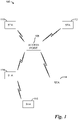
- FIG. 1 illustrates an example wireless communications system 100.
- Wireless communications system 100 includes an access point (AP) 105 that serves one or more stations, such as stations (STA) 110 - 116, by receiving communications originating from the stations and then forwarding the communications to their intended destinations or receiving communications destined to the stations and then forwarding the communications to their intended stations.
- AP 105 access point
- stations stations
- station 116 may transmit directly to station 118. While it is understood that communications systems may employ multiple APs capable of communicating with a number of stations, only one AP, and a number of stations are illustrated for simplicity.
- WLANs make use of carrier sense multiple access with collision avoidance (CSMA/CA), where a station desiring to transmit needs to contend for access to the wireless channel before it can transmit.
- a station may contend for access to the wireless channel using a network allocation vector (NAV).
- the NAV may be set to a first value to represent that the wireless channel is busy and to a second value to represent that the wireless channel is idle.
- the NAV may be set by station in accordance with physical carrier sensing and/or reception of transmissions from other stations and/or APs. Therefore, contending for access to the wireless channel may require the station to expend a significant amount of time, thereby decreasing wireless channel utilization and overall efficiency. Furthermore, contending for access to the wireless channel may become difficult if not impossible as the number of stations contending for access increases.
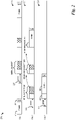
- FIG. 2 illustrates a diagram 200 of example channel access timing.
- a first trace 205 represents channel access for a first station (STA 1)
- a second trace 207 represents channel access for a second station (STA 2)
- a third trace 209 represents channel access for a third station (STA 3).
- a short inter-frame space (SIFS) has a duration of 16 microseconds
- a point coordination function (PCF) inter-frame space (PIFS) has a duration of 25 microseconds
- a distributed inter-frame space (DIFS) may last longer than either the SIFS or the PIFS.
- a backoff period may be a random duration. Therefore, active scanning may not provide the best solution when there are large numbers of stations attempting to perform AP/network discovery.
- OFDMA orthogonal frequency division multiple access
- OFDMA has the ability to support multiple users simultaneously by carrying traffic from different users on different portions of the communications system bandwidth.
- OFDMA can support a large number of users more efficiently, especially when data traffic from individual users is low.
- OFDMA can avoid wasting frequency resources if traffic from one user cannot fill the entirety of the communications system bandwidth by utilizing the unused bandwidth to carry transmissions from other user(s). The ability to utilize unused bandwidth may become crucial as the communications system bandwidth continues to become wider.
- uplink multi-user multiple input multiple output (UL MU-MIMO) techniques have also been used in cellular communications systems, e.g., 3GPP LTE, to enhance communications system performance.
- UL MU-MIMO allows multiple users to simultaneously transmit on the same time-frequency resource(s) with the transmissions being separated in space (i.e., on different spatial streams).
- uplink synchronization is achieved through an evolved NodeB (eNB) sending timing advance commands to user equipments (UE).
- eNBs are also commonly referred to as NodeBs, APs, base stations, controllers, communications controllers, and the like.
- UEs are also commonly referred to as stations, users, subscribers, mobile stations, mobiles, terminals, and the like.
- the timing advance value controls the timing offset of a UE's transmission on the uplink. For UEs that are closer to the eNB (hence with shorter propagation delay), a smaller timing advance value may be used. For UEs that are farther away from the eNB (hence with greater propagation delay), a larger timing advance value may be used. By controlling the uplink transmission timing for different UEs, the eNB can make sure that the arrival time of signals originating from multiple UEs are aligned.
- timing advance commands to a large number of stations may not be feasible.
- IEEE 802.11 compliant communications systems are asynchronous in nature, it is difficult for an AP to estimate the required timing offset for each station due to factors such as the existence of a random backoff interval.
- sending timing advance commands to a large number of stations may consume a considerable amount of resources in the communications system, leading to a large communications system overhead.
- an indicator of the use of OFDMA and/or UL MU-MIMO in the uplink is used to inform stations that OFDMA and/or UL MU-MIMO is being used for uplink transmissions and to adjust their cyclic prefix (CP).
- the length of the cyclic prefix may be based on a value derived from a length of a cyclic prefix used in the transmission of the trigger frame.
- the length of the cyclic prefix used in the transmission of the trigger frame may be indicated in the trigger frame.
- a station receives uplink scheduling information from its AP.
- the uplink scheduling information may be carried in a trigger frame.
- the trigger frame is a stand-alone downlink frame comprising control information such as the uplink scheduling information.
- Another example of the trigger frame is a downlink frame where the control information such as the uplink scheduling information is sent together with other downlink data.
- the trigger frame can be in the form of a MAC frame.
- the trigger frame can also be in the form of a null data packet (NDP) frame.
- the uplink scheduling information may include an indicator of the use of OFDMA and/or UL MU-MIMO.
- the indicator may be set to a first value (e.g., TRUE or ON) to indicate that OFDMA and/or UL MU-MIMO is being used for this uplink transmission, and the indicator may be set to a second value (e.g., FALSE or OFF) to indicate that OFDMA and/or UL MU-MIMO is not being used for this uplink transmission.
- a first value e.g., TRUE or ON
- FALSE or OFF e.g., FALSE or OFF
- the indicator may be an explicit indicator, meaning that it is present in the uplink scheduling information and the station receiving the uplink scheduling information may readily determine the value of the indicator included in the uplink scheduling information.
- the indicator may be an implicit indicator, meaning that the station receiving the scheduling information may infer the value of the indicator by examining the uplink scheduling information intended for the station and/or uplink scheduling information intended for other stations.
- the station may decide on the CP length value for the uplink (CP UL ) that it will use in its uplink transmission as informed by the uplink scheduling information. If the uplink scheduling information includes the indicator set to the second value (i.e., OFDMA and/or UL MU-MIMO is not being used) the station may set its CP UL to a first CP length value (CP1), while if the indicator is set to the first value (i.e., OFDMA and/or UL MU-MIMO is being used) the station may set its CP UL to a second CP length value (CP2), which is derived from CP DL .
- CP1 first CP length value
- CP2 second CP length value
- CP1 may be the same value as CP DL and CP2 is larger than CP DL (and hence CP1) to help accommodate the different propagation delay between different stations and the AP when OFDMA and/or UL MU-MIMO is being used.
- CP2 may be a default value specified by a technical standard, an operator of the communications system, and the like, and may not need to be signaled to the station. It is noted that other values for CP1 and CP2 are possible and that the described relationship of CP1 ⁇ CP2 may not hold in all situations.
- CP2 is derived from a set of possible CP length values.
- a set of possible CP length values is defined (e.g., by a technical standard, an operator of the communications system, and the like) and CP2 is selected from the set of possible CP length values as long as CP2 is larger than or equal to CP DL .
- the set of possible CP length values includes 4 values: 0.4 us, 0.8 us, 1.6 us, and 3.2 us.
- the set of possible CP length values is indexed by a two-bit index: "00", "01", "10", and " 11", respectively.
- the station may derive an index for CP2 by incrementing an index for CP DL by value K.
- the value of K may be a fixed value defined by a technical standard, an operator of the communications system, and the like.
- the value of K may be signaled by an AP in a system information message, e.g., in a Beacon frame. If the resulting index for CP2 is greater than a maximum index value (e.g., the total number of indices), the station sets the index for CP2 to the maximum index value.
- the value of CP2 may be determined from the index of CP2.
- Figure 3a illustrates a flow diagram of example operations 300 occurring in an AP as the AP transmits uplink scheduling information to stations.
- the AP may perform a check to determine if it is using OFDMA and/or UL MU-MIMO for the uplink being scheduled (block 305). If it is, the AP may transmit the uplink scheduling information along with the indicator set to indicate that OFDMA and/or UL MU-MIMO is to be used for the scheduled uplink (block 310). If it is not, the AP may transmit the uplink scheduling information along with the indicator set to indicate that OFDMA and/or UL MU-MIMO is not to be used for the scheduled uplink (block 315).
- the uplink scheduling information may be carried in a trigger frame. In addition to the uplink scheduling information, the trigger frame may also comprise an indicator indicating the cyclic prefix length value for the downlink (e.g., CP DL ).
- Figure 3b illustrates a flow diagram of example operations 350 occurring in a station as the station transmits to its AP.
- the station may receive uplink scheduling information from its AP (block 355).
- the station may also receive the indicator of CP DL from the trigger frame.
- the station may perform a check to determine if OFDMA and/or UL MU-MIMO is going to be used in the uplink (block 360). If OFDMA and/or UL MU-MIMO is going to be used in the uplink, i.e., the indicator is set to the first value (TRUE or ON), the station sets the value of the UL cyclic prefix to CP2, which may be derived from CP DL (block 365) and transmits to the AP (block 370).
- the station sets its cyclic prefix length to CP1 or CP DL (block 375) and transmits to the AP (block 370).
- the station may start its uplink transmission with cyclic prefix length of CP UL on a resource as indicated in the uplink scheduling information.
- the technique as presented herein affords greater flexibility in setting UL cyclic prefix length when OFDMA and/or MU-MIMO is used in the UL since the station can derive the UL cyclic prefix length from the DL cyclic prefix length. Therefore, the orthogonality between signals from the different stations is maintained at the receiver (e.g., the AP).
- the maximum round-trip propagation delay is about 0.67 us.
- the guard interval i.e., CP length
- a longer CP length value for example, 1.6 us, for the UL when UL OFDMA and/or UL MU-MIMO is used, after deducting the maximum round-trip delay of 0.67 us, there still is about 0.93 us left for mitigating channel delay spread and STA timing inaccuracy, which most likely will be sufficient for most of the scenarios.
- low overhead associated with the use of shorter CPs is maintained when longer CPs are not needed.
- OFDMA and/or UL MU-MIMO when OFDMA and/or UL MU-MIMO is not used, the longer CP is not necessary and a shorter CP may be employed, thus reducing the overhead arising from the CP.
- OFDMA and/or UL MU-MIMO although a longer CP is employed, the additional overhead from longer CP will be compensated for due to the use of OFDMA and/or UL MU-MIMO. In fact, additional gain may be achieved due to the use of OFDMA and/or UL MU-MIMO (e.g., supporting transmissions from multiple stations).
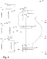
- FIG. 4 illustrates an example interaction 400 between an AP and two stations (STA1 and STA2). It is noted that for simplicity reasons, on both the uplink and the downlink, only one OFDM symbol is shown. In reality, actual downlink and uplink transmissions may occur over a plurality of OFDM symbols.
- the AP transmits uplink scheduling information 405 to STA1 and STA2 on the downlink, with a CP length of CP DL 407.
- the uplink scheduling information includes the indicator that OFDMA is to be used on the scheduled uplink transmissions. Due to propagation delay, after T Delay1 , STA1 receives the uplink scheduling information (shown as uplink scheduling information 409).
- T Delay2 STA2 receives the uplink scheduling information (shown as uplink scheduling information 411).
- uplink scheduling information 411 the uplink scheduling information
- the distance between STA2 and AP is larger than the distance between STA1 and AP, therefore, T Delay2 > T Delay1 .
- STA1 and STA2 check their uplink scheduling information, find their resource allocation information, and also find that OFDMA and/or UL MU-MIMO is to be used in the scheduled uplink transmission, so the stations set the CP length of UL transmission CP UL to CP2, which is larger than CP DL .
- the use of OFDMA and/or UL MU-MIMO may be determined from an implicit indicator or an explicit indicator.
- STA1 and STA2's uplink transmissions arrive at the AP after a delay of T Delay1 and T Delay2 , respectively.
- T Delay1 and T Delay2 the difference of the arrival time of STA1 and STA2's uplink signal at AP receiver is 2 ⁇ (T Delay2 - T Delay1 ).
- the AP receives the uplink transmissions from STA1 and STA2 and performs additional operations accordingly.
- Figure 5 illustrates a message exchange diagram 500 highlighting messages exchanged between a station and its AP, where an indicator of the use of OFDMA and/or UL MU-MIMO is included in uplink scheduling information.
- the AP may determine resource allocations for stations, as well as determine if OFDMA and/or UL MU-MIMO is to be used by the stations in transmissions in the resource allocations (block 505).
- the AP may send UL scheduling information in a trigger frame (shown as event 510).
- the UL scheduling information is sent with a CP length of CP DL .
- the indication of CP DL may also be sent in the trigger frame.
- the station receives the UL scheduling information.
- the station may also receive the indicator of CP DL from the trigger frame. From the UL scheduling information, the station may be able to determine resource allocation information, as well as an indicator if OFDMA and/or UL MU-MIMO are being used in the UL transmission (block 515).
- the station may send an UL transmission in a resource(s) allocated for it (shown as event 520).
- the UL transmission is sent with a CP length of CP UL .
- the station may determine whether the UL scheduling information includes scheduling information for more than one station. If the scheduling information is for more than one station, the station may determine that OFDM and/or MU-MIMO is to be used in the scheduled UL transmission. The station may set its CP UL to CP2, which is derived from CP DL . If the scheduling information is not for more than one station, the station may set its CP UL to CP1. In general, CP2 is larger than CP1.
- Figure 6 illustrates a message exchange diagram 500 highlighting messages exchanged between a station and its AP, where the station determines if OFDMA and/or UL MU-MIMO is being used from the scheduling information.
- the AP may determine resource allocations for stations, as well as determine if OFDMA and/or UL MU-MIMO is to be used by the stations in transmissions in the resource allocations (block 605).
- the AP may send UL scheduling information in a trigger frame (shown as event 610).
- the UL scheduling information is sent with a CP length of CP DL .
- the indication of CP DL may also be sent in the trigger frame.
- the station receives the UL scheduling information. From the UL scheduling information, the station may be able to determine resource allocation information, as well if OFDMA and/or UL MU-MIMO is being used in the UL transmission (block 615).
- the station may send an UL transmission in a resource(s) allocated for it (shown as event 620). The UL transmission is sent with a CP length of CP UL .
- Figure 7a illustrates a flow diagram of example operations 700 occurring in an AP as the AP transmits UL scheduling information.
- Operations 700 may begin with the AP determining resource allocations for stations.
- the AP may transmit UL scheduling information in a trigger frame (block 705).
- the trigger frame may also comprise an indicator indicating the cyclic prefix length value for the downlink (e.g., CP DL ).
- Figure 7b illustrates a flow diagram of example operations 750 occurring in a station as the station transmits on an uplink.
- Operations 750 may begin with the station receiving UL scheduling information (block 755).
- the station may also receive the indicator of CP DL from the trigger frame.
- the UL scheduling information may include information about a resource(s) scheduled for the station.
- the station may perform a test to determine if the UL scheduling information is intended for more than one station (block 760). If the UL scheduling information is intended for more than one station, the station may adjust its CP UL in accordance with CP2, which is derived from CP DL (block 765). While if the UL scheduling information is not intended for more than one station, the station adjust its CP UL in accordance with CP1 (block 770). The station may make the UL transmission with CP value as indicated (block 775).
- a table is used to derive CP2 from CP DL .
- a table (which may be stored in memory of the station) may provide a mapping between DL cyclic prefix length values and UL cyclic prefix length values for UL transmissions.
- the station may select the value of CP2 from CP DL , which is indicated in the trigger message.
- An example table is shown below: DL CP Length (us) UL CP Length for UL MU (us) 0.4 1.6 0.8 1.6 1.6 3.2 3.2 3.2
- CP DL is 0.8 us. From the table shown above, the station may be able to determine that CP2 should be 1.6 us. As another illustrative example, assume that CP DL is 0.4 us. From the table shown above, the station may be able to determine that CP2 should be 1.6 us.
- the table may be defined by a technical standard, an operator of the communications system, and the like. The table may also be signaled to the station in system information, e.g., in a Beacon frame.
- the value of CP2 may be derived from CP DL using a mathematical expression.
- a station receives a trigger frame including a CP DL indicator.
- the station may add a value (CP delta ) to CP DL to obtain CP2, where CP delta represents a difference between UL CP length value for UL transmission and DL CP length value.
- CP delta may be defined in a technical standard, an operator of the communications system, and the like. CP delta may be signaled to the station as system information, e.g., in a Beacon frame.
- the value of CP2 may be derived from CP DL using a mathematical expression.
- a station receives a trigger frame including a CP DL indicator.
- the station may multiply a scaling factor (CP scale ) to CP DL to obtain CP2, where CP scale represents the ratio of UL CP length value for UL transmission to DL CP length value.
- CP scale may be an integer value or a non-integer (i.e., a real number) value.
- CP scale is generally larger than 1.
- CP scale may be defined in a technical standard, an operator of the communications system, and the like. CP scale may be signaled to the station as system information, e.g., in a Beacon frame.
- a cyclic prefix for the uplink (CP UL ) is longer than the cyclic prefix for the downlink (CP DL ), which may help to accommodate different propagation delays between different stations and the AP, thereby maintaining the orthogonality among signals from the different stations at the AP.
- Adaptive cyclic prefix length also helps to maintain low overhead. When OFDMA and/or UL MU-MIMO are not used, longer cyclic prefixes are not necessary and a shorter cyclic prefix may be used, therefore reducing overhead.
- OFDMA and/or UL MU-MIMO When OFDMA and/or UL MU-MIMO is used, longer cyclic prefixes are used, but the increased overhead may be compensated for by the additional gain achieved through the use of OFDMA and/or UL MU-MIMO.
- the example embodiments presented herein also afford greater flexibility in setting UL cyclic prefix length when OFDMA and/or MU-MIMO is used in the UL since the station can derive the UL cyclic prefix length from the DL cyclic prefix length.
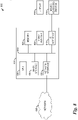
- FIG. 8 is a block diagram of a processing system 800 that may be used for implementing the devices and methods disclosed herein.
- the processing system 800 comprises a UE.
- Specific devices may utilize all of the components shown, or only a subset of the components, and levels of integration may vary from device to device.
- a device may contain multiple instances of a component, such as multiple processing units, processors, memories, transmitters, receivers, etc.
- the processing system may comprise a processing unit 805 equipped with one or more input/output devices, such as a human interface 815 (including speaker, microphone, mouse, touchscreen, keypad, keyboard, printer, and the like), display 810, and so on.
- the processing unit may include a central processing unit (CPU) 820, memory 825, a mass storage device 830, a video adapter 835, and an I/O interface 840 connected to a bus 845.
- CPU central processing unit
- the bus 845 may be one or more of any type of several bus architectures including a memory bus or memory controller, a peripheral bus, video bus, or the like.
- the CPU 820 may comprise any type of electronic data processor.
- the memory 825 may comprise any type of system memory such as static random access memory (SRAM), dynamic random access memory (DRAM), synchronous DRAM (SDRAM), read-only memory (ROM), a combination thereof, or the like.
- SRAM static random access memory
- DRAM dynamic random access memory
- SDRAM synchronous DRAM
- ROM read-only memory
- the memory 825 may include ROM for use at boot-up, and DRAM for program and data storage for use while executing programs.
- the mass storage device 830 may comprise any type of storage device configured to store data, programs, and other information and to make the data, programs, and other information accessible via the bus 845.
- the mass storage device 830 may comprise, for example, one or more of a solid state drive, hard disk drive, a magnetic disk drive, an optical disk drive, or the like.
- the video adapter 835 and the I/O interface 840 provide interfaces to couple external input and output devices to the processing unit 800.
- input and output devices include the display 810 coupled to the video adapter 835 and the mouse/keyboard/printer 815 coupled to the I/O interface 840.
- Other devices may be coupled to the processing unit 800, and additional or fewer interface devices may be utilized.
- a serial interface such as Universal Serial Bus (USB) (not shown) may be used to provide an interface for a printer.
- USB Universal Serial Bus
- the processing unit 800 also includes one or more network interfaces 850, which may comprise wired links, such as an Ethernet cable or the like, and/or wireless links to access nodes or different networks 855.
- the network interface 850 allows the processing unit 800 to communicate with remote units via the networks 855.
- the network interface 850 may provide wireless communication via one or more transmitters/transmit antennas and one or more receivers/receive antennas.
- the processing unit 800 is coupled to a local-area network or a wide-area network 855 for data processing and communications with remote devices, such as other processing units, the Internet, remote storage facilities, or the like.
Landscapes
- Engineering & Computer Science (AREA)
- Signal Processing (AREA)
- Computer Networks & Wireless Communication (AREA)
- Mobile Radio Communication Systems (AREA)
Applications Claiming Priority (4)
| Application Number | Priority Date | Filing Date | Title |
|---|---|---|---|
| US201462082234P | 2014-11-20 | 2014-11-20 | |
| US14/869,411 US10749724B2 (en) | 2014-11-20 | 2015-09-29 | System and method for setting cyclic prefix length |
| PCT/CN2015/094304 WO2016078524A1 (en) | 2014-11-20 | 2015-11-11 | System and method for setting cyclic prefix length |
| EP15860644.2A EP3213576B1 (en) | 2014-11-20 | 2015-11-11 | System and method for setting cyclic prefix length |
Related Parent Applications (2)
| Application Number | Title | Priority Date | Filing Date |
|---|---|---|---|
| EP15860644.2A Division-Into EP3213576B1 (en) | 2014-11-20 | 2015-11-11 | System and method for setting cyclic prefix length |
| EP15860644.2A Division EP3213576B1 (en) | 2014-11-20 | 2015-11-11 | System and method for setting cyclic prefix length |
Publications (2)
| Publication Number | Publication Date |
|---|---|
| EP3860071A1 EP3860071A1 (en) | 2021-08-04 |
| EP3860071B1 true EP3860071B1 (en) | 2022-11-02 |
Family
ID=56011315
Family Applications (2)
| Application Number | Title | Priority Date | Filing Date |
|---|---|---|---|
| EP21165237.5A Active EP3860071B1 (en) | 2014-11-20 | 2015-11-11 | System and method for setting cyclic prefix length |
| EP15860644.2A Active EP3213576B1 (en) | 2014-11-20 | 2015-11-11 | System and method for setting cyclic prefix length |
Family Applications After (1)
| Application Number | Title | Priority Date | Filing Date |
|---|---|---|---|
| EP15860644.2A Active EP3213576B1 (en) | 2014-11-20 | 2015-11-11 | System and method for setting cyclic prefix length |
Country Status (8)
Families Citing this family (14)
| Publication number | Priority date | Publication date | Assignee | Title |
|---|---|---|---|---|
| JP2018074179A (ja) * | 2015-03-11 | 2018-05-10 | シャープ株式会社 | 無線受信装置、無線送信装置、通信方法および通信システム |
| CN107710708B (zh) * | 2015-06-11 | 2021-05-07 | 瑞士优北罗股份有限公司 | 调制解调器装置、通信系统和处理循环前缀的方法 |
| WO2017140477A1 (en) * | 2016-02-15 | 2017-08-24 | Telefonaktiebolaget Lm Ericsson (Publ) | Method and apparatus for generating nb-iot ofdm signals with a lower sampling rate |
| WO2017140651A1 (en) | 2016-02-15 | 2017-08-24 | Telefonaktiebolaget Lm Ericsson (Publ) | Receiver circuit and methods |
| CN116170264A (zh) * | 2016-03-03 | 2023-05-26 | 北京三星通信技术研究有限公司 | 基于滤波的信号发送、接收方法及相应的发射机与接收机 |
| WO2017213420A1 (ko) * | 2016-06-07 | 2017-12-14 | 엘지전자(주) | 무선 통신 시스템에서 순환 전치에 대한 정보를 획득하는 방법 및 이를 위한 장치 |
| EP3490314B1 (en) * | 2016-07-22 | 2020-12-16 | LG Electronics Inc. -1- | Method and device for transmitting uplink |
| US11050599B2 (en) | 2016-09-30 | 2021-06-29 | Huawei Technologies Co., Ltd. | Timing adjustment free solution to uplink synchronous operations |
| WO2018151446A1 (ko) * | 2017-02-20 | 2018-08-23 | 엘지전자 주식회사 | 무선랜 시스템에서 웨이크업 패킷을 송신하는 방법 및 장치 |
| WO2018155835A1 (ko) * | 2017-02-26 | 2018-08-30 | 엘지전자 주식회사 | 무선랜 시스템에서 웨이크업 패킷을 송신하는 방법 및 장치 |
| CN109831824B (zh) * | 2017-11-23 | 2021-06-01 | 华为技术有限公司 | 用于上行捎带传输的方法、装置及系统 |
| EP3804172A4 (en) * | 2018-06-06 | 2022-01-19 | Nokia Technologies Oy | METHODS, APPARATUS AND COMPUTER READABLE MEDIUM FOR DETERMINING A TIME ADVANCE |
| US11894962B2 (en) | 2019-07-11 | 2024-02-06 | Telefonaktiebolaget Lm Ericsson (Publ) | Guard interval adaptation for coordinated beamforming |
| US11528757B2 (en) * | 2020-10-30 | 2022-12-13 | Qualcomm Incorporated | Dynamic cyclic prefix selection |
Family Cites Families (38)
| Publication number | Priority date | Publication date | Assignee | Title |
|---|---|---|---|---|
| US20060176966A1 (en) | 2005-02-07 | 2006-08-10 | Stewart Kenneth A | Variable cyclic prefix in mixed-mode wireless communication systems |
| JP4463723B2 (ja) | 2005-04-28 | 2010-05-19 | 株式会社エヌ・ティ・ティ・ドコモ | 送信機及び送信方法 |
| US7480268B2 (en) | 2005-07-28 | 2009-01-20 | Symbol Technologies, Inc. | System and method for multiprotocol wireless communication |
| CN101079688B (zh) | 2006-05-23 | 2010-09-01 | 中兴通讯股份有限公司 | 一种正交频分复用系统中实现同步的方法 |
| US20090125363A1 (en) | 2007-10-22 | 2009-05-14 | Nokia Siemens Networks Oy | Method, apparatus and computer program for employing a frame structure in wireless communication |
| WO2009072171A1 (ja) | 2007-12-03 | 2009-06-11 | Fujitsu Limited | Ofdm通信方法及びofdm通信装置 |
| CN101640579B (zh) | 2008-07-30 | 2013-05-08 | 电信科学技术研究院 | 自适应调制和编码方法、系统及装置 |
| JP5260742B2 (ja) | 2008-07-30 | 2013-08-14 | チャイナ アカデミー オブ テレコミュニケーションズ テクノロジー | 適応変調及び符号化方法、システム及び装置 |
| US8867461B2 (en) * | 2008-08-11 | 2014-10-21 | Lg Electronics Inc. | Method of transmitting or receiving uplink signals and equipment therefor |
| JP4465020B2 (ja) | 2008-09-26 | 2010-05-19 | 株式会社エヌ・ティ・ティ・ドコモ | 移動局及び無線基地局 |
| CN101772170A (zh) * | 2009-01-04 | 2010-07-07 | 中兴通讯股份有限公司 | 通信系统中的系统信息管理及传输方法 |
| CN101790202B (zh) | 2009-01-23 | 2013-07-10 | 电信科学技术研究院 | 一种循环前缀的配置方法、基站和终端 |
| US20100329236A1 (en) | 2009-06-26 | 2010-12-30 | Qualcomm Incorporated | Method and apparatus for multiple user uplink requiring minimal station timing and frequency synchronization |
| US8848624B2 (en) | 2009-08-17 | 2014-09-30 | Broadcom Corporation | Multi-user uplink communications within multiple user, multiple access, and/or MIMO wireless communication systems |
| WO2011034386A2 (en) * | 2009-09-19 | 2011-03-24 | Samsung Electronics Co., Ltd. | Apparatus and method for configuring frame structure in relay wireless communication system |
| US20120270535A1 (en) * | 2009-12-17 | 2012-10-25 | Texas Instruments Incorporated | Implicit CSI Feedback for DL Multiuser MIMO Transmission |
| US9166745B2 (en) | 2010-12-31 | 2015-10-20 | Telefonaktiebolaget L M Ericsson (Publ) | Allocation of acknowledgement channels to channel groups having variable transmit energies |
| US9300511B2 (en) * | 2011-01-05 | 2016-03-29 | Qualcomm Incorporated | Method and apparatus for improving throughput of 5 MHZ WLAN transmissions |
| US8422577B1 (en) * | 2011-03-25 | 2013-04-16 | Sprint Spectrum L.P. | Method and system for selecting cyclic prefix length based on signal quality reports |
| US8565082B1 (en) | 2011-03-25 | 2013-10-22 | Sprint Spectrum L.P. | Method and system for selecting cyclic prefix length based on access point load |
| US8792369B2 (en) | 2011-05-02 | 2014-07-29 | Broadcom Corporation | Method for setting a mobile node specific cyclic prefix in a mobile communication |
| WO2013005904A1 (ko) | 2011-07-01 | 2013-01-10 | 엘지전자 주식회사 | 셀 측정 방법 및 단말 |
| WO2013010247A1 (en) | 2011-07-21 | 2013-01-24 | Research In Motion Limited | Dynamic cyclic prefix mode for uplink radio resource management |
| CN103733552A (zh) | 2011-08-11 | 2014-04-16 | 交互数字专利控股公司 | 回程中继的多输入多输出(mimo)增强 |
| US9531573B2 (en) * | 2012-04-09 | 2016-12-27 | Samsung Electronics Co., Ltd. | Methods and apparatus for cyclic prefix reduction in MMwave mobile communication systems |
| US8712331B2 (en) | 2012-04-13 | 2014-04-29 | Motorola Solutions, Inc. | Methods and apparatus for mitigating interference between co-located collaborating radios |
| US8867638B2 (en) | 2012-04-16 | 2014-10-21 | Qualcomm Incorporated | Variable-length cyclic prefixes in OFDM coaxial communications |
| US10020971B2 (en) * | 2012-10-29 | 2018-07-10 | Lg Electronics Inc. | Method and user equipment for transreceiving TDD |
| WO2014112907A1 (en) | 2013-01-21 | 2014-07-24 | Telefonaktiebolaget Lm Ericsson (Publ) | Method and arrangement for communication using a dynamic transmission parameter |
| CA2911262C (en) * | 2013-05-07 | 2020-06-30 | Lg Electronics Inc. | Method and device for transmitting data unit |
| US9184968B2 (en) * | 2013-07-17 | 2015-11-10 | Telefonaktiebolaget L M Ericsson (Publ) | Apparatuses, methods, and computer program products for selecting a cyclic prefix length |
| US10135652B2 (en) | 2013-10-24 | 2018-11-20 | Futurewei Technologies, Inc. | System and method for setting cyclic prefix length |
| US20160249381A1 (en) * | 2013-10-29 | 2016-08-25 | Lg Electronics Inc. | Method of transmitting data and device using the same |
| CN106416165B (zh) * | 2014-04-16 | 2019-08-13 | 马维尔国际贸易有限公司 | 用于生成和处理物理层数据单元的方法和用于通信的装置 |
| EP4297357A3 (en) * | 2014-06-27 | 2024-04-03 | Samsung Electronics Co., Ltd. | Method and device for transmitting data |
| US9413581B2 (en) * | 2014-10-08 | 2016-08-09 | Newracom, Inc. | System and method for synchronization for OFDMA transmission |
| US9510311B2 (en) * | 2014-10-09 | 2016-11-29 | Qualcomm Incorporated | Open-loop timing and cyclic prefixes in cellular internet of things communication |
| WO2016068571A2 (ko) * | 2014-10-27 | 2016-05-06 | 엘지전자 주식회사 | 무선랜 시스템에서 상향링크 다중 사용자 데이터에 대한 확인응답 신호 송수신 방법 및 이를 위한 장치 |
-
2015
- 2015-09-29 US US14/869,411 patent/US10749724B2/en active Active
- 2015-11-11 ES ES21165237T patent/ES2936646T3/es active Active
- 2015-11-11 PL PL15860644T patent/PL3213576T3/pl unknown
- 2015-11-11 KR KR1020177016861A patent/KR102071564B1/ko active Active
- 2015-11-11 EP EP21165237.5A patent/EP3860071B1/en active Active
- 2015-11-11 KR KR1020207002299A patent/KR102205775B1/ko active Active
- 2015-11-11 EP EP15860644.2A patent/EP3213576B1/en active Active
- 2015-11-11 ES ES15860644T patent/ES2882171T3/es active Active
- 2015-11-11 CN CN201580063192.3A patent/CN107251629B/zh active Active
- 2015-11-11 JP JP2017527597A patent/JP6482666B2/ja active Active
- 2015-11-11 WO PCT/CN2015/094304 patent/WO2016078524A1/en active Application Filing
-
2019
- 2019-02-08 JP JP2019021560A patent/JP6884805B2/ja active Active
-
2020
- 2020-02-12 US US16/789,113 patent/US11290315B2/en active Active
Also Published As
| Publication number | Publication date |
|---|---|
| KR102071564B1 (ko) | 2020-01-30 |
| JP2019083577A (ja) | 2019-05-30 |
| EP3213576B1 (en) | 2021-05-19 |
| JP6482666B2 (ja) | 2019-03-13 |
| US20200213175A1 (en) | 2020-07-02 |
| WO2016078524A1 (en) | 2016-05-26 |
| CN107251629B (zh) | 2020-10-09 |
| ES2882171T3 (es) | 2021-12-01 |
| KR20200011600A (ko) | 2020-02-03 |
| US11290315B2 (en) | 2022-03-29 |
| EP3213576A1 (en) | 2017-09-06 |
| JP2018501705A (ja) | 2018-01-18 |
| KR20170085584A (ko) | 2017-07-24 |
| EP3860071A1 (en) | 2021-08-04 |
| PL3213576T3 (pl) | 2021-11-22 |
| CN107251629A (zh) | 2017-10-13 |
| KR102205775B1 (ko) | 2021-01-20 |
| US20160149743A1 (en) | 2016-05-26 |
| US10749724B2 (en) | 2020-08-18 |
| ES2936646T3 (es) | 2023-03-21 |
| EP3213576A4 (en) | 2017-11-15 |
| JP6884805B2 (ja) | 2021-06-09 |
Similar Documents
| Publication | Publication Date | Title |
|---|---|---|
| US11290315B2 (en) | System and method for setting cyclic prefix length | |
| US10135652B2 (en) | System and method for setting cyclic prefix length | |
| US10542557B2 (en) | System and method for digital communications with interference avoidance | |
| US10205573B2 (en) | System and method for OFDMA PS-poll transmission | |
| US9967827B2 (en) | System and method for power control | |
| US10050746B2 (en) | System and method for orthogonal frequency division multiple access power-saving poll transmission |
Legal Events
| Date | Code | Title | Description |
|---|---|---|---|
| PUAI | Public reference made under article 153(3) epc to a published international application that has entered the european phase |
Free format text: ORIGINAL CODE: 0009012 |
|
| STAA | Information on the status of an ep patent application or granted ep patent |
Free format text: STATUS: REQUEST FOR EXAMINATION WAS MADE |
|
| 17P | Request for examination filed |
Effective date: 20210326 |
|
| AC | Divisional application: reference to earlier application |
Ref document number: 3213576 Country of ref document: EP Kind code of ref document: P |
|
| AK | Designated contracting states |
Kind code of ref document: A1 Designated state(s): AL AT BE BG CH CY CZ DE DK EE ES FI FR GB GR HR HU IE IS IT LI LT LU LV MC MK MT NL NO PL PT RO RS SE SI SK SM TR |
|
| GRAP | Despatch of communication of intention to grant a patent |
Free format text: ORIGINAL CODE: EPIDOSNIGR1 |
|
| STAA | Information on the status of an ep patent application or granted ep patent |
Free format text: STATUS: GRANT OF PATENT IS INTENDED |
|
| RIC1 | Information provided on ipc code assigned before grant |
Ipc: H04W 84/12 20090101ALN20220421BHEP Ipc: H04W 72/12 20090101ALN20220421BHEP Ipc: H04B 7/0452 20170101ALI20220421BHEP Ipc: H04L 27/26 20060101AFI20220421BHEP |
|
| INTG | Intention to grant announced |
Effective date: 20220513 |
|
| GRAS | Grant fee paid |
Free format text: ORIGINAL CODE: EPIDOSNIGR3 |
|
| GRAA | (expected) grant |
Free format text: ORIGINAL CODE: 0009210 |
|
| STAA | Information on the status of an ep patent application or granted ep patent |
Free format text: STATUS: THE PATENT HAS BEEN GRANTED |
|
| AC | Divisional application: reference to earlier application |
Ref document number: 3213576 Country of ref document: EP Kind code of ref document: P |
|
| AK | Designated contracting states |
Kind code of ref document: B1 Designated state(s): AL AT BE BG CH CY CZ DE DK EE ES FI FR GB GR HR HU IE IS IT LI LT LU LV MC MK MT NL NO PL PT RO RS SE SI SK SM TR |
|
| REG | Reference to a national code |
Ref country code: GB Ref legal event code: FG4D |
|
| REG | Reference to a national code |
Ref country code: CH Ref legal event code: EP Ref country code: AT Ref legal event code: REF Ref document number: 1529592 Country of ref document: AT Kind code of ref document: T Effective date: 20221115 |
|
| REG | Reference to a national code |
Ref country code: DE Ref legal event code: R096 Ref document number: 602015081502 Country of ref document: DE |
|
| REG | Reference to a national code |
Ref country code: IE Ref legal event code: FG4D |
|
| REG | Reference to a national code |
Ref country code: LT Ref legal event code: MG9D |
|
| REG | Reference to a national code |
Ref country code: NL Ref legal event code: MP Effective date: 20221102 |
|
| REG | Reference to a national code |
Ref country code: ES Ref legal event code: FG2A Ref document number: 2936646 Country of ref document: ES Kind code of ref document: T3 Effective date: 20230321 |
|
| REG | Reference to a national code |
Ref country code: AT Ref legal event code: MK05 Ref document number: 1529592 Country of ref document: AT Kind code of ref document: T Effective date: 20221102 |
|
| PG25 | Lapsed in a contracting state [announced via postgrant information from national office to epo] |
Ref country code: SE Free format text: LAPSE BECAUSE OF FAILURE TO SUBMIT A TRANSLATION OF THE DESCRIPTION OR TO PAY THE FEE WITHIN THE PRESCRIBED TIME-LIMIT Effective date: 20221102 Ref country code: PT Free format text: LAPSE BECAUSE OF FAILURE TO SUBMIT A TRANSLATION OF THE DESCRIPTION OR TO PAY THE FEE WITHIN THE PRESCRIBED TIME-LIMIT Effective date: 20230302 Ref country code: NO Free format text: LAPSE BECAUSE OF FAILURE TO SUBMIT A TRANSLATION OF THE DESCRIPTION OR TO PAY THE FEE WITHIN THE PRESCRIBED TIME-LIMIT Effective date: 20230202 Ref country code: LT Free format text: LAPSE BECAUSE OF FAILURE TO SUBMIT A TRANSLATION OF THE DESCRIPTION OR TO PAY THE FEE WITHIN THE PRESCRIBED TIME-LIMIT Effective date: 20221102 Ref country code: FI Free format text: LAPSE BECAUSE OF FAILURE TO SUBMIT A TRANSLATION OF THE DESCRIPTION OR TO PAY THE FEE WITHIN THE PRESCRIBED TIME-LIMIT Effective date: 20221102 Ref country code: AT Free format text: LAPSE BECAUSE OF FAILURE TO SUBMIT A TRANSLATION OF THE DESCRIPTION OR TO PAY THE FEE WITHIN THE PRESCRIBED TIME-LIMIT Effective date: 20221102 |
|
| PG25 | Lapsed in a contracting state [announced via postgrant information from national office to epo] |
Ref country code: RS Free format text: LAPSE BECAUSE OF FAILURE TO SUBMIT A TRANSLATION OF THE DESCRIPTION OR TO PAY THE FEE WITHIN THE PRESCRIBED TIME-LIMIT Effective date: 20221102 Ref country code: PL Free format text: LAPSE BECAUSE OF FAILURE TO SUBMIT A TRANSLATION OF THE DESCRIPTION OR TO PAY THE FEE WITHIN THE PRESCRIBED TIME-LIMIT Effective date: 20221102 Ref country code: LV Free format text: LAPSE BECAUSE OF FAILURE TO SUBMIT A TRANSLATION OF THE DESCRIPTION OR TO PAY THE FEE WITHIN THE PRESCRIBED TIME-LIMIT Effective date: 20221102 Ref country code: IS Free format text: LAPSE BECAUSE OF FAILURE TO SUBMIT A TRANSLATION OF THE DESCRIPTION OR TO PAY THE FEE WITHIN THE PRESCRIBED TIME-LIMIT Effective date: 20230302 Ref country code: HR Free format text: LAPSE BECAUSE OF FAILURE TO SUBMIT A TRANSLATION OF THE DESCRIPTION OR TO PAY THE FEE WITHIN THE PRESCRIBED TIME-LIMIT Effective date: 20221102 Ref country code: GR Free format text: LAPSE BECAUSE OF FAILURE TO SUBMIT A TRANSLATION OF THE DESCRIPTION OR TO PAY THE FEE WITHIN THE PRESCRIBED TIME-LIMIT Effective date: 20230203 |
|
| PG25 | Lapsed in a contracting state [announced via postgrant information from national office to epo] |
Ref country code: NL Free format text: LAPSE BECAUSE OF FAILURE TO SUBMIT A TRANSLATION OF THE DESCRIPTION OR TO PAY THE FEE WITHIN THE PRESCRIBED TIME-LIMIT Effective date: 20221102 |
|
| REG | Reference to a national code |
Ref country code: CH Ref legal event code: PL |
|
| REG | Reference to a national code |
Ref country code: BE Ref legal event code: MM Effective date: 20221130 |
|
| PG25 | Lapsed in a contracting state [announced via postgrant information from national office to epo] |
Ref country code: SM Free format text: LAPSE BECAUSE OF FAILURE TO SUBMIT A TRANSLATION OF THE DESCRIPTION OR TO PAY THE FEE WITHIN THE PRESCRIBED TIME-LIMIT Effective date: 20221102 Ref country code: RO Free format text: LAPSE BECAUSE OF FAILURE TO SUBMIT A TRANSLATION OF THE DESCRIPTION OR TO PAY THE FEE WITHIN THE PRESCRIBED TIME-LIMIT Effective date: 20221102 Ref country code: LI Free format text: LAPSE BECAUSE OF NON-PAYMENT OF DUE FEES Effective date: 20221130 Ref country code: EE Free format text: LAPSE BECAUSE OF FAILURE TO SUBMIT A TRANSLATION OF THE DESCRIPTION OR TO PAY THE FEE WITHIN THE PRESCRIBED TIME-LIMIT Effective date: 20221102 Ref country code: DK Free format text: LAPSE BECAUSE OF FAILURE TO SUBMIT A TRANSLATION OF THE DESCRIPTION OR TO PAY THE FEE WITHIN THE PRESCRIBED TIME-LIMIT Effective date: 20221102 Ref country code: CZ Free format text: LAPSE BECAUSE OF FAILURE TO SUBMIT A TRANSLATION OF THE DESCRIPTION OR TO PAY THE FEE WITHIN THE PRESCRIBED TIME-LIMIT Effective date: 20221102 Ref country code: CH Free format text: LAPSE BECAUSE OF NON-PAYMENT OF DUE FEES Effective date: 20221130 |
|
| REG | Reference to a national code |
Ref country code: DE Ref legal event code: R097 Ref document number: 602015081502 Country of ref document: DE |
|
| PG25 | Lapsed in a contracting state [announced via postgrant information from national office to epo] |
Ref country code: SK Free format text: LAPSE BECAUSE OF FAILURE TO SUBMIT A TRANSLATION OF THE DESCRIPTION OR TO PAY THE FEE WITHIN THE PRESCRIBED TIME-LIMIT Effective date: 20221102 Ref country code: LU Free format text: LAPSE BECAUSE OF NON-PAYMENT OF DUE FEES Effective date: 20221111 Ref country code: AL Free format text: LAPSE BECAUSE OF FAILURE TO SUBMIT A TRANSLATION OF THE DESCRIPTION OR TO PAY THE FEE WITHIN THE PRESCRIBED TIME-LIMIT Effective date: 20221102 |
|
| PLBE | No opposition filed within time limit |
Free format text: ORIGINAL CODE: 0009261 |
|
| STAA | Information on the status of an ep patent application or granted ep patent |
Free format text: STATUS: NO OPPOSITION FILED WITHIN TIME LIMIT |
|
| 26N | No opposition filed |
Effective date: 20230803 |
|
| PG25 | Lapsed in a contracting state [announced via postgrant information from national office to epo] |
Ref country code: IE Free format text: LAPSE BECAUSE OF NON-PAYMENT OF DUE FEES Effective date: 20221111 |
|
| PG25 | Lapsed in a contracting state [announced via postgrant information from national office to epo] |
Ref country code: SI Free format text: LAPSE BECAUSE OF FAILURE TO SUBMIT A TRANSLATION OF THE DESCRIPTION OR TO PAY THE FEE WITHIN THE PRESCRIBED TIME-LIMIT Effective date: 20221102 Ref country code: BE Free format text: LAPSE BECAUSE OF NON-PAYMENT OF DUE FEES Effective date: 20221130 |
|
| PG25 | Lapsed in a contracting state [announced via postgrant information from national office to epo] |
Ref country code: CY Free format text: LAPSE BECAUSE OF FAILURE TO SUBMIT A TRANSLATION OF THE DESCRIPTION OR TO PAY THE FEE WITHIN THE PRESCRIBED TIME-LIMIT Effective date: 20221102 |
|
| PG25 | Lapsed in a contracting state [announced via postgrant information from national office to epo] |
Ref country code: MK Free format text: LAPSE BECAUSE OF FAILURE TO SUBMIT A TRANSLATION OF THE DESCRIPTION OR TO PAY THE FEE WITHIN THE PRESCRIBED TIME-LIMIT Effective date: 20221102 Ref country code: HU Free format text: LAPSE BECAUSE OF FAILURE TO SUBMIT A TRANSLATION OF THE DESCRIPTION OR TO PAY THE FEE WITHIN THE PRESCRIBED TIME-LIMIT; INVALID AB INITIO Effective date: 20151111 |
|
| PG25 | Lapsed in a contracting state [announced via postgrant information from national office to epo] |
Ref country code: MC Free format text: LAPSE BECAUSE OF FAILURE TO SUBMIT A TRANSLATION OF THE DESCRIPTION OR TO PAY THE FEE WITHIN THE PRESCRIBED TIME-LIMIT Effective date: 20221102 |
|
| PG25 | Lapsed in a contracting state [announced via postgrant information from national office to epo] |
Ref country code: MC Free format text: LAPSE BECAUSE OF FAILURE TO SUBMIT A TRANSLATION OF THE DESCRIPTION OR TO PAY THE FEE WITHIN THE PRESCRIBED TIME-LIMIT Effective date: 20221102 |
|
| PG25 | Lapsed in a contracting state [announced via postgrant information from national office to epo] |
Ref country code: BG Free format text: LAPSE BECAUSE OF FAILURE TO SUBMIT A TRANSLATION OF THE DESCRIPTION OR TO PAY THE FEE WITHIN THE PRESCRIBED TIME-LIMIT Effective date: 20221102 |
|
| PG25 | Lapsed in a contracting state [announced via postgrant information from national office to epo] |
Ref country code: MT Free format text: LAPSE BECAUSE OF FAILURE TO SUBMIT A TRANSLATION OF THE DESCRIPTION OR TO PAY THE FEE WITHIN THE PRESCRIBED TIME-LIMIT Effective date: 20221102 |
|
| PGFP | Annual fee paid to national office [announced via postgrant information from national office to epo] |
Ref country code: DE Payment date: 20241001 Year of fee payment: 10 |
|
| PGFP | Annual fee paid to national office [announced via postgrant information from national office to epo] |
Ref country code: GB Payment date: 20241001 Year of fee payment: 10 |
|
| PGFP | Annual fee paid to national office [announced via postgrant information from national office to epo] |
Ref country code: FR Payment date: 20241001 Year of fee payment: 10 |
|
| PGFP | Annual fee paid to national office [announced via postgrant information from national office to epo] |
Ref country code: IT Payment date: 20241010 Year of fee payment: 10 Ref country code: ES Payment date: 20241206 Year of fee payment: 10 |