EP3859984B1 - Melt bei rückleistungsspeisung - Google Patents
Melt bei rückleistungsspeisung Download PDFInfo
- Publication number
- EP3859984B1 EP3859984B1 EP20154725.4A EP20154725A EP3859984B1 EP 3859984 B1 EP3859984 B1 EP 3859984B1 EP 20154725 A EP20154725 A EP 20154725A EP 3859984 B1 EP3859984 B1 EP 3859984B1
- Authority
- EP
- European Patent Office
- Prior art keywords
- transmission line
- network node
- line
- power
- further configured
- Prior art date
- Legal status (The legal status is an assumption and is not a legal conclusion. Google has not performed a legal analysis and makes no representation as to the accuracy of the status listed.)
- Active
Links
- 230000005540 biological transmission Effects 0.000 claims description 195
- 238000005259 measurement Methods 0.000 claims description 82
- 238000000034 method Methods 0.000 claims description 31
- 238000004891 communication Methods 0.000 claims description 30
- 238000012544 monitoring process Methods 0.000 claims description 24
- 230000011664 signaling Effects 0.000 claims description 19
- 239000000155 melt Substances 0.000 description 37
- 238000001514 detection method Methods 0.000 description 31
- 238000012360 testing method Methods 0.000 description 18
- 238000004590 computer program Methods 0.000 description 5
- 238000005516 engineering process Methods 0.000 description 4
- 230000006399 behavior Effects 0.000 description 3
- 238000007726 management method Methods 0.000 description 3
- 230000009286 beneficial effect Effects 0.000 description 2
- 230000006870 function Effects 0.000 description 2
- 238000012358 sourcing Methods 0.000 description 2
- 230000001960 triggered effect Effects 0.000 description 2
- RYGMFSIKBFXOCR-UHFFFAOYSA-N Copper Chemical compound [Cu] RYGMFSIKBFXOCR-UHFFFAOYSA-N 0.000 description 1
- 230000000295 complement effect Effects 0.000 description 1
- 229910052802 copper Inorganic materials 0.000 description 1
- 239000010949 copper Substances 0.000 description 1
- 230000001419 dependent effect Effects 0.000 description 1
- 238000012423 maintenance Methods 0.000 description 1
- 230000004044 response Effects 0.000 description 1
Images


Classifications
-
- H—ELECTRICITY
- H04—ELECTRIC COMMUNICATION TECHNIQUE
- H04L—TRANSMISSION OF DIGITAL INFORMATION, e.g. TELEGRAPHIC COMMUNICATION
- H04L43/00—Arrangements for monitoring or testing data switching networks
- H04L43/50—Testing arrangements
-
- H—ELECTRICITY
- H04—ELECTRIC COMMUNICATION TECHNIQUE
- H04B—TRANSMISSION
- H04B3/00—Line transmission systems
- H04B3/02—Details
- H04B3/46—Monitoring; Testing
-
- H—ELECTRICITY
- H04—ELECTRIC COMMUNICATION TECHNIQUE
- H04B—TRANSMISSION
- H04B3/00—Line transmission systems
- H04B3/54—Systems for transmission via power distribution lines
-
- H—ELECTRICITY
- H04—ELECTRIC COMMUNICATION TECHNIQUE
- H04L—TRANSMISSION OF DIGITAL INFORMATION, e.g. TELEGRAPHIC COMMUNICATION
- H04L12/00—Data switching networks
- H04L12/02—Details
- H04L12/10—Current supply arrangements
-
- H—ELECTRICITY
- H04—ELECTRIC COMMUNICATION TECHNIQUE
- H04L—TRANSMISSION OF DIGITAL INFORMATION, e.g. TELEGRAPHIC COMMUNICATION
- H04L43/00—Arrangements for monitoring or testing data switching networks
- H04L43/08—Monitoring or testing based on specific metrics, e.g. QoS, energy consumption or environmental parameters
-
- H—ELECTRICITY
- H04—ELECTRIC COMMUNICATION TECHNIQUE
- H04M—TELEPHONIC COMMUNICATION
- H04M11/00—Telephonic communication systems specially adapted for combination with other electrical systems
- H04M11/06—Simultaneous speech and data transmission, e.g. telegraphic transmission over the same conductors
- H04M11/062—Simultaneous speech and data transmission, e.g. telegraphic transmission over the same conductors using different frequency bands for speech and other data
Definitions
- the present disclosure generally relates to measurement in network systems.
- the present disclosure relates to power management for facilitating measurement in network systems where reverse powering is deployed.
- DSL Digital Subscriber Line
- ADSL Asymmetric DSL
- VDSL Very high bit-rate DSL
- DSL Digital Subscriber Line
- Metallic line testing is a test mechanism for testing twisted pairs. It is typically used to monitor the quality of the twisted pair and to debug issues in the field. Circuitry to perform these measurements are typically integrated at the operator side of the twisted pair loop, for example within a Distribution Point Unit, hereafter abbreviated in this document by DPU. In general, the mechanism relies on measuring foreign DC and AC voltages, resistances and/or capacitances between Tip and Ring, Ring to earth and/or Tip to earth.
- a test voltage, through a relative high impedance, within the frequency range from DC to 4 kHz may be set between Tip and Ring or between Tip/Ring and earth, such that the resulting current can be measured.
- RPF Reverse Power Feed
- PSE Power Sourcing Equipment
- PS Power Splitter
- PE Power Extractor
- This voltage source typically provides a low output impedance between Tip and Ring on the line, needed to provide DC power to the DPU over the twisted pair. Notably, this voltage source may prevent a DPU from executing MELT tests.
- Access, Terminals, Transmission and Multiplexing discloses an architecture for reverse powering of remote network nodes from multiple customer premises equipment (CPEs), wherein a single start-up protocol for reverse powering is defined to ensure safe connection of reverse powered systems, and wherein the remote powered device (RPD) shall notify the CPE to remove reverse powering for to-be-defined seconds in case of performing Metallic loop testing.
- CPEs customer premises equipment
- RPD remote powered device
- RPF Startup requirements (#2015.0295) proposes the RPF and DPU start-up requirements for Communications Based Start-Up (CBSU) and Metallic Detection Start-Up (MDSU), including supporting CBSU and MDSU on every customer pair, upon detection of either the CBSU or MDSU procedure on a given pair, disconnecting any exchange connection to that pair, and sourcing enough power from a connected exchange line or the line that is attempting to start up to operate the CBSU or MDSU procedure on any customer pair.
- CBSU Communications Based Start-Up
- MDSU Metallic Detection Start-Up
- Method of disconnecting Exchange feed voltage from RPF lines discloses a method to remove Exchange feed voltage from RPF lines which can be used as a complementary optional feature for the existing MDSU protocol, including performing PSE detection of an Exchange voltage, performing PSE signaling to Exchange to remove the voltage, decoding the signaling and removing the Exchange voltage.
- a network node couplable via a transmission line to an apparatus as set out in independent claim 1 an apparatus couplable via a transmission line to a network node as set out in independent claim 7, a method of operating a network node couplable via a transmission line to an apparatus as set out in independent claim 15, and a method of operating an apparatus couplable via a transmission line to a network node as set out in independent claim 16.
- Other advantageous embodiments are defined in the dependent claims.
- the present disclosure generally proposes a management mechanism that can be used in network nodes (e.g., Distribution point units) and/or terminal or customer devices/apparatus (e.g., a power supply unit of an end user customer device) deployed in communication networks, such as xDSL technologies based networks.
- network nodes e.g., Distribution point units
- customer devices/apparatus e.g., a power supply unit of an end user customer device
- communication networks such as xDSL technologies based networks.
- a network node deployable in a network system (e.g., an xDSL based network system).
- the network node may be or form part of a DPU.
- the network node may be coupleable (or coupled) to an apparatus via a transmission line.
- the apparatus may be or form part of an end user terminal equipment which is typically located at the customer premises.
- the transmission line may be an xDSL subscriber line (e.g., a twisted pair).
- the network node comprises means for
- the supply power may be provided using Reverse Power Feeding or any other suitable manner, as will be appreciated by the skilled person.
- the line measurement may be a MELT as illustrated above or any other suitable test/measurement (or in some cases any other suitable operation).
- Signaling may take place using e.g., predefined signal(s) via the transmission line to the apparatus, such that the apparatus, upon detection of the predefined signal(s), may be configured to be disconnected from the transmission line.
- the means are further configured to apply the invalid or no predefined signature prior to or during a start-up phase of the reception of the supply power from the apparatus.
- the invalid or no predefined signature may be applied to the transmission line in response to a predefined voltage applied by the apparatus to the transmission line.
- the predefined signature may for instance be a detection signature or a classification signature.
- the detection and/or classification signature may be represented in the form of a predefined resistive (or capacitive) signature or a predefined range of allowable voltage and/or current.
- the means are further configured to perform the violation of the power constraint by drawing a current below or above a predefined limit from the transmission line and wherein the violation of the power is performed during an operational phase of the node and reception of the supply power from the apparatus.
- the means can also be further configured to detect disconnection of the apparatus from the transmission line by monitoring a quantity indicative of a voltage on the transmission line.
- the means are further configured to signal to the disconnected apparatus via the transmission line for reconnecting the apparatus back to the transmission line.
- the means are further configured to signal to the apparatus to reconnect back to the transmission line by: applying to the transmission line at least one of an AC signal or a predetermined DC voltage.
- the network node may also comprise means (e.g., a communications unit) for facilitating communications (e.g., data signaling, etc.) between the network node and the apparatus over the transmission line.
- means e.g., a communications unit
- communications e.g., data signaling, etc.
- the line measurement (e.g., the MELT) may be successfully performed by the network node (e.g., the DPU) on the transmission line in an efficient, flexible and accurate manner, without being affected (or even prevented) by the power supplied from the apparatus.
- the network node e.g., the DPU
- the means of network node may be further configured to apply an invalid impedance, current or voltage; or in some cases even to not apply any impedance, current or voltage, to the transmission line.
- the means of the network node may be configured to violate a predefined power constraint e.g. by drawing an invalid supply power from the transmission line that is provided from the apparatus. For instance, if the power constraint is defined as a minimum value/limit (e.g., a Maintain Power Signature current), then violating such power constraint may be to draw no current or a current less than the minimum value/limit (e.g., the Maintain Power Signature current).
- a minimum value/limit e.g., a Maintain Power Signature current
- the power constraint is defined as a maximum value/limit (e.g., a Continuous Output Power)
- a maximum value/limit e.g., a Continuous Output Power
- violating such power constraint may be to draw excessive current, higher than allowed according to the maximum value/limit (e.g., the Maintain Power Signature current).
- the invalid (or absent) predefined signature and/or the violation of the power constraint applied to the transmission line by the network node may be easily monitored and detected by the apparatus coupled on the other side of the transmission line.
- the means may be further configured to perform the violation of the power constraint during the operational phase of the reception of the supply power from the apparatus.
- the means of the network node may be further configured to detect (and possibly to confirm) the disconnection of the apparatus from the transmission line.
- the detection of the disconnection may be achieved by monitoring a quantity indicative of a voltage on the transmission line.
- the quantity indicative of the line voltage on the transmission line may be the line voltage itself, a part or fraction thereof, a current, a resistance, or the like, as will be appreciated by the skilled person.
- (the relevant means) of the network node may be further configured to discharge any residual supply voltage on the line before the line measurements are to be performed.
- the apparatus may be configured to reconnect itself after being disconnected for a predefined period of time (e.g., 20 seconds).
- the predefined period of time may be sufficiently long for finishing the line measurement, or in some cases, a group/set of line measurements carried out by the network node.
- the means of the network node may be further configured to signal to the disconnected apparatus via the transmission line for reconnecting the apparatus back to the transmission line.
- the signaling for reconnecting the apparatus back on the transmission line may be actively transmitted by the network node before the expiry of the predefined period of time (e.g., 20 seconds), i.e., before the apparatus reconnecting itself.
- the predefined period of time may be relatively (or even too) long for a network node to be without power supplied from the apparatus under measurement/test.
- the procedure of signaling for reconnecting the apparatus back to the transmission line may be considered to be useful or beneficial in certain scenarios.
- the means may be further configured to apply to the transmission line at least one of an AC signal or a predetermined DC voltage (e.g., 50 or 60 V).
- the AC signal may be seen as indicative of a power class supported by the network node.
- the power class may for example be defined in the form of supported maximum power, DC voltage, line current, or a combination thereof; or may be defined in any other suitable manner, as will be appreciated by the skilled person.
- One example but not limitation of a possible definition of the power class may be the RPF Classes SR1, SR2 and SR3 as specified in ETSI TS 101 548-1.
- the DC voltage may be predetermined to be sufficiently high (e.g., 50 or 60 V), e.g. for being able to indicate absence of an off-hook phone.
- the signaling generation and transmission process may be achieved by any suitable circuitry (e.g., in some cases, to re-use the circuitry for performing the line measurement), as will be appreciated by the skilled person.
- the AC signal may be represented in a form of a Frequency-shift keying, hereafter abbreviated in this document by FSK or Amplitude modulation, hereafter abbreviated by AM signal with sine wave frequencies in the range of 1 kHz to 2.5 kHz.
- FSK Frequency-shift keying
- AM signal with sine wave frequencies in the range of 1 kHz to 2.5 kHz.
- other suitable signal(s) e.g., different formats and/or combinations, may be used or defined, in order to be able to reconnect the apparatus back to the transmission line.
- the means of the network node may comprise at least one processor and at least one memory including computer program code, the at least one memory and computer program code being configured to, with the at least one processor, cause the network node at least to perform:
- an apparatus deployable in a communications network the apparatus coupleable via a transmission line to a network node, the apparatus comprising means for:
- the network can be an xDSL based network or another wired network over which a communication protocol may be used.
- the apparatus may be comprised in a terminal or end user device typically located in the customer premises.
- the apparatus may be coupleable (or coupled) to a network node via a transmission line.
- the network node may be or form part of a DPU and the transmission line may be an xDSL subscriber line (e.g., a twisted pair).
- the power violation comprises a current drawn by the network node below or above a predefined limit and means are further configured to detect the power violation during an operational phase of the apparatus and during the provision of supply power to the network node.
- the means are further configured to disconnect the apparatus from the transmission line by:
- testing parameters for MELT testing can be found in ITU-T G.996.2, in particular Tables E1, E2, E3, E4 and E5 which specify the required accuracy of a MELT measurement. Configured as such, particularly by showing a (sufficiently) high impedance on the transmission line, the apparatus may be seen by the network node from the other side of the transmission line as “virtually” disconnected, without the necessity to be actually “physically” disconnected from the transmission line. Consequently, the apparatus, even when being (virtually) disconnected from the transmission line, may still be able to continue monitoring (e.g., the electrical parameters of) the transmission line. Moreover, since the apparatus ceases to provide supply on the transmission line after being disconnect, the network node can apply the measurement (or other operation if necessary) without being affected.
- the means are further configured to disconnect the apparatus from the transmission line for a predefined period of time and reconnected back to the transmission line after expiration of the predefined period of time.
- the means are further configured for monitoring at least one second electrical parameter of the transmission line after the apparatus is disconnected from the transmission line;
- the supply power may be provided using RPF or any other suitable manner, as will be appreciated by the skilled person.
- the RPF is defined in ETSI TS 101 548-1.
- the at least one electrical parameter of the transmission line may be a resistance, a capacitance, an impedance, a current, a voltage, a combination thereof, or the like.
- the apparatus may be disconnected from the transmission line so that a measurement on the transmission line could be executed by the network node.
- the line measurement may be a MELT as illustrated above or any other suitable test/measurement (or in some cases any other suitable operation).
- the end-user device (comprising the apparatus) may also comprise means (e.g., a communications unit) for facilitating communications (e.g., data signaling, xDSL, etc.) between the network node and the end-user device via the transmission line. That is to say, the communications between the network node and the end-user device (comprising the apparatus) and the power supply between the apparatus and the network node may share the same transmission line (or the same wires comprised in the transmission line).
- the line measurement (e.g., the MELT) may be successfully performed by the network node (e.g., the DPU) on the transmission line in an efficient, flexible and accurate manner, without being affected (or even prevented) by the power supplied from the apparatus.
- the quantity indicative of an impedance or current may be the measured impedance or current itself, or any other suitable indicative measure (such as a voltage).
- the predefined signature may for instance be a detection signature or a classification signature.
- the detection and/or classification signature may be represented in the form of a predefined resistive (or capacitive) signature or a predefined range of allowable voltage and/or current.
- the power violation may comprise a current drawn by the network node below or above a predefined limit. For instance, if the power constraint is defined as a minimum value/limit (e.g., a Maintain Power Signature current), then violating such power constraint may be to draw no current or a current less than the minimum value/limit (e.g., the Maintain Power Signature current). By contrast, if the power constraint is defined as a maximum value/limit (e.g., a Continuous Output Power), then violating such power constraint may be to draw excessive current, higher than allowed according to the maximum value/limit (e.g., the Maintain Power Signature current). In particular, the power violation may be detected during a normal operational phase when the supply power is provided from the apparatus to the network node.
- a minimum value/limit e.g., a Maintain Power Signature current
- the power constraint is defined as a maximum value/limit (e.g., a Continuous Output Power)
- the power violation may be detected during a normal operational phase when the supply power is
- the detection of the invalid (or absent) predefined signature and/or the violation of the power constraint on the transmission line may be used by the apparatus as an indication (or trigger) to disconnect itself from the transmission line.
- the means of the apparatus may be configured to disconnect the apparatus from the transmission line for a predefined period of time (e.g., 20 seconds) and to (e.g., automatically) reconnect itself after expiry of the predefined period of time.
- a predefined period of time e.g. 20 seconds
- the predefined period of time may be configured to be sufficiently long for carrying out the line measurement, or in some cases, a group of line measurements performed by the network node.
- the means of the apparatus may be further configured for monitoring at least one second electrical parameter (or other electrical parameter if necessary) of the transmission line after the apparatus is disconnected from the transmission line.
- the means of the apparatus may be further configured to (e.g., actively) reconnect the apparatus back to the transmission line.
- the reconnection of the apparatus back on the transmission line may be performed before the expiry of the predefined period of time (e.g., 20 seconds), i.e., before the apparatus reconnecting itself.
- the predefined period of time may be relatively or even too long for a network node to be without power supplied from the apparatus under measurement/test.
- the procedure of reconnecting the apparatus back to the transmission line (well before the expiry of the predefined period of time) may be considered to be useful or beneficial in certain scenarios.
- the further predetermined line condition may comprise at least one of an AC signal or a predetermined DC voltage (e.g., 50 or 60 V).
- the AC signal may be seen as indicative of a power class supported by the network node.
- the power class may for example be defined in the form of supported maximum power, DC voltage, line current, or a combination thereof; or may be defined in any other suitable manner, as will be appreciated by the skilled person.
- One example but not limitation of a possible definition of the power class may be the RPF Classes SR1, SR2 and SR3 as specified in ETSI TS 101 548-1.
- the apparatus may verify that there is a network node present and that the (e.g., RPF) class of the apparatus matches the (e.g., RPF) class of the network node.
- the DC voltage may be predetermined to be sufficiently high (e.g., 50 or 60 V) such that, by detecting the predetermined (sufficiently high) DC voltage, the apparatus may verify: 1) absence of a short, as short will lower the DC voltage; 2) absence of an off-hook phone, as an off-hook phone will lower the DC voltage; and 3) absence of an open circuit, otherwise there would not be a DC voltage at the apparatus side.
- the DC part may be set on the transmission line with a high output impedance, such that any off-hook phone would lower the voltage on the line.
- the AC signal may be represented in a form of an FSK or AM signal with sine wave frequencies in the range of 1 kHz to 2.5 kHz.
- suitable signal(s) e.g., different formats and/or combinations, may be used or defined, in order to be able to reconnect the apparatus back to the transmission line.
- the means of the apparatus may comprise at least one processor and at least one memory including computer program code, the at least one memory and computer program code being configured to operate the apparatus as recited in claim 7.
- a method of operating a network node comprising receiving supply power from the apparatus via the transmission line; performing a line measurement on the transmission line; and signaling to the apparatus to disconnect from the transmission line.
- the line measurement on the transmission line is performed during a period of time when the apparatus is disconnected from the transmission line.
- the method further comprises: applying an invalid or no predefined signature to the transmission line; or violating a power constraint for drawing supply power provided from the apparatus.
- a method of operating an apparatus comprising providing supply power to the network node; monitoring at least one electrical parameter of the transmission line; and disconnecting the apparatus from the transmission line if a predetermined line condition or a power violation is detected such that the network node can perform a measurement on the transmission line.
- the predetermined line condition comprises an invalid or absent predefined signature of the network node, and the method further comprises detecting the predetermined line condition prior to or during a start-up phase prior to the provision of supply power to the network node.
- the details of the disclosed method can be implemented as a computer program which can be also stored on a non-transitory computer readable medium comprising program instructions.
- Couple refers to elements being in electrical communication with each other, whether directly connected e.g., via wires, or in some other manner (e.g., indirectly). Notably, one example of being coupled is being connected.
- Implementations of the disclosed apparatuses may include using, but not limited to, one or more processor, one or more application specific integrated circuit (ASIC) and/or one or more field programmable gate array (FPGA). Implementations of the apparatus may also include using other conventional and/or customized hardware such as software programmable processors.
- ASIC application specific integrated circuit
- FPGA field programmable gate array
- Figure 1a schematically illustrates a high level example of a network node 1100 coupled via a communications (or transmission) line 1300 to an apparatus 1250.
- the communications line 1300 forms part of a wired communications network over which wired communications protocols may take place, e.g., any suitable wired network technologies such as ADSL, VDSL, G.Fast, MG.Fast, etc. over twisted pair, coax, etc.
- Figure 1b shows the apparatus 1250 forming part of an end-user equipment denoted 1200 as shown in Figure 1b in which the end user device 1200 further comprises a means 1240 which is configured to be communicatively coupled to a communication means 1140 further comprised in the network node 1100. Both communication means 1240 and 1140 are configured to communicate over said transmission line 1300 using said wired communications protocol.
- the network node 1100 is thus typically located at the operator side of said communication network 1000 and the apparatus 1250 is typically located at the customer premises of said communication network 1000.
- the network node 1100 may be a DPU and the apparatus 1250 may be a power supply unit in the end-user device 1200.
- the network node 1100 and the end user device 1200 may be coupled (or connected) via a transmission line 1300, such as an xDSL subscriber line (e.g., a twisted pair).
- the transmission line 1300 may be used both for exchanging data signals between the network node 1100 and the end user device 1200 and for delivering power from the apparatus 1250 to the network node 1100.
- such power supplying from the customer side to the network side may be referred to as the RPF.
- the network node 1100 may comprise a means 1150 for receiving supply power from the apparatus 1250 via the transmission line 1300; performing a line measurement on the transmission line; and signaling to the apparatus to disconnect from the transmission line.
- this means 1150 is denoted as comprising three separate functional units 1110, 1120 and 1130, but in other embodiments other configurations are possible.
- means 1110 is configured for receiving power from the apparatus 1250 via the transmission line 1300.
- Means 1120 is configured for performing a line measurement on the transmission line 1300.
- the line measurement may be a MELT measurement.
- the network node 1100 may further comprise means 1130 for signaling to the apparatus 1250 to disconnect from the transmission line 1300.
- the means 1120 may be further configured to perform the line measurement on the transmission line 1300 during a period of time when the apparatus 1250 is disconnected from the transmission line 1300.
- the apparatus 1250 of Figure 1a may comprise means for providing supply power to the network node; monitoring at least one electrical parameter of the transmission line; and disconnecting the apparatus from the transmission line if a predetermined line condition or a power violation is detected such that the network node can perform a measurement on the transmission line.
- the apparatus 1250 is depicted as comprising three separate means: means 1210 for providing supply power to the network node 1100 via the transmission line 1300, means 1220 for monitoring at least one electrical parameter of the transmission line 1300, such as a quantity indicative of an impedance, a current, or the like, and means 1230 for disconnecting the apparatus 1250 from the transmission line 1300 if a predetermined line condition or a power violation is detected such that the network node 1100 can perform a measurement (e.g., the MELT) on the transmission line 1300.
- a measurement e.g., the MELT
- the present disclosure proposes a simple mechanism, driven by the network node 1100 (e.g., a DPU), to disconnect (and optionally reconnect) the apparatus 1250 from the transmission line 1300, such that a (e.g., MELT) measurement can be executed by the measurement means 1120 (which may be implemented as any suitable testing/measurement circuitry) of network node 1100.
- a e.g., MELT
- the network node 1100 shall instruct the apparatus 1250 to cease providing power and disconnect itself from the transmission line 1300 and possibly to provide a (sufficiently) high impedance to the line 1300, such that the apparatus 1250 will not (significantly) impact the capacitance, resistance and foreign voltage measurements by the measurement means 1120 within the network node 1100.
- the impedance should be high enough not to (significantly) impact the line measurements (e.g., the MELT), and this may be achieved by any suitable manner, as will be appreciated by the skilled person.
- the (sufficiently high) impedance may be determined according to the requirements for performing the MELT measurement, as defined in ITU-T G.996.2.
- the sufficiently high impedance may be in the order of tens of Mega-ohms resistive and less than a few hundreds of pico-Farads (e.g., 500 pF) capacitive.
- the impedance value should be high enough such that it can prevent current to be injected from the network node to the apparatus.
- the impedance introduced on the transmission line 1300 by the disconnected apparatus 1250 may introduce an error on the MELT measurement(s). In this case, this error should be lower than a predefined accuracy for the MELT measurement(s), e.g., by a factor of two.
- testing parameters for MELT testing can be found in ITU-T G.996.2, in particular Tables E1, E2, E3, E4 and E5 which specify the required accuracy of a MELT measurement.
- ITU-T G.996.2 and in particular Tables E1, E2, E3, E4 and E5 are incorporated by reference.
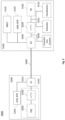
- Figure 2 schematically illustrates an example of a network system 2000 according to another embodiment of the present disclosure.
- the network system 2000 may comprise a network node 2100 which is typically located at the operator side and a terminal node (or an end-user device) 2200 which is typically located at the customer premises.
- the network node 2100 may be a DPU.
- the network node 2100 and the terminal node 2200 may be coupled (or connected) via a transmission line 2300, such as an xDSL subscriber line.
- the transmission line 2300 may be used both for exchanging data signals between the network node 2100 and the terminal node 2200 and for delivering power from the terminal node 2200 (or particularly from a power supply unit 2250 of the terminal node 2200) to the network node 2100.
- the power supply unit 2250 may correspond to an implementation of the apparatus/power supply unit 1250 as shown in Figures 1a and 1b .
- such power supplying from the customer side to the network side may be referred to as the RPF.
- the terminal node 2200 may comprise a PSE 2202 configured for injecting the power into the transmission line 2300 via a PS 2201.
- the terminal node 2200 may further comprise an xDSL Network Termination Equipment, hereafter abbreviated in this document by NTE 2203 configured for communicating xDSL broadband signals with the network node 2100 over the transmission line 2300.
- the PS 2201 may then be further configured to separate the power and the xDSL broadband signals.
- the power supply unit 2250 is integrated in the terminal node 2200, in some other cases, the power supply unit 2250 may be implemented as a standalone device (or apparatus).
- the terminal node 2200 may comprise any further suitable component and/or circuitry, depending on various circumstances or requirements.
- the terminal node may optionally comprise a backup power source for providing backup power in case of a power failure condition; or a power control unit (or circuitry) for controlling the power management behavior, e.g., during the start-up and operational phases.
- the network node 2100 may comprise a PE 2102 coupled to the transmission line 2300 with a PS 2101 configured for extracting the power delivered from (the power supply unit 2250 of) the terminal node 2200.
- the network node 2100 may also comprise an xDSL NTE 2103 configured for communicating xDSL broadband signals with the terminal node 2200 over the transmission line 2300 with the help of the PS 2101.
- the network node may further comprise means 2110 for performing the line measurement MELT.
- the present disclosure proposes a simple mechanism, driven by the network node 2100 (e.g., a DPU), to disconnect (and optionally reconnect) the PSE 2202 or the power supply unit 2250 from the transmission line 2300, such that a MELT measurement can be executed by the MELT block 2110 (e.g., implemented as a suitable testing/measurement circuitry) of the network node 2100.
- the network node 2100 e.g., a DPU
- the MELT block 2110 e.g., implemented as a suitable testing/measurement circuitry
- the network node 2100 shall instruct the PSE 2202 (or particularly the power supply unit 2250) to cease providing power and disconnect itself from the transmission line 2300 and possibly to provide a sufficiently high impedance to the line 2300, such that the PSE 2202 (or the power supply unit 2250) will not (significantly) impact the capacitance, resistance and foreign voltage measurements by the MELT circuitry 2110 within the network node 2100.
- the terminal node 2200 may further comprise a PSE disconnect block 2220, whilst the network node 2100 may further comprise a detection signature block 2121, a classification signature block 2122 and a PE disconnect block 2120.
- the detection and classification signature blocks 2121 and 2122 may be configured to generate predefined detection and classification signatures respectively, as illustrated above.
- the PSE disconnect block 2220 may be configured to disconnect the power supply unit 2250 from the transmission line 2300; and the PE disconnect block 2120 may be configured to disconnect (or block) the PE 2102 and/or possibly the detection and classification signatures 2121 and 2122 from the transmission line 2300, depending on various circumstances (such as the specific phase of operation of the network system).
- the network node 2100 When the network node 2100 wants to perform a MELT measurement (e.g., either periodically or being triggered), the network node 2100, particularly the PE disconnect block 2120 may be operated (or configured) to disconnect the respective block(s) of the network node 2100, depending on which operation phase the network system is at. For instance, if the terminal node 2200 (or the power supply unit 2250) is not yet started up, or is starting up, the PE disconnect block 2120 may be configured to disable the detection and/or classification signature 2121 and 2122 on the line 2300. Consequently, the disconnection of the detection/classification signatures 2121 and 2122 can prevent the power supply unit 2250 from starting up.
- the PE disconnect block 2120 may be operated (or configured) to disconnect the respective block(s) of the network node 2100, depending on which operation phase the network system is at. For instance, if the terminal node 2200 (or the power supply unit 2250) is not yet started up, or is starting up, the PE disconnect block 2120 may be
- the PE disconnect block 2120 may be configured to completely or partially block the PE 2102 from drawing (or extracting) power from the power supply unit 2250. That is, for instance, the network node 2100, particularly the PE 2102 therein, may be configured to draw no current or a current below a predefined current limit from the power supply unit 2250.
- the predefined limit may be a Maintain Power Signature current.
- the terminal node 2200 (or particularly the power supply unit 2250) may be configured to disconnect itself from the transmission line 2300, e.g., by the PSE disconnect block 2220 after detecting either an invalid or absent detection and/or classification signature, during the start-up flow of the power supply unit 2250; or a power violation (e.g., violation of the Maintain Power Signature), during normal operations of the power supply unit 2250 when the power supply unit 2250 is already supplying power to the network node 2100.
- a power violation e.g., violation of the Maintain Power Signature
- the power supply unit 2250 or the terminal node 2200 may be, e.g., with the help of additional monitoring means (such as the monitoring means 1220 in Figure 1b ), further configured to monitor at least one electrical parameter of the transmission line 2300, such as a quantity indicative of an impedance, a current, or the like.
- additional monitoring means such as the monitoring means 1220 in Figure 1b
- the power supply unit 2250 may be disconnected from the transmission line 2300 for a certain (e.g., predefined) time period (which may be referred to as MELT wait time), e.g., 20 seconds.
- a certain time period (which may be referred to as MELT wait time), e.g., 20 seconds.
- the power supply unit 2250 may be configured to reconnect itself back to the line 2300. As will be appreciated by the skilled person, such reconnection may require the power supply unit 2250 to for example perform the start-up procedure (e.g., the MDSU start-up protocol) again before being able to provide power supply to the network node 2100.
- the start-up procedure e.g., the MDSU start-up protocol
- the network node 2100 may make use of this MELT wait time period to perform the MELT measurement(s), or any other suitable operation if necessary.
- the network node 2100 may detect the disconnection of the power supply unit 2250 by monitoring the line voltage or any other suitable quantity (e.g., a current or a resistance) indicative of the line voltage.
- the network node may also discharge any residual (e.g., RPF) voltage on the transmission line 2300 before the MELT measurements are to be performed, to make sure that the measurement results are reliable and possibly not affected by any residual voltage on the line 2300.
- any residual e.g., RPF
- the network node e.g., the DPU
- the network node typically requires power. Since the supply power is stopped after the power supply unit 2250 being disconnected, the network node may try to use power either from another transmission line or from a set of transmission lines which reverse power the network node. Or when only the line, which is to be tested, is powering the network node, the network node may rely on (e.g., internal) back-up power to perform the MELT measurement. To reduce the power demand, the network node could also cease providing xDSL service to the line under test.
- the xDSL line could be used as a communication channel for the DPU to request the power supply unit to disconnect itself from the twisted pair. This requires that the xDSL line is operational, which could not always be the case when MELT would be used to debug a field issue.
- a communication channel is not present.
- the present disclosure does not rely on DSL functionality. The communication for disconnect and reconnect from the DPU to the PSE is not using communication functions of DSL.
- the present disclosure is also applicable for a two-box scenario, where power supply unit and NTE are in separate boxes at customer premises, without active communication between this power supply unit and NTE.
- communication for requesting a disconnect could also be done by using the DSL communication, e.g. over the OAM (Operation and Maintenance) channel to the NTE at customer premises.
- the NTE could in this case communicate to the power supply unit to disconnect from the line.
- This requires the functionality of the DSL communication to be active, which is not always present when there is an issue with the communication line.
- the present disclosure can be used for a one-box scenario.
- Figure 3 schematically illustrates an example of a network system 3000 according to another embodiment of the present disclosure.
- identical or like reference numbers in Figure 3 indicate identical or like elements in the network system 2000 as shown in Figure 2 , such that repeated description thereof may be omitted for reasons of conciseness.
- the network system 3000 of Figure 3 may comprise an xDSL NTE 3203, a PSE 3202, a PSE disconnect block 3220 and a PS 3201 in the terminal node 3200 at the customer premises side; and a MELT block 3110, an xDSL NTE 3103, a PS 3101, a PE disconnect block 3120, a PE 3102, a detection signature block 3121 and a classification block 3122 in the network node 3100 at the network side.
- the PSE 3202 and the PSE disconnect block 3220 may be comprised in a power supply unit 3250, similar to the power supply unit 2250 of Figure 2 .
- the network node 3100 of Figure 3 may further comprise an additional excessive line current block 3130.
- the PSE disconnect block 3220 may be configured to provide the disconnection of the power supply unit 3250 from the transmission line 3300 and may be operated as described above.
- the PE disconnect block 3120 may be configured to provide the disconnection of the PE 3102, and/or the detection/classification signatures 3121 and 3122 from the transmission line 3300, and may be operated when a MELT measurement is started, to avoid impact on the MELT measurement.
- the excessive line current block 3130 may be configured to provide the required excessive line current to force the power supply unit 3250to be disconnected from the transmission line 3300.
- the network node 3100 when the network node 3100 wants to perform a MELT measurement (e.g., either periodically or being triggered), the network node 3100, particularly the PE disconnect block 3120 therein may be operated (or configured) to disable the detection and/or classification signature 3121 and 3122 on the line 3300, particularly if the power supply unit 3250is not yet started up, or is starting up.
- a MELT measurement e.g., either periodically or being triggered
- the network node 3100, particularly the PE disconnect block 3120 therein may be operated (or configured) to disable the detection and/or classification signature 3121 and 3122 on the line 3300, particularly if the power supply unit 3250is not yet started up, or is starting up.
- the network node 3100 may be configured to draw an excessive line current from the power supply unit 3250, violating a (second) predefined power limit of the power supply unit 3250.
- the (second) predefined power limit may be a Continuous Output Power limit of the power supply unit 3250. That is, for instance, the network node 3100, particularly the excessive line current block 3130, together with the PE 3102, may be configured to draw a current above the (second) predefined limit (e.g., the Continuous Output Power) from the power supply unit 3250.
- the terminal node 3200 may be configured to disconnect itself from the transmission line 3300 for a certain time period (which may be referred to as MELT wait time), e.g., 20 seconds, after detecting either an invalid or absent detection and/or classification signature, during the start-up phase of the power supply unit 3250; or a power violation (e.g., violation of the Continuous Output Power), during normal operational phase of the power supply unit 3250when the power supply unit 3250 is already supplying power to the network node 3100.
- a power violation e.g., violation of the Continuous Output Power
- the power supply unit 3250 (or the terminal node 3200) may be configured to reconnect itself back to the line 3300. As will be appreciated by the skilled person, such reconnection may require the power supply unit 3250to for example perform the start-up procedure (e.g., the MDSU start-up protocol) before being able to provide power supply to the network node 3100 again.
- the start-up procedure e.g., the MDSU start-up protocol
- the network node 3100 may make use of this MELT wait time period to perform the MELT measurement(s), or any other suitable operation if necessary.
- the network node 3100 may detect the disconnection of the power supply unit 3250by monitoring the line voltage or any other suitable quantity (e.g., a current or a resistance) indicative of the line voltage.
- the network node 3100 may also discharge any residual RPF voltage on the transmission line 3300 before executing the MELT measurements, to assure reliable measurement results.
- the maximum allowed time for a single or combined sets of MELT measurements may be set to a relatively long period of time (e.g., 20 seconds or more) for a network node (e.g., a DPU) to be without power supplied from the PSE of the line under test.
- a network node e.g., a DPU
- the PSE may reconnect itself back to the line and to restart powering the DPU, even before expiry of the predefined period of disconnection time.
- such reconnection of the PSE to the transmission line may be performed bypassing the MDSU start-up protocol.
- Figure 4 schematically illustrates an example of a network system 4000 according to an embodiment of the present disclosure.
- identical or like reference numbers in Figure 4 indicate identical or like elements in the network system 2000 as shown in Figure 2 , such that repeated description thereof may be omitted for reasons of conciseness.
- the reconnect detection block 4230 may be configured for continued monitoring the electrical parameters (e.g., the line voltage) of the transmission line 4300, when the power supply unit 4250is disconnected.
- the reconnect detection block 4230 may be configured to reconnect the power supply unit 4250 back to the transmission line 4300 upon detection (or decoding) of a predefined line condition.
- the predefined line condition may comprise a specific voltage signaling (e.g., generated using the MELT circuitry) which may include an AC part and a DC part.
- the AC part may convey a (supported) power class of the network node; while the DC part may be used to detected off-hook phones on the twisted pair. That is to say, by decoding (or detecting) the AC signal, the power supply unit 4250 may verify that there is a DPU (network node 4100) present and that the PSE RPF power class matches the DPU RPF power class.
- the power supply unit 4250 may verify that there is a DPU (network node 4100) present and that the PSE RPF power class matches the DPU RPF power class.
- the power supply unit 4250 may verify: 1) absence of a short, as short will lower the DC voltage; 2) absence of an off-hook phone, as an off-hook phone will lower the DC voltage; and 3) absence of an open circuit, otherwise there would not be a DC voltage at the PSE side. More particularly, the DC part may be set on the transmission line with a high output impedance, such that any off-hook phone would lower the voltage on the line.
- the power supply unit 4250 may be configured to be reconnected back to the transmission line 4300 and possibly to (e.g., immediately) power the network node 4100 upon decoding a supported (e.g., RPF) power class from the AC signal and detecting a predetermined DC voltage.
- the DC voltage may be predetermined to be sufficiently high (e.g., 50 or 60 V), for indicating absence of an off-hook phone.
- any other suitable signals or combination thereof may be used to be defined as the to-be-detected line condition, such that it can be easily detected by the power supply unit 4250 (particularly by the reconnect detection block 4230) and reliably considered as a trigger for reconnecting to the transmission line 4300.
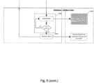
- Figure 5 schematically illustrates an example of a flow chart according to an embodiment of the present disclosure in accordance with the MDSU start-up flow for PSE and DPU as given in TS 101 548-1.
- Figure 5 schematically shows a MDSU start-up flow that may be applied in combination with MELT functionality between a PSE (or particularly a power supply unit) at the customer premises side and a DPU at the operator side.
- the "PSE” in Figure 5 may be considered to correspond to the power supply unit 2250 or 3250 (comprising the respective PSE 2202 or 3202 and PSE disconnect block 2220 or 3220) in Figure 2 or 3 ; and the "DPU” in Figure 5 may correspond to the respective network node 2100 or 3100 in Figure 2 or 3 .
- the white-colored blocks indicate the behavior in the normal mode (or in other words, no need for MELT measurements); while the striped blocks indicate the behavior for initializing or triggering MELT measurements as illustrated above for Figures 2 and 3 .
- the flow may start with power supply unit being in the idle (or power off) state in 5000.
- the power supply unit may go through a process 5010 for detecting and evaluating the detection signature as illustrated above.
- the DPU (or the network node) on the other side of the transmission line may be configured to behave in 5110 accordingly depending on whether MELT measurements are to be performed or not. For instance, in normal modes where no MELT measurement is expected, the DPU may be configured to signal the detection signature as defined; whilst if a MELT measurement is to be executed, the DPU may be configured to refrain from signaling any valid detection signature, as illustrated above.
- the DPU may be configured to behave in 5120 accordingly depending on whether MELT measurements are to be performed or not. Particularly, in normal modes where no MELT measurement is expected, the DPU may be configured to signal the classification signature as defined; whilst if a MELT measurement is to be executed, the DPU may be configured to refrain from signaling any valid classification signature, as illustrated above.
- the power supply unit may be configured to start providing power in 5030 to the DPU and enter the normal operational phase.
- the power supply unit may be configured to cease providing power to the DPU in 5050.
- the power supply unit may be configured to be disconnected in 5060 from the transmission line if any of the erroneous conditions illustrated above is detected.
- the power supply unit may be configured to be disconnected for a period of time e.g. according to a MELT wait timer in 5070; and upon expiry of the timer, the power supply unit may be configured to reconnect itself back to the transmission line in 5080 and return to the idle state of 5000.
- Figure 6 schematically illustrates an example of a flow chart according to another embodiment of the present disclosure, also in accordance with the MDSU start-up flow for PSE and DPU as given in TS 101 548-1.
- identical or like reference numbers in Figure 6 indicate identical or like elements in the flow chart as shown in Figure 5 , such that repeated description thereof may be omitted for reasons of conciseness.
- Figure 6 additionally shows a reconnection process 6090 wherein the power supply unit (e.g., the power supply unit 4250 of Figure 4 ) may be configured to reconnect itself back to the transmission line if a predefined line condition is detected, as illustrated above in details. Configured as such, the power supply unit may not need to wait till the expiry of the predefined MELT wait time and may be capable of being (actively) reconnected if certain line condition(s) is fulfilled, thereby improving the overall efficiency of the network system.
- the power supply unit e.g., the power supply unit 4250 of Figure 4
- the power supply unit may not need to wait till the expiry of the predefined MELT wait time and may be capable of being (actively) reconnected if certain line condition(s) is fulfilled, thereby improving the overall efficiency of the network system.
- the disclosed example embodiments can be implemented in many ways using hardware and/or software configurations.
- the disclosed embodiments may be implemented using dedicated hardware and/or hardware in association with software executable thereon.
- the components and/or elements in the figures are examples only and do not limit the scope of use or functionality of any hardware, software in combination with hardware, firmware, embedded logic component, or a combination of two or more such components implementing particular embodiments of this disclosure.
- Coupled and “couplable” should not be interpreted as being restricted to direct connections only.
- scope of the expression “a device A coupled to a device B” should not be limited to devices or systems wherein an output of device A is directly connected to an input of device B, and/or vice-versa. It means that there exists a path between an output of A and an input of B, and/or vice-versa, which may be a path including other devices or means.
- circuitry may refer to one or more or all of the following: (a) hardware-only circuit implementations (such as implementations in only analog and/or digital circuitry) and (b) combinations of hardware circuits and software, such as (as applicable): (i) a combination of analog and/or digital hardware circuit(s) with software/firmware and (ii) any portions of hardware processor(s) with software (including digital signal processor(s)), software, and memory(ies) that work together to cause an apparatus, such as a server or an user device, to perform various functions) and (c) hardware circuit(s) and or processor(s), such as a microprocessor(s) or a portion of a microprocessor(s), that requires software (e.g., firmware) for operation, but the software may not be present when it is not needed for operation.
- hardware-only circuit implementations such as implementations in only analog and/or digital circuitry
- combinations of hardware circuits and software such as (as applicable): (i) a combination of analog and/or digital hardware circuit(
- circuitry also covers an implementation of merely a hardware circuit or processor (or multiple processors) or portion of a hardware circuit or processor and its (or their) accompanying software and/or firmware.
Landscapes
- Engineering & Computer Science (AREA)
- Computer Networks & Wireless Communication (AREA)
- Signal Processing (AREA)
- Power Engineering (AREA)
- Environmental & Geological Engineering (AREA)
- Monitoring And Testing Of Exchanges (AREA)
- Cable Transmission Systems, Equalization Of Radio And Reduction Of Echo (AREA)
- Devices For Supply Of Signal Current (AREA)
Claims (16)
- Netzwerkknoten (1100, 2100, 3100, 4100), der via eine Übertragungsleitung (1300, 2300, 3300, 4300) an eine Einrichtung (1250, 2250, 3250, 4250) koppelbar ist, wobei der Netzwerkknoten (1100, 2100, 3100, 4100) Mittel für Folgendes umfasst:- Empfangen (1110) einer Versorgungsleistung via die Übertragungsleitung (1300, 2300, 3300, 4300) von der Einrichtung (1250, 2250, 3250, 4250);- Durchführen (1120) einer Leitungsmessung auf der Übertragungsleitung (1300, 2300, 3300, 4300) und- Signalisieren (1130) an die Einrichtung (1250, 2250, 3250, 4250), dass sie sich von der Übertragungsleitung (1300, 2300, 3300, 4300) trennen soll,wobei die Mittel ferner dazu ausgelegt sind, die Leitungsmessung auf der Übertragungsleitung (1300, 2300, 3300, 4300) während einer Zeitperiode durchzuführen, in der die Einrichtung (1250, 2250, 3250, 4250) von der Übertragungsleitung (1300, 2300, 3300, 4300) getrennt ist, wobei die Mittel ferner zu Folgendem ausgelegt sind:Anwenden einer ungültigen oder nicht vordefinierten Signatur auf die Übertragungsleitung (1300, 2300, 3300, 4300) undVerletzen einer Leistungseinschränkung zum Entnehmen einer Versorgungsleistung, die von der Einrichtung (1250, 2250, 3250, 4250) bereitgestellt wird.
- Netzwerkknoten nach Anspruch 1, wobei die Mittel ferner dazu ausgelegt sind, die ungültige oder nicht vordefinierte Signatur vor oder während einer Startphase des Empfangs der Versorgungsleistung von der Einrichtung (1250, 2250, 3250, 4250) anzuwenden.
- Netzwerkknoten nach Anspruch 1, wobei die Mittel ferner dazu ausgelegt sind, die Verletzung der Leistungseinschränkung durch Entnehmen eines Stroms unter oder über einem vordefinierten Grenzwert aus der Übertragungsleitung (1300, 2300, 3300, 4300) durchzuführen, und wobei die Verletzung der Leistung während einer Betriebsphase des Knotens und des Empfangs der Versorgungsleistung von der Einrichtung (1250, 2250, 3250, 4250) durchgeführt wird.
- Netzwerkknoten nach einem der Ansprüche 1 bis 3, wobei die Mittel ferner dazu ausgelegt sind, durch Überwachen einer Menge, die eine Spannung auf der Übertragungsleitung (1300, 2300, 3300, 4300) anzeigt, eine Trennung der Einrichtung (1250, 2250, 3250, 4250) von der Übertragungsleitung (1300, 2300, 3300, 4300) zu detektieren.
- Netzwerkknoten nach einem der Ansprüche 1 bis 4, wobei die Mittel ferner dazu ausgelegt sind, der getrennten Einrichtung (1250, 2250, 3250, 4250) via die Übertragungsleitung (1300, 2300, 3300, 4300) zu signalisieren, dass sich die Einrichtung (1250, 2250, 3250, 4250) erneut mit der Übertragungsleitung (1300, 2300, 3300, 4300) verbinden soll.
- Netzwerkknoten nach Anspruch 5, wobei die Mittel ferner dazu ausgelegt sind, der Einrichtung (1250, 2250, 3250, 4250) zu signalisieren, dass sie sich durch Folgendes erneut mit der Übertragungsleitung (1300, 2300, 3300, 4300) verbinden soll:
Anlegen von mindestens einem eines AC-Signals oder einer vorbestimmten DC-Spannung an die Übertragungsleitung (1300, 2300, 3300, 4300). - Einrichtung (1250, 2250, 3250, 4250), die via eine Übertragungsleitung (1300, 2300, 3300, 4300) an einen Netzwerkknoten (1100, 2100, 3100, 4100) koppelbar ist, wobei die Einrichtung (1250, 2250, 3250, 4250) Mittel für Folgendes umfasst:- Bereitstellen (1210) einer Versorgungsleistung für den Netzwerkknoten (1100, 2100, 3100, 4100);- Überwachen (1220) mindestens eines elektrischen Parameters der Übertragungsleitung (1300, 2300, 3300, 4300) und- Trennen (1230) der Einrichtung (1250, 2250, 3250, 4250) von der Übertragungsleitung (1300, 2300, 3300, 4300), wenn eine vorbestimmte Leitungsbedingung oder eine Leistungsverletzung detektiert wird, derart, dass der Netzwerkknoten (1100, 2100, 3100, 4100) eine Messung auf der Übertragungsleitung (1300, 2300, 3300, 4300) durchführen kann,- wobei die vorbestimmte Leitungsbedingung eine ungültige oder fehlende vordefinierte Signatur des Netzwerkknotens (1100, 2100, 3100, 4100) umfasst und wobei die Mittel ferner dazu ausgelegt sind, die vorbestimmte Leitungsbedingung vor oder während einer Startphase vor der Bereitstellung von Versorgungsleistung für den Netzwerkknoten (1100, 2100, 3100, 4100) zu detektieren.
- Einrichtung nach Anspruch 7, wobei die Mittel ferner für Folgendes ausgelegt sind
Überwachen des mindestens einen elektrischen Parameters der Übertragungsleitung (1300, 2300, 3300, 4300) durch Folgendes:Anlegen einer vorbestimmten Spannung an die Übertragungsleitung (1300, 2300, 3300, 4300) undMessen einer Menge, die eine Impedanz oder einen Strom auf der Übertragungsleitung (1300, 2300, 3300, 4300) anzeigt. - Einrichtung nach einem der vorhergehenden Ansprüche 7 oder 8, wobei die Leistungsverletzung einen Strom, der durch den Netzwerkknoten (1100, 2100, 3100, 4100) entnommen wird, unter oder über einem vordefinierten Grenzwert umfasst und die Leistungsverletzung während einer Betriebsphase der Einrichtung (1250, 2250, 3250, 4250) und der Bereitstellung einer Versorgungsleistung für den Netzwerkknoten (1100, 2100, 3100, 4100) detektiert wird.
- Einrichtung nach einem der vorhergehenden Ansprüche 7 bis 9, wobei die Mittel ferner dazu ausgelegt sind, die Einrichtung (1250, 2250, 3250, 4250) durch Folgendes von der Übertragungsleitung (1300, 2300, 3300, 4300) zu trennen:Beenden der Bereitstellung einer Versorgungsleistung für den Netzwerkknoten (1100, 2100, 3100, 4100) undBereitstellen einer ausreichend hohen Impedanz auf der Übertragungsleitung (1300, 2300, 3300, 4300), um die Leitungsmessung nicht zu beeinträchtigen.
- Einrichtung nach einem der vorhergehenden Ansprüche 7 bis 10, wobei die Mittel ferner dazu ausgelegt sind, die Einrichtung (1250, 2250, 3250, 4250) für eine vordefinierte Zeitperiode von der Übertragungsleitung (1300, 2300, 3300, 4300) zu trennen und nach Ablauf der vordefinierten Zeitperiode erneut mit der Übertragungsleitung (1300, 2300, 3300, 4300) zu verbinden.
- Einrichtung nach einem der vorhergehenden Ansprüche 7 bis 11, wobei die Mittel ferner zu Folgendem ausgelegt sind:Überwachen von mindestens einem zweiten elektrischen Parameter der Übertragungsleitung (1300, 2300, 3300, 4300), nachdem die Einrichtung (1250, 2250, 3250, 4250) von der Übertragungsleitung (1300, 2300, 3300, 4300) getrennt wurde; underneutes Verbinden der Einrichtung (1250, 2250, 3250, 4250) mit der Übertragungsleitung (1300, 2300, 3300, 4300), wenn durch Überwachen von mindestens einem zweiten elektrischen Parameter der Übertragungsleitung (1300, 2300, 3300, 4300) eine weitere vorbestimmte Leitungsbedingung von der Einrichtung (1250, 2250, 3250, 4250) detektiert wird,wobei die weitere vorbestimmte Leitungsbedingung mindestens eines von einem AC-Signal oder einer vorbestimmten DC-Spannung umfasst.
- Endbenutzervorrichtung (1200, 2200, 3200, 4200), die eine Einrichtung (1250, 2250, 3250, 4250) nach einem der Ansprüche 7 bis 12 umfasst, wobei die Endbenutzervorrichtung ferner Mittel (1240) umfasst, die zum Kommunizieren via die Übertragungsleitung (1300, 2300, 3300, 4300) mit einem Netzwerkknoten (1100, 2100, 3100, 4100) eines Kommunikationsnetzwerks ausgelegt sind.
- Netzwerkknoten nach einem der Ansprüche 1 bis 6, der Mittel (1140) zum Kommunizieren mit der Endbenutzervorrichtung (1200, 2200, 3200, 4200) nach Anspruch 13 über die Übertragungsleitung (1300, 2300, 3300, 4300) via das Kommunikationsnetzwerk umfasst.
- Verfahren zum Betreiben eines Netzwerkknotens (1100, 2100, 3100, 4100), der via eine Übertragungsleitung (1300, 2300, 3300, 4300) an eine Einrichtung (1250, 2250, 3250, 4250) koppelbar ist, wobei das Verfahren Folgendes umfasst:- Empfangen einer Versorgungsleistung via die Übertragungsleitung (1300, 2300, 3300, 4300) von der Einrichtung (1250, 2250, 3250, 4250);- Durchführen einer Leitungsmessung auf der Übertragungsleitung (1300, 2300, 3300, 4300) und- Signalisieren an die Einrichtung (1250, 2250, 3250, 4250), dass sie sich von der Übertragungsleitung (1300, 2300, 3300, 4300) trennen soll,wobei die Leitungsmessung auf der Übertragungsleitung (1300, 2300, 3300, 4300) während einer Zeitperiode durchgeführt wird, in der die Einrichtung (1250, 2250, 3250, 4250) von der Übertragungsleitung (1300, 2300, 3300, 4300) getrennt ist, wobei das Verfahren ferner Folgendes umfasst:Anwenden einer ungültigen oder nicht vordefinierten Signatur auf die Übertragungsleitung (1300, 2300, 3300, 4300) undVerletzen einer Leistungseinschränkung zum Entnehmen einer Versorgungsleistung, die von der Einrichtung (1250, 2250, 3250, 4250) bereitgestellt wird.
- Verfahren zum Betreiben einer Einrichtung (1250, 2250, 3250, 4250), die via eine Übertragungsleitung (1300, 2300, 3300, 4300) an einen Netzwerkknoten (1100, 2100, 3100, 4100) koppelbar ist, wobei das Verfahren Folgendes umfasst:- Bereitstellen einer Versorgungsleistung für den Netzwerkknoten (1100, 2100, 3100, 4100);- Überwachen mindestens eines elektrischen Parameters der Übertragungsleitung (1300, 2300, 3300, 4300) und- Trennen der Einrichtung (1250, 2250, 3250, 4250) von der Übertragungsleitung (1300, 2300, 3300, 4300), wenn eine vorbestimmte Leitungsbedingung oder eine Leistungsverletzung detektiert wird, derart, dass der Netzwerkknoten (1100, 2100, 3100, 4100) eine Messung auf der Übertragungsleitung (1300, 2300, 3300, 4300) durchführen kann,- wobei die vorbestimmte Leitungsbedingung eine ungültige oder fehlende vordefinierte Signatur des Netzwerkknotens (1100, 2100, 3100, 4100) umfasst und wobei das Verfahren ferner das Detektieren der vorbestimmten Leitungsbedingung vor oder während einer Startphase vor der Bereitstellung einer Versorgungsleistung für den Netzwerkknoten (1100, 2100, 3100, 4100) umfasst.
Priority Applications (3)
| Application Number | Priority Date | Filing Date | Title |
|---|---|---|---|
| EP20154725.4A EP3859984B1 (de) | 2020-01-30 | 2020-01-30 | Melt bei rückleistungsspeisung |
| US17/159,933 US11444659B2 (en) | 2020-01-30 | 2021-01-27 | Melt with reverse power feed |
| CN202110118201.1A CN113206766A (zh) | 2020-01-30 | 2021-01-28 | 具有反向电源馈送的melt |
Applications Claiming Priority (1)
| Application Number | Priority Date | Filing Date | Title |
|---|---|---|---|
| EP20154725.4A EP3859984B1 (de) | 2020-01-30 | 2020-01-30 | Melt bei rückleistungsspeisung |
Publications (2)
| Publication Number | Publication Date |
|---|---|
| EP3859984A1 EP3859984A1 (de) | 2021-08-04 |
| EP3859984B1 true EP3859984B1 (de) | 2023-05-17 |
Family
ID=69423072
Family Applications (1)
| Application Number | Title | Priority Date | Filing Date |
|---|---|---|---|
| EP20154725.4A Active EP3859984B1 (de) | 2020-01-30 | 2020-01-30 | Melt bei rückleistungsspeisung |
Country Status (3)
| Country | Link |
|---|---|
| US (1) | US11444659B2 (de) |
| EP (1) | EP3859984B1 (de) |
| CN (1) | CN113206766A (de) |
Family Cites Families (10)
| Publication number | Priority date | Publication date | Assignee | Title |
|---|---|---|---|---|
| JP3730146B2 (ja) * | 2001-08-29 | 2005-12-21 | 日本電信電話株式会社 | 網終端装置、網終端装置における消費電力削減方法、記録媒体及びプログラム |
| CA2519617C (en) * | 2003-02-27 | 2008-04-15 | Nec Corporation | A multiplexer for ethernet networks |
| JP2012186636A (ja) * | 2011-03-04 | 2012-09-27 | Nec Corp | 光ファイバ伝送システムにおける出力自動低減制御方式及び方法 |
| CN202495703U (zh) * | 2012-03-22 | 2012-10-17 | 杭州申发电气有限公司 | 预检线路故障的断路器 |
| EP2816758A1 (de) * | 2013-06-17 | 2014-12-24 | Alcatel Lucent | Verfahren zum Umgang mit anomalen Zuständen in einem Rückleistungsnetzwerk und Strominjektor zur Verwendung in solch einem Verfahren |
| US10110755B2 (en) * | 2013-12-31 | 2018-10-23 | British Telecommunications Public Limited Company | Method and apparatus for use in supplying power over a telephone line |
| EP3086507A1 (de) * | 2015-04-24 | 2016-10-26 | Thomson Licensing | Verfahren zum betrieb einer verteilungspunkteinheit, entsprechende verteilungspunkteinheit und cpe-vorrichtung |
| EP3099005B1 (de) * | 2015-05-26 | 2019-12-25 | Alcatel Lucent | Bereitstellung neuer breitbandkommunikation durch umgekehrte stromversorgung |
| FR3055751B1 (fr) * | 2016-09-02 | 2018-09-21 | Inst Supergrid | Procede de pilotage d’une installation permettant le transport de courant continu dans un reseau tout en protegeant ledit reseau vis a vis d’un defaut de court-circuit |
| CN109687384B (zh) * | 2018-12-29 | 2020-05-08 | 苏州路之遥科技股份有限公司 | 一种基于计算无功功率的大功率切除保护和复位方法 |
-
2020
- 2020-01-30 EP EP20154725.4A patent/EP3859984B1/de active Active
-
2021
- 2021-01-27 US US17/159,933 patent/US11444659B2/en active Active
- 2021-01-28 CN CN202110118201.1A patent/CN113206766A/zh active Pending
Also Published As
| Publication number | Publication date |
|---|---|
| US20210242904A1 (en) | 2021-08-05 |
| US11444659B2 (en) | 2022-09-13 |
| EP3859984A1 (de) | 2021-08-04 |
| CN113206766A (zh) | 2021-08-03 |
Similar Documents
| Publication | Publication Date | Title |
|---|---|---|
| EP3090532B1 (de) | Vorrichtung zur verwendung bei der stromversorgung über eine telefonleitung | |
| KR101742417B1 (ko) | 역방향 전력 네트워크에서 이상 상태를 처리하는 방법, 및 그 방법에 사용하기 위한 파워 인젝터 | |
| US6986071B2 (en) | Detecting network power connection status using AC signals | |
| US8818192B1 (en) | Optical network unit with redundant reverse powering from customer premises equipment with alarm fault discrimination indicative for power fault condition | |
| US10476685B2 (en) | Provisioning of new broadband communication services using reverse power feeding | |
| US7814342B2 (en) | System and method for communication using an AC signal from a powered device | |
| EP1889081A2 (de) | Verfahren und vorrichtung zur erkennung und behebung von defekten in einem inline-strom-fähigen ethernetsystem | |
| US10539994B2 (en) | Rapid resumption of a power supply via a data link after power outage | |
| EP3029881A1 (de) | Umgekehrtes stromversorgungsverfahren, umgekehrte stromversorgungsvorrichtung und system | |
| US5630058A (en) | Network connected device protection | |
| EP3859984B1 (de) | Melt bei rückleistungsspeisung | |
| WO2015175580A1 (en) | Apparatus and method for detection of off-hook phone in reverse power feeding architecture | |
| EP3544195B1 (de) | Systeme und verfahren zur automatisierten breitbandigen stromversorgung einer verteilstelleneinheit | |
| EP3197096B1 (de) | Verwendung von schnittstellen einer netzwerkzugangsvorrichtung | |
| EP1995844A9 (de) | Verfahren zur detektion der verbindung einer fernstromversorgung und netzbestromungsverfahren und system | |
| US20100226480A1 (en) | Method and apparatus for detecting long unterminated phone wiring loops | |
| GB2354906A (en) | Line testing arrangement |
Legal Events
| Date | Code | Title | Description |
|---|---|---|---|
| PUAI | Public reference made under article 153(3) epc to a published international application that has entered the european phase |
Free format text: ORIGINAL CODE: 0009012 |
|
| STAA | Information on the status of an ep patent application or granted ep patent |
Free format text: STATUS: THE APPLICATION HAS BEEN PUBLISHED |
|
| AK | Designated contracting states |
Kind code of ref document: A1 Designated state(s): AL AT BE BG CH CY CZ DE DK EE ES FI FR GB GR HR HU IE IS IT LI LT LU LV MC MK MT NL NO PL PT RO RS SE SI SK SM TR |
|
| STAA | Information on the status of an ep patent application or granted ep patent |
Free format text: STATUS: REQUEST FOR EXAMINATION WAS MADE |
|
| 17P | Request for examination filed |
Effective date: 20211011 |
|
| RBV | Designated contracting states (corrected) |
Designated state(s): AL AT BE BG CH CY CZ DE DK EE ES FI FR GB GR HR HU IE IS IT LI LT LU LV MC MK MT NL NO PL PT RO RS SE SI SK SM TR |
|
| GRAP | Despatch of communication of intention to grant a patent |
Free format text: ORIGINAL CODE: EPIDOSNIGR1 |
|
| STAA | Information on the status of an ep patent application or granted ep patent |
Free format text: STATUS: GRANT OF PATENT IS INTENDED |
|
| RIC1 | Information provided on ipc code assigned before grant |
Ipc: H04M 11/06 20060101ALI20220530BHEP Ipc: H04B 3/46 20150101AFI20220530BHEP |
|
| INTG | Intention to grant announced |
Effective date: 20220630 |
|
| GRAJ | Information related to disapproval of communication of intention to grant by the applicant or resumption of examination proceedings by the epo deleted |
Free format text: ORIGINAL CODE: EPIDOSDIGR1 |
|
| STAA | Information on the status of an ep patent application or granted ep patent |
Free format text: STATUS: REQUEST FOR EXAMINATION WAS MADE |
|
| GRAP | Despatch of communication of intention to grant a patent |
Free format text: ORIGINAL CODE: EPIDOSNIGR1 |
|
| STAA | Information on the status of an ep patent application or granted ep patent |
Free format text: STATUS: GRANT OF PATENT IS INTENDED |
|
| INTC | Intention to grant announced (deleted) | ||
| INTG | Intention to grant announced |
Effective date: 20221202 |
|
| GRAS | Grant fee paid |
Free format text: ORIGINAL CODE: EPIDOSNIGR3 |
|
| GRAA | (expected) grant |
Free format text: ORIGINAL CODE: 0009210 |
|
| STAA | Information on the status of an ep patent application or granted ep patent |
Free format text: STATUS: THE PATENT HAS BEEN GRANTED |
|
| AK | Designated contracting states |
Kind code of ref document: B1 Designated state(s): AL AT BE BG CH CY CZ DE DK EE ES FI FR GB GR HR HU IE IS IT LI LT LU LV MC MK MT NL NO PL PT RO RS SE SI SK SM TR |
|
| REG | Reference to a national code |
Ref country code: GB Ref legal event code: FG4D |
|
| REG | Reference to a national code |
Ref country code: CH Ref legal event code: EP |
|
| REG | Reference to a national code |
Ref country code: DE Ref legal event code: R096 Ref document number: 602020010869 Country of ref document: DE |
|
| REG | Reference to a national code |
Ref country code: IE Ref legal event code: FG4D |
|
| REG | Reference to a national code |
Ref country code: AT Ref legal event code: REF Ref document number: 1568820 Country of ref document: AT Kind code of ref document: T Effective date: 20230615 |
|
| REG | Reference to a national code |
Ref country code: LT Ref legal event code: MG9D |
|
| REG | Reference to a national code |
Ref country code: NL Ref legal event code: MP Effective date: 20230517 |
|
| REG | Reference to a national code |
Ref country code: AT Ref legal event code: MK05 Ref document number: 1568820 Country of ref document: AT Kind code of ref document: T Effective date: 20230517 |
|
| PG25 | Lapsed in a contracting state [announced via postgrant information from national office to epo] |
Ref country code: SE Free format text: LAPSE BECAUSE OF FAILURE TO SUBMIT A TRANSLATION OF THE DESCRIPTION OR TO PAY THE FEE WITHIN THE PRESCRIBED TIME-LIMIT Effective date: 20230517 Ref country code: PT Free format text: LAPSE BECAUSE OF FAILURE TO SUBMIT A TRANSLATION OF THE DESCRIPTION OR TO PAY THE FEE WITHIN THE PRESCRIBED TIME-LIMIT Effective date: 20230918 Ref country code: NO Free format text: LAPSE BECAUSE OF FAILURE TO SUBMIT A TRANSLATION OF THE DESCRIPTION OR TO PAY THE FEE WITHIN THE PRESCRIBED TIME-LIMIT Effective date: 20230817 Ref country code: NL Free format text: LAPSE BECAUSE OF FAILURE TO SUBMIT A TRANSLATION OF THE DESCRIPTION OR TO PAY THE FEE WITHIN THE PRESCRIBED TIME-LIMIT Effective date: 20230517 Ref country code: ES Free format text: LAPSE BECAUSE OF FAILURE TO SUBMIT A TRANSLATION OF THE DESCRIPTION OR TO PAY THE FEE WITHIN THE PRESCRIBED TIME-LIMIT Effective date: 20230517 Ref country code: AT Free format text: LAPSE BECAUSE OF FAILURE TO SUBMIT A TRANSLATION OF THE DESCRIPTION OR TO PAY THE FEE WITHIN THE PRESCRIBED TIME-LIMIT Effective date: 20230517 |
|
| PG25 | Lapsed in a contracting state [announced via postgrant information from national office to epo] |
Ref country code: RS Free format text: LAPSE BECAUSE OF FAILURE TO SUBMIT A TRANSLATION OF THE DESCRIPTION OR TO PAY THE FEE WITHIN THE PRESCRIBED TIME-LIMIT Effective date: 20230517 Ref country code: PL Free format text: LAPSE BECAUSE OF FAILURE TO SUBMIT A TRANSLATION OF THE DESCRIPTION OR TO PAY THE FEE WITHIN THE PRESCRIBED TIME-LIMIT Effective date: 20230517 Ref country code: LV Free format text: LAPSE BECAUSE OF FAILURE TO SUBMIT A TRANSLATION OF THE DESCRIPTION OR TO PAY THE FEE WITHIN THE PRESCRIBED TIME-LIMIT Effective date: 20230517 Ref country code: LT Free format text: LAPSE BECAUSE OF FAILURE TO SUBMIT A TRANSLATION OF THE DESCRIPTION OR TO PAY THE FEE WITHIN THE PRESCRIBED TIME-LIMIT Effective date: 20230517 Ref country code: IS Free format text: LAPSE BECAUSE OF FAILURE TO SUBMIT A TRANSLATION OF THE DESCRIPTION OR TO PAY THE FEE WITHIN THE PRESCRIBED TIME-LIMIT Effective date: 20230917 Ref country code: HR Free format text: LAPSE BECAUSE OF FAILURE TO SUBMIT A TRANSLATION OF THE DESCRIPTION OR TO PAY THE FEE WITHIN THE PRESCRIBED TIME-LIMIT Effective date: 20230517 Ref country code: GR Free format text: LAPSE BECAUSE OF FAILURE TO SUBMIT A TRANSLATION OF THE DESCRIPTION OR TO PAY THE FEE WITHIN THE PRESCRIBED TIME-LIMIT Effective date: 20230818 |
|
| PG25 | Lapsed in a contracting state [announced via postgrant information from national office to epo] |
Ref country code: FI Free format text: LAPSE BECAUSE OF FAILURE TO SUBMIT A TRANSLATION OF THE DESCRIPTION OR TO PAY THE FEE WITHIN THE PRESCRIBED TIME-LIMIT Effective date: 20230517 |
|
| PG25 | Lapsed in a contracting state [announced via postgrant information from national office to epo] |
Ref country code: SK Free format text: LAPSE BECAUSE OF FAILURE TO SUBMIT A TRANSLATION OF THE DESCRIPTION OR TO PAY THE FEE WITHIN THE PRESCRIBED TIME-LIMIT Effective date: 20230517 |
|
| PGFP | Annual fee paid to national office [announced via postgrant information from national office to epo] |
Ref country code: GB Payment date: 20231207 Year of fee payment: 5 |
|
| PG25 | Lapsed in a contracting state [announced via postgrant information from national office to epo] |
Ref country code: SM Free format text: LAPSE BECAUSE OF FAILURE TO SUBMIT A TRANSLATION OF THE DESCRIPTION OR TO PAY THE FEE WITHIN THE PRESCRIBED TIME-LIMIT Effective date: 20230517 Ref country code: SK Free format text: LAPSE BECAUSE OF FAILURE TO SUBMIT A TRANSLATION OF THE DESCRIPTION OR TO PAY THE FEE WITHIN THE PRESCRIBED TIME-LIMIT Effective date: 20230517 Ref country code: RO Free format text: LAPSE BECAUSE OF FAILURE TO SUBMIT A TRANSLATION OF THE DESCRIPTION OR TO PAY THE FEE WITHIN THE PRESCRIBED TIME-LIMIT Effective date: 20230517 Ref country code: EE Free format text: LAPSE BECAUSE OF FAILURE TO SUBMIT A TRANSLATION OF THE DESCRIPTION OR TO PAY THE FEE WITHIN THE PRESCRIBED TIME-LIMIT Effective date: 20230517 Ref country code: DK Free format text: LAPSE BECAUSE OF FAILURE TO SUBMIT A TRANSLATION OF THE DESCRIPTION OR TO PAY THE FEE WITHIN THE PRESCRIBED TIME-LIMIT Effective date: 20230517 Ref country code: CZ Free format text: LAPSE BECAUSE OF FAILURE TO SUBMIT A TRANSLATION OF THE DESCRIPTION OR TO PAY THE FEE WITHIN THE PRESCRIBED TIME-LIMIT Effective date: 20230517 |
|
| PGFP | Annual fee paid to national office [announced via postgrant information from national office to epo] |
Ref country code: FR Payment date: 20231212 Year of fee payment: 5 |
|
| REG | Reference to a national code |
Ref country code: DE Ref legal event code: R097 Ref document number: 602020010869 Country of ref document: DE |
|
| PLBE | No opposition filed within time limit |
Free format text: ORIGINAL CODE: 0009261 |
|
| STAA | Information on the status of an ep patent application or granted ep patent |
Free format text: STATUS: NO OPPOSITION FILED WITHIN TIME LIMIT |
|
| 26N | No opposition filed |
Effective date: 20240220 |
|
| PGFP | Annual fee paid to national office [announced via postgrant information from national office to epo] |
Ref country code: DE Payment date: 20231205 Year of fee payment: 5 |
|
| PG25 | Lapsed in a contracting state [announced via postgrant information from national office to epo] |
Ref country code: SI Free format text: LAPSE BECAUSE OF FAILURE TO SUBMIT A TRANSLATION OF THE DESCRIPTION OR TO PAY THE FEE WITHIN THE PRESCRIBED TIME-LIMIT Effective date: 20230517 |