EP3090532B1 - Vorrichtung zur verwendung bei der stromversorgung über eine telefonleitung - Google Patents
Vorrichtung zur verwendung bei der stromversorgung über eine telefonleitung Download PDFInfo
- Publication number
- EP3090532B1 EP3090532B1 EP14824064.1A EP14824064A EP3090532B1 EP 3090532 B1 EP3090532 B1 EP 3090532B1 EP 14824064 A EP14824064 A EP 14824064A EP 3090532 B1 EP3090532 B1 EP 3090532B1
- Authority
- EP
- European Patent Office
- Prior art keywords
- current
- power supply
- reverse power
- supply unit
- rate
- Prior art date
- Legal status (The legal status is an assumption and is not a legal conclusion. Google has not performed a legal analysis and makes no representation as to the accuracy of the status listed.)
- Active
Links
- 230000008859 change Effects 0.000 claims description 39
- RYGMFSIKBFXOCR-UHFFFAOYSA-N Copper Chemical compound [Cu] RYGMFSIKBFXOCR-UHFFFAOYSA-N 0.000 claims description 29
- 229910052802 copper Inorganic materials 0.000 claims description 29
- 239000010949 copper Substances 0.000 claims description 29
- 238000001514 detection method Methods 0.000 claims description 12
- 238000000034 method Methods 0.000 description 15
- 230000006399 behavior Effects 0.000 description 6
- 239000003990 capacitor Substances 0.000 description 6
- 230000008901 benefit Effects 0.000 description 5
- 230000006870 function Effects 0.000 description 5
- 230000003287 optical effect Effects 0.000 description 5
- 238000000605 extraction Methods 0.000 description 4
- 238000003780 insertion Methods 0.000 description 4
- 230000037431 insertion Effects 0.000 description 4
- 238000002955 isolation Methods 0.000 description 4
- 230000007246 mechanism Effects 0.000 description 4
- 230000009471 action Effects 0.000 description 3
- 238000013459 approach Methods 0.000 description 3
- 230000005540 biological transmission Effects 0.000 description 3
- 230000000903 blocking effect Effects 0.000 description 3
- 230000002452 interceptive effect Effects 0.000 description 2
- 238000012544 monitoring process Methods 0.000 description 2
- 239000013307 optical fiber Substances 0.000 description 2
- 230000008569 process Effects 0.000 description 2
- 230000000246 remedial effect Effects 0.000 description 2
- 230000011664 signaling Effects 0.000 description 2
- 230000007704 transition Effects 0.000 description 2
- 101150012579 ADSL gene Proteins 0.000 description 1
- 102100020775 Adenylosuccinate lyase Human genes 0.000 description 1
- 108700040193 Adenylosuccinate lyases Proteins 0.000 description 1
- 230000003466 anti-cipated effect Effects 0.000 description 1
- 230000009286 beneficial effect Effects 0.000 description 1
- 238000006243 chemical reaction Methods 0.000 description 1
- 238000004891 communication Methods 0.000 description 1
- 230000001419 dependent effect Effects 0.000 description 1
- 238000011161 development Methods 0.000 description 1
- 238000010586 diagram Methods 0.000 description 1
- 230000000694 effects Effects 0.000 description 1
- 230000005611 electricity Effects 0.000 description 1
- 239000000284 extract Substances 0.000 description 1
- 239000000835 fiber Substances 0.000 description 1
- 238000001914 filtration Methods 0.000 description 1
- 230000001939 inductive effect Effects 0.000 description 1
- 230000003993 interaction Effects 0.000 description 1
- 238000011835 investigation Methods 0.000 description 1
- 238000012423 maintenance Methods 0.000 description 1
- 230000008450 motivation Effects 0.000 description 1
- 238000012360 testing method Methods 0.000 description 1
Images


Classifications
-
- H—ELECTRICITY
- H04—ELECTRIC COMMUNICATION TECHNIQUE
- H04M—TELEPHONIC COMMUNICATION
- H04M19/00—Current supply arrangements for telephone systems
- H04M19/08—Current supply arrangements for telephone systems with current supply sources at the substations
-
- H—ELECTRICITY
- H04—ELECTRIC COMMUNICATION TECHNIQUE
- H04M—TELEPHONIC COMMUNICATION
- H04M2201/00—Electronic components, circuits, software, systems or apparatus used in telephone systems
- H04M2201/80—Electronic components, circuits, software, systems or apparatus used in telephone systems line protection circuits such as current or overvoltage protection circuits
Definitions
- the present invention relates to an apparatus for use in supplying power over a telephone line comprising a twisted copper pair.
- An anticipated development of broadband access networks is for Access Nodes (AN's), providing high speed broadband connections to end users via short twisted copper pair telephone lines, to be located at points (e.g. drop points) having no easy access to a mains power supply, and being connected to an Exchange building via an optical connection.
- AN's Access Nodes
- CPE Customer Premises Equipment
- a reverse power supply unit which is designed to provide power to the AN over the same twisted copper pair used to transmit data to and from the CPE device and the AN.
- the International Telecommunication Union (ITU) is developing a standard for such an approach under the project name G.Fast.
- the reverse power supply unit often supplies the power by means of a direct current (dc) constant voltage supply from which the AN can draw up to a predetermined amount of electricity for its power needs.
- a direct current (dc) constant voltage supply from which the AN can draw up to a predetermined amount of electricity for its power needs.
- Such systems also typically include an Analogue Telephone Adapter (ATA) unit which enables conventional telephone devices which expect a standard "analogue" interface to the telephone network (e.g. to the Public Switched Telephone Network (PSTN) in the UK via a conventional PSTN "British Telecom socket" adapted to receive a conventional BS 6312 jack also known as a "British Telecom plug” or via an RJ11 type plug, etc.) to operate in such a system.
- PSTN Public Switched Telephone Network
- the ATA unit typically provides a socket into which the conventional telephone device can connect and the ATA simulates the behaviour of a conventional analogue interface to a telephone network such as the British
- a telephone device presenting a low dc resistance to the socket when transitioning to an "off-hook" state
- alternative signals which are appropriate for carrying over such wiring (or they may act to switch such signals onto or from alternative physical channels - for example spare additional wires within the user's home wiring).
- the prior inventions permit the existing home wiring to be re-used and all that is required is that the ATA device and the conventional telephones (these latter via the special dongles) are connected to the user's existing home wiring via the sockets provided in the user's existing home wiring.
- Any dongles therefore which permit a user to connect a conventional telephone device to the user's home wiring in a case where a reverse power system is in place between a user premises and an AN that requires reverse powering should be designed to permit such a small amount of power to be drawn, but no more, even when the device presents a low dc resistance.
- a potential problem with such an arrangement is that a user may incorrectly connect a conventional telephone device to the user premises home wiring not via a suitable dongle, or in some other uncontrolled way which means that the device is directly connected onto wiring which is providing a reverse power to an AN (which is also connected to that wiring but is remote from the reverse power supply unit).
- the device could present a low dc resistance to the home wiring (and therefore the reverse power supply unit) with the result that the conventional device draws such a large current that the device is damaged, or, in a worst possible case, becomes sufficiently hot that it becomes a fire hazard, etc.
- the document specifies that the Power Source Equipment (PSE) should “continuously check for directly connected (without adaptor) off-hook phones on the home network and back off in case of detection.” It also specifies that during start up of reverse powering, "The PSE first checks that there is no off-hook phone, signals that it requests to apply RPF, and waits for the disappearing of any voltage on the line (covering the POTS case) and then the presence of a ready signalling from the DPU (covering the case without POTS) before applying RPF.” It then goes on to further specify that "The low power mode prior to the full RPF applies a voltage and current that is safe for directly connected off-hook phones and serves two goals; detection of off-hook phones (new line) provide some bootstrap power to the DPU ...
- PSE Power Source Equipment
- a reverse power supply unit as defined in claim 1.
- a rate of change of current detector is advantageous compared to using a magnitude of current detector because a large number of telephone devices connected via proper dongles could still falsely trigger a magnitude of current detector, whereas for a rate of change of current detector, it is possible to include in each element of the system (e.g. dongles for safely connecting telephone devices to the home wiring and the access node) a rate of change of current limitation device which limits the maximum rate of change of each such device by a sufficient amount to make a false detection almost impossible in any realistic system (i.e.
- the current limiter may operate to simply switch off the reverse power supply altogether, or it may act to place a non-zero limit on the amount of current consumed.
- the power supply unit preferably includes an alarm to indicate to a user that there is a problem - e.g. by displaying a red LED or via some other suitable mechanism.
- the power supply unit may continually periodically retry to supply power over the wiring until it detects that the problem appears to have been removed or it may wait until the user resets the device (having hopefully fixed the problem).
- a further option is to resume powering as soon as the problem appears (from current consumption considerations) to have been resolved but to keep the unit in a mode which indicates to the user that there is still a problem in order to encourage the user to investigate the cause of the problem and fix it if possible (rather than just to permit powering only when a mis-connected telephone device is in an on-hook state).
- the modem device associated with the PSU may disable or restrict Internet access until the user indicates that the problem has been fixed. This could for example be implemented via a captive portal web site either provided locally by the modem device (e.g.
- the modem's web-based user interface could be a network based captive portal controlled by a network operator with tips and advice for investigating and resolving the problem (e.g. encouraging the user to check that all necessary dongles have been correctly fitted, etc.).
- the power supply unit preferably includes a current detector - in addition to the rate of change of current detector (of course the current detector and the rate of change of current detector may be formed as a single combined unit which uses certain common components in performing both functions) - for detecting if the current magnitude exceeds a predetermined threshold current magnitude.
- the power supply unit may monitor both the current detector and the rate of change of current detector in order to identify a profile of current consumption which is consistent with an incorrectly connected telephone device.
- the current exceeds a predetermined magnitude, then this may be taken as indicative of a misconnected device being present on the wiring somewhere (and already in an off-hook state) and cause the PSU to enter its "fail" mode as it would if the rate of current detector detected a surge in current (indicative of a mis-connected device transitioning from an on-hook to an off-hook state) after the predetermined period of time after start-up of the PSU.
- this mechanism (of detecting an excessive current flowing from the PSU within a predetermined period of time from start up) would also often be the one used when the PSU is automatically attempting to restart from its fail mode in embodiments where such behaviour is exhibited by the PSU.
- the alarm is also operable to communicate with the remote Access Node (AN) that it has entered such a fail mode so that the AN knows why a power failure (from its perspective) has occurred.
- AN remote Access Node
- Such an alarm indication could be transmitted within an operations and maintenance channel operating between the CPE modem and the corresponding modem at the AN.
- the alarm indication could be provided by a simple predetermined modulation of the power signal itself - preferably occurring at a frequency which would not be entirely blocked by the misconnected device presenting a low dc impedance to the line.
- Customer premises equipment including a reverse power supply unit preferably further includes a current limit arrangement for connection to a customer premises wiring in such a manner as to limit the amount of current which can be drawn by a telephony device connected to the customer premises wiring to be no greater than a predetermined amount.
- the customer premises wiring is preferably connected to the twisted copper pair in such a manner that voice signals can be transmitted from the telephony device to the access node to which the twisted pair is connected.
- the manner in which this connection is made can be different in different embodiments or reverse power scenarios.
- connection could be an indirect one in which an Analogue Telephony Adapter (ATA) transmits and receives analogue telephony signals with the telephony device via the customer premises wiring, but the voice signals are converted to or from digital Voice over Internet Protocol (VOIP) type signals before being communicated as broadband signals (e.g. XDSL or G.FAST signals - usually as just a small part of a much greater possible bandwidth available for carrying large rates of data of up to several tens or hundreds of megabits per second between the co-operating modems) over the twisted copper pair between co-operating broadband modems.
- ATA Analogue Telephony Adapter
- VOIP Voice over Internet Protocol
- the analogue telephony signals could be carried as such directly over the copper pair (typically together with such broadband signals) to a splitter arrangement located at a drop point where an ATA converts the analogue telephony signals into VOIP type signals for transmission over a broadband signal path within the access network.
- a splitter arrangement located at a drop point where an ATA converts the analogue telephony signals into VOIP type signals for transmission over a broadband signal path within the access network.
- the customer premises wiring is effectively disconnected from the twisted copper pair at dc such that it does not carry the reverse power feed signal, and one where it is not so disconnected such that it does carry the reverse power feed signal.
- Such dongles constitute the current limit arrangement referred to above in such cases.
- the equipment causing this isolation constitutes the current limit arrangement (note that in such cases the ATA generally needs to supply a certain level of current to the device when it is in an off-hook state (simulating the behaviour of a typical access network by simulating the presence of (or actually providing) internal resistance in the ATA to limit the actual current drawn by the device to less than 100 mA) and since this current may itself ultimately be drawn from the same power supply unit as is providing the reverse feed power supply signal, it functionally corresponds quite closely to the other cases in practice).
- the Access Node (which is also known as and hereinafter referred to as an Access network Unit (ANU)) is configured to draw power in a manner controlled to ensure that the rate of change of current demanded by the remote ANU is limited.
- the power extraction/combiner circuitry built into the ANU preferably therefore ensures that the positive rate of change of current demand for an individual circuit does not exceed a specific value (for any normal operating conditions of the ANU). This could be implemented by adding inductance at the ANU thus ensuring that the rate of change of current demanded by the ANU cannot exceed a specified value (within a specified voltage range).
- the threshold rate of change of current needs a reasonable margin (e.g. 500mA/s-150mA/s as per above example) since other devices could also legitimately consume some power from the wiring - for example correctly connected telephone devices - and it is possible that they could start consuming such power at the same time as a remote ANU even though this is somewhat unlikely in practice.
- any dongles for use in certain embodiments of the present invention should also be limited (e.g. by use of an inductance) in a similar manner to the ANU as described above.
- the dongles could also limit the maximum rate of change of current draw to not exceed 150mA/s.
- more than 3 devices e.g. 4 dongled telephones or 3 dongled telephones and the ANU
- would need to start drawing power at their maximum permitted rate at exactly the same time for an overload to be detected (assuming a threshold of 500mA/s as set out above) - naturally this is a very unlikely event.
- an access network unit for use with the reverse power supply unit of the first aspect of the invention including a rate of change of current limitation device.
- the rate of change of current limitation device has one or more of the following properties (each of which gives rise to its own technical advantage whether used in combination or in isolation compared to prior art known ANU devices): a maximum rate of change of current draw of less than 150mA/s when connected to a 50V dc power supply; and/or the inclusion of a gyrator for performing the rate of change of current limitation providing a predetermined inductance in order to provide a predetermined maximum rate of change of current draw when increasing its power consumption from a specified dc power source.
- a dongle for use in connecting a telephone device to a user's home wiring such that the home wiring can be used for carrying a reverse power signal (e.g. a 50V dc signal) from a reverse power supply unit according to the first aspect of the present invention to a remote ANU, wherein the dongle includes a rate of change of current limitation device.
- a reverse power signal e.g. a 50V dc signal
- the rate of change of current limitation device has one or more of the following properties (each of which gives rise to its own technical advantage whether used in combination or in isolation compared to prior art known ANU devices): a maximum rate of change of current draw of less than 150mA/s when connected to a 50V dc power supply; and/or the inclusion of a gyrator for performing the rate of change of current limitation providing a predetermined inductance in order to provide a predetermined maximum rate of change of current draw when increasing its power consumption from a specified dc power source.
- the relatively low limit on the maximum rate of change of current consumption means that it is relatively easy for a detector to identify if an incorrectly connected device has been connected to wires carrying a reverse power feed.
- the use of a gyrator enables a relatively large effective inductance to be generated without requiring the use of a physically large inductor which is particularly advantageous when used with a relatively small dongle device.
- a system comprising a customer premises equipment device (e.g. a type of Home Hub as supplied by British Telecommunications PLC) and a remotely connected Access Network Unit (ANU) according to the second aspect of the present invention, the customer premises equipment device including a broadband modem and further including a reverse power supply unit according to the first aspect of the present invention, wherein the consumer premises equipment device is connected to the remote ANU via a twisted copper pair telephone line between the user's premises and the remote ANU which is powered (at least partially), when in use, by means of the reverse power supply unit.
- a customer premises equipment device e.g. a type of Home Hub as supplied by British Telecommunications PLC
- ANU Access Network Unit
- Embodiments according to this fourth aspect of the present invention may include a filter arrangement, possibly in the form of an interstitial plate or a replacement front plate for use in a master socket of a user's premises, which ensures that the whole of a user's home wiring is connected to an analogue presentation port of an Analogue Telephone Adapter (ATA) unit, whilst the broadband modem and reverse power supply of the customer premises equipment device are connected directly to the outgoing copper pair and not (directly) to the user premises home wiring.
- ATA Analogue Telephone Adapter
- a system comprising: a consumer premises equipment device including a broadband modem and further including a reverse power supply unit according to the first aspect of the present invention; an Access Network Unit, ANU, according to the second aspect of the present invention; and one or more dongles according to the third aspect of the present invention; wherein the customer premises equipment device and the one or more dongles are connected to a home wiring arrangement which is also connected to a twisted copper pair telephone line at a user premises end thereof and wherein the ANU is connected to the twisted copper pair telephone line at an ANU end thereof which is distal from the user premises end.
- no change is made to the user's master socket and consequently a reverse power signal is carried over the user's home wiring arrangement in order to provide power, when in use, to the remote ANU.
- the advantage of such embodiments is that no change at all is required to be made to the user's home wiring or master socket.
- the disadvantage is that if such home wiring includes bridged taps, etc., it may reduce the rate of data that can be transmitted and/or received over the broadband connection and in any event, the user must remember to connect every device connected to the home wiring via a suitable dongle.
- a method of detecting an inappropriately connected telephony device in a system comprising a reverse power supply unit for supplying electrical power over a twisted copper pair telephone line from a user's premises to an access node unit, the method comprising the steps of detecting a consumption of current from the reverse power supply unit consistent with a telephony device being in or transitioning into an off-hook state when inappropriately connected to the twisted copper pair telephone line when it (the twisted copper pair telephone line) is carrying a reverse power supply feed from the reverse power supply unit.
- inappropriately connected may mean being directly connected to the twisted copper pair telephone line (or being connected via some home wiring (e.g. a user's home telephony extension wiring)), rather than being connected only via a suitable interfacing filter means such as a dongle, or via an interstitial plate connected within a user's master telephone socket, etc.
- a suitable interfacing filter means such as a dongle, or via an interstitial plate connected within a user's master telephone socket, etc.
- inappropriately in this context means being connected to wiring in such a way that when it is carrying a reverse power supply signal in order to power a remotely connected access node, there is no interface means connected between the reverse power carrying wiring and the inappropriately connected telephony device to prevent the inappropriately connected telephony device from drawing a large current (by which is meant of the order of an Amp or greater) in the event that it presents a low impedance typical of that which is presented by a conventional telephone device when it is in an off-hook state.
- the term telephony device includes, in the present context, in addition to telephone units, other telephony-related devices such as fax machines, etc.
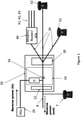
- FIG. 1 illustrates a Fibre-to-the-Distribution Point (FttDP) system when operated under an 'isolation' model.
- FttDP Fibre-to-the-Distribution Point
- a twisted copper pair 8 enters a user's premises from a remote (not shown) access node which may be a drop point unit, and is connected to a master socket 10.
- the master socket 10 includes a back plate 12 and a front plate 18.
- an interstitial plate 14 is also fitted at the master-socket 10 (an NTE5 master socket from British Telecommunications pic in this example) which effectively isolates the network cabling (i.e.
- the reverse powering system (in particular the reverse Power Supply Unit (PSU) 20) provides d.c. power along the A&B twisted copper pair to an Access Network Unit (ANU) (also referred to as a Drop Point Unit (DPU) or an Access Node (AN)) which, although not illustrated in Figure 1 , is illustrated in Figures 2-5 .
- ANU Access Network Unit
- DPU Drop Point Unit
- AN Access Node
- the modem/router/ATA 40 can include a built-in filter to separate DSL signals from POTS signals as necessary) primarily so as to prevent noise from the telephony devices 51,52 from interfering with the DSL modem of the modem/router/ATA 40 in the normal manner.
- the Modem/Router/ATA 40 provides various ports to supply broadband to the end user illustrated by the lines 41, 42, 43: these could include, for example various Ethernet connection ports, a Wi-Fi access point, etc.
- the interstitial plate also includes a differential mode balanced choke 15 for filtering out any high frequency noise coming from the PSU by isolating the PSU and any associated wiring from the twisted copper pair at frequencies above a predetermined frequency dependent upon the choke 15, preferably such as to substantially block all signals at frequencies in excess of at least a few hundred Hz, and certainly in excess of a few kilohertz (where the DSL signals start) so as to prevent any noise interfering with DSL signals or similar high frequency DMT broadband signals being carried over the twisted copper pair 8.
- a differential mode balanced choke 15 for filtering out any high frequency noise coming from the PSU by isolating the PSU and any associated wiring from the twisted copper pair at frequencies above a predetermined frequency dependent upon the choke 15, preferably such as to substantially block all signals at frequencies in excess of at least a few hundred Hz, and certainly in excess of a few kilohertz (where the DSL signals start) so as to prevent any noise interfering with DSL signals or similar high frequency DMT broadband signals being carried
- FIG. 1 Also shown in Figure 1 is a telephone 7 connected to the 'wrong' (network) side of the master-socket 10.
- a telephone could have been accidentally mis-wired and/or deliberately wired in this fashion for convenience.
- POTS/broadband operating conditions this is of little consequence - although there would be no bell signal for this telephone this is of little consequence with most modern telephones.
- FttDP Drop Point
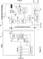
- Figure 2 shows a similar arrangement to that of Figure 1 described above, but in reference-model format, and wherein the need for even conventional POTS type splitters has been removed by isolating the entirety of the user premises wiring from any broadband signal carrying wiring.
- This can be achieved by providing a direct connection from the DSL modem to an interstitial plate within the user's master socket, where the extension wiring (including the user accessible port of the front plate of the master socket) is not connected to the backplate of the master socket (and thus to the twisted copper pair of the access network) (except via the ATA/modem device which converts between analogue telephony signals at POTS frequencies and VOIP signals carried as digital information within the broadband signal transmitted between the user's DSL modem and the corresponding DSL modem in the access network).
- a similar effect can be achieved by providing a suitable filter (such as a conventional ADSL splitter filter) to filter out any broadband signals from being carried through from the broadband signal carrying wiring (i.e. the DSL modems/twisted copper pair/back-plate of the master socket) to the user's extension wiring (which solely carries analogue telephony/POTS signals).
- a suitable filter such as a conventional ADSL splitter filter
- twisted copper pair 8 connects between a Customer Premises 100 and a Drop Point unit (DPU) 90.
- DPU Drop Point unit
- a power splitter arrangement 156 which is basically a capacitor and a choke arranged as in Figure 1 (see choke 15 and capacitor 16 of Figure 1 ).
- the elements could be differently housed in different housings, however an advantage of containing all of the illustrated elements 410, 420, 430, 210 and 220, as is done in the present embodiment, is that they can share the same management controller 414 which can manage all of the principal elements of the device especially the modem (the XDSL Transmission Unit - Remote (XTU-R) 412 in the present embodiment), the router 420, the ATA 430 and the Power insertion unit 210 (corresponding to the PSU 20 of the embodiment illustrated in Figure 1 ). Also shown in Figure 2 is that the device 40 includes a battery for providing a short period of continuance in the event of a sudden power loss from the user's premises (e.g.
- the solid line box 410 encompasses the modem 412 and the management controller 414 and is conventionally termed a broadband Network Termination unit (NT).
- the management controller 414 is shown as contained within the NT 410 despite managing numerous other elements as well because the majority of its functionality is associated with controlling the modem 410 as is well known in the art.
- FIG. 2 also illustrates the DPU 90 in some detail. As shown, in this embodiment, it includes a power splitter 956 which is similar to the power splitter 156 mutatis mutandis such that the low frequency (dc) power signals are blocked by a capacitor from passing through the interface U 02 between the power splitter 956 and the ONU/AN 910 whilst the high frequency broadband signals are prevented from passing through the interface U 02P between the power splitter 956 and the power extractor/combiner 921. Additionally, the DPU 90 includes an Optical Network Unit/Access Node (ONU/AN) 910, a power extractor/combiner unit 921, a battery 922 and a Power Supply Unit (PSU) 923.
- ONU/AN Optical Network Unit/Access Node
- PSU Power Supply Unit
- the ONU/AN 910 includes a backhaul termination unit (PHY) 911 which in the present embodiment is a an Optical Network Unit 911 connecting to an optical fibre forming part of a Passive Optical Network (PON) arrangement feeding back to a Central Office or similar, etc.; the ONU/AN additionally includes a modem 912 (in the present case an XDSL Transceiver Unit - Central Office side (XTU-O)) which corresponds to the modem 412 in the customer premises; finally, the ONU/AN is additionally shown as containing a management controller unit 914 though as with the customer premises arrangement 100, this management controller actually controls other key elements within the DPU in addition to the ONU and the XTU-O.
- PHY backhaul termination unit
- XTU-O XDSL Transceiver Unit - Central Office side
- the power extraction unit extracts power from the reverse power signal generated by the power insertion unit 210 of the customer premises and uses this to power the PSU 923 which in turns provides power in a conventional manner to the other elements in the DPU which require power.
- the battery 922 provides a small amount of back up power to enable a graceful shutdown in the event that power from the twisted copper pair is cut off for some reason. Further details of such reverse powering arrangements can be found in, for example, WO2009138711 .
- Figure 3 shows an arrangement (in a similar reference model format to that of Figure 2 ) where POTS dongles are required on the in-premises network since the dc reverse powering current and POTS share the same wiring infrastructure (in addition the ATA 430' includes a similar POTS adapter with corresponding funuctionality to the POTS Dongles 450, 451.
- some suitable technique to convert conventional analogue telephony dc signals to suitable non-dc signals is required to be performed by the POTS dongles 450, 451 (and the ATA and POTS adapter 430') to enable conventional analogue POTS signals to be carried on the same wiring as the reverse power dc signal without causing problems.
- the d.c. reverse power feed power supply (or other associated componentry within the same modem/ata/router device such as a home hub type device, etc.) is designed to detect a "signature" indicative of an inappropriately connected telephony device consuming a dangerously large amount of current from the reverse power feed supply, typically by observing a rapid increase of current being demanded from the reverse power feed power supply (which is determined as being most likely the result of an illegal (i.e.
- the reverse power supply switches into a 'fail' mode where an error indicator is illuminated on the power supply and the output voltage/current instantaneously drops to zero, in the present embodiment, until suitable remedial action is taken.
- the system determines that suitable remedial action has been taken suggesting that the inappropriately connected device (e.g. an illegal or un-dongled telephone device) has been either removed or a dongle added etc.
- an illegal/un-dongled device may be already in the off-hook state when the reverse powering supply is initially energised. In this case there would not be an (almost) instantaneous increase in demand for current that occurs when a device goes off-hook. However, the quiescent current would be significantly higher than the 'normal' current expected at power-up and thus the illegal/un-dongled device can still be detected and the PSU can switch (or remain) in 'fail' mode.
- the process described above is built into a start-up protocol for the reverse powering PSU in the present embodiment.
- this current limit detection system is made possible by limiting the rate of change of current demanded by the remote ANU.
- the power extraction/combiner circuitry built into the ANU should ensure that the positive rate of change of current demand (especially at low frequencies associated with the reverse power feed supply signal) for an individual circuit cannot occur beyond a specific value. This could be implemented by adding inductance at the ANU thus ensuring that the rate of change of current demanded by the ANU cannot exceed a specified value (within a specified voltage range).
- the system of the above described embodiments deduce that a fault condition has occurred and the PSU is shut down (entering the fail mode as described above).
- the PSU in the CPE upon shutting down (entering the fail mode), the PSU in the CPE immediately starts trying to re-negotiate connection with the ANU i.e. attempting to restore power whilst still displaying the fault condition.
- the start-up protocol negotiation between the source PSU and ANU it may be possible to indicate to the management system installed in the ANU that a powering problem exists on that specific line. This information would be useful in order to remotely diagnose the powering problem that has occurred.
- two mechanisms are provided for enabling this communication, firstly a protocol is used for communicating this information as part of an OAM channel carried within the broadband signal carried between the two modems.
- the device 430 and DPU 90 employ a very simple protocol based on d.c. or low frequency signals.
- the device 430 when in fail mode can vary the periodicity with which it attempts to renegotiate the power supply. These attempts may in many cases be detectable by the PDU (even if the size of any voltage signal to the PDU is much less than output by the reverse feed power supply bacuse most of the power supply signal is absorbed by the mis-connected telephony device) and the interval between attempts can thus be monitored to detect simple pre-arranged messages. For example, noting that the re-negotiation attempts are made every 20 seconds is indicative of the device entering the fail mode because of a detected signature indicative of an illegal/undongled telephony device.
- a low frequency ac signal can be periodically sent instead.
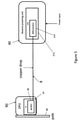
- Figure 4 illustrates in overview where the signature detection function and the current limitation functions discussed above are located in an example scenario/embodiment illustrating a customer premises (all elements 40, 210, 212, 420, 430, 450, 451 to the right of the Network Termination Equipment (NTE)/master socket 10) connected via a twisted copper pair 8 to a DPU 90 which in turn is connected by an optical fibre to a Central Office 60 containing an Optical Line Termination (OLT) unit which in turn is connected to a call server 61.
- NTE Network Termination Equipment
- the reverse powering source 210 located at the customer's premises as indicated by the NTE 10 demarcating the legal boundary between the access network owned by an access network operator and the customer's wiring
- a Current Rate Detector (CRD) 212 and in the remote unit (DPU 90 in this case) we have the Predefined Inductance (PI) 91 which provides a guaranteed minimum inductance as perceived by the reverse powering source 210 (and the CRD 212 thereof in particular).
- PI Predefined Inductance
- the combination of these two units means that it is possible to detect if an unexpected step-change in current demand occurs (phone going off-hook) and/or if the quiescent current demand of the DPU is excessively high (telephone already off-hook at reverse power system initialisation).
- FIG. 5 shows some more detail of the PI 91 and CRD 212.
- a gyrator circuit 92 provides an efficient means of setting the input inductance (LG) of the d.c. power extraction/combiner circuit of the DPU 90 (illustrated in this example as being mounted on a pole 99).
- This inductance value LG would be set to a value that limits the maximum rate of change of input current that could be achieved with the typical voltage available for reverse powering (say 0-60V d.c.).
- MELT metallic line test
- LM inductance
- a differentiator based circuit e.g. a simple operational amplifier based differentiator circuit in combination with a voltage detector
- a simple R/C low-pass filter could be used to filter the output voltage into a threshold detector in order to detect excessive current demand.
- An off-the-shelf current detection component could be used to detect the current surge but a differentiator function is required to detect a rapid rise in load current (phone going off-hook) which would be used to trigger the failure mode i.e. switch off the supply to the load and illuminate a warning LED or something similar (e.g. a sound based alarm such as a buzzer or some combination of such warning mechanisms).
- a low-pass filter acts as differentiator - i.e.
- the output from the RC filter would be zero however when there is a change in input current (which is simply measured as being proportional to the voltage across a resistor) taken then a voltage spike would be produced on the output of the filter which could then feed either into a comparator circuit where (if the spike is beyond a certain value) it would trigger some logic to switch the supply into failure mode, or the output from the filter could feed into an analogue to digital converter (usually several of these built into cheap micro-controllers) and the threshold function can be performed in the digital domain - this latter being the approach adopted in the above described embodiments.
- start-up current as seen by the source PSU is greater than this then this can be taken by the PSU as an indication that there already exists a fault condition.
- a suitable threshold amount set ideally so as to be sufficiently low that no damage will be incurred by an incorrectly connected device
- the dongles that perform the signalling conversion which should be attached to every phone on this home network.
- a phone goes off-hook on a dongled phone there would be a current surge (the same as for an un-dongled phone).
- the dongle actually adds some inductance (which again could be gyrator circuit based) so that the surge current of a dongled phone is limited much reduced when compared to an un-dongled phone.
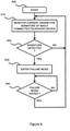
- FIG. 6 illustrates the principal steps of the method employed in embodiments of the present invention in overview.
- the overall method commences at step S05 and proceeds to a monitoring stage S10 in which the current drawn from the reverse feed power supply unit is monitored for the occurrence of a signature indicative of a misconnected device transitioning to (or initially being in) an off-hook state.
- the method determines if such a signature has indeed been detected and if so the method proceeds to step S30, but otherwise the method loops back to S10 until such a detection is made.
- the user premises device including the reverse feed power supply unit enters a fail mode in which the reverse power feed supply is switched off (or to a very low level - especially to a low level of maximum current/power draw where no damage should be caused to a misconnected device in an off-hook state) and in which a warning is generated for a user to indicate that a fail mode has been entered.
- the method then proceeds to step S40 in which it is determined whether or not the failure mode has been exited.
- the failure mode is only fully exited when a user makes a positive indication to the system that the problem (e.g. the misconnected device) has been rectified by the user (e.g.
- FIG. 7 illustrates an example PSU 20 Control unit 200 which could form part of a stand-alone control unit in alternative embodiments (note that in the embodiments illustrated in Figures 1-5 , the same functionality is instead provided within the management controller 414).
- the control unit 201 includes a processor 202 and interface 209 and a memory 204.
- the memory 204 includes a signature detection code means for identifying that a signature indicative of a misconnected telephony device being or transitioning into an off-hook state has occurred.
- a signature could include, as discussed above, wither a sharp increase in the rate of current drawn, or that the level of current drawn exceeds a predetermined absolute amount within a predetermined period of the device starting up its reverse feed power supply.
- the memory 204 also includes a failure mode operation code means 208 for causing the PSU 20 to enter a failure mode when the signature detection code means has caused the PSU to detect a predetermined signature indicative of a misconnected telephony device being or transitioning into an off-hook state. Moreover, this code means 208 also controls the PSU to then as quickly as possible (preferably within a few milliseconds) switch off its reverse feed power supply (before excess current can be drawn from the power supply sufficient to potentially cause damage to the misconnected telephony device) and to cause an alarm to be generated which is only switched off when positive input from a user has been received to confirm that suitable corrective action has been taken by the user.
- the failure mode operation code means 208 is operable to cause the PSU to regularly attempt to renegotiate a power supply signal to the PDU until it is determined that the misconnection problem has been resolved (including by the misconnected telephony device being transitioned back into an on-hook state) whereupon the reverse feed power supply is recommenced even though the PSU is not transitioned out of the failure mode (so that the alarm is not switched off until appropriate user action has occurred).
Claims (6)
- Umkehrleistungsversorgungseinheit (20, 210) zum Zuführen von elektrischer Leistung von einer Kundenanwesenvorrichtung (20, 40) zu einem Zugangsknoten (90) über ein verdrilltes Kupferpaar (8), wobei die Umkehrleistungsversorgungseinheit einen Stromzunahmeratendetektor (212) beinhaltet, der betreibbar ist zum Detektieren, ob der aus der Umgekehrte-Stromversorgung-Einheit über das verdrillte Kupferpaar (8) gezogene Strom mit einer Rate zunimmt, die eine vorbestimmte Schwelle übersteigt, die einem Signaturleistungsaufnahmemuster entspricht, das angibt, dass sich eine Telefonievorrichtung in einem abgehobenen Zustand befindet oder in einen solchen übergeht, wenn diese direkt mit der Umgekehrte-Stromversorgung-Einheit verbunden ist und nicht über eine strombegrenzende Schnittstelle verbunden ist,
und einen Strombegrenzer (208) zum Begrenzen der Menge des durch die Umgekehrte-Stromversorgung-Einheit zugeführten Stroms in dem Fall, dass der Stromzunahmeratendetektor (212) eine Stromzunahme mit einer Rate detektiert, die die vorbestimmte Schwellenmenge übersteigt. - Umkehrleistungsversorgungseinheit (20, 210) nach Anspruch 1, wobei Detektion einer Stromaufnahme-Zunahmerate über eine vorbestimmte Schwellenmenge hinaus angibt, dass sich eine Telefonievorrichtung (7) in einem abgehobenen Zustand befindet oder in einen solchen übergeht, wenn diese direkt mit der Umkehrleistungsversorgungseinheit (20, 210) verbunden ist und nicht über eine strombegrenzende Schnittstelle (16, 450, 451) verbunden ist.
- Umkehrleistungsversorgungseinheit nach Anspruch 1 oder Anspruch 2, ferner umfassend einen Stromdetektor, zusätzlich zu dem Stromzunahmeratendetektor, zum Detektieren, ob die Stromstärke eine vorbestimmte Schwellenstromstärke innerhalb eines vorbestimmten, endlichen Hochfahrzeitraums vom Beginn des Zuführens von Umkehrleistung durch die Umkehrleistungsversorgung übersteigt, wobei der Strombegrenzer (208) zusätzlich betreibbar ist zum Begrenzen der Strommenge, die durch die Umkehrleistungsversorgungseinheit (20, 201) innerhalb des vorbestimmten, endlichen Hochfahrzeitraums zugeführt wird, und nicht über eine strombegrenzende Schnittstelle (16, 450, 451) verbunden ist.
- Kundenanwesenausrüstung (100), umfassend eine Umkehrleistungsversorgungseinheit (210) gemäß einem vorhergehenden Anspruch und ferner umfassend eine oder mehrere strombegrenzende Schnittstellen (450, 451) zum Begrenzen der Zunahmerate von direktem Strom und/oder der Menge von direktem Strom, der durch die strombegrenzende Schnittstelle hindurchgeht.
- Kundenanwesenausrüstung (100) gemäß Anspruch 4, wobei die oder jede strombegrenzende Schnittstelle (450, 451) entweder in einen Dongle (450, 451) oder eine Vorrichtung, wie etwa eine Zwischenplatte (14) zum Einbau in einen Hauptanschluss (10) eines Kundenanwesens, integriert ist.
- Kundenanwesenausrüstung (100), beinhaltend eine Umkehrleistungsversorgungseinheit (20, 210) nach Anspruch 1, und ferner beinhaltend eine Strombegrenzungsanordnung (16, 156, 430), die mit einer Kundenanwesenverkabelung (30) verbunden ist, zum Begrenzen der Strommenge und/oder der maximalen Zunahmerate von Strom, der durch eine Telefonievorrichtung (51), die mit der Kundenanwesenverkabelung (30) verbunden ist, gezogen werden kann, so dass dieser nicht größer als eine vorbestimmte Menge oder Rate ist, wobei die Kundenanwesenverkabelung (30) mit dem verdrillten Kupferpaar (8) auf solche Weise verbunden ist, dass Sprachsignale von der Telefonievorrichtung (51) zu einem Zugangsknoten (90), mit dem das verdrillte Paar (8) verbunden ist, übertragen werden können.
Applications Claiming Priority (2)
| Application Number | Priority Date | Filing Date | Title |
|---|---|---|---|
| EP13250132 | 2013-12-31 | ||
| PCT/GB2014/000527 WO2015101764A1 (en) | 2013-12-31 | 2014-12-24 | Method and apparatus for use in supplying power over a telephone line |
Publications (2)
| Publication Number | Publication Date |
|---|---|
| EP3090532A1 EP3090532A1 (de) | 2016-11-09 |
| EP3090532B1 true EP3090532B1 (de) | 2022-02-23 |
Family
ID=50114256
Family Applications (1)
| Application Number | Title | Priority Date | Filing Date |
|---|---|---|---|
| EP14824064.1A Active EP3090532B1 (de) | 2013-12-31 | 2014-12-24 | Vorrichtung zur verwendung bei der stromversorgung über eine telefonleitung |
Country Status (4)
| Country | Link |
|---|---|
| US (1) | US10110755B2 (de) |
| EP (1) | EP3090532B1 (de) |
| CN (1) | CN106063239B (de) |
| WO (1) | WO2015101764A1 (de) |
Families Citing this family (17)
| Publication number | Priority date | Publication date | Assignee | Title |
|---|---|---|---|---|
| EP2830302A1 (de) * | 2013-07-23 | 2015-01-28 | British Telecommunications public limited company | Rückleistungssystem für Telekommunikationsknoten |
| US10110755B2 (en) * | 2013-12-31 | 2018-10-23 | British Telecommunications Public Limited Company | Method and apparatus for use in supplying power over a telephone line |
| WO2016026688A1 (en) | 2014-08-20 | 2016-02-25 | British Telecommunications Public Limited Company | Reverse power feed system |
| EP3286842B1 (de) * | 2015-04-20 | 2019-03-06 | Microsemi P.O.E. Ltd. | System und verfahren zur umgekehrten stromversorgung |
| EP3099005B1 (de) * | 2015-05-26 | 2019-12-25 | Alcatel Lucent | Bereitstellung neuer breitbandkommunikation durch umgekehrte stromversorgung |
| GB2539706B (en) * | 2015-06-25 | 2018-06-13 | British Telecomm | Premises telephony wiring |
| US10225009B2 (en) * | 2016-07-01 | 2019-03-05 | Adtran, Inc. | Broadband access devices having a radio link |
| WO2018008012A1 (en) | 2016-07-04 | 2018-01-11 | Microsemi P.O.E Ltd. | Reverse power feeding power sourcing equipment and method |
| CN110089052B (zh) | 2016-12-21 | 2022-02-08 | 英国电讯有限公司 | 网络节点和通信网络 |
| CN106909375A (zh) * | 2017-02-17 | 2017-06-30 | 杭州迪普科技股份有限公司 | 一种端口状态的获取方法及装置 |
| US10530497B2 (en) * | 2017-03-15 | 2020-01-07 | Methode Electronics, Inc. | Distribution point unit for high speed communications node |
| US10340977B2 (en) * | 2017-07-28 | 2019-07-02 | Microsemi P.O.E Ltd. | Reverse power feeding power sourcing equipment and method |
| US10951056B2 (en) | 2018-03-07 | 2021-03-16 | At&T Intellectual Property I, L.P. | Systems and methods for intelligent power distribution |
| CN109039659B (zh) * | 2018-06-13 | 2021-06-04 | 普联技术有限公司 | G.fast反向供电系统以及局端设备 |
| EP3859984B1 (de) * | 2020-01-30 | 2023-05-17 | Nokia Solutions and Networks Oy | Melt bei rückleistungsspeisung |
| AU2022307935A1 (en) | 2021-07-09 | 2024-02-08 | ReadyLinks Inc. | Facilitating and provisioning customer broadband transport service |
| US11750407B2 (en) * | 2021-07-09 | 2023-09-05 | ReadyLinks Inc. | Bidirectional power feed digital communication device |
Family Cites Families (43)
| Publication number | Priority date | Publication date | Assignee | Title |
|---|---|---|---|---|
| US4103112A (en) * | 1977-10-17 | 1978-07-25 | Northern Telecom Limited | Telephone line circuit with differential loop current sensing and compensation |
| US4815124A (en) | 1987-06-26 | 1989-03-21 | Tellabs, Inc. | DX circuit |
| US5473676A (en) | 1990-09-27 | 1995-12-05 | Radish Communications Systems, Inc. | Telephone handset interface for automatic switching between voice and data communications |
| US5287555A (en) * | 1991-07-22 | 1994-02-15 | Motorola, Inc. | Power control circuitry for a TDMA radio frequency transmitter |
| EP0600644A1 (de) | 1992-11-30 | 1994-06-08 | AT&T Corp. | Rufabschaltung mittels Rufspannung und Rufstrom |
| FR2720559B1 (fr) * | 1994-05-31 | 1996-07-05 | Alcatel Converters | Dispositif de synchronisation pour un système d'alimentation sécurisé. |
| CN2205615Y (zh) * | 1994-08-26 | 1995-08-16 | 陈炳煌 | 一种多用电话听筒 |
| US5848150A (en) | 1997-02-26 | 1998-12-08 | Paradyne Corporation | Passive distributed filter system and method |
| US7130338B2 (en) | 1996-12-17 | 2006-10-31 | Paradyne Corporation | Apparatus and method for communicating voice and data between a customer premises and a central office |
| US6563864B1 (en) | 1998-02-04 | 2003-05-13 | Texas Instruments Incorporated | Residential power cutback for splitterless DSL operation |
| US6269154B1 (en) | 1998-02-04 | 2001-07-31 | Texas Instruments Incorporated | Splitterless modem with integrated off-hook detector |
| US6563924B1 (en) | 1998-08-25 | 2003-05-13 | Samsung Electronics Co., Ltd. | Subscriber matching circuit for electronic exchange |
| US6724890B1 (en) | 1998-11-24 | 2004-04-20 | Premisenet Incorporated | Adaptive transmission line impedance matching device and method |
| EP1009156A2 (de) | 1998-12-10 | 2000-06-14 | Tadiran Telecommunications Limited | Verfahren und Vorrichtung zur lokale Versorgung und signaleinspeisung für Teilnehmerleitungen |
| US6522730B1 (en) | 1999-01-15 | 2003-02-18 | Texas Instruments Incorporated | DSL communication system with improved bandwidth |
| US6813343B1 (en) | 1999-05-12 | 2004-11-02 | Orckitt Communications Ltd. | Method and apparatus for filtering asymmetric digital subscriber line (ADSL) signals |
| US6690677B1 (en) | 1999-07-20 | 2004-02-10 | Serconet Ltd. | Network for telephony and data communication |
| US6671373B1 (en) * | 1999-10-20 | 2003-12-30 | Legerity, Inc. | Method and apparatus for DC feed control |
| EP1347627B1 (de) | 2002-03-20 | 2012-12-19 | Conexant Systems, Inc. | Digitale Isolationsbarriere als Busschnittstelle für Modems |
| IL154234A (en) * | 2003-01-30 | 2010-12-30 | Mosaid Technologies Inc | Method and system for providing dc power on local telephone lines |
| US7139920B2 (en) * | 2003-03-13 | 2006-11-21 | Sun Microsystems, Inc. | Method and apparatus for supplying power in electronic equipment |
| GB0322894D0 (en) | 2003-09-30 | 2003-10-29 | British Telecomm | Telephony system |
| US7580732B2 (en) | 2004-10-05 | 2009-08-25 | Spirent Communications Of Rockville, Inc. | Subscriber aggregated power |
| FR2896935A1 (fr) | 2006-06-27 | 2007-08-03 | France Telecom | Dispositif de connexion electrique d'une ligne telephonique analogique bifilaire et desserte interne associee. |
| EP1988664A1 (de) | 2007-04-30 | 2008-11-05 | British Telecommunications Public Limited Company | Kommunikationsnetzwerk |
| GB2445212B (en) | 2007-07-27 | 2008-12-03 | British Telecomm | Device for use with telecommunications equipment |
| EP2120442A1 (de) | 2008-05-15 | 2009-11-18 | BRITISH TELECOMMUNICATIONS public limited company | Leistungs-Backup-System |
| EP2120443A1 (de) | 2008-05-15 | 2009-11-18 | BRITISH TELECOMMUNICATIONS public limited company | Stromversorgungssystem |
| FR2933835B1 (fr) | 2008-07-09 | 2012-07-20 | Frederic Fouilland | Dispositif de cablage en vue d'une distribution de ligne(s) telephonique(s) voip, compatible avec differents types d'abonnement et de degroupage |
| EP2209324A1 (de) | 2009-01-15 | 2010-07-21 | BRITISH TELECOMMUNICATIONS public limited company | Verwaltung von Telekommunikationsverbindungen |
| JP4852631B2 (ja) * | 2009-06-28 | 2012-01-11 | 株式会社沖データ | 通信装置及びその接続制御方法 |
| EP2362626A1 (de) | 2010-02-15 | 2011-08-31 | British Telecommunications public limited company | Telefongerät, das einen Netzwerkknoten mit Energie versorgt |
| EP2429153A1 (de) | 2010-09-10 | 2012-03-14 | British Telecommunications Public Limited Company | System zur Bereitstellung von Daten- und Telefondiensten |
| CN101964714B (zh) * | 2010-10-28 | 2013-01-30 | 南京大学 | 唤醒远端设备的方法和系统 |
| CN101980472B (zh) * | 2010-10-28 | 2012-12-26 | 南京大学 | 带唤醒功能的远程恒压馈电方法和系统 |
| EP2456189A1 (de) | 2010-11-23 | 2012-05-23 | British Telecommunications Public Limited Company | System zur Bereitstellung von Telefon- und Datendiensten |
| US8601289B1 (en) * | 2011-02-21 | 2013-12-03 | Adtran, Inc. | Optical network unit with redundant reverse powering from customer premises equipment |
| CN103973508B (zh) * | 2013-02-01 | 2019-09-24 | 中兴通讯股份有限公司 | 一种节点设备进入及退出节能模式的方法及节点设备 |
| AU2013380826B2 (en) * | 2013-03-06 | 2016-12-08 | Huawei Technologies Co., Ltd. | Power supply circuit and power supply panel |
| EP2830302A1 (de) * | 2013-07-23 | 2015-01-28 | British Telecommunications public limited company | Rückleistungssystem für Telekommunikationsknoten |
| US10110755B2 (en) * | 2013-12-31 | 2018-10-23 | British Telecommunications Public Limited Company | Method and apparatus for use in supplying power over a telephone line |
| TWI572182B (zh) * | 2014-01-03 | 2017-02-21 | 亞旭電腦股份有限公司 | 網路架構及其局端設備與用戶端設備 |
| WO2016026688A1 (en) * | 2014-08-20 | 2016-02-25 | British Telecommunications Public Limited Company | Reverse power feed system |
-
2014
- 2014-12-24 US US15/109,366 patent/US10110755B2/en active Active
- 2014-12-24 WO PCT/GB2014/000527 patent/WO2015101764A1/en active Application Filing
- 2014-12-24 EP EP14824064.1A patent/EP3090532B1/de active Active
- 2014-12-24 CN CN201480076627.3A patent/CN106063239B/zh active Active
Also Published As
| Publication number | Publication date |
|---|---|
| US20160330334A1 (en) | 2016-11-10 |
| CN106063239B (zh) | 2021-02-09 |
| CN106063239A (zh) | 2016-10-26 |
| EP3090532A1 (de) | 2016-11-09 |
| WO2015101764A1 (en) | 2015-07-09 |
| US10110755B2 (en) | 2018-10-23 |
Similar Documents
| Publication | Publication Date | Title |
|---|---|---|
| EP3090532B1 (de) | Vorrichtung zur verwendung bei der stromversorgung über eine telefonleitung | |
| US9621712B2 (en) | Method for dealing with anomalous conditions in a reverse power network, and power injector for use in such a method | |
| US8818192B1 (en) | Optical network unit with redundant reverse powering from customer premises equipment with alarm fault discrimination indicative for power fault condition | |
| US20040268160A1 (en) | Power adapter and broadband line extender system and method | |
| US9001974B2 (en) | System for providing telephony and data services | |
| CN103339580B (zh) | 具有智能电力控制系统的数字机架接口插槽(drip)和方法 | |
| CA3029294C (en) | Reverse power feeding power sourcing equipment and method | |
| EP3117596B1 (de) | Systeme und verfahren zur bereitstellung von rückenergie an eine diensteinheit | |
| US8259929B2 (en) | Methods and apparatuses to provide a back up power supply for a network interface device | |
| US20010038635A1 (en) | Local area network (LAN) packet switch remote power system | |
| Mendelson | All you need to know about Power over Ethernet (PoE) and the IEEE 802.3 af Standard | |
| EP3143758B1 (de) | Vorrichtung und verfahren zur erkennung eines besetzten telefons in einer umgekehrten stromversorgungsarchitektur | |
| CN107534561A (zh) | 用于操作分布点单元的方法、相应的分布点单元和cpe设备 | |
| WO2013140109A1 (en) | Control of line power | |
| JP4365408B2 (ja) | 回線電力供給型(linePowered)ネットワーク要素内の電流検知回路 | |
| US7031435B2 (en) | Method and apparatus for simultaneous line-interface wiring collision detection | |
| EP3544195B1 (de) | Systeme und verfahren zur automatisierten breitbandigen stromversorgung einer verteilstelleneinheit | |
| EP3859984B1 (de) | Melt bei rückleistungsspeisung | |
| AU2020100949A4 (en) | Off-hook detection in a reverse-powered environment | |
| EP2642686A1 (de) | Steuerung der Leitungsleistung | |
| CN111133740A (zh) | 故障分析设备 | |
| MX2008005696A (en) | Methods and apparatuses to provide fault monitoring for a network interface device |
Legal Events
| Date | Code | Title | Description |
|---|---|---|---|
| PUAI | Public reference made under article 153(3) epc to a published international application that has entered the european phase |
Free format text: ORIGINAL CODE: 0009012 |
|
| 17P | Request for examination filed |
Effective date: 20160729 |
|
| AK | Designated contracting states |
Kind code of ref document: A1 Designated state(s): AL AT BE BG CH CY CZ DE DK EE ES FI FR GB GR HR HU IE IS IT LI LT LU LV MC MK MT NL NO PL PT RO RS SE SI SK SM TR |
|
| AX | Request for extension of the european patent |
Extension state: BA ME |
|
| DAX | Request for extension of the european patent (deleted) | ||
| RAP1 | Party data changed (applicant data changed or rights of an application transferred) |
Owner name: BRITISH TELECOMMUNICATIONS PUBLIC LIMITED COMPANY |
|
| STAA | Information on the status of an ep patent application or granted ep patent |
Free format text: STATUS: REQUEST FOR EXAMINATION WAS MADE |
|
| R17P | Request for examination filed (corrected) |
Effective date: 20160729 |
|
| STAA | Information on the status of an ep patent application or granted ep patent |
Free format text: STATUS: EXAMINATION IS IN PROGRESS |
|
| STAA | Information on the status of an ep patent application or granted ep patent |
Free format text: STATUS: EXAMINATION IS IN PROGRESS |
|
| 17Q | First examination report despatched |
Effective date: 20190918 |
|
| GRAP | Despatch of communication of intention to grant a patent |
Free format text: ORIGINAL CODE: EPIDOSNIGR1 |
|
| STAA | Information on the status of an ep patent application or granted ep patent |
Free format text: STATUS: GRANT OF PATENT IS INTENDED |
|
| INTG | Intention to grant announced |
Effective date: 20210922 |
|
| GRAS | Grant fee paid |
Free format text: ORIGINAL CODE: EPIDOSNIGR3 |
|
| GRAA | (expected) grant |
Free format text: ORIGINAL CODE: 0009210 |
|
| STAA | Information on the status of an ep patent application or granted ep patent |
Free format text: STATUS: THE PATENT HAS BEEN GRANTED |
|
| RAP3 | Party data changed (applicant data changed or rights of an application transferred) |
Owner name: BRITISH TELECOMMUNICATIONS PUBLIC LIMITED COMPANY |
|
| AK | Designated contracting states |
Kind code of ref document: B1 Designated state(s): AL AT BE BG CH CY CZ DE DK EE ES FI FR GB GR HR HU IE IS IT LI LT LU LV MC MK MT NL NO PL PT RO RS SE SI SK SM TR |
|
| REG | Reference to a national code |
Ref country code: GB Ref legal event code: FG4D |
|
| REG | Reference to a national code |
Ref country code: CH Ref legal event code: EP |
|
| REG | Reference to a national code |
Ref country code: AT Ref legal event code: REF Ref document number: 1471360 Country of ref document: AT Kind code of ref document: T Effective date: 20220315 |
|
| REG | Reference to a national code |
Ref country code: IE Ref legal event code: FG4D |
|
| REG | Reference to a national code |
Ref country code: DE Ref legal event code: R096 Ref document number: 602014082604 Country of ref document: DE |
|
| REG | Reference to a national code |
Ref country code: LT Ref legal event code: MG9D |
|
| REG | Reference to a national code |
Ref country code: NL Ref legal event code: MP Effective date: 20220223 |
|
| REG | Reference to a national code |
Ref country code: AT Ref legal event code: MK05 Ref document number: 1471360 Country of ref document: AT Kind code of ref document: T Effective date: 20220223 |
|
| PG25 | Lapsed in a contracting state [announced via postgrant information from national office to epo] |
Ref country code: SE Free format text: LAPSE BECAUSE OF FAILURE TO SUBMIT A TRANSLATION OF THE DESCRIPTION OR TO PAY THE FEE WITHIN THE PRESCRIBED TIME-LIMIT Effective date: 20220223 Ref country code: RS Free format text: LAPSE BECAUSE OF FAILURE TO SUBMIT A TRANSLATION OF THE DESCRIPTION OR TO PAY THE FEE WITHIN THE PRESCRIBED TIME-LIMIT Effective date: 20220223 Ref country code: PT Free format text: LAPSE BECAUSE OF FAILURE TO SUBMIT A TRANSLATION OF THE DESCRIPTION OR TO PAY THE FEE WITHIN THE PRESCRIBED TIME-LIMIT Effective date: 20220623 Ref country code: NO Free format text: LAPSE BECAUSE OF FAILURE TO SUBMIT A TRANSLATION OF THE DESCRIPTION OR TO PAY THE FEE WITHIN THE PRESCRIBED TIME-LIMIT Effective date: 20220523 Ref country code: NL Free format text: LAPSE BECAUSE OF FAILURE TO SUBMIT A TRANSLATION OF THE DESCRIPTION OR TO PAY THE FEE WITHIN THE PRESCRIBED TIME-LIMIT Effective date: 20220223 Ref country code: LT Free format text: LAPSE BECAUSE OF FAILURE TO SUBMIT A TRANSLATION OF THE DESCRIPTION OR TO PAY THE FEE WITHIN THE PRESCRIBED TIME-LIMIT Effective date: 20220223 Ref country code: HR Free format text: LAPSE BECAUSE OF FAILURE TO SUBMIT A TRANSLATION OF THE DESCRIPTION OR TO PAY THE FEE WITHIN THE PRESCRIBED TIME-LIMIT Effective date: 20220223 Ref country code: ES Free format text: LAPSE BECAUSE OF FAILURE TO SUBMIT A TRANSLATION OF THE DESCRIPTION OR TO PAY THE FEE WITHIN THE PRESCRIBED TIME-LIMIT Effective date: 20220223 Ref country code: BG Free format text: LAPSE BECAUSE OF FAILURE TO SUBMIT A TRANSLATION OF THE DESCRIPTION OR TO PAY THE FEE WITHIN THE PRESCRIBED TIME-LIMIT Effective date: 20220523 |
|
| PG25 | Lapsed in a contracting state [announced via postgrant information from national office to epo] |
Ref country code: PL Free format text: LAPSE BECAUSE OF FAILURE TO SUBMIT A TRANSLATION OF THE DESCRIPTION OR TO PAY THE FEE WITHIN THE PRESCRIBED TIME-LIMIT Effective date: 20220223 Ref country code: LV Free format text: LAPSE BECAUSE OF FAILURE TO SUBMIT A TRANSLATION OF THE DESCRIPTION OR TO PAY THE FEE WITHIN THE PRESCRIBED TIME-LIMIT Effective date: 20220223 Ref country code: GR Free format text: LAPSE BECAUSE OF FAILURE TO SUBMIT A TRANSLATION OF THE DESCRIPTION OR TO PAY THE FEE WITHIN THE PRESCRIBED TIME-LIMIT Effective date: 20220524 Ref country code: FI Free format text: LAPSE BECAUSE OF FAILURE TO SUBMIT A TRANSLATION OF THE DESCRIPTION OR TO PAY THE FEE WITHIN THE PRESCRIBED TIME-LIMIT Effective date: 20220223 Ref country code: AT Free format text: LAPSE BECAUSE OF FAILURE TO SUBMIT A TRANSLATION OF THE DESCRIPTION OR TO PAY THE FEE WITHIN THE PRESCRIBED TIME-LIMIT Effective date: 20220223 |
|
| PG25 | Lapsed in a contracting state [announced via postgrant information from national office to epo] |
Ref country code: IS Free format text: LAPSE BECAUSE OF FAILURE TO SUBMIT A TRANSLATION OF THE DESCRIPTION OR TO PAY THE FEE WITHIN THE PRESCRIBED TIME-LIMIT Effective date: 20220623 |
|
| PG25 | Lapsed in a contracting state [announced via postgrant information from national office to epo] |
Ref country code: SM Free format text: LAPSE BECAUSE OF FAILURE TO SUBMIT A TRANSLATION OF THE DESCRIPTION OR TO PAY THE FEE WITHIN THE PRESCRIBED TIME-LIMIT Effective date: 20220223 Ref country code: SK Free format text: LAPSE BECAUSE OF FAILURE TO SUBMIT A TRANSLATION OF THE DESCRIPTION OR TO PAY THE FEE WITHIN THE PRESCRIBED TIME-LIMIT Effective date: 20220223 Ref country code: RO Free format text: LAPSE BECAUSE OF FAILURE TO SUBMIT A TRANSLATION OF THE DESCRIPTION OR TO PAY THE FEE WITHIN THE PRESCRIBED TIME-LIMIT Effective date: 20220223 Ref country code: EE Free format text: LAPSE BECAUSE OF FAILURE TO SUBMIT A TRANSLATION OF THE DESCRIPTION OR TO PAY THE FEE WITHIN THE PRESCRIBED TIME-LIMIT Effective date: 20220223 Ref country code: DK Free format text: LAPSE BECAUSE OF FAILURE TO SUBMIT A TRANSLATION OF THE DESCRIPTION OR TO PAY THE FEE WITHIN THE PRESCRIBED TIME-LIMIT Effective date: 20220223 Ref country code: CZ Free format text: LAPSE BECAUSE OF FAILURE TO SUBMIT A TRANSLATION OF THE DESCRIPTION OR TO PAY THE FEE WITHIN THE PRESCRIBED TIME-LIMIT Effective date: 20220223 |
|
| REG | Reference to a national code |
Ref country code: DE Ref legal event code: R097 Ref document number: 602014082604 Country of ref document: DE |
|
| PG25 | Lapsed in a contracting state [announced via postgrant information from national office to epo] |
Ref country code: AL Free format text: LAPSE BECAUSE OF FAILURE TO SUBMIT A TRANSLATION OF THE DESCRIPTION OR TO PAY THE FEE WITHIN THE PRESCRIBED TIME-LIMIT Effective date: 20220223 |
|
| PLBE | No opposition filed within time limit |
Free format text: ORIGINAL CODE: 0009261 |
|
| STAA | Information on the status of an ep patent application or granted ep patent |
Free format text: STATUS: NO OPPOSITION FILED WITHIN TIME LIMIT |
|
| 26N | No opposition filed |
Effective date: 20221124 |
|
| PG25 | Lapsed in a contracting state [announced via postgrant information from national office to epo] |
Ref country code: SI Free format text: LAPSE BECAUSE OF FAILURE TO SUBMIT A TRANSLATION OF THE DESCRIPTION OR TO PAY THE FEE WITHIN THE PRESCRIBED TIME-LIMIT Effective date: 20220223 |
|
| PG25 | Lapsed in a contracting state [announced via postgrant information from national office to epo] |
Ref country code: IT Free format text: LAPSE BECAUSE OF FAILURE TO SUBMIT A TRANSLATION OF THE DESCRIPTION OR TO PAY THE FEE WITHIN THE PRESCRIBED TIME-LIMIT Effective date: 20220223 |
|
| REG | Reference to a national code |
Ref country code: CH Ref legal event code: PL |
|
| P01 | Opt-out of the competence of the unified patent court (upc) registered |
Effective date: 20230623 |
|
| REG | Reference to a national code |
Ref country code: BE Ref legal event code: MM Effective date: 20221231 |
|
| PG25 | Lapsed in a contracting state [announced via postgrant information from national office to epo] |
Ref country code: LU Free format text: LAPSE BECAUSE OF NON-PAYMENT OF DUE FEES Effective date: 20221224 |
|
| PG25 | Lapsed in a contracting state [announced via postgrant information from national office to epo] |
Ref country code: LI Free format text: LAPSE BECAUSE OF NON-PAYMENT OF DUE FEES Effective date: 20221231 Ref country code: IE Free format text: LAPSE BECAUSE OF NON-PAYMENT OF DUE FEES Effective date: 20221224 Ref country code: CH Free format text: LAPSE BECAUSE OF NON-PAYMENT OF DUE FEES Effective date: 20221231 |
|
| PG25 | Lapsed in a contracting state [announced via postgrant information from national office to epo] |
Ref country code: BE Free format text: LAPSE BECAUSE OF NON-PAYMENT OF DUE FEES Effective date: 20221231 |
|
| PGFP | Annual fee paid to national office [announced via postgrant information from national office to epo] |
Ref country code: GB Payment date: 20231121 Year of fee payment: 10 |
|
| PGFP | Annual fee paid to national office [announced via postgrant information from national office to epo] |
Ref country code: FR Payment date: 20231122 Year of fee payment: 10 Ref country code: DE Payment date: 20231121 Year of fee payment: 10 |
|
| PG25 | Lapsed in a contracting state [announced via postgrant information from national office to epo] |
Ref country code: HU Free format text: LAPSE BECAUSE OF FAILURE TO SUBMIT A TRANSLATION OF THE DESCRIPTION OR TO PAY THE FEE WITHIN THE PRESCRIBED TIME-LIMIT; INVALID AB INITIO Effective date: 20141224 |
|
| PG25 | Lapsed in a contracting state [announced via postgrant information from national office to epo] |
Ref country code: CY Free format text: LAPSE BECAUSE OF FAILURE TO SUBMIT A TRANSLATION OF THE DESCRIPTION OR TO PAY THE FEE WITHIN THE PRESCRIBED TIME-LIMIT Effective date: 20220223 |