EP3859363A1 - Method and apparatus for diagnosing low voltage of secondary battery cell - Google Patents
Method and apparatus for diagnosing low voltage of secondary battery cell Download PDFInfo
- Publication number
- EP3859363A1 EP3859363A1 EP19869594.2A EP19869594A EP3859363A1 EP 3859363 A1 EP3859363 A1 EP 3859363A1 EP 19869594 A EP19869594 A EP 19869594A EP 3859363 A1 EP3859363 A1 EP 3859363A1
- Authority
- EP
- European Patent Office
- Prior art keywords
- battery cell
- voltage
- charging
- preset
- parameter
- Prior art date
- Legal status (The legal status is an assumption and is not a legal conclusion. Google has not performed a legal analysis and makes no representation as to the accuracy of the status listed.)
- Granted
Links
Images







Classifications
-
- G—PHYSICS
- G01—MEASURING; TESTING
- G01R—MEASURING ELECTRIC VARIABLES; MEASURING MAGNETIC VARIABLES
- G01R31/00—Arrangements for testing electric properties; Arrangements for locating electric faults; Arrangements for electrical testing characterised by what is being tested not provided for elsewhere
- G01R31/36—Arrangements for testing, measuring or monitoring the electrical condition of accumulators or electric batteries, e.g. capacity or state of charge [SoC]
- G01R31/382—Arrangements for monitoring battery or accumulator variables, e.g. SoC
- G01R31/3842—Arrangements for monitoring battery or accumulator variables, e.g. SoC combining voltage and current measurements
-
- G—PHYSICS
- G01—MEASURING; TESTING
- G01R—MEASURING ELECTRIC VARIABLES; MEASURING MAGNETIC VARIABLES
- G01R31/00—Arrangements for testing electric properties; Arrangements for locating electric faults; Arrangements for electrical testing characterised by what is being tested not provided for elsewhere
- G01R31/36—Arrangements for testing, measuring or monitoring the electrical condition of accumulators or electric batteries, e.g. capacity or state of charge [SoC]
- G01R31/385—Arrangements for measuring battery or accumulator variables
- G01R31/3865—Arrangements for measuring battery or accumulator variables related to manufacture, e.g. testing after manufacture
-
- G—PHYSICS
- G01—MEASURING; TESTING
- G01R—MEASURING ELECTRIC VARIABLES; MEASURING MAGNETIC VARIABLES
- G01R31/00—Arrangements for testing electric properties; Arrangements for locating electric faults; Arrangements for electrical testing characterised by what is being tested not provided for elsewhere
- G01R31/36—Arrangements for testing, measuring or monitoring the electrical condition of accumulators or electric batteries, e.g. capacity or state of charge [SoC]
- G01R31/385—Arrangements for measuring battery or accumulator variables
- G01R31/387—Determining ampere-hour charge capacity or SoC
- G01R31/388—Determining ampere-hour charge capacity or SoC involving voltage measurements
-
- H—ELECTRICITY
- H01—ELECTRIC ELEMENTS
- H01M—PROCESSES OR MEANS, e.g. BATTERIES, FOR THE DIRECT CONVERSION OF CHEMICAL ENERGY INTO ELECTRICAL ENERGY
- H01M10/00—Secondary cells; Manufacture thereof
- H01M10/42—Methods or arrangements for servicing or maintenance of secondary cells or secondary half-cells
- H01M10/4285—Testing apparatus
-
- H—ELECTRICITY
- H01—ELECTRIC ELEMENTS
- H01M—PROCESSES OR MEANS, e.g. BATTERIES, FOR THE DIRECT CONVERSION OF CHEMICAL ENERGY INTO ELECTRICAL ENERGY
- H01M10/00—Secondary cells; Manufacture thereof
- H01M10/42—Methods or arrangements for servicing or maintenance of secondary cells or secondary half-cells
- H01M10/44—Methods for charging or discharging
-
- H—ELECTRICITY
- H01—ELECTRIC ELEMENTS
- H01M—PROCESSES OR MEANS, e.g. BATTERIES, FOR THE DIRECT CONVERSION OF CHEMICAL ENERGY INTO ELECTRICAL ENERGY
- H01M10/00—Secondary cells; Manufacture thereof
- H01M10/42—Methods or arrangements for servicing or maintenance of secondary cells or secondary half-cells
- H01M10/44—Methods for charging or discharging
- H01M10/446—Initial charging measures
-
- H—ELECTRICITY
- H01—ELECTRIC ELEMENTS
- H01M—PROCESSES OR MEANS, e.g. BATTERIES, FOR THE DIRECT CONVERSION OF CHEMICAL ENERGY INTO ELECTRICAL ENERGY
- H01M10/00—Secondary cells; Manufacture thereof
- H01M10/42—Methods or arrangements for servicing or maintenance of secondary cells or secondary half-cells
- H01M10/48—Accumulators combined with arrangements for measuring, testing or indicating the condition of cells, e.g. the level or density of the electrolyte
-
- H—ELECTRICITY
- H01—ELECTRIC ELEMENTS
- H01M—PROCESSES OR MEANS, e.g. BATTERIES, FOR THE DIRECT CONVERSION OF CHEMICAL ENERGY INTO ELECTRICAL ENERGY
- H01M4/00—Electrodes
- H01M4/02—Electrodes composed of, or comprising, active material
- H01M4/04—Processes of manufacture in general
- H01M4/0438—Processes of manufacture in general by electrochemical processing
- H01M4/044—Activating, forming or electrochemical attack of the supporting material
- H01M4/0445—Forming after manufacture of the electrode, e.g. first charge, cycling
- H01M4/0447—Forming after manufacture of the electrode, e.g. first charge, cycling of complete cells or cells stacks
-
- H—ELECTRICITY
- H02—GENERATION; CONVERSION OR DISTRIBUTION OF ELECTRIC POWER
- H02J—ELECTRIC POWER NETWORKS; CIRCUIT ARRANGEMENTS OR SYSTEMS FOR SUPPLYING OR DISTRIBUTING ELECTRIC POWER; SYSTEMS FOR STORING ELECTRIC ENERGY
- H02J7/00—Circuit arrangements for charging or discharging batteries or for supplying loads from batteries
- H02J7/80—Circuit arrangements for charging or discharging batteries or for supplying loads from batteries including monitoring or indicating arrangements
-
- G—PHYSICS
- G01—MEASURING; TESTING
- G01R—MEASURING ELECTRIC VARIABLES; MEASURING MAGNETIC VARIABLES
- G01R31/00—Arrangements for testing electric properties; Arrangements for locating electric faults; Arrangements for electrical testing characterised by what is being tested not provided for elsewhere
- G01R31/36—Arrangements for testing, measuring or monitoring the electrical condition of accumulators or electric batteries, e.g. capacity or state of charge [SoC]
- G01R31/382—Arrangements for monitoring battery or accumulator variables, e.g. SoC
- G01R31/3828—Arrangements for monitoring battery or accumulator variables, e.g. SoC using current integration
-
- H—ELECTRICITY
- H01—ELECTRIC ELEMENTS
- H01M—PROCESSES OR MEANS, e.g. BATTERIES, FOR THE DIRECT CONVERSION OF CHEMICAL ENERGY INTO ELECTRICAL ENERGY
- H01M10/00—Secondary cells; Manufacture thereof
- H01M10/42—Methods or arrangements for servicing or maintenance of secondary cells or secondary half-cells
- H01M10/425—Structural combination with electronic components, e.g. electronic circuits integrated to the outside of the casing
-
- Y—GENERAL TAGGING OF NEW TECHNOLOGICAL DEVELOPMENTS; GENERAL TAGGING OF CROSS-SECTIONAL TECHNOLOGIES SPANNING OVER SEVERAL SECTIONS OF THE IPC; TECHNICAL SUBJECTS COVERED BY FORMER USPC CROSS-REFERENCE ART COLLECTIONS [XRACs] AND DIGESTS
- Y02—TECHNOLOGIES OR APPLICATIONS FOR MITIGATION OR ADAPTATION AGAINST CLIMATE CHANGE
- Y02E—REDUCTION OF GREENHOUSE GAS [GHG] EMISSIONS, RELATED TO ENERGY GENERATION, TRANSMISSION OR DISTRIBUTION
- Y02E60/00—Enabling technologies; Technologies with a potential or indirect contribution to GHG emissions mitigation
- Y02E60/10—Energy storage using batteries
Definitions
- the present invention relates to a method and an apparatus for diagnosing low voltage of a secondary battery cell.
- low voltage failure was diagnosed by measuring a voltage drop according to change over time during a predetermined period (approximately 7 days to 50 days) after shipment charging, which is the last step of an activation process for the secondary batteries.
- the low voltage failure refers to a phenomenon in which a battery exhibits a voltage drop behavior above a preset self-discharge rate.
- the shipment charging for secondary batteries is 20% to 50% of SOC (state of charge).
- SOC state of charge
- a battery cell becomes in a state of being placed in a region in which a voltage change rate for the SOC is not large, so that even when micro-current leakage is generated inside the battery cell, it is difficult to identify the same.
- An aspect of the present invention provides a method and an apparatus for diagnosing low voltage of a secondary battery cell, which are capable of early diagnosis of low voltage failure of a battery cell by using properties of a region in which a voltage change rate to an SOC of the battery cell is large during a pre-aging process of an activation process for a secondary battery.
- a method and an apparatus for diagnosing low voltage of a secondary battery cell including pre-aging a battery cell, charging the battery cell according to a preset charging condition, measuring a parameter for determining low voltage failure of the battery cell, comparing the measured parameter with a reference parameter, and performing formation when the battery cell is determined to be normal.
- the parameter may be a charging time from when the charging is started to when the battery cell reaches a preset voltage.
- the charging time is either a charging time in a constant current mode or charging time in a constant current charging interval of a constant current-constant voltage mode.
- the parameter may be a cumulative current amount accumulated from when the charging is started to when the battery cell reaches a preset voltage.
- the cumulative current amount is a cumulative current amount in a constant current mode.
- the parameter may be a cumulative current amount accumulated from when the charging is started to when the battery cell reaches a preset voltage and a preset current.
- the cumulative current amount may be either a cumulative current amount in a constant current-constant voltage mode or a cumulative current amount in a constant current charging interval of the constant current-constant voltage mode.
- the parameter may be an amount of voltage drop of the battery cell from when the battery cell has reached a preset voltage and self-discharge is then started to a preset time.
- the preset voltage is set to a voltage of which a voltage change rate with respect to an SOC is greater than or equal to a preset reference value.
- the reference parameter is set differently depending on the type of the battery cell.
- an apparatus for diagnosing low voltage of a secondary battery cell including a charging unit configured to charge a battery cell according to a preset charging condition after a pre-aging process and before performing a formation process, a measurement unit configured to measure a parameter for determining low voltage failure of the battery cell, and a control unit configured to compare the measured parameter with a reference parameter and determine the low voltage failure of the battery cell on the basis of a comparison result.
- the measurement unit may measure, as the parameter, a charging time which is from when the charging is started to the battery cell reaches a preset voltage.
- the charging time is either a charging time in a constant current mode or a charging time in a constant current charging interval of a constant current-constant voltage mode.
- the measurement unit may measure, as the parameter, a cumulative current amount accumulated from when the charging is started to the battery cell reaches a preset.
- the cumulative current amount is a cumulative current amount in a constant current mode.
- the measurement unit may measure, as the parameter, a cumulative current amount accumulated from when the charging is started to the battery cell reaches a preset voltage.
- the cumulative current amount may be either a cumulative current amount in a constant current-constant voltage mode or a cumulative current amount in a constant current charging interval of the constant current-constant voltage mode.
- the measurement unit may measure, as the parameter, an amount of voltage drop of the battery cell from when the battery cell has reached a preset voltage and self-discharge is then started to a preset.
- the preset voltage is set to a voltage of which a voltage change rate with respect to an SOC is greater than or equal to a preset reference value.
- low voltage failure of a battery cell may be diagnosed early by using properties of a region in which a voltage change rate to an SOC of the battery cell is large during a pre-aging process step of an activation process, so that diagnosis time, diagnosis costs, and diagnosis accuracy may be increased compared with the prior art.
- FIG. 1 is a view showing an activation process of secondary battery manufacturing to describe low voltage inspection timing
- (a) of FIG. 1 shows an activation process of secondary battery manufacturing according to the prior art
- (b) of FIG. 1 shows an activation process of secondary battery manufacturing according to the present invention.
- an activation process of secondary battery manufacturing may include a pre-aging process, a formation process, an aging process, a degassing process, and a shipment charging process.
- the pre-aging is a process for manufacturing a battery cell (that is, a bare cell) by receiving an electrode assembly in a battery container, injecting an electrolyte thereto, and sealing the battery container.
- the formation is a process for subjecting the pre-aged battery cell to initial charging under a predetermined voltage condition (for example, a voltage higher than SEI film formation of a negative electrode).
- the aging is a process for preserving the battery cell before the battery cell is stabilized in a constant state under a preset voltage condition (for example, 3.6-3.6 V) and a preset temperature condition (for example, 50°C-70°C).
- a preset voltage condition for example, 3.6-3.6 V
- a preset temperature condition for example, 50°C-70°C
- the degassing is a process for removing unnecessary gas from the aged battery cell. As an example, if a secondary battery is circular or quadrangular, the degassing process may be omitted.
- the shipment charging is a process for charging the battery cell before shipment under a preset voltage condition (for example, 20-50% of SOC), and at the time of the shipping charging, a preset properties inspection test may be performed on the corresponding battery cell (for example, cell resistance, output, charge/discharge capacity, and the like). Subsequently, as shown in (a) of FIG. 1A , a low voltage test is typically performed through an open circuit voltage (OCV) tracking after the shipment charging process.
- OCV open circuit voltage
- FIG. 2 is a graph showing the voltage properties of a secondary battery cell to an SOC
- (b) of FIG. 2 is an enlarged graph showing a section in which the SOC is 0-8% in the graph of (a) of FIG. 2 .
- a low voltage failure cell due to defects of a separator itself which insulates an anode or the cathode, or due to the weakening of insulation resistance caused by separator breakage by impacts or foreign materials insertion during assembly, leakage current is continuously generated, so that the amount of leakage current is greater than a normal cell.
- a low voltage failure cell only has more amount of leakage current than a normal cell and has a very small amount of absolute leakage current, so that it is difficult to sense the same.
- the low voltage failure refers to a phenomenon in which a battery cell exhibits a voltage drop behavior above a preset self-discharge rate.
- the SOC has a very small value in a voltage range in which the change in cell voltage according to the change in the SOC is maximized (for example, approximately 2 V to 2.5 V) when charging is performed in the pre-aging process section, so that it is relatively easy to determine the change in the SOC caused by the change in the leakage current.
- the present invention enables early diagnosis of low voltage failure of a battery cell by using properties of a region in which a voltage change rate of an SOC is large in a capacitor region between an anode and a cathode of the battery cell during a pre-aging process step of an activation process.
- the low voltage failure in the present invention may be understood as the insulation resistance failure of a battery cell.
- FIG. 3 is a block diagram showing the configuration of an apparatus for diagnosing low voltage of a secondary battery cell according to an embodiment of the present invention.
- the apparatus for diagnosing low voltage of a secondary battery cell includes a charging unit 10, a measurement unit 20, and a control unit 30.
- the charging unit 10 is a component for charging a battery cell according to a preset charging condition after a pre-aging process.
- a pre-aging process an electrode assembly is received in a battery container and an electrolyte is injected thereto, and the mixture is subjected to an electrode wetting period of a predetermined period of time.
- the wetting period may be set differently depending on the model of a battery.
- a micro-current for example, less than 1/100 C
- a preset target voltage for example, 2 V
- the micro-current is a current which is constantly applied to the target voltage.
- the micro-current may refer to a current flowing when the target voltage is maintained in a constant voltage mode section.
- the charging unit 10 may charge the battery cell in a constant current mode or in a constant current-constant voltage mode.
- the battery cell may be charged to a preset voltage with a constant current in the constant current mode, or may be charged to a preset voltage with a constant current in the constant current-constant voltage mode and then charged to a preset current with a constant voltage.
- the measurement unit 20 is a component which measures a parameter for determining low voltage failure of a battery cell.
- the measurement unit 20 may measure the parameter for determining low voltage failure during a charging period or a self-discharge period of the battery cell.
- the measurement unit 20 may measure, as the parameter for determining low voltage failure, a charging time which is from when the charging of the battery cell is started to the battery cell reaches a preset voltage.
- the charging time is either a charging time in a constant current mode or charging time in a constant current charging interval of a constant current-constant voltage mode.
- the charging time when charged only in the constant current mode, the charging time until the preset voltage is reached may be measured.
- charging time (or a charging current amount) until the preset voltage is reached in a constant current charging section may be measured.
- the preset voltage (for example, a target voltage) is set to a voltage of which a voltage change rate with respect to an SOC is greater than or equal to a preset reference value.
- the preset voltage is set to 2.5 V or less.
- the measurement unit 20 may measure a cumulative current amount as the parameter for determining low voltage failure.
- the measurement unit 20 may measure, as the parameter for determining low voltage failure, a cumulative current amount accumulated from when the charging is started to the battery cell reaches a preset voltage.
- the cumulative current amount is a cumulative current amount in a constant current mode. In other words, when charged only in the constant current mode, the measurement unit 20 measures a cumulative current amount until the preset voltage is reached.
- the measurement unit 20 may measure, as the parameter for determining low voltage failure, a cumulative current amount accumulated from when the charging is started to the battery cell reaches a preset voltage and a preset current.
- the cumulative current amount may be either a cumulative current amount in a constant current-constant voltage mode or a cumulative current amount in a constant current charging interval of the constant current-constant voltage mode.
- the measurement unit 20 may measure a cumulative current amount in a constant current mode and a cumulative current amount in a constant voltage mode, respectively and measure the both as a combined cumulative current amount, or may measure only the cumulative current amount in the constant voltage mode.
- the measurement of the cumulative current amount in the constant voltage mode when charged to the target voltage by the constant current charging in the constant current mode and then switched to the constant voltage mode, is measuring a cumulative current amount accumulated from when the constant voltage charging is started to a charging current of the battery cell reaches a preset current.
- the measurement unit 20 may measure, as the parameter for determining low voltage failure, an amount of voltage drop (that is, an amount of change in voltage) of a battery cell from when the battery cell has reached a preset voltage and self-discharge is then started to a preset time.
- an amount of voltage drop during a self-discharge period (for example, a rest period) may be measured by self-discharging for a preset period of time after charging is performed to a voltage preset in a constant current mode.
- the self-discharge period that is, the preset period of time may be set within 24 hours.
- the self-discharge period may be set to a period of time which is at least shorter than a period of time typically taken to measure an OCV at the time of shipment charging.
- the measurement of the amount of voltage drop is exemplified as charging in a constant current mode, charging in a constant current-constant voltage mode may be applied if necessary.
- the measurement unit 20 may measure two or more parameters for determining low voltage failure and use the both for diagnosing low voltage failure. For example, when charged in a constant current-constant voltage mode, charging time until a preset voltage is reached in a constant current mode and a cumulative current amount in a constant voltage mode may be measured. Alternatively, when charged only in a constant current mode, charging time until a preset voltage is reached in the constant current mode and an amount of voltage drop during a self-discharge period may be measured.
- the measurement unit 20 may measure at least one of the charging time, the cumulative current amount, and the amount of voltage drop and use the same for diagnosing low voltage failure.
- the control unit 30 is a component which compares the measured parameter with a reference parameter and determines the low voltage failure of the battery cell on the basis of a comparison result.
- the reference parameter is a reference value set for the low voltage failure determination comparison, and may be set based on, for example, each parameter (that is, , charging time, a cumulative current amount and an amount of voltage drop) measured from a battery cell having normal insulation resistance and a battery cell having weakened insulation resistance (or a battery cell having low voltage failure). Such a reference parameter may be set differently depending on the type of the battery cell.
- control unit 30 may determine whether the battery cell is a normal battery cell or a defective battery cell by determining whether a predetermined condition is satisfied by comparing the measured parameter with a reference parameter.
- the battery cell when a parameter is charging time, if measured charging time is less than 10% of reference charging time, the battery cell may be determined to be a normal battery cell, and if 10% or greater, the battery cell may be determined to be a battery cell having low voltage failure.
- the battery cell when the difference between the measured charging time and the reference charging time is less than a predetermined reference value, the battery cell may be determined to be a normal battery cell, and if the difference is greater than or equal to the predetermined reference value, the battery cell may be determined to be a battery cell having low voltage failure.
- a parameter is a cumulative current amount
- the battery cell when a parameter is a cumulative current amount, for example, if a measured cumulative current amount is less than 140% of a reference cumulative current amount, the battery cell may be determined to be a normal battery cell, and if 140% or greater, the battery cell may be determined to be a battery cell having low voltage failure.
- the battery cell if the difference between the measured cumulative current amount and the reference cumulative current amount is less than a predetermined reference value, the battery cell may be determined to be a normal battery cell, and if the difference is greater than or equal to the predetermined reference value, the battery cell may be determined to be a battery cell having low voltage failure.
- a parameter is an amount of voltage drop
- the battery cell may be determined to be a normal battery cell, and if the difference is greater than or equal to 0.3 V, the battery cell may be determined to be a battery cell having low voltage failure.
- the battery cell may be determined to be a normal battery cell, and if the difference is greater than or equal to the predetermined reference value, the battery cell may be determined to be a battery cell having low voltage failure.
- the apparatus for diagnosing low voltage of a secondary battery cell may further include a first storage unit 40 for storing measurement parameters and a second storage unit 50 for storing reference parameters.
- the first storage unit 40 and the second storage unit 50 may be configured to be one memory device.
- the second storage unit 50 may store reference parameters for each type of the battery cell.
- control unit 30 may function as a processor for controlling a manufacturing process of a secondary battery, that is, an activation process.
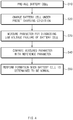
- FIG. 4 is a flow chart showing the method for diagnosing low voltage of a secondary battery cell according to an embodiment of the present invention.
- the method for diagnosing low voltage of a secondary battery cell first includes pre-aging a battery cell S10. Specifically, an electrode assembly is received in a battery container and an electrolyte is injected thereto, and the mixture is subjected to an electrode wetting period of a predetermined period of time to manufacture a battery cell.
- a battery cell is charged according to a preset charging condition S20 after the pre-aging process.
- the battery cell may be charged to a preset voltage with a constant current in a constant current mode, or may be charged to a preset voltage with a constant current in a constant current-constant voltage mode and then charged to a preset current with a constant voltage by the charging unit 10.
- the preset voltage (for example, a target voltage) is set to a voltage of which a voltage change rate with respect to an SOC is greater than or equal to a preset reference value.
- the preset voltage is set to 2.5 V or less.
- a parameter for determining low voltage failure of the battery cell is measured S30.
- the parameter for determining low voltage failure may be measured during a charging period or a self-discharge period of the battery cell by the measurement unit 20.
- the parameter may be a charging time from when the charging of the battery cell is started to when the battery cell reaches a preset voltage.
- the parameter may be a cumulative current amount.
- the parameter may be a cumulative current amount accumulated from when the charging is started to the battery cell reaches the preset voltage.
- the cumulative current amount is a cumulative current amount in a constant current mode.
- the parameter may be a cumulative current amount accumulated from when the charging is started to the battery cell reaches a preset voltage and a preset current.
- the cumulative current amount may be either a cumulative current amount in a constant current-constant voltage mode or a cumulative current amount in a constant current charging interval of the constant current-constant voltage mode.
- the parameter may be an amount of voltage drop of the battery cell from when the battery cell has reached a preset voltage and self-discharge is then started to a preset time.
- the parameter may be two or more of charging times, a cumulative current amount and an amount of voltage drop.
- the measured parameter is compared with a reference parameter S40.
- the reference parameter is a reference value set for the low voltage failure determination comparison, and may be set based on, for example, each parameter range (that is, charging time, a cumulative current amount and an amount of voltage drop) measured from a battery cell having normal insulation resistance and a battery cell having weakened insulation resistance (or a battery cell having low voltage failure).
- the reference parameter may be set differently depending on the type of the battery cell.
- the measured parameter may be compared with the reference parameter to determine whether a predetermined condition is satisfied, thereby determining whether the battery cell is a normal battery cell or a defective battery cell.
- the comparison step S40 may be performed by the control unit 30.
- the formation performance process may be performed by, for example, the control unit 30 for controlling a manufacturing process of the secondary battery, that is, an activation process.
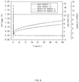
- FIG. 5 is a flow chart showing a method for diagnosing low voltage of a secondary battery cell according to an embodiment of the present invention
- FIG. 6 is a graph comparing the charging time of good and defective secondary battery cell products measured by the method according to FIG. 5 .
- the method for diagnosing low voltage of a secondary battery cell based on a charging time first includes pre-aging a battery cell S110.
- the battery cell is subjected to constant current charging S120.
- the constant current charging may be charging in a constant current mode or charging in a constant current mode of a constant current-constant voltage mode.
- the charging time starts to be measured from the start of the charging S130.
- a target voltage a preset voltage, for example, 1.5 V
- the measurement of the charging time until the target voltage is reached is terminated S150.
- the measured charging time satisfies a range of a preset reference charging time is determined S160. For example, if the measured charging time is less than 10% of the reference charging time, the battery cell is determined to be a battery cell having normal low voltage S175, and if greater than or equal to 10% of the reference charging time, the battery cell is determined to be a battery cell having low voltage failure S180.
- the range of the reference charging time is, for example, a value which is set in advance based on charging time data obtained from battery cells having insulation resistance satisfying a normal condition.
- the range of the reference charging time may be set based on each charging time ranges measured from battery cells having normal insulation resistance and battery cells having low voltage failure, further taking into account charging time data obtained from the battery cells having low voltage failure.
- the range of the reference charging time may be set differently depending on the type of the battery cell.
- FIG. 6 is a result obtained by applying a micro-current at 1/200 C in a constant current mode and cutting off at 5uA in a constant voltage mode when charging in a constant current-constant voltage mode.
- the good products of a secondary battery cell uses a jelly roll having normal insulation resistance
- the defective products of a secondary battery cell uses a jelly roll having a Hi-Pot test defect.
- the method for diagnosing low voltage of a secondary battery cell by using the charging time in the pre-aging step of the activation process of a secondary battery, it is possible to quickly and accurately determine the low voltage failure of a secondary battery earlier than a low voltage test in a typical OCV tracking process.
- FIG. 7 is a flow chart showing a method for diagnosing low voltage of a secondary battery cell according to another embodiment of the present invention
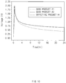
- FIG. 8 is a graph comparing the charging time between good products and defective products of a secondary battery cell measured by the method according to FIG. 7 .
- the method for diagnosing low voltage of a secondary battery cell based on a cumulative current amount first includes pre-aging a battery cell S210. Next, the battery cell is subjected to constant current charging S220. At this time, a cumulative current amount of the battery cell starts to be measured from the start of the constant current charging S225. Next, when the battery cell reaches a target voltage, the battery cell is subjected to constant voltage charging S230. For reference, in the case of a constant current-constant voltage mode, after the target voltage is reached in a constant current mode., the intensity of an applied current is decreased (for example, changed) in a constant voltage mode.
- Step S240 whether or not a charging current of the battery cell in the constant voltage mode has reached a preset target applied current is determined S240. If the charging current has not reached the target applied current (No), the determination of Step S240 is repeated. If the charging current has reached the target applied current (Yes), the measurement of the cumulative current amount until the target applied current is reached is terminated S250. Next, whether or not the measured cumulative current amount satisfies a range of a preset cumulative current amount is determined S260. For example, if the measured cumulative current amount is less than 140% of the reference cumulative current amount, the battery cell is determined to be a battery cell having normal low voltage S275, and if greater than or equal to 10% of the reference charging time, the battery cell is determined to be a battery cell having low voltage failure S285.
- the range of the reference cumulative current amount is, for example, a value which is set in advance based on cumulative current amount data obtained from battery cells having insulation resistance satisfying a normal condition.
- the range of the reference cumulative current amount may be set based on each cumulative current amount ranges measured from battery cells having normal insulation resistance and battery cells having low voltage failure, further taking into account charging time data obtained from the battery cells having low voltage failure.
- the range of the reference cumulative current amount may be set differently depending on the type of the battery cell.
- the cumulative current amount in FIG. 7 exemplifies a combined cumulative current amount of a cumulative current amount in a constant current mode and a cumulative current amount in a constant voltage mode
- the cumulative current amount may be a cumulative current amount in the constant voltage mode.
- Step S225 in which a cumulative current amount of the battery cell starts to be measured is located between Step S230 and Step S240, so that the cumulative current amount of the battery cell from the start of a constant voltage charging starts to be measured after the target voltage is reached.
- the cumulative current amount may be a cumulative current amount during a constant current charging period when charged only in a constant current mode.
- FIG. 8 is a result obtained by applying a micro-current at 1/200 C in a constant current mode and cutting off at 5uA in a constant voltage mode when charging in a constant current-constant voltage mode.
- the good products of a secondary battery cell uses a jelly roll having normal insulation resistance
- the defective products of a secondary battery cell uses a jelly roll having a Hi-Pot test defect.
- the method for diagnosing low voltage of a secondary battery cell by using the cumulative current amount in the pre-aging step of the activation process of a secondary battery, it is possible to quickly and accurately determine the low voltage failure of a secondary battery earlier than a low voltage test in a typical OCV tracking process.
- FIG. 9 is a flow chart showing a method for diagnosing low voltage of a secondary battery cell according to yet another embodiment of the present invention.
- FIG. 10 is a graph comparing the amount of voltage drop measured by the method according to FIG. 9 after charging good products and defective products of a secondary battery cell.
- the method for diagnosing low voltage of a secondary battery cell based on an amount of voltage drop first includes pre-aging a battery cell S310. Next, the battery cell is subjected to constant current charging S320. At this time, the charging is performed by applying a micro-current at 1/200 C in a constant current mode. Next, whether or not a charging voltage has reached a target voltage (for example, 2.0 V) is determined S340. If the charging voltage has not reached the target voltage (No), the determination of Step S340 is repeated. If the charging voltage has reached the target voltage (Yes), the self-discharge of the battery cell starts S350.
- a target voltage for example, 2.0 V
- a self-discharge period of time has reached a preset period of time (for example, 24 hr) is determined S355. If the self-discharge period of time has not reached the preset period of time (No), the self-discharge is repeated. If the self-discharge period of time has reached the preset period of time (Yes), the voltage of the battery cell is measured S358. Next, whether or not an amount of voltage drop for a target voltage of the measured voltage satisfies a reference amount of voltage drop is determined S360.
- a preset period of time for example, 24 hr
- the battery cell is determined to be a battery cell having normal low voltage S375, and if the difference is 0.3 V or greater, the battery cell is determined to be a battery cell having low voltage failure.
- the range of the reference amount of voltage drop is, for example, a value which is set in advance based on amount of voltage drop data obtained from battery cells having insulation resistance satisfying a normal condition.
- the range of the reference amount of voltage drop may be set based on each amount of voltage drop range measured from battery cells having normal insulation resistance and battery cells having low voltage failure, further taking into account amount of voltage drop data obtained from the battery cells having low voltage failure.
- the range of the reference amount of voltage drop may be set differently depending on the type of the battery cell.
- low voltage failure may be screened in 0.00xV, that is, a voltage fluctuation unit with a third decimal point.
- low voltage failure may be screened within 24 hours in O.xV, that is, a voltage variation unit with a first decimal point, so that the accuracy of determination may be improved.
- low voltage failure of a battery cell may be diagnosed early by using properties of a region in which a voltage change rate to an SOC of the battery cell is large during a pre-aging process step of an activation process.
- diagnosis time may be minimized. Furthermore, since early diagnosis is possible, a subsequent process for a battery cell having low voltage failure may be omitted and corresponding diagnosis time may be shortened, and, thus, diagnosis costs may be reduced to a minimum. In addition, by using properties of a region in which a voltage change rate to an SOC of the battery cell is large during a pre-aging process step, diagnosis accuracy may be increased.
Landscapes
- Engineering & Computer Science (AREA)
- Manufacturing & Machinery (AREA)
- Chemical & Material Sciences (AREA)
- Chemical Kinetics & Catalysis (AREA)
- Electrochemistry (AREA)
- General Chemical & Material Sciences (AREA)
- Physics & Mathematics (AREA)
- General Physics & Mathematics (AREA)
- Power Engineering (AREA)
- Secondary Cells (AREA)
- Charge And Discharge Circuits For Batteries Or The Like (AREA)
Abstract
Description
- This application claims the benefit of Korean Patent Application No.
10-2018-0118866, filed on October 5, 2018 - The present invention relates to a method and an apparatus for diagnosing low voltage of a secondary battery cell.
- Typically, in order to prevent the shipment of low voltage cells in the production of secondary batteries, low voltage failure was diagnosed by measuring a voltage drop according to change over time during a predetermined period (approximately 7 days to 50 days) after shipment charging, which is the last step of an activation process for the secondary batteries. Here, the low voltage failure refers to a phenomenon in which a battery exhibits a voltage drop behavior above a preset self-discharge rate.
- In general, the shipment charging for secondary batteries is 20% to 50% of SOC (state of charge). In this case, a battery cell becomes in a state of being placed in a region in which a voltage change rate for the SOC is not large, so that even when micro-current leakage is generated inside the battery cell, it is difficult to identify the same.
- As a result, there are problems in that a period of low voltage failure diagnosis (determining) is lengthened while diagnostic costs are increased, and also diagnosis accuracy is low.
- An aspect of the present invention provides a method and an apparatus for diagnosing low voltage of a secondary battery cell, which are capable of early diagnosis of low voltage failure of a battery cell by using properties of a region in which a voltage change rate to an SOC of the battery cell is large during a pre-aging process of an activation process for a secondary battery.
- According to an aspect of the present invention, there is provided a method and an apparatus for diagnosing low voltage of a secondary battery cell including pre-aging a battery cell, charging the battery cell according to a preset charging condition, measuring a parameter for determining low voltage failure of the battery cell, comparing the measured parameter with a reference parameter, and performing formation when the battery cell is determined to be normal.
- As an example, the parameter may be a charging time from when the charging is started to when the battery cell reaches a preset voltage. Here, the charging time is either a charging time in a constant current mode or charging time in a constant current charging interval of a constant current-constant voltage mode.
- Alternatively, the parameter may be a cumulative current amount accumulated from when the charging is started to when the battery cell reaches a preset voltage. Here, the cumulative current amount is a cumulative current amount in a constant current mode.
- Alternatively, the parameter may be a cumulative current amount accumulated from when the charging is started to when the battery cell reaches a preset voltage and a preset current. Here, the cumulative current amount may be either a cumulative current amount in a constant current-constant voltage mode or a cumulative current amount in a constant current charging interval of the constant current-constant voltage mode.
- Alternatively, the parameter may be an amount of voltage drop of the battery cell from when the battery cell has reached a preset voltage and self-discharge is then started to a preset time.
- Here, the preset voltage is set to a voltage of which a voltage change rate with respect to an SOC is greater than or equal to a preset reference value.
- Also, the reference parameter is set differently depending on the type of the battery cell.
- Meanwhile, according to another aspect of the present invention, there is provided an apparatus for diagnosing low voltage of a secondary battery cell, the apparatus including a charging unit configured to charge a battery cell according to a preset charging condition after a pre-aging process and before performing a formation process, a measurement unit configured to measure a parameter for determining low voltage failure of the battery cell, and a control unit configured to compare the measured parameter with a reference parameter and determine the low voltage failure of the battery cell on the basis of a comparison result.
- As an example, the measurement unit may measure, as the parameter, a charging time which is from when the charging is started to the battery cell reaches a preset voltage. Here, the charging time is either a charging time in a constant current mode or a charging time in a constant current charging interval of a constant current-constant voltage mode.
- Alternatively, the measurement unit may measure, as the parameter, a cumulative current amount accumulated from when the charging is started to the battery cell reaches a preset. Here, the cumulative current amount is a cumulative current amount in a constant current mode.
- Alternatively, the measurement unit may measure, as the parameter, a cumulative current amount accumulated from when the charging is started to the battery cell reaches a preset voltage. Here, the cumulative current amount may be either a cumulative current amount in a constant current-constant voltage mode or a cumulative current amount in a constant current charging interval of the constant current-constant voltage mode.
- Alternatively, the measurement unit may measure, as the parameter, an amount of voltage drop of the battery cell from when the battery cell has reached a preset voltage and self-discharge is then started to a preset.
- Here, the preset voltage is set to a voltage of which a voltage change rate with respect to an SOC is greater than or equal to a preset reference value.
- According to the present invention, low voltage failure of a battery cell may be diagnosed early by using properties of a region in which a voltage change rate to an SOC of the battery cell is large during a pre-aging process step of an activation process, so that diagnosis time, diagnosis costs, and diagnosis accuracy may be increased compared with the prior art.
- Other effects of the present invention will be further described in accordance with the following examples.
-
-
FIG. 1 is a view showing an activation process of secondary battery manufacturing to describe low voltage inspection timing, (a) ofFIG. 1 shows an activation process of secondary battery manufacturing according to the prior art, and (b) ofFIG. 1 shows an activation process of secondary battery manufacturing according to the present invention; - (a) of
FIG. 2 is a graph showing the voltage properties of a secondary battery cell to an SOC , and (b) ofFIG. 2 is an enlarged graph showing a section in which the SOC is 0-8% in the graph of (a) ofFIG. 2 ; -
FIG. 3 is a block diagram showing the configuration of an apparatus for diagnosing low voltage of a secondary battery cell according to an embodiment of the present invention; -
FIG. 4 is a schematic flow chart showing a method for diagnosing low voltage of a secondary battery cell according to an embodiment of the present invention; -
FIG. 5 is a flow chart showing a method for diagnosing low voltage of a secondary battery cell according to an embodiment of the present invention; -
FIG. 6 is a graph comparing the charging time of good products and defective products of a secondary battery cell measured by the method according toFIG. 5 ; -
FIG. 7 is a flow chart showing a method for diagnosing low voltage of a secondary battery cell according to another embodiment of the present invention; -
FIG. 8 is a graph comparing the cumulative current of good products and defective products of a secondary battery cell measured by the method according toFIG. 7 ; -
FIG. 9 is a flow chart showing a method for diagnosing low voltage of a secondary battery cell according to another embodiment of the present invention; and -
FIG. 10 is a graph comparing the amount of voltage drop measured by the method according toFIG. 9 after charging good products and defective products of a secondary battery cell. - Hereinafter, some embodiments of the present invention will be described in detail with reference to the accompanying drawings. In adding reference numerals to components of each drawing, it should be noted that the same reference numerals are assigned to the same components as much as possible even though they are shown in different drawings. In addition, in describing embodiments of the present invention, when it is determined that the detailed description of the related well-known configuration or function interferes with the understanding of the embodiments of the present invention, the detailed description thereof will be omitted.
- First, with reference to
FIG. 1 , an activation process of secondary battery manufacturing will be described. -
FIG. 1 is a view showing an activation process of secondary battery manufacturing to describe low voltage inspection timing, (a) ofFIG. 1 shows an activation process of secondary battery manufacturing according to the prior art, and (b) ofFIG. 1 shows an activation process of secondary battery manufacturing according to the present invention. - As shown in
FIG. 1 , an activation process of secondary battery manufacturing may include a pre-aging process, a formation process, an aging process, a degassing process, and a shipment charging process. - In general, the pre-aging is a process for manufacturing a battery cell (that is, a bare cell) by receiving an electrode assembly in a battery container, injecting an electrolyte thereto, and sealing the battery container. The formation is a process for subjecting the pre-aged battery cell to initial charging under a predetermined voltage condition (for example, a voltage higher than SEI film formation of a negative electrode). The aging is a process for preserving the battery cell before the battery cell is stabilized in a constant state under a preset voltage condition (for example, 3.6-3.6 V) and a preset temperature condition (for example, 50°C-70°C). Here, the pre-aging process, the formation process, and the aging process correspond to a wetting period. The degassing is a process for removing unnecessary gas from the aged battery cell. As an example, if a secondary battery is circular or quadrangular, the degassing process may be omitted. The shipment charging is a process for charging the battery cell before shipment under a preset voltage condition (for example, 20-50% of SOC), and at the time of the shipping charging, a preset properties inspection test may be performed on the corresponding battery cell (for example, cell resistance, output, charge/discharge capacity, and the like). Subsequently, as shown in (a) of
FIG. 1A , a low voltage test is typically performed through an open circuit voltage (OCV) tracking after the shipment charging process. - However, in the present invention, as shown in (b) of
FIG. 1 , a low voltage diagnosis is performed early between the pre-aging process and the formation process. However, the OCV tracking is omitted in (b) ofFIG. 1 , but may be additionally performed if necessary. - Next, with reference to (a) and (b) of
FIG. 2 , the reason why the low voltage diagnosis may be performed early between the pre-aging process and the formation process will be described. (a) ofFIG. 2 is a graph showing the voltage properties of a secondary battery cell to an SOC , and (b) ofFIG. 2 is an enlarged graph showing a section in which the SOC is 0-8% in the graph of (a) ofFIG. 2 . - In (a) and (b) of
FIG. 2 , changes in an anode, a cathode, and a cell voltage of a battery cell to an SOC of the battery cell during the charging of the battery cell in a pre-aging process of an activation process of a secondary battery are shown. Among the above, when looking at the change in cell voltage to the SOC, for example, as shown in (a) ofFIG. 2 , in a region in which the SOC is approximately 20-50%, the voltage is approximately 3.5-3.8 V, so that the voltage change rate is relatively small. However, as shown in (b) ofFIG. 2 , in a region in which the SOC is approximately 0.2% or less, the voltage is approximately 0-2.5 V, so that the voltage change rate is relatively large. That is, when the amount of charge is approximately 0.2% or less, the amount of change in cell voltage to the change in SOC is maximized. - Meanwhile, in the case of a low voltage failure cell, due to defects of a separator itself which insulates an anode or the cathode, or due to the weakening of insulation resistance caused by separator breakage by impacts or foreign materials insertion during assembly, leakage current is continuously generated, so that the amount of leakage current is greater than a normal cell. However, a low voltage failure cell only has more amount of leakage current than a normal cell and has a very small amount of absolute leakage current, so that it is difficult to sense the same. In particular, when the SOC is set to 20-50% during the shipment charging as in the prior art, even when micro-current leakage occurs inside the battery cell, the amount of leakage current is very small compared to the SOC, so that it is more difficult to determine the same. Here, as described above, the low voltage failure refers to a phenomenon in which a battery cell exhibits a voltage drop behavior above a preset self-discharge rate.
- However, in the case of a low voltage failure cell having weakened insulation resistance, as shown in (b) of
FIG. 2 , even in a voltage range in which the change in cell voltage according to the change in the SOC is maximized (for example, approximately 2 V to 2.5 V), for example, it has been found that when charging is performed with a micro-current (suppressing an IR drop), electrons to be charged to a cathode flows back to an anode through an area in which insulation is weak, thereby increasing the amount of charge and the charging time. Also, when charging in a constant current-constant voltage mode, it has been found that the amount of cumulative charge current is increased when a voltage is maintained due to leakage current in the constant voltage mode. Also, it has been found that the amount of voltage drop is increased due to the leakage current during a constant rest period after constant current charging. - This is because the SOC has a very small value in a voltage range in which the change in cell voltage according to the change in the SOC is maximized (for example, approximately 2 V to 2.5 V) when charging is performed in the pre-aging process section, so that it is relatively easy to determine the change in the SOC caused by the change in the leakage current.
- Accordingly, the present invention enables early diagnosis of low voltage failure of a battery cell by using properties of a region in which a voltage change rate of an SOC is large in a capacitor region between an anode and a cathode of the battery cell during a pre-aging process step of an activation process. In addition, the low voltage failure in the present invention may be understood as the insulation resistance failure of a battery cell.
- Now, specifically, the apparatus and method for diagnosing low voltage of a secondary battery cell according to the present invention will be described.
- First, with reference to
FIG. 3 , the apparatus for diagnosing low voltage of a secondary battery cell according to the present invention will be described. -
FIG. 3 is a block diagram showing the configuration of an apparatus for diagnosing low voltage of a secondary battery cell according to an embodiment of the present invention. - As shown in
FIG. 3 , the apparatus for diagnosing low voltage of a secondary battery cell according to the present invention includes a chargingunit 10, ameasurement unit 20, and acontrol unit 30. - The charging
unit 10 is a component for charging a battery cell according to a preset charging condition after a pre-aging process. For example, as the pre-aging process, an electrode assembly is received in a battery container and an electrolyte is injected thereto, and the mixture is subjected to an electrode wetting period of a predetermined period of time. At this time, the wetting period may be set differently depending on the model of a battery. Next, a micro-current (for example, less than 1/100 C) is applied to an electrode cell subjected to the electrode wetting period to a preset target voltage (for example, 2 V). Here, the micro-current is a current which is constantly applied to the target voltage. In addition, the micro-current may refer to a current flowing when the target voltage is maintained in a constant voltage mode section. At this time, the chargingunit 10 may charge the battery cell in a constant current mode or in a constant current-constant voltage mode. For example, the battery cell may be charged to a preset voltage with a constant current in the constant current mode, or may be charged to a preset voltage with a constant current in the constant current-constant voltage mode and then charged to a preset current with a constant voltage. - Next, the
measurement unit 20 is a component which measures a parameter for determining low voltage failure of a battery cell. Themeasurement unit 20 may measure the parameter for determining low voltage failure during a charging period or a self-discharge period of the battery cell. - For example, the
measurement unit 20 may measure, as the parameter for determining low voltage failure, a charging time which is from when the charging of the battery cell is started to the battery cell reaches a preset voltage. Here, the charging time is either a charging time in a constant current mode or charging time in a constant current charging interval of a constant current-constant voltage mode. As an example, when charged only in the constant current mode, the charging time until the preset voltage is reached may be measured. In addition, when charged in the constant current-constant voltage mode, charging time (or a charging current amount) until the preset voltage is reached in a constant current charging section may be measured. - Here, the preset voltage (for example, a target voltage) is set to a voltage of which a voltage change rate with respect to an SOC is greater than or equal to a preset reference value. For example, the preset voltage is set to 2.5 V or less.
- Alternatively, the
measurement unit 20 may measure a cumulative current amount as the parameter for determining low voltage failure. - As an example, the
measurement unit 20 may measure, as the parameter for determining low voltage failure, a cumulative current amount accumulated from when the charging is started to the battery cell reaches a preset voltage. Here, the cumulative current amount is a cumulative current amount in a constant current mode. In other words, when charged only in the constant current mode, themeasurement unit 20 measures a cumulative current amount until the preset voltage is reached. - Alternatively, the
measurement unit 20 may measure, as the parameter for determining low voltage failure, a cumulative current amount accumulated from when the charging is started to the battery cell reaches a preset voltage and a preset current. Here, the cumulative current amount may be either a cumulative current amount in a constant current-constant voltage mode or a cumulative current amount in a constant current charging interval of the constant current-constant voltage mode. In other words, when charged in the constant current-constant voltage mode, themeasurement unit 20 may measure a cumulative current amount in a constant current mode and a cumulative current amount in a constant voltage mode, respectively and measure the both as a combined cumulative current amount, or may measure only the cumulative current amount in the constant voltage mode. For example, the measurement of the cumulative current amount in the constant voltage mode, when charged to the target voltage by the constant current charging in the constant current mode and then switched to the constant voltage mode, is measuring a cumulative current amount accumulated from when the constant voltage charging is started to a charging current of the battery cell reaches a preset current. - As another example, the
measurement unit 20 may measure, as the parameter for determining low voltage failure, an amount of voltage drop (that is, an amount of change in voltage) of a battery cell from when the battery cell has reached a preset voltage and self-discharge is then started to a preset time. For example, an amount of voltage drop during a self-discharge period (for example, a rest period) may be measured by self-discharging for a preset period of time after charging is performed to a voltage preset in a constant current mode. The self-discharge period, that is, the preset period of time may be set within 24 hours. Alternatively, the self-discharge period may be set to a period of time which is at least shorter than a period of time typically taken to measure an OCV at the time of shipment charging. Here, although the measurement of the amount of voltage drop is exemplified as charging in a constant current mode, charging in a constant current-constant voltage mode may be applied if necessary. - In addition, the
measurement unit 20 may measure two or more parameters for determining low voltage failure and use the both for diagnosing low voltage failure. For example, when charged in a constant current-constant voltage mode, charging time until a preset voltage is reached in a constant current mode and a cumulative current amount in a constant voltage mode may be measured. Alternatively, when charged only in a constant current mode, charging time until a preset voltage is reached in the constant current mode and an amount of voltage drop during a self-discharge period may be measured. - In other words, the
measurement unit 20 may measure at least one of the charging time, the cumulative current amount, and the amount of voltage drop and use the same for diagnosing low voltage failure. - Next, the
control unit 30 is a component which compares the measured parameter with a reference parameter and determines the low voltage failure of the battery cell on the basis of a comparison result. Here, the reference parameter is a reference value set for the low voltage failure determination comparison, and may be set based on, for example, each parameter (that is, , charging time, a cumulative current amount and an amount of voltage drop) measured from a battery cell having normal insulation resistance and a battery cell having weakened insulation resistance (or a battery cell having low voltage failure). Such a reference parameter may be set differently depending on the type of the battery cell. - As an example, the
control unit 30 may determine whether the battery cell is a normal battery cell or a defective battery cell by determining whether a predetermined condition is satisfied by comparing the measured parameter with a reference parameter. - For example, when a parameter is charging time, if measured charging time is less than 10% of reference charging time, the battery cell may be determined to be a normal battery cell, and if 10% or greater, the battery cell may be determined to be a battery cell having low voltage failure. In other words, when the difference between the measured charging time and the reference charging time is less than a predetermined reference value, the battery cell may be determined to be a normal battery cell, and if the difference is greater than or equal to the predetermined reference value, the battery cell may be determined to be a battery cell having low voltage failure.
- Alternatively, when a parameter is a cumulative current amount, for example, if a measured cumulative current amount is less than 140% of a reference cumulative current amount, the battery cell may be determined to be a normal battery cell, and if 140% or greater, the battery cell may be determined to be a battery cell having low voltage failure. In other words, if the difference between the measured cumulative current amount and the reference cumulative current amount is less than a predetermined reference value, the battery cell may be determined to be a normal battery cell, and if the difference is greater than or equal to the predetermined reference value, the battery cell may be determined to be a battery cell having low voltage failure.
- Alternatively, when a parameter is an amount of voltage drop, for example, if the difference between a measured amount of voltage drop and a reference amount of voltage drop is less than 0.3, V, the battery cell may be determined to be a normal battery cell, and if the difference is greater than or equal to 0.3 V, the battery cell may be determined to be a battery cell having low voltage failure. In other words, if the difference between the measured amount of voltage drop and the reference amount of voltage drop is less than a predetermined reference value, the battery cell may be determined to be a normal battery cell, and if the difference is greater than or equal to the predetermined reference value, the battery cell may be determined to be a battery cell having low voltage failure.
- As an example, as shown in
FIG. 3 , the apparatus for diagnosing low voltage of a secondary battery cell according to the present invention may further include afirst storage unit 40 for storing measurement parameters and asecond storage unit 50 for storing reference parameters. Of course, thefirst storage unit 40 and thesecond storage unit 50 may be configured to be one memory device. - In addition, the
second storage unit 50 may store reference parameters for each type of the battery cell. - Meanwhile, the
control unit 30 may function as a processor for controlling a manufacturing process of a secondary battery, that is, an activation process. - Next, with reference to
FIG. 4 , a method for diagnosing low voltage of a secondary battery cell according to the present invention will be described.FIG. 4 is a flow chart showing the method for diagnosing low voltage of a secondary battery cell according to an embodiment of the present invention. - As shown in
FIG. 4 , the method for diagnosing low voltage of a secondary battery cell according to an embodiment of the present invention first includes pre-aging a battery cell S10. Specifically, an electrode assembly is received in a battery container and an electrolyte is injected thereto, and the mixture is subjected to an electrode wetting period of a predetermined period of time to manufacture a battery cell. - Next, a battery cell is charged according to a preset charging condition S20 after the pre-aging process. For example, the battery cell may be charged to a preset voltage with a constant current in a constant current mode, or may be charged to a preset voltage with a constant current in a constant current-constant voltage mode and then charged to a preset current with a constant voltage by the charging
unit 10. - Here, the preset voltage (for example, a target voltage) is set to a voltage of which a voltage change rate with respect to an SOC is greater than or equal to a preset reference value. For example, the preset voltage is set to 2.5 V or less.
- Next, a parameter for determining low voltage failure of the battery cell is measured S30. For example, the parameter for determining low voltage failure may be measured during a charging period or a self-discharge period of the battery cell by the
measurement unit 20. - Here, the parameter may be a charging time from when the charging of the battery cell is started to when the battery cell reaches a preset voltage.
- Alternatively, the parameter may be a cumulative current amount. For example, the parameter may be a cumulative current amount accumulated from when the charging is started to the battery cell reaches the preset voltage. Here, the cumulative current amount is a cumulative current amount in a constant current mode. Alternatively, the parameter may be a cumulative current amount accumulated from when the charging is started to the battery cell reaches a preset voltage and a preset current. Here, the cumulative current amount may be either a cumulative current amount in a constant current-constant voltage mode or a cumulative current amount in a constant current charging interval of the constant current-constant voltage mode.
- Alternatively, the parameter may be an amount of voltage drop of the battery cell from when the battery cell has reached a preset voltage and self-discharge is then started to a preset time.
- Alternatively, the parameter may be two or more of charging times, a cumulative current amount and an amount of voltage drop.
- Next, the measured parameter is compared with a reference parameter S40. Here, the reference parameter is a reference value set for the low voltage failure determination comparison, and may be set based on, for example, each parameter range (that is, charging time, a cumulative current amount and an amount of voltage drop) measured from a battery cell having normal insulation resistance and a battery cell having weakened insulation resistance (or a battery cell having low voltage failure). The reference parameter may be set differently depending on the type of the battery cell.
- In addition, in the comparison step S40, the measured parameter may be compared with the reference parameter to determine whether a predetermined condition is satisfied, thereby determining whether the battery cell is a normal battery cell or a defective battery cell. The comparison step S40 may be performed by the
control unit 30. - Next, formation is performed S50 when the battery cell is determined to be normal. The formation performance process may be performed by, for example, the
control unit 30 for controlling a manufacturing process of the secondary battery, that is, an activation process. - Next, with reference to
FIG. 5 andFIG. 6 , a method for diagnosing low voltage failure of a secondary battery cell based on charging time according to an embodiment of the present invention will be described.FIG. 5 is a flow chart showing a method for diagnosing low voltage of a secondary battery cell according to an embodiment of the present invention, andFIG. 6 is a graph comparing the charging time of good and defective secondary battery cell products measured by the method according toFIG. 5 . - As shown in
FIG. 5 , the method for diagnosing low voltage of a secondary battery cell based on a charging time according to an embodiment of the present invention first includes pre-aging a battery cell S110. Next, the battery cell is subjected to constant current charging S120. Here, the constant current charging may be charging in a constant current mode or charging in a constant current mode of a constant current-constant voltage mode. At this time, the charging time starts to be measured from the start of the charging S130. Next, whether or not a charging voltage has reached a target voltage (a preset voltage, for example, 1.5 V) is determined S140. If the charging voltage has not reached the target voltage (No), the determination of Step S140 is repeated. If the charging voltage has reached the target voltage (Yes), the measurement of the charging time until the target voltage is reached is terminated S150. Next, whether or not the measured charging time satisfies a range of a preset reference charging time is determined S160. For example, if the measured charging time is less than 10% of the reference charging time, the battery cell is determined to be a battery cell having normal low voltage S175, and if greater than or equal to 10% of the reference charging time, the battery cell is determined to be a battery cell having low voltage failure S180. Here, the range of the reference charging time is, for example, a value which is set in advance based on charging time data obtained from battery cells having insulation resistance satisfying a normal condition. In addition, the range of the reference charging time may be set based on each charging time ranges measured from battery cells having normal insulation resistance and battery cells having low voltage failure, further taking into account charging time data obtained from the battery cells having low voltage failure. The range of the reference charging time may be set differently depending on the type of the battery cell. - When comparing the charging time between good products and defective products of a secondary battery cell measured by the method according to
FIG. 5 , as shown inFIG. 6 , it can be seen that battery cells ofgood products # 1 and #2 reach a voltage of 1.5 V earlier than battery cells ofdefective products # 1 and #2 in a constant current section, and charging time until reaching the voltage of 1.5 V was 10% or greater for the battery cells of defective products than for the battery cells of good products. For reference,FIG. 6 is a result obtained by applying a micro-current at 1/200 C in a constant current mode and cutting off at 5uA in a constant voltage mode when charging in a constant current-constant voltage mode. The good products of a secondary battery cell uses a jelly roll having normal insulation resistance, and the defective products of a secondary battery cell uses a jelly roll having a Hi-Pot test defect. - According to the method for diagnosing low voltage of a secondary battery cell according to the present invention, by using the charging time in the pre-aging step of the activation process of a secondary battery, it is possible to quickly and accurately determine the low voltage failure of a secondary battery earlier than a low voltage test in a typical OCV tracking process.
- Next, with reference to
FIG. 7 andFIG. 8 , a method for diagnosing low voltage failure of a secondary battery cell based on a cumulative current amount according to another embodiment of the present invention will be described.FIG. 7 is a flow chart showing a method for diagnosing low voltage of a secondary battery cell according to another embodiment of the present invention, andFIG. 8 is a graph comparing the charging time between good products and defective products of a secondary battery cell measured by the method according toFIG. 7 . - As shown in
FIG. 7 , the method for diagnosing low voltage of a secondary battery cell based on a cumulative current amount according to an embodiment of the present invention first includes pre-aging a battery cell S210. Next, the battery cell is subjected to constant current charging S220. At this time, a cumulative current amount of the battery cell starts to be measured from the start of the constant current charging S225. Next, when the battery cell reaches a target voltage, the battery cell is subjected to constant voltage charging S230. For reference, in the case of a constant current-constant voltage mode, after the target voltage is reached in a constant current mode., the intensity of an applied current is decreased (for example, changed) in a constant voltage mode. Next, whether or not a charging current of the battery cell in the constant voltage mode has reached a preset target applied current is determined S240. If the charging current has not reached the target applied current (No), the determination of Step S240 is repeated. If the charging current has reached the target applied current (Yes), the measurement of the cumulative current amount until the target applied current is reached is terminated S250. Next, whether or not the measured cumulative current amount satisfies a range of a preset cumulative current amount is determined S260. For example, if the measured cumulative current amount is less than 140% of the reference cumulative current amount, the battery cell is determined to be a battery cell having normal low voltage S275, and if greater than or equal to 10% of the reference charging time, the battery cell is determined to be a battery cell having low voltage failure S285. Here, the range of the reference cumulative current amount is, for example, a value which is set in advance based on cumulative current amount data obtained from battery cells having insulation resistance satisfying a normal condition. In addition, the range of the reference cumulative current amount may be set based on each cumulative current amount ranges measured from battery cells having normal insulation resistance and battery cells having low voltage failure, further taking into account charging time data obtained from the battery cells having low voltage failure. The range of the reference cumulative current amount may be set differently depending on the type of the battery cell. - However, the cumulative current amount in
FIG. 7 exemplifies a combined cumulative current amount of a cumulative current amount in a constant current mode and a cumulative current amount in a constant voltage mode, but the cumulative current amount may be a cumulative current amount in the constant voltage mode. In this case, Step S225 in which a cumulative current amount of the battery cell starts to be measured is located between Step S230 and Step S240, so that the cumulative current amount of the battery cell from the start of a constant voltage charging starts to be measured after the target voltage is reached. In addition, as described above, the cumulative current amount may be a cumulative current amount during a constant current charging period when charged only in a constant current mode. - When comparing the cumulative current amount between good products and defective products of a secondary battery cell measured by the method according to
FIG. 7 , as shown inFIG. 8 , when a current in a constant current mode section and a current in a constant voltage mode section were accumulated, it was confirmed that the battery cells of defective products consumed about 40% more current than the battery cells of good products thereof based on 24 hours. For reference,FIG. 8 is a result obtained by applying a micro-current at 1/200 C in a constant current mode and cutting off at 5uA in a constant voltage mode when charging in a constant current-constant voltage mode. The good products of a secondary battery cell uses a jelly roll having normal insulation resistance, and the defective products of a secondary battery cell uses a jelly roll having a Hi-Pot test defect. - According to the method for diagnosing low voltage of a secondary battery cell according to the present invention, by using the cumulative current amount in the pre-aging step of the activation process of a secondary battery, it is possible to quickly and accurately determine the low voltage failure of a secondary battery earlier than a low voltage test in a typical OCV tracking process.
- Next, with reference to
FIG. 9 andFIG. 10 , a method for diagnosing low voltage failure of a secondary battery cell based on an amount of voltage drop according to yet another embodiment of the present invention will be described.FIG. 9 is a flow chart showing a method for diagnosing low voltage of a secondary battery cell according to yet another embodiment of the present invention.FIG. 10 is a graph comparing the amount of voltage drop measured by the method according toFIG. 9 after charging good products and defective products of a secondary battery cell. - As shown in
FIG. 9 , the method for diagnosing low voltage of a secondary battery cell based on an amount of voltage drop according to an embodiment of the present invention first includes pre-aging a battery cell S310. Next, the battery cell is subjected to constant current charging S320. At this time, the charging is performed by applying a micro-current at 1/200 C in a constant current mode. Next, whether or not a charging voltage has reached a target voltage (for example, 2.0 V) is determined S340. If the charging voltage has not reached the target voltage (No), the determination of Step S340 is repeated. If the charging voltage has reached the target voltage (Yes), the self-discharge of the battery cell starts S350. Next, whether or not a self-discharge period of time has reached a preset period of time (for example, 24 hr) is determined S355. If the self-discharge period of time has not reached the preset period of time (No), the self-discharge is repeated. If the self-discharge period of time has reached the preset period of time (Yes), the voltage of the battery cell is measured S358. Next, whether or not an amount of voltage drop for a target voltage of the measured voltage satisfies a reference amount of voltage drop is determined S360. For example, if the difference between the measured amount of voltage drop and the reference amount of voltage drop is less than 0.3 V, the battery cell is determined to be a battery cell having normal low voltage S375, and if the difference is 0.3 V or greater, the battery cell is determined to be a battery cell having low voltage failure. Here, the range of the reference amount of voltage drop is, for example, a value which is set in advance based on amount of voltage drop data obtained from battery cells having insulation resistance satisfying a normal condition. In addition, the range of the reference amount of voltage drop may be set based on each amount of voltage drop range measured from battery cells having normal insulation resistance and battery cells having low voltage failure, further taking into account amount of voltage drop data obtained from the battery cells having low voltage failure. The range of the reference amount of voltage drop may be set differently depending on the type of the battery cell. - When comparing the amount of voltage drop between good products and defective products of a secondary battery cell measured by the method according to
FIG. 9 , as shown inFIG. 10 , it can be seen that the amount of voltage variation between battery cells of defective products and battery cells of good products after being charged to 2.0 V followed by self-discharging for 24 hours exhibited a difference of approximately 0.3 V or greater. For reference, inFIG. 10 , the good products of a secondary battery cell uses a jelly roll having normal insulation resistance, and the defective products of a secondary battery cell uses a jelly roll having a Hi-Pot test defect. According to the above results, in the case in which self-discharge is performed for 13 days after shipment charge based on a typical low voltage diagnostic method, low voltage failure may be screened in 0.00xV, that is, a voltage fluctuation unit with a third decimal point. However, during a low voltage diagnosis according to the present invention, low voltage failure may be screened within 24 hours in O.xV, that is, a voltage variation unit with a first decimal point, so that the accuracy of determination may be improved. - According to the present invention, low voltage failure of a battery cell may be diagnosed early by using properties of a region in which a voltage change rate to an SOC of the battery cell is large during a pre-aging process step of an activation process.
- In addition, according to the present invention, it is possible to determine low voltage within approximately 24 hours when compared to a typical low voltage determination period of 7-14 days, so that diagnosis time may be minimized. Furthermore, since early diagnosis is possible, a subsequent process for a battery cell having low voltage failure may be omitted and corresponding diagnosis time may be shortened, and, thus, diagnosis costs may be reduced to a minimum. In addition, by using properties of a region in which a voltage change rate to an SOC of the battery cell is large during a pre-aging process step, diagnosis accuracy may be increased.
- Although the present invention has been described with reference to the preferred embodiments and the drawings, it is to be understood that the invention is not limited thereto, and it is to be understood by those skilled in the art that various changes in form and details may be made therein without departing from the spirit and scope of the invention as defined by the following claims.
-
- 10: charging unit
- 20: measurement unit
- 30: control unit
- 40: first storage unit
- 50: second storage unit
Claims (19)
- A method for diagnosing low voltage of a secondary battery cell, the method comprising:pre-aging a battery cell;charging the battery cell according to a preset charging condition;measuring a parameter for determining low voltage failure of the battery cell;comparing the measured parameter with a reference parameter; andperforming formation when the battery cell is determined to be normal.
- The method of claim 1, wherein the parameter is a charging time from when the charging is started to when the battery cell reaches a preset voltage.
- The method of claim 2, wherein the charging time is either a charging time in a constant current mode, or a charging time in a constant current charging interval of a constant current-constant voltage mode.
- The method of claim 1, wherein the parameter is a cumulative current amount accumulated from when the charging is started to when the battery cell reaches a preset voltage.
- The method of claim 4, wherein the cumulative current amount is a cumulative current amount in a constant current mode.
- The method of claim 1, wherein the parameter is a cumulative current amount accumulated from when the charging is started to when the battery cell reaches a preset voltage and a preset current.
- The method of claim 6, wherein the cumulative current amount is either a cumulative current amount in a constant current-constant voltage mode, or a cumulative current amount in a constant current charging interval of the constant current-constant voltage mode.
- The method of claim 1, wherein the parameter is an amount of voltage drop of the battery cell from when the battery cell has reached a preset voltage and self-discharge is then started to a preset time.
- The method of any one of claims 2 to 8, wherein the preset voltage is set to a voltage of which a voltage change rate with respect to an SOC is greater than or equal to a preset reference value.
- The method of claim 1, wherein the reference parameter is set differently depending on the type of the battery cell.
- An apparatus for diagnosing low voltage of a secondary battery cell, the apparatus comprising:a charging unit configured to charge a battery cell according to a preset charging condition after a pre-aging process and before performing a formation process;a measurement unit configured to measure a parameter for determining low voltage failure of the battery cell; anda control unit configured to compare the measured parameter with a reference parameter and determine the low voltage failure of the battery cell on the basis of a comparison result.
- The apparatus of claim 11, wherein the measurement unit measures, as the parameter, a charging time from when the charging is started to when the battery cell reaches a preset voltage.
- The apparatus of claim 12, wherein the charging time is either a charging time in a constant current mode, or a charging time in a constant current charging interval of a constant current-constant voltage mode.
- The apparatus of claim 11, wherein the measurement unit measures, as the parameter, a cumulative current amount accumulated from when the charging is started to when the battery cell reaches a preset voltage.
- The apparatus of claim 14, wherein the cumulative current amount is a cumulative current amount in a constant current mode.
- The apparatus of claim 11, wherein the measurement unit measures, as the parameter, a cumulative current amount accumulated from when the charging is started to when the battery cell reaches a preset voltage and a preset current.
- The apparatus of claim 16, wherein the cumulative current amount is either a cumulative current amount in a constant current-constant voltage mode, or a cumulative current amount in a constant current charging interval of the constant current-constant voltage mode.
- The apparatus of claim 11, wherein the measurement unit measures, as the parameter, an amount of voltage drop of the battery cell from when the battery cell has reached a preset voltage and self-discharge is then started to a preset time.
- The method of any one of claims 12 to 18, wherein the preset voltage is set to a voltage of which a voltage change rate with respect to an SOC is greater than or equal to a preset reference value.
Applications Claiming Priority (2)
| Application Number | Priority Date | Filing Date | Title |
|---|---|---|---|
| KR1020180118866A KR102391533B1 (en) | 2018-10-05 | 2018-10-05 | Method for diagnosing a low voltage of a secondary cell and apparatus thereof |
| PCT/KR2019/013027 WO2020071848A1 (en) | 2018-10-05 | 2019-10-04 | Method and apparatus for diagnosing low voltage of secondary battery cell |
Publications (3)
| Publication Number | Publication Date |
|---|---|
| EP3859363A1 true EP3859363A1 (en) | 2021-08-04 |
| EP3859363A4 EP3859363A4 (en) | 2021-12-08 |
| EP3859363B1 EP3859363B1 (en) | 2024-07-31 |
Family
ID=70054856
Family Applications (1)
| Application Number | Title | Priority Date | Filing Date |
|---|---|---|---|
| EP19869594.2A Active EP3859363B1 (en) | 2018-10-05 | 2019-10-04 | Method and apparatus for diagnosing low voltage of secondary battery cell |
Country Status (8)
| Country | Link |
|---|---|
| US (1) | US11940501B2 (en) |
| EP (1) | EP3859363B1 (en) |
| KR (1) | KR102391533B1 (en) |
| CN (1) | CN112888954B (en) |
| ES (1) | ES2985571T3 (en) |
| HU (1) | HUE067884T2 (en) |
| PL (1) | PL3859363T3 (en) |
| WO (1) | WO2020071848A1 (en) |
Cited By (2)
| Publication number | Priority date | Publication date | Assignee | Title |
|---|---|---|---|---|
| JP2023551269A (en) * | 2021-10-26 | 2023-12-07 | エルジー エナジー ソリューション リミテッド | Secondary battery low voltage failure determination system and secondary battery failure determination method using the same |
| JP2024509063A (en) * | 2022-01-25 | 2024-02-29 | エルジー エナジー ソリューション リミテッド | Low voltage defect inspection method for lithium secondary battery and method for manufacturing lithium secondary battery |
Families Citing this family (15)
| Publication number | Priority date | Publication date | Assignee | Title |
|---|---|---|---|---|
| KR102772785B1 (en) * | 2019-05-09 | 2025-02-27 | 주식회사 엘지에너지솔루션 | Manufacturing methods for the secondary battery |
| KR102773463B1 (en) * | 2020-05-22 | 2025-02-27 | 주식회사 엘지에너지솔루션 | Methods of activation for secondary battery |
| KR102779618B1 (en) * | 2020-06-10 | 2025-03-10 | 주식회사 엘지에너지솔루션 | System for self examination of end of life inspecting device and method thereof |
| KR102673263B1 (en) | 2020-09-22 | 2024-06-10 | 주식회사 엘지에너지솔루션 | Apparatus and method for calculating resistor |
| KR102707237B1 (en) | 2020-09-22 | 2024-09-20 | 주식회사 엘지에너지솔루션 | Method for detecting a low voltage defective battery cell |
| CN114966433B (en) * | 2022-06-15 | 2025-07-08 | 北京海博思创科技股份有限公司 | Positioning method, device, equipment and medium for self-discharge abnormality of battery pack |
| CN115825774B (en) * | 2022-08-08 | 2025-09-23 | 宁德时代新能源科技股份有限公司 | Battery detection method, device, equipment, storage medium and program product |
| WO2024031261A1 (en) * | 2022-08-08 | 2024-02-15 | 宁德时代新能源科技股份有限公司 | Battery testing method, apparatus, device, storage medium and program product |
| CN115784313B (en) * | 2022-11-23 | 2024-05-28 | 北京化工大学 | In-situ surface modification method of lithium-rich manganese-based layered cathode material |
| KR20240101185A (en) * | 2022-12-23 | 2024-07-02 | 주식회사 엘지에너지솔루션 | Internal short diagnosis method of battery and battery ststem providing the same |
| CN116148694A (en) * | 2022-12-28 | 2023-05-23 | 湖北亿纬动力有限公司 | A screening method, device, equipment and storage medium for lithium-ion batteries |
| KR20240112658A (en) | 2023-01-12 | 2024-07-19 | 에스케이온 주식회사 | Apparatus and method for detecting defective battery cell |
| KR102859338B1 (en) * | 2023-03-09 | 2025-09-11 | 주식회사 엘지에너지솔루션 | Device for detecting low voltage battery cell and operating method thereof |
| KR20250039729A (en) * | 2023-09-14 | 2025-03-21 | 주식회사 엘지에너지솔루션 | Apparatus for diagnosing battery and operating method thereof |
| KR20260004096A (en) * | 2024-07-01 | 2026-01-08 | 주식회사 엘지에너지솔루션 | Battery cell formation system and method |
Family Cites Families (28)
| Publication number | Priority date | Publication date | Assignee | Title |
|---|---|---|---|---|
| JP2002199608A (en) * | 2000-12-25 | 2002-07-12 | Nec Tokin Tochigi Ltd | Initial charging method of secondary battery |
| CN1204649C (en) * | 2001-07-27 | 2005-06-01 | 三菱化学株式会社 | Nonaqueous electrolyte solution and nonaqueous electrolyte solution secondary battery using the same |
| CN1876256B (en) | 2005-06-06 | 2010-05-12 | 深圳市比克电池有限公司 | Battery screening system and method |
| JP2007304006A (en) * | 2006-05-12 | 2007-11-22 | Nec Corp | Secondary battery charge/discharge inspection device and method |
| KR100970841B1 (en) * | 2008-08-08 | 2010-07-16 | 주식회사 엘지화학 | Battery capacity deterioration estimation apparatus and method using battery voltage behavior |
| KR101024318B1 (en) | 2010-03-24 | 2011-03-23 | (주) 에이프로 | Rechargeable battery formation unit |
| JP5533785B2 (en) | 2011-05-27 | 2014-06-25 | 株式会社デンソー | Charger |
| KR101526641B1 (en) * | 2011-12-08 | 2015-06-08 | 현대자동차주식회사 | Degradation estimation method for high voltage battery of vehicle |
| JP2014002009A (en) * | 2012-06-18 | 2014-01-09 | Toyota Motor Corp | Method of inspecting secondary battery |
| JP5768769B2 (en) * | 2012-06-26 | 2015-08-26 | トヨタ自動車株式会社 | Secondary battery inspection method |
| JP2014222603A (en) * | 2013-05-13 | 2014-11-27 | トヨタ自動車株式会社 | Inspection method for battery |
| KR101802002B1 (en) * | 2013-10-30 | 2017-11-27 | 주식회사 엘지화학 | System for early checking a fail rate by low voltage in a secondary battery and method thereof |
| JP6256761B2 (en) | 2014-04-11 | 2018-01-10 | トヨタ自動車株式会社 | Secondary battery inspection method and manufacturing method |
| JP2017139054A (en) | 2014-04-28 | 2017-08-10 | 株式会社日立製作所 | Lithium ion secondary battery system and degradation diagnosis method for lithium ion secondary battery |
| KR101779245B1 (en) * | 2014-06-17 | 2017-09-26 | 주식회사 엘지화학 | System for checking a fail in a secondary battery and method thereof |
| KR101769182B1 (en) * | 2014-06-24 | 2017-08-30 | 주식회사 엘지화학 | Method for detecting a secondary battery whose electrolyte is defectively impregnated |
| CN203951163U (en) | 2014-07-08 | 2014-11-19 | 国网山东夏津县供电公司 | Low voltage failure detector |
| US9746524B2 (en) * | 2014-09-12 | 2017-08-29 | Measurement Ltd. | System and method for monitoring battery status |
| JP6308145B2 (en) | 2015-02-27 | 2018-04-11 | トヨタ自動車株式会社 | Secondary battery inspection method |
| CN105929333B (en) | 2015-02-27 | 2019-08-16 | 丰田自动车株式会社 | The inspection method of secondary cell |
| KR102227302B1 (en) | 2016-07-29 | 2021-03-15 | 주식회사 엘지화학 | Positive electrode active material compositiom for secondary battery and secondary battery comprising the same |
| JP2018092790A (en) | 2016-12-02 | 2018-06-14 | トヨタ自動車株式会社 | Method for manufacturing lithium ion secondary battery |
| KR102194845B1 (en) * | 2016-12-20 | 2020-12-23 | 주식회사 엘지화학 | Apparatus and method for inspecting low voltage defect of secondary battery |
| KR102574500B1 (en) * | 2017-01-05 | 2023-09-05 | 주식회사 엘지에너지솔루션 | Method for detecting a low voltage defective secondary battery |
| KR102064459B1 (en) | 2017-01-05 | 2020-01-09 | 주식회사 엘지화학 | Method and apparatus for inspecting low voltage defect of secondary battery |
| JP6897765B2 (en) * | 2017-04-28 | 2021-07-07 | 株式会社Gsユアサ | Management device, power storage device and power storage system |
| TWI621866B (en) * | 2017-05-05 | 2018-04-21 | 致茂電子股份有限公司 | Test method for semi-finished product of battery core |
| US11435404B2 (en) * | 2020-09-28 | 2022-09-06 | Analog Devices International Unlimited Company | Battery formation/testing |
-
2018
- 2018-10-05 KR KR1020180118866A patent/KR102391533B1/en active Active
-
2019
- 2019-10-04 ES ES19869594T patent/ES2985571T3/en active Active
- 2019-10-04 EP EP19869594.2A patent/EP3859363B1/en active Active
- 2019-10-04 US US17/281,361 patent/US11940501B2/en active Active
- 2019-10-04 HU HUE19869594A patent/HUE067884T2/en unknown
- 2019-10-04 WO PCT/KR2019/013027 patent/WO2020071848A1/en not_active Ceased
- 2019-10-04 PL PL19869594.2T patent/PL3859363T3/en unknown
- 2019-10-04 CN CN201980065435.5A patent/CN112888954B/en active Active
Cited By (6)
| Publication number | Priority date | Publication date | Assignee | Title |
|---|---|---|---|---|
| JP2023551269A (en) * | 2021-10-26 | 2023-12-07 | エルジー エナジー ソリューション リミテッド | Secondary battery low voltage failure determination system and secondary battery failure determination method using the same |
| JP7517665B2 (en) | 2021-10-26 | 2024-07-17 | エルジー エナジー ソリューション リミテッド | System for determining low voltage defects of secondary batteries and method for determining defects of secondary batteries using the same |
| EP4239349A4 (en) * | 2021-10-26 | 2024-12-11 | LG Energy Solution, Ltd. | SYSTEM FOR DETERMINING DEFECTIVE LOW-VOLTAGE SECONDARY BATTERIES AND METHOD FOR DETERMINING DEFECTIVE SECONDARY BATTERIES THEREOF |
| JP2024509063A (en) * | 2022-01-25 | 2024-02-29 | エルジー エナジー ソリューション リミテッド | Low voltage defect inspection method for lithium secondary battery and method for manufacturing lithium secondary battery |
| EP4276973A4 (en) * | 2022-01-25 | 2024-08-21 | LG Energy Solution, Ltd. | METHOD FOR INSPECTING LOW VOLTAGE DEFECT IN LITHIUM SECONDARY BATTERY AND METHOD FOR MANUFACTURING LITHIUM SECONDARY BATTERY |
| EP4276973B1 (en) | 2022-01-25 | 2025-06-25 | LG Energy Solution, Ltd. | Low-voltage defect inspection method of lithium secondary battery and manufacturing method of lithium secondary battery |
Also Published As
| Publication number | Publication date |
|---|---|
| CN112888954B (en) | 2024-05-10 |
| WO2020071848A1 (en) | 2020-04-09 |
| KR102391533B1 (en) | 2022-04-28 |
| PL3859363T3 (en) | 2024-11-04 |
| KR20200039215A (en) | 2020-04-16 |
| CN112888954A (en) | 2021-06-01 |
| ES2985571T3 (en) | 2024-11-06 |
| HUE067884T2 (en) | 2024-11-28 |
| EP3859363A4 (en) | 2021-12-08 |
| US11940501B2 (en) | 2024-03-26 |
| US20220043068A1 (en) | 2022-02-10 |
| EP3859363B1 (en) | 2024-07-31 |
Similar Documents
| Publication | Publication Date | Title |
|---|---|---|
| EP3859363B1 (en) | Method and apparatus for diagnosing low voltage of secondary battery cell | |
| JP6252439B2 (en) | Abnormality detection method and abnormality detection device for secondary battery | |
| KR101779245B1 (en) | System for checking a fail in a secondary battery and method thereof | |
| US10502794B2 (en) | Method and system for predicting the time required for low voltage expression of a secondary battery, and aging method of the secondary battery using the same | |
| JP6090093B2 (en) | Secondary battery inspection method and inspection device | |
| EP4009413A1 (en) | Device for assessing degree of degradation of secondary battery, and assembled battery | |
| US10473725B2 (en) | Method and system for calculating low voltage expression level of a secondary battery | |
| CN110850306B (en) | Inspection method and manufacturing method of electrical storage device | |
| JP2014025858A (en) | Secondary battery pre-shipment inspection method | |
| CN102590623A (en) | Secondary battery tester, secondary battery testing method, and manufacturing method of secondary battery | |
| JP2016122531A (en) | Voltage adjustment method for secondary battery | |
| JP2011222358A (en) | Charging method of lithium ion secondary battery | |
| CN114924200A (en) | Battery self-discharge current detection method and system | |
| KR20240121779A (en) | Method, device and storage medium for determining battery capacity | |
| JP6308145B2 (en) | Secondary battery inspection method | |
| US12584973B2 (en) | Apparatus and method for detecting defective battery cell | |
| CN112924869B (en) | Method and device for determining health state of battery pack | |
| JP5768160B1 (en) | Secondary battery capacity evaluation method and evaluation apparatus | |
| JP2023551269A (en) | Secondary battery low voltage failure determination system and secondary battery failure determination method using the same | |
| JP7278312B2 (en) | SELF-DISCHARGE INSPECTION METHOD FOR ELECTRICITY STORAGE DEVICE AND METHOD FOR MANUFACTURING ELECTRICITY STORAGE DEVICE | |
| JP7501546B2 (en) | Battery inspection method and battery inspection system | |
| JP5928815B2 (en) | Method for producing non-aqueous electrolyte secondary battery | |
| CN116840706A (en) | Method, apparatus, computer device and medium for measuring self-discharge current | |
| CN114397497A (en) | Charging window determination method, three-electrode battery, electronic device, and storage medium | |
| JP6760213B2 (en) | How to manufacture a secondary battery |
Legal Events
| Date | Code | Title | Description |
|---|---|---|---|
| STAA | Information on the status of an ep patent application or granted ep patent |
Free format text: STATUS: THE INTERNATIONAL PUBLICATION HAS BEEN MADE |
|
| PUAI | Public reference made under article 153(3) epc to a published international application that has entered the european phase |
Free format text: ORIGINAL CODE: 0009012 |
|
| STAA | Information on the status of an ep patent application or granted ep patent |
Free format text: STATUS: REQUEST FOR EXAMINATION WAS MADE |
|
| 17P | Request for examination filed |
Effective date: 20210428 |
|
| AK | Designated contracting states |
Kind code of ref document: A1 Designated state(s): AL AT BE BG CH CY CZ DE DK EE ES FI FR GB GR HR HU IE IS IT LI LT LU LV MC MK MT NL NO PL PT RO RS SE SI SK SM TR |
|
| A4 | Supplementary search report drawn up and despatched |
Effective date: 20211110 |
|
| RIC1 | Information provided on ipc code assigned before grant |
Ipc: H01M 10/42 20060101ALI20211104BHEP Ipc: H01M 4/04 20060101ALI20211104BHEP Ipc: H01M 10/44 20060101ALI20211104BHEP Ipc: G01R 31/388 20190101ALI20211104BHEP Ipc: G01R 31/385 20190101AFI20211104BHEP |
|
| DAV | Request for validation of the european patent (deleted) | ||
| DAX | Request for extension of the european patent (deleted) | ||
| RAP1 | Party data changed (applicant data changed or rights of an application transferred) |
Owner name: LG ENERGY SOLUTION LTD. |
|
| RAP3 | Party data changed (applicant data changed or rights of an application transferred) |
Owner name: LG ENERGY SOLUTION, LTD. |
|
| STAA | Information on the status of an ep patent application or granted ep patent |
Free format text: STATUS: EXAMINATION IS IN PROGRESS |
|
| 17Q | First examination report despatched |
Effective date: 20230920 |
|
| GRAP | Despatch of communication of intention to grant a patent |
Free format text: ORIGINAL CODE: EPIDOSNIGR1 |
|
| STAA | Information on the status of an ep patent application or granted ep patent |
Free format text: STATUS: GRANT OF PATENT IS INTENDED |
|
| RIC1 | Information provided on ipc code assigned before grant |
Ipc: G01R 31/3842 20190101ALN20240221BHEP Ipc: G01R 31/3828 20190101ALN20240221BHEP Ipc: H01M 10/48 20060101ALI20240221BHEP Ipc: H01M 10/44 20060101ALI20240221BHEP Ipc: H01M 10/42 20060101ALI20240221BHEP Ipc: H01M 4/04 20060101ALI20240221BHEP Ipc: G01R 31/385 20190101AFI20240221BHEP |
|
| INTG | Intention to grant announced |
Effective date: 20240311 |
|
| P01 | Opt-out of the competence of the unified patent court (upc) registered |
Effective date: 20240404 |
|
| GRAS | Grant fee paid |
Free format text: ORIGINAL CODE: EPIDOSNIGR3 |
|
| GRAA | (expected) grant |
Free format text: ORIGINAL CODE: 0009210 |
|
| STAA | Information on the status of an ep patent application or granted ep patent |
Free format text: STATUS: THE PATENT HAS BEEN GRANTED |
|
| AK | Designated contracting states |
Kind code of ref document: B1 Designated state(s): AL AT BE BG CH CY CZ DE DK EE ES FI FR GB GR HR HU IE IS IT LI LT LU LV MC MK MT NL NO PL PT RO RS SE SI SK SM TR |
|
| REG | Reference to a national code |
Ref country code: CH Ref legal event code: EP Ref country code: GB Ref legal event code: FG4D |
|
| REG | Reference to a national code |
Ref country code: DE Ref legal event code: R096 Ref document number: 602019056299 Country of ref document: DE |
|
| REG | Reference to a national code |
Ref country code: NL Ref legal event code: FP Ref country code: IE Ref legal event code: FG4D |
|
| REG | Reference to a national code |
Ref country code: SE Ref legal event code: TRGR |
|
| REG | Reference to a national code |
Ref country code: ES Ref legal event code: FG2A Ref document number: 2985571 Country of ref document: ES Kind code of ref document: T3 Effective date: 20241106 |
|
| REG | Reference to a national code |
Ref country code: LT Ref legal event code: MG9D |
|
| REG | Reference to a national code |
Ref country code: HU Ref legal event code: AG4A Ref document number: E067884 Country of ref document: HU |
|
| PG25 | Lapsed in a contracting state [announced via postgrant information from national office to epo] |
Ref country code: PT Free format text: LAPSE BECAUSE OF FAILURE TO SUBMIT A TRANSLATION OF THE DESCRIPTION OR TO PAY THE FEE WITHIN THE PRESCRIBED TIME-LIMIT Effective date: 20241202 |
|
| REG | Reference to a national code |
Ref country code: AT Ref legal event code: MK05 Ref document number: 1708958 Country of ref document: AT Kind code of ref document: T Effective date: 20240731 |
|
| PG25 | Lapsed in a contracting state [announced via postgrant information from national office to epo] |
Ref country code: PT Free format text: LAPSE BECAUSE OF FAILURE TO SUBMIT A TRANSLATION OF THE DESCRIPTION OR TO PAY THE FEE WITHIN THE PRESCRIBED TIME-LIMIT Effective date: 20241202 |
|
| PG25 | Lapsed in a contracting state [announced via postgrant information from national office to epo] |
Ref country code: NO Free format text: LAPSE BECAUSE OF FAILURE TO SUBMIT A TRANSLATION OF THE DESCRIPTION OR TO PAY THE FEE WITHIN THE PRESCRIBED TIME-LIMIT Effective date: 20241031 |
|
| PG25 | Lapsed in a contracting state [announced via postgrant information from national office to epo] |
Ref country code: FI Free format text: LAPSE BECAUSE OF FAILURE TO SUBMIT A TRANSLATION OF THE DESCRIPTION OR TO PAY THE FEE WITHIN THE PRESCRIBED TIME-LIMIT Effective date: 20240731 Ref country code: GR Free format text: LAPSE BECAUSE OF FAILURE TO SUBMIT A TRANSLATION OF THE DESCRIPTION OR TO PAY THE FEE WITHIN THE PRESCRIBED TIME-LIMIT Effective date: 20241101 |
|
| PG25 | Lapsed in a contracting state [announced via postgrant information from national office to epo] |
Ref country code: BG Free format text: LAPSE BECAUSE OF FAILURE TO SUBMIT A TRANSLATION OF THE DESCRIPTION OR TO PAY THE FEE WITHIN THE PRESCRIBED TIME-LIMIT Effective date: 20240731 |
|
| PG25 | Lapsed in a contracting state [announced via postgrant information from national office to epo] |
Ref country code: LV Free format text: LAPSE BECAUSE OF FAILURE TO SUBMIT A TRANSLATION OF THE DESCRIPTION OR TO PAY THE FEE WITHIN THE PRESCRIBED TIME-LIMIT Effective date: 20240731 |
|
| PG25 | Lapsed in a contracting state [announced via postgrant information from national office to epo] |
Ref country code: AT Free format text: LAPSE BECAUSE OF FAILURE TO SUBMIT A TRANSLATION OF THE DESCRIPTION OR TO PAY THE FEE WITHIN THE PRESCRIBED TIME-LIMIT Effective date: 20240731 Ref country code: IS Free format text: LAPSE BECAUSE OF FAILURE TO SUBMIT A TRANSLATION OF THE DESCRIPTION OR TO PAY THE FEE WITHIN THE PRESCRIBED TIME-LIMIT Effective date: 20241130 |
|
| PG25 | Lapsed in a contracting state [announced via postgrant information from national office to epo] |
Ref country code: HR Free format text: LAPSE BECAUSE OF FAILURE TO SUBMIT A TRANSLATION OF THE DESCRIPTION OR TO PAY THE FEE WITHIN THE PRESCRIBED TIME-LIMIT Effective date: 20240731 |
|
| PG25 | Lapsed in a contracting state [announced via postgrant information from national office to epo] |
Ref country code: RS Free format text: LAPSE BECAUSE OF FAILURE TO SUBMIT A TRANSLATION OF THE DESCRIPTION OR TO PAY THE FEE WITHIN THE PRESCRIBED TIME-LIMIT Effective date: 20241031 |
|
| PG25 | Lapsed in a contracting state [announced via postgrant information from national office to epo] |
Ref country code: RS Free format text: LAPSE BECAUSE OF FAILURE TO SUBMIT A TRANSLATION OF THE DESCRIPTION OR TO PAY THE FEE WITHIN THE PRESCRIBED TIME-LIMIT Effective date: 20241031 Ref country code: NO Free format text: LAPSE BECAUSE OF FAILURE TO SUBMIT A TRANSLATION OF THE DESCRIPTION OR TO PAY THE FEE WITHIN THE PRESCRIBED TIME-LIMIT Effective date: 20241031 Ref country code: LV Free format text: LAPSE BECAUSE OF FAILURE TO SUBMIT A TRANSLATION OF THE DESCRIPTION OR TO PAY THE FEE WITHIN THE PRESCRIBED TIME-LIMIT Effective date: 20240731 Ref country code: IS Free format text: LAPSE BECAUSE OF FAILURE TO SUBMIT A TRANSLATION OF THE DESCRIPTION OR TO PAY THE FEE WITHIN THE PRESCRIBED TIME-LIMIT Effective date: 20241130 Ref country code: HR Free format text: LAPSE BECAUSE OF FAILURE TO SUBMIT A TRANSLATION OF THE DESCRIPTION OR TO PAY THE FEE WITHIN THE PRESCRIBED TIME-LIMIT Effective date: 20240731 Ref country code: GR Free format text: LAPSE BECAUSE OF FAILURE TO SUBMIT A TRANSLATION OF THE DESCRIPTION OR TO PAY THE FEE WITHIN THE PRESCRIBED TIME-LIMIT Effective date: 20241101 Ref country code: FI Free format text: LAPSE BECAUSE OF FAILURE TO SUBMIT A TRANSLATION OF THE DESCRIPTION OR TO PAY THE FEE WITHIN THE PRESCRIBED TIME-LIMIT Effective date: 20240731 Ref country code: BG Free format text: LAPSE BECAUSE OF FAILURE TO SUBMIT A TRANSLATION OF THE DESCRIPTION OR TO PAY THE FEE WITHIN THE PRESCRIBED TIME-LIMIT Effective date: 20240731 Ref country code: AT Free format text: LAPSE BECAUSE OF FAILURE TO SUBMIT A TRANSLATION OF THE DESCRIPTION OR TO PAY THE FEE WITHIN THE PRESCRIBED TIME-LIMIT Effective date: 20240731 |
|
| PG25 | Lapsed in a contracting state [announced via postgrant information from national office to epo] |
Ref country code: SM Free format text: LAPSE BECAUSE OF FAILURE TO SUBMIT A TRANSLATION OF THE DESCRIPTION OR TO PAY THE FEE WITHIN THE PRESCRIBED TIME-LIMIT Effective date: 20240731 Ref country code: RO Free format text: LAPSE BECAUSE OF FAILURE TO SUBMIT A TRANSLATION OF THE DESCRIPTION OR TO PAY THE FEE WITHIN THE PRESCRIBED TIME-LIMIT Effective date: 20240731 Ref country code: DK Free format text: LAPSE BECAUSE OF FAILURE TO SUBMIT A TRANSLATION OF THE DESCRIPTION OR TO PAY THE FEE WITHIN THE PRESCRIBED TIME-LIMIT Effective date: 20240731 |
|
| PG25 | Lapsed in a contracting state [announced via postgrant information from national office to epo] |
Ref country code: EE Free format text: LAPSE BECAUSE OF FAILURE TO SUBMIT A TRANSLATION OF THE DESCRIPTION OR TO PAY THE FEE WITHIN THE PRESCRIBED TIME-LIMIT Effective date: 20240731 |
|
| PG25 | Lapsed in a contracting state [announced via postgrant information from national office to epo] |
Ref country code: CZ Free format text: LAPSE BECAUSE OF FAILURE TO SUBMIT A TRANSLATION OF THE DESCRIPTION OR TO PAY THE FEE WITHIN THE PRESCRIBED TIME-LIMIT Effective date: 20240731 |
|
| PG25 | Lapsed in a contracting state [announced via postgrant information from national office to epo] |
Ref country code: SK Free format text: LAPSE BECAUSE OF FAILURE TO SUBMIT A TRANSLATION OF THE DESCRIPTION OR TO PAY THE FEE WITHIN THE PRESCRIBED TIME-LIMIT Effective date: 20240731 |
|
| REG | Reference to a national code |
Ref country code: DE Ref legal event code: R097 Ref document number: 602019056299 Country of ref document: DE |
|
| REG | Reference to a national code |
Ref country code: CH Ref legal event code: PL |
|
| PLBE | No opposition filed within time limit |
Free format text: ORIGINAL CODE: 0009261 |
|
| STAA | Information on the status of an ep patent application or granted ep patent |
Free format text: STATUS: NO OPPOSITION FILED WITHIN TIME LIMIT |
|
| PG25 | Lapsed in a contracting state [announced via postgrant information from national office to epo] |
Ref country code: MC Free format text: LAPSE BECAUSE OF FAILURE TO SUBMIT A TRANSLATION OF THE DESCRIPTION OR TO PAY THE FEE WITHIN THE PRESCRIBED TIME-LIMIT Effective date: 20240731 |
|
| 26N | No opposition filed |
Effective date: 20250501 |
|
| PG25 | Lapsed in a contracting state [announced via postgrant information from national office to epo] |
Ref country code: LU Free format text: LAPSE BECAUSE OF NON-PAYMENT OF DUE FEES Effective date: 20241004 |
|
| PG25 | Lapsed in a contracting state [announced via postgrant information from national office to epo] |
Ref country code: CH Free format text: LAPSE BECAUSE OF NON-PAYMENT OF DUE FEES Effective date: 20241031 |
|
| PGFP | Annual fee paid to national office [announced via postgrant information from national office to epo] |
Ref country code: TR Payment date: 20250924 Year of fee payment: 7 Ref country code: PL Payment date: 20250923 Year of fee payment: 7 Ref country code: IT Payment date: 20250924 Year of fee payment: 7 Ref country code: NL Payment date: 20250922 Year of fee payment: 7 |
|
| PGFP | Annual fee paid to national office [announced via postgrant information from national office to epo] |
Ref country code: BE Payment date: 20250922 Year of fee payment: 7 Ref country code: GB Payment date: 20250922 Year of fee payment: 7 |
|
| PGFP | Annual fee paid to national office [announced via postgrant information from national office to epo] |
Ref country code: FR Payment date: 20250925 Year of fee payment: 7 |
|
| PGFP | Annual fee paid to national office [announced via postgrant information from national office to epo] |
Ref country code: SE Payment date: 20250923 Year of fee payment: 7 |
|
| PG25 | Lapsed in a contracting state [announced via postgrant information from national office to epo] |
Ref country code: IE Free format text: LAPSE BECAUSE OF NON-PAYMENT OF DUE FEES Effective date: 20241004 |
|
| PGFP | Annual fee paid to national office [announced via postgrant information from national office to epo] |
Ref country code: HU Payment date: 20251029 Year of fee payment: 7 |
|
| PGFP | Annual fee paid to national office [announced via postgrant information from national office to epo] |
Ref country code: DE Payment date: 20250922 Year of fee payment: 7 |
|
| PG25 | Lapsed in a contracting state [announced via postgrant information from national office to epo] |
Ref country code: CY Free format text: LAPSE BECAUSE OF FAILURE TO SUBMIT A TRANSLATION OF THE DESCRIPTION OR TO PAY THE FEE WITHIN THE PRESCRIBED TIME-LIMIT; INVALID AB INITIO Effective date: 20191004 |
|
| PGFP | Annual fee paid to national office [announced via postgrant information from national office to epo] |
Ref country code: ES Payment date: 20251117 Year of fee payment: 7 |