EP3859309A1 - Optical calibration tool - Google Patents
Optical calibration tool Download PDFInfo
- Publication number
- EP3859309A1 EP3859309A1 EP20198970.4A EP20198970A EP3859309A1 EP 3859309 A1 EP3859309 A1 EP 3859309A1 EP 20198970 A EP20198970 A EP 20198970A EP 3859309 A1 EP3859309 A1 EP 3859309A1
- Authority
- EP
- European Patent Office
- Prior art keywords
- light
- engaging port
- calibration tool
- optical calibration
- reflecting member
- Prior art date
- Legal status (The legal status is an assumption and is not a legal conclusion. Google has not performed a legal analysis and makes no representation as to the accuracy of the status listed.)
- Granted
Links
Images




Classifications
-
- G—PHYSICS
- G01—MEASURING; TESTING
- G01N—INVESTIGATING OR ANALYSING MATERIALS BY DETERMINING THEIR CHEMICAL OR PHYSICAL PROPERTIES
- G01N21/00—Investigating or analysing materials by the use of optical means, i.e. using sub-millimetre waves, infrared, visible or ultraviolet light
- G01N21/17—Systems in which incident light is modified in accordance with the properties of the material investigated
- G01N21/25—Colour; Spectral properties, i.e. comparison of effect of material on the light at two or more different wavelengths or wavelength bands
- G01N21/27—Colour; Spectral properties, i.e. comparison of effect of material on the light at two or more different wavelengths or wavelength bands using photo-electric detection ; circuits for computing concentration
- G01N21/274—Calibration, base line adjustment, drift correction
-
- C—CHEMISTRY; METALLURGY
- C12—BIOCHEMISTRY; BEER; SPIRITS; WINE; VINEGAR; MICROBIOLOGY; ENZYMOLOGY; MUTATION OR GENETIC ENGINEERING
- C12Q—MEASURING OR TESTING PROCESSES INVOLVING ENZYMES, NUCLEIC ACIDS OR MICROORGANISMS; COMPOSITIONS OR TEST PAPERS THEREFOR; PROCESSES OF PREPARING SUCH COMPOSITIONS; CONDITION-RESPONSIVE CONTROL IN MICROBIOLOGICAL OR ENZYMOLOGICAL PROCESSES
- C12Q1/00—Measuring or testing processes involving enzymes, nucleic acids or microorganisms; Compositions therefor; Processes of preparing such compositions
- C12Q1/68—Measuring or testing processes involving enzymes, nucleic acids or microorganisms; Compositions therefor; Processes of preparing such compositions involving nucleic acids
- C12Q1/6844—Nucleic acid amplification reactions
- C12Q1/6851—Quantitative amplification
-
- G—PHYSICS
- G01—MEASURING; TESTING
- G01N—INVESTIGATING OR ANALYSING MATERIALS BY DETERMINING THEIR CHEMICAL OR PHYSICAL PROPERTIES
- G01N21/00—Investigating or analysing materials by the use of optical means, i.e. using sub-millimetre waves, infrared, visible or ultraviolet light
- G01N21/01—Arrangements or apparatus for facilitating the optical investigation
-
- B—PERFORMING OPERATIONS; TRANSPORTING
- B01—PHYSICAL OR CHEMICAL PROCESSES OR APPARATUS IN GENERAL
- B01L—CHEMICAL OR PHYSICAL LABORATORY APPARATUS FOR GENERAL USE
- B01L7/00—Heating or cooling apparatus; Heat insulating devices
- B01L7/52—Heating or cooling apparatus; Heat insulating devices with provision for submitting samples to a predetermined sequence of different temperatures, e.g. for treating nucleic acid samples
- B01L7/525—Heating or cooling apparatus; Heat insulating devices with provision for submitting samples to a predetermined sequence of different temperatures, e.g. for treating nucleic acid samples with physical movement of samples between temperature zones
-
- G—PHYSICS
- G01—MEASURING; TESTING
- G01M—TESTING STATIC OR DYNAMIC BALANCE OF MACHINES OR STRUCTURES; TESTING OF STRUCTURES OR APPARATUS, NOT OTHERWISE PROVIDED FOR
- G01M11/00—Testing of optical apparatus; Testing structures by optical methods not otherwise provided for
- G01M11/02—Testing optical properties
- G01M11/0242—Testing optical properties by measuring geometrical properties or aberrations
- G01M11/0257—Testing optical properties by measuring geometrical properties or aberrations by analyzing the image formed by the object to be tested
- G01M11/0264—Testing optical properties by measuring geometrical properties or aberrations by analyzing the image formed by the object to be tested by using targets or reference patterns
-
- G—PHYSICS
- G01—MEASURING; TESTING
- G01N—INVESTIGATING OR ANALYSING MATERIALS BY DETERMINING THEIR CHEMICAL OR PHYSICAL PROPERTIES
- G01N21/00—Investigating or analysing materials by the use of optical means, i.e. using sub-millimetre waves, infrared, visible or ultraviolet light
- G01N21/62—Systems in which the material investigated is excited whereby it emits light or causes a change in wavelength of the incident light
- G01N21/63—Systems in which the material investigated is excited whereby it emits light or causes a change in wavelength of the incident light optically excited
- G01N21/64—Fluorescence; Phosphorescence
-
- G—PHYSICS
- G01—MEASURING; TESTING
- G01N—INVESTIGATING OR ANALYSING MATERIALS BY DETERMINING THEIR CHEMICAL OR PHYSICAL PROPERTIES
- G01N21/00—Investigating or analysing materials by the use of optical means, i.e. using sub-millimetre waves, infrared, visible or ultraviolet light
- G01N21/62—Systems in which the material investigated is excited whereby it emits light or causes a change in wavelength of the incident light
- G01N21/63—Systems in which the material investigated is excited whereby it emits light or causes a change in wavelength of the incident light optically excited
- G01N21/64—Fluorescence; Phosphorescence
- G01N21/6428—Measuring fluorescence of fluorescent products of reactions or of fluorochrome labelled reactive substances, e.g. measuring quenching effects, using measuring "optrodes"
-
- G—PHYSICS
- G02—OPTICS
- G02B—OPTICAL ELEMENTS, SYSTEMS OR APPARATUS
- G02B6/00—Light guides; Structural details of arrangements comprising light guides and other optical elements, e.g. couplings
- G02B6/24—Coupling light guides
- G02B6/42—Coupling light guides with opto-electronic elements
- G02B6/4201—Packages, e.g. shape, construction, internal or external details
- G02B6/4287—Optical modules with tapping or launching means through the surface of the waveguide
-
- B—PERFORMING OPERATIONS; TRANSPORTING
- B01—PHYSICAL OR CHEMICAL PROCESSES OR APPARATUS IN GENERAL
- B01L—CHEMICAL OR PHYSICAL LABORATORY APPARATUS FOR GENERAL USE
- B01L2200/00—Solutions for specific problems relating to chemical or physical laboratory apparatus
- B01L2200/14—Process control and prevention of errors
- B01L2200/148—Specific details about calibrations
-
- B—PERFORMING OPERATIONS; TRANSPORTING
- B01—PHYSICAL OR CHEMICAL PROCESSES OR APPARATUS IN GENERAL
- B01L—CHEMICAL OR PHYSICAL LABORATORY APPARATUS FOR GENERAL USE
- B01L2300/00—Additional constructional details
- B01L2300/06—Auxiliary integrated devices, integrated components
- B01L2300/0627—Sensor or part of a sensor is integrated
- B01L2300/0663—Whole sensors
-
- G—PHYSICS
- G01—MEASURING; TESTING
- G01N—INVESTIGATING OR ANALYSING MATERIALS BY DETERMINING THEIR CHEMICAL OR PHYSICAL PROPERTIES
- G01N21/00—Investigating or analysing materials by the use of optical means, i.e. using sub-millimetre waves, infrared, visible or ultraviolet light
- G01N21/62—Systems in which the material investigated is excited whereby it emits light or causes a change in wavelength of the incident light
- G01N21/63—Systems in which the material investigated is excited whereby it emits light or causes a change in wavelength of the incident light optically excited
- G01N21/64—Fluorescence; Phosphorescence
- G01N2021/6417—Spectrofluorimetric devices
-
- G—PHYSICS
- G01—MEASURING; TESTING
- G01N—INVESTIGATING OR ANALYSING MATERIALS BY DETERMINING THEIR CHEMICAL OR PHYSICAL PROPERTIES
- G01N21/00—Investigating or analysing materials by the use of optical means, i.e. using sub-millimetre waves, infrared, visible or ultraviolet light
- G01N21/62—Systems in which the material investigated is excited whereby it emits light or causes a change in wavelength of the incident light
- G01N21/63—Systems in which the material investigated is excited whereby it emits light or causes a change in wavelength of the incident light optically excited
- G01N21/64—Fluorescence; Phosphorescence
- G01N21/645—Specially adapted constructive features of fluorimeters
-
- G—PHYSICS
- G01—MEASURING; TESTING
- G01N—INVESTIGATING OR ANALYSING MATERIALS BY DETERMINING THEIR CHEMICAL OR PHYSICAL PROPERTIES
- G01N2201/00—Features of devices classified in G01N21/00
- G01N2201/12—Circuits of general importance; Signal processing
- G01N2201/127—Calibration; base line adjustment; drift compensation
-
- G—PHYSICS
- G02—OPTICS
- G02B—OPTICAL ELEMENTS, SYSTEMS OR APPARATUS
- G02B26/00—Optical devices or arrangements for the control of light using movable or deformable optical elements
- G02B26/08—Optical devices or arrangements for the control of light using movable or deformable optical elements for controlling the direction of light
- G02B26/0816—Optical devices or arrangements for the control of light using movable or deformable optical elements for controlling the direction of light by means of one or more reflecting elements
- G02B26/0825—Optical devices or arrangements for the control of light using movable or deformable optical elements for controlling the direction of light by means of one or more reflecting elements the reflecting element being a flexible sheet or membrane, e.g. for varying the focus
-
- G—PHYSICS
- G02—OPTICS
- G02B—OPTICAL ELEMENTS, SYSTEMS OR APPARATUS
- G02B27/00—Optical systems or apparatus not provided for by any of the groups G02B1/00 - G02B26/00, G02B30/00
- G02B27/10—Beam splitting or combining systems
- G02B27/14—Beam splitting or combining systems operating by reflection only
- G02B27/144—Beam splitting or combining systems operating by reflection only using partially transparent surfaces without spectral selectivity
-
- G—PHYSICS
- G02—OPTICS
- G02B—OPTICAL ELEMENTS, SYSTEMS OR APPARATUS
- G02B5/00—Optical elements other than lenses
- G02B5/20—Filters
- G02B5/205—Neutral density filters
-
- G—PHYSICS
- G02—OPTICS
- G02B—OPTICAL ELEMENTS, SYSTEMS OR APPARATUS
- G02B7/00—Mountings, adjusting means, or light-tight connections, for optical elements
- G02B7/18—Mountings, adjusting means, or light-tight connections, for optical elements for prisms; for mirrors
- G02B7/182—Mountings, adjusting means, or light-tight connections, for optical elements for prisms; for mirrors for mirrors
- G02B7/1821—Mountings, adjusting means, or light-tight connections, for optical elements for prisms; for mirrors for mirrors for rotating or oscillating mirrors
Definitions
- the present disclosure relates to an optical calibration tool.
- An aspect of the disclosure is to provide an optical calibration tool which can effectively solve the aforementioned problems.
- an optical calibration tool includes a first body, a light emitter, a light receiver, a second body, and a light reflecting member.
- the first body has a first engaging port and a second engaging port.
- the light emitter and the light receiver are disposed in the first body.
- the second body has a third engaging port and a channel communicated with each other.
- the third engaging port is configured to selectively engage one of the first engaging port and the second engaging port.
- the second body has a light transmitting portion adjoining the channel.
- the light emitter is optically coupled to the light transmitting portion via the light reflecting member.
- the light receiver is optically coupled to the light transmitting portion via the light reflecting member.
- the light transmitting portion is a hole.
- the second body has two light transmitting portions. Said two light transmitting portions are respectively located at opposite sides of the second body. The light reflecting member is located between said two light transmitting portions.
- the optical calibration tool further includes an actuating member.
- the actuating member is configured to rotate the light reflecting member.
- the optical calibration tool further includes an actuating member.
- the actuating member is configured to deform the light reflecting member.
- the light reflecting member includes a prism and a light splitting layer.
- the prism has two surfaces connected to each other and arranged between said two light transmitting portions.
- the light splitting layer covers said two surfaces.
- the optical calibration tool further includes a neutral density filter.
- the neutral density filter is disposed in the first body and adjoins the second engaging port.
- the optical calibration tool further includes a lens group.
- the lens group is disposed in the channel and adjoins the third engaging port.
- an optical calibration tool is applied to a real-time quantitative polymerase chain reaction (qPCR) instrument.
- the qPCR instrument includes an inspection slot.
- the inspection slot has a light incident region and a light exit region.
- the optical calibration tool includes a first body, a light emitter, a light receiver, a second body, and a light reflecting member.
- the first body has a first engaging port and a second engaging port.
- the light emitter is disposed in the first body.
- the light receiver is disposed in the first body.
- the second body has a third engaging port and a channel communicated with each other.
- the third engaging port is configured to selectively engage one of the first engaging port and the second engaging port.
- the light reflecting member is disposed in the channel and configured to be selectively optically coupled to one of the light incident region and the light exit region as the second body rotates relative to the inspection slot.
- the optical calibration tool of the present disclosure by engaging the third engaging port of the second body to the first engaging port of the first body, the light emitter in the optical calibration tool can be used to calibrate the light receiver in the qPCR instrument.
- the light receiver in the optical calibration tool can be used to calibrate the light emitter in the qPCR instrument. That is, the optical calibration tool of the present disclosure can form different functional modules by different combinations of the first body and the second body.
- the optical calibration tool of the present disclosure is easy for the user to operate, so that the calibration procedure can be performed quickly.
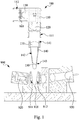
- Fig. 1 is a cross-sectional view of an optical calibration tool 100 and a real-time quantitative polymerase chain reaction (qPCR) instrument 900 before assembly according to an embodiment of the present disclosure.
- Fig. 2A is a cross-sectional view of the optical calibration tool 100 and the qPCR instrument 900 in Fig. 1 after assembly.
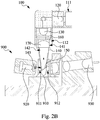
- Fig. 2B is another cross-sectional view of the optical calibration tool 100 and the qPCR instrument 900 in Fig. 2A .
- the optical calibration tool 100 is applied to the qPCR instrument 900.
- the qPCR instrument 900 includes an inspection slot 910, a light emitter 920, and a light receiver 930.
- the inspection slot 910 has a light incident region 911 and a light exit region 912.
- an inspector may place a sample (for example, accommodated in a transparent container) in the inspection slot 910, emit light through the light incident region 911 of the inspection slot 910 to the sample by the light emitter 920, and receives the light passing through the sample through the light exit region 912 of the inspection slot 910 by the light receiver 930.
- the inspector can obtain the physical, chemical, or biological characteristics or parameters of the sample according to the light receiving signal of the light receiver 930.
- the optical calibration tool 100 is used to inspect whether the light emitter 920 and the light receiver 930 of the qPCR instrument 900 are abnormal.
- the optical calibration tool 100 includes a first body 110, a light emitter 120, a light receiver 130, a second body 140, and a light reflecting member 150.
- the first body 110 has a first engaging port 111 and a second engaging port 112.
- the light emitter 120 and the light receiver 130 are disposed in the first body 110.
- the second body 140 has a third engaging port 141 and a channel 142 communicated with each other.
- the third engaging port 141 is configured to engage the first engaging port 111 (as shown in Fig. 2A ) or the second engaging port 112 (as shown in Fig. 2B ).
- the light reflecting member 150 is disposed in the channel 142 and configured to be selectively optically coupled to one of the light incident region 911 and the light exit region 912 of the inspection slot 910 as the second body 140 rotates relative to the inspection slot 910.
- the third engaging port 141 when the third engaging port 141 is engaged with the first engaging port 111, the first engaging port 111 is sleeved on the outer edge of the third engaging port 141, as shown in Fig. 2A , but the present disclosure is not limited in this regard.
- the third engaging port 141 when the third engaging port 141 is engaged with the second engaging port 112, the second engaging port 112 is sleeved on the outer edge of the third engaging port 141, as shown in Fig. 2B , but the present disclosure is not limited in this regard.
- the light emitter 120 of the optical calibration tool 100 is optically coupled to the light reflecting member 150.
- the light emitted by the light emitter 120 of the optical calibration tool 100 can be reflected by the light reflecting member 150 to the light receiver 930 of the qPCR instrument 900.
- a user can determine whether the light receiver 930 of the qPCR instrument 900 is abnormal and needs to be calibrated according to the received light signal.
- the third engaging port 141 is engaged with the second engaging port 112
- the light receiver 130 of the optical calibration tool 100 is optically coupled to the light reflecting member 150.
- the light emitted by the light emitter 920 of the qPCR instrument 900 can be reflected by the light reflecting member 150 to the light receiver 130 of the optical calibration tool 100.
- the user can determine whether the light emitter 920 of the qPCR instrument 900 is abnormal and needs to be calibrated according to the received light signal.
- the light reflecting member 150 is a reflective coating located in the channel 142 and at the bottom of the second body 140, but the present disclosure is not limited in this regard. In some embodiments, the light reflecting member 150 is a metal layer, but the present disclosure is not limited in this regard.
- the second body 140 has a light transmitting portion 143 adjoining the channel 142.
- the light emitter 120 of the optical calibration tool 100 is optically coupled to the light receiver 930 of the qPCR instrument 900 sequentially via the light reflecting member 150 and the light transmitting portion 143.
- Fig. 2A when the third engaging port 141 is engaged with the first engaging port 111 and the light transmitting portion 143 is aligned with the light exit region 912, the light emitter 120 of the optical calibration tool 100 is optically coupled to the light receiver 930 of the qPCR instrument 900 sequentially via the light reflecting member 150 and the light transmitting portion 143.
- the light receiver 130 of the optical calibration tool 100 is optically coupled to the light emitter 920 of the qPCR instrument 900 sequentially via the light reflecting member 150 and the light transmitting portion 143.
- the light transmitting portion 143 is a hole but the present disclosure is not limited in this regard. In some other embodiments, the light transmitting portion 143 includes a transparent material, such as glass, optical-grade polymer, ceramic, or the like.
- the optical calibration tool 100 further includes a neutral density filter 160.
- the neutral density filter 160 is disposed in the first body 110 and adjoins the second engaging port 112. With the arrangement of the neutral density filter 160, the intensity of the light received by the light receiver 130 of the optical calibration tool 100 from the light emitter 920 of the qPCR instrument 900 can be appropriately reduced.
- the material of the second body 140 includes black anodized aluminum to reduce light scattering in the channel 142, but the present disclosure is not limited in this regard.
- the optical calibration tool 100 further includes a lens group 170.
- the lens group 170 is disposed in the channel 142 and adjoins the third engaging port 141.
- the lens group 170 can converge and focus the light emitted by the light emitter 120 of the optical calibration tool 100 to the light receiver 930 of the qPCR instrument 900.
- the lens group 170 can converge and focus the light emitted by the light emitter 920 of the qPCR instrument 900 to the light receiver 130 of the optical calibration tool 100.
- the material of the lens group 170 includes glass, optical-grade polymer, ceramic, or the like.
- numbers of the inspection slot(s) 910, the light emitter(s) 920, and the light receiver(s) 930 of the qPCR instrument 900 are plural and consistent. In some embodiments, numbers of the light emitter(s) 120 of the optical calibration tool 100 and the light receiver(s) 930 of the qPCR instrument 900 are consistent. In some embodiments, a number of the light emitter(s) 120 of the optical calibration tool 100 is smaller than a number of the light receiver(s) 930 of the qPCR instrument 900. In some embodiments, numbers of the light receiver(s) 130 of the optical calibration tool 100 and the light emitter(s) 920 of the qPCR instrument 900 are consistent.
- the light emitter 120 of the optical calibration tool 100 is a light emitting diode or a laser, but the present disclosure is not limited in this regard.
- Fig. 3A is a cross-sectional view of an optical calibration tool 200 and the qPCR instrument 900 after assembly according to an embodiment of the present disclosure.
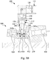
- Fig. 3B is another cross-sectional view of the optical calibration tool 200 and the qPCR instrument 900 in Fig. 3A .
- the second body 240 of the optical calibration tool 200 of this embodiment has two light transmitting portions 243a, 243b.
- the light transmitting portions 243a, 243b are respectively located at opposite sides of the second body 240.
- the light reflecting member 250 is located between the light transmitting portions 243a, 243b.
- the optical calibration tool 200 of this embodiment further includes an actuating member 280.
- the actuating member 280 is configured to rotate the light reflecting member 250.
- the light reflecting member 250 can be rotated by the actuating member 280 such that the light emitter 120 of the optical calibration tool 200 is optically coupled to the light receiver 930 of the qPCR instrument 900 sequentially via the light reflecting member 250 and the light transmitting portion 243a.
- Fig. 3A when the third engaging port 141 is engaged with the first engaging port 111, the light reflecting member 250 can be rotated by the actuating member 280 such that the light emitter 120 of the optical calibration tool 200 is optically coupled to the light receiver 930 of the qPCR instrument 900 sequentially via the light reflecting member 250 and the light transmitting portion 243a.
- the light reflecting member 250 can be rotated by the actuating member 280 such that the light receiver 130 of the optical calibration tool 200 is optically coupled to the light emitter 920 of the qPCR instrument 900 sequentially via the light reflecting member 250 and the light transmitting portion 243b.
- the user only needs to use the actuating member 280 to rotate the light reflecting member 250 to inspect the light emitter 920 and the light receiver 930 of the qPCR instrument 900 without plugging or rotating the second body 240 relative to the inspection slot 910, so that the calibration process can be performed quickly.
- the light reflecting member 250 is a reflector, but the present disclosure is not limited in this regard.
- Fig. 4A is a cross-sectional view of an optical calibration tool 300 and the qPCR instrument 900 after assembly according to an embodiment of the present disclosure.
- Fig. 4B is another cross-sectional view of the optical calibration tool 300 and the qPCR instrument 900 in Fig. 4A .
- one difference between this embodiment and the embodiment shown in Fig. 3A is that the optical calibration tool 300 of this embodiment uses different a light reflecting member 350 and an actuation member 380.
- the actuating member 380 is configured to deform the light reflecting member 350.
- the actuating member 380 can be used to apply force to deform and bend the light reflecting member 350 (for example, to apply a force to the center of the light reflecting member 350 to the right), such that the light emitter 120 of the optical calibration tool 300 is optically coupled to the light receiver 930 of the qPCR instrument 900 sequentially via the light reflecting member 350 and the light transmitting portion 243a.
- the actuating member 380 can be used to apply force to deform and bend the light reflecting member 350 (for example, to apply a force to the center of the light reflecting member 350 to the right), such that the light emitter 120 of the optical calibration tool 300 is optically coupled to the light receiver 930 of the qPCR instrument 900 sequentially via the light reflecting member 350 and the light transmitting portion 243a.
- the actuating member 380 can be used to apply force to deform and bend the light reflecting member 350 (for example, to apply a force to the center of the light reflecting member 350 to the left), such that the light receiver 130 of the optical calibration tool 300 is optically coupled to the light emitter 920 of the qPCR instrument 900 sequentially via the light reflecting member 350 and the light transmitting portion 243b.
- the user only needs to use the actuating member 380 to deform the light reflecting member 350 to inspect the light emitter 920 and the light receiver 930 of the qPCR instrument 900 without plugging or rotating the second body 240 relative to the inspection slot 910, so that the calibration process can be performed quickly.
- the light reflecting member 350 may be a flexible reflective sheet, but the present disclosure is not limited in this regard.
- Fig. 5A is a cross-sectional view of an optical calibration tool 400 and the qPCR instrument 900 after assembly according to an embodiment of the present disclosure.
- Fig. 5B is another cross-sectional view of the optical calibration tool 400 and the qPCR instrument 900 in Fig. 5A .
- Fig. 6 is a schematic diagram of a light reflecting member 450 in Fig. 5A .
- the optical calibration tool 400 of this embodiment replaces the light reflecting member 250 and the actuating member 280 shown in Fig. 3A with the different light reflecting member 450.
- the light reflecting member 450 includes a prism 451 and a light splitting layer 452.
- the bottom of the prism 451 has two surfaces connected to each other. The surfaces are arranged between the light transmitting portions 243a, 243b.
- the light splitting layer 452 covers the surfaces.
- the light splitting layer 452 is a semi-transmissive and semi-reflective film layer. As shown in Fig.
- the light emitted by the light emitter 120 of the optical calibration tool 400 can first enter the prism 451, be partially reflected by the left half of the light splitting layer 452, and then be partially transmitted through the right half of the light splitting layer 452 to reach the light receiver 930 of the qPCR instrument 900. As shown in Fig.
- the light emitted by the light emitter 920 of the qPCR instrument 900 can first be partially transmitted through the left half of the light splitting layer 452enter the prism 451, be partially reflected by the right half of the light splitting layer 452, and then transmit through the prism 451 to reach the light receiver 130 of the optical calibration tool 400.
- the user can inspect the light emitter 920 and the light receiver 930 of the qPCR instrument 900 without plugging or rotating the second body 240 relative to the inspection slot 910, so that the calibration process can be performed quickly.
- the optical calibration tool of the present disclosure by engaging the third engaging port of the second body to the first engaging port of the first body, the light emitter in the optical calibration tool can be used to calibrate the light receiver in the qPCR instrument.
- the light receiver in the optical calibration tool can be used to calibrate the light emitter in the qPCR instrument. That is, the optical calibration tool of the present disclosure can form different functional modules by different combinations of the first body and the second body.
- the optical calibration tool of the present disclosure is easy for the user to operate, so that the calibration procedure can be performed quickly.
Landscapes
- Chemical & Material Sciences (AREA)
- Physics & Mathematics (AREA)
- Health & Medical Sciences (AREA)
- Life Sciences & Earth Sciences (AREA)
- Biochemistry (AREA)
- General Health & Medical Sciences (AREA)
- Immunology (AREA)
- General Physics & Mathematics (AREA)
- Analytical Chemistry (AREA)
- Pathology (AREA)
- Chemical Kinetics & Catalysis (AREA)
- Engineering & Computer Science (AREA)
- Organic Chemistry (AREA)
- Molecular Biology (AREA)
- Proteomics, Peptides & Aminoacids (AREA)
- Optics & Photonics (AREA)
- Zoology (AREA)
- Wood Science & Technology (AREA)
- Nuclear Medicine, Radiotherapy & Molecular Imaging (AREA)
- Clinical Laboratory Science (AREA)
- Biotechnology (AREA)
- Biophysics (AREA)
- Spectroscopy & Molecular Physics (AREA)
- Microbiology (AREA)
- Theoretical Computer Science (AREA)
- Mathematical Physics (AREA)
- Geometry (AREA)
- Bioinformatics & Cheminformatics (AREA)
- General Engineering & Computer Science (AREA)
- Genetics & Genomics (AREA)
- Investigating Or Analysing Materials By Optical Means (AREA)
- Photometry And Measurement Of Optical Pulse Characteristics (AREA)
- Apparatus Associated With Microorganisms And Enzymes (AREA)
Abstract
Description
- The present disclosure relates to an optical calibration tool.
- One conventional approach of calibrating a real-time quantitative polymerase chain reaction (qPCR) instrument is using fluorescence calibration kit samples. However, there are many disadvantages due to its inherent properties. Typically, the fluorescent calibration kit samples have to be stored under room temperature, and the life of shelf is very short once the kit is unsealed. Typically, the shelf life suppliers suggested are usually 6 months. Also, repeated thawing process between room temperature and freezing temperature cause the degradation of fluorescent calibration kit.
- Accordingly, how to provide an optical calibration tool to solve the aforementioned problems becomes an important issue to be solved by those in the industry.
- An aspect of the disclosure is to provide an optical calibration tool which can effectively solve the aforementioned problems.
- According to an embodiment of the disclosure, an optical calibration tool includes a first body, a light emitter, a light receiver, a second body, and a light reflecting member. The first body has a first engaging port and a second engaging port. The light emitter and the light receiver are disposed in the first body. The second body has a third engaging port and a channel communicated with each other. The third engaging port is configured to selectively engage one of the first engaging port and the second engaging port. When the third engaging port is engaged with the first engaging port, the light emitter is optically coupled to the light reflecting member. When the third engaging port is engaged with the second engaging port, the light receiver is optically coupled to the light reflecting member.
- In an embodiment of the disclosure, the second body has a light transmitting portion adjoining the channel. When the third engaging port is engaged with the first engaging port, the light emitter is optically coupled to the light transmitting portion via the light reflecting member. When the third engaging port is engaged with the second engaging port, the light receiver is optically coupled to the light transmitting portion via the light reflecting member.
- In an embodiment of the disclosure, the light transmitting portion is a hole.
- In an embodiment of the disclosure, the second body has two light transmitting portions. Said two light transmitting portions are respectively located at opposite sides of the second body. The light reflecting member is located between said two light transmitting portions.
- In an embodiment of the disclosure, the optical calibration tool further includes an actuating member. The actuating member is configured to rotate the light reflecting member.
- In an embodiment of the disclosure, the optical calibration tool further includes an actuating member. The actuating member is configured to deform the light reflecting member.
- In an embodiment of the disclosure, the light reflecting member includes a prism and a light splitting layer. The prism has two surfaces connected to each other and arranged between said two light transmitting portions. The light splitting layer covers said two surfaces.
- In an embodiment of the disclosure, the optical calibration tool further includes a neutral density filter. The neutral density filter is disposed in the first body and adjoins the second engaging port.
- In an embodiment of the disclosure, the optical calibration tool further includes a lens group. The lens group is disposed in the channel and adjoins the third engaging port.
- According to an embodiment of the disclosure, an optical calibration tool is applied to a real-time quantitative polymerase chain reaction (qPCR) instrument. The qPCR instrument includes an inspection slot. The inspection slot has a light incident region and a light exit region. The optical calibration tool includes a first body, a light emitter, a light receiver, a second body, and a light reflecting member. The first body has a first engaging port and a second engaging port. The light emitter is disposed in the first body. The light receiver is disposed in the first body. The second body has a third engaging port and a channel communicated with each other. The third engaging port is configured to selectively engage one of the first engaging port and the second engaging port. The light reflecting member is disposed in the channel and configured to be selectively optically coupled to one of the light incident region and the light exit region as the second body rotates relative to the inspection slot.
- Accordingly, in the optical calibration tool of the present disclosure, by engaging the third engaging port of the second body to the first engaging port of the first body, the light emitter in the optical calibration tool can be used to calibrate the light receiver in the qPCR instrument. Relatively, by engaging the third engaging port of the second body to the second engaging port of the first body, the light receiver in the optical calibration tool can be used to calibrate the light emitter in the qPCR instrument. That is, the optical calibration tool of the present disclosure can form different functional modules by different combinations of the first body and the second body. Furthermore, a user only needs to insert the second body into the inspection slot of the qPCR instrument to optically couple the light emitter of the optical calibration tool to the light receiver in the qPCR instrument, or to optically couple the light receiver of the optical calibration tool to the light emitter in the qPCR instrument. As such, the optical calibration tool of the present disclosure is easy for the user to operate, so that the calibration procedure can be performed quickly.
- It is to be understood that both the foregoing general description and the following detailed description are by examples, and are intended to provide further explanation of the disclosure as claimed.
- The disclosure can be more fully understood by reading the following detailed description of the embodiment, with reference made to the accompanying drawings as follows:
-
Fig. 1 is a cross-sectional view of an optical calibration tool and a real-time quantitative polymerase chain reaction (qPCR) instrument before assembly according to an embodiment of the present disclosure; -
Fig. 2A is a cross-sectional view of the optical calibration tool and the qPCR instrument inFig. 1 after assembly; -
Fig. 2B is another cross-sectional view of the optical calibration tool and the qPCR instrument inFig. 2A ; -
Fig. 3A is a cross-sectional view of an optical calibration tool and the qPCR instrument after assembly according to an embodiment of the present disclosure; -
Fig. 3B is another cross-sectional view of the optical calibration tool and the qPCR instrument inFig. 3A ; -
Fig. 4A is a cross-sectional view of an optical calibration tool and the qPCR instrument after assembly according to an embodiment of the present disclosure; -
Fig. 4B is another cross-sectional view of the optical calibration tool and the qPCR instrument inFig. 4A ; -
Fig. 5A is a cross-sectional view of an optical calibration tool and the qPCR instrument after assembly according to an embodiment of the present disclosure; -
Fig. 5B is another cross-sectional view of the optical calibration tool and the qPCR instrument inFig. 5A ; and -
Fig. 6 is a schematic diagram of a light reflecting member inFig. 5A . - Reference will now be made in detail to the present embodiments of the disclosure, examples of which are illustrated in the accompanying drawings. Wherever possible, the same reference numbers are used in the drawings and the description to refer to the same or like parts. However, specific structural and functional details disclosed herein are merely representative for purposes of describing example embodiments, and thus may be embodied in many alternate forms and should not be construed as limited to only example embodiments set forth herein. Therefore, it should be understood that there is no intent to limit example embodiments to the particular forms disclosed, but on the contrary, example embodiments are to cover all modifications, equivalents, and alternatives falling within the scope of the disclosure.
- Reference is made to
Figs. 1 to 2B .Fig. 1 is a cross-sectional view of anoptical calibration tool 100 and a real-time quantitative polymerase chain reaction (qPCR)instrument 900 before assembly according to an embodiment of the present disclosure.Fig. 2A is a cross-sectional view of theoptical calibration tool 100 and theqPCR instrument 900 inFig. 1 after assembly.Fig. 2B is another cross-sectional view of theoptical calibration tool 100 and theqPCR instrument 900 inFig. 2A . As shown inFigs. 1 to 2B , in the present embodiment, theoptical calibration tool 100 is applied to theqPCR instrument 900. TheqPCR instrument 900 includes aninspection slot 910, alight emitter 920, and alight receiver 930. Theinspection slot 910 has alight incident region 911 and alight exit region 912. When theqPCR instrument 900 is working, an inspector may place a sample (for example, accommodated in a transparent container) in theinspection slot 910, emit light through thelight incident region 911 of theinspection slot 910 to the sample by thelight emitter 920, and receives the light passing through the sample through thelight exit region 912 of theinspection slot 910 by thelight receiver 930. Hence, the inspector can obtain the physical, chemical, or biological characteristics or parameters of the sample according to the light receiving signal of thelight receiver 930. Theoptical calibration tool 100 is used to inspect whether thelight emitter 920 and thelight receiver 930 of theqPCR instrument 900 are abnormal. - The
optical calibration tool 100 includes afirst body 110, alight emitter 120, alight receiver 130, asecond body 140, and alight reflecting member 150. Thefirst body 110 has a firstengaging port 111 and a secondengaging port 112. Thelight emitter 120 and thelight receiver 130 are disposed in thefirst body 110. Thesecond body 140 has a thirdengaging port 141 and achannel 142 communicated with each other. The thirdengaging port 141 is configured to engage the first engaging port 111 (as shown inFig. 2A ) or the second engaging port 112 (as shown inFig. 2B ). Thelight reflecting member 150 is disposed in thechannel 142 and configured to be selectively optically coupled to one of thelight incident region 911 and thelight exit region 912 of theinspection slot 910 as thesecond body 140 rotates relative to theinspection slot 910. - In some embodiments, when the third
engaging port 141 is engaged with the first engagingport 111, the first engagingport 111 is sleeved on the outer edge of the thirdengaging port 141, as shown inFig. 2A , but the present disclosure is not limited in this regard. In some embodiments, when the thirdengaging port 141 is engaged with the secondengaging port 112, the secondengaging port 112 is sleeved on the outer edge of the thirdengaging port 141, as shown inFig. 2B , but the present disclosure is not limited in this regard. - Specifically, as shown in
Fig. 2A , when the thirdengaging port 141 is engaged with the first engagingport 111, thelight emitter 120 of theoptical calibration tool 100 is optically coupled to thelight reflecting member 150. In other words, the light emitted by thelight emitter 120 of theoptical calibration tool 100 can be reflected by thelight reflecting member 150 to thelight receiver 930 of theqPCR instrument 900. Hence, a user can determine whether thelight receiver 930 of theqPCR instrument 900 is abnormal and needs to be calibrated according to the received light signal. As shown inFig. 2B , when the thirdengaging port 141 is engaged with the secondengaging port 112, thelight receiver 130 of theoptical calibration tool 100 is optically coupled to thelight reflecting member 150. In other words, the light emitted by thelight emitter 920 of theqPCR instrument 900 can be reflected by thelight reflecting member 150 to thelight receiver 130 of theoptical calibration tool 100. Hence, the user can determine whether thelight emitter 920 of theqPCR instrument 900 is abnormal and needs to be calibrated according to the received light signal. - In some embodiments, the
light reflecting member 150 is a reflective coating located in thechannel 142 and at the bottom of thesecond body 140, but the present disclosure is not limited in this regard. In some embodiments, thelight reflecting member 150 is a metal layer, but the present disclosure is not limited in this regard. - In some embodiments, the
second body 140 has alight transmitting portion 143 adjoining thechannel 142. As shown inFig. 2A , when the thirdengaging port 141 is engaged with the first engagingport 111 and thelight transmitting portion 143 is aligned with thelight exit region 912, thelight emitter 120 of theoptical calibration tool 100 is optically coupled to thelight receiver 930 of theqPCR instrument 900 sequentially via thelight reflecting member 150 and thelight transmitting portion 143. As shown inFig. 2B , when the thirdengaging port 141 is engaged with the secondengaging port 112 and thelight transmitting portion 143 is aligned with thelight incident region 911, thelight receiver 130 of theoptical calibration tool 100 is optically coupled to thelight emitter 920 of theqPCR instrument 900 sequentially via thelight reflecting member 150 and thelight transmitting portion 143. - In some embodiments, the
light transmitting portion 143 is a hole but the present disclosure is not limited in this regard. In some other embodiments, thelight transmitting portion 143 includes a transparent material, such as glass, optical-grade polymer, ceramic, or the like. - In some embodiments, as shown in
Fig. 2B , theoptical calibration tool 100 further includes aneutral density filter 160. Theneutral density filter 160 is disposed in thefirst body 110 and adjoins the secondengaging port 112. With the arrangement of theneutral density filter 160, the intensity of the light received by thelight receiver 130 of theoptical calibration tool 100 from thelight emitter 920 of theqPCR instrument 900 can be appropriately reduced. - In some embodiments, the material of the
second body 140 includes black anodized aluminum to reduce light scattering in thechannel 142, but the present disclosure is not limited in this regard. - In some embodiments, as shown in
Figs. 2A and2B , theoptical calibration tool 100 further includes alens group 170. Thelens group 170 is disposed in thechannel 142 and adjoins the thirdengaging port 141. When thelight emitter 120 ofoptical calibration tool 100 is optically coupled to thelight receiver 930 of the qPCR instrument 900 (as shown inFig. 2A ), thelens group 170 can converge and focus the light emitted by thelight emitter 120 of theoptical calibration tool 100 to thelight receiver 930 of theqPCR instrument 900. When thelight receiver 130 of theoptical calibration tool 100 is optically coupled to thelight emitter 920 of the qPCR instrument 900 (as shown inFig. 2B ), thelens group 170 can converge and focus the light emitted by thelight emitter 920 of theqPCR instrument 900 to thelight receiver 130 of theoptical calibration tool 100. - In some other embodiments, the material of the
lens group 170 includes glass, optical-grade polymer, ceramic, or the like. - In some embodiments, numbers of the inspection slot(s) 910, the light emitter(s) 920, and the light receiver(s) 930 of the
qPCR instrument 900 are plural and consistent. In some embodiments, numbers of the light emitter(s) 120 of theoptical calibration tool 100 and the light receiver(s) 930 of theqPCR instrument 900 are consistent. In some embodiments, a number of the light emitter(s) 120 of theoptical calibration tool 100 is smaller than a number of the light receiver(s) 930 of theqPCR instrument 900. In some embodiments, numbers of the light receiver(s) 130 of theoptical calibration tool 100 and the light emitter(s) 920 of theqPCR instrument 900 are consistent. - In some embodiments, the
light emitter 120 of theoptical calibration tool 100 is a light emitting diode or a laser, but the present disclosure is not limited in this regard. - Reference is made to
Figs. 3A and3B .Fig. 3A is a cross-sectional view of anoptical calibration tool 200 and theqPCR instrument 900 after assembly according to an embodiment of the present disclosure.Fig. 3B is another cross-sectional view of theoptical calibration tool 200 and theqPCR instrument 900 inFig. 3A . As shown inFigs. 3A and3B , one difference between this embodiment and the embodiment shown inFig. 2A is that thesecond body 240 of theoptical calibration tool 200 of this embodiment has twolight transmitting portions light transmitting portions second body 240. Thelight reflecting member 250 is located between thelight transmitting portions - Another difference between this embodiment and the embodiment shown in
Fig. 2A is that theoptical calibration tool 200 of this embodiment further includes an actuatingmember 280. The actuatingmember 280 is configured to rotate thelight reflecting member 250. As shown inFig. 3A , when the thirdengaging port 141 is engaged with the first engagingport 111, thelight reflecting member 250 can be rotated by the actuatingmember 280 such that thelight emitter 120 of theoptical calibration tool 200 is optically coupled to thelight receiver 930 of theqPCR instrument 900 sequentially via thelight reflecting member 250 and thelight transmitting portion 243a. As shown inFig. 3B , when the thirdengaging port 141 is engaged with the secondengaging port 112, thelight reflecting member 250 can be rotated by the actuatingmember 280 such that thelight receiver 130 of theoptical calibration tool 200 is optically coupled to thelight emitter 920 of theqPCR instrument 900 sequentially via thelight reflecting member 250 and thelight transmitting portion 243b. Hence, the user only needs to use the actuatingmember 280 to rotate thelight reflecting member 250 to inspect thelight emitter 920 and thelight receiver 930 of theqPCR instrument 900 without plugging or rotating thesecond body 240 relative to theinspection slot 910, so that the calibration process can be performed quickly. - In some embodiments, the
light reflecting member 250 is a reflector, but the present disclosure is not limited in this regard. - Reference is made to
Figs. 4A and4B .Fig. 4A is a cross-sectional view of anoptical calibration tool 300 and theqPCR instrument 900 after assembly according to an embodiment of the present disclosure.Fig. 4B is another cross-sectional view of theoptical calibration tool 300 and theqPCR instrument 900 inFig. 4A . As shown inFigs. 4A and4B , one difference between this embodiment and the embodiment shown inFig. 3A is that theoptical calibration tool 300 of this embodiment uses different alight reflecting member 350 and anactuation member 380. - Specifically, the actuating
member 380 is configured to deform thelight reflecting member 350. As shown inFig. 4A , when the thirdengaging port 141 is engaged with the first engagingport 111, the actuatingmember 380 can be used to apply force to deform and bend the light reflecting member 350 (for example, to apply a force to the center of thelight reflecting member 350 to the right), such that thelight emitter 120 of theoptical calibration tool 300 is optically coupled to thelight receiver 930 of theqPCR instrument 900 sequentially via thelight reflecting member 350 and thelight transmitting portion 243a. As shown inFig. 4B , when the thirdengaging port 141 is engaged with the secondengaging port 112, the actuatingmember 380 can be used to apply force to deform and bend the light reflecting member 350 (for example, to apply a force to the center of thelight reflecting member 350 to the left), such that thelight receiver 130 of theoptical calibration tool 300 is optically coupled to thelight emitter 920 of theqPCR instrument 900 sequentially via thelight reflecting member 350 and thelight transmitting portion 243b. Hence, the user only needs to use the actuatingmember 380 to deform thelight reflecting member 350 to inspect thelight emitter 920 and thelight receiver 930 of theqPCR instrument 900 without plugging or rotating thesecond body 240 relative to theinspection slot 910, so that the calibration process can be performed quickly. - In some embodiments, the
light reflecting member 350 may be a flexible reflective sheet, but the present disclosure is not limited in this regard. - Reference is made to
Figs. 5A to 6 .Fig. 5A is a cross-sectional view of anoptical calibration tool 400 and theqPCR instrument 900 after assembly according to an embodiment of the present disclosure.Fig. 5B is another cross-sectional view of theoptical calibration tool 400 and theqPCR instrument 900 inFig. 5A .Fig. 6 is a schematic diagram of alight reflecting member 450 inFig. 5A . As shown inFigs. 5A to 6 , one difference between this embodiment and the embodiment shown inFigs. 3A is that theoptical calibration tool 400 of this embodiment replaces thelight reflecting member 250 and the actuatingmember 280 shown inFig. 3A with the differentlight reflecting member 450. - Specifically, as shown in
Fig. 6 , thelight reflecting member 450 includes aprism 451 and alight splitting layer 452. The bottom of theprism 451 has two surfaces connected to each other. The surfaces are arranged between thelight transmitting portions light splitting layer 452 covers the surfaces. In some embodiments, thelight splitting layer 452 is a semi-transmissive and semi-reflective film layer. As shown inFig. 5A , when the thirdengaging port 141 is engaged with the first engagingport 111, the light emitted by thelight emitter 120 of theoptical calibration tool 400 can first enter theprism 451, be partially reflected by the left half of thelight splitting layer 452, and then be partially transmitted through the right half of thelight splitting layer 452 to reach thelight receiver 930 of theqPCR instrument 900. As shown inFig. 5B , when the thirdengaging port 141 is engaged with the secondengaging port 112, the light emitted by thelight emitter 920 of theqPCR instrument 900 can first be partially transmitted through the left half of the light splitting layer 452enter theprism 451, be partially reflected by the right half of thelight splitting layer 452, and then transmit through theprism 451 to reach thelight receiver 130 of theoptical calibration tool 400. Hence, the user can inspect thelight emitter 920 and thelight receiver 930 of theqPCR instrument 900 without plugging or rotating thesecond body 240 relative to theinspection slot 910, so that the calibration process can be performed quickly. - According to the foregoing recitations of the embodiments of the disclosure, it can be seen that in the optical calibration tool of the present disclosure, by engaging the third engaging port of the second body to the first engaging port of the first body, the light emitter in the optical calibration tool can be used to calibrate the light receiver in the qPCR instrument. Relatively, by engaging the third engaging port of the second body to the second engaging port of the first body, the light receiver in the optical calibration tool can be used to calibrate the light emitter in the qPCR instrument. That is, the optical calibration tool of the present disclosure can form different functional modules by different combinations of the first body and the second body. Furthermore, a user only needs to insert the second body into the inspection slot of the qPCR instrument to optically couple the light emitter of the optical calibration tool to the light receiver in the qPCR instrument, or to optically couple the light receiver of the optical calibration tool to the light emitter in the qPCR instrument. As such, the optical calibration tool of the present disclosure is easy for the user to operate, so that the calibration procedure can be performed quickly.
Claims (10)
- An optical calibration tool (100), comprising:a first body (110) having a first engaging port (111) and a second engaging port (112);a light emitter (920) disposed in the first body (110);a light receiver (930) disposed in the first body (110);a second body (140) having a third engaging port (141) and a channel (142) communicated with each other, wherein the third engaging port (141) is configured to selectively engage one of the first engaging port (111) and the second engaging port (112); anda light reflecting member (150) disposed in the channel (142),wherein when the third engaging port (141) is engaged with the first engaging port (111), the light emitter (920) is optically coupled to the light reflecting member (150), and when the third engaging port (141) is engaged with the second engaging port (112), the light receiver (930) is optically coupled to the light reflecting member (150).
- The optical calibration tool (100) of claim 1, wherein the second body (140) has a light transmitting portion (143) adjoining the channel (142), when the third engaging port (141) is engaged with the first engaging port (111), the light emitter (920) is optically coupled to the light transmitting portion (143) via the light reflecting member (150), and when the third engaging port (141) is engaged with the second engaging port (112), the light receiver (930) is optically coupled to the light transmitting portion (143) via the light reflecting member (150).
- The optical calibration tool (100) of claim 1 or 2, wherein the light transmitting portion (143) is a hole.
- The optical calibration tool (100) of any of claims 1 to 3, wherein the second body (240) has two light transmitting portions (243a, 243b) respectively located at opposite sides of the second body (240), and the light reflecting member (250) is located between said two light transmitting portions (243a, 243b).
- The optical calibration tool (100) of any of claims 1 to 4, further comprising an actuating member (280) configured to rotate the light reflecting member (250).
- The optical calibration tool (100) of any of claims 1 to 4, further comprising an actuating member (380) configured to deform the light reflecting member (350).
- The optical calibration tool (100) of any of claims 1 to 4, wherein the light reflecting member (450) comprises:a prism (451) having two surfaces connected to each other and arranged between said two light transmitting portions (243a, 243b); anda light splitting layer (452) covering said two surfaces.
- The optical calibration tool (100) of any of claims 1 to 7, further comprising a neutral density filter (160) disposed in the first body (110) and adjoining the second engaging port (112).
- The optical calibration tool (100) of any of claims 1 to 8, further comprising a lens group (170) disposed in the channel (142) and adjoining the third engaging port (141).
- An optical calibration tool (100) applied to a real-time quantitative polymerase chain reaction (qPCR) instrument (900), the qPCR instrument (900) comprising an inspection slot (910), the inspection slot (910) having a light incident region (911) and a light exit region (912), the optical calibration tool (100) comprising:a first body (110) having a first engaging port (111) and a second engaging port (112);a light emitter (920) disposed in the first body (110);a light receiver (930) disposed in the first body (110);a second body (140) having a third engaging port (141) and a channel (142) communicated with each other, wherein the third engaging port (141) is configured to selectively engage one of the first engaging port (111) and the second engaging port (112); anda light reflecting member (150) disposed in the channel (142) and configured to be selectively optically coupled to one of the light incident region (911) and the light exit region (912) as the second body (140) rotates relative to the inspection slot (910).
Applications Claiming Priority (1)
| Application Number | Priority Date | Filing Date | Title |
|---|---|---|---|
| TW109102937A TWI722785B (en) | 2020-01-31 | 2020-01-31 | Optical calibration tool |
Publications (3)
| Publication Number | Publication Date |
|---|---|
| EP3859309A1 true EP3859309A1 (en) | 2021-08-04 |
| EP3859309B1 EP3859309B1 (en) | 2024-11-06 |
| EP3859309C0 EP3859309C0 (en) | 2024-11-06 |
Family
ID=72708996
Family Applications (1)
| Application Number | Title | Priority Date | Filing Date |
|---|---|---|---|
| EP20198970.4A Active EP3859309B1 (en) | 2020-01-31 | 2020-09-29 | Optical calibration tool |
Country Status (6)
| Country | Link |
|---|---|
| US (2) | US11815445B2 (en) |
| EP (1) | EP3859309B1 (en) |
| JP (1) | JP6992943B2 (en) |
| CN (2) | CN113201448B (en) |
| ES (1) | ES3005585T3 (en) |
| TW (1) | TWI722785B (en) |
Families Citing this family (1)
| Publication number | Priority date | Publication date | Assignee | Title |
|---|---|---|---|---|
| TWI722785B (en) * | 2020-01-31 | 2021-03-21 | 台達電子工業股份有限公司 | Optical calibration tool |
Citations (5)
| Publication number | Priority date | Publication date | Assignee | Title |
|---|---|---|---|---|
| US3645627A (en) * | 1969-04-14 | 1972-02-29 | Melpar Inc | Calibration system for photodetecting instruments |
| JPS63315938A (en) * | 1987-06-19 | 1988-12-23 | Yokogawa Electric Corp | State measuring instrument for material surface |
| US6067156A (en) * | 1997-05-16 | 2000-05-23 | Kaiser Optical Systems | Wavelength calibration and tracking methods and apparatus |
| US6078388A (en) * | 1996-08-19 | 2000-06-20 | I & T Information Et Technologie | Calibration system for spectroscopic detectors |
| US20030117623A1 (en) * | 2001-12-10 | 2003-06-26 | Apprise Technologies, Inc. | Turbidity sensor |
Family Cites Families (46)
| Publication number | Priority date | Publication date | Assignee | Title |
|---|---|---|---|---|
| IL34960A (en) | 1970-07-20 | 1974-11-29 | Rafa Labor Ltd | A method for the determination of pregnancy and a serodiagnostic composition therefor |
| JPS5525380Y1 (en) * | 1976-12-31 | 1980-06-18 | ||
| US7273749B1 (en) | 1990-06-04 | 2007-09-25 | University Of Utah Research Foundation | Container for carrying out and monitoring biological processes |
| US6800452B1 (en) | 1994-08-08 | 2004-10-05 | Science Applications International Corporation | Automated methods for simultaneously performing a plurality of signal-based assays |
| CN101419170A (en) | 1996-08-16 | 2009-04-29 | Ge保健尼亚加拉公司 | A digital imaging system for assays in well plates, gels and blots |
| US6818437B1 (en) | 1998-05-16 | 2004-11-16 | Applera Corporation | Instrument for monitoring polymerase chain reaction of DNA |
| JP2000074837A (en) | 1998-08-31 | 2000-03-14 | Fuji Photo Film Co Ltd | Photographing device |
| US7119345B2 (en) | 2003-02-28 | 2006-10-10 | Applera Corporation | Excitation and emission filter |
| US7410793B2 (en) | 1999-05-17 | 2008-08-12 | Applera Corporation | Optical instrument including excitation source |
| US6518068B1 (en) | 1999-07-21 | 2003-02-11 | Tropix, Inc. | Luminescence detection workstation |
| US6852986B1 (en) | 1999-11-12 | 2005-02-08 | E. I. Du Pont De Nemours And Company | Fluorometer with low heat-generating light source |
| EP1269159A4 (en) | 2000-02-25 | 2005-01-26 | Cambridge Res & Instrmnt Inc | Instantaneous dual band fluorescence detection systems |
| US7015484B2 (en) | 2001-04-16 | 2006-03-21 | Dakota Technologies, Inc. | Multi-dimensional fluorescence apparatus and method for rapid and highly sensitive quantitative analysis of mixtures |
| JP3999479B2 (en) | 2001-07-10 | 2007-10-31 | オリンパス株式会社 | Optical device |
| US6982166B2 (en) | 2002-05-16 | 2006-01-03 | Applera Corporation | Lens assembly for biological testing |
| US7148043B2 (en) | 2003-05-08 | 2006-12-12 | Bio-Rad Laboratories, Inc. | Systems and methods for fluorescence detection with a movable detection module |
| US7102746B2 (en) * | 2003-12-16 | 2006-09-05 | New Chromex, Inc. | Raman spectroscope |
| US7122799B2 (en) | 2003-12-18 | 2006-10-17 | Palo Alto Research Center Incorporated | LED or laser enabled real-time PCR system and spectrophotometer |
| US7295316B2 (en) | 2004-01-14 | 2007-11-13 | Applera Corporation | Fluorescent detector with automatic changing filters |
| JP4141985B2 (en) | 2004-05-19 | 2008-08-27 | 株式会社日立ハイテクノロジーズ | Spectrofluorometer and sample cell |
| US7315376B2 (en) | 2005-01-07 | 2008-01-01 | Advanced Molecular Systems, Llc | Fluorescence detection system |
| ATE359500T1 (en) | 2005-01-18 | 2007-05-15 | Hoffmann La Roche | FLUORESCENCE IMAGING USING TELECENTRICITY |
| ES2284087T3 (en) | 2005-01-18 | 2007-11-01 | F. Hoffmann-La Roche Ag | GENERATION OF FLUORESCENCE SIGNAL IMAGES BY TELECENTRIC EXCITATION AND IMAGE GENERATION OPTICS. |
| CA2842402C (en) * | 2005-03-10 | 2016-02-23 | Gen-Probe Incorporated | Systems and methods to perform assays for detecting or quantifying analytes within samples |
| JP2008541139A (en) | 2005-05-04 | 2008-11-20 | スリーエム イノベイティブ プロパティズ カンパニー | System and method for a pulsed light source used in fluorescence detection |
| CA2610856A1 (en) * | 2005-06-13 | 2006-12-28 | Stratagene California | System and method for fluorescence excitation and detection having distinct optical paths |
| US7663750B2 (en) | 2005-06-30 | 2010-02-16 | Applied Biosystems, Llc | Two-dimensional spectral imaging system |
| US7998708B2 (en) | 2006-03-24 | 2011-08-16 | Handylab, Inc. | Microfluidic system for amplifying and detecting polynucleotides in parallel |
| US8900828B2 (en) | 2006-05-01 | 2014-12-02 | Cepheid | Methods and apparatus for sequential amplification reactions |
| US7414724B2 (en) | 2006-11-17 | 2008-08-19 | Eppendorf Ag | Light diffuser used in a testing apparatus |
| US7700928B2 (en) | 2007-01-25 | 2010-04-20 | Etaluma, Inc. | Apparatus and method for interleaving detection of fluorescence and luminescence |
| US20080277595A1 (en) | 2007-05-10 | 2008-11-13 | Pacific Biosciences Of California, Inc. | Highly multiplexed confocal detection systems and methods of using same |
| CN201837588U (en) | 2009-09-09 | 2011-05-18 | 海利克斯公司 | Optical system for multiple reactions |
| TWM393517U (en) * | 2010-06-29 | 2010-12-01 | Inst Of Occupational Safety And Health Council Of Labor Affairs Executive Yuan | Optical sensing module for polymerase chain reactor |
| US9096892B1 (en) | 2011-02-04 | 2015-08-04 | K2 Biomicrosystems, LLC | Nucleic acid amplification and monitoring apparatus |
| CN104159559B (en) | 2011-11-10 | 2018-01-02 | 拜奥法尔诊断有限责任公司 | Load phial |
| JP6440617B2 (en) | 2012-09-10 | 2018-12-19 | バイオファイア・ダイアグノスティクス,リミテッド・ライアビリティ・カンパニー | Multiple amplification cycle detection |
| US20140273181A1 (en) | 2013-03-15 | 2014-09-18 | Biofire Diagnostics, Inc. | Compact optical system for substantially simultaneous monitoring of samples in a sample array |
| BR112016007781B1 (en) | 2013-10-07 | 2021-12-28 | Douglas Scientific, Llc. | PORTABLE TEST DEVICE FOR ANALYZING BIOLOGICAL SAMPLES |
| CN106291834A (en) * | 2015-05-22 | 2017-01-04 | 鸿富锦精密工业(深圳)有限公司 | Optical communication apparatus |
| TWI575190B (en) * | 2016-03-04 | 2017-03-21 | 光寶電子(廣州)有限公司 | Lens with reduced thickness and optical unit having the same |
| SG10201704313TA (en) * | 2016-09-12 | 2018-04-27 | Delta Electronics Intl Singapore Pte Ltd | Fluorescence Detection Device |
| SG10201609334WA (en) * | 2016-11-08 | 2018-06-28 | Delta Electronics Intl Singapore Pte Ltd | Multi-Channel Fluorescence Detection Device |
| SG10201800240YA (en) | 2018-01-10 | 2019-08-27 | Delta Electronics Int’L Singapore Pte Ltd | Multi-color fluorescence detection device |
| CN108181239B (en) * | 2018-02-07 | 2023-09-12 | 张哲夫 | Optical system of multichannel fluorescence quantitative PCR instrument |
| TWI722785B (en) * | 2020-01-31 | 2021-03-21 | 台達電子工業股份有限公司 | Optical calibration tool |
-
2020
- 2020-01-31 TW TW109102937A patent/TWI722785B/en active
- 2020-02-03 CN CN202010078236.2A patent/CN113201448B/en active Active
- 2020-02-03 CN CN202020150584.1U patent/CN212025349U/en active Active
- 2020-03-31 JP JP2020064965A patent/JP6992943B2/en active Active
- 2020-09-07 US US17/013,840 patent/US11815445B2/en active Active
- 2020-09-29 ES ES20198970T patent/ES3005585T3/en active Active
- 2020-09-29 EP EP20198970.4A patent/EP3859309B1/en active Active
-
2023
- 2023-10-06 US US18/482,027 patent/US12174109B2/en active Active
Patent Citations (5)
| Publication number | Priority date | Publication date | Assignee | Title |
|---|---|---|---|---|
| US3645627A (en) * | 1969-04-14 | 1972-02-29 | Melpar Inc | Calibration system for photodetecting instruments |
| JPS63315938A (en) * | 1987-06-19 | 1988-12-23 | Yokogawa Electric Corp | State measuring instrument for material surface |
| US6078388A (en) * | 1996-08-19 | 2000-06-20 | I & T Information Et Technologie | Calibration system for spectroscopic detectors |
| US6067156A (en) * | 1997-05-16 | 2000-05-23 | Kaiser Optical Systems | Wavelength calibration and tracking methods and apparatus |
| US20030117623A1 (en) * | 2001-12-10 | 2003-06-26 | Apprise Technologies, Inc. | Turbidity sensor |
Also Published As
| Publication number | Publication date |
|---|---|
| CN113201448B (en) | 2025-07-29 |
| TWI722785B (en) | 2021-03-21 |
| ES3005585T3 (en) | 2025-03-14 |
| US20210239600A1 (en) | 2021-08-05 |
| EP3859309B1 (en) | 2024-11-06 |
| TW202130985A (en) | 2021-08-16 |
| US12174109B2 (en) | 2024-12-24 |
| JP6992943B2 (en) | 2022-01-13 |
| CN113201448A (en) | 2021-08-03 |
| CN212025349U (en) | 2020-11-27 |
| EP3859309C0 (en) | 2024-11-06 |
| US11815445B2 (en) | 2023-11-14 |
| US20240035955A1 (en) | 2024-02-01 |
| JP2021122268A (en) | 2021-08-30 |
Similar Documents
| Publication | Publication Date | Title |
|---|---|---|
| US11920979B2 (en) | Optical measurement device including internal spectral reference | |
| US9927685B2 (en) | Illumination system having light-splitting unit and projection apparatus | |
| CN111239093A (en) | Planar miniature multi-channel fluorescence detection optical system | |
| US12174109B2 (en) | Optical calibration tool | |
| JP7230988B2 (en) | Separation of fluid samples in multipass optics | |
| JP2010281808A (en) | Illumination apparatus and reflective characteristic measuring apparatus employing the same | |
| US7285787B2 (en) | Epi-illumination microscope and fluorescence filter set | |
| JPH11326209A (en) | Apparatus for detecting fluorescent dye | |
| CA3099111C (en) | Illumination unit with multiple light sources for generating a uniform illumination spot | |
| EP2565629B1 (en) | Automatic analyzer | |
| CN219016692U (en) | Illumination system and microscope | |
| TWI702397B (en) | Fluorescent microscopic imaging device | |
| CN118817597B (en) | Fluorescence detection device and microfluidic chip detection system | |
| CN1825091B (en) | Reflectance Measuring Device | |
| JP5805259B2 (en) | Automatic analyzer | |
| JP6588083B2 (en) | Aiming system and method | |
| US20240192127A1 (en) | Optical measuring system | |
| JP2010243311A (en) | Spectrometer and cuvette using laser light source | |
| WO2025257136A1 (en) | A calibration cartridge for an optomechanical measuring device | |
| CN119642140A (en) | Multi-band composite light source | |
| JP2000356747A (en) | Illumination device for enlarging observation |
Legal Events
| Date | Code | Title | Description |
|---|---|---|---|
| PUAI | Public reference made under article 153(3) epc to a published international application that has entered the european phase |
Free format text: ORIGINAL CODE: 0009012 |
|
| STAA | Information on the status of an ep patent application or granted ep patent |
Free format text: STATUS: THE APPLICATION HAS BEEN PUBLISHED |
|
| AK | Designated contracting states |
Kind code of ref document: A1 Designated state(s): AL AT BE BG CH CY CZ DE DK EE ES FI FR GB GR HR HU IE IS IT LI LT LU LV MC MK MT NL NO PL PT RO RS SE SI SK SM TR |
|
| STAA | Information on the status of an ep patent application or granted ep patent |
Free format text: STATUS: REQUEST FOR EXAMINATION WAS MADE |
|
| 17P | Request for examination filed |
Effective date: 20220204 |
|
| RBV | Designated contracting states (corrected) |
Designated state(s): AL AT BE BG CH CY CZ DE DK EE ES FI FR GB GR HR HU IE IS IT LI LT LU LV MC MK MT NL NO PL PT RO RS SE SI SK SM TR |
|
| STAA | Information on the status of an ep patent application or granted ep patent |
Free format text: STATUS: EXAMINATION IS IN PROGRESS |
|
| 17Q | First examination report despatched |
Effective date: 20230517 |
|
| GRAP | Despatch of communication of intention to grant a patent |
Free format text: ORIGINAL CODE: EPIDOSNIGR1 |
|
| STAA | Information on the status of an ep patent application or granted ep patent |
Free format text: STATUS: GRANT OF PATENT IS INTENDED |
|
| INTG | Intention to grant announced |
Effective date: 20240513 |
|
| RIN1 | Information on inventor provided before grant (corrected) |
Inventor name: KO, NI-CHIN Inventor name: HUANG, SONG-BIN Inventor name: HSU, SHU-TING Inventor name: LI, CHUN-JUNG Inventor name: YEN, I-AN Inventor name: KAO, YU-KAI Inventor name: YIU, JEI-YIN Inventor name: MA, BO |
|
| GRAS | Grant fee paid |
Free format text: ORIGINAL CODE: EPIDOSNIGR3 |
|
| GRAA | (expected) grant |
Free format text: ORIGINAL CODE: 0009210 |
|
| STAA | Information on the status of an ep patent application or granted ep patent |
Free format text: STATUS: THE PATENT HAS BEEN GRANTED |
|
| AK | Designated contracting states |
Kind code of ref document: B1 Designated state(s): AL AT BE BG CH CY CZ DE DK EE ES FI FR GB GR HR HU IE IS IT LI LT LU LV MC MK MT NL NO PL PT RO RS SE SI SK SM TR |
|
| REG | Reference to a national code |
Ref country code: GB Ref legal event code: FG4D |
|
| REG | Reference to a national code |
Ref country code: CH Ref legal event code: EP |
|
| REG | Reference to a national code |
Ref country code: DE Ref legal event code: R096 Ref document number: 602020040730 Country of ref document: DE |
|
| REG | Reference to a national code |
Ref country code: IE Ref legal event code: FG4D |
|
| U01 | Request for unitary effect filed |
Effective date: 20241126 |
|
| U07 | Unitary effect registered |
Designated state(s): AT BE BG DE DK EE FI FR IT LT LU LV MT NL PT RO SE SI Effective date: 20241203 |
|
| REG | Reference to a national code |
Ref country code: ES Ref legal event code: FG2A Ref document number: 3005585 Country of ref document: ES Kind code of ref document: T3 Effective date: 20250314 |
|
| PG25 | Lapsed in a contracting state [announced via postgrant information from national office to epo] |
Ref country code: HR Free format text: LAPSE BECAUSE OF FAILURE TO SUBMIT A TRANSLATION OF THE DESCRIPTION OR TO PAY THE FEE WITHIN THE PRESCRIBED TIME-LIMIT Effective date: 20241106 Ref country code: IS Free format text: LAPSE BECAUSE OF FAILURE TO SUBMIT A TRANSLATION OF THE DESCRIPTION OR TO PAY THE FEE WITHIN THE PRESCRIBED TIME-LIMIT Effective date: 20250306 |
|
| PG25 | Lapsed in a contracting state [announced via postgrant information from national office to epo] |
Ref country code: NO Free format text: LAPSE BECAUSE OF FAILURE TO SUBMIT A TRANSLATION OF THE DESCRIPTION OR TO PAY THE FEE WITHIN THE PRESCRIBED TIME-LIMIT Effective date: 20250206 |
|
| PG25 | Lapsed in a contracting state [announced via postgrant information from national office to epo] |
Ref country code: GR Free format text: LAPSE BECAUSE OF FAILURE TO SUBMIT A TRANSLATION OF THE DESCRIPTION OR TO PAY THE FEE WITHIN THE PRESCRIBED TIME-LIMIT Effective date: 20250207 |
|
| PG25 | Lapsed in a contracting state [announced via postgrant information from national office to epo] |
Ref country code: PL Free format text: LAPSE BECAUSE OF FAILURE TO SUBMIT A TRANSLATION OF THE DESCRIPTION OR TO PAY THE FEE WITHIN THE PRESCRIBED TIME-LIMIT Effective date: 20241106 |
|
| PG25 | Lapsed in a contracting state [announced via postgrant information from national office to epo] |
Ref country code: RS Free format text: LAPSE BECAUSE OF FAILURE TO SUBMIT A TRANSLATION OF THE DESCRIPTION OR TO PAY THE FEE WITHIN THE PRESCRIBED TIME-LIMIT Effective date: 20250206 |
|
| PG25 | Lapsed in a contracting state [announced via postgrant information from national office to epo] |
Ref country code: SM Free format text: LAPSE BECAUSE OF FAILURE TO SUBMIT A TRANSLATION OF THE DESCRIPTION OR TO PAY THE FEE WITHIN THE PRESCRIBED TIME-LIMIT Effective date: 20241106 |
|
| PG25 | Lapsed in a contracting state [announced via postgrant information from national office to epo] |
Ref country code: SK Free format text: LAPSE BECAUSE OF FAILURE TO SUBMIT A TRANSLATION OF THE DESCRIPTION OR TO PAY THE FEE WITHIN THE PRESCRIBED TIME-LIMIT Effective date: 20241106 |
|
| PG25 | Lapsed in a contracting state [announced via postgrant information from national office to epo] |
Ref country code: CZ Free format text: LAPSE BECAUSE OF FAILURE TO SUBMIT A TRANSLATION OF THE DESCRIPTION OR TO PAY THE FEE WITHIN THE PRESCRIBED TIME-LIMIT Effective date: 20241106 |
|
| U20 | Renewal fee for the european patent with unitary effect paid |
Year of fee payment: 6 Effective date: 20250807 |
|
| PLBE | No opposition filed within time limit |
Free format text: ORIGINAL CODE: 0009261 |
|
| STAA | Information on the status of an ep patent application or granted ep patent |
Free format text: STATUS: NO OPPOSITION FILED WITHIN TIME LIMIT |
|
| 26N | No opposition filed |
Effective date: 20250807 |
|
| PGFP | Annual fee paid to national office [announced via postgrant information from national office to epo] |
Ref country code: GB Payment date: 20250807 Year of fee payment: 6 |
|
| PGFP | Annual fee paid to national office [announced via postgrant information from national office to epo] |
Ref country code: ES Payment date: 20251015 Year of fee payment: 6 |
|
| REG | Reference to a national code |
Ref country code: CH Ref legal event code: H13 Free format text: ST27 STATUS EVENT CODE: U-0-0-H10-H13 (AS PROVIDED BY THE NATIONAL OFFICE) Effective date: 20260504 |