EP3859295A1 - Method and device for collision performance evaluation test of vehicle body component - Google Patents
Method and device for collision performance evaluation test of vehicle body component Download PDFInfo
- Publication number
- EP3859295A1 EP3859295A1 EP19865772.8A EP19865772A EP3859295A1 EP 3859295 A1 EP3859295 A1 EP 3859295A1 EP 19865772 A EP19865772 A EP 19865772A EP 3859295 A1 EP3859295 A1 EP 3859295A1
- Authority
- EP
- European Patent Office
- Prior art keywords
- automobile body
- body part
- collision
- end portion
- fixed
- Prior art date
- Legal status (The legal status is an assumption and is not a legal conclusion. Google has not performed a legal analysis and makes no representation as to the accuracy of the status listed.)
- Granted
Links
Images









Classifications
-
- G—PHYSICS
- G01—MEASURING; TESTING
- G01M—TESTING STATIC OR DYNAMIC BALANCE OF MACHINES OR STRUCTURES; TESTING OF STRUCTURES OR APPARATUS, NOT OTHERWISE PROVIDED FOR
- G01M17/00—Testing of vehicles
- G01M17/007—Wheeled or endless-tracked vehicles
- G01M17/0078—Shock-testing of vehicles
-
- G—PHYSICS
- G01—MEASURING; TESTING
- G01M—TESTING STATIC OR DYNAMIC BALANCE OF MACHINES OR STRUCTURES; TESTING OF STRUCTURES OR APPARATUS, NOT OTHERWISE PROVIDED FOR
- G01M7/00—Vibration-testing of structures; Shock-testing of structures
- G01M7/08—Shock-testing
-
- B—PERFORMING OPERATIONS; TRANSPORTING
- B62—LAND VEHICLES FOR TRAVELLING OTHERWISE THAN ON RAILS
- B62D—MOTOR VEHICLES; TRAILERS
- B62D25/00—Superstructure or monocoque structure sub-units; Parts or details thereof not otherwise provided for
- B62D25/04—Door pillars ; windshield pillars
Definitions
- the present invention relates to a method and an apparatus for performing a collision performance evaluation test for an automobile body part.
- collision performance which is required to protect occupants while reducing damage to the automobile body at a collision.
- a collision performance evaluation for the automobile body is essential, and has been estimated by a computer simulation.
- an auto manufacturer manufactures a prototype car for undergoing a collision test. If the target collision performance has not been achieved, it is necessary to manufacture another prototype car with measures and perform another collision test again, requiring significant development cost and time.
- a collision performance evaluation test for a single automobile body part (hereinafter also referred to as "part collision test") has been performed.
- part collision test To evaluate the collision performance of the entire automobile body by using the test for a single automobile body part, it is desired to develop a test method for performing a test that matches the actual deformation of the entire automobile body by controlling the part restraint and loading conditions.
- a center pillar part is responsible for an important role of protection of occupants, particularly at the time of side collision.
- the center pillar part is an I-letter-shaped part and coupled to other portions of the automobile body via an upper roof section and a lower rocker section (also called side sill section).
- the center pillar part functions to minimize the intrusion of the collided automobile into the interior of the automobile while deforming into a S-letter-shaped form.
- the lower rocker section restrains the deformation of the central portion of the center pillar part while deforming so as to be twisted. In the part collision test, it is necessary to reproduce such deformation and loading conditions of the automobile body part to be tested and the surrounding automobile body.
- Patent Literature 1 proposes a collision performance evaluation test method for an automobile body part and a part collision test apparatus used in the method.
- the evaluation test method and the test apparatus simulate deformation resistance on the automobile body side by attaching a restraint jig that is the combination of a flywheel and a one-way clutch to each supporting point of the automobile body part.
- Patent Literature 2 proposes a part support jig capable of applying torque in a part collision test.
- the part support jig can, by combining a rack and pinion gear and a spring, restrain deformation of an automobile body part with a spring force, and adjust the restraint state of the automobile body part by varying the strength of the spring.
- a part collision test is desirably performed at varying speeds from several kilometers per hour to about one hundred kilometers per hour.
- a jig used in the part collision test is therefore required to have a configuration and strength that can withstand the varying speeds. Since the part collision test needs to be performed multiple times under a variety of conditions, economic rationality is also considered to be important.
- Patent Literature 1 uses the inertial force of the flywheel to apply restraint force to the automobile body part, and therefore it is difficult to perform the test in a low-speed region under a desired condition where the inertial force is produced.
- the test in a high-speed region on the other hand, it is necessary to adjust the mass of the flywheel in accordance with the speed change, and therefore an increase in the test cost is concerned.
- Patent Literature 2 uses a rack-and-pinion and spring-type restraint mechanism to obtain a restrain force for an automobile body part, and therefore the mechanism is complex.
- the method has such a problem that, in a test in a high-speed region exceeding 50 km/h, an impacting load does not allow the mechanism to operate or even breaks the test apparatus itself in the worst case.
- the present invention aims to provide a collision performance evaluation test method and a collision performance evaluation test apparatus for an automobile body part that advantageously solve the above-mentioned problems of test speed limitations and economic rationality.
- a collision performance evaluation test method for an automobile body part according to the present invention that achieves the object includes
- a collision performance evaluation test apparatus for an automobile body part according to the present invention that achieves the object described above is an apparatus that performs a collision performance evaluation test for an automobile body part and includes
- the collision performance evaluation test method for an automobile body part performs a collision performance evaluation test for an automobile body part and includes supporting one end portion and the other end portion of the automobile body part with a support jig, respectively, and disposing a motion control mechanism on at least one of the support jig that supports one end portion of the automobile body part and the support jig that supports the other end portion of the automobile body part, in which:
- the motion control mechanism applies the reaction force in the opposite direction to the end portion of the automobile body part that is supported by the support jig provided with the motion control mechanism to control the motion of the end portion, whereby a collision performance evaluation test for a single automobile body part can be achieved while satisfactorily reproducing the part restraint state and load applied state at the time of an actual automobile body collision.
- the simple and sturdy structure that arranges the energy-absorbing member in the motion control mechanism of the support jig allows a test to be performed in a high-speed region, at a speed of not less than 50 km/h.
- using an inexpensive member as the energy-absorbing member can enhance the economic rationality of the test.
- the collision performance evaluation test method for an automobile body part according to the present invention has such a configuration that:
- a collision performance evaluation test apparatus for an automobile body part according to the present invention includes
- the motion control mechanism applies the reaction force in the opposite direction to the end portion of the automobile body part that is supported by the support jig provided with the motion control mechanism to control the motion of the end portion, whereby a collision performance evaluation test for a single automobile body part can be achieved while satisfactorily reproducing the part restraint state and load applied state at the time of an actual automobile body collision.
- the simple and sturdy structure that arranges the energy-absorbing member in the motion control mechanism of the support jig allows a test to be performed in a high-speed region, at a speed of not less than 50 km/h.
- using an inexpensive member as the energy-absorbing member can enhance the economic rationality of the test.
- the collision performance evaluation test apparatus for an automobile body part according to the present invention has such a configuration that:
- the automobile body part is preferably a center pillar part.
- the reason for this is that the center pillar part is largely affected by the part restraint state and load applied state in the part collision test. Further, it is preferable that the motion control mechanism preferably reproduces a deformation state of the automobile body part that occurs in actual automobile body collision, because it can enhance the accuracy of the collision performance evaluation of the automobile body part.
- the support jig that supports the one end portion of the automobile body part and the support jig that supports the other end portion of the automobile body part each include a load cell for load measurement, and that the load cells each measure a distribution of a deformation load caused in the collision deformation of the collision punch with the automobile body part.
- the reason for this is that the distribution of the deformation load allows grasp of loads applied from the automobile body part to other portions of the automobile body at the time of the collision deformation of the automobile body part.
- the energy-absorbing member is preferably a commercially available cylindrical metal pipe, because the commercially available cylindrical metal pipe is available at low cost and has stable energy absorption capability.
- FIG. 1 is a perspective view showing an embodiment of a collision performance evaluation test apparatus for an automobile body part according to the present invention used in an embodiment of a collision performance evaluation test method for an automobile body part according to the present invention
- FIG. 2 is a perspective view showing a center pillar part as an automobile body part and support jigs that support both ends thereof in the embodiment of a collision performance evaluation test apparatus for an automobile body part.
- the embodiment of a collision performance evaluation test apparatus for an automobile body part is intended to perform an evaluation test of side collision performance of a center pillar part as an automobile body part, and, as shown in FIG. 1 , includes: a pair of right and left roof-side support jigs 2, which support a roof-side end portion 1a as an upper end portion being one end portion of a center pillar part 1; a pair of right and left rocker-side support jigs 3, which support a rocker-side end portion 1b as a lower end portion being the other end portion of the center pillar part 1; a translation control mechanism 4 as a motion control mechanism, which is provided in each roof-side support jig 2 that supports the roof-side end portion 1a of the center pillar part 1 in the embodiment; rotation control mechanism 5 as a motion control mechanism, which is provided in each rocker-side support jig 3 that supports the rocker-side end portion 1b of the center pillar part 1 in the embodiment; and a collision punch 6, which collides with a
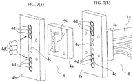
- FIGS. 3(a) and 3(b) are enlarged perspective views showing the translation control mechanism 4 in one of the roof-side support jigs 2 described above in a disassembled state and an assembled state, respectively.
- the translation control mechanism 4 includes a translation plate 4a as a movable member, which is fixed to the roof-side end portion 1a of the center pillar part 1, for example, by welding, and a support plate 4b as a fixed member, which is supported by a rotation restriction member 2a as a rectangular and thick-plate-shaped motion restriction member of the roof-side support jig 2.
- a compression protruding block 4c as a compression member protruding from the translation plate 4a toward the support plate 4b is slidably and in a rotation restriction state fit into a linear guide portion 4e, which is formed on the support plate 4b so as to extend in the vertical direction (movable direction of the translation plate) as a direction intersecting with the collision direction of the collision punch 6, and disposed with a plurality of, 3 pipes disposed each at the upper and lower sides in the example shown in FIG. 3 , metal cylindrical pipes 4d such as short steel pipes as energy-absorbing members.
- FIGS. 4(a), 4(b), 4(c), and 4(d) are descriptive diagrams showing the operation conditions of the translation control mechanism 4 in one of the roof-side support jigs 2 sequentially over time.
- FIG. 5 is a further enlarged descriptive diagram of FIG. 4(c) .
- the compression protruding block 4c in the linear guide portion 4e, first crushes to deform the upper three metal pipes 4d of the compression protruding block 4c and then crushes to deform the lower three metal pipes 4d of the compression protruding block 4c, and the resultant deformation resistance of the metal pipes 4d causes reaction force in the direction opposite to the translation direction to be applied to the translation plate 4a.
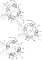
- FIGS. 6(a) and 6(b) are enlarged perspective views showing the rotation control mechanism 5 in the rocker-side support jigs 3 described above in a dissembled state and an assembled state, respectively.
- the rotation control mechanism 5 includes a fixed ring 5a as a fixed member, which is fixed to a rotation restriction member 3a as a rectangular and thick-plate-shaped motion restriction member of the rocker-side support jig 3, and a rotation ring 5b as a movable member, which is connected to the fixed ring 5a rotatably around an axial member 3d as a predetermined axis that is inserted into the rotation restriction member 3a to be supported and extends in a direction intersecting with the collision direction of the collision punch 6, and fixed to the rocker-side end portion 1b of the center pillar part 1, for example, by welding.
- 4 compression pins 5c as a compression member protruding from the fixed ring 5a toward the rotation ring 5b, are fit into 4 arcuate guide portions 5e, which are formed in the rotation ring 5b so as to extend in the circumferential direction (movable direction of the rotation ring) around the axial member 3d, and each disposed with a plurality of, 3 in the example shown in FIG. 3 , cylindrical metal pipe 5d, such as short steel pipes, as an energy absorption member.
- FIGS. 7(a), 7(b), and 7(c) are descriptive diagrams showing the operation conditions of the rotation control mechanism 5 in the rocker-side support jigs 3 sequentially over time.
- FIG. 8 is a further enlarged descriptive diagram of FIG. 7(c) .
- the 4 compression pins 5c each crush and deform the 3 metal pipes 5d in the corresponding arcuate guide portion 5e, and the resultant deformation resistance of the metal pipes 5d causes torque in the direction opposite to the rotation direction to be applied to the rotation ring 5b.
- FIGS. 9(a) and 9(b) are side views showing an initial shape of the center pillar part 1 before the part collision test and the shape thereof after the part collision test, respectively.
- the collision of the collision punch 6 with the center pillar part 1 applies a roof-side load to the roof-side end portion 1a and a rocker-side load on the rocker-side end portion 1b.
- the pair of right and left roof-side support jigs 2 and the pair of right and left rocker-side support jigs 3 are each provided with load cells 7, as shown in FIG. 1 .
- the roof-side support jigs 2 each include a rectangular frame-shaped main body 2b, the both side portions of which are open, and the main body 2b horizontally movably supports a slider 2c having a U-letter-like shape when viewed sideways while restricting the rotation of the slider 2c.
- the rotation restriction member 2a which supports the support plate 4b, is so fixed to a side surface of the slider 2c as to be unable to rotate, for example by welding, and so supported by the main body 2b of the roof-side support jig 2 as to be horizontally movable.
- the load cell 7 is disposed between the main body 2b and the slider 2c to measure a roof-side load H in the horizontal direction.
- Another load cell 7, although not shown, is disposed between the support plate 4b and the rotation restriction member 2a to measure a roof-side load V in the vertical direction.
- the rotation restriction member 3a, to which the fixed ring 5a is fixed, is so fixed to a side surface of the slider 3c as to be unable to rotate, for example by welding, and so supported by the main body 3b of the rocker-side support jig 3 as to be horizontally movable.
- the load cell 7 is disposed between the main body 3b and the slider 3c to measure the rocker-side load in the horizontal direction.
- the embodiment of a collision performance evaluation test method for an automobile body part simulating a side collision of another automobile with the center pillar portion of the automobile body of the automobile in question, performs a part collision test on the center pillar part 1 by using the embodiment of a collision performance evaluation test apparatus.
- the collision punch 6 is made collide with the central lower portion of the center pillar part 1, where the roof-side end portion 1a is supported by the roof-side support jigs 2 and the rocker-side end portion 1b is supported by the rocker-side support jigs 3, horizontally in a direction corresponding to the inward direction toward the interior of the automobile body (leftward in FIG. 1 ) at a test speed.
- the load cells 7 measure the roof-side load acting on the right and left roof-side support jigs 2 and the rocker-side load acting on the right and left rocker-side support jigs 3. Further, a change in the shape of the center pillar part 1 before and after the collision is measured, as shown in FIGS. 9(a) and 9(b) .
- the part collision test simulates the state of the collision that actually occurs, and the translation control mechanisms 4 in the roof-side support jigs 2 restrict the vertical movement as well as the rotation of the roof-side end portion 1a, because the roof-side end portion 1a is deformed to move in the vertical direction of the automobile body at the time of collision.
- the rotation control mechanisms 5 restrain the rotation of the rocker-side end portion 1b, because the rocker-side end portion 1b is deformed to twist around the front-back direction of the automobile body at the time of the collision.
- the restraint force to be produced at the roof-side end portion 1a is estimated in advance by a computer aided engineering (CAE) analysis, and the plate thickness of the steel pipes 4d and the number thereof are determined so that reaction force comparable to the estimated restraint force is produced. Further, the rotating torque to be produced at the rocker-side end portion 1b is estimated by the CAE, and the plate thickness of the steel pipes 4d and the number thereof are determined so that a rotating torque comparable to the estimated torque is produced.
- CAE computer aided engineering
- 6 metal pipes 4d each having a plate thickness of 1.2 mm, a diameter of 16 mm, and a length of 20 mm are disposed in each linear guide portion 4e, 12 metal pipes 4d in total in the right and left translation control mechanisms 4, and 3 metal pipes 5d are disposed in each arcuate guide portion 5e, 24 metal pipes 4d in total in the right and left rotation control mechanisms 5.
- the shape of a front-end portion of the collision punch 6 and the collision position of the punch with the center pillar part 1 are determined by simulating a cart used in the automobile body collision test.
- the collision punch 6 is made collide with the center pillar part 1 supported by the embodiment of a collision performance evaluation test apparatus for an automobile body part at a speed of 50 km/h by using a high-speed hydraulic-pressure servo deformation tester.
- S-letter-shaped deformation of the center pillar to be caused in actual automobile body collision is successfully reproduced, as shown in FIG. 9(b) .
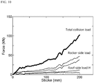
- FIG. 10 shows a graph showing the horizontal loads acting in the collision direction of the collision punch 6 and measured with the load cells 7 disposed in the right and left roof-side support jigs 2 and the right and left rocker-side support jigs 3 in the part collision test according to the example of the embodiment of a collision performance evaluation test method for an automobile body part, and further shows the total collision load that is the sum of the horizontal loads.
- the horizontal axis of FIG. 10 represents the stroke (mm) of the collision punch 6, and the vertical axis of FIG. 10 represents the magnitude (kN) of the horizontal load.
- the distribution of the load each produced at the roof-side end portion 1a and the rocker-side end portion 1b of the center pillar part 1 at the time of collision is also successfully measured, as shown in FIG. 10 .
- FIG. 11 shows a graph showing the loads acting in the downward direction, which intersects with the collision direction of the collision punch 6, and measured with the load cells 7 disposed in the right and left roof-side support jigs 2 in the part collision test according to the example of the embodiment of a collision performance evaluation test method for an automobile body part, and further shows the total collision load that is the sum of the downward loads.
- the horizontal axis of FIG. 11 represents the stroke (mm) of the collision punch 6, and the vertical axis of FIG. 11 represents the magnitude (kN) of the downward load.
- a downward load produced at the roof-side end portion 1a of the center pillar part 1 at the time of collision is also successfully measured, as shown in FIG. 11 , and the distribution of the load allows grasp of loads applied from the center pillar part 1 to other parts of the automobile body at the time of the collision deformation of the center pillar part 1.
- FIG. 12 is a perspective view showing another embodiment of a collision performance evaluation test apparatus for an automobile body part according to the present invention used in another embodiment of a collision performance evaluation test method for an automobile body part according to the present invention present invention
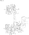
- FIG. 13 is a perspective view showing a center pillar part and support jigs that support the both ends thereof as the automobile body part in said another embodiment of a collision performance evaluation test apparatus for an automobile body part according to the present invention .
- the embodiment of a collision performance evaluation test apparatus for an automobile body part is intended to perform a test for evaluation of side collision performance of the center pillar part as the automobile body part of an automobile and includes: a pair of right and left roof-side support jigs 2, which support a roof-side end portion 1a as an upper end portion being one end portion of a center pillar part 1; a pair of right and left rocker-side support jigs 3, which support a rocker-side end portion 1b as a lower end portion being the other end portion of the center pillar part 1; rotation control mechanisms 5 as a motion control mechanism, which are provided in the rocker-side support jigs 3 supporting the rocker-side end portion 1b of the center pillar part 1 in the embodiment; and a collision punch 6, which collides with a central lower portion of the center pillar part 1, where the roof-side end portion 1a is supported by the roof-side support jigs 2 and the rocker-side end portion 1b is supported by the rocker-
- the rotation control mechanism 5 in the embodiment is the same as those described with reference to FIGS. 6 to 8 described above.
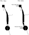
- FIGS. 14(a) and 14(b) are side views showing an initial shape of the center pillar part 1 before the part collision test and the shape thereof after the part collision test, respectively.
- the collision of the collision punch 6 with the center pillar part 1 applies a roof-side load to the roof-side end portion 1a and a rocker-side load on the rocker-side end portion 1b.
- the pair of right and left roof-side support jigs 2 and the pair of right and left rocker-side support jigs 3 are each provided with load cells 7, as shown in FIG. 12 .
- the rocker-side support jigs 3 each include a rectangular frame-shaped main body 3b, the both side portions of which are open, and the main body 3b horizontally movably supports a slider 3c having a U-letter-like shape when viewed sideways while restricting the rotation of the slider 3c.
- a rotation restriction member 3a to which the fixed ring 5a is fixed, is so fixed to a side surface of the slider 3c as to be unable to rotate, for example by welding, and so supported by the main body 3b of the rocker-side support jig 3 as to be horizontally movable.
- the load cell 7 is disposed between the main body 3b and the slider 3c.
- the roof-side support jigs 2 and the rocker-side support jigs 3 have roughly the same configuration except for the configuration in which the rocker-side support jigs 3 are each provided with the rotation control mechanism 5. Therefore, the roof-side support jigs 2 each include a rectangular frame-shaped main body 2b, and the main body 2b horizontally movably supports a slider 2c, which has a U-letter-like shape and to which a rectangular, thick-plate-shaped rotation restriction member 2a is fixed, while restricting the rotation of the slider 2c.
- the roof-side end portion 1a of the center pillar part 1 is directly fixed to the rotation restriction member 2a, for example by welding.
- the load cell 7 is disposed between the main body 2b and the slider 2c.
- the embodiment of a collision performance evaluation test method for an automobile body part simulating a side collision of another automobile with the center pillar portion of the automobile body of the automobile in question, performs a part collision test on the center pillar part 1 by using the embodiment of a collision performance evaluation test apparatus.
- the collision punch 6 is made collide with the central lower portion of the center pillar part 1, where the roof-side end portion 1a is supported by the roof-side support jigs 2 and the rocker-side end portion 1b is supported by the rocker-side support jigs 3, horizontally in a direction corresponding to the inward direction toward the interior of the automobile body (leftward in FIG. 12 ) at a test speed.
- the load cells 7 measure the roof-side load acting on the right and left roof-side support jigs 2 and the rocker-side load acting on the right and left rocker-side support jigs 3. Further, a change in the shape of the center pillar part 1 before and after the collision is measured, as shown in FIGS. 14(a) and 14(b) .
- the part collision test simulates the state of the collision that actually occurs, and the roof-side support jigs 2 are used to completely restrain the vertical and horizontal movements and the rotation of the roof-side end portion 1a.
- the rotation control mechanisms 5 restrain the rocker-side end portion 1b because the rocker-side end portion 1b is deformed to twist around the front-back direction of the automobile body at the time of the collision.
- the rotating torque to be produced at the rocker-side end portion 1b is estimated in advance by a Computer aided engineering (CAE) analysis, and the plate thickness of the steel pipes 5d and the number thereof are determined so that a rotating torque comparable to the estimated torque is produced.
- CAE Computer aided engineering
- the CAE analysis is used in advance to estimate torque produced at the rocker-side end portion 1b, and the plate thickness of the steel pipes 4d and the number thereof are determined so that torque comparable to the estimated torque is produced.
- 3 metal pipes 5d each having the plate thickness of 1.2 mm, the diameter of 16 mm, and the length of 20 mm are disposed in each arcuate guide portion 5e, 24 metal pipes 5d in total in the right and left rotation control mechanisms 5.
- the shape of a front-end portion of the collision punch 6 and the collision position of the punch with the center pillar part 1 are determined by simulating a cart used in the automobile body collision test.
- the collision punch 6 is made collide with the center pillar part 1 supported by the embodiment of a collision performance evaluation test apparatus for an automobile part at the speed of 50 km/h, by using the high-speed hydraulic-pressure servo deformation tester.
- S-letter-shaped deformation of the center pillar to be caused in an actual automobile body collision is successfully reproduced, as shown in FIG. 14(b) .
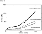
- FIG. 15 shows a graph showing collision loads acting in the collision direction of the collision punch 6 and measured with the load cells 7 in the part collision test according to the example of the embodiment of a collision resistance performance evaluation test method for an automobile body part.
- the horizontal axis of FIG. 15 represents the stroke (mm) of the collision punch 6, and the vertical axis of FIG. 15 represents the magnitude (kN) of the collision load.
- the distribution of each of the loads produced at the roof-side end portion 1a and the rocker-side end portion 1b of the center pillar part 1 at the time of the collision is also successfully measured, as shown in FIG. 15 , and the distributions of the loads allows grasp of loads applied from the center pillar part 1 to other parts of the automobile body at the time of the collision deformation of the center pillar part 1.
- the present invention has been described above based on the illustrated examples, but the present invention is not limited to the examples described above.
- the metal pipes 4d and 5d are used as the energy absorption member in the two embodiments described above.
- another component having another shape and material can be used.
- the roof-side support jigs 2, which support the roof-side end portion 1a of the center pillar part 1 as the one end portion of an automobile body part, are provided with the translation control mechanisms 4.
- the rocker-side support jigs 3, which support the rocker-side end portion 1b as the other end portion of the automobile body part may be provided with the translation control mechanisms 4.
- the rocker-side support jigs 3, which support the rocker-side end portion 1b of the center pillar part 1 as the other end portion of the automobile body part, are provided with the rotation control mechanisms 5.
- the roof-side support jigs 2, which support the roof-side end portion 1a as the one end portion of the automobile body part may be provided with the rotation control mechanisms 5.
- the compression protruding block 4c protrudes from the translation plate 4a, and the cylindrical metal pipes 4d are disposed in the support plate 4b.
- the compression protruding block 4c may protrude from the support plate 4b, and the cylindrical metal pipes 4d may be disposed in the translation plate 4a.
- the number of compression protruding blocks 4c is one in the embodiments, and the number can be changed as appropriate when required. In this case, the number of linear guide portions 4e can be changed as appropriate when required.
- the compression protruding block may be substituted with a compression pin.
- the compression pins 5c protrude from the fixed ring 5a, and the cylindrical metal pipes 5d are disposed in the rotation ring.
- the compression pins 5c may protrude from the rotation ring 5b, and the cylindrical metal pipes 5d may be disposed in the fixed ring 5a.
- the number of compression pins 5c is four in the embodiments described above, and the number can be changed as appropriate when required. In this case, the number of arcuate guide portions 5e can also be changed as appropriate when required.
- the collision performance evaluation test is performed on the center pillar part 1.
- the collision performance evaluation test may be performed on a front pillar part, a rear pillar part, and other automobile body parts.
- the motion control mechanism can apply reaction force in the opposite direction to an end portion of the automobile body part supported by a support jig provided with the motion control mechanism to control the motion of the end portion, whereby a collision performance evaluation test for a single automobile body part can be achieved while satisfactorily reproducing the part restraint state and load applied state at the time of an actual automobile body collision.
- the simple and sturdy structure in which an energy-absorbing member is disposed in the motion control mechanism in the support jig allows the test to be performed in a high-speed region of not less than 50 km/h.
- using an inexpensive member as the energy-absorbing member allows enhancement of the economic rationality of the test.
Landscapes
- Physics & Mathematics (AREA)
- General Physics & Mathematics (AREA)
- Engineering & Computer Science (AREA)
- Chemical & Material Sciences (AREA)
- Combustion & Propulsion (AREA)
- Transportation (AREA)
- Mechanical Engineering (AREA)
- Investigating Strength Of Materials By Application Of Mechanical Stress (AREA)
- Testing Of Devices, Machine Parts, Or Other Structures Thereof (AREA)
- Vibration Dampers (AREA)
Abstract
Description
- The present invention relates to a method and an apparatus for performing a collision performance evaluation test for an automobile body part.
- One of the performance requirements for an automobile body is collision performance, which is required to protect occupants while reducing damage to the automobile body at a collision. In the development and design stage of an automobile, a collision performance evaluation for the automobile body is essential, and has been estimated by a computer simulation. As means for confirming the achievement of the target collision performance, an auto manufacturer manufactures a prototype car for undergoing a collision test. If the target collision performance has not been achieved, it is necessary to manufacture another prototype car with measures and perform another collision test again, requiring significant development cost and time.
- To save the development cost and time, substituted for the collision performance evaluation test for the entire automobile body, a collision performance evaluation test for a single automobile body part (hereinafter also referred to as "part collision test") has been performed. To evaluate the collision performance of the entire automobile body by using the test for a single automobile body part, it is desired to develop a test method for performing a test that matches the actual deformation of the entire automobile body by controlling the part restraint and loading conditions.
- Among the automobile body parts, a center pillar part is responsible for an important role of protection of occupants, particularly at the time of side collision. The center pillar part is an I-letter-shaped part and coupled to other portions of the automobile body via an upper roof section and a lower rocker section (also called side sill section). In the event of a collision with another automobile from the side direction, the center pillar part functions to minimize the intrusion of the collided automobile into the interior of the automobile while deforming into a S-letter-shaped form. In the collision, the lower rocker section restrains the deformation of the central portion of the center pillar part while deforming so as to be twisted. In the part collision test, it is necessary to reproduce such deformation and loading conditions of the automobile body part to be tested and the surrounding automobile body.
- For example,
Patent Literature 1 proposes a collision performance evaluation test method for an automobile body part and a part collision test apparatus used in the method. The evaluation test method and the test apparatus simulate deformation resistance on the automobile body side by attaching a restraint jig that is the combination of a flywheel and a one-way clutch to each supporting point of the automobile body part. -
Patent Literature 2 proposes a part support jig capable of applying torque in a part collision test. The part support jig can, by combining a rack and pinion gear and a spring, restrain deformation of an automobile body part with a spring force, and adjust the restraint state of the automobile body part by varying the strength of the spring. -
- Patent Literature 1:
Japanese Patent No. 4902027 - Patent Literature 2:
JP-A- 2016-061725 - A part collision test is desirably performed at varying speeds from several kilometers per hour to about one hundred kilometers per hour. A jig used in the part collision test is therefore required to have a configuration and strength that can withstand the varying speeds. Since the part collision test needs to be performed multiple times under a variety of conditions, economic rationality is also considered to be important.
- The method proposed in
Patent Literature 1, however, uses the inertial force of the flywheel to apply restraint force to the automobile body part, and therefore it is difficult to perform the test in a low-speed region under a desired condition where the inertial force is produced. In the test in a high-speed region, on the other hand, it is necessary to adjust the mass of the flywheel in accordance with the speed change, and therefore an increase in the test cost is concerned. - The method proposed in
Patent Literature 2 uses a rack-and-pinion and spring-type restraint mechanism to obtain a restrain force for an automobile body part, and therefore the mechanism is complex. Thus, the method has such a problem that, in a test in a high-speed region exceeding 50 km/h, an impacting load does not allow the mechanism to operate or even breaks the test apparatus itself in the worst case. - The present invention aims to provide a collision performance evaluation test method and a collision performance evaluation test apparatus for an automobile body part that advantageously solve the above-mentioned problems of test speed limitations and economic rationality.
- A collision performance evaluation test method for an automobile body part according to the present invention that achieves the object includes
- supporting one end portion and the other end portion of the automobile body part with a support jig, respectively, and
- disposing a motion control mechanism on at least one of the support jig that supports one end portion of the automobile body part and the support jig that supports the other end portion of the automobile body part, in which:
- the motion control mechanism has a fixed member that is fixed to a motion restriction member of the support jig and a movable member that is so connected to the fixed member as to be movable in a predetermined direction with respect to a collision direction of a collision punch and also fixed to the one end portion or the other end portion of the automobile body part;
- a compression member protruding from one of the fixed member and the movable member toward the other is fitted in a motion-restriction state into a guide portion, which is formed on the other of the fixed member and the movable member so as to extend in the movable direction of the movable member and is disposed with an energy-absorbing member therein, and deforms the energy-absorbing member by motion of the movable member with respect to the fixed member in the predetermined direction to apply reaction force to the movable member in a direction opposite to the direction of the motion;
- the collision punch is made collide with the automobile body part in the collision direction at a test speed; and
- the reaction force in the opposite direction is applied via the motion control mechanism to an end portion, which is supported by the support jig provided with the motion control mechanism out of the one end portion and the other end portion of the automobile body part, to control the motion of the end portion.
- A collision performance evaluation test apparatus for an automobile body part according to the present invention that achieves the object described above is an apparatus that performs a collision performance evaluation test for an automobile body part and includes
- support jigs that support one end and the other end of the automobile body part respectively, and
- a collision punch that collides with the automobile body part with the one end portion and the other end portion each supported by the support jigs, at a test speed, and
- a motion control mechanism provided in at least one of the support jig that supports one end portion of the automobile body part and the support jig that supports the other end portion of the automobile body part, in which
- the motion control mechanism has a fixed member that is fixed to a motion restriction member of the support jig and a movable member that is so connected to the fixed member as to be movable in a predetermined direction with respect to a collision direction of the collision punch and also fixed to the one end portion or the other end portion of the automobile body part;
- a compression member protruding from one of the fixed member and the movable member toward the other is fitted in a motion restriction state into a guide portion, which is formed on the other of the fixed member and the movable member so as to extend in the movable direction of the movable member and is disposed with an energy-absorbing member therein, and deforms the energy-absorbing member by motion of the movable member with respect to the fixed member in the predetermined direction to apply reaction force to the movable member in a direction opposite to the direction of the motion.
- The collision performance evaluation test method for an automobile body part according to the present invention performs a collision performance evaluation test for an automobile body part and includes
supporting one end portion and the other end portion of the automobile body part with a support jig, respectively,
and disposing a motion control mechanism on at least one of the support jig that supports one end portion of the automobile body part and the support jig that supports the other end portion of the automobile body part, in which: - the motion control mechanism has a fixed member that is fixed to a motion restriction member of the support jig and a movable member that is so connected to the fixed member as to be movable in a predetermined direction with respect to a collision direction of the collision punch and also fixed to the one end portion or the other end portion of the automobile body part;
- a compression member protruding from one of the fixed member and the movable member toward the other is fitted in a motion-restriction state into a guide portion, which is formed on the other of the fixed member and the movable member so as to extend in the movable direction of the movable member and is disposed with an energy-absorbing member therein, and deforms the energy-absorbing member by motion of the movable member with respect to the fixed member in the predetermined direction to apply reaction force to the movable member in a direction opposite to the direction of the motion;
- the collision punch is made collide with the automobile body part in the collision direction at a test speed; and the reaction force in the opposite direction is applied via the motion control mechanism to an end portion, which is supported by the support jig provided with the motion control mechanism out of the one end portion and the other end portion of the automobile body part, to control the motion of the end portion.
- Therefore, according to the collision performance evaluation test method for an automobile body part of the present invention, as the collision punch is made collide with the automobile body part at a test speed, the motion control mechanism applies the reaction force in the opposite direction to the end portion of the automobile body part that is supported by the support jig provided with the motion control mechanism to control the motion of the end portion, whereby a collision performance evaluation test for a single automobile body part can be achieved while satisfactorily reproducing the part restraint state and load applied state at the time of an actual automobile body collision. Further, the simple and sturdy structure that arranges the energy-absorbing member in the motion control mechanism of the support jig allows a test to be performed in a high-speed region, at a speed of not less than 50 km/h. Moreover, using an inexpensive member as the energy-absorbing member can enhance the economic rationality of the test.
- Moreover, the collision performance evaluation test method for an automobile body part according to the present invention has such a configuration that:
- the motion control mechanism is at least one selected from a translation control mechanism and a rotation control mechanism;
- the translation control mechanism includes
- a support plate that is supported by a rotation restriction member in the support jig and
- a translation plate that is translatably connected to the support plate in a predetermined direction intersecting with a collision direction of the collision punch and also is fixed to the one end portion or the other end portion of the automobile body part;
- a compression protruding block protruding from one of the support plate and the translation plate toward the other is fitted, in a rotation restriction state, into a linear guide portion, which is formed in the other one of the support plate and the translation plate so as to extend in a translatable direction of the translation plate and is disposed with an energy-absorbing member therein, and deforms the energy-absorbing member by translation of the translation plate in the predetermined direction with respect to the support plate to apply reaction force in a direction opposite to a translation direction to the translation plate;
- the rotation control mechanism includes
- a fixed ring that is fixed to a rotation restriction member in the support jig and
- a rotation ring that is connected to the fixed ring so as to be rotatable around a predetermined axis extending in a predetermined direction that intersects with the collision direction of the collision punch and fixed to the one end portion or the other end portion of the automobile body part; and
- a compression pin protruding from one of the fixed ring and the rotation ring toward the other is fitted into an arcuate guide portion, which is formed in the other one of the fixed ring and the rotation ring so as to extend in a circumferential direction centering on the predetermined axis and is disposed with an energy-absorbing member therein, and deforms the energy-absorbing member by rotation of the rotation ring around the predetermined axis with respect to the fixed ring to apply torque in a direction opposite to a direction of the rotating direction to the rotation ring. By applying the collision performance evaluation test method for an automobile body part according to the invention having the above configuration, a collision performance evaluation test for a single automobile body part can be achieved while further satisfactorily reproducing the part restraint state and load applied state at the time of an actual automobile body collision.
- A collision performance evaluation test apparatus for an automobile body part according to the present invention includes
- support jigs that support one end and the other end of the automobile body part respectively, and
- a collision punch that collides with the automobile body part with the one end portion and the other end portion supported by the support jigs, at a test speed, and
- a motion control mechanism provided in at least one of the support jig that supports one end portion of the automobile body part and the support jig that supports the other end portion of the automobile body part, in which
- the motion control mechanism has a fixed member that is fixed to a motion restriction member of the support jig and a movable member that is so connected to the fixed member as to be movable in a predetermined direction with respect to a collision direction of the collision punch and also fixed to the one end portion or the other end portion of the automobile body part;
- a compression member protruding from one of the fixed member and the movable member toward the other is fitted in a motion restriction state into a guide portion, which is formed on the other of the fixed member and the movable member so as to extend in the movable direction of the movable member and is disposed with an energy-absorbing member therein, and deforms the energy-absorbing member by motion of the movable member with respect to the fixed member in the predetermined direction to apply reaction force to the movable member in a direction opposite to the direction of the motion.
- According to the collision performance evaluation test apparatus for an automobile body part of the present invention, as the collision punch is made collide with the automobile body part at a test speed, the motion control mechanism applies the reaction force in the opposite direction to the end portion of the automobile body part that is supported by the support jig provided with the motion control mechanism to control the motion of the end portion, whereby a collision performance evaluation test for a single automobile body part can be achieved while satisfactorily reproducing the part restraint state and load applied state at the time of an actual automobile body collision. Further, the simple and sturdy structure that arranges the energy-absorbing member in the motion control mechanism of the support jig allows a test to be performed in a high-speed region, at a speed of not less than 50 km/h. Moreover, using an inexpensive member as the energy-absorbing member can enhance the economic rationality of the test.
- Moreover, the collision performance evaluation test apparatus for an automobile body part according to the present invention has such a configuration that:
- the motion control mechanism is at least one selected from a translation control mechanism and a rotation control mechanism;
- the translation control mechanism includes
- a support plate that is supported by a rotation restriction member in the support jig and
- a translation plate that is translatably connected to the support plate in a predetermined direction intersecting with a collision direction of the collision punch and also is fixed to the one end portion or the other end portion of the automobile body part;
- a compression protruding block protruding from one of the support plate and the translation plate toward the other is fitted, in a rotation restriction state, into a linear guide portion, which is formed in the other one of the support plate and the translation plate so as to extend in a translatable direction of the translation plate and is disposed with an energy-absorbing member therein, and deforms the energy-absorbing member by translation of the translation plate in the predetermined direction with respect to the support plate to apply reaction force in a direction opposite to a translation direction to the translation plate;
- the rotation control mechanism includes
- a fixed ring that is fixed to a rotation restriction member in the support jig and
- a rotation ring that is connected to the fixed ring so as to be rotatable around a predetermined axis extending in a direction that intersects with the collision direction of the collision punch and fixed to the one end portion or the other end portion of the automobile body part; and
- a compression pin protruding from one of the fixed ring and the rotation ring toward the other is fitted into an arcuate guide portion, which is formed in the other one of the fixed ring and the rotation ring so as to extend in a circumferential direction centering on the predetermined axis and is disposed with an energy-absorbing member therein, and deforms the energy-absorbing member by rotation of the rotation ring around the predetermined axis with respect to the fixed ring to apply torque in a direction opposite to a direction of the rotating direction to the rotation ring. Alternatively, the collision performance evaluation test apparatus for an automobile body part according to the present invention includes the translation control mechanism disposed in one of the support jig that supports the one end portion of the automobile body part and the support jig that supports the other end portion of the automobile body part and the rotation control mechanism provided in the other of the support jig that supports the one end portion of the automobile body part and the support jig that supports the other end portion of the automobile body part. By applying the thus configured collision performance evaluation test method for an automobile body part according to the invention, a collision performance evaluation test for a single automobile body part can be achieved while further satisfactorily reproducing the part restraint state and load applied state at the time of an actual automobile body collision.
- In the collision performance evaluation test method and apparatus for an automobile body part according to the present invention, the automobile body part is preferably a center pillar part. The reason for this is that the center pillar part is largely affected by the part restraint state and load applied state in the part collision test. Further, it is preferable that the motion control mechanism preferably reproduces a deformation state of the automobile body part that occurs in actual automobile body collision, because it can enhance the accuracy of the collision performance evaluation of the automobile body part.
- Further, in the collision performance evaluation test method and apparatus for an automobile body part according to the present invention, it is preferable that the support jig that supports the one end portion of the automobile body part and the support jig that supports the other end portion of the automobile body part each include a load cell for load measurement, and that the load cells each measure a distribution of a deformation load caused in the collision deformation of the collision punch with the automobile body part. The reason for this is that the distribution of the deformation load allows grasp of loads applied from the automobile body part to other portions of the automobile body at the time of the collision deformation of the automobile body part. The energy-absorbing member is preferably a commercially available cylindrical metal pipe, because the commercially available cylindrical metal pipe is available at low cost and has stable energy absorption capability.
-
-
FIG. 1 is a perspective view showing an embodiment of a collision performance evaluation test apparatus for an automobile body part according to the present invention used in an embodiment of a collision performance evaluation test method for an automobile body part according to the present invention. -
FIG. 2 is a perspective view showing a center pillar part as an automobile body part and support jigs that support both ends thereof, in the embodiment of a collision performance evaluation test apparatus for an automobile body part. -
FIGS. 3(a) and 3(b) are enlarged perspective views each showing a translation control mechanism in a roof-side support jig that supports a roof section being an upper end portion of the center pillar part, in an exploded state and an assembled state, respectively. -
FIGS. 4(a), 4(b), 4(c), and 4(d) are descriptive diagrams showing the operation conditions of the translation control mechanism in the roof-side support jigs sequentially overtime. -
FIG. 5 is a further enlarged descriptive diagram ofFIG. 4(c) . -
FIGS. 6(a) and 6(b) are enlarged perspective views each showing a rotation control mechanism in a rocker-side support jig that supports a rocker section being a lower end portion of the center pillar part, in a disassembled state and an assembled state, respectively. -
FIGS.7(a), 7(b), and 7(c) are descriptive diagrams showing the operation conditions of the rotation control mechanism in the rocker-side support jig sequentially overtime. -
FIG. 8 is a further enlarged descriptive diagram ofFIG. 4(c) . -
FIGS. 9(a) and 9(b) are side views showing an initial shape of the center pillar part before a part collision test and a shape thereof after the part collision test, respectively, in the embodiment. -
FIG. 10 shows a graph showing horizontal loads acting in the collision direction of a collision punch measured in a part collision test by the embodiment of a collision performance evaluation test method for an automobile body part. -
FIG. 11 shows a graph showing loads acting in the downward direction, which intersects with the collision direction of the collision punch measured in the part collision test in the embodiment of a collision performance evaluation test method for an automobile body part. -
FIG. 12 is a perspective view showing another embodiment of a collision performance evaluation test apparatus for an automobile body part according to the present invention used by another embodiment of a collision performance evaluation test method for an automobile body part according to the present invention. -
FIG. 13 is a perspective view showing a center pillar part as an automobile body part and support jigs that support both ends thereof, in said another embodiment of a collision performance evaluation test apparatus for an automobile body part. -
FIGS. 14(a) and 14(b) are side views showing an initial shape of the center pillar part before a part collision test and the shape thereof after the part collision test, respectively, in said another embodiment. -
FIG. 15 shows a graph illustrating collision loads acting in a collision direction of a collision punch and measured in the part collision test according to said embodiment of a collision performance evaluation test method for an automobile body part - An embodiment of the present invention will be described below in detail with reference to the drawings.
FIG. 1 is a perspective view showing an embodiment of a collision performance evaluation test apparatus for an automobile body part according to the present invention used in an embodiment of a collision performance evaluation test method for an automobile body part according to the present invention, andFIG. 2 is a perspective view showing a center pillar part as an automobile body part and support jigs that support both ends thereof in the embodiment of a collision performance evaluation test apparatus for an automobile body part. - The embodiment of a collision performance evaluation test apparatus for an automobile body part is intended to perform an evaluation test of side collision performance of a center pillar part as an automobile body part, and, as shown in
FIG. 1 , includes: a pair of right and left roof-side support jigs 2, which support a roof-side end portion 1a as an upper end portion being one end portion of a center pillar part 1; a pair of right and left rocker-side support jigs 3, which support a rocker-side end portion 1b as a lower end portion being the other end portion of the center pillar part 1; a translation control mechanism 4 as a motion control mechanism, which is provided in each roof-side support jig 2 that supports the roof-side end portion 1a of the center pillar part 1 in the embodiment; rotation control mechanism 5 as a motion control mechanism, which is provided in each rocker-side support jig 3 that supports the rocker-side end portion 1b of the center pillar part 1 in the embodiment; and a collision punch 6, which collides with a central lower portion of the center pillar part 1, where the roof-side end portion 1a is supported by the roof-side support jigs 2 and the rocker-side end portion 1b is supported by the rocker-side support jigs 3, horizontally in a direction corresponding to the direction toward the interior of the automobile body at a test speed. -
FIGS. 3(a) and 3(b) are enlarged perspective views showing thetranslation control mechanism 4 in one of the roof-side support jigs 2 described above in a disassembled state and an assembled state, respectively. Thetranslation control mechanism 4 includes atranslation plate 4a as a movable member, which is fixed to the roof-side end portion 1a of thecenter pillar part 1, for example, by welding, and asupport plate 4b as a fixed member, which is supported by arotation restriction member 2a as a rectangular and thick-plate-shaped motion restriction member of the roof-side support jig 2. In the embodiment, acompression protruding block 4c as a compression member protruding from thetranslation plate 4a toward thesupport plate 4b is slidably and in a rotation restriction state fit into alinear guide portion 4e, which is formed on thesupport plate 4b so as to extend in the vertical direction (movable direction of the translation plate) as a direction intersecting with the collision direction of thecollision punch 6, and disposed with a plurality of, 3 pipes disposed each at the upper and lower sides in the example shown inFIG. 3 , metalcylindrical pipes 4d such as short steel pipes as energy-absorbing members. -
FIGS. 4(a), 4(b), 4(c), and 4(d) are descriptive diagrams showing the operation conditions of thetranslation control mechanism 4 in one of the roof-side support jigs 2 sequentially over time.FIG. 5 is a further enlarged descriptive diagram ofFIG. 4(c) . When thecollision punch 6 collides with acenter pillar part 1, where the roof-side end portion 1a is supported by the roof-side support jigs 2 and the rocker-side end portion 1b is supported by the rocker-side support jigs 3, horizontally in a direction corresponding to the direction toward the interior of the automobile body at a test speed, thetranslation plate 4a translates in the vertical direction with respect to thesupport plate 4b, and, as shown inFIG. 4 andFIG. 5 , thecompression protruding block 4c, in thelinear guide portion 4e, first crushes to deform the upper threemetal pipes 4d of thecompression protruding block 4c and then crushes to deform the lower threemetal pipes 4d of thecompression protruding block 4c, and the resultant deformation resistance of themetal pipes 4d causes reaction force in the direction opposite to the translation direction to be applied to thetranslation plate 4a. -
FIGS. 6(a) and 6(b) are enlarged perspective views showing therotation control mechanism 5 in the rocker-side support jigs 3 described above in a dissembled state and an assembled state, respectively. Therotation control mechanism 5 includes a fixedring 5a as a fixed member, which is fixed to arotation restriction member 3a as a rectangular and thick-plate-shaped motion restriction member of the rocker-side support jig 3, and arotation ring 5b as a movable member, which is connected to the fixedring 5a rotatably around anaxial member 3d as a predetermined axis that is inserted into therotation restriction member 3a to be supported and extends in a direction intersecting with the collision direction of thecollision punch 6, and fixed to the rocker-side end portion 1b of thecenter pillar part 1, for example, by welding. In the embodiment, 4 compression pins 5c as a compression member protruding from the fixedring 5a toward therotation ring 5b, are fit into 4arcuate guide portions 5e, which are formed in therotation ring 5b so as to extend in the circumferential direction (movable direction of the rotation ring) around theaxial member 3d, and each disposed with a plurality of, 3 in the example shown inFIG. 3 ,cylindrical metal pipe 5d, such as short steel pipes, as an energy absorption member. -
FIGS. 7(a), 7(b), and 7(c) are descriptive diagrams showing the operation conditions of therotation control mechanism 5 in the rocker-side support jigs 3 sequentially over time.FIG. 8 is a further enlarged descriptive diagram ofFIG. 7(c) . When thecollision punch 6 collides with thecenter pillar part 1, where the roof-side end portion 1a is supported by the roof-side support jigs 2 and the rocker-side end portion 1b is supported by the rocker-side support jigs 3, horizontally in a direction corresponding to the direction toward the interior of the automobile body at a test speed, therotation ring 5b rotates around theaxial member 3d with respect to the fixedring 5a, and, as shown inFIGS. 4 and5 , the 4 compression pins 5c each crush and deform the 3metal pipes 5d in the correspondingarcuate guide portion 5e, and the resultant deformation resistance of themetal pipes 5d causes torque in the direction opposite to the rotation direction to be applied to therotation ring 5b. -
FIGS. 9(a) and 9(b) are side views showing an initial shape of thecenter pillar part 1 before the part collision test and the shape thereof after the part collision test, respectively. In the part collision test, the collision of thecollision punch 6 with thecenter pillar part 1 applies a roof-side load to the roof-side end portion 1a and a rocker-side load on the rocker-side end portion 1b. To measure the loads, the pair of right and left roof-side support jigs 2 and the pair of right and left rocker-side support jigs 3 are each provided withload cells 7, as shown inFIG. 1 . - The roof-side support jigs 2 each include a rectangular frame-shaped
main body 2b, the both side portions of which are open, and themain body 2b horizontally movably supports aslider 2c having a U-letter-like shape when viewed sideways while restricting the rotation of theslider 2c. Therotation restriction member 2a, which supports thesupport plate 4b, is so fixed to a side surface of theslider 2c as to be unable to rotate, for example by welding, and so supported by themain body 2b of the roof-side support jig 2 as to be horizontally movable. Theload cell 7 is disposed between themain body 2b and theslider 2c to measure a roof-side load H in the horizontal direction. Anotherload cell 7, although not shown, is disposed between thesupport plate 4b and therotation restriction member 2a to measure a roof-side load V in the vertical direction. - The rocker-side support jigs 3, as similarly to the roof-side support jigs 2, each include a rectangular frame-shaped
main body 3b, the both side portions of which are open, and themain body 3b horizontally movably supports aslider 3c having a U-letter-like shape when viewed sideways while restricting the rotation of theslider 3c. Therotation restriction member 3a, to which the fixedring 5a is fixed, is so fixed to a side surface of theslider 3c as to be unable to rotate, for example by welding, and so supported by themain body 3b of the rocker-side support jig 3 as to be horizontally movable. Theload cell 7 is disposed between themain body 3b and theslider 3c to measure the rocker-side load in the horizontal direction. - The embodiment of a collision performance evaluation test method for an automobile body part, simulating a side collision of another automobile with the center pillar portion of the automobile body of the automobile in question, performs a part collision test on the
center pillar part 1 by using the embodiment of a collision performance evaluation test apparatus. In the test, thecollision punch 6 is made collide with the central lower portion of thecenter pillar part 1, where the roof-side end portion 1a is supported by the roof-side support jigs 2 and the rocker-side end portion 1b is supported by the rocker-side support jigs 3, horizontally in a direction corresponding to the inward direction toward the interior of the automobile body (leftward inFIG. 1 ) at a test speed. To measure the distribution of the loads produced at the time of the collision, theload cells 7 measure the roof-side load acting on the right and left roof-side support jigs 2 and the rocker-side load acting on the right and left rocker-side support jigs 3. Further, a change in the shape of thecenter pillar part 1 before and after the collision is measured, as shown inFIGS. 9(a) and 9(b) . - The part collision test simulates the state of the collision that actually occurs, and the
translation control mechanisms 4 in the roof-side support jigs 2 restrict the vertical movement as well as the rotation of the roof-side end portion 1a, because the roof-side end portion 1a is deformed to move in the vertical direction of the automobile body at the time of collision. On the other hand, therotation control mechanisms 5 restrain the rotation of the rocker-side end portion 1b, because the rocker-side end portion 1b is deformed to twist around the front-back direction of the automobile body at the time of the collision. The restraint force to be produced at the roof-side end portion 1a is estimated in advance by a computer aided engineering (CAE) analysis, and the plate thickness of thesteel pipes 4d and the number thereof are determined so that reaction force comparable to the estimated restraint force is produced. Further, the rotating torque to be produced at the rocker-side end portion 1b is estimated by the CAE, and the plate thickness of thesteel pipes 4d and the number thereof are determined so that a rotating torque comparable to the estimated torque is produced. - For example, in an example of the embodiment of a collision performance evaluation test method for an automobile body part, 6
metal pipes 4d each having a plate thickness of 1.2 mm, a diameter of 16 mm, and a length of 20 mm are disposed in eachlinear guide portion 4e, 12metal pipes 4d in total in the right and lefttranslation control mechanisms metal pipes 5d are disposed in eacharcuate guide portion 5e, 24metal pipes 4d in total in the right and leftrotation control mechanisms 5. The shape of a front-end portion of thecollision punch 6 and the collision position of the punch with thecenter pillar part 1 are determined by simulating a cart used in the automobile body collision test. - In the part collision test in the example, the
collision punch 6 is made collide with thecenter pillar part 1 supported by the embodiment of a collision performance evaluation test apparatus for an automobile body part at a speed of 50 km/h by using a high-speed hydraulic-pressure servo deformation tester. As a result, S-letter-shaped deformation of the center pillar to be caused in actual automobile body collision is successfully reproduced, as shown inFIG. 9(b) . -
FIG. 10 shows a graph showing the horizontal loads acting in the collision direction of thecollision punch 6 and measured with theload cells 7 disposed in the right and left roof-side support jigs 2 and the right and left rocker-side support jigs 3 in the part collision test according to the example of the embodiment of a collision performance evaluation test method for an automobile body part, and further shows the total collision load that is the sum of the horizontal loads. The horizontal axis ofFIG. 10 represents the stroke (mm) of thecollision punch 6, and the vertical axis ofFIG. 10 represents the magnitude (kN) of the horizontal load. The distribution of the load each produced at the roof-side end portion 1a and the rocker-side end portion 1b of thecenter pillar part 1 at the time of collision is also successfully measured, as shown inFIG. 10 . -
FIG. 11 shows a graph showing the loads acting in the downward direction, which intersects with the collision direction of thecollision punch 6, and measured with theload cells 7 disposed in the right and left roof-side support jigs 2 in the part collision test according to the example of the embodiment of a collision performance evaluation test method for an automobile body part, and further shows the total collision load that is the sum of the downward loads. The horizontal axis ofFIG. 11 represents the stroke (mm) of thecollision punch 6, and the vertical axis ofFIG. 11 represents the magnitude (kN) of the downward load. A downward load produced at the roof-side end portion 1a of thecenter pillar part 1 at the time of collision is also successfully measured, as shown inFIG. 11 , and the distribution of the load allows grasp of loads applied from thecenter pillar part 1 to other parts of the automobile body at the time of the collision deformation of thecenter pillar part 1. -
FIG. 12 is a perspective view showing another embodiment of a collision performance evaluation test apparatus for an automobile body part according to the present invention used in another embodiment of a collision performance evaluation test method for an automobile body part according to the present invention present invention, andFIG. 13 is a perspective view showing a center pillar part and support jigs that support the both ends thereof as the automobile body part in said another embodiment of a collision performance evaluation test apparatus for an automobile body part according to the present invention . - The embodiment of a collision performance evaluation test apparatus for an automobile body part according to the present invention is intended to perform a test for evaluation of side collision performance of the center pillar part as the automobile body part of an automobile and includes: a pair of right and left roof-side support jigs 2, which support a roof-side end portion 1a as an upper end portion being one end portion of a
center pillar part 1; a pair of right and left rocker-side support jigs 3, which support a rocker-side end portion 1b as a lower end portion being the other end portion of thecenter pillar part 1;rotation control mechanisms 5 as a motion control mechanism, which are provided in the rocker-side support jigs 3 supporting the rocker-side end portion 1b of thecenter pillar part 1 in the embodiment; and acollision punch 6, which collides with a central lower portion of thecenter pillar part 1, where the roof-side end portion 1a is supported by the roof-side support jigs 2 and the rocker-side end portion 1b is supported by the rocker-side support jigs 3, horizontally in a direction corresponding to the inward direction toward the interior of the automobile body at a test speed, as shown inFIG. 12 . - The
rotation control mechanism 5 in the embodiment is the same as those described with reference toFIGS. 6 to 8 described above. -
FIGS. 14(a) and 14(b) are side views showing an initial shape of thecenter pillar part 1 before the part collision test and the shape thereof after the part collision test, respectively. In the part collision test, the collision of thecollision punch 6 with thecenter pillar part 1 applies a roof-side load to the roof-side end portion 1a and a rocker-side load on the rocker-side end portion 1b. To measure the loads, the pair of right and left roof-side support jigs 2 and the pair of right and left rocker-side support jigs 3 are each provided withload cells 7, as shown inFIG. 12 . - The rocker-side support jigs 3 each include a rectangular frame-shaped
main body 3b, the both side portions of which are open, and themain body 3b horizontally movably supports aslider 3c having a U-letter-like shape when viewed sideways while restricting the rotation of theslider 3c. Arotation restriction member 3a, to which the fixedring 5a is fixed, is so fixed to a side surface of theslider 3c as to be unable to rotate, for example by welding, and so supported by themain body 3b of the rocker-side support jig 3 as to be horizontally movable. Theload cell 7 is disposed between themain body 3b and theslider 3c. - The roof-side support jigs 2 and the rocker-side support jigs 3 have roughly the same configuration except for the configuration in which the rocker-side support jigs 3 are each provided with the
rotation control mechanism 5. Therefore, the roof-side support jigs 2 each include a rectangular frame-shapedmain body 2b, and themain body 2b horizontally movably supports aslider 2c, which has a U-letter-like shape and to which a rectangular, thick-plate-shapedrotation restriction member 2a is fixed, while restricting the rotation of theslider 2c. The roof-side end portion 1a of thecenter pillar part 1 is directly fixed to therotation restriction member 2a, for example by welding. Theload cell 7 is disposed between themain body 2b and theslider 2c. - The embodiment of a collision performance evaluation test method for an automobile body part, simulating a side collision of another automobile with the center pillar portion of the automobile body of the automobile in question, performs a part collision test on the
center pillar part 1 by using the embodiment of a collision performance evaluation test apparatus. In the test, thecollision punch 6 is made collide with the central lower portion of thecenter pillar part 1, where the roof-side end portion 1a is supported by the roof-side support jigs 2 and the rocker-side end portion 1b is supported by the rocker-side support jigs 3, horizontally in a direction corresponding to the inward direction toward the interior of the automobile body (leftward inFIG. 12 ) at a test speed. To measure the distribution of the loads produced at the time of the collision, theload cells 7 measure the roof-side load acting on the right and left roof-side support jigs 2 and the rocker-side load acting on the right and left rocker-side support jigs 3. Further, a change in the shape of thecenter pillar part 1 before and after the collision is measured, as shown inFIGS. 14(a) and 14(b) . - The part collision test simulates the state of the collision that actually occurs, and the roof-side support jigs 2 are used to completely restrain the vertical and horizontal movements and the rotation of the roof-side end portion 1a. On the other hand, the
rotation control mechanisms 5 restrain the rocker-side end portion 1b because the rocker-side end portion 1b is deformed to twist around the front-back direction of the automobile body at the time of the collision. The rotating torque to be produced at the rocker-side end portion 1b is estimated in advance by a Computer aided engineering (CAE) analysis, and the plate thickness of thesteel pipes 5d and the number thereof are determined so that a rotating torque comparable to the estimated torque is produced. Further, the CAE analysis is used in advance to estimate torque produced at the rocker-side end portion 1b, and the plate thickness of thesteel pipes 4d and the number thereof are determined so that torque comparable to the estimated torque is produced. For example, in an example of the embodiment of a collision performance evaluation test method for an automobile body part, 3metal pipes 5d each having the plate thickness of 1.2 mm, the diameter of 16 mm, and the length of 20 mm are disposed in eacharcuate guide portion 5e, 24metal pipes 5d in total in the right and leftrotation control mechanisms 5. The shape of a front-end portion of thecollision punch 6 and the collision position of the punch with thecenter pillar part 1 are determined by simulating a cart used in the automobile body collision test. - In the part collision test in the example, the
collision punch 6 is made collide with thecenter pillar part 1 supported by the embodiment of a collision performance evaluation test apparatus for an automobile part at the speed of 50 km/h, by using the high-speed hydraulic-pressure servo deformation tester. As a result, S-letter-shaped deformation of the center pillar to be caused in an actual automobile body collision is successfully reproduced, as shown inFIG. 14(b) . -
FIG. 15 shows a graph showing collision loads acting in the collision direction of thecollision punch 6 and measured with theload cells 7 in the part collision test according to the example of the embodiment of a collision resistance performance evaluation test method for an automobile body part. The horizontal axis ofFIG. 15 represents the stroke (mm) of thecollision punch 6, and the vertical axis ofFIG. 15 represents the magnitude (kN) of the collision load. As a result, the distribution of each of the loads produced at the roof-side end portion 1a and the rocker-side end portion 1b of thecenter pillar part 1 at the time of the collision is also successfully measured, as shown inFIG. 15 , and the distributions of the loads allows grasp of loads applied from thecenter pillar part 1 to other parts of the automobile body at the time of the collision deformation of thecenter pillar part 1. - The present invention has been described above based on the illustrated examples, but the present invention is not limited to the examples described above. For example, the
metal pipes metal pipes - In one of the embodiments described above, the roof-side support jigs 2, which support the roof-side end portion 1a of the
center pillar part 1 as the one end portion of an automobile body part, are provided with thetranslation control mechanisms 4. In place of or in addition to such a configuration, the rocker-side support jigs 3, which support the rocker-side end portion 1b as the other end portion of the automobile body part, may be provided with thetranslation control mechanisms 4. - In the two embodiments, the rocker-side support jigs 3, which support the rocker-
side end portion 1b of thecenter pillar part 1 as the other end portion of the automobile body part, are provided with therotation control mechanisms 5. In place of or in addition to such a configuration, the roof-side support jigs 2, which support the roof-side end portion 1a as the one end portion of the automobile body part, may be provided with therotation control mechanisms 5. - Further, in one of the embodiments described above, the
compression protruding block 4c protrudes from thetranslation plate 4a, and thecylindrical metal pipes 4d are disposed in thesupport plate 4b. In place of or in addition to such a configuration, thecompression protruding block 4c may protrude from thesupport plate 4b, and thecylindrical metal pipes 4d may be disposed in thetranslation plate 4a. The number ofcompression protruding blocks 4c is one in the embodiments, and the number can be changed as appropriate when required. In this case, the number oflinear guide portions 4e can be changed as appropriate when required. The compression protruding block may be substituted with a compression pin. - In addition, in the two embodiments described above, the compression pins 5c protrude from the fixed
ring 5a, and thecylindrical metal pipes 5d are disposed in the rotation ring. In place of or in addition to such a configuration, the compression pins 5c may protrude from therotation ring 5b, and thecylindrical metal pipes 5d may be disposed in the fixedring 5a. The number ofcompression pins 5c is four in the embodiments described above, and the number can be changed as appropriate when required. In this case, the number ofarcuate guide portions 5e can also be changed as appropriate when required. - In the two embodiments, the collision performance evaluation test is performed on the
center pillar part 1. In place of thecenter pillar part 1, the collision performance evaluation test may be performed on a front pillar part, a rear pillar part, and other automobile body parts. - Therefore, according to the collision performance evaluation test method and apparatus for an automobile body according to the present invention, as the collision punch is made collide with the automobile body part at a test speed, the motion control mechanism can apply reaction force in the opposite direction to an end portion of the automobile body part supported by a support jig provided with the motion control mechanism to control the motion of the end portion, whereby a collision performance evaluation test for a single automobile body part can be achieved while satisfactorily reproducing the part restraint state and load applied state at the time of an actual automobile body collision. Further, the simple and sturdy structure in which an energy-absorbing member is disposed in the motion control mechanism in the support jig allows the test to be performed in a high-speed region of not less than 50 km/h. Moreover, using an inexpensive member as the energy-absorbing member allows enhancement of the economic rationality of the test.
-
- 1: Center pillar part
- 1a: Roof-side end portion
- 1b: Rocker-side end portion
- 2: Roof-side support jig
- 2a: Rotation restriction member
- 2b: Main body
- 2c: Slider
- 3: Rocker-side support jig
- 3a: Rotation restriction member
- 3b: Main body
- 3c: Slider
- 3d: Axial member
- 4: Translation control mechanism
- 4a: Translation plate
- 4b: Support plate
- 4c: Compression protruding block
- 4d: Metal pipe
- 4e: Linear guide portion
- 5: Rotation control mechanism
- 5a: Fixed ring
- 5b: Rotation ring
- 5c: Compression pin
- 5d: Metal pipe
- 5e: Arcuate guide portion
- 6: Collision punch
- 7: Load cell
Claims (13)
- A collision performance evaluation test method for an automobile body part for conducting a collision performance evaluation test for an automobile body part, characterized by
supporting one end portion and the other end portion of the automobile body part with a support jig, respectively, and
disposing a motion control mechanism on at least one of the support jig that supports one end portion of the automobile body part and the support jig that supports the other end portion of the automobile body part, in which:the motion control mechanism has a fixed member that is fixed to a motion restriction member of the support jig and a movable member that is so connected to the fixed member as to be movable in a predetermined direction with respect to a collision direction of a collision punch and also fixed to the one end portion or the other end portion of the automobile body part;a compression member protruding from one of the fixed member and the movable member toward the other is fitted in a motion-restriction state into a guide portion, which is formed on the other of the fixed member and the movable member so as to extend in the movable direction of the movable member and is disposed with an energy-absorbing member therein, and deforms the energy-absorbing member by motion of the movable member with respect to the fixed member in the predetermined direction to apply reaction force to the movable member in a direction opposite to the direction of the motion;the collision punch is made collide with the automobile body part in the collision direction at a test speed; andthe reaction force in the opposite direction is applied via the motion control mechanism to an end portion, which is supported by the support jig provided with the motion control mechanism out of the one end portion and the other end portion of the automobile body part, to control the motion of the end portion. - The collision performance evaluation test method for an automobile body part according to claim 1, wherein
the motion control mechanism is at least one selected from a translation control mechanism and a rotation control mechanism;
the translation control mechanism includes
a support plate that is supported by a rotation restriction member in the support jig and
a translation plate that is translatably connected to the support plate in a predetermined direction intersecting with a collision direction of the collision punch and also is fixed to the one end portion or the other end portion of the automobile body part;
a compression protruding block protruding from one of the support plate and the translation plate toward the other is fitted, in a rotation restriction state, into a linear guide portion, which is formed in the other one of the support plate and the translation plate so as to extend in a translatable direction of the translation plate and is disposed with an energy-absorbing member therein, and deforms the energy-absorbing member by translation of the translation plate in the predetermined direction with respect to the support plate to apply reaction force in a direction opposite to a translation direction to the translation plate;
the rotation control mechanism includes
a fixed ring that is fixed to a rotation restriction member in the support jig and
a rotation ring that is connected to the fixed ring so as to be rotatable around a predetermined axis extending in a predetermined direction that intersects with the collision direction of the collision punch and fixed to the one end portion or the other end portion of the automobile body part; and
a compression pin protruding from one of the fixed ring and the rotation ring toward the other is fitted into an arcuate guide portion, which is formed in the other one of the fixed ring and the rotation ring so as to extend in a circumferential direction centering on the predetermined axis and is disposed with an energy-absorbing member therein, and deforms the energy-absorbing member by rotation of the rotation ring around the predetermined axis with respect to the fixed ring to apply torque in a direction opposite to a direction of the rotating direction to the rotation ring. - The collision performance evaluation test method for an automobile body part according to claim 1 or 2, wherein
the automobile body part is a center pillar part. - The collision performance evaluation test method for an automobile body part according to any one of claims 1 to 3, wherein
the motion control mechanism reproduces a state of deformation of the automobile body part caused in an actual automobile body collision. - The collision performance evaluation test method for an automobile body part according to any one of claims 1 to 4, wherein
the support jig that supports the one end portion of the automobile body part and the support jig that supports the other end portion of the automobile body part each include a load cell for load measurement, and
the load cells each measure a distribution of a deformation load to be caused in a collision deformation of the collision punch with the automobile body part. - The collision performance evaluation test method for an automobile body part according to any one of claims 1 to 5, wherein
the energy-absorbing member is a cylindrical metal pipe. - A collision performance evaluation test apparatus for an automobile body part that performs a collision performance evaluation test for an automobile body part, characterized by comprising
support jigs that support one end and the other end of the automobile body part respectively, and
a collision punch that collides with the automobile body part with the one end portion and the other end portion each supported by the support jigs, at a test speed, and
a motion control mechanism provided in at least one of the support jig that supports one end portion of the automobile body part and the support jig that supports the other end portion of the automobile body part, wherein
the motion control mechanism has a fixed member that is fixed to a motion restriction member of the support jig and a movable member that is so connected to the fixed member as to be movable in a predetermined direction with respect to a collision direction of the collision punch and also fixed to the one end portion or the other end portion of the automobile body part;
a compression member protruding from one of the fixed member and the movable member toward the other is fitted in a motion restriction state into a guide portion, which is formed on the other of the fixed member and the movable member so as to extend in the movable direction of the movable member and is disposed with an energy-absorbing member therein, and deforms the energy-absorbing member by motion of the movable member with respect to the fixed member in the predetermined direction to apply reaction force to the movable member in a direction opposite to the direction of the motion. - The collision performance evaluation test apparatus for an automobile body part according to claim 7, wherein
the motion control mechanism is at least one selected from a translation control mechanism and a rotation control mechanism;
the translation control mechanism includes
a support plate that is supported by a rotation restriction member in the support jig and
a translation plate that is translatably connected to the support plate in a predetermined direction intersecting with a collision direction of a collision punch and also is fixed to the one end portion or the other end portion of the automobile body part;
a compression protruding block protruding from one of the support plate and the translation plate toward the other is fitted, in a rotation restriction state, into a linear guide portion, which is formed in the other one of the support plate and the translation plate so as to extend in a translatable direction of the translation plate and is disposed with an energy-absorbing member therein, and deforms the energy-absorbing member by translation of the translation plate in the predetermined direction with respect to the support plate to apply reaction force in a direction opposite to a translation direction to the translation plate;
the rotation control mechanism includes
a fixed ring that is fixed to a rotation restriction member in the support jig and
a rotation ring that is connected to the fixed ring so as to be rotatable around a predetermined axis extending in a direction that intersects with the collision direction of the collision punch and fixed to the one end portion or the other end portion of the automobile body part; and
a compression pin protruding from one of the fixed ring and the rotation ring toward the other is fitted into an arcuate guide portion, which is formed in the other one of the fixed ring and the rotation ring so as to extend in a circumferential direction centering on the predetermined axis and is disposed with an energy-absorbing member therein, and deforms the energy-absorbing member by rotation of the rotation ring around the predetermined axis with respect to the fixed ring to apply torque in a direction opposite to a direction of the rotating direction to the rotation ring. - The collision performance evaluation test apparatus for an automobile body part according to claim 7 or 8, which comprises
the translation control mechanism disposed in one of the support jig that supports the one end portion of the automobile body part and the support jig that supports the other end portion of the automobile body part and
the rotation control mechanism provided in the other of the support jig that supports the one end portion of the automobile body part and the support jig that supports the other end portion of the automobile body part. - The collision performance evaluation test apparatus for an automobile body part according to any one of claims 7 to 9, wherein
the automobile body part is a center pillar part. - The collision performance evaluation test apparatus for an automobile body part according to any one of claims 7 to 10, wherein
the motion control mechanism reproduces a state of deformation of the automobile body part caused in an actual automobile body collision. - The collision performance evaluation test apparatus for an automobile body part according to any one of claims 7 to 11, wherein
the support jig that supports the one end portion of the automobile body part and the support jig that supports the other end portion of the automobile body part each include a load cell for load measurement, and
that the load cells each measure a distribution of a deformation load caused in the collision deformation of the collision punch with the automobile body part. - The collision performance evaluation test apparatus for an automobile body part according to any one of claims 7 to 12, wherein
the energy-absorbing member is a cylindrical metal pipe.
Applications Claiming Priority (3)
| Application Number | Priority Date | Filing Date | Title |
|---|---|---|---|
| JP2018182620 | 2018-09-27 | ||
| JP2018183832 | 2018-09-28 | ||
| PCT/JP2019/037764 WO2020067244A1 (en) | 2018-09-27 | 2019-09-26 | Method and device for collision performance evaluation test of vehicle body component |
Publications (3)
| Publication Number | Publication Date |
|---|---|
| EP3859295A1 true EP3859295A1 (en) | 2021-08-04 |
| EP3859295A4 EP3859295A4 (en) | 2021-11-24 |
| EP3859295B1 EP3859295B1 (en) | 2023-12-06 |
Family
ID=69949635
Family Applications (1)
| Application Number | Title | Priority Date | Filing Date |
|---|---|---|---|
| EP19865772.8A Active EP3859295B1 (en) | 2018-09-27 | 2019-09-26 | Collision performance evaluation test method and collision performance evaluation test apparatus for automobile body part |
Country Status (7)
| Country | Link |
|---|---|
| US (1) | US11604117B2 (en) |
| EP (1) | EP3859295B1 (en) |
| JP (1) | JP6706015B1 (en) |
| KR (1) | KR102561584B1 (en) |
| CN (1) | CN112740002B (en) |
| MX (1) | MX2021003350A (en) |
| WO (1) | WO2020067244A1 (en) |
Families Citing this family (6)
| Publication number | Priority date | Publication date | Assignee | Title |
|---|---|---|---|---|
| JP6729778B1 (en) * | 2019-06-07 | 2020-07-22 | Jfeスチール株式会社 | Side collision test apparatus for center pillar of automobile and method for determining test condition in side collision test of center pillar using the side collision test apparatus |
| CN111623947A (en) * | 2020-04-22 | 2020-09-04 | 南京蜂动检测科技有限公司 | Method for detecting safety performance of automobile parts |
| KR102331374B1 (en) * | 2021-03-10 | 2021-12-01 | 아진산업(주) | Crash Testing Apparatus And Method For Center Pillar |
| JP7689503B2 (en) * | 2022-03-02 | 2025-06-06 | 株式会社神戸製鋼所 | Apparatus for testing side impact of center pillar of automobile, method for determining test conditions, and method for testing side impact |
| WO2023170867A1 (en) * | 2022-03-10 | 2023-09-14 | Jfeスチール株式会社 | Method for designing collision performance evaluation test device for vehicle body component, collision performance evaluation test device for vehicle body component, and collision performance evaluation test method for vehicle body component |
| CN118518312B (en) * | 2024-07-23 | 2024-10-18 | 深圳市阿达视高新技术有限公司 | Automobile data recorder calibration device |
Family Cites Families (30)
| Publication number | Priority date | Publication date | Assignee | Title |
|---|---|---|---|---|
| JPS492027B1 (en) | 1970-07-31 | 1974-01-18 | ||
| KR100191582B1 (en) * | 1993-12-01 | 1999-06-15 | 정몽규 | Impact detecting device and method |
| JP3565233B2 (en) * | 1995-10-16 | 2004-09-15 | 日産自動車株式会社 | Energy absorption device and method for impact tensile tester |
| JP3836585B2 (en) * | 1997-11-19 | 2006-10-25 | 株式会社東芝 | Impact test equipment |
| DE10022091A1 (en) * | 2000-05-08 | 2001-11-15 | Willi Elbe Gelenkwellen Gmbh & | Simulation device for testing telescopic steering column in crash situation, has rotary bearings, circular arc-shaped slits and through bores |
| US6435001B1 (en) | 2001-05-16 | 2002-08-20 | Daimlerchrysler Corporation | Steering column impact test process and apparatus |
| JP2003225714A (en) * | 2002-02-04 | 2003-08-12 | Jfe Steel Kk | Metal tube forming method and collision energy absorbing member |
| KR100613717B1 (en) | 2004-10-15 | 2006-08-21 | 현대모비스 주식회사 | Vehicle simulation crash tester with pitching rolling |
| DE102005020068A1 (en) * | 2005-04-22 | 2006-10-26 | Brose Fahrzeugteile Gmbh & Co. Kommanditgesellschaft, Coburg | Testing stand, for motor vehicle components, tests deformation ratio in vehicle's bodywork parts by applying external forces to parts to simulate the effects of crash impact |
| JP4911755B2 (en) * | 2006-04-27 | 2012-04-04 | 住友金属工業株式会社 | Collision test apparatus and collision test method for automobile body |
| ES2303806B1 (en) | 2008-03-17 | 2009-05-05 | Fundacion Cidaut | TEST SYSTEM OF THE DOORS OF A VEHICLE BEFORE A SIDE COLLISION AND ADJUSTMENT PROCEDURE. |
| JP2009227181A (en) * | 2008-03-25 | 2009-10-08 | Nsk Ltd | Steering device |
| CN102472683B (en) | 2009-08-04 | 2014-11-26 | 新日铁住金株式会社 | Method for evaluating collision performance of vehicle member, and member collision test device used for same |
| JP2011069645A (en) | 2009-09-24 | 2011-04-07 | Ud Trucks Corp | Collision test device for body frame of truck |
| DE102010014521A1 (en) | 2010-04-10 | 2010-10-28 | Daimler Ag | Test stand for simulating side collision of vehicle for side part i.e. door, has supporting elements simulating components arranged in interior of vehicle, where force of supporting element counteracting side collision is adjustable |
| KR101205132B1 (en) * | 2010-06-29 | 2012-11-27 | 현대제철 주식회사 | A fixing jig device for measuring buckling strength of center pillar reinforcement in vehicles |
| JP5614294B2 (en) | 2011-01-12 | 2014-10-29 | トヨタ自動車株式会社 | Crash test apparatus, vehicle design method, and vehicle |
| CN202075134U (en) | 2011-03-21 | 2011-12-14 | 上海通用汽车有限公司 | Car testing device for automobile side surface collision |
| JP2014213751A (en) | 2013-04-25 | 2014-11-17 | トヨタ自動車東日本株式会社 | Connecting structure of vehicle body side part |
| JP2015104937A (en) * | 2013-11-28 | 2015-06-08 | 株式会社ジェイテクト | Steering device |
| US10753826B2 (en) | 2013-12-05 | 2020-08-25 | Nippon Steel Corporation | Collision test apparatus using test sample support for structural member |
| JP6331921B2 (en) * | 2014-09-19 | 2018-05-30 | 新日鐵住金株式会社 | Support jig and structural member collision test method |
| JP6341044B2 (en) * | 2014-10-02 | 2018-06-13 | 新日鐵住金株式会社 | Support jig at the upper end of the center pillar for side impact tests of the center pillar |
| CN104568363B (en) | 2015-01-06 | 2017-05-10 | 湖南大学 | Dynamic impact test method and device for detecting crashworthiness of automobile parts |
| US9816898B2 (en) | 2015-02-04 | 2017-11-14 | Ford Global Technologies, Llc | Testing fixture for vehicle rollover simulation |
| CN105424306B (en) * | 2015-10-21 | 2017-12-29 | 镇江赛腾机械科技有限公司 | A kind of fall-down test device and its method of simulated automotive collision |
| US9976935B2 (en) | 2016-06-07 | 2018-05-22 | Ford Global Technologies, Llc | Method and system for evaluating structural vehicle component performance |
| KR101681598B1 (en) | 2016-06-27 | 2016-12-01 | 한국항공우주연구원 | Spinning device for aircraft landing gear wheels |
| KR101927051B1 (en) | 2016-12-29 | 2018-12-10 | 주식회사 신영 | A Testing Jig and Crash Test For Center Pillar That Use Said Testing Jig |
| CN106813928A (en) | 2017-03-31 | 2017-06-09 | 马鞍山钢铁股份有限公司 | B posts collision test device and the method that impact test is carried out using described device |
-
2019
- 2019-09-26 KR KR1020217007984A patent/KR102561584B1/en active Active
- 2019-09-26 EP EP19865772.8A patent/EP3859295B1/en active Active
- 2019-09-26 MX MX2021003350A patent/MX2021003350A/en unknown
- 2019-09-26 WO PCT/JP2019/037764 patent/WO2020067244A1/en not_active Ceased
- 2019-09-26 JP JP2020509532A patent/JP6706015B1/en active Active
- 2019-09-26 US US17/276,574 patent/US11604117B2/en active Active
- 2019-09-26 CN CN201980061961.4A patent/CN112740002B/en active Active
Also Published As
| Publication number | Publication date |
|---|---|
| WO2020067244A1 (en) | 2020-04-02 |
| CN112740002A (en) | 2021-04-30 |
| MX2021003350A (en) | 2021-05-27 |
| US11604117B2 (en) | 2023-03-14 |
| JPWO2020067244A1 (en) | 2021-02-15 |
| EP3859295B1 (en) | 2023-12-06 |
| EP3859295A4 (en) | 2021-11-24 |
| CN112740002B (en) | 2024-01-02 |
| US20220050021A1 (en) | 2022-02-17 |
| KR102561584B1 (en) | 2023-07-28 |
| KR20210042394A (en) | 2021-04-19 |
| JP6706015B1 (en) | 2020-06-03 |
Similar Documents
| Publication | Publication Date | Title |
|---|---|---|
| US11604117B2 (en) | Collision performance evaluation test method and collision performance evaluation test apparatus for automobile body part | |
| EP4036549B1 (en) | Method and device for collision performance evaluation test of vehicle body component | |
| CN102472683B (en) | Method for evaluating collision performance of vehicle member, and member collision test device used for same | |
| JP7252524B1 (en) | Design method for collision performance evaluation test equipment for automobile body parts, collision performance evaluation test equipment for automobile body parts, and collision performance evaluation test method for automobile body parts | |
| CN113939725B (en) | Side impact test device for automobile center pillar and method for determining side impact test conditions | |
| KR101205132B1 (en) | A fixing jig device for measuring buckling strength of center pillar reinforcement in vehicles | |
| JPWO2023170867A5 (en) | ||
| JP2023101604A (en) | Side collision test method for single center pillar, support jig used therefor, information processing device, and program | |
| Mao et al. | Assessment of vehicle roof crush test protocols using FE models: inverted drop tests versus updated FMVSS No. 216 | |
| KR100309846B1 (en) | Side impact test device for dummy of vehicle and method for testing the same | |
| KR20230097808A (en) | Crash test evaluation device for door module of electric vehicle | |
| KR101371254B1 (en) | Impact testing device for vehicle door | |
| Abdul Razak et al. | A Stress Analysis and Design Improvement of a Car Door Hinge for Compact Cars | |
| Tyan et al. | Modeling of adaptive energy absorbing steering columns for dynamic impact simulations | |
| Kaleto et al. | An Innovative Approach to Component Testing Using an Impact Sled | |
| Jurco et al. | Geometrical design and crash simulation of a shock absorber | |
| Yu et al. | A Sled Test Methodology for 25% Offset Crash Tests | |
| CN121598680A (en) | Storage battery back collision simulation analysis method based on assembly process | |
| Sparke | Improved Side Impact Protection: Design Optimization for Minimum Harm | |
| Wrigley | Faster, cheaper development of steel auto parts foreseen | |
| Ha et al. | Failure Characterization of Laser Welds and Spot Welds under Combined Loading Conditions | |
| Elmarakbi | Dynamic modeling and analysis of vehicle's smart front-end structure for frontal collision improvement | |
| Salmon et al. | Crash Worthiness of Automobile Mechanisms | |
| Locke et al. | Correlation of Finite-Element Analysis to Free-Motion Head-Form Testing for FMVSS 201U Impact Legislation |
Legal Events
| Date | Code | Title | Description |
|---|---|---|---|
| STAA | Information on the status of an ep patent application or granted ep patent |
Free format text: STATUS: THE INTERNATIONAL PUBLICATION HAS BEEN MADE |
|
| PUAI | Public reference made under article 153(3) epc to a published international application that has entered the european phase |
Free format text: ORIGINAL CODE: 0009012 |
|
| STAA | Information on the status of an ep patent application or granted ep patent |
Free format text: STATUS: REQUEST FOR EXAMINATION WAS MADE |
|
| 17P | Request for examination filed |
Effective date: 20210309 |
|
| AK | Designated contracting states |
Kind code of ref document: A1 Designated state(s): AL AT BE BG CH CY CZ DE DK EE ES FI FR GB GR HR HU IE IS IT LI LT LU LV MC MK MT NL NO PL PT RO RS SE SI SK SM TR |
|
| A4 | Supplementary search report drawn up and despatched |
Effective date: 20211022 |
|
| RIC1 | Information provided on ipc code assigned before grant |
Ipc: G01M 17/007 20060101ALI20211018BHEP Ipc: G01M 7/08 20060101AFI20211018BHEP |
|
| DAV | Request for validation of the european patent (deleted) | ||
| DAX | Request for extension of the european patent (deleted) | ||
| STAA | Information on the status of an ep patent application or granted ep patent |
Free format text: STATUS: EXAMINATION IS IN PROGRESS |
|
| 17Q | First examination report despatched |
Effective date: 20220912 |
|
| GRAP | Despatch of communication of intention to grant a patent |
Free format text: ORIGINAL CODE: EPIDOSNIGR1 |
|
| STAA | Information on the status of an ep patent application or granted ep patent |
Free format text: STATUS: GRANT OF PATENT IS INTENDED |
|
| INTG | Intention to grant announced |
Effective date: 20230712 |
|
| GRAS | Grant fee paid |
Free format text: ORIGINAL CODE: EPIDOSNIGR3 |
|
| GRAA | (expected) grant |
Free format text: ORIGINAL CODE: 0009210 |
|
| STAA | Information on the status of an ep patent application or granted ep patent |
Free format text: STATUS: THE PATENT HAS BEEN GRANTED |
|
| AK | Designated contracting states |
Kind code of ref document: B1 Designated state(s): AL AT BE BG CH CY CZ DE DK EE ES FI FR GB GR HR HU IE IS IT LI LT LU LV MC MK MT NL NO PL PT RO RS SE SI SK SM TR |
|
| REG | Reference to a national code |
Ref country code: GB Ref legal event code: FG4D |
|
| REG | Reference to a national code |
Ref country code: DE Ref legal event code: R096 Ref document number: 602019042984 Country of ref document: DE |
|
| REG | Reference to a national code |
Ref country code: CH Ref legal event code: EP |
|
| REG | Reference to a national code |
Ref country code: IE Ref legal event code: FG4D |
|
| REG | Reference to a national code |
Ref country code: LT Ref legal event code: MG9D |
|
| PG25 | Lapsed in a contracting state [announced via postgrant information from national office to epo] |
Ref country code: GR Free format text: LAPSE BECAUSE OF FAILURE TO SUBMIT A TRANSLATION OF THE DESCRIPTION OR TO PAY THE FEE WITHIN THE PRESCRIBED TIME-LIMIT Effective date: 20240307 |
|
| REG | Reference to a national code |
Ref country code: NL Ref legal event code: MP Effective date: 20231206 |
|
| PG25 | Lapsed in a contracting state [announced via postgrant information from national office to epo] |
Ref country code: LT Free format text: LAPSE BECAUSE OF FAILURE TO SUBMIT A TRANSLATION OF THE DESCRIPTION OR TO PAY THE FEE WITHIN THE PRESCRIBED TIME-LIMIT Effective date: 20231206 |
|
| PG25 | Lapsed in a contracting state [announced via postgrant information from national office to epo] |
Ref country code: ES Free format text: LAPSE BECAUSE OF FAILURE TO SUBMIT A TRANSLATION OF THE DESCRIPTION OR TO PAY THE FEE WITHIN THE PRESCRIBED TIME-LIMIT Effective date: 20231206 |
|
| PG25 | Lapsed in a contracting state [announced via postgrant information from national office to epo] |
Ref country code: LT Free format text: LAPSE BECAUSE OF FAILURE TO SUBMIT A TRANSLATION OF THE DESCRIPTION OR TO PAY THE FEE WITHIN THE PRESCRIBED TIME-LIMIT Effective date: 20231206 Ref country code: GR Free format text: LAPSE BECAUSE OF FAILURE TO SUBMIT A TRANSLATION OF THE DESCRIPTION OR TO PAY THE FEE WITHIN THE PRESCRIBED TIME-LIMIT Effective date: 20240307 Ref country code: ES Free format text: LAPSE BECAUSE OF FAILURE TO SUBMIT A TRANSLATION OF THE DESCRIPTION OR TO PAY THE FEE WITHIN THE PRESCRIBED TIME-LIMIT Effective date: 20231206 Ref country code: BG Free format text: LAPSE BECAUSE OF FAILURE TO SUBMIT A TRANSLATION OF THE DESCRIPTION OR TO PAY THE FEE WITHIN THE PRESCRIBED TIME-LIMIT Effective date: 20240306 |
|
| REG | Reference to a national code |
Ref country code: AT Ref legal event code: MK05 Ref document number: 1638849 Country of ref document: AT Kind code of ref document: T Effective date: 20231206 |
|
| PG25 | Lapsed in a contracting state [announced via postgrant information from national office to epo] |
Ref country code: NL Free format text: LAPSE BECAUSE OF FAILURE TO SUBMIT A TRANSLATION OF THE DESCRIPTION OR TO PAY THE FEE WITHIN THE PRESCRIBED TIME-LIMIT Effective date: 20231206 |
|
| PG25 | Lapsed in a contracting state [announced via postgrant information from national office to epo] |
Ref country code: SE Free format text: LAPSE BECAUSE OF FAILURE TO SUBMIT A TRANSLATION OF THE DESCRIPTION OR TO PAY THE FEE WITHIN THE PRESCRIBED TIME-LIMIT Effective date: 20231206 Ref country code: RS Free format text: LAPSE BECAUSE OF FAILURE TO SUBMIT A TRANSLATION OF THE DESCRIPTION OR TO PAY THE FEE WITHIN THE PRESCRIBED TIME-LIMIT Effective date: 20231206 Ref country code: NO Free format text: LAPSE BECAUSE OF FAILURE TO SUBMIT A TRANSLATION OF THE DESCRIPTION OR TO PAY THE FEE WITHIN THE PRESCRIBED TIME-LIMIT Effective date: 20240306 Ref country code: NL Free format text: LAPSE BECAUSE OF FAILURE TO SUBMIT A TRANSLATION OF THE DESCRIPTION OR TO PAY THE FEE WITHIN THE PRESCRIBED TIME-LIMIT Effective date: 20231206 Ref country code: LV Free format text: LAPSE BECAUSE OF FAILURE TO SUBMIT A TRANSLATION OF THE DESCRIPTION OR TO PAY THE FEE WITHIN THE PRESCRIBED TIME-LIMIT Effective date: 20231206 Ref country code: HR Free format text: LAPSE BECAUSE OF FAILURE TO SUBMIT A TRANSLATION OF THE DESCRIPTION OR TO PAY THE FEE WITHIN THE PRESCRIBED TIME-LIMIT Effective date: 20231206 |
|
| PG25 | Lapsed in a contracting state [announced via postgrant information from national office to epo] |
Ref country code: IS Free format text: LAPSE BECAUSE OF FAILURE TO SUBMIT A TRANSLATION OF THE DESCRIPTION OR TO PAY THE FEE WITHIN THE PRESCRIBED TIME-LIMIT Effective date: 20240406 |
|
| PG25 | Lapsed in a contracting state [announced via postgrant information from national office to epo] |
Ref country code: CZ Free format text: LAPSE BECAUSE OF FAILURE TO SUBMIT A TRANSLATION OF THE DESCRIPTION OR TO PAY THE FEE WITHIN THE PRESCRIBED TIME-LIMIT Effective date: 20231206 Ref country code: AT Free format text: LAPSE BECAUSE OF FAILURE TO SUBMIT A TRANSLATION OF THE DESCRIPTION OR TO PAY THE FEE WITHIN THE PRESCRIBED TIME-LIMIT Effective date: 20231206 |
|
| PG25 | Lapsed in a contracting state [announced via postgrant information from national office to epo] |
Ref country code: SK Free format text: LAPSE BECAUSE OF FAILURE TO SUBMIT A TRANSLATION OF THE DESCRIPTION OR TO PAY THE FEE WITHIN THE PRESCRIBED TIME-LIMIT Effective date: 20231206 |
|
| PG25 | Lapsed in a contracting state [announced via postgrant information from national office to epo] |
Ref country code: SM Free format text: LAPSE BECAUSE OF FAILURE TO SUBMIT A TRANSLATION OF THE DESCRIPTION OR TO PAY THE FEE WITHIN THE PRESCRIBED TIME-LIMIT Effective date: 20231206 Ref country code: SK Free format text: LAPSE BECAUSE OF FAILURE TO SUBMIT A TRANSLATION OF THE DESCRIPTION OR TO PAY THE FEE WITHIN THE PRESCRIBED TIME-LIMIT Effective date: 20231206 Ref country code: RO Free format text: LAPSE BECAUSE OF FAILURE TO SUBMIT A TRANSLATION OF THE DESCRIPTION OR TO PAY THE FEE WITHIN THE PRESCRIBED TIME-LIMIT Effective date: 20231206 Ref country code: IT Free format text: LAPSE BECAUSE OF FAILURE TO SUBMIT A TRANSLATION OF THE DESCRIPTION OR TO PAY THE FEE WITHIN THE PRESCRIBED TIME-LIMIT Effective date: 20231206 Ref country code: IS Free format text: LAPSE BECAUSE OF FAILURE TO SUBMIT A TRANSLATION OF THE DESCRIPTION OR TO PAY THE FEE WITHIN THE PRESCRIBED TIME-LIMIT Effective date: 20240406 Ref country code: EE Free format text: LAPSE BECAUSE OF FAILURE TO SUBMIT A TRANSLATION OF THE DESCRIPTION OR TO PAY THE FEE WITHIN THE PRESCRIBED TIME-LIMIT Effective date: 20231206 Ref country code: CZ Free format text: LAPSE BECAUSE OF FAILURE TO SUBMIT A TRANSLATION OF THE DESCRIPTION OR TO PAY THE FEE WITHIN THE PRESCRIBED TIME-LIMIT Effective date: 20231206 Ref country code: AT Free format text: LAPSE BECAUSE OF FAILURE TO SUBMIT A TRANSLATION OF THE DESCRIPTION OR TO PAY THE FEE WITHIN THE PRESCRIBED TIME-LIMIT Effective date: 20231206 |
|
| PG25 | Lapsed in a contracting state [announced via postgrant information from national office to epo] |
Ref country code: PL Free format text: LAPSE BECAUSE OF FAILURE TO SUBMIT A TRANSLATION OF THE DESCRIPTION OR TO PAY THE FEE WITHIN THE PRESCRIBED TIME-LIMIT Effective date: 20231206 Ref country code: PT Free format text: LAPSE BECAUSE OF FAILURE TO SUBMIT A TRANSLATION OF THE DESCRIPTION OR TO PAY THE FEE WITHIN THE PRESCRIBED TIME-LIMIT Effective date: 20240408 |
|
| PG25 | Lapsed in a contracting state [announced via postgrant information from national office to epo] |
Ref country code: PT Free format text: LAPSE BECAUSE OF FAILURE TO SUBMIT A TRANSLATION OF THE DESCRIPTION OR TO PAY THE FEE WITHIN THE PRESCRIBED TIME-LIMIT Effective date: 20240408 Ref country code: PL Free format text: LAPSE BECAUSE OF FAILURE TO SUBMIT A TRANSLATION OF THE DESCRIPTION OR TO PAY THE FEE WITHIN THE PRESCRIBED TIME-LIMIT Effective date: 20231206 |
|
| REG | Reference to a national code |
Ref country code: DE Ref legal event code: R097 Ref document number: 602019042984 Country of ref document: DE |
|
| PG25 | Lapsed in a contracting state [announced via postgrant information from national office to epo] |
Ref country code: DK Free format text: LAPSE BECAUSE OF FAILURE TO SUBMIT A TRANSLATION OF THE DESCRIPTION OR TO PAY THE FEE WITHIN THE PRESCRIBED TIME-LIMIT Effective date: 20231206 |
|
| PLBE | No opposition filed within time limit |
Free format text: ORIGINAL CODE: 0009261 |
|
| STAA | Information on the status of an ep patent application or granted ep patent |
Free format text: STATUS: NO OPPOSITION FILED WITHIN TIME LIMIT |
|
| PG25 | Lapsed in a contracting state [announced via postgrant information from national office to epo] |
Ref country code: SI Free format text: LAPSE BECAUSE OF FAILURE TO SUBMIT A TRANSLATION OF THE DESCRIPTION OR TO PAY THE FEE WITHIN THE PRESCRIBED TIME-LIMIT Effective date: 20231206 |
|
| PG25 | Lapsed in a contracting state [announced via postgrant information from national office to epo] |
Ref country code: SI Free format text: LAPSE BECAUSE OF FAILURE TO SUBMIT A TRANSLATION OF THE DESCRIPTION OR TO PAY THE FEE WITHIN THE PRESCRIBED TIME-LIMIT Effective date: 20231206 Ref country code: DK Free format text: LAPSE BECAUSE OF FAILURE TO SUBMIT A TRANSLATION OF THE DESCRIPTION OR TO PAY THE FEE WITHIN THE PRESCRIBED TIME-LIMIT Effective date: 20231206 |
|
| 26N | No opposition filed |
Effective date: 20240909 |
|
| PG25 | Lapsed in a contracting state [announced via postgrant information from national office to epo] |
Ref country code: MC Free format text: LAPSE BECAUSE OF FAILURE TO SUBMIT A TRANSLATION OF THE DESCRIPTION OR TO PAY THE FEE WITHIN THE PRESCRIBED TIME-LIMIT Effective date: 20231206 |
|
| REG | Reference to a national code |
Ref country code: CH Ref legal event code: PL |
|
| PG25 | Lapsed in a contracting state [announced via postgrant information from national office to epo] |
Ref country code: LU Free format text: LAPSE BECAUSE OF NON-PAYMENT OF DUE FEES Effective date: 20240926 |
|
| GBPC | Gb: european patent ceased through non-payment of renewal fee |
Effective date: 20240926 |
|
| PG25 | Lapsed in a contracting state [announced via postgrant information from national office to epo] |
Ref country code: GB Free format text: LAPSE BECAUSE OF NON-PAYMENT OF DUE FEES Effective date: 20240926 |
|
| REG | Reference to a national code |
Ref country code: BE Ref legal event code: MM Effective date: 20240930 |
|
| PG25 | Lapsed in a contracting state [announced via postgrant information from national office to epo] |
Ref country code: BE Free format text: LAPSE BECAUSE OF NON-PAYMENT OF DUE FEES Effective date: 20240930 |
|
| PG25 | Lapsed in a contracting state [announced via postgrant information from national office to epo] |
Ref country code: CH Free format text: LAPSE BECAUSE OF NON-PAYMENT OF DUE FEES Effective date: 20240930 |
|
| PG25 | Lapsed in a contracting state [announced via postgrant information from national office to epo] |
Ref country code: IE Free format text: LAPSE BECAUSE OF NON-PAYMENT OF DUE FEES Effective date: 20240926 |
|
| PG25 | Lapsed in a contracting state [announced via postgrant information from national office to epo] |
Ref country code: FI Free format text: LAPSE BECAUSE OF FAILURE TO SUBMIT A TRANSLATION OF THE DESCRIPTION OR TO PAY THE FEE WITHIN THE PRESCRIBED TIME-LIMIT Effective date: 20231207 |
|
| PGFP | Annual fee paid to national office [announced via postgrant information from national office to epo] |
Ref country code: DE Payment date: 20250730 Year of fee payment: 7 |
|
| PGFP | Annual fee paid to national office [announced via postgrant information from national office to epo] |
Ref country code: FR Payment date: 20250808 Year of fee payment: 7 |
|
| PG25 | Lapsed in a contracting state [announced via postgrant information from national office to epo] |
Ref country code: CY Free format text: LAPSE BECAUSE OF FAILURE TO SUBMIT A TRANSLATION OF THE DESCRIPTION OR TO PAY THE FEE WITHIN THE PRESCRIBED TIME-LIMIT; INVALID AB INITIO Effective date: 20190926 |
|
| PG25 | Lapsed in a contracting state [announced via postgrant information from national office to epo] |
Ref country code: HU Free format text: LAPSE BECAUSE OF FAILURE TO SUBMIT A TRANSLATION OF THE DESCRIPTION OR TO PAY THE FEE WITHIN THE PRESCRIBED TIME-LIMIT; INVALID AB INITIO Effective date: 20190926 |