EP3858942A1 - Repairing material for liquid leakage, reparing method for liquid leakage, and pipeline - Google Patents
Repairing material for liquid leakage, reparing method for liquid leakage, and pipeline Download PDFInfo
- Publication number
- EP3858942A1 EP3858942A1 EP19864936.0A EP19864936A EP3858942A1 EP 3858942 A1 EP3858942 A1 EP 3858942A1 EP 19864936 A EP19864936 A EP 19864936A EP 3858942 A1 EP3858942 A1 EP 3858942A1
- Authority
- EP
- European Patent Office
- Prior art keywords
- liquid leakage
- repair material
- liquid
- leakage repair
- curable composition
- Prior art date
- Legal status (The legal status is an assumption and is not a legal conclusion. Google has not performed a legal analysis and makes no representation as to the accuracy of the status listed.)
- Granted
Links
Images






Classifications
-
- C—CHEMISTRY; METALLURGY
- C09—DYES; PAINTS; POLISHES; NATURAL RESINS; ADHESIVES; COMPOSITIONS NOT OTHERWISE PROVIDED FOR; APPLICATIONS OF MATERIALS NOT OTHERWISE PROVIDED FOR
- C09K—MATERIALS FOR MISCELLANEOUS APPLICATIONS, NOT PROVIDED FOR ELSEWHERE
- C09K3/00—Materials not provided for elsewhere
- C09K3/12—Materials for stopping leaks, e.g. in radiators, in tanks
-
- B—PERFORMING OPERATIONS; TRANSPORTING
- B05—SPRAYING OR ATOMISING IN GENERAL; APPLYING FLUENT MATERIALS TO SURFACES, IN GENERAL
- B05D—PROCESSES FOR APPLYING FLUENT MATERIALS TO SURFACES, IN GENERAL
- B05D1/00—Processes for applying liquids or other fluent materials
- B05D1/36—Successively applying liquids or other fluent materials, e.g. without intermediate treatment
-
- B—PERFORMING OPERATIONS; TRANSPORTING
- B05—SPRAYING OR ATOMISING IN GENERAL; APPLYING FLUENT MATERIALS TO SURFACES, IN GENERAL
- B05D—PROCESSES FOR APPLYING FLUENT MATERIALS TO SURFACES, IN GENERAL
- B05D3/00—Pretreatment of surfaces to which liquids or other fluent materials are to be applied; After-treatment of applied coatings, e.g. intermediate treating of an applied coating preparatory to subsequent applications of liquids or other fluent materials
- B05D3/04—Pretreatment of surfaces to which liquids or other fluent materials are to be applied; After-treatment of applied coatings, e.g. intermediate treating of an applied coating preparatory to subsequent applications of liquids or other fluent materials by exposure to gases
-
- B—PERFORMING OPERATIONS; TRANSPORTING
- B05—SPRAYING OR ATOMISING IN GENERAL; APPLYING FLUENT MATERIALS TO SURFACES, IN GENERAL
- B05D—PROCESSES FOR APPLYING FLUENT MATERIALS TO SURFACES, IN GENERAL
- B05D3/00—Pretreatment of surfaces to which liquids or other fluent materials are to be applied; After-treatment of applied coatings, e.g. intermediate treating of an applied coating preparatory to subsequent applications of liquids or other fluent materials
- B05D3/06—Pretreatment of surfaces to which liquids or other fluent materials are to be applied; After-treatment of applied coatings, e.g. intermediate treating of an applied coating preparatory to subsequent applications of liquids or other fluent materials by exposure to radiation
-
- B—PERFORMING OPERATIONS; TRANSPORTING
- B05—SPRAYING OR ATOMISING IN GENERAL; APPLYING FLUENT MATERIALS TO SURFACES, IN GENERAL
- B05D—PROCESSES FOR APPLYING FLUENT MATERIALS TO SURFACES, IN GENERAL
- B05D7/00—Processes, other than flocking, specially adapted for applying liquids or other fluent materials to particular surfaces or for applying particular liquids or other fluent materials
- B05D7/14—Processes, other than flocking, specially adapted for applying liquids or other fluent materials to particular surfaces or for applying particular liquids or other fluent materials to metal, e.g. car bodies
-
- B—PERFORMING OPERATIONS; TRANSPORTING
- B05—SPRAYING OR ATOMISING IN GENERAL; APPLYING FLUENT MATERIALS TO SURFACES, IN GENERAL
- B05D—PROCESSES FOR APPLYING FLUENT MATERIALS TO SURFACES, IN GENERAL
- B05D7/00—Processes, other than flocking, specially adapted for applying liquids or other fluent materials to particular surfaces or for applying particular liquids or other fluent materials
- B05D7/24—Processes, other than flocking, specially adapted for applying liquids or other fluent materials to particular surfaces or for applying particular liquids or other fluent materials for applying particular liquids or other fluent materials
-
- C—CHEMISTRY; METALLURGY
- C08—ORGANIC MACROMOLECULAR COMPOUNDS; THEIR PREPARATION OR CHEMICAL WORKING-UP; COMPOSITIONS BASED THEREON
- C08F—MACROMOLECULAR COMPOUNDS OBTAINED BY REACTIONS ONLY INVOLVING CARBON-TO-CARBON UNSATURATED BONDS
- C08F2/00—Processes of polymerisation
- C08F2/44—Polymerisation in the presence of compounding ingredients, e.g. plasticisers, dyestuffs, fillers
-
- C—CHEMISTRY; METALLURGY
- C08—ORGANIC MACROMOLECULAR COMPOUNDS; THEIR PREPARATION OR CHEMICAL WORKING-UP; COMPOSITIONS BASED THEREON
- C08F—MACROMOLECULAR COMPOUNDS OBTAINED BY REACTIONS ONLY INVOLVING CARBON-TO-CARBON UNSATURATED BONDS
- C08F2/00—Processes of polymerisation
- C08F2/46—Polymerisation initiated by wave energy or particle radiation
-
- C—CHEMISTRY; METALLURGY
- C08—ORGANIC MACROMOLECULAR COMPOUNDS; THEIR PREPARATION OR CHEMICAL WORKING-UP; COMPOSITIONS BASED THEREON
- C08F—MACROMOLECULAR COMPOUNDS OBTAINED BY REACTIONS ONLY INVOLVING CARBON-TO-CARBON UNSATURATED BONDS
- C08F2/00—Processes of polymerisation
- C08F2/46—Polymerisation initiated by wave energy or particle radiation
- C08F2/48—Polymerisation initiated by wave energy or particle radiation by ultraviolet or visible light
- C08F2/50—Polymerisation initiated by wave energy or particle radiation by ultraviolet or visible light with sensitising agents
-
- C—CHEMISTRY; METALLURGY
- C08—ORGANIC MACROMOLECULAR COMPOUNDS; THEIR PREPARATION OR CHEMICAL WORKING-UP; COMPOSITIONS BASED THEREON
- C08F—MACROMOLECULAR COMPOUNDS OBTAINED BY REACTIONS ONLY INVOLVING CARBON-TO-CARBON UNSATURATED BONDS
- C08F220/00—Copolymers of compounds having one or more unsaturated aliphatic radicals, each having only one carbon-to-carbon double bond, and only one being terminated by only one carboxyl radical or a salt, anhydride ester, amide, imide or nitrile thereof
- C08F220/02—Monocarboxylic acids having less than ten carbon atoms; Derivatives thereof
- C08F220/10—Esters
- C08F220/12—Esters of monohydric alcohols or phenols
- C08F220/16—Esters of monohydric alcohols or phenols of phenols or of alcohols containing two or more carbon atoms
- C08F220/18—Esters of monohydric alcohols or phenols of phenols or of alcohols containing two or more carbon atoms with acrylic or methacrylic acids
- C08F220/1811—C10or C11-(Meth)acrylate, e.g. isodecyl (meth)acrylate, isobornyl (meth)acrylate or 2-naphthyl (meth)acrylate
-
- C—CHEMISTRY; METALLURGY
- C08—ORGANIC MACROMOLECULAR COMPOUNDS; THEIR PREPARATION OR CHEMICAL WORKING-UP; COMPOSITIONS BASED THEREON
- C08F—MACROMOLECULAR COMPOUNDS OBTAINED BY REACTIONS ONLY INVOLVING CARBON-TO-CARBON UNSATURATED BONDS
- C08F220/00—Copolymers of compounds having one or more unsaturated aliphatic radicals, each having only one carbon-to-carbon double bond, and only one being terminated by only one carboxyl radical or a salt, anhydride ester, amide, imide or nitrile thereof
- C08F220/02—Monocarboxylic acids having less than ten carbon atoms; Derivatives thereof
- C08F220/10—Esters
- C08F220/12—Esters of monohydric alcohols or phenols
- C08F220/16—Esters of monohydric alcohols or phenols of phenols or of alcohols containing two or more carbon atoms
- C08F220/18—Esters of monohydric alcohols or phenols of phenols or of alcohols containing two or more carbon atoms with acrylic or methacrylic acids
- C08F220/1818—C13or longer chain (meth)acrylate, e.g. stearyl (meth)acrylate
-
- C—CHEMISTRY; METALLURGY
- C08—ORGANIC MACROMOLECULAR COMPOUNDS; THEIR PREPARATION OR CHEMICAL WORKING-UP; COMPOSITIONS BASED THEREON
- C08F—MACROMOLECULAR COMPOUNDS OBTAINED BY REACTIONS ONLY INVOLVING CARBON-TO-CARBON UNSATURATED BONDS
- C08F220/00—Copolymers of compounds having one or more unsaturated aliphatic radicals, each having only one carbon-to-carbon double bond, and only one being terminated by only one carboxyl radical or a salt, anhydride ester, amide, imide or nitrile thereof
- C08F220/02—Monocarboxylic acids having less than ten carbon atoms; Derivatives thereof
- C08F220/10—Esters
- C08F220/20—Esters of polyhydric alcohols or phenols, e.g. 2-hydroxyethyl (meth)acrylate or glycerol mono-(meth)acrylate
-
- C—CHEMISTRY; METALLURGY
- C08—ORGANIC MACROMOLECULAR COMPOUNDS; THEIR PREPARATION OR CHEMICAL WORKING-UP; COMPOSITIONS BASED THEREON
- C08F—MACROMOLECULAR COMPOUNDS OBTAINED BY REACTIONS ONLY INVOLVING CARBON-TO-CARBON UNSATURATED BONDS
- C08F222/00—Copolymers of compounds having one or more unsaturated aliphatic radicals, each having only one carbon-to-carbon double bond, and at least one being terminated by a carboxyl radical and containing at least one other carboxyl radical in the molecule; Salts, anhydrides, esters, amides, imides, or nitriles thereof
- C08F222/10—Esters
- C08F222/1006—Esters of polyhydric alcohols or polyhydric phenols
- C08F222/102—Esters of polyhydric alcohols or polyhydric phenols of dialcohols, e.g. ethylene glycol di(meth)acrylate or 1,4-butanediol dimethacrylate
-
- C—CHEMISTRY; METALLURGY
- C08—ORGANIC MACROMOLECULAR COMPOUNDS; THEIR PREPARATION OR CHEMICAL WORKING-UP; COMPOSITIONS BASED THEREON
- C08K—Use of inorganic or non-macromolecular organic substances as compounding ingredients
- C08K3/00—Use of inorganic substances as compounding ingredients
- C08K3/01—Use of inorganic substances as compounding ingredients characterized by their specific function
- C08K3/013—Fillers, pigments or reinforcing additives
-
- C—CHEMISTRY; METALLURGY
- C08—ORGANIC MACROMOLECULAR COMPOUNDS; THEIR PREPARATION OR CHEMICAL WORKING-UP; COMPOSITIONS BASED THEREON
- C08K—Use of inorganic or non-macromolecular organic substances as compounding ingredients
- C08K3/00—Use of inorganic substances as compounding ingredients
- C08K3/34—Silicon-containing compounds
-
- C—CHEMISTRY; METALLURGY
- C09—DYES; PAINTS; POLISHES; NATURAL RESINS; ADHESIVES; COMPOSITIONS NOT OTHERWISE PROVIDED FOR; APPLICATIONS OF MATERIALS NOT OTHERWISE PROVIDED FOR
- C09D—COATING COMPOSITIONS, e.g. PAINTS, VARNISHES OR LACQUERS; FILLING PASTES; CHEMICAL PAINT OR INK REMOVERS; INKS; CORRECTING FLUIDS; WOODSTAINS; PASTES OR SOLIDS FOR COLOURING OR PRINTING; USE OF MATERIALS THEREFOR
- C09D133/00—Coating compositions based on homopolymers or copolymers of compounds having one or more unsaturated aliphatic radicals, each having only one carbon-to-carbon double bond, and at least one being terminated by only one carboxyl radical, or of salts, anhydrides, esters, amides, imides, or nitriles thereof; Coating compositions based on derivatives of such polymers
- C09D133/04—Homopolymers or copolymers of esters
-
- C—CHEMISTRY; METALLURGY
- C09—DYES; PAINTS; POLISHES; NATURAL RESINS; ADHESIVES; COMPOSITIONS NOT OTHERWISE PROVIDED FOR; APPLICATIONS OF MATERIALS NOT OTHERWISE PROVIDED FOR
- C09D—COATING COMPOSITIONS, e.g. PAINTS, VARNISHES OR LACQUERS; FILLING PASTES; CHEMICAL PAINT OR INK REMOVERS; INKS; CORRECTING FLUIDS; WOODSTAINS; PASTES OR SOLIDS FOR COLOURING OR PRINTING; USE OF MATERIALS THEREFOR
- C09D4/00—Coating compositions, e.g. paints, varnishes or lacquers, based on organic non-macromolecular compounds having at least one polymerisable carbon-to-carbon unsaturated bond ; Coating compositions, based on monomers of macromolecular compounds of groups C09D183/00 - C09D183/16
-
- F—MECHANICAL ENGINEERING; LIGHTING; HEATING; WEAPONS; BLASTING
- F16—ENGINEERING ELEMENTS AND UNITS; GENERAL MEASURES FOR PRODUCING AND MAINTAINING EFFECTIVE FUNCTIONING OF MACHINES OR INSTALLATIONS; THERMAL INSULATION IN GENERAL
- F16L—PIPES; JOINTS OR FITTINGS FOR PIPES; SUPPORTS FOR PIPES, CABLES OR PROTECTIVE TUBING; MEANS FOR THERMAL INSULATION IN GENERAL
- F16L55/00—Devices or appurtenances for use in, or in connection with, pipes or pipe systems
- F16L55/16—Devices for covering leaks in pipes or hoses, e.g. hose-menders
- F16L55/168—Devices for covering leaks in pipes or hoses, e.g. hose-menders from outside the pipe
- F16L55/1683—Devices for covering leaks in pipes or hoses, e.g. hose-menders from outside the pipe by means of a patch which is fixed on the wall of the pipe by means of an adhesive, a weld or the like
-
- C—CHEMISTRY; METALLURGY
- C08—ORGANIC MACROMOLECULAR COMPOUNDS; THEIR PREPARATION OR CHEMICAL WORKING-UP; COMPOSITIONS BASED THEREON
- C08K—Use of inorganic or non-macromolecular organic substances as compounding ingredients
- C08K3/00—Use of inorganic substances as compounding ingredients
- C08K3/34—Silicon-containing compounds
- C08K3/36—Silica
-
- C—CHEMISTRY; METALLURGY
- C08—ORGANIC MACROMOLECULAR COMPOUNDS; THEIR PREPARATION OR CHEMICAL WORKING-UP; COMPOSITIONS BASED THEREON
- C08K—Use of inorganic or non-macromolecular organic substances as compounding ingredients
- C08K5/00—Use of organic ingredients
- C08K5/04—Oxygen-containing compounds
- C08K5/07—Aldehydes; Ketones
-
- C—CHEMISTRY; METALLURGY
- C09—DYES; PAINTS; POLISHES; NATURAL RESINS; ADHESIVES; COMPOSITIONS NOT OTHERWISE PROVIDED FOR; APPLICATIONS OF MATERIALS NOT OTHERWISE PROVIDED FOR
- C09J—ADHESIVES; NON-MECHANICAL ASPECTS OF ADHESIVE PROCESSES IN GENERAL; ADHESIVE PROCESSES NOT PROVIDED FOR ELSEWHERE; USE OF MATERIALS AS ADHESIVES
- C09J4/00—Adhesives based on organic non-macromolecular compounds having at least one polymerisable carbon-to-carbon unsaturated bond ; adhesives, based on monomers of macromolecular compounds of groups C09J183/00 - C09J183/16
Definitions
- the present invention relates to a liquid leakage repair material suitable for repairing a duct when a liquid leaks from a duct through which a liquid is circulated, a liquid leakage repairing method using the liquid leakage repair material and a duct repaired with the liquid leakage repair material.
- the present invention also relates to a liquid leakage repairing method suitable for repairing a duct when a liquid leaks from a duct through which a liquid is circulated.
- a transformer equipped with a radiator is installed in, for example, a power plant or a transformer substation.
- the main body of the transformer and the radiator are coupled to each other through an oil pipeline, and an oil (e.g., an insulating oil) cooled with the radiator is circulated between the main body of the transformer and the radiator, to thereby cool the main body of the transformer.
- an oil e.g., an insulating oil
- insulating oils for old-type oil coolers may contain polybiphenyl chloride, which is an environmental hormone, and strict countermeasures are needed for leakage of oils in consideration of influences to the living things and the environment.
- a proposed transformer oil outspill preventing cover in order to prevent oil outspill when an oil leaks from a flange portion, includes an oil-resistant covering body for covering the outer circumference of a coupling flange, and a cooling oil collecting container coupled to a cooling oil outlet opened at the lower end of the covering body (for example, see PTL 1).
- this method cannot prevent outspill when an oil leaks from a portion other than the flange portion. Moreover, this method needs installation of, for example, the covering body and the collecting container, and lacks convenience.
- the oil-leaked portion may be blocked with a waste cloth (a piece of cloth).
- this method is no more than an emergency measure.
- the waste cloth When the waste cloth is fully soaked with the oil, it can no longer prevent additional oil leakage and lacks reliability as a measure for preventing outspill.
- a proposed gas/liquid leakage preventing method that enables leakage repair without evacuation of a gas or liquid from inside, for example, a metallic tank includes a step of attaching a seal material at a gas-leaked portion or a liquid-leaked portion, a step of attaching a putty material on the seal material, and a step of pasting a glass fiber-reinforced plastic (FRP) on the seal material and the putty material (for example, see PTL 2).
- FRP glass fiber-reinforced plastic
- this method needs at least three materials including the seal material, the putty material, and the glass fiber-reinforced plastic, and includes many steps. Therefore, this method lacks convenience.
- the present invention has an object to provide a liquid leakage repair material that can block liquid leakage easily and highly reliably when a liquid leaks from a duct though which a liquid is circulated, a liquid leakage repairing method using the liquid leakage repair material, a duct repaired with the liquid leakage repair material, and a liquid leakage repairing method that can block liquid leakage easily and highly reliably when a liquid leaks from a duct through which a liquid is circulated.
- the present invention can provide a liquid leakage repair material that can block liquid leakage easily and highly reliably when a liquid leaks from a duct though which a liquid is circulated, a liquid leakage repairing method using the liquid leakage repair material, a duct repaired with the liquid leakage repair material, and a liquid leakage repairing method that can block liquid leakage easily and highly reliably when a liquid leaks from a duct through which a liquid is circulated.
- a liquid leakage repair material of the present invention is a curable composition.
- a liquid absorption rate of the liquid leakage repair material after cured is lower than 10%. That is, a cured product of the liquid leakage repair material has a liquid absorption rate of lower than 10%.
- the target liquid to be prevented from leakage by the liquid leakage repair material is not particularly limited and may be appropriately selected depending on the intended purpose.
- the liquid may be water or an oil.
- the liquid leakage repair material is a curable composition. Therefore, it can be easily applied over a portion to be repaired, making it possible to block liquid leakage easily.
- the liquid absorption rate of the liquid leakage repair material after cured is lower than 10%. Therefore, the liquid leakage absorption material after cured has an extremely low liquid absorption and a high liquid leakage seal property. Hence, the liquid leakage repair material can block liquid leakage highly reliably.
- the liquid absorption rate of the liquid leakage repair material after cured is not particularly limited and may be appropriately selected depending on the intended purpose so long as it is lower than 10%. For example, it may be higher than 0% but lower than 10%, or 0.5% or higher but 5.0% or lower.
- the liquid absorption rate of the liquid leakage repair material after cured can be obtained in the manner described below.
- the liquid leakage repair material is filled in a mold formed of a silicone resin and having a size of 10 mm ⁇ 10 mm and a depth of 5 mm and the surface of the liquid leakage repair material is covered with releasable polyethylene terephthalate (PET) having a thickness of 50 micrometer.
- PET polyethylene terephthalate
- the curable composition is cured, to produce a cured product.
- the cured product is taken out from the mold and the weight of the cured product is measured as a weight before liquid absorption.
- the cured product is put in a glass bottle. Further, a liquid is poured into the glass bottle in an amount enough to soak the whole cured product. Then, the cured product in the glass bottle is left to stand at room temperature (25 degrees C) for 24 hours, and the weight of the cured product that has absorbed the liquid is measured as a weight after liquid absorption.
- a high-pressure insulating oil A available from JXTG Energy Corporation (one kind of an insulating oil A compliant with JIS C2320) is used.
- liquid absorption rate 100 ⁇ weight after liquid absorption ⁇ weight before liquid absorption / weight before liquid absorption
- the active-energy-ray-curable composition is cured by irradiation using a metal halide lamp until an integrated light quantity of 3 J/cm 2 at 365 nm.
- the liquid leakage repair material be free of stringiness in terms of easy handleability. "Free of stringiness” can be confirmed by whether or not the liquid leakage repair material becomes stringy or not when the liquid leakage repair material is removed from a stainless steel spatula after the surface of the liquid leakage repair material is kept in contact with the spatula for 0.5 seconds, i.e., whether the spatula and the liquid leakage repair material physically connect with each other or not.
- the viscosity of the liquid leakage repair material is not particularly limited, may be appropriately selected, and is preferably 0.1 Pa ⁇ s or higher but 100,000 Pa ⁇ s or lower.
- the viscosity can be measured with, for example, a rheometer. Specifically, the viscosity is measured with AR-G2 available from TA Instruments, Inc., using a cone plate having a diameter of 20 mm and an angle of 2 degrees in an environment at a temperature of 5 degrees C at a shear velocity of 0.1 s- 1 .
- the shear adhesive strength of the liquid leakage repair material is preferably 0.15 MPa or greater. With such a shear adhesive strength, the liquid leakage repair material has an excellent adhesiveness.
- the upper limit of the shear adhesive strength is not particularly limited and may be appropriately selected depending on the intended purpose. For example, the shear adhesive strength is 2.00 MPa or less.
- the shear adhesive strength can be measured by the method described below.
- a circular mold formed of a silicone resin and having an inner diameter of 6 mm and a thickness of 2 mm is put on a SUS304 plate and filled with the liquid leakage repair material, and the liquid leakage repair material is cured. Subsequently, the mold formed of the silicone resin is removed, to produce a test piece (i.e., a cured product of the liquid leakage repair material adhering to the SUS304 plate, with a diameter of 6 mm and a thickness of 2 mm).
- test piece is tested at a test speed of 0.2 mm/s at a descending speed of 0.2 mm/s at a test height of 10.0 micrometers, to measure the shear adhesive strength.
- the active-energy-ray-curable composition is cured by irradiation using a metal halide lamp until an integrated light quantity of 3 J/cm 2 at 365 nm.
- liquid leakage repair material when the liquid leakage repair material is cured, a time taken until a storage modulus G' of the liquid leakage repair material reaches 0.07 MPa is 0.50 minutes or shorter. With such a property, the liquid leakage repair material has an excellent fast curability.
- the time taken until the storage modulus G' reaches 0.07 MPa can be measured by the method described below.
- the curing speed is measured with a HAKKE MARS rheometer available from Thermo Fisher Scientific Inc.
- the curing speed is measured using a parallel plate having a diameter of 8 mm at a shear velocity of 0.1 s -1 at a UVLED illuminance of 50 mW/cm 2 (365 nm).
- UV irradiation is performed with pre-idling for 1 minute, irradiation for 1 minute, and post-idling for 1 minute.
- the curing time is evaluated based on the time (minute) taken until G' (storage modulus) reaches 0.07 MPa (0.2 MPa or greater when converted to E'), seeing the timing, at which the pre-idling for 1 minute has passed, as 0 minutes.
- G' represents a storage modulus under a shear stress
- E' represents a storage modulus under a uniaxial stress (tension/compression).
- liquid leakage repair material contain a filler.
- the liquid absorption rate of the liquid leakage repair material after cured can be reduced.
- Examples of the filler include an inorganic filler and an organic filler.
- An inorganic filler is preferable in terms of weather resistance.
- organic filler examples include polyurethane resin particles, polyimide resin particles, benzoguanamine resin particles, and epoxy resin particles.
- One of these organic fillers may be used alone or two or more of these organic materials may be used in combination.
- the inorganic filler is not particularly limited and may be appropriately selected depending on the intended purpose.
- the material of the inorganic filler is not particularly limited and may be appropriately selected depending on the intended purpose.
- Examples of the material of the inorganic filler include silica (silicon oxide), mica, talc, barium sulfate, aluminum hydroxide, aluminum oxide, magnesium hydroxide, magnesium oxide, titanium oxide, zinc oxide, and iron oxide.
- silica, mica, and talc are preferable and mica is more preferable in terms of an excellent adhesiveness with the repair target.
- Surface treatment may be applied to the inorganic filler.
- One of these inorganic fillers may be used alone or two or more of these inorganic fillers may be used in combination.
- the average particle diameter of the filler is not particularly limited, may be appropriately selected depending on the intended purpose, and is preferably 1 micrometer or greater but 100 micrometers or less.
- the average particle diameter can be measured as D50 by a laser diffraction method.
- the content of the filler in the liquid leakage repair material is not particularly limited, may be appropriately selected depending on the intended purpose, and is preferably 20% by mass or greater but 95% by mass or less, more preferably 30% by mass or greater but 93% by mass or less, and particularly preferably 40% by mass or greater but 93% by mass or less in terms of an excellent adhesiveness with the repair target.
- the liquid leakage repair material may contain other components so long as the function of the present invention is not spoiled.
- the other components include a surface conditioner, a dispersant, and a pigment.
- the curable composition may be a thermosetting composition, or an active-energy-ray-curable composition, or a thermosetting, active-energy-ray-curable composition.
- An active-energy-ray-curable composition is preferable in terms of fast curability and a greater repairing convenience.
- the curable composition contain a monofunctional (meth)acrylate represented by General formula (1) below, a multifunctional (meth)acrylate, and a radical initiator.
- (Meth)acrylate represents acrylate and methacrylate.
- R 1 represents a hydrogen atom or a methyl group
- R 2 represents an organic group containing four or more carbon atoms.
- the organic group of R 2 may be straight-chained or branched-chained, or may have a cyclic structure.
- the number of carbon atoms contained in the organic group is preferably 4 or greater, more preferably 8 or greater, and particularly preferably 10 or greater.
- the upper limit of the number of carbon atoms contained in the organic group is not particularly limited, and may be appropriately selected depending on the intended purpose.
- the number of carbon atoms contained in the organic group may be 30 or less, or 20 or less.
- the organic group may contain a heteroatom or may be free of a heteroatom.
- the heteroatom is not particularly limited and may be appropriately selected depending on the intended purpose so long as the heteroatom is an atom other than a carbon atom and a hydrogen atom.
- Examples of the heteroatom include an oxygen atom and a nitrogen atom.
- the organic group may contain a hydroxyl group or may be free of a hydroxyl group.
- the organic group be a hydrocarbon group.
- Examples of the monofunctional (meth)acrylate represented by General formula (1) include aliphatic monofunctional (meth)acrylate, alicyclic monofunctional (meth)acrylate, and aromatic monofunctional (meth)acrylate.
- Examples of the aliphatic monofunctional (meth)acrylate include decyl (meth)acrylate, isodecyl (meth)acrylate, lauryl (meth)acrylate, stearyl (meth)acrylate, and isostearyl (meth)acrylate.
- One of these aliphatic monofunctional (meth)acrylates may be used alone or two or more of these aliphatic monofunctional (meth)acrylates may be used in combination.
- Examples of the alicyclic monofunctional (meth)acrylate include isobornyl (meth)acrylate, dicyclopentenyl (meth)acrylate, and tricyclodecanyl (meth)acrylate.
- One of these alicyclic monofunctional (meth)acrylates may be used alone or two or more of these alicyclic monofunctional (meth)acrylates may be used in combination.
- the content of the monofunctional (meth)acrylate represented by General formula (1) above in the curable composition, which is the liquid leakage repair material, is not particularly limited, may be appropriately selected depending on the intended purpose, and is preferably 5% by mass or greater but 70% by mass or less, more preferably 10% by mass or greater but 65% by mass or less, and particularly preferably 20% by mass or greater but 50% by mass or less.
- the content of the monofunctional (meth)acrylate represented by General formula (1) above in the curable composition, which is the liquid leakage repair material, is preferably 40% by mass or greater but 99% by mass or less, more preferably 50% by mass or greater but 99% by mass or less, and particularly preferably 80% by mass or greater but 98% by mass or less relative to all (meth)acrylates in the curable composition.
- the multifunctional (meth)acrylate is not particularly limited and may be appropriately selected depending on the intended purpose so long as the multifunctional (meth)acrylate is a bifunctional or higher (meth)acrylate.
- Examples of the multifunctional (meth)acrylate include bifunctional (meth)acrylate, trifunctional (meth)acrylate, and tetrafunctional (meth)acrylate.
- One of these multifunctional (meth)acrylates may be used alone or two or more of these multifunctional (meth)acrylates may be used in combination.
- multifunctional (meth)acrylate examples include multifunctional (meth)acrylate containing a chain aliphatic hydrocarbon group, multifunctional (meth)acrylate containing an alicyclic group, and multifunctional (meth)acrylate containing an aromatic group.
- bifunctional (meth)acrylate examples include ethylene glycol di(meth)acrylate, diethylene glycol di(meth)acrylate, tetraethylene glycol di(meth)acrylate, polyethylene glycol di(meth)acrylate, propylene glycol di(meth)acrylate, dipropylene glycol di(meth)acrylate, polypropylene glycol di(meth)acrylate, butylene glycol di(meth)acrylate, neopentyl glycol di(meth)acrylate, ethylene oxide-modified bisphenol A-type di(meth)acrylate, propylene oxide-modified bisphenol A-type di(meth)acrylate, 1,6-hexanediol di(meth)acrylate, glycerin di(meth)acrylate, pentaerythritol di(meth)acrylate, ethylene glycol diglycidyl ether di(meth)acrylate, diethylene glycol diglycidyl ether di(meth
- One of these bifunctional (meth)acrylates may be used alone or two more of these bifunctional (meth)acrylates may be used in combination.
- trifunctional (meth)acrylate examples include trimethylolpropane tri(meth)acrylate, pentaerythritol tri(meth)acrylate, and tri(meth)acryloyloxyethoxy trimethylolpropane.
- One of these trifunctional (meth)acrylates may be used alone or two or more of these trifunctional (meth)acrylates may be used in combination.
- tetrafunctional (meth)acrylate examples include pentaerythritol tetra(meth)acrylate.
- One of these tetrafunctional (meth)acrylates may be used alone or two or more of these tetrafunctional (meth)acrylates may be used in combination.
- pentafunctional or higher (meth)acrylate examples include dipentaerythritol penta(meth)acrylate and dipentaerythritol hexa(meth)acrylate.
- One of these pentafunctional or higher (meth)acrylates may be used alone or two or more of these pentafunctional or higher (meth)acrylates may be used in combination.
- the content of the multifunctional (meth)acrylate in the curable composition, which is the liquid leakage repair material, is not particularly limited, may be appropriately selected depending on the intended purpose, and is preferably greater but 0% by mass but 30% by mass or less, more preferably 0.5% by mass or greater but 15% by mass or less, and particularly preferably 1% by mass or greater but 5% by mass or less.
- the content of the multifunctional (meth)acrylate in the curable composition is preferably 0.5% by mass or greater but 60% by mass or less, more preferably 1% by mass or greater but 50% by mass or less, and particularly preferably 3% by mass or greater but 15% by mass or less relative to all (meth)acrylates in the curable composition.
- radical initiator examples include a thermal radical initiator and a photo radical initiator.
- photo radical initiator examples include benzophenones, benzyl ketals, dialkoxy acetophenones, hydroxyalkyl acetophenones, aminoalkylphenones, and acylphosphine oxides.
- Specific examples of the photo radical initiator include benzophenone, methyl benzophenone, 4-phenyl benzophenone, 4,4'-bis(dimethylamino)benzophenone, 4,4'-bis(diethylamino)benzophenone, benzyl, 2,2-dimethoxy-2-phenyl acetophenone, dimethoxyacetophenone, diethoxyacetophenone, 2-hydroxy-2-methyl-1-phenylpropan-1-one, 2-benzyl-2-dimethylamino-1-(4-morpholinophenyl)-butan- 1-one, 2-methyl-1-[4-(methoxythio)-phenyl]-2-morpholinopropan-2-one, 1-hydroxy-cyclohexyl
- One of these photo radical initiators may be used alone or two or more of these photo radical initiators may be used in combination.
- the content of the radical initiator in the curable composition which is the liquid leakage repair material, is not particularly limited, may be appropriately selected depending on the intended purpose, and is preferably 0.1% by mass or greater but 5% by mass or less, more preferably 0.5% by mass or greater but 4% by mass or less, and particularly preferably 1% by mass or greater but 3% by mass or less relative to all (meth)acrylates in the curable composition.
- the method for curing the curable composition is not particularly limited and may be appropriately selected depending on the intended purpose.
- the curable composition is an active-energy-ray-curable composition.
- a method of curing the active-energy-ray-curable composition by irradiation with active energy rays is preferable.
- the active energy rays are not particularly limited and may be appropriately selected depending on the intended purpose. Examples of the active energy rays include electron beams, ultraviolet rays, infrared rays, laser light beams, visible light rays, ionizing radiations (e.g., X rays, ⁇ rays, ⁇ rays, and ⁇ rays), microwaves, and high-frequency waves.
- One embodiment of the liquid leakage repairing method of the present invention includes at least a curing step and further includes other steps as needed.
- the curing step is not particularly limited and may be appropriately selected depending on the intended purpose so long as the curing step is a step of applying the liquid leakage repair material of the present invention, which is an active-energy-ray-curable composition, over a liquid-leaked portion of a duct, and irradiating the liquid leakage repair material with active energy rays to cure the liquid leakage repair material.
- the liquid leakage repair material of the present invention which is an active-energy-ray-curable composition
- the duct is not particularly limited and may be appropriately selected depending on the intended purpose so long as the duct is a duct configured to send a liquid, and examples of the duct include a duct configured to send an insulating oil between a radiator and a transformer.
- the material of the duct is not particularly limited and may be appropriately selected depending on the intended purpose so long as it is a metal.
- Examples of the duct include a duct formed of stainless steel.
- the size and length of the duct are not particularly limited and may be appropriately selected depending on the intended purpose.
- anticorrosion coating may be applied over the surface of the duct so long as the function of the present invention is not spoiled.
- the liquid-leaked portion of the duct is not particularly limited and may be appropriately selected depending on the intended purpose.
- Examples of the liquid-leaked portion include a hole (e.g., a pinhole and a linear through-hole) opened in the duct, and a joint (e.g., a flange portion) of the duct.
- the method for applying the liquid leakage repair material over the liquid-leaked portion is not particularly limited and may be appropriately selected depending on the intended purpose. Examples of the method include brush painting, spatula painting, roller coating, and spray coating.
- the active energy rays are not particularly limited and may be appropriately selected depending on the intended purpose.
- Examples of the active energy rays include electron beams, ultraviolet rays, infrared rays, laser light beams, visible light rays, ionizing radiations (e.g., X rays, ⁇ rays, ⁇ rays, and ⁇ rays), microwaves, and high-frequency waves.
- the amount by which the liquid leakage repair material is irradiated with the active energy rays is not particularly limited and may be appropriately selected depending on the intended purpose.
- a duct of the present invention is a duct including a liquid-leaked portion, and includes a cured product of the liquid leakage repair material of the present invention over the liquid-leaked portion.
- the duct is not particularly limited and may be appropriately selected depending on the intended purpose so long as the duct is a duct configured to send a liquid, and examples of the duct include a duct configured to send an insulating oil between a radiator and a transformer.
- the material of the duct is not particularly limited and may be appropriately selected depending on the intended purpose so long as it is a metal.
- Examples of the duct include a duct formed of stainless steel.
- the size and length of the duct are not particularly limited and may be appropriately selected depending on the intended purpose.
- anticorrosion coating may be applied over the surface of the duct so long as the function of the present invention is not spoiled.
- the liquid-leaked portion of the duct is not particularly limited and may be appropriately selected depending on the intended purpose.
- Examples of the liquid-leaked portion include a hole (e.g., a pinhole and a linear through-hole) opened in the duct, and a joint (e.g., a flange portion) of the duct.
- the method for curing the liquid leakage repair material is not particularly limited and may be appropriately selected depending on the intended purpose. Examples of the method include the curing step of the liquid leakage repairing method of the present invention.
- a liquid leakage repairing method of the present invention forms a liquid reservoir around an exposed part, which is an at least partially exposed part of a liquid-leaked portion of a duct, and subsequently disposes a curable composition in a manner to cover the liquid reservoir and cures the curable composition.
- the liquid in the duct may push the curable composition due to the pressure in the duct and permeate the curable composition to make the curability unstable, or make the repaired portion distorted in shape. Hence, the repairing reliability is low.
- the liquid leakage repairing method of the present invention forms a liquid reservoir around an exposed part, which is an at least partially exposed part of a liquid-leaked portion of a duct. Therefore, the liquid in the duct can leak out from the exposed part during the repair, the pressure in the duct does not increase, and the liquid in the duct has a small force of pushing the curable composition covering the liquid-leaked portion. Hence, the curable composition can avoid being permeated by the liquid to have an unstable curability, or the repaired portion can avoid being distorted in shape.
- the liquid leakage repairing method of the present invention does not fill and embed the liquid reservoir with the curable composition, but disposes the curable composition in a manner to cover the liquid reservoir and cure the curable composition.
- the liquid leakage repairing method of the present invention can guarantee the repairing reliability.
- the liquid leakage repairing method of the present invention is as follows.
- One embodiment (first embodiment) of the liquid leakage repairing method of the present invention includes a step of disposing a first liquid leakage repair material, which is a curable composition, around a liquid-leaked portion of a duct and curing the first liquid leakage repair material, to thereby form a liquid reservoir, and a step of disposing a second liquid leakage repair material, which is a curable composition, in a manner to cover the liquid reservoir and curing the second liquid leakage repair material.
- a first liquid leakage repair material which is a curable composition
- the liquid leakage repairing method does not need special devices and can hence prevent liquid leakage easily.
- the liquid leakage repairing method because the liquid that has leaked out from the liquid-leaked portion does not easily contact the curable composition, the liquid does not easily permeate the curable composition, the curability of the curable composition is stabilized, and liquid leakage can be prevented with a high reliability.
- liquid leakage repairing method when the liquid leakage repairing method is employed, it is possible to block liquid leakage easily and highly reliably when a liquid leaks out from a duct through which is liquid is circulated.
- Another embodiment (second embodiment) of the liquid leakage repairing method of the present invention includes a step of disposing a first liquid leakage repair material, which is a curable composition, at a part of a liquid-leaked portion of a duct and curing the first liquid leakage repair material, to thereby shrink an exposed part of the liquid-leaked portion, a step of disposing a second liquid leakage repair material, which is a curable composition, around the exposed part shrunk and curing the second liquid leakage repair material, to thereby form a liquid reservoir, and a step of disposing a third liquid leakage repair material, which is a curable composition, in a manner to cover the liquid reservoir and curing the third liquid leakage repair material.
- a first liquid leakage repair material which is a curable composition
- the liquid leakage repairing method does not need special devices and can hence prevent liquid leakage easily.
- the liquid leakage repairing method because the liquid in the duct does not easily permeate the curable composition, the curability of the curable composition is stabilized and liquid leakage can be prevented with a high reliability.
- liquid leakage repairing method when the liquid leakage repairing method is employed, it is possible to block liquid leakage easily and highly reliably when a liquid leaks out from a duct through which the liquid is circulated.
- the liquid leakage repairing method forms a liquid reservoir after previously sealing a part of the liquid-leaked portion. Therefore, it is not necessary to form a large liquid reservoir. This provides a greater convenience.
- Another embodiment (third embodiment) of the liquid leakage repairing method of the present invention includes a step of disposing a cured product of a first liquid leakage repair material, which is a curable composition, at a part of a liquid-leaked portion of a duct and also disposing the cured product around an exposed part of the liquid-leaked portion, which is a remaining part of the liquid-leaked portion other than the part, to thereby form a liquid reservoir, and a step of disposing a second liquid leakage repair material, which is a curable composition, in a manner to cover the liquid reservoir and curing the second liquid leakage repair material.
- a first liquid leakage repair material which is a curable composition
- the liquid leakage repairing method does not need special devices and can hence prevent liquid leakage easily.
- the liquid leakage repairing method because the liquid in the duct does not easily permeate the curable composition, the curability of the curable composition is stabilized and liquid leakage can be prevented with a high reliability.
- liquid leakage repairing method when the liquid leakage repairing method is employed, it is possible to block liquid leakage easily and highly reliably when a liquid leaks out from a duct through which is a liquid is circulated.
- the liquid leakage repairing method forms a liquid reservoir after previously sealing a part of the liquid-leaked portion. Therefore, it is not necessary to form a large liquid reservoir. This provides a greater convenience.
- the first liquid leakage repair material and the second liquid leakage repair material may be the same liquid leakage repair material or may be different liquid leakage repair materials. It is preferable that the both be the same liquid leakage repair material because this provides a greater convenience.
- the first liquid leakage repair material, the second liquid leakage repair material, and the third liquid leakage repair material may be the same liquid leakage repair material or may be different liquid leakage repair materials. It is preferable that all be the same liquid leakage repair material because this provides a greater convenience.
- the first liquid leakage repair material be the liquid leakage repair material of the present invention.
- the second liquid leakage repair material be the liquid leakage repair material of the present invention.
- the third liquid leakage repair material be the liquid leakage repair material of the present invention.
- the first liquid leakage repair material be an active-energy-ray-curable composition.
- the second liquid leakage repair material be an active-energy-ray-curable composition.
- the third liquid leakage repair material be an active-energy-ray-curable composition.
- the liquid leakage repairing method cures the first liquid leakage repair material by irradiation with active energy rays.
- the liquid leakage repairing method cures the second liquid leakage repair material by irradiation with active energy rays.
- the liquid leakage repairing method cures the third liquid leakage repair material by irradiation with active energy rays.
- the active energy rays are not particularly limited and may be appropriately selected depending on the intended purpose.
- Examples of the active energy rays include electron beams, ultraviolet rays, infrared rays, laser light beams, visible light rays, ionizing radiations (e.g., X rays, ⁇ rays, ⁇ rays, and ⁇ rays), microwaves, and high-frequency waves.
- the duct is not particularly limited and may be appropriately selected depending on the intended purpose so long as the duct is a duct configured to send a liquid, and examples of the duct include a duct configured to send an insulating oil between a radiator and a transformer.
- the material of the duct is not particularly limited and may be appropriately selected depending on the intended purpose so long as it is a metal.
- Examples of the duct include a duct formed of stainless steel.
- the size and length of the duct are not particularly limited and may be appropriately selected depending on the intended purpose.
- anticorrosion coating may be applied over the surface of the duct so long as the function of the present invention is not spoiled.
- the liquid-leaked portion of the duct is not particularly limited and may be appropriately selected depending on the intended purpose.
- Examples of the liquid-leaked portion include a hole (e.g., a pinhole and a linear through-hole) opened in the duct, and a joint (e.g., a flange portion) of the duct.
- the method for disposing the first liquid leakage repair material around the liquid-leaked portion in the first embodiment is not particularly limited and may be appropriately selected depending on the intended purpose. Examples of the method include brush painting, spatula painting, and roller coating.
- the method for disposing the second liquid leakage repair material in a manner to cover the liquid reservoir in the first embodiment is not particularly limited and may be appropriately selected depending on the intended purpose. Examples of the method include brush painting, spatula painting, and roller coating. Alternatively, it is optional to cover the liquid reservoir with the second liquid leakage repair material by placing a film, over which the second liquid leakage repair material is applied, over the liquid reservoir in a manner that the second liquid leakage repair material contacts a cured product of the first liquid leakage repair material.
- the method for disposing the first liquid leakage repair material at a part of the liquid-leaked portion of the duct in the second embodiment is not particularly limited and may be appropriately selected depending on the intended purpose. Examples of the method include brush painting, spatula painting, and roller coating.
- the method for disposing the second liquid leakage repair material around the exposed part shrunk in the second embodiment is not particularly limited and may be appropriately selected depending on the intended purpose. Examples of the method include brush painting, spatula painting, and roller coating.
- the method for disposing the third liquid leakage repair material in a manner to cover the liquid reservoir in the second embodiment is not particularly limited and may be appropriately selected depending on the intended purpose. Examples of the method include brush painting, spatula painting, and roller coating. Alternatively, it is optional to cover the liquid reservoir with the third liquid leakage repair material by placing a film, over which the third liquid leakage repair material is applied, over the liquid reservoir in a manner that the third liquid leakage repair material contacts a cured product of the second liquid leakage repair material.
- the method for disposing a cured product of the first liquid leakage repair material at a part of the liquid-leaked portion of the duct and also disposing the cured product around an exposed part of the liquid-leaked portion, which is a remaining part of the liquid-leaked portion other than the part in the third embodiment is performed in the manner described below.
- a film over which the first liquid leakage repair material is applied is prepared. Although the first liquid leakage repair material is applied over the film, the film has an un-applied part which is surrounded by the first liquid leakage repair material but over which the first liquid leakage repair material is not applied.
- the film is pasted on a duct in a manner that the first liquid leakage repair material contacts a part of a liquid-leaked portion of the duct and the un-applied part covers the exposed part.
- the first liquid leakage repair material is cured.
- the method for disposing the second liquid leakage repair material in a manner to cover the liquid reservoir in the third embodiment is not particularly limited and may be appropriately selected depending on the intended purpose. Examples of the method include brush painting, spatula painting, and roller coating. Alternatively, it is optional to cover the liquid reservoir with the second liquid leakage repair material by placing a film, over which the second liquid leakage repair material is applied, over the liquid reservoir in a manner that the second liquid leakage repair material contacts a cured product of the first liquid leakage repair material.
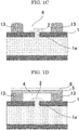
- FIG. 1A is an exemplary cross-sectional view of a duct 1 in which a liquid-leaked portion 1a (pinhole) is opened. A liquid 2 in the duct 1 leaks out from the liquid-leaked portion 1a.
- the first liquid leakage repair material 3 is cured by irradiation with active energy rays, to obtain a cured product 13 of the first liquid leakage repair material ( FIG. 1C ).
- a liquid reservoir 4 surrounded by the cured product 13 of the first liquid leakage repair material is formed around the liquid-leaked portion 1a.
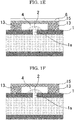
- a base material film 6 over which a second liquid leakage repair material 5, which is an active-energy-ray-curable composition, is applied is placed over the liquid reservoir 4 in a manner that the second liquid leakage repair material 5 contacts the cured product 13 of the first liquid leakage repair material but the second liquid leakage repair material 5 does not contact the liquid 2 that has leaked out from the liquid-leaked portion 1a, to thereby cover the liquid reservoir 4 with the second liquid leakage repair material 5 ( FIG. 1D ).
- the second liquid leakage repair material 5 is cured by irradiation of the second liquid leakage repair material 5 with active energy rays through the base material film 6, to obtain a cured product 15 of the second liquid leakage repair material ( FIG. 1E ). In this way, the liquid-leaked portion 1a can be covered with the cured product of the liquid leakage repair material.
- the base material film 6 is peeled ( FIG. 1F ).
- FIG. 2A is an exemplary top view of a duct 1 in which a liquid-leaked portion 1a (a linear through-hole such as a slit) is opened.
- a liquid-leaked portion 1a a linear through-hole such as a slit
- a liquid that has leaked out from the liquid-leaked portion 1a is wiped away with, for example, a waste cloth.
- a first liquid leakage repair material 3 which is an active-energy-ray-curable composition, is applied by spatula painting in a manner to cover a part of an overhead portion of the liquid-leaked portion 1a of the duct 1 ( FIG. 2B ). Then, the first liquid leakage repair material 3 is cured by irradiation with active energy rays.
- a second liquid leakage repair material which is an active-energy-ray-curable composition, is applied by spatula painting around the exposed part shrunk, in a manner that the second liquid leakage repair material does not contact the liquid that has leaked out from the exposed part shrunk.
- the second liquid leakage repair material is cured by irradiation with active energy rays, to obtain a cured product of the second liquid leakage repair material.
- a liquid reservoir surrounded by a cured product of the second liquid leakage repair material is formed around the exposed part shrunk.
- a base material film over which a third liquid leakage repair material, which is an active-energy-ray-curable composition, is applied is placed over the liquid reservoir in a manner that the third liquid leakage repair material contacts the cured product of the second liquid leakage repair material but the third liquid leakage repair material does not contact the liquid that has leaked out from the exposed part shrunk, to thereby cover the liquid reservoir with the third liquid leakage repair material.
- a third liquid leakage repair material which is an active-energy-ray-curable composition
- the third liquid leakage repair material is cured by irradiation of the third liquid leakage repair material with active energy rays through the base material film, to obtain a cured product of the third liquid leakage repair material.
- the exposed part shrunk can be covered with the cured product of the liquid leakage repair material.
- the base material film is peeled.
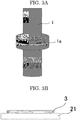
- a joint portion (flange portion) of a duct 1 is a liquid-leaked portion 1a ( FIG. 3A ).
- a light transmissive film 21 over which a first liquid leakage repair material 3 is applied is prepared ( FIG. 3B ).
- the light transmissive film 21 include a silicone sheet and a polytetrafluoroethylene (PTFE) sheet.
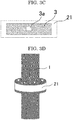
- the first liquid leakage repair material 3, which is an active-energy-ray-curable composition is applied over the light transmissive film 21, the light transmissive film 21 has an un-applied part 3a which is surrounded by the first liquid leakage repair material 3 but over which the first liquid leakage repair material 3 is not applied ( FIG. 3C ).
- FIG. 3B is an exemplary cross-sectional view and FIG. 3C is an exemplary top view.
- the light transmissive film 21 is pasted in a manner to cover the liquid-leaked portion 1a of the duct 1 ( FIG. 3D ). Then, the first liquid leakage repair material 3 is cured by irradiation with active energy rays through the light transmissive film 21, to obtain a cured product 13 of the first liquid leakage repair material 3.
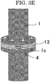
- the light transmissive film 21 is peeled ( FIG. 3E ).
- a liquid reservoir 4 is formed around an exposed part 1c of the liquid-leaked portion 1a, which is a remaining part of the liquid-leaked portion other than a part.
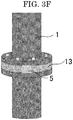
- a second liquid leakage repair material 5 which is an active-energy-ray-curable composition, is disposed in a manner to cover the liquid reservoir 4 ( FIG. 3F ).
- the second liquid leakage repair material 5 is cured by irradiation of the second liquid leakage repair material 5 with active energy rays, to obtain a cured product 15 of the second liquid leakage repair material ( FIG. 3G ).
- the sheet illustrated in FIG. 3C is pasted over the liquid-leaked portion and the liquid leakage repair material is cured, to thereby form the liquid reservoir in a one-step process.
- a liquid reservoir may be formed in the manner described below.
- a light transmissive film 21 over which a first liquid leakage repair material 3 is applied as illustrated in FIG. 4A is prepared.
- the first liquid leakage repair material 3, which is an active-energy-ray-curable composition is applied over the light transmissive film 21, because the first liquid leakage repair material 3 is applied dividedly over the light transmissive film 21, the light transmissive film 21 has an un-applied part 3a over which the first liquid leakage repair material 3 is not applied, between the divided sections ( FIG. 4A ).
- the light transmissive film 21 is pasted in a manner to cover the liquid-leaked portion 1a of the duct 1. Further, the first liquid leakage repair material 3 is cured by irradiation with active energy rays through the light transmissive film 21, to obtain a cured product 13 of the first liquid leakage repair material 3.
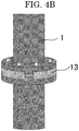
- the light transmissive film 21 is peeled ( FIG. 4B ). As a result, a part of the liquid-leaked portion 1a is covered with the cured product 13 of the first liquid repair material 3.
- the first liquid leakage repair material 3 is applied above and below the exposed part of the liquid-leaked portion 1a and over the cured product 13 of the first liquid leakage repair material 3 near the exposed part ( FIG. 4C ).
- the first liquid leakage repair material 3 is cured by irradiation of the first liquid leakage repair material 3 with active energy rays, to obtain a cured product 13 of the liquid leakage repair material 3 ( FIG. 4D ).
- a liquid reservoir 4 is formed around the exposed part 1c of the liquid-leaked portion 1a, which is a remaining part of the liquid-leaked portion 1a other than the part.
- a second liquid leakage repair material 5 which is an active-energy-ray-curable composition, is disposed in a manner to cover the liquid reservoir 4 ( FIG. 4E ).
- the second liquid leakage repair material 5 is cured by irradiation of the second liquid leakage repair material 5 with active energy rays, to obtain a cured product 15 of the second liquid leakage repair material ( FIG. 4F ).
- the viscosity of the first liquid leakage repair material is sufficiently high, for example, when the first liquid leakage repair material is putty and can form a liquid reservoir without being cured, a liquid leakage repairing method described below may be employed.
- the first liquid leakage repair material which is a curable composition, is disposed around a liquid-leaked portion of a duct, to thereby form a liquid reservoir.
- a second liquid leakage repair material which is a curable composition, is disposed in a manner to cover the liquid reservoir. Then, the first liquid leakage repair material and the second liquid leakage repair material are cured.
- An active-energy-ray-curable composition serving as a liquid leakage repair material was produced in the same manner as in Example 1, except that unlike in Example 1, the prescription was changed to as described in Table 1-1 to Table 1-4.
- the viscosity was measured using a rheometer. Specifically, the viscosity was measured using AR-G2 obtained from TA Instruments, Inc., and a cone plate having a diameter of 20 mm and an angle of 2 degrees in an environment at a temperature of 25 degrees C at a shear velocity of 0.1 s -1 .
- the liquid leakage repair material was filled in a mold formed of a silicone resin and having a size of 10 mm ⁇ 10 mm and a depth of 5 mm and the surface of the liquid leakage repair material was covered with releasable PET having a thickness of 50 micrometers.
- the liquid leakage repair material was cured by irradiation using a metal halide lamp until an integrated light quantity of 3 J/cm 2 at 365 nm, to produce a cured product.
- the cured product was taken out from the mold and the weight of the cured product was measured as a weight before liquid absorption.
- the cured product was put in a glass bottle. Further, an insulating oil was poured into the glass bottle in an amount enough to soak the whole cured product. Then, the cured product in the glass bottle was left to stand at room temperature (25 degrees C) for 24 hours, and the weight of the cured product that had absorbed the insulating oil was measured as a weight after liquid absorption.
- a high-pressure insulating oil A obtained from JXTG Energy Corporation (one kind of an insulating oil A compliant with JIS C2320) was used.
- liquid absorption rate 100 ⁇ weight after liquid absorption ⁇ weight before liquid absorption / weight before liquid absorption
- the curing speed was measured with a HAKKE MARS rheometer obtained from Thermo Fisher Scientific Inc. The curing speed was measured using a parallel plate having a diameter of 8 mm at a shear velocity of 0.1 s -1 at a UVLED illuminance of 50 mW/cm 2 (365 nm). UV irradiation was performed with pre-idling for 1 minute, irradiation for 1 minute, and post-idling for 1 minute. The curing time was evaluated based on the time (minute) taken until G' (storage modulus) reached 0.07 MPa (0.2 MPa or greater when converted to E'), seeing the timing, at which the pre-idling for 1 minute had passed, as 0 minutes. The curing speed was evaluated according to the evaluation criteria described below.
- a circular mold formed of a silicone resin and having an inner diameter of 6 mm and a thickness of 2 mm was put on a SUS304 plate and filled with the liquid leakage repair material, and the liquid leakage repair material was cured by irradiation using a metal halide lamp until an integrated light quantity of 3 J/cm 2 (365 nm). Subsequently, the mold formed of the silicone resin was removed, to produce a test piece (i.e., a cured product of the liquid leakage repair material adhering to the SUS304 plate, with a diameter of 6 mm and a thickness of 2 mm).
- test piece was tested at a test speed of 0.2 mm/s at a descending speed of 0.2 mm/s at a test height of 10.0 micrometers, to measure the shear adhesive strength.
- the shear adhesive strength was evaluated according to the evaluation criteria described below.
- a test device that would leak a liquid (an oil) by about 0.1 cc per minute was produced by inserting a stainless steel wire having a diameter of 0.5 mm into the packing of the flange portion of the pressure vessel illustrated in FIG. 5 and applying an air pressure of 0.2 MPa to the vessel. A liquid leakage seal test was performed using this test device.
- a high-pressure insulating oil A obtained from JXTG Energy Corporation (one kind of an insulating oil A compliant with JIS C2320) was used.
- the liquid leakage repair material was applied over the liquid-leaked portion from which the liquid was leaking at the liquid leaking speed described above in a manner to sufficiently cover the liquid-leaked portion, and cured by irradiation using a metal halide lamp until the integrated light quantity of 3 J/cm 2 at 365 nm. Then, the liquid leaking condition after one hour was visually observed and evaluated according to the evaluation criteria described below.
- Comparative Example 1 the prescription did not contain a filler and the liquid absorption rate (%) of the cured product (after curing) was 10% or higher. Due to these factors, liquid leakage was observed in the liquid leakage seal test.
- the cured products of the liquid leakage repair materials of Examples 1 to 14 had a liquid absorption rate (%) of lower than 10% (after curing). Therefore, the liquid leakage repair materials exhibited a good result in the liquid leakage seal test, and were confirmed to be capable of blocking liquid leakage easily and highly reliably.
- the inorganic filler content of 20% by mass or greater contributed to improvement of the shear adhesive strength compared with when no inorganic filler was contained (Comparative Example 1).
- mica had a great effect of improving the shear adhesive strength.
- the liquid leakage repairing method described below was performed using the active-energy-ray-curable composition of Example 10 as the first liquid leakage repair material and the second liquid leakage repair material.
- a duct 1 having a liquid-leaked portion 1a (a pinhole with a diameter of 1 mm) as illustrated in FIG. 1A was prepared.
- the duct 1 was filled with a liquid 2 (a mixture of a high-pressure insulating oil A obtained from JXTG Energy Corporation (one kind of an insulating oil A compliant with JIS C2320) and water at a mass ratio of 1:1), and the liquid 2 in the duct 1 was leaking out from the liquid-leaked portion 1a.
- a liquid 2 a mixture of a high-pressure insulating oil A obtained from JXTG Energy Corporation (one kind of an insulating oil A compliant with JIS C2320) and water at a mass ratio of 1:1
- the first liquid leakage repair material 3 which was an active-energy-ray-curable composition, was applied by spatula painting in a cylindrical shape [having an outer diameter of 5 mm, an inner diameter of 3 mm, and a height (thickness) of 5 mm] around the liquid-leaked portion 1a of the duct 1 in a manner that the first liquid leakage repair material 3 would not contact the liquid 2 that had leaked out from the liquid-leaked portion 1a ( FIG. 1B ).
- the first liquid leakage repair material 3 was cured by irradiation of active energy rays (a light quantity of 3 J/cm 2 at 365 nm) using a UV-LED lamp (365 nm), to obtain a cured product 13 of the first liquid leakage repair material ( FIG. 1C ). In this way, a liquid reservoir 4 surrounded by the cured product 13 of the first liquid leakage repair material was formed around the liquid-leaked portion 1a.
- a base material film 6 (a transparent PET film having a thickness of 50 micrometers) over which the second liquid leakage repair material 5, which was an active-energy-ray-curable composition, was applied with a thickness of 2 mm was placed over the liquid reservoir 4 in a manner that the second liquid leakage repair material 5 would contact the cured product 13 of the first liquid leakage repair material but the second liquid leakage repair material 5 would not contact the liquid 2 that had leaked out from the liquid-leaked portion 1a, to thereby cover the liquid reservoir 4 with the second liquid leakage repair material 5 ( FIG. 1D ).
- the second liquid leakage repair material 5 was cured by irradiation of the second liquid leakage repair material 5 with active energy rays (a light quantity of 3 J/cm 2 at 365 nm) through the base material film 6 using a UV-LED lamp (365 nm), to obtain a cured product 15 of the second liquid leakage repair material ( FIG. 1E ). In this way, the liquid-leaked portion 1a was covered with a cured product of the liquid leakage repair material.
- liquid leakage of the duct was repaired by the liquid leakage repairing method of the first embodiment of the present invention.
- the liquid leakage repair material no oil content permeated the liquid leakage repair material. Therefore, the liquid-leaked portion was successfully repaired with a cured product having a stable curability. That is, liquid leakage was successfully prevented with a remarkable ease and with a remarkably high reliability.
- Liquid leakage of a duct was repaired by the same operation as in Example 15, except that unlike in Example 15, UV REPAIR PEN GON-FU1 (obtained from Fiberfix Japan), which was an acrylic-based active-energy-ray-curable composition, was used as the first liquid leakage repair material and the second liquid leakage repair material, and the integrated light quantity of active energy rays emitted to the first liquid leakage repair material and the second liquid leakage repair material was changed to 10 J/cm 2 . Although a greater integrated light quantity than in Example 15 was needed for curing the first liquid leakage repair material and the second liquid leakage repair material, no oil content permeated the liquid leakage repair materials when curing the liquid leakage repair materials. Therefore, the liquid-leaked portion was successfully repaired with cured products having a stable curability. That is, liquid leakage was successfully prevented with easily and highly reliably
- the liquid leakage repairing method described below was performed using the active-energy-ray-curable composition of Example 8 as the first liquid leakage repair material, the second liquid leakage repair material, and the third liquid leakage repair material.
- a duct 1 having a liquid-leaked portion 1a (with a rectangular shape having a width of 1 mm and a length of 5 cm) as illustrated in FIG. 2A was prepared.
- the duct 1 was filled with a liquid (a mixture of a high-pressure insulating oil A obtained from JXTG Energy Corporation (one kind of an insulating oil A compliant with JIS C2320) and water at a mass ratio of 1:1), and the liquid in the duct 1 was leaking out from the liquid-leaked portion 1a.
- the first liquid leakage repair material 3 which was an active-energy-ray-curable composition, was applied by spatula painting in a manner to cover a part of the overhead portion of the liquid-leaked portion 1a of the duct 1.
- the first liquid leakage repair material 3 was cured by irradiation with active energy rays (a light quantity of 3 J/cm 2 at 365 nm) using a UV-LED lamp (365 nm).
- the application and the curing were repeated at another part of the liquid-leaked portion, to shape the liquid-leaked portion to have a size of about 1 mm ⁇ 1 mm. In this way, the exposed part of the liquid-leaked portion 1a was shrunk with the cured product of the first liquid leakage repair material.
- the second liquid leakage repair material which was an active-energy-ray-curable composition, was applied by spatula painting around the exposed part shrunk in a manner that the second liquid leakage repair material would not contact the liquid that had leaked out from the exposed part shrunk.
- the second liquid leakage repair material was cured by irradiation with active energy rays, to obtain a cured product of the second liquid leakage repair material.
- a liquid reservoir surrounded by the cured product of the second liquid leakage repair material was formed around the exposed part shrunk.
- a base material film over which the third liquid leakage repair material, which was an active-energy-ray-curable composition, was applied was placed over the liquid reservoir in a manner that the third liquid leakage repair material would contact the cured product of the second liquid leakage repair material but the third liquid leakage repair material would not contact the liquid that had leaked out from the exposed part shrunk, to thereby cover the liquid reservoir with the third liquid leakage repair material.
- the third liquid leakage repair material was cured by irradiation of the third liquid leakage repair material with active energy rays through the base material film, to obtain a cured product of the third liquid leakage repair material.
- the exposed part shrunk was successfully covered with the cured product of the liquid leakage repair material.
- liquid leakage of the duct was repaired by the liquid leakage repairing method of the second embodiment of the present invention.
- the liquid contacted the liquid leakage repair materials, but the liquid absorption rate of the liquid leakage repair materials was low. Therefore, the liquid-leaked portion was successfully repaired with cured products having a stable curability. That is, liquid leakage was successfully prevented with a remarkable ease and with a remarkably high reliability.
- Liquid leakage of a duct was repaired by the same operation as in Example 17, except that unlike in Example 17, UV REPAIR PEN GON-FU1 (obtained from Fiberfix Japan), which was an acrylic-based active-energy-ray-curable composition, was used as the first liquid leakage repair material, the second liquid leakage repair material, and the third liquid leakage repair material, and the integrated light quantity of active energy rays emitted to the first liquid leakage repair material, the second liquid leakage repair material, and the third liquid leakage repair material was changed to 10 J/cm 2 .
- UV REPAIR PEN GON-FU1 obtained from Fiberfix Japan
- Example 17 Although a greater integrated light quantity than in Example 17 was needed for curing the first liquid leakage repair material, the second liquid leakage repair material, and the third liquid leakage repair material, the liquid-leaked portion was successfully repaired with cured products having a stable curability. That is, liquid leakage was successfully prevented with ease.
- the liquid leakage repairing method described below was performed using the active-energy-ray-curable composition of Example 5 as the first liquid leakage repair material and the second liquid leakage repair material.
- a joint portion (flange portion) of a duct 1 was a liquid-leaked portion 1a ( FIG. 3A ).
- a light transmissive film 21 (a silicone sheet with a length of 20 cm, a width of 2.5 cm, and a thickness of 2 mm) was prepared.
- the first liquid leakage repair material 3 was applied over the light transmissive film 21 to have a thickness of about 2 mm (FIG. B).
- the light transmissive film 21 had an un-applied part 3a (with a size of about 5 mm ⁇ 5 mm) which was surrounded by the first liquid leakage repair material 3 but over which the first liquid leakage repair material 3 was not applied ( FIG. 3C ).
- the light transmissive film 21 was pasted in a manner to cover the liquid-leaked portion 1a of the duct 1 ( FIG. 3D ). Then, the first liquid leakage repair material 3 was cured by irradiation with active energy rays (a light quantity of 3 J/cm 2 at 365 nm) through the light transmissive film 21 using a UV-LED lamp (365 nm), to obtain a cured product 13 of the first liquid leakage repair material 3.
- active energy rays a light quantity of 3 J/cm 2 at 365 nm
- the light transmissive film 21 was peeled ( FIG. 3E ).
- a liquid reservoir 4 was formed around an exposed part 1c of the liquid-leaked portion 1a, which was a remaining part of the liquid-leaked portion 1a other than one part of the liquid-leaked portion 1a.
- the second liquid leakage repair material 5 which was an active-energy-ray-curable composition, was disposed in a manner to cover the liquid reservoir 4 ( FIG. 3F ).
- the second liquid leakage repair material 5 was cured by irradiation of the second liquid leakage repair material 5 with active energy rays (a light quantity of 3 J/cm 2 at 365 nm) using a UV-LED lamp (365 nm), to obtain a cured product 15 of the second liquid leakage repair material ( FIG. 3G ).
- liquid leakage of the duct was repaired by the liquid leakage repairing method of the third embodiment of the present invention.
- the liquid contacted the liquid leakage repair materials, but the liquid absorption rate of the liquid leakage repair materials was low. Therefore, the liquid-leaked portion was successfully repaired with cured products having a stable curability. That is, liquid leakage was successfully prevented with a remarkable ease and with a remarkably high reliability.
- Liquid leakage of a duct was repaired by the same operation as in Example 19, except that unlike in Example 19, UV REPAIR PEN GON-FU1 (obtained from Fiberfix Japan), which was an acrylic-based active-energy-ray-curable composition, was used as the first liquid leakage repair material and the second liquid leakage repair material, and the integrated light quantity of active energy rays emitted to the first liquid leakage repair material and the second liquid leakage repair material was changed to 10 J/cm 2 . Although a greater integrated light quantity than in Example 19 was needed for curing the first liquid leakage repair material and the second liquid leakage repair material, the liquid-leaked portion was successfully repaired with cured products having a stable curability. That is, liquid leakage was successfully prevented with ease.
- UV REPAIR PEN GON-FU1 obtained from Fiberfix Japan
- the liquid leakage repair material of the present invention can be suitably used for repairing liquid leakage of a duct, because the liquid leakage repair material can block liquid leakage easily and highly reliably when a liquid leaks out from a duct through which a liquid is circulated.
- the liquid leakage repairing method of the present invention can be suitably used for repairing liquid leakage of a duct, because the liquid leakage repairing method can block liquid leakage easily and highly reliably when a liquid leaks out from a duct through which a liquid is circulated.
Landscapes
- Chemical & Material Sciences (AREA)
- Organic Chemistry (AREA)
- Health & Medical Sciences (AREA)
- Chemical Kinetics & Catalysis (AREA)
- Medicinal Chemistry (AREA)
- Polymers & Plastics (AREA)
- Engineering & Computer Science (AREA)
- Materials Engineering (AREA)
- Life Sciences & Earth Sciences (AREA)
- Wood Science & Technology (AREA)
- General Engineering & Computer Science (AREA)
- Mechanical Engineering (AREA)
- Physics & Mathematics (AREA)
- Plasma & Fusion (AREA)
- Pipe Accessories (AREA)
- Application Of Or Painting With Fluid Materials (AREA)
- Sealing Material Composition (AREA)
- Polymerisation Methods In General (AREA)
Abstract
Description
- The present invention relates to a liquid leakage repair material suitable for repairing a duct when a liquid leaks from a duct through which a liquid is circulated, a liquid leakage repairing method using the liquid leakage repair material and a duct repaired with the liquid leakage repair material.
- The present invention also relates to a liquid leakage repairing method suitable for repairing a duct when a liquid leaks from a duct through which a liquid is circulated.
- For example, a transformer equipped with a radiator is installed in, for example, a power plant or a transformer substation. The main body of the transformer and the radiator are coupled to each other through an oil pipeline, and an oil (e.g., an insulating oil) cooled with the radiator is circulated between the main body of the transformer and the radiator, to thereby cool the main body of the transformer.
- As a result of a long-year use of an oil pipeline, there may be a case where an oil leaks from the flange portion of the oil pipeline. Further, as a result of a long-year use of an oil pipeline, there may be a case where a hole such as a pinhole opens in the oil pipeline and an oil leaks from the hole.
- When oil leakage occurs, the oil may permeate the ground and constitute an indirect factor for pollution of the soil or the water quality. Particularly, insulating oils for old-type oil coolers may contain polybiphenyl chloride, which is an environmental hormone, and strict countermeasures are needed for leakage of oils in consideration of influences to the living things and the environment.
- Hence, in order to prevent oil outspill when an oil leaks from a flange portion, a proposed transformer oil outspill preventing cover includes an oil-resistant covering body for covering the outer circumference of a coupling flange, and a cooling oil collecting container coupled to a cooling oil outlet opened at the lower end of the covering body (for example, see PTL 1).
- However, this method cannot prevent outspill when an oil leaks from a portion other than the flange portion. Moreover, this method needs installation of, for example, the covering body and the collecting container, and lacks convenience.
- As a convenient outspill preventing method for when an oil leaks from a portion other than the flange portion, the oil-leaked portion may be blocked with a waste cloth (a piece of cloth).
- However, this method is no more than an emergency measure. When the waste cloth is fully soaked with the oil, it can no longer prevent additional oil leakage and lacks reliability as a measure for preventing outspill.
- A proposed gas/liquid leakage preventing method that enables leakage repair without evacuation of a gas or liquid from inside, for example, a metallic tank includes a step of attaching a seal material at a gas-leaked portion or a liquid-leaked portion, a step of attaching a putty material on the seal material, and a step of pasting a glass fiber-reinforced plastic (FRP) on the seal material and the putty material (for example, see PTL 2).
- However, this method needs at least three materials including the seal material, the putty material, and the glass fiber-reinforced plastic, and includes many steps. Therefore, this method lacks convenience.
- Hence, currently, a method that can block liquid leakage easily and highly reliably when a liquid leaks from a duct through which a liquid is circulated is demanded.
-
- PTL 1:
Japanese Patent Application Laid-Open (JP-A) No. 2001-338814 - PTL 2:
JP-A No. 2008-230643 - The present invention has an object to provide a liquid leakage repair material that can block liquid leakage easily and highly reliably when a liquid leaks from a duct though which a liquid is circulated, a liquid leakage repairing method using the liquid leakage repair material, a duct repaired with the liquid leakage repair material, and a liquid leakage repairing method that can block liquid leakage easily and highly reliably when a liquid leaks from a duct through which a liquid is circulated.
- Means for solving the above problems are as follows.
- <1> A liquid leakage repair material, including:
- a curable composition,
- wherein a liquid absorption rate of the liquid leakage repair material after cured is lower than 10%.
- <2> The liquid leakage repair material according to <1>,
wherein the liquid leakage repair material is free of stringiness. - <3> The liquid leakage repair material according to <1> or <2>,
wherein a viscosity of the liquid leakage repair material is 0.1 Pa·s or higher but 100,000 Pa·s or lower. - <4> The liquid leakage repair material according to any one of <1> to <3>, further including:
a filler. - <5> The liquid leakage repair material according to <4>,
- wherein the filler is an inorganic filler, and
- wherein the liquid leakage repair material contains the inorganic filler in an amount of 20% by mass or greater but 95% by mass or less.
- <6> The liquid leakage repair material according to any one of <1> to <5>, further including:
- a monofunctional (meth)acrylate represented by formula (1) below;
- a multifunctional (meth)acrylate; and
- a radical initiator,

- where in General formula (1), R1 represents a hydrogen atom or a methyl group, and R2 represents an organic group containing four or more carbon atoms.
- <7> The liquid leakage repair material according to any one of <1> to <6>,
wherein the curable composition is an active-energy-ray-curable composition. - <8> The liquid leakage repair material according to any one of <1>to <7>,
wherein the liquid leakage repair material has a shear adhesive strength of 0.15 MPa or greater. - <9> The liquid leakage repair material according to any one of <1> to <8>,
wherein when the liquid leakage repair material is cured, a time taken until a storage modulus G' of the liquid leakage repair material reaches 0.07 MPa is 0.50 minutes or shorter. - <10> A liquid leakage repairing method, including:
a step of applying the liquid leakage repair material according to any one of <1> to <9>, which is an active-energy-ray-curable composition, over a liquid-leaked portion of a duct, and irradiating the liquid leakage repair material with active energy rays to cure the liquid leakage repair material. - <11> A duct including a liquid-leaked portion, the duct including:
a cured product of the liquid leakage repair material according to any one of <1> to <9> over the liquid-leaked portion. - <12> A liquid leakage repairing method, including:
- a step of disposing a first liquid leakage repair material, which is a curable composition, around a liquid-leaked portion of a duct and curing the first liquid leakage repair material, to thereby form a liquid reservoir; and
- a step of disposing a second liquid leakage repair material, which is a curable composition, in a manner to cover the liquid reservoir and curing the second liquid leakage repair material.
- <13> A liquid leakage repairing method, including:
- a step of disposing a first liquid leakage repair material, which is a curable composition, at a part of a liquid-leaked portion of a duct and curing the first liquid leakage repair material, to thereby shrink an exposed part of the liquid-leaked portion;
- a step of disposing a second liquid leakage repair material, which is a curable composition, around the exposed part shrunk and curing the second liquid leakage repair material, to thereby form a liquid reservoir; and
- a step of disposing a third liquid leakage repair material, which is a curable composition, in a manner to cover the liquid reservoir and curing the third liquid leakage repair material.
- <14> A liquid leakage repairing method, including:
- a step of disposing a cured product of a first liquid leakage repair material, which is a curable composition, at a part of a liquid-leaked portion of a duct and also disposing the cured product around an exposed part of the liquid-leaked portion, which is a remaining part of the liquid-leaked portion other than the part, to thereby form a liquid reservoir; and
- a step of further disposing a second liquid leakage repair material, which is a curable composition, in a manner to cover the liquid reservoir and curing the second liquid leakage repair material.
- <15> The liquid leakage repairing method according to any one of <12> to <14>,
wherein the first liquid leakage repair material is an active-energy-ray-curable composition, and
wherein the second liquid leakage repair material is an active-energy-ray-curable composition. - <16> The liquid leakage repairing method according to <13>,
wherein the first liquid leakage repair material is an active-energy-ray-curable composition,
wherein the second liquid leakage repair material is an active-energy-ray-curable composition, and
wherein the third liquid leakage repair material is an active-energy-ray-curable composition. - <17> The liquid leakage repairing method according to any one of <12> to <14>,
wherein the first liquid leakage repair material and the second liquid leakage repair material are each the liquid leakage repair material according to any one of <1> to <9>. - <18> The liquid leakage repairing method according to <13>,
wherein the first liquid leakage repair material, the second liquid leakage repair material, and the third liquid leakage repair material are each the liquid leakage repair material according to any one of <1> to <9>. - The present invention can provide a liquid leakage repair material that can block liquid leakage easily and highly reliably when a liquid leaks from a duct though which a liquid is circulated, a liquid leakage repairing method using the liquid leakage repair material, a duct repaired with the liquid leakage repair material, and a liquid leakage repairing method that can block liquid leakage easily and highly reliably when a liquid leaks from a duct through which a liquid is circulated.
-
-
FIG. 1A is an exemplary cross-sectional view for illustrating an example of a liquid leakage repairing method of the present invention (first embodiment) (part 1); -
FIG. 1B is an exemplary cross-sectional view for illustrating an example of a liquid leakage repairing method of the present invention (first embodiment) (part 2); -
FIG. 1C is an exemplary cross-sectional view for illustrating an example of a liquid leakage repairing method of the present invention (first embodiment) (part 3); -
FIG. 1D is an exemplary cross-sectional view for illustrating an example of a liquid leakage repairing method of the present invention (first embodiment) (part 4); -
FIG. 1E is an exemplary cross-sectional view for illustrating an example of a liquid leakage repairing method of the present invention (first embodiment) (part 5); -
FIG. 1F is an exemplary cross-sectional view for illustrating an example of a liquid leakage repairing method of the present invention (first embodiment) (part 6); -
FIG. 2A is an exemplary cross-sectional view for illustrating an example of a liquid leakage repairing method of the present invention (second embodiment) (part i); -
FIG. 2B is an exemplary cross-sectional view for illustrating an example of a liquid leakage repairing method of the present invention (second embodiment) (part 2); -
FIG. 2C is an exemplary cross-sectional view for illustrating an example of a liquid leakage repairing method of the present invention (second embodiment) (part 3); -
FIG. 3A is an exemplary cross-sectional view for illustrating an example of a liquid leakage repairing method of the present invention (third embodiment) (part 1); -
FIG. 3B is an exemplary cross-sectional view for illustrating an example of a liquid leakage repairing method of the present invention (third embodiment) (part 2); -
FIG. 3C is an exemplary cross-sectional view for illustrating an example of a liquid leakage repairing method of the present invention (third embodiment) (part 3); -
FIG. 3D is an exemplary cross-sectional view for illustrating an example of a liquid leakage repairing method of the present invention (third embodiment) (part 4); -
FIG. 3E is an exemplary cross-sectional view for illustrating an example of a liquid leakage repairing method of the present invention (third embodiment) (part 5); -
FIG. 3F is an exemplary cross-sectional view for illustrating an example of a liquid leakage repairing method of the present invention (third embodiment) (part 6); -
FIG. 3G is an exemplary cross-sectional view for illustrating an example of a liquid leakage repairing method of the present invention (third embodiment) (part 7); -
FIG. 4A is an exemplary cross-sectional view for illustrating another example of a liquid leakage repairing method of the present invention (third embodiment) (part 1); -
FIG. 4B is an exemplary cross-sectional view for illustrating another example of a liquid leakage repairing method of the present invention (third embodiment) (part 2); -
FIG. 4C is an exemplary cross-sectional view for illustrating another example of a liquid leakage repairing method of the present invention (third embodiment) (part 3); -
FIG. 4D is an exemplary cross-sectional view for illustrating another example of a liquid leakage repairing method of the present invention (third embodiment) (part 4); -
FIG. 4E is an exemplary cross-sectional view for illustrating another example of a liquid leakage repairing method of the present invention (third embodiment) (part 5); -
FIG. 4F is an exemplary cross-sectional view for illustrating another example of a liquid leakage repairing method of the present invention (third embodiment) (part 6); and -
FIG. 5 is an image of a pressure vessel used for a liquid leakage seal test. - A liquid leakage repair material of the present invention is a curable composition.
- A liquid absorption rate of the liquid leakage repair material after cured is lower than 10%. That is, a cured product of the liquid leakage repair material has a liquid absorption rate of lower than 10%.
- The target liquid to be prevented from leakage by the liquid leakage repair material is not particularly limited and may be appropriately selected depending on the intended purpose. The liquid may be water or an oil.
- The liquid leakage repair material is a curable composition. Therefore, it can be easily applied over a portion to be repaired, making it possible to block liquid leakage easily.
- The liquid absorption rate of the liquid leakage repair material after cured is lower than 10%. Therefore, the liquid leakage absorption material after cured has an extremely low liquid absorption and a high liquid leakage seal property. Hence, the liquid leakage repair material can block liquid leakage highly reliably.
- The liquid absorption rate of the liquid leakage repair material after cured is not particularly limited and may be appropriately selected depending on the intended purpose so long as it is lower than 10%. For example, it may be higher than 0% but lower than 10%, or 0.5% or higher but 5.0% or lower.
- For example, the liquid absorption rate of the liquid leakage repair material after cured can be obtained in the manner described below.
- The liquid leakage repair material is filled in a mold formed of a silicone resin and having a size of 10 mm × 10 mm and a depth of 5 mm and the surface of the liquid leakage repair material is covered with releasable polyethylene terephthalate (PET) having a thickness of 50 micrometer. In this state, the curable composition is cured, to produce a cured product. The cured product is taken out from the mold and the weight of the cured product is measured as a weight before liquid absorption.
- The cured product is put in a glass bottle. Further, a liquid is poured into the glass bottle in an amount enough to soak the whole cured product. Then, the cured product in the glass bottle is left to stand at room temperature (25 degrees C) for 24 hours, and the weight of the cured product that has absorbed the liquid is measured as a weight after liquid absorption. As the liquid, for example, a high-pressure insulating oil A available from JXTG Energy Corporation (one kind of an insulating oil A compliant with JIS C2320) is used.
- The liquid absorption rate is calculated according to the formula below.

- When the curable composition is an active-energy-ray-curable composition, the active-energy-ray-curable composition is cured by irradiation using a metal halide lamp until an integrated light quantity of 3 J/cm2 at 365 nm.
- It is preferable that the liquid leakage repair material be free of stringiness in terms of easy handleability. "Free of stringiness" can be confirmed by whether or not the liquid leakage repair material becomes stringy or not when the liquid leakage repair material is removed from a stainless steel spatula after the surface of the liquid leakage repair material is kept in contact with the spatula for 0.5 seconds, i.e., whether the spatula and the liquid leakage repair material physically connect with each other or not.
- The viscosity of the liquid leakage repair material is not particularly limited, may be appropriately selected, and is preferably 0.1 Pa·s or higher but 100,000 Pa·s or lower.
- The viscosity can be measured with, for example, a rheometer. Specifically, the viscosity is measured with AR-G2 available from TA Instruments, Inc., using a cone plate having a diameter of 20 mm and an angle of 2 degrees in an environment at a temperature of 5 degrees C at a shear velocity of 0.1 s-1.
- The shear adhesive strength of the liquid leakage repair material is preferably 0.15 MPa or greater. With such a shear adhesive strength, the liquid leakage repair material has an excellent adhesiveness. The upper limit of the shear adhesive strength is not particularly limited and may be appropriately selected depending on the intended purpose. For example, the shear adhesive strength is 2.00 MPa or less.
- For example, the shear adhesive strength can be measured by the method described below.
- A circular mold formed of a silicone resin and having an inner diameter of 6 mm and a thickness of 2 mm is put on a SUS304 plate and filled with the liquid leakage repair material, and the liquid leakage repair material is cured. Subsequently, the mold formed of the silicone resin is removed, to produce a test piece (i.e., a cured product of the liquid leakage repair material adhering to the SUS304 plate, with a diameter of 6 mm and a thickness of 2 mm).
- Then, using a universal bond tester 400 PLUS available from Nordson Dage Corporation, the test piece is tested at a test speed of 0.2 mm/s at a descending speed of 0.2 mm/s at a test height of 10.0 micrometers, to measure the shear adhesive strength.
- When the curable composition is an active-energy-ray-curable composition, the active-energy-ray-curable composition is cured by irradiation using a metal halide lamp until an integrated light quantity of 3 J/cm2 at 365 nm.
- It is preferable that when the liquid leakage repair material is cured, a time taken until a storage modulus G' of the liquid leakage repair material reaches 0.07 MPa is 0.50 minutes or shorter. With such a property, the liquid leakage repair material has an excellent fast curability.
- For example, the time taken until the storage modulus G' reaches 0.07 MPa can be measured by the method described below.
- The curing speed is measured with a HAKKE MARS rheometer available from Thermo Fisher Scientific Inc. The curing speed is measured using a parallel plate having a diameter of 8 mm at a shear velocity of 0.1 s-1 at a UVLED illuminance of 50 mW/cm2 (365 nm). UV irradiation is performed with pre-idling for 1 minute, irradiation for 1 minute, and post-idling for 1 minute. The curing time is evaluated based on the time (minute) taken until G' (storage modulus) reaches 0.07 MPa (0.2 MPa or greater when converted to E'), seeing the timing, at which the pre-idling for 1 minute has passed, as 0 minutes.
- G' represents a storage modulus under a shear stress, and E' represents a storage modulus under a uniaxial stress (tension/compression). G' and E' have a relationship of E'=3G'.
- It is preferable that the liquid leakage repair material contain a filler.
- When the liquid leakage repair material contains the filler, the liquid absorption rate of the liquid leakage repair material after cured can be reduced.
- Examples of the filler include an inorganic filler and an organic filler. An inorganic filler is preferable in terms of weather resistance.
- Examples of the organic filler include polyurethane resin particles, polyimide resin particles, benzoguanamine resin particles, and epoxy resin particles.
- Surface treatment may be applied to the organic filler.
- One of these organic fillers may be used alone or two or more of these organic materials may be used in combination.
- The inorganic filler is not particularly limited and may be appropriately selected depending on the intended purpose.
- The material of the inorganic filler is not particularly limited and may be appropriately selected depending on the intended purpose. Examples of the material of the inorganic filler include silica (silicon oxide), mica, talc, barium sulfate, aluminum hydroxide, aluminum oxide, magnesium hydroxide, magnesium oxide, titanium oxide, zinc oxide, and iron oxide. Among these materials, silica, mica, and talc are preferable and mica is more preferable in terms of an excellent adhesiveness with the repair target.
- Surface treatment may be applied to the inorganic filler.
- One of these inorganic fillers may be used alone or two or more of these inorganic fillers may be used in combination.
- The average particle diameter of the filler is not particularly limited, may be appropriately selected depending on the intended purpose, and is preferably 1 micrometer or greater but 100 micrometers or less.
- For example, the average particle diameter can be measured as D50 by a laser diffraction method.
- The content of the filler in the liquid leakage repair material is not particularly limited, may be appropriately selected depending on the intended purpose, and is preferably 20% by mass or greater but 95% by mass or less, more preferably 30% by mass or greater but 93% by mass or less, and particularly preferably 40% by mass or greater but 93% by mass or less in terms of an excellent adhesiveness with the repair target.
- The liquid leakage repair material may contain other components so long as the function of the present invention is not spoiled. Examples of the other components include a surface conditioner, a dispersant, and a pigment.
- The curable composition may be a thermosetting composition, or an active-energy-ray-curable composition, or a thermosetting, active-energy-ray-curable composition. An active-energy-ray-curable composition is preferable in terms of fast curability and a greater repairing convenience.
- It is preferable that the curable composition contain a monofunctional (meth)acrylate represented by General formula (1) below, a multifunctional (meth)acrylate, and a radical initiator.
- (Meth)acrylate represents acrylate and methacrylate.
-

- In General formula (1), R1 represents a hydrogen atom or a methyl group, and R2 represents an organic group containing four or more carbon atoms.
- The organic group of R2 may be straight-chained or branched-chained, or may have a cyclic structure.
- The number of carbon atoms contained in the organic group is preferably 4 or greater, more preferably 8 or greater, and particularly preferably 10 or greater. The upper limit of the number of carbon atoms contained in the organic group is not particularly limited, and may be appropriately selected depending on the intended purpose. For example, the number of carbon atoms contained in the organic group may be 30 or less, or 20 or less.
- The organic group may contain a heteroatom or may be free of a heteroatom. The heteroatom is not particularly limited and may be appropriately selected depending on the intended purpose so long as the heteroatom is an atom other than a carbon atom and a hydrogen atom. Examples of the heteroatom include an oxygen atom and a nitrogen atom.
- The organic group may contain a hydroxyl group or may be free of a hydroxyl group.
- It is preferable that the organic group be a hydrocarbon group.
- Examples of the monofunctional (meth)acrylate represented by General formula (1) include aliphatic monofunctional (meth)acrylate, alicyclic monofunctional (meth)acrylate, and aromatic monofunctional (meth)acrylate.
- Examples of the aliphatic monofunctional (meth)acrylate include decyl (meth)acrylate, isodecyl (meth)acrylate, lauryl (meth)acrylate, stearyl (meth)acrylate, and isostearyl (meth)acrylate.
- One of these aliphatic monofunctional (meth)acrylates may be used alone or two or more of these aliphatic monofunctional (meth)acrylates may be used in combination.
- Examples of the alicyclic monofunctional (meth)acrylate include isobornyl (meth)acrylate, dicyclopentenyl (meth)acrylate, and tricyclodecanyl (meth)acrylate.
- One of these alicyclic monofunctional (meth)acrylates may be used alone or two or more of these alicyclic monofunctional (meth)acrylates may be used in combination.
- The content of the monofunctional (meth)acrylate represented by General formula (1) above in the curable composition, which is the liquid leakage repair material, is not particularly limited, may be appropriately selected depending on the intended purpose, and is preferably 5% by mass or greater but 70% by mass or less, more preferably 10% by mass or greater but 65% by mass or less, and particularly preferably 20% by mass or greater but 50% by mass or less.
- The content of the monofunctional (meth)acrylate represented by General formula (1) above in the curable composition, which is the liquid leakage repair material, is preferably 40% by mass or greater but 99% by mass or less, more preferably 50% by mass or greater but 99% by mass or less, and particularly preferably 80% by mass or greater but 98% by mass or less relative to all (meth)acrylates in the curable composition.
- The multifunctional (meth)acrylate is not particularly limited and may be appropriately selected depending on the intended purpose so long as the multifunctional (meth)acrylate is a bifunctional or higher (meth)acrylate. Examples of the multifunctional (meth)acrylate include bifunctional (meth)acrylate, trifunctional (meth)acrylate, and tetrafunctional (meth)acrylate.
- One of these multifunctional (meth)acrylates may be used alone or two or more of these multifunctional (meth)acrylates may be used in combination.
- Examples of the multifunctional (meth)acrylate include multifunctional (meth)acrylate containing a chain aliphatic hydrocarbon group, multifunctional (meth)acrylate containing an alicyclic group, and multifunctional (meth)acrylate containing an aromatic group.
- Examples of the bifunctional (meth)acrylate include ethylene glycol di(meth)acrylate, diethylene glycol di(meth)acrylate, tetraethylene glycol di(meth)acrylate, polyethylene glycol di(meth)acrylate, propylene glycol di(meth)acrylate, dipropylene glycol di(meth)acrylate, polypropylene glycol di(meth)acrylate, butylene glycol di(meth)acrylate, neopentyl glycol di(meth)acrylate, ethylene oxide-modified bisphenol A-type di(meth)acrylate, propylene oxide-modified bisphenol A-type di(meth)acrylate, 1,6-hexanediol di(meth)acrylate, glycerin di(meth)acrylate, pentaerythritol di(meth)acrylate, ethylene glycol diglycidyl ether di(meth)acrylate, diethylene glycol diglycidyl ether di(meth)acrylate, tricyclodecane dimethanol di(meth)acrylate, phthalic acid diglycidyl ester di(meth)acrylate, hydroxypivalic acid-modified neopentyl glycol di(meth)acrylate, and urethane di(meth)acrylate.
- One of these bifunctional (meth)acrylates may be used alone or two more of these bifunctional (meth)acrylates may be used in combination.
- Examples of the trifunctional (meth)acrylate include trimethylolpropane tri(meth)acrylate, pentaerythritol tri(meth)acrylate, and tri(meth)acryloyloxyethoxy trimethylolpropane.
- One of these trifunctional (meth)acrylates may be used alone or two or more of these trifunctional (meth)acrylates may be used in combination.
- Examples of the tetrafunctional (meth)acrylate include pentaerythritol tetra(meth)acrylate.
- One of these tetrafunctional (meth)acrylates may be used alone or two or more of these tetrafunctional (meth)acrylates may be used in combination.
- Examples of the pentafunctional or higher (meth)acrylate include dipentaerythritol penta(meth)acrylate and dipentaerythritol hexa(meth)acrylate.
- One of these pentafunctional or higher (meth)acrylates may be used alone or two or more of these pentafunctional or higher (meth)acrylates may be used in combination.
- The content of the multifunctional (meth)acrylate in the curable composition, which is the liquid leakage repair material, is not particularly limited, may be appropriately selected depending on the intended purpose, and is preferably greater but 0% by mass but 30% by mass or less, more preferably 0.5% by mass or greater but 15% by mass or less, and particularly preferably 1% by mass or greater but 5% by mass or less.
- The content of the multifunctional (meth)acrylate in the curable composition, which is the liquid leakage repair material, is preferably 0.5% by mass or greater but 60% by mass or less, more preferably 1% by mass or greater but 50% by mass or less, and particularly preferably 3% by mass or greater but 15% by mass or less relative to all (meth)acrylates in the curable composition.
- Examples of the radical initiator include a thermal radical initiator and a photo radical initiator.
- Examples of the photo radical initiator include benzophenones, benzyl ketals, dialkoxy acetophenones, hydroxyalkyl acetophenones, aminoalkylphenones, and acylphosphine oxides. Specific examples of the photo radical initiator include benzophenone, methyl benzophenone, 4-phenyl benzophenone, 4,4'-bis(dimethylamino)benzophenone, 4,4'-bis(diethylamino)benzophenone, benzyl, 2,2-dimethoxy-2-phenyl acetophenone, dimethoxyacetophenone, diethoxyacetophenone, 2-hydroxy-2-methyl-1-phenylpropan-1-one, 2-benzyl-2-dimethylamino-1-(4-morpholinophenyl)-butan- 1-one, 2-methyl-1-[4-(methoxythio)-phenyl]-2-morpholinopropan-2-one, 1-hydroxy-cyclohexyl-phenyl ketone, diphenylacylphenyl phosphine oxide, diphenyl(2,4,6-trimethylbenzoyl)phosphine oxide, 2,4,6-trimethylbenzoylethoxyphenylphosphine oxide, and bis(2,4,6-trimethylbenzoyl)phenylphosphine oxide.
- One of these photo radical initiators may be used alone or two or more of these photo radical initiators may be used in combination.
- The content of the radical initiator in the curable composition, which is the liquid leakage repair material, is not particularly limited, may be appropriately selected depending on the intended purpose, and is preferably 0.1% by mass or greater but 5% by mass or less, more preferably 0.5% by mass or greater but 4% by mass or less, and particularly preferably 1% by mass or greater but 3% by mass or less relative to all (meth)acrylates in the curable composition.
- The method for curing the curable composition is not particularly limited and may be appropriately selected depending on the intended purpose. The curable composition is an active-energy-ray-curable composition. A method of curing the active-energy-ray-curable composition by irradiation with active energy rays is preferable. The active energy rays are not particularly limited and may be appropriately selected depending on the intended purpose. Examples of the active energy rays include electron beams, ultraviolet rays, infrared rays, laser light beams, visible light rays, ionizing radiations (e.g., X rays, α rays, β rays, and γ rays), microwaves, and high-frequency waves.
- One embodiment of the liquid leakage repairing method of the present invention includes at least a curing step and further includes other steps as needed.
- The curing step is not particularly limited and may be appropriately selected depending on the intended purpose so long as the curing step is a step of applying the liquid leakage repair material of the present invention, which is an active-energy-ray-curable composition, over a liquid-leaked portion of a duct, and irradiating the liquid leakage repair material with active energy rays to cure the liquid leakage repair material.
- The duct is not particularly limited and may be appropriately selected depending on the intended purpose so long as the duct is a duct configured to send a liquid, and examples of the duct include a duct configured to send an insulating oil between a radiator and a transformer.
- The material of the duct is not particularly limited and may be appropriately selected depending on the intended purpose so long as it is a metal. Examples of the duct include a duct formed of stainless steel.
- The size and length of the duct are not particularly limited and may be appropriately selected depending on the intended purpose.
- For example, anticorrosion coating may be applied over the surface of the duct so long as the function of the present invention is not spoiled.
- The liquid-leaked portion of the duct is not particularly limited and may be appropriately selected depending on the intended purpose. Examples of the liquid-leaked portion include a hole (e.g., a pinhole and a linear through-hole) opened in the duct, and a joint (e.g., a flange portion) of the duct.
- The method for applying the liquid leakage repair material over the liquid-leaked portion is not particularly limited and may be appropriately selected depending on the intended purpose. Examples of the method include brush painting, spatula painting, roller coating, and spray coating.
- The active energy rays are not particularly limited and may be appropriately selected depending on the intended purpose. Examples of the active energy rays include electron beams, ultraviolet rays, infrared rays, laser light beams, visible light rays, ionizing radiations (e.g., X rays, α rays, β rays, and γ rays), microwaves, and high-frequency waves.
- The amount by which the liquid leakage repair material is irradiated with the active energy rays is not particularly limited and may be appropriately selected depending on the intended purpose.
- A duct of the present invention is a duct including a liquid-leaked portion, and includes a cured product of the liquid leakage repair material of the present invention over the liquid-leaked portion.
- The duct is not particularly limited and may be appropriately selected depending on the intended purpose so long as the duct is a duct configured to send a liquid, and examples of the duct include a duct configured to send an insulating oil between a radiator and a transformer.
- The material of the duct is not particularly limited and may be appropriately selected depending on the intended purpose so long as it is a metal. Examples of the duct include a duct formed of stainless steel.
- The size and length of the duct are not particularly limited and may be appropriately selected depending on the intended purpose.
- For example, anticorrosion coating may be applied over the surface of the duct so long as the function of the present invention is not spoiled.
- The liquid-leaked portion of the duct is not particularly limited and may be appropriately selected depending on the intended purpose. Examples of the liquid-leaked portion include a hole (e.g., a pinhole and a linear through-hole) opened in the duct, and a joint (e.g., a flange portion) of the duct.
- The method for curing the liquid leakage repair material is not particularly limited and may be appropriately selected depending on the intended purpose. Examples of the method include the curing step of the liquid leakage repairing method of the present invention.
- A liquid leakage repairing method of the present invention forms a liquid reservoir around an exposed part, which is an at least partially exposed part of a liquid-leaked portion of a duct, and subsequently disposes a curable composition in a manner to cover the liquid reservoir and cures the curable composition.
- If the liquid-leaked portion is wholly covered with a curable composition at a time and the curable composition is cured in an attempt to repair the duct with a curable composition without forming a liquid reservoir, the liquid in the duct may push the curable composition due to the pressure in the duct and permeate the curable composition to make the curability unstable, or make the repaired portion distorted in shape. Hence, the repairing reliability is low.
- As described above, the liquid leakage repairing method of the present invention forms a liquid reservoir around an exposed part, which is an at least partially exposed part of a liquid-leaked portion of a duct. Therefore, the liquid in the duct can leak out from the exposed part during the repair, the pressure in the duct does not increase, and the liquid in the duct has a small force of pushing the curable composition covering the liquid-leaked portion. Hence, the curable composition can avoid being permeated by the liquid to have an unstable curability, or the repaired portion can avoid being distorted in shape. In addition, the liquid leakage repairing method of the present invention does not fill and embed the liquid reservoir with the curable composition, but disposes the curable composition in a manner to cover the liquid reservoir and cure the curable composition. Therefore, even if the liquid is accumulated in the liquid reservoir, the curable composition covering the liquid reservoir is not easily permeated by the liquid, and curability of the curable composition does not easily become unstable. Hence, the liquid leakage repairing method of the present invention can guarantee the repairing reliability.
- The liquid leakage repairing method of the present invention is as follows.
- One embodiment (first embodiment) of the liquid leakage repairing method of the present invention includes a step of disposing a first liquid leakage repair material, which is a curable composition, around a liquid-leaked portion of a duct and curing the first liquid leakage repair material, to thereby form a liquid reservoir, and a step of disposing a second liquid leakage repair material, which is a curable composition, in a manner to cover the liquid reservoir and curing the second liquid leakage repair material.
- The liquid leakage repairing method does not need special devices and can hence prevent liquid leakage easily.
- According to the liquid leakage repairing method, because the liquid that has leaked out from the liquid-leaked portion does not easily contact the curable composition, the liquid does not easily permeate the curable composition, the curability of the curable composition is stabilized, and liquid leakage can be prevented with a high reliability.
- Accordingly, when the liquid leakage repairing method is employed, it is possible to block liquid leakage easily and highly reliably when a liquid leaks out from a duct through which is liquid is circulated.
- Another embodiment (second embodiment) of the liquid leakage repairing method of the present invention includes a step of disposing a first liquid leakage repair material, which is a curable composition, at a part of a liquid-leaked portion of a duct and curing the first liquid leakage repair material, to thereby shrink an exposed part of the liquid-leaked portion, a step of disposing a second liquid leakage repair material, which is a curable composition, around the exposed part shrunk and curing the second liquid leakage repair material, to thereby form a liquid reservoir, and a step of disposing a third liquid leakage repair material, which is a curable composition, in a manner to cover the liquid reservoir and curing the third liquid leakage repair material.
- The liquid leakage repairing method does not need special devices and can hence prevent liquid leakage easily.
- According to the liquid leakage repairing method, because the liquid in the duct does not easily permeate the curable composition, the curability of the curable composition is stabilized and liquid leakage can be prevented with a high reliability.
- Accordingly, when the liquid leakage repairing method is employed, it is possible to block liquid leakage easily and highly reliably when a liquid leaks out from a duct through which the liquid is circulated.
- Moreover, when a liquid-leaked portion is wide, the liquid leakage repairing method forms a liquid reservoir after previously sealing a part of the liquid-leaked portion. Therefore, it is not necessary to form a large liquid reservoir. This provides a greater convenience.
- Another embodiment (third embodiment) of the liquid leakage repairing method of the present invention includes a step of disposing a cured product of a first liquid leakage repair material, which is a curable composition, at a part of a liquid-leaked portion of a duct and also disposing the cured product around an exposed part of the liquid-leaked portion, which is a remaining part of the liquid-leaked portion other than the part, to thereby form a liquid reservoir, and a step of disposing a second liquid leakage repair material, which is a curable composition, in a manner to cover the liquid reservoir and curing the second liquid leakage repair material.
- The liquid leakage repairing method does not need special devices and can hence prevent liquid leakage easily.
- According to the liquid leakage repairing method, because the liquid in the duct does not easily permeate the curable composition, the curability of the curable composition is stabilized and liquid leakage can be prevented with a high reliability.
- Accordingly, when the liquid leakage repairing method is employed, it is possible to block liquid leakage easily and highly reliably when a liquid leaks out from a duct through which is a liquid is circulated.
- Moreover, when a liquid-leaked portion is wide, the liquid leakage repairing method forms a liquid reservoir after previously sealing a part of the liquid-leaked portion. Therefore, it is not necessary to form a large liquid reservoir. This provides a greater convenience.
- In the first embodiment and the third embodiment, the first liquid leakage repair material and the second liquid leakage repair material may be the same liquid leakage repair material or may be different liquid leakage repair materials. It is preferable that the both be the same liquid leakage repair material because this provides a greater convenience.
- In the second embodiment, the first liquid leakage repair material, the second liquid leakage repair material, and the third liquid leakage repair material may be the same liquid leakage repair material or may be different liquid leakage repair materials. It is preferable that all be the same liquid leakage repair material because this provides a greater convenience.
- It is preferable that the first liquid leakage repair material be the liquid leakage repair material of the present invention.
- It is preferable that the second liquid leakage repair material be the liquid leakage repair material of the present invention.
- It is preferable that the third liquid leakage repair material be the liquid leakage repair material of the present invention.
- It is preferable that the first liquid leakage repair material be an active-energy-ray-curable composition.
- It is preferable that the second liquid leakage repair material be an active-energy-ray-curable composition.
- It is preferable that the third liquid leakage repair material be an active-energy-ray-curable composition.
- When the first liquid leakage repair material is an active-energy-ray-curable composition, the liquid leakage repairing method cures the first liquid leakage repair material by irradiation with active energy rays.
- When the second liquid leakage repair material is an active-energy-ray-curable composition, the liquid leakage repairing method cures the second liquid leakage repair material by irradiation with active energy rays.
- When the third liquid leakage repair material is an active-energy-ray-curable composition, the liquid leakage repairing method cures the third liquid leakage repair material by irradiation with active energy rays.
- The active energy rays are not particularly limited and may be appropriately selected depending on the intended purpose. Examples of the active energy rays include electron beams, ultraviolet rays, infrared rays, laser light beams, visible light rays, ionizing radiations (e.g., X rays, α rays, β rays, and γ rays), microwaves, and high-frequency waves.
- The duct is not particularly limited and may be appropriately selected depending on the intended purpose so long as the duct is a duct configured to send a liquid, and examples of the duct include a duct configured to send an insulating oil between a radiator and a transformer.
- The material of the duct is not particularly limited and may be appropriately selected depending on the intended purpose so long as it is a metal. Examples of the duct include a duct formed of stainless steel.
- The size and length of the duct are not particularly limited and may be appropriately selected depending on the intended purpose.
- For example, anticorrosion coating may be applied over the surface of the duct so long as the function of the present invention is not spoiled.
- The liquid-leaked portion of the duct is not particularly limited and may be appropriately selected depending on the intended purpose. Examples of the liquid-leaked portion include a hole (e.g., a pinhole and a linear through-hole) opened in the duct, and a joint (e.g., a flange portion) of the duct.
- The method for disposing the first liquid leakage repair material around the liquid-leaked portion in the first embodiment is not particularly limited and may be appropriately selected depending on the intended purpose. Examples of the method include brush painting, spatula painting, and roller coating.
- The method for disposing the second liquid leakage repair material in a manner to cover the liquid reservoir in the first embodiment is not particularly limited and may be appropriately selected depending on the intended purpose. Examples of the method include brush painting, spatula painting, and roller coating. Alternatively, it is optional to cover the liquid reservoir with the second liquid leakage repair material by placing a film, over which the second liquid leakage repair material is applied, over the liquid reservoir in a manner that the second liquid leakage repair material contacts a cured product of the first liquid leakage repair material.
- The method for disposing the first liquid leakage repair material at a part of the liquid-leaked portion of the duct in the second embodiment is not particularly limited and may be appropriately selected depending on the intended purpose. Examples of the method include brush painting, spatula painting, and roller coating.
- The method for disposing the second liquid leakage repair material around the exposed part shrunk in the second embodiment is not particularly limited and may be appropriately selected depending on the intended purpose. Examples of the method include brush painting, spatula painting, and roller coating.
- The method for disposing the third liquid leakage repair material in a manner to cover the liquid reservoir in the second embodiment is not particularly limited and may be appropriately selected depending on the intended purpose. Examples of the method include brush painting, spatula painting, and roller coating. Alternatively, it is optional to cover the liquid reservoir with the third liquid leakage repair material by placing a film, over which the third liquid leakage repair material is applied, over the liquid reservoir in a manner that the third liquid leakage repair material contacts a cured product of the second liquid leakage repair material.
- The method for disposing a cured product of the first liquid leakage repair material at a part of the liquid-leaked portion of the duct and also disposing the cured product around an exposed part of the liquid-leaked portion, which is a remaining part of the liquid-leaked portion other than the part in the third embodiment is performed in the manner described below.
- A film over which the first liquid leakage repair material is applied is prepared. Although the first liquid leakage repair material is applied over the film, the film has an un-applied part which is surrounded by the first liquid leakage repair material but over which the first liquid leakage repair material is not applied.
- Next, the film is pasted on a duct in a manner that the first liquid leakage repair material contacts a part of a liquid-leaked portion of the duct and the un-applied part covers the exposed part.
- Next, the first liquid leakage repair material is cured.
- The method for disposing the second liquid leakage repair material in a manner to cover the liquid reservoir in the third embodiment is not particularly limited and may be appropriately selected depending on the intended purpose. Examples of the method include brush painting, spatula painting, and roller coating. Alternatively, it is optional to cover the liquid reservoir with the second liquid leakage repair material by placing a film, over which the second liquid leakage repair material is applied, over the liquid reservoir in a manner that the second liquid leakage repair material contacts a cured product of the first liquid leakage repair material.
- An example of the liquid leakage repairing method (first embodiment) will be described with reference to
FIG. 1A to FIG. 1F . -
FIG. 1A is an exemplary cross-sectional view of aduct 1 in which a liquid-leakedportion 1a (pinhole) is opened. A liquid 2 in theduct 1 leaks out from the liquid-leakedportion 1a. - A first liquid
leakage repair material 3, which is an active-energy-ray-curable composition, is applied around the liquid-leakedportion 1a of theduct 1 by spatula painting in a manner that the first liquidleakage repair material 3 does not contact theliquid 2 that has leaked out from the liquid-leakedportion 1a (FIG. 1B ). - Next, the first liquid
leakage repair material 3 is cured by irradiation with active energy rays, to obtain a curedproduct 13 of the first liquid leakage repair material (FIG. 1C ). As a result, aliquid reservoir 4 surrounded by the curedproduct 13 of the first liquid leakage repair material is formed around the liquid-leakedportion 1a. - Next, a
base material film 6 over which a second liquidleakage repair material 5, which is an active-energy-ray-curable composition, is applied is placed over theliquid reservoir 4 in a manner that the second liquidleakage repair material 5 contacts the curedproduct 13 of the first liquid leakage repair material but the second liquidleakage repair material 5 does not contact theliquid 2 that has leaked out from the liquid-leakedportion 1a, to thereby cover theliquid reservoir 4 with the second liquid leakage repair material 5 (FIG. 1D ). - Next, the second liquid
leakage repair material 5 is cured by irradiation of the second liquidleakage repair material 5 with active energy rays through thebase material film 6, to obtain a curedproduct 15 of the second liquid leakage repair material (FIG. 1E ). In this way, the liquid-leakedportion 1a can be covered with the cured product of the liquid leakage repair material. - Next, as needed, the
base material film 6 is peeled (FIG. 1F ). - Next, an example of the liquid leakage repairing method (second embodiment) will be described with reference to
FIG. 2A to FIG. 2C . -
FIG. 2A is an exemplary top view of aduct 1 in which a liquid-leakedportion 1a (a linear through-hole such as a slit) is opened. - First, a liquid that has leaked out from the liquid-leaked
portion 1a is wiped away with, for example, a waste cloth. - Immediately subsequently, a first liquid
leakage repair material 3, which is an active-energy-ray-curable composition, is applied by spatula painting in a manner to cover a part of an overhead portion of the liquid-leakedportion 1a of the duct 1 (FIG. 2B ). Then, the first liquidleakage repair material 3 is cured by irradiation with active energy rays. - In this way, an exposed part of the liquid-leaked
portion 1a is shrunk with a curedproduct 13 of the first liquid leakage repair material (FIG. 2C ). - Subsequently, the following steps are performed in the same manners as in
FIG. 1C to FIG. 1F referred to above. - A second liquid leakage repair material, which is an active-energy-ray-curable composition, is applied by spatula painting around the exposed part shrunk, in a manner that the second liquid leakage repair material does not contact the liquid that has leaked out from the exposed part shrunk.
- Next, the second liquid leakage repair material is cured by irradiation with active energy rays, to obtain a cured product of the second liquid leakage repair material. As a result, a liquid reservoir surrounded by a cured product of the second liquid leakage repair material is formed around the exposed part shrunk.
- Next, a base material film over which a third liquid leakage repair material, which is an active-energy-ray-curable composition, is applied is placed over the liquid reservoir in a manner that the third liquid leakage repair material contacts the cured product of the second liquid leakage repair material but the third liquid leakage repair material does not contact the liquid that has leaked out from the exposed part shrunk, to thereby cover the liquid reservoir with the third liquid leakage repair material.
- Next, the third liquid leakage repair material is cured by irradiation of the third liquid leakage repair material with active energy rays through the base material film, to obtain a cured product of the third liquid leakage repair material. In this way, the exposed part shrunk can be covered with the cured product of the liquid leakage repair material.
- Next, as needed, the base material film is peeled.
- Next, an example of the liquid leakage repairing method (third embodiment) will be described with reference to
FIG. 3A to FIG. 3F . - In the following example, a joint portion (flange portion) of a
duct 1 is a liquid-leakedportion 1a (FIG. 3A ). - First, a
light transmissive film 21 over which a first liquidleakage repair material 3 is applied is prepared (FIG. 3B ). Examples of thelight transmissive film 21 include a silicone sheet and a polytetrafluoroethylene (PTFE) sheet. Although the first liquidleakage repair material 3, which is an active-energy-ray-curable composition, is applied over thelight transmissive film 21, thelight transmissive film 21 has anun-applied part 3a which is surrounded by the first liquidleakage repair material 3 but over which the first liquidleakage repair material 3 is not applied (FIG. 3C ).FIG. 3B is an exemplary cross-sectional view andFIG. 3C is an exemplary top view. - Next, the
light transmissive film 21 is pasted in a manner to cover the liquid-leakedportion 1a of the duct 1 (FIG. 3D ). Then, the first liquidleakage repair material 3 is cured by irradiation with active energy rays through thelight transmissive film 21, to obtain a curedproduct 13 of the first liquidleakage repair material 3. - Next, the
light transmissive film 21 is peeled (FIG. 3E ). As a result, , aliquid reservoir 4 is formed around an exposedpart 1c of the liquid-leakedportion 1a, which is a remaining part of the liquid-leaked portion other than a part. - Next, a second liquid
leakage repair material 5, which is an active-energy-ray-curable composition, is disposed in a manner to cover the liquid reservoir 4 (FIG. 3F ). - Next, the second liquid
leakage repair material 5 is cured by irradiation of the second liquidleakage repair material 5 with active energy rays, to obtain a curedproduct 15 of the second liquid leakage repair material (FIG. 3G ). - In the above example of the third embodiment, the sheet illustrated in
FIG. 3C is pasted over the liquid-leaked portion and the liquid leakage repair material is cured, to thereby form the liquid reservoir in a one-step process. However, in the third embodiment, a liquid reservoir may be formed in the manner described below. - First, a
light transmissive film 21 over which a first liquidleakage repair material 3 is applied as illustrated inFIG. 4A is prepared. Although the first liquidleakage repair material 3, which is an active-energy-ray-curable composition, is applied over thelight transmissive film 21, because the first liquidleakage repair material 3 is applied dividedly over thelight transmissive film 21, thelight transmissive film 21 has anun-applied part 3a over which the first liquidleakage repair material 3 is not applied, between the divided sections (FIG. 4A ). - Next, the
light transmissive film 21 is pasted in a manner to cover the liquid-leakedportion 1a of theduct 1. Further, the first liquidleakage repair material 3 is cured by irradiation with active energy rays through thelight transmissive film 21, to obtain a curedproduct 13 of the first liquidleakage repair material 3. - Next, the
light transmissive film 21 is peeled (FIG. 4B ). As a result, a part of the liquid-leakedportion 1a is covered with the curedproduct 13 of the firstliquid repair material 3. - Next, the first liquid
leakage repair material 3 is applied above and below the exposed part of the liquid-leakedportion 1a and over the curedproduct 13 of the first liquidleakage repair material 3 near the exposed part (FIG. 4C ). - Next, the first liquid
leakage repair material 3 is cured by irradiation of the first liquidleakage repair material 3 with active energy rays, to obtain a curedproduct 13 of the liquid leakage repair material 3 (FIG. 4D ). As a result, aliquid reservoir 4 is formed around the exposedpart 1c of the liquid-leakedportion 1a, which is a remaining part of the liquid-leakedportion 1a other than the part. - Next, a second liquid
leakage repair material 5, which is an active-energy-ray-curable composition, is disposed in a manner to cover the liquid reservoir 4 (FIG. 4E ). - Next, the second liquid
leakage repair material 5 is cured by irradiation of the second liquidleakage repair material 5 with active energy rays, to obtain a curedproduct 15 of the second liquid leakage repair material (FIG. 4F ). - An applied example of the liquid leakage repairing method will be described below.
- When the viscosity of the first liquid leakage repair material is sufficiently high, for example, when the first liquid leakage repair material is putty and can form a liquid reservoir without being cured, a liquid leakage repairing method described below may be employed.
- The first liquid leakage repair material, which is a curable composition, is disposed around a liquid-leaked portion of a duct, to thereby form a liquid reservoir.
- Next, a second liquid leakage repair material, which is a curable composition, is disposed in a manner to cover the liquid reservoir. Then, the first liquid leakage repair material and the second liquid leakage repair material are cured.
- The present invention will be described below by way of Examples. The present invention should not be construed as being limited to these Examples.
- The components described in Table 1-1 were mixed at the mix proportion described in Table 1-1. In this way, an active-energy-ray-curable composition serving as a liquid leakage repair material was produced.
- In the prescription described in Table 1-1, the components described in the "Binder" field were mixed at the mix proportion described in Table 1-1. A filler was added to the obtained mixture at the mix proportion described in Table 1-1, and the resultant was subjected to planetary stirring using a planetary stirrer (AR-250: obtained from THINKY Corporation) at a rotation number of 2,000 rpm. In this way, an active-energy-ray-curable composition serving as a liquid leakage repair material was produced.
- An active-energy-ray-curable composition serving as a liquid leakage repair material was produced in the same manner as in Example 1, except that unlike in Example 1, the prescription was changed to as described in Table 1-1 to Table 1-4.
- Measurement and evaluation described below were performed. The results are presented in Table 1-1 to Table 1-4.
- The viscosity was measured using a rheometer. Specifically, the viscosity was measured using AR-G2 obtained from TA Instruments, Inc., and a cone plate having a diameter of 20 mm and an angle of 2 degrees in an environment at a temperature of 25 degrees C at a shear velocity of 0.1 s-1.
- Whether or not the liquid leakage repair material became stringy or not when the liquid leakage repair material was removed from a stainless steel spatula after the surface of the liquid leakage repair material was kept in contact with the spatula for 0.5 seconds, i.e., whether the spatula and the liquid leakage repair material physically connected with each other or not was visually confirmed and evaluated according to the evaluation criteria described below.
-
- B: The liquid leakage repair material did not become stringy.
- D: The liquid leakage repair material became stringy.
- The liquid leakage repair material was filled in a mold formed of a silicone resin and having a size of 10 mm × 10 mm and a depth of 5 mm and the surface of the liquid leakage repair material was covered with releasable PET having a thickness of 50 micrometers. In this state, the liquid leakage repair material was cured by irradiation using a metal halide lamp until an integrated light quantity of 3 J/cm2 at 365 nm, to produce a cured product. The cured product was taken out from the mold and the weight of the cured product was measured as a weight before liquid absorption.
- The cured product was put in a glass bottle. Further, an insulating oil was poured into the glass bottle in an amount enough to soak the whole cured product. Then, the cured product in the glass bottle was left to stand at room temperature (25 degrees C) for 24 hours, and the weight of the cured product that had absorbed the insulating oil was measured as a weight after liquid absorption. As the insulating oil, a high-pressure insulating oil A obtained from JXTG Energy Corporation (one kind of an insulating oil A compliant with JIS C2320) was used.
- The liquid absorption rate was calculated according to the formula below.

- The curing speed was measured with a HAKKE MARS rheometer obtained from Thermo Fisher Scientific Inc. The curing speed was measured using a parallel plate having a diameter of 8 mm at a shear velocity of 0.1 s-1 at a UVLED illuminance of 50 mW/cm2 (365 nm). UV irradiation was performed with pre-idling for 1 minute, irradiation for 1 minute, and post-idling for 1 minute. The curing time was evaluated based on the time (minute) taken until G' (storage modulus) reached 0.07 MPa (0.2 MPa or greater when converted to E'), seeing the timing, at which the pre-idling for 1 minute had passed, as 0 minutes. The curing speed was evaluated according to the evaluation criteria described below.
- The curing time for when the initial storage modulus (G') of the liquid leakage repair material was 0.07 MPa or greater is not described below because the needed storage modulus had been reached already initially.
-
- A: The storage modulus had already reached 0.07 MPa or greater at the measurement.
- B: The time taken to reach the needed storage modulus was longer than 0 minutes but 0.30 minutes or shorter
- C: The time taken to reach the needed storage modulus was longer than 0.30 minutes but 0.50 minutes or shorter.
- D: The time taken to reach the needed storage modulus was longer than 0.50 minutes.
- A circular mold formed of a silicone resin and having an inner diameter of 6 mm and a thickness of 2 mm was put on a SUS304 plate and filled with the liquid leakage repair material, and the liquid leakage repair material was cured by irradiation using a metal halide lamp until an integrated light quantity of 3 J/cm2 (365 nm). Subsequently, the mold formed of the silicone resin was removed, to produce a test piece (i.e., a cured product of the liquid leakage repair material adhering to the SUS304 plate, with a diameter of 6 mm and a thickness of 2 mm).
- Then, using a universal bond tester 4000 PLUS obtained from Nordson Dage Corporation, the test piece was tested at a test speed of 0.2 mm/s at a descending speed of 0.2 mm/s at a test height of 10.0 micrometers, to measure the shear adhesive strength. The shear adhesive strength was evaluated according to the evaluation criteria described below.
-
- A: The shear adhesive strength was 0.30 MPa or greater.
- B: The shear adhesive strength was 0.20 MPa or greater but less than 0.30 MPa.
- C: The shear adhesive strength was 0.15 MPa or greater but less than 0.20 MPa.
- D: The shear adhesive strength was less than 0.15 MPa.
- A test device that would leak a liquid (an oil) by about 0.1 cc per minute was produced by inserting a stainless steel wire having a diameter of 0.5 mm into the packing of the flange portion of the pressure vessel illustrated in
FIG. 5 and applying an air pressure of 0.2 MPa to the vessel. A liquid leakage seal test was performed using this test device. - As the oil, a high-pressure insulating oil A obtained from JXTG Energy Corporation (one kind of an insulating oil A compliant with JIS C2320) was used.
- The liquid leakage repair material was applied over the liquid-leaked portion from which the liquid was leaking at the liquid leaking speed described above in a manner to sufficiently cover the liquid-leaked portion, and cured by irradiation using a metal halide lamp until the integrated light quantity of 3 J/cm2 at 365 nm. Then, the liquid leaking condition after one hour was visually observed and evaluated according to the evaluation criteria described below.
-
- B: No liquid was leaking.
- D: The liquid was leaking.
- The details of the materials used in Examples and Comparative Examples are as follows.
- ISTA: Isostearyl acrylate (obtained from Osaka Organic Chemical Industry Ltd.)
- IBXA: Isobornyl acrylate (obtained from Osaka Organic Chemical Industry Ltd.)
- 4HBA: 4-Hydroxybutyl acrylate (obtained from Osaka Organic Chemical Industry Ltd.)
- A-DCP: Tricyclodecanedimethanol diacrylate (obtained from Shin-Nakamura Chemical Co., Ltd.)
- IRG1173: 2-Hydroxy-2-methyl-1-phenylpropan-1-one (obtained from BASF GmbH)
- Silica: GS-64(LV) (obtained from Tatsumori Ltd., with a median diameter of 5.5 micrometers)
- Mica: PDM-800 (obtained from Topy Industries, Limited, with an average particle diameter of 11.2 micrometers)
- Talc: MICROACE PA (obtained from Nippon Talc Co., Ltd., with an average particle diameter of 4.5 micrometers)
- In Comparative Example 1, the prescription did not contain a filler and the liquid absorption rate (%) of the cured product (after curing) was 10% or higher. Due to these factors, liquid leakage was observed in the liquid leakage seal test.
- In Comparative Example 2, the filler content in the prescription was extremely high, and preparation of the repair material was unsuccessful.
- The cured products of the liquid leakage repair materials of Examples 1 to 14 had a liquid absorption rate (%) of lower than 10% (after curing). Therefore, the liquid leakage repair materials exhibited a good result in the liquid leakage seal test, and were confirmed to be capable of blocking liquid leakage easily and highly reliably.
- Moreover, the inorganic filler content of 20% by mass or greater contributed to improvement of the shear adhesive strength compared with when no inorganic filler was contained (Comparative Example 1).
- When Examples 1, 6, and 9 were compared, as an inorganic filler, mica had a great effect of improving the shear adhesive strength.
- The liquid leakage repairing method described below was performed using the active-energy-ray-curable composition of Example 10 as the first liquid leakage repair material and the second liquid leakage repair material.
- A
duct 1 having a liquid-leakedportion 1a (a pinhole with a diameter of 1 mm) as illustrated inFIG. 1A was prepared. Theduct 1 was filled with a liquid 2 (a mixture of a high-pressure insulating oil A obtained from JXTG Energy Corporation (one kind of an insulating oil A compliant with JIS C2320) and water at a mass ratio of 1:1), and the liquid 2 in theduct 1 was leaking out from the liquid-leakedportion 1a. - First, the first liquid
leakage repair material 3, which was an active-energy-ray-curable composition, was applied by spatula painting in a cylindrical shape [having an outer diameter of 5 mm, an inner diameter of 3 mm, and a height (thickness) of 5 mm] around the liquid-leakedportion 1a of theduct 1 in a manner that the first liquidleakage repair material 3 would not contact theliquid 2 that had leaked out from the liquid-leakedportion 1a (FIG. 1B ). - Next, the first liquid
leakage repair material 3 was cured by irradiation of active energy rays (a light quantity of 3 J/cm2 at 365 nm) using a UV-LED lamp (365 nm), to obtain a curedproduct 13 of the first liquid leakage repair material (FIG. 1C ). In this way, aliquid reservoir 4 surrounded by the curedproduct 13 of the first liquid leakage repair material was formed around the liquid-leakedportion 1a. - Next, a base material film 6 (a transparent PET film having a thickness of 50 micrometers) over which the second liquid
leakage repair material 5, which was an active-energy-ray-curable composition, was applied with a thickness of 2 mm was placed over theliquid reservoir 4 in a manner that the second liquidleakage repair material 5 would contact the curedproduct 13 of the first liquid leakage repair material but the second liquidleakage repair material 5 would not contact theliquid 2 that had leaked out from the liquid-leakedportion 1a, to thereby cover theliquid reservoir 4 with the second liquid leakage repair material 5 (FIG. 1D ). - Next, the second liquid
leakage repair material 5 was cured by irradiation of the second liquidleakage repair material 5 with active energy rays (a light quantity of 3 J/cm2 at 365 nm) through thebase material film 6 using a UV-LED lamp (365 nm), to obtain a curedproduct 15 of the second liquid leakage repair material (FIG. 1E ). In this way, the liquid-leakedportion 1a was covered with a cured product of the liquid leakage repair material. - Next, the
base material film 6 was peeled (FIG. 1F ). - In this way, liquid leakage of the duct was repaired by the liquid leakage repairing method of the first embodiment of the present invention. When curing the liquid leakage repair material, no oil content permeated the liquid leakage repair material. Therefore, the liquid-leaked portion was successfully repaired with a cured product having a stable curability. That is, liquid leakage was successfully prevented with a remarkable ease and with a remarkably high reliability.
- Liquid leakage of a duct was repaired by the same operation as in Example 15, except that unlike in Example 15, UV REPAIR PEN GON-FU1 (obtained from Fiberfix Japan), which was an acrylic-based active-energy-ray-curable composition, was used as the first liquid leakage repair material and the second liquid leakage repair material, and the integrated light quantity of active energy rays emitted to the first liquid leakage repair material and the second liquid leakage repair material was changed to 10 J/cm2. Although a greater integrated light quantity than in Example 15 was needed for curing the first liquid leakage repair material and the second liquid leakage repair material, no oil content permeated the liquid leakage repair materials when curing the liquid leakage repair materials. Therefore, the liquid-leaked portion was successfully repaired with cured products having a stable curability. That is, liquid leakage was successfully prevented with easily and highly reliably
- The liquid leakage repairing method described below was performed using the active-energy-ray-curable composition of Example 8 as the first liquid leakage repair material, the second liquid leakage repair material, and the third liquid leakage repair material.
- First, a
duct 1 having a liquid-leakedportion 1a (with a rectangular shape having a width of 1 mm and a length of 5 cm) as illustrated inFIG. 2A was prepared. Theduct 1 was filled with a liquid (a mixture of a high-pressure insulating oil A obtained from JXTG Energy Corporation (one kind of an insulating oil A compliant with JIS C2320) and water at a mass ratio of 1:1), and the liquid in theduct 1 was leaking out from the liquid-leakedportion 1a. - First, the first liquid
leakage repair material 3, which was an active-energy-ray-curable composition, was applied by spatula painting in a manner to cover a part of the overhead portion of the liquid-leakedportion 1a of theduct 1. The first liquidleakage repair material 3 was cured by irradiation with active energy rays (a light quantity of 3 J/cm2 at 365 nm) using a UV-LED lamp (365 nm). The application and the curing were repeated at another part of the liquid-leaked portion, to shape the liquid-leaked portion to have a size of about 1 mm × 1 mm. In this way, the exposed part of the liquid-leakedportion 1a was shrunk with the cured product of the first liquid leakage repair material. - Subsequently, the following steps were performed by the same operation of Example 15 as described with reference to
FIG. 1C to FIG. 1F . - The second liquid leakage repair material, which was an active-energy-ray-curable composition, was applied by spatula painting around the exposed part shrunk in a manner that the second liquid leakage repair material would not contact the liquid that had leaked out from the exposed part shrunk.
- Next, the second liquid leakage repair material was cured by irradiation with active energy rays, to obtain a cured product of the second liquid leakage repair material. In this way, a liquid reservoir surrounded by the cured product of the second liquid leakage repair material was formed around the exposed part shrunk.
- Next, a base material film over which the third liquid leakage repair material, which was an active-energy-ray-curable composition, was applied was placed over the liquid reservoir in a manner that the third liquid leakage repair material would contact the cured product of the second liquid leakage repair material but the third liquid leakage repair material would not contact the liquid that had leaked out from the exposed part shrunk, to thereby cover the liquid reservoir with the third liquid leakage repair material.
- Next, the third liquid leakage repair material was cured by irradiation of the third liquid leakage repair material with active energy rays through the base material film, to obtain a cured product of the third liquid leakage repair material. In this way, the exposed part shrunk was successfully covered with the cured product of the liquid leakage repair material.
- Next, the base material film was peeled.
- In this way, liquid leakage of the duct was repaired by the liquid leakage repairing method of the second embodiment of the present invention. When curing the liquid leakage repair materials, the liquid contacted the liquid leakage repair materials, but the liquid absorption rate of the liquid leakage repair materials was low. Therefore, the liquid-leaked portion was successfully repaired with cured products having a stable curability. That is, liquid leakage was successfully prevented with a remarkable ease and with a remarkably high reliability.
- Liquid leakage of a duct was repaired by the same operation as in Example 17, except that unlike in Example 17, UV REPAIR PEN GON-FU1 (obtained from Fiberfix Japan), which was an acrylic-based active-energy-ray-curable composition, was used as the first liquid leakage repair material, the second liquid leakage repair material, and the third liquid leakage repair material, and the integrated light quantity of active energy rays emitted to the first liquid leakage repair material, the second liquid leakage repair material, and the third liquid leakage repair material was changed to 10 J/cm2. Although a greater integrated light quantity than in Example 17 was needed for curing the first liquid leakage repair material, the second liquid leakage repair material, and the third liquid leakage repair material, the liquid-leaked portion was successfully repaired with cured products having a stable curability. That is, liquid leakage was successfully prevented with ease.
- The liquid leakage repairing method described below was performed using the active-energy-ray-curable composition of Example 5 as the first liquid leakage repair material and the second liquid leakage repair material.
- In the following example, a joint portion (flange portion) of a
duct 1 was a liquid-leakedportion 1a (FIG. 3A ). - First, a light transmissive film 21 (a silicone sheet with a length of 20 cm, a width of 2.5 cm, and a thickness of 2 mm) was prepared. The first liquid
leakage repair material 3 was applied over thelight transmissive film 21 to have a thickness of about 2 mm (FIG. B). Although the first liquidleakage repair material 3 was applied over thelight transmissive film 21, thelight transmissive film 21 had anun-applied part 3a (with a size of about 5 mm × 5 mm) which was surrounded by the first liquidleakage repair material 3 but over which the first liquidleakage repair material 3 was not applied (FIG. 3C ). - Next, the
light transmissive film 21 was pasted in a manner to cover the liquid-leakedportion 1a of the duct 1 (FIG. 3D ). Then, the first liquidleakage repair material 3 was cured by irradiation with active energy rays (a light quantity of 3 J/cm2 at 365 nm) through thelight transmissive film 21 using a UV-LED lamp (365 nm), to obtain a curedproduct 13 of the first liquidleakage repair material 3. - Next, the
light transmissive film 21 was peeled (FIG. 3E ). As a result,, aliquid reservoir 4 was formed around an exposedpart 1c of the liquid-leakedportion 1a, which was a remaining part of the liquid-leakedportion 1a other than one part of the liquid-leakedportion 1a. - Next, the second liquid
leakage repair material 5, which was an active-energy-ray-curable composition, was disposed in a manner to cover the liquid reservoir 4 (FIG. 3F ). - Next, the second liquid
leakage repair material 5 was cured by irradiation of the second liquidleakage repair material 5 with active energy rays (a light quantity of 3 J/cm2 at 365 nm) using a UV-LED lamp (365 nm), to obtain a curedproduct 15 of the second liquid leakage repair material (FIG. 3G ). - In this way, liquid leakage of the duct was repaired by the liquid leakage repairing method of the third embodiment of the present invention. When curing the liquid leakage repair materials, the liquid contacted the liquid leakage repair materials, but the liquid absorption rate of the liquid leakage repair materials was low. Therefore, the liquid-leaked portion was successfully repaired with cured products having a stable curability. That is, liquid leakage was successfully prevented with a remarkable ease and with a remarkably high reliability.
- Liquid leakage of a duct was repaired by the same operation as in Example 19, except that unlike in Example 19, UV REPAIR PEN GON-FU1 (obtained from Fiberfix Japan), which was an acrylic-based active-energy-ray-curable composition, was used as the first liquid leakage repair material and the second liquid leakage repair material, and the integrated light quantity of active energy rays emitted to the first liquid leakage repair material and the second liquid leakage repair material was changed to 10 J/cm2. Although a greater integrated light quantity than in Example 19 was needed for curing the first liquid leakage repair material and the second liquid leakage repair material, the liquid-leaked portion was successfully repaired with cured products having a stable curability. That is, liquid leakage was successfully prevented with ease.
- The liquid leakage repair material of the present invention can be suitably used for repairing liquid leakage of a duct, because the liquid leakage repair material can block liquid leakage easily and highly reliably when a liquid leaks out from a duct through which a liquid is circulated.
- The liquid leakage repairing method of the present invention can be suitably used for repairing liquid leakage of a duct, because the liquid leakage repairing method can block liquid leakage easily and highly reliably when a liquid leaks out from a duct through which a liquid is circulated.
-
- 1: duct
- 1a: liquid-leaked portion
- 2: liquid
- 3: first liquid leakage repair material
- 4: liquid reservoir
- 5: second liquid leakage repair material
- 6: base material film
- 13: cured product of first liquid leakage repair material
- 15: cured product of second liquid leakage repair material
| Comp. Ex. 1 | Ex. 1 | Ex. 2 | Ex. 3 | |||||||
| part by mass | % by mass | part by mass | % by mass | part by mass | % by mass | part by mass | % by mass | |||
| Binder | Monofunctional acrylic | ISTA | 95 | 93.14% | 95 | 62.50% | 95 | 47.03% | 95 | 31.46% |
| IBXA | ||||||||||
| 4HBA | 0.00% | 0.00% | 0.00% | 0.00% | ||||||
| Multifunctional | A-DCP | 5 | 4.90% | 5 | 3.29% | 5 | 2.48% | 5 | 1.66% | |
| | IRG1173 | 2 | 1.96% | 2 | 1.32% | 2 | 0.99% | 2 | 0.66% | |
| Filler | Silica | GS-64 (LV) | 0.00% | 50 | 32.89% | 100 | 49.50% | 200 | 66.23% | |
| Mica | PDM-800 | 0.00% | 0.00% | 0.00% | 0.00% | |||||
| Talc | MICROACE | 0.00% | 0.00% | 0.00% | 0.00% | |||||
| Total | 102.0 | 100% | 152.0 | 100% | 202.0 | 100% | 302.0 | 100% | ||
| Viscosity (Pa·s) | 0.02 | 0.6 | 4.5 | 51.9 | ||||||
| Stringiness | B | B | B | B | ||||||
| Cured product liquid absorption rate (%) | 28.72 | 9.01 | 7.46 | 4.59 | ||||||
| Curability | Time to reach (min) | 0.128 | 0.093 | 0.091 | 0.080 | |||||
| Evaluation | B | B | B | B | ||||||
| Shear adhesive strength | MPa | 0.11 | 0.19 | 0.26 | 0.43 | |||||
| Evaluation | D | C | B | A | ||||||
| Liquid leakage seal test | D | B | B | B | ||||||
| Ex. 4 | Ex. 5 | Comp. Ex. 2 | Ex. 6 | |||||||
| part by mass | % by mass | part by mass | % by mass | part by mass | % by mass | part by mass | % by mass | |||
| Binder | Monofunctional acrylic | ISTA | 95 | 18.92% | 95 | 7.30% | 95 | 5.93% | 95 | 62.50% |
| IBXA | ||||||||||
| 4HBA | 0.00% | 0.00% | 0.00% | 0.00% | ||||||
| Multifunctional | A-DCP | 5 | 1.00% | 5 | 0.38% | 5 | 0.31% | 5 | 3.29% | |
| | IRG1173 | 2 | 0.40% | 2 | 0.15% | 2 | 0.12% | 2 | 1.32% | |
| Filler | Silica | GS-64 (LV) | 400 | 79.68% | 1200 | 92.17% | 1500 | 93.63% | 0.00% | |
| Mica | PDM-800 | 0.00% | 0.00% | 0.00% | 50 | 32.89% | ||||
| Talc | MICROACE | 0.00% | 0.00% | 0.00% | 0.00% | |||||
| Total | 502.0 | 100% | 1302.0 | 100% | 1602.0 | 100% | 152.0 | 100% | ||
| Viscosity (Pa·s) | 435 | 1,000 | - | 314 | ||||||
| Stringiness | B | B | B | |||||||
| Cured product liquid absorption rate (%) | 2.21 | 0.80 | 6.17 | |||||||
| Curability | Time to reach (min) | 0.055 | 0.020 | 0.085 | ||||||
| Evaluation | B | B | B | |||||||
| Shear adhesive strength | MPa | 0.65 | 0.70 | 0.21 | ||||||
| Evaluation | A | A | B | |||||||
| Liquid leakage seal test | B | B | B | |||||||
| Ex. 7 | Ex. 8 | Ex. 9 | Ex. 10 | |||||||
| part by mass | % by mass | part by mass | % by mass | part by mass | % by mass | part by mass | % by mass | |||
| Binder | Monofunctional acrylic | ISTA | 95 | 47.03% | 95 | 37.70% | 95 | 62.50% | 95 | 37.70% |
| IBXA | ||||||||||
| 4HBA | 0.00% | 0.00% | 0.00% | 0.00% | ||||||
| Multifunctional | A-DCP | 5 | 2.48% | 5 | 1.98% | 5 | 3.29% | 5 | 1.98% | |
| | IRG1173 | 2 | 0.99% | 2 | 0.79% | 2 | 1.32% | 2 | 0.79% | |
| Filler | Silica | GS-64 (LV) | 0.00% | 0.00% | 0.00% | 0.00% | ||||
| Mica | PDM-800 | 100 | 49.50% | 150 | 59.52% | 0.00% | 0.00% | |||
| Talc | MICROACE | 0.00% | 0.00% | 50 | 32.89% | 150 | 59.52% | |||
| Total | 202.0 | 100% | 252.0 | 100% | 152.0 | 100% | 252.0 | 100% | ||
| Viscosity (Pa·s) | 337 | 2,805 | 522 | 53,720 | ||||||
| Stringiness | B | B | B | B | ||||||
| Cured product liquid absorption rate (%) | 4.52 | 3.19 | 7.01 | 4.37 | ||||||
| Curability | Time to reach (min) | 0.279 | Initially reached | 0.114 | Initially reached | |||||
| Evaluation | B | A | B | A | ||||||
| Shear adhesive strength | MPa | 0.28 | 0.40 | 0.16 | 0.25 | |||||
| Evaluation | B | A | C | B | ||||||
| Liquid leakage seal test | B | B | B | B | ||||||
| Ex. 11 | Ex. 12 | Ex. 13 | Ex. 14 | |||||||
| part by mass | % by mass | part by mass | % by mass | part by mass | % by mass | part by mass | % by mass | |||
| Binder | Monofunctional acrylic | ISTA | 95 | 37.70% | 95 | 37.70% | 50 | 24.75% | ||
| IBXA | 85 | 16.93% | ||||||||
| 4HBA | 0.00% | 0.00% | 0.00% | 10 | 1.99% | |||||
| Multifunctional | A-DCP | 5 | 1.98% | 5 | 1.98% | 50 | 24.75% | 5 | 1.00% | |
| | IRG1173 | 2 | 0.79% | 2 | 0.79% | 2 | 0.99% | 2 | 0.40% | |
| Filler | Silica | GS-64 (LV) | 100 | 39.68% | 100 | 39.68% | 100 | 49.50% | 400 | 79.68% |
| Mica | PDM-800 | 50 | 19.84% | 0.00% | 0.00% | 0.00% | ||||
| Talc | MICROACE | 0.00% | 50 | 19.84% | 0.00% | 0.00% | ||||
| Total | 252.0 | 100% | 252.0 | 100% | 202.0 | 100% | 502.0 | 100% | ||
| Viscosity (Pa·s) | 136 | 1,054 | 3 | 240 | ||||||
| Stringiness | B | B | B | B | ||||||
| Cured product liquid absorption rate (%) | 4.47 | 4.91 | 3.20 | 0.92 | ||||||
| Curability | Time to reach (min) | 0.122 | 0.220 | 0.040 | 0.038 | |||||
| Evaluation | B | B | B | B | ||||||
| Shear adhesive strength | MPa | 0.49 | 0.45 | 1.50 | 0.87 | |||||
| Evaluation | A | A | A | A | ||||||
| Liquid leakage seal test | B | B | B | B | ||||||
Claims (18)
- A liquid leakage repair material, comprising:a curable composition,wherein a liquid absorption rate of the liquid leakage repair material after cured is lower than 10%.
- The liquid leakage repair material according to claim 1,
wherein the liquid leakage repair material is free of stringiness. - The liquid leakage repair material according to claim 1 or 2,
wherein a viscosity of the liquid leakage repair material is 0.1 Pa·s or higher but 100,000 Pa·s or lower. - The liquid leakage repair material according to any one of claims 1 to 3, further comprising:
a filler. - The liquid leakage repair material according to claim 4,
wherein the filler is an inorganic filler, and
wherein the liquid leakage repair material contains the inorganic filler in an amount of 20% by mass or greater but 95% by mass or less. - The liquid leakage repair material according to any one of claims 1 to 5, further comprising:a monofunctional (meth)acrylate represented by formula (1) below;a multifunctional (meth)acrylate; anda radical initiator,
 where in General formula (1), R1 represents a hydrogen atom or a methyl group, and R2 represents an organic group containing four or more carbon atoms.
 - The liquid leakage repair material according to any one of claims 1 to 6,
wherein the curable composition is an active-energy-ray-curable composition. - The liquid leakage repair material according to any one of claims 1 to 7,
wherein the liquid leakage repair material has a shear adhesive strength of 0.15 MPa or greater. - The liquid leakage repair material according to any one of claims 1 to 8,
wherein when the liquid leakage repair material is cured, a time taken until a storage modulus G' of the liquid leakage repair material reaches 0.07 MPa is 0.50 minutes or shorter. - A liquid leakage repairing method, comprising:
applying the liquid leakage repair material according to any one of claims 1 to 9, which is an active-energy-ray-curable composition, over a liquid-leaked portion of a duct, and irradiating the liquid leakage repair material with active energy rays to cure the liquid leakage repair material. - A duct including a liquid-leaked portion, the duct comprising:
a cured product of the liquid leakage repair material according to any one of claims 1 to 9 over the liquid-leaked portion. - A liquid leakage repairing method, comprising:disposing a first liquid leakage repair material, which is a curable composition, around a liquid-leaked portion of a duct and curing the first liquid leakage repair material, to thereby form a liquid reservoir; anddisposing a second liquid leakage repair material, which is a curable composition, in a manner to cover the liquid reservoir and curing the second liquid leakage repair material.
- A liquid leakage repairing method, comprising:disposing a first liquid leakage repair material, which is a curable composition, at a part of a liquid-leaked portion of a duct and curing the first liquid leakage repair material, to thereby shrink an exposed part of the liquid-leaked portion;disposing a second liquid leakage repair material, which is a curable composition, around the exposed part shrunk and curing the second liquid leakage repair material, to thereby form a liquid reservoir; anddisposing a third liquid leakage repair material, which is a curable composition, in a manner to cover the liquid reservoir and curing the third liquid leakage repair material.
- A liquid leakage repairing method, comprising:disposing a cured product of a first liquid leakage repair material, which is a curable composition, at a part of a liquid-leaked portion of a duct and also disposing the cured product around an exposed part of the liquid-leaked portion, which is a remaining part of the liquid-leaked portion other than the part, to thereby form a liquid reservoir; andfurther disposing a second liquid leakage repair material, which is a curable composition, in a manner to cover the liquid reservoir and curing the second liquid leakage repair material.
- The liquid leakage repairing method according to any one of claims 12 to 14,
wherein the first liquid leakage repair material is an active-energy-ray-curable composition, and
wherein the second liquid leakage repair material is an active-energy-ray-curable composition. - The liquid leakage repairing method according to claim 13,
wherein the first liquid leakage repair material is an active-energy-ray-curable composition,
wherein the second liquid leakage repair material is an active-energy-ray-curable composition, and
wherein the third liquid leakage repair material is an active-energy-ray-curable composition. - The liquid leakage repairing method according to any one of claims 12 to 14,
wherein the first liquid leakage repair material and the second liquid leakage repair material are each the liquid leakage repair material according to any one of claims 1 to 9. - The liquid leakage repairing method according to claim 13,
wherein the first liquid leakage repair material, the second liquid leakage repair material, and the third liquid leakage repair material are each the liquid leakage repair material according to any one of claims 1 to 9.
Applications Claiming Priority (2)
| Application Number | Priority Date | Filing Date | Title |
|---|---|---|---|
| JP2018181734A JP6571851B1 (en) | 2018-09-27 | 2018-09-27 | Leak repair material, leak repair method, and piping |
| PCT/JP2019/033146 WO2020066403A1 (en) | 2018-09-27 | 2019-08-23 | Repairing material for liquid leakage, reparing method for liquid leakage, and pipeline |
Publications (3)
| Publication Number | Publication Date |
|---|---|
| EP3858942A1 true EP3858942A1 (en) | 2021-08-04 |
| EP3858942A4 EP3858942A4 (en) | 2022-06-22 |
| EP3858942B1 EP3858942B1 (en) | 2025-09-10 |
Family
ID=67844818
Family Applications (1)
| Application Number | Title | Priority Date | Filing Date |
|---|---|---|---|
| EP19864936.0A Active EP3858942B1 (en) | 2018-09-27 | 2019-08-23 | Repairing material for liquid leakage, reparing method for liquid leakage, and pipeline |
Country Status (9)
| Country | Link |
|---|---|
| US (1) | US12180406B2 (en) |
| EP (1) | EP3858942B1 (en) |
| JP (1) | JP6571851B1 (en) |
| KR (1) | KR102583559B1 (en) |
| CN (1) | CN112805350B (en) |
| CA (1) | CA3114310C (en) |
| SG (1) | SG11202103110YA (en) |
| TW (1) | TWI813750B (en) |
| WO (1) | WO2020066403A1 (en) |
Families Citing this family (6)
| Publication number | Priority date | Publication date | Assignee | Title |
|---|---|---|---|---|
| TWI879902B (en) * | 2020-03-27 | 2025-04-11 | 日商迪睿合股份有限公司 | Gas leakage point identification material, method for identification gas leakage point, gas leakage repair material, method for repair gas leakage point and repair device for gas leakage point |
| JP7492868B2 (en) * | 2020-03-27 | 2024-05-30 | デクセリアルズ株式会社 | Air leak location identifying material and method, air leak location repair material and method, and air leak location repair device |
| JP2023116408A (en) * | 2022-02-09 | 2023-08-22 | デクセリアルズ株式会社 | Leak repair composition and leak repair method |
| JP2024073707A (en) * | 2022-11-18 | 2024-05-30 | デクセリアルズ株式会社 | Leak repair composition and leak repair method |
| JP2024083749A (en) * | 2022-12-12 | 2024-06-24 | デクセリアルズ株式会社 | How to repair a leak |
| JP2024088156A (en) * | 2022-12-20 | 2024-07-02 | デクセリアルズ株式会社 | Leak repair composition and leak repair method |
Family Cites Families (21)
| Publication number | Priority date | Publication date | Assignee | Title |
|---|---|---|---|---|
| JPS59172579A (en) * | 1983-03-18 | 1984-09-29 | Tokyo Gas Co Ltd | Composition for sealing and lining joints in piping |
| JPS59172529A (en) | 1983-03-22 | 1984-09-29 | Ube Ind Ltd | Coating of polyamide molding |
| JPS62256885A (en) * | 1986-04-30 | 1987-11-09 | Hokkai Can Co Ltd | Sealing agent composition for can lid |
| ES2056284T3 (en) | 1989-04-19 | 1994-10-01 | Nat Starch Chem Invest | SEALING / ADHESIVE COMPOSITION AND APPLICATION PROCEDURE OF THE SAME. |
| DE19745981B4 (en) | 1997-10-17 | 2012-09-27 | Peter Maagh | Reaction mixture with several components for sealing pipe joints and their use |
| JP2001338814A (en) | 2000-05-29 | 2001-12-07 | Kabe Denki Seisakusho:Kk | Oil spill prevention cover of transformer |
| JP3886003B2 (en) * | 2002-04-17 | 2007-02-28 | 西日本電設株式会社 | Sealing agent for oil spill repair and repair method for oil spill |
| JP2006064166A (en) | 2004-08-30 | 2006-03-09 | Chemitec Kk | Oil leakage location sealing method |
| WO2006118078A1 (en) * | 2005-04-28 | 2006-11-09 | Toagosei Co., Ltd. | Adhesive composition curable with actinic energy ray |
| JP4056078B1 (en) | 2007-03-19 | 2008-03-05 | 東京電力株式会社 | Gas / liquid leak prevention method |
| RU2327723C1 (en) | 2007-04-16 | 2008-06-27 | Федеральное государственное унитарное предприятие "Научно-исследовательский институт химии и технологии полимеров имени академика В.А. Каргина с опытным заводом" (ФГУП "НИИ полимеров") | Heat-curable sealing compositions for reparing steam pipes |
| JP5252395B2 (en) | 2008-06-06 | 2013-07-31 | 関西電力株式会社 | Oil leakage prevention method for oil-filled equipment |
| JP5706117B2 (en) * | 2010-09-15 | 2015-04-22 | アイ創研株式会社 | Curing inorganic filler, oil leakage prevention method |
| JP5612527B2 (en) | 2011-03-31 | 2014-10-22 | エフテック株式会社 | Oil leakage location sealing construction method and oil leakage location sealing structure |
| EP2850147A1 (en) * | 2012-05-18 | 2015-03-25 | ND Industries, Inc. | Sealant and fastener including same |
| TW201418432A (en) * | 2012-05-18 | 2014-05-16 | Nd Ind Inc | Sealant and fastener including same |
| JP2016520675A (en) * | 2013-03-25 | 2016-07-14 | スリーエム イノベイティブ プロパティズ カンパニー | Acrylate rubber sealant |
| KR101812936B1 (en) * | 2014-12-22 | 2017-12-27 | 쇼와 덴코 가부시키가이샤 | Active energy ray-curable composition, and use thereof |
| JP6775876B2 (en) * | 2016-03-31 | 2020-10-28 | 関西ペイント株式会社 | Putty composition and repair painting method using it |
| CN114410066A (en) | 2016-05-11 | 2022-04-29 | 日立化成株式会社 | Liquid resin composition for sealing and electronic component device |
| KR101761552B1 (en) | 2017-02-23 | 2017-08-04 | (주)로터스지이오 | Wet curing type polymer composition and sewer piping and connecting pipe partial unscrewing repair method using a deformable packer |
-
2018
- 2018-09-27 JP JP2018181734A patent/JP6571851B1/en active Active
-
2019
- 2019-08-23 CN CN201980061875.3A patent/CN112805350B/en active Active
- 2019-08-23 WO PCT/JP2019/033146 patent/WO2020066403A1/en not_active Ceased
- 2019-08-23 KR KR1020217008067A patent/KR102583559B1/en active Active
- 2019-08-23 EP EP19864936.0A patent/EP3858942B1/en active Active
- 2019-08-23 CA CA3114310A patent/CA3114310C/en active Active
- 2019-08-23 SG SG11202103110YA patent/SG11202103110YA/en unknown
- 2019-08-23 US US17/279,645 patent/US12180406B2/en active Active
- 2019-08-29 TW TW108131049A patent/TWI813750B/en active
Also Published As
| Publication number | Publication date |
|---|---|
| KR20210046724A (en) | 2021-04-28 |
| JP6571851B1 (en) | 2019-09-04 |
| CA3114310A1 (en) | 2020-04-02 |
| WO2020066403A1 (en) | 2020-04-02 |
| TW202030300A (en) | 2020-08-16 |
| SG11202103110YA (en) | 2021-04-29 |
| JP2020050769A (en) | 2020-04-02 |
| EP3858942B1 (en) | 2025-09-10 |
| KR102583559B1 (en) | 2023-10-05 |
| CA3114310C (en) | 2023-05-09 |
| US12180406B2 (en) | 2024-12-31 |
| TWI813750B (en) | 2023-09-01 |
| US20210388248A1 (en) | 2021-12-16 |
| CN112805350A (en) | 2021-05-14 |
| EP3858942A4 (en) | 2022-06-22 |
| CN112805350B (en) | 2023-08-08 |
Similar Documents
| Publication | Publication Date | Title |
|---|---|---|
| EP3858942B1 (en) | Repairing material for liquid leakage, reparing method for liquid leakage, and pipeline | |
| KR101321683B1 (en) | Organic el element surface sealant, method for producing display, and display | |
| TWI776052B (en) | Oil leak repair material, oil leak repair method, and piping | |
| CN103946274A (en) | Acrylic resin composition | |
| TWI920344B (en) | Curable resin composition | |
| JP2015159070A (en) | Wire Harness | |
| CN116162394B (en) | A near-infrared light-cured anticorrosion coating and preparation method thereof | |
| JPWO2019146421A1 (en) | Photo-curable sealing material | |
| JP6970881B2 (en) | Curable resin composition | |
| RU2775782C1 (en) | Repair material against liquid leakage, method for repairing liquid leakage and pipeline | |
| EP4130072A1 (en) | Photocurable composition, cured body, gasket using cured body, and production method for waterproof structure and gasket | |
| WO2021039537A1 (en) | Radical-curable seal member for fuel cell | |
| TWI548714B (en) | Adhesive composition, and adhesive tape | |
| JP2012053203A (en) | Method for manufacturing display element | |
| JP6575508B2 (en) | Photocurable composition | |
| JP2000017023A (en) | Radiation-curable resin composition | |
| JPWO2016163381A1 (en) | Active energy ray-curable composition, cured product, optical component, and method for producing active energy ray-curable composition | |
| CN110317482A (en) | The method handled for the Photocurable composition of anti-corrosion of metal, its application and corrosion protection of metal surface | |
| JPH0211619A (en) | One-pack photo-and heat-curable epoxy resin composition | |
| JP2010144092A (en) | Resin composition | |
| HK40036939A (en) | Oil leakage repair material, method for repairing oil leakage, and piping | |
| JP2015151534A (en) | Photocurable resin composition and seal material | |
| WO2024203973A1 (en) | Ultraviolet curable hygroscopic agent | |
| JP2012215215A (en) | Hard disk storage case | |
| JPS6190774A (en) | Repairing method of defective part of anticorrosive layer |
Legal Events
| Date | Code | Title | Description |
|---|---|---|---|
| STAA | Information on the status of an ep patent application or granted ep patent |
Free format text: STATUS: THE INTERNATIONAL PUBLICATION HAS BEEN MADE |
|
| PUAI | Public reference made under article 153(3) epc to a published international application that has entered the european phase |
Free format text: ORIGINAL CODE: 0009012 |
|
| STAA | Information on the status of an ep patent application or granted ep patent |
Free format text: STATUS: REQUEST FOR EXAMINATION WAS MADE |
|
| 17P | Request for examination filed |
Effective date: 20210407 |
|
| AK | Designated contracting states |
Kind code of ref document: A1 Designated state(s): AL AT BE BG CH CY CZ DE DK EE ES FI FR GB GR HR HU IE IS IT LI LT LU LV MC MK MT NL NO PL PT RO RS SE SI SK SM TR |
|
| DAV | Request for validation of the european patent (deleted) | ||
| DAX | Request for extension of the european patent (deleted) | ||
| A4 | Supplementary search report drawn up and despatched |
Effective date: 20220523 |
|
| RIC1 | Information provided on ipc code assigned before grant |
Ipc: C08K 3/36 20060101ALI20220517BHEP Ipc: C08F 222/10 20060101ALI20220517BHEP Ipc: C08F 220/18 20060101ALI20220517BHEP Ipc: F16L 55/168 20060101ALI20220517BHEP Ipc: C08F 2/44 20060101ALI20220517BHEP Ipc: B05D 7/24 20060101ALI20220517BHEP Ipc: B05D 7/14 20060101ALI20220517BHEP Ipc: B05D 3/04 20060101ALI20220517BHEP Ipc: B05D 1/36 20060101ALI20220517BHEP Ipc: C09K 3/12 20060101AFI20220517BHEP |
|
| REG | Reference to a national code |
Ref country code: DE Ref legal event code: R079 Free format text: PREVIOUS MAIN CLASS: C09K0003100000 Ipc: C09K0003120000 Ref document number: 602019075641 Country of ref document: DE |
|
| GRAP | Despatch of communication of intention to grant a patent |
Free format text: ORIGINAL CODE: EPIDOSNIGR1 |
|
| RIC1 | Information provided on ipc code assigned before grant |
Ipc: C09J 4/00 20060101ALN20250227BHEP Ipc: C08L 33/08 20060101ALI20250227BHEP Ipc: C08K 3/34 20060101ALI20250227BHEP Ipc: C08F 2/46 20060101ALI20250227BHEP Ipc: C08K 3/36 20060101ALI20250227BHEP Ipc: C08F 222/10 20060101ALI20250227BHEP Ipc: C08F 220/18 20060101ALI20250227BHEP Ipc: F16L 55/168 20060101ALI20250227BHEP Ipc: C08F 2/44 20060101ALI20250227BHEP Ipc: C09K 3/12 20060101AFI20250227BHEP |
|
| STAA | Information on the status of an ep patent application or granted ep patent |
Free format text: STATUS: GRANT OF PATENT IS INTENDED |
|
| INTG | Intention to grant announced |
Effective date: 20250403 |
|
| GRAS | Grant fee paid |
Free format text: ORIGINAL CODE: EPIDOSNIGR3 |
|
| GRAA | (expected) grant |
Free format text: ORIGINAL CODE: 0009210 |
|
| STAA | Information on the status of an ep patent application or granted ep patent |
Free format text: STATUS: THE PATENT HAS BEEN GRANTED |
|
| AK | Designated contracting states |
Kind code of ref document: B1 Designated state(s): AL AT BE BG CH CY CZ DE DK EE ES FI FR GB GR HR HU IE IS IT LI LT LU LV MC MK MT NL NO PL PT RO RS SE SI SK SM TR |
|
| REG | Reference to a national code |
Ref country code: GB Ref legal event code: FG4D |
|
| REG | Reference to a national code |
Ref country code: CH Ref legal event code: EP |
|
| REG | Reference to a national code |
Ref country code: DE Ref legal event code: R096 Ref document number: 602019075641 Country of ref document: DE |
|
| REG | Reference to a national code |
Ref country code: IE Ref legal event code: FG4D |
|
| REG | Reference to a national code |
Ref country code: NL Ref legal event code: FP |
|
| PG25 | Lapsed in a contracting state [announced via postgrant information from national office to epo] |
Ref country code: NO Free format text: LAPSE BECAUSE OF FAILURE TO SUBMIT A TRANSLATION OF THE DESCRIPTION OR TO PAY THE FEE WITHIN THE PRESCRIBED TIME-LIMIT Effective date: 20251210 |
|
| REG | Reference to a national code |
Ref country code: LT Ref legal event code: MG9D |
|
| PG25 | Lapsed in a contracting state [announced via postgrant information from national office to epo] |
Ref country code: FI Free format text: LAPSE BECAUSE OF FAILURE TO SUBMIT A TRANSLATION OF THE DESCRIPTION OR TO PAY THE FEE WITHIN THE PRESCRIBED TIME-LIMIT Effective date: 20250910 |
|
| PG25 | Lapsed in a contracting state [announced via postgrant information from national office to epo] |
Ref country code: HR Free format text: LAPSE BECAUSE OF FAILURE TO SUBMIT A TRANSLATION OF THE DESCRIPTION OR TO PAY THE FEE WITHIN THE PRESCRIBED TIME-LIMIT Effective date: 20250910 |
|
| PG25 | Lapsed in a contracting state [announced via postgrant information from national office to epo] |
Ref country code: GR Free format text: LAPSE BECAUSE OF FAILURE TO SUBMIT A TRANSLATION OF THE DESCRIPTION OR TO PAY THE FEE WITHIN THE PRESCRIBED TIME-LIMIT Effective date: 20251211 |
|
| PG25 | Lapsed in a contracting state [announced via postgrant information from national office to epo] |
Ref country code: SE Free format text: LAPSE BECAUSE OF FAILURE TO SUBMIT A TRANSLATION OF THE DESCRIPTION OR TO PAY THE FEE WITHIN THE PRESCRIBED TIME-LIMIT Effective date: 20250910 |
|
| PG25 | Lapsed in a contracting state [announced via postgrant information from national office to epo] |
Ref country code: LV Free format text: LAPSE BECAUSE OF FAILURE TO SUBMIT A TRANSLATION OF THE DESCRIPTION OR TO PAY THE FEE WITHIN THE PRESCRIBED TIME-LIMIT Effective date: 20250910 |
|
| PG25 | Lapsed in a contracting state [announced via postgrant information from national office to epo] |
Ref country code: BG Free format text: LAPSE BECAUSE OF FAILURE TO SUBMIT A TRANSLATION OF THE DESCRIPTION OR TO PAY THE FEE WITHIN THE PRESCRIBED TIME-LIMIT Effective date: 20250910 Ref country code: PL Free format text: LAPSE BECAUSE OF FAILURE TO SUBMIT A TRANSLATION OF THE DESCRIPTION OR TO PAY THE FEE WITHIN THE PRESCRIBED TIME-LIMIT Effective date: 20250910 |
|
| PG25 | Lapsed in a contracting state [announced via postgrant information from national office to epo] |
Ref country code: RS Free format text: LAPSE BECAUSE OF FAILURE TO SUBMIT A TRANSLATION OF THE DESCRIPTION OR TO PAY THE FEE WITHIN THE PRESCRIBED TIME-LIMIT Effective date: 20251210 |
|
| PG25 | Lapsed in a contracting state [announced via postgrant information from national office to epo] |
Ref country code: ES Free format text: LAPSE BECAUSE OF FAILURE TO SUBMIT A TRANSLATION OF THE DESCRIPTION OR TO PAY THE FEE WITHIN THE PRESCRIBED TIME-LIMIT Effective date: 20250910 |
|
| REG | Reference to a national code |
Ref country code: AT Ref legal event code: MK05 Ref document number: 1835893 Country of ref document: AT Kind code of ref document: T Effective date: 20250910 |
|
| PG25 | Lapsed in a contracting state [announced via postgrant information from national office to epo] |
Ref country code: SM Free format text: LAPSE BECAUSE OF FAILURE TO SUBMIT A TRANSLATION OF THE DESCRIPTION OR TO PAY THE FEE WITHIN THE PRESCRIBED TIME-LIMIT Effective date: 20250910 |
|
| PG25 | Lapsed in a contracting state [announced via postgrant information from national office to epo] |
Ref country code: AT Free format text: LAPSE BECAUSE OF FAILURE TO SUBMIT A TRANSLATION OF THE DESCRIPTION OR TO PAY THE FEE WITHIN THE PRESCRIBED TIME-LIMIT Effective date: 20250910 |
|
| PG25 | Lapsed in a contracting state [announced via postgrant information from national office to epo] |
Ref country code: IT Free format text: LAPSE BECAUSE OF FAILURE TO SUBMIT A TRANSLATION OF THE DESCRIPTION OR TO PAY THE FEE WITHIN THE PRESCRIBED TIME-LIMIT Effective date: 20250910 |
|
| PG25 | Lapsed in a contracting state [announced via postgrant information from national office to epo] |
Ref country code: IS Free format text: LAPSE BECAUSE OF FAILURE TO SUBMIT A TRANSLATION OF THE DESCRIPTION OR TO PAY THE FEE WITHIN THE PRESCRIBED TIME-LIMIT Effective date: 20260110 |
|
| PG25 | Lapsed in a contracting state [announced via postgrant information from national office to epo] |
Ref country code: PT Free format text: LAPSE BECAUSE OF FAILURE TO SUBMIT A TRANSLATION OF THE DESCRIPTION OR TO PAY THE FEE WITHIN THE PRESCRIBED TIME-LIMIT Effective date: 20260112 Ref country code: CZ Free format text: LAPSE BECAUSE OF FAILURE TO SUBMIT A TRANSLATION OF THE DESCRIPTION OR TO PAY THE FEE WITHIN THE PRESCRIBED TIME-LIMIT Effective date: 20250910 |
|
| PG25 | Lapsed in a contracting state [announced via postgrant information from national office to epo] |
Ref country code: SK Free format text: LAPSE BECAUSE OF FAILURE TO SUBMIT A TRANSLATION OF THE DESCRIPTION OR TO PAY THE FEE WITHIN THE PRESCRIBED TIME-LIMIT Effective date: 20250910 Ref country code: EE Free format text: LAPSE BECAUSE OF FAILURE TO SUBMIT A TRANSLATION OF THE DESCRIPTION OR TO PAY THE FEE WITHIN THE PRESCRIBED TIME-LIMIT Effective date: 20250910 |
|
| REG | Reference to a national code |
Ref country code: DE Ref legal event code: R097 Ref document number: 602019075641 Country of ref document: DE |
|
| PG25 | Lapsed in a contracting state [announced via postgrant information from national office to epo] |
Ref country code: LT Free format text: LAPSE BECAUSE OF FAILURE TO SUBMIT A TRANSLATION OF THE DESCRIPTION OR TO PAY THE FEE WITHIN THE PRESCRIBED TIME-LIMIT Effective date: 20250910 |
|
| PG25 | Lapsed in a contracting state [announced via postgrant information from national office to epo] |
Ref country code: DK Free format text: LAPSE BECAUSE OF FAILURE TO SUBMIT A TRANSLATION OF THE DESCRIPTION OR TO PAY THE FEE WITHIN THE PRESCRIBED TIME-LIMIT Effective date: 20250910 |
|
| PLBE | No opposition filed within time limit |
Free format text: ORIGINAL CODE: 0009261 |
|
| STAA | Information on the status of an ep patent application or granted ep patent |
Free format text: STATUS: NO OPPOSITION FILED WITHIN TIME LIMIT |
|
| REG | Reference to a national code |
Ref country code: CH Ref legal event code: L10 Free format text: ST27 STATUS EVENT CODE: U-0-0-L10-L00 (AS PROVIDED BY THE NATIONAL OFFICE) Effective date: 20260722 |