EP3858656B1 - Vorladeschaltung und strassengeführtes kraftfahrzeug - Google Patents
Vorladeschaltung und strassengeführtes kraftfahrzeug Download PDFInfo
- Publication number
- EP3858656B1 EP3858656B1 EP20215857.2A EP20215857A EP3858656B1 EP 3858656 B1 EP3858656 B1 EP 3858656B1 EP 20215857 A EP20215857 A EP 20215857A EP 3858656 B1 EP3858656 B1 EP 3858656B1
- Authority
- EP
- European Patent Office
- Prior art keywords
- voltage
- precharge circuit
- switching element
- resistor
- measuring device
- Prior art date
- Legal status (The legal status is an assumption and is not a legal conclusion. Google has not performed a legal analysis and makes no representation as to the accuracy of the status listed.)
- Active
Links
Images
Classifications
-
- H—ELECTRICITY
- H02—GENERATION; CONVERSION OR DISTRIBUTION OF ELECTRIC POWER
- H02M—APPARATUS FOR CONVERSION BETWEEN AC AND AC, BETWEEN AC AND DC, OR BETWEEN DC AND DC, AND FOR USE WITH MAINS OR SIMILAR POWER SUPPLY SYSTEMS; CONVERSION OF DC OR AC INPUT POWER INTO SURGE OUTPUT POWER; CONTROL OR REGULATION THEREOF
- H02M1/00—Details of apparatus for conversion
- H02M1/36—Means for starting or stopping converters
-
- B—PERFORMING OPERATIONS; TRANSPORTING
- B60—VEHICLES IN GENERAL
- B60L—PROPULSION OF ELECTRICALLY-PROPELLED VEHICLES; SUPPLYING ELECTRIC POWER FOR AUXILIARY EQUIPMENT OF ELECTRICALLY-PROPELLED VEHICLES; ELECTRODYNAMIC BRAKE SYSTEMS FOR VEHICLES IN GENERAL; MAGNETIC SUSPENSION OR LEVITATION FOR VEHICLES; MONITORING OPERATING VARIABLES OF ELECTRICALLY-PROPELLED VEHICLES; ELECTRIC SAFETY DEVICES FOR ELECTRICALLY-PROPELLED VEHICLES
- B60L50/00—Electric propulsion with power supplied within the vehicle
- B60L50/50—Electric propulsion with power supplied within the vehicle using propulsion power supplied by batteries or fuel cells
- B60L50/53—Electric propulsion with power supplied within the vehicle using propulsion power supplied by batteries or fuel cells in combination with an external power supply, e.g. from overhead contact lines
-
- B—PERFORMING OPERATIONS; TRANSPORTING
- B60—VEHICLES IN GENERAL
- B60L—PROPULSION OF ELECTRICALLY-PROPELLED VEHICLES; SUPPLYING ELECTRIC POWER FOR AUXILIARY EQUIPMENT OF ELECTRICALLY-PROPELLED VEHICLES; ELECTRODYNAMIC BRAKE SYSTEMS FOR VEHICLES IN GENERAL; MAGNETIC SUSPENSION OR LEVITATION FOR VEHICLES; MONITORING OPERATING VARIABLES OF ELECTRICALLY-PROPELLED VEHICLES; ELECTRIC SAFETY DEVICES FOR ELECTRICALLY-PROPELLED VEHICLES
- B60L9/00—Electric propulsion with power supply external to the vehicle
-
- H—ELECTRICITY
- H02—GENERATION; CONVERSION OR DISTRIBUTION OF ELECTRIC POWER
- H02J—CIRCUIT ARRANGEMENTS OR SYSTEMS FOR SUPPLYING OR DISTRIBUTING ELECTRIC POWER; SYSTEMS FOR STORING ELECTRIC ENERGY
- H02J1/00—Circuit arrangements for DC mains or DC distribution networks
-
- H—ELECTRICITY
- H02—GENERATION; CONVERSION OR DISTRIBUTION OF ELECTRIC POWER
- H02M—APPARATUS FOR CONVERSION BETWEEN AC AND AC, BETWEEN AC AND DC, OR BETWEEN DC AND DC, AND FOR USE WITH MAINS OR SIMILAR POWER SUPPLY SYSTEMS; CONVERSION OF DC OR AC INPUT POWER INTO SURGE OUTPUT POWER; CONTROL OR REGULATION THEREOF
- H02M5/00—Conversion of AC power input into AC power output, e.g. for change of voltage, for change of frequency, for change of number of phases
- H02M5/40—Conversion of AC power input into AC power output, e.g. for change of voltage, for change of frequency, for change of number of phases with intermediate conversion into DC
- H02M5/42—Conversion of AC power input into AC power output, e.g. for change of voltage, for change of frequency, for change of number of phases with intermediate conversion into DC by static converters
- H02M5/44—Conversion of AC power input into AC power output, e.g. for change of voltage, for change of frequency, for change of number of phases with intermediate conversion into DC by static converters using discharge tubes or semiconductor devices to convert the intermediate DC into AC
- H02M5/443—Conversion of AC power input into AC power output, e.g. for change of voltage, for change of frequency, for change of number of phases with intermediate conversion into DC by static converters using discharge tubes or semiconductor devices to convert the intermediate DC into AC using devices of a thyratron or thyristor type requiring extinguishing means
- H02M5/45—Conversion of AC power input into AC power output, e.g. for change of voltage, for change of frequency, for change of number of phases with intermediate conversion into DC by static converters using discharge tubes or semiconductor devices to convert the intermediate DC into AC using devices of a thyratron or thyristor type requiring extinguishing means using semiconductor devices only
-
- B—PERFORMING OPERATIONS; TRANSPORTING
- B60—VEHICLES IN GENERAL
- B60L—PROPULSION OF ELECTRICALLY-PROPELLED VEHICLES; SUPPLYING ELECTRIC POWER FOR AUXILIARY EQUIPMENT OF ELECTRICALLY-PROPELLED VEHICLES; ELECTRODYNAMIC BRAKE SYSTEMS FOR VEHICLES IN GENERAL; MAGNETIC SUSPENSION OR LEVITATION FOR VEHICLES; MONITORING OPERATING VARIABLES OF ELECTRICALLY-PROPELLED VEHICLES; ELECTRIC SAFETY DEVICES FOR ELECTRICALLY-PROPELLED VEHICLES
- B60L2200/00—Type of vehicles
- B60L2200/26—Rail vehicles
-
- B—PERFORMING OPERATIONS; TRANSPORTING
- B60—VEHICLES IN GENERAL
- B60L—PROPULSION OF ELECTRICALLY-PROPELLED VEHICLES; SUPPLYING ELECTRIC POWER FOR AUXILIARY EQUIPMENT OF ELECTRICALLY-PROPELLED VEHICLES; ELECTRODYNAMIC BRAKE SYSTEMS FOR VEHICLES IN GENERAL; MAGNETIC SUSPENSION OR LEVITATION FOR VEHICLES; MONITORING OPERATING VARIABLES OF ELECTRICALLY-PROPELLED VEHICLES; ELECTRIC SAFETY DEVICES FOR ELECTRICALLY-PROPELLED VEHICLES
- B60L2200/00—Type of vehicles
- B60L2200/36—Vehicles designed to transport cargo, e.g. trucks
-
- B—PERFORMING OPERATIONS; TRANSPORTING
- B60—VEHICLES IN GENERAL
- B60L—PROPULSION OF ELECTRICALLY-PROPELLED VEHICLES; SUPPLYING ELECTRIC POWER FOR AUXILIARY EQUIPMENT OF ELECTRICALLY-PROPELLED VEHICLES; ELECTRODYNAMIC BRAKE SYSTEMS FOR VEHICLES IN GENERAL; MAGNETIC SUSPENSION OR LEVITATION FOR VEHICLES; MONITORING OPERATING VARIABLES OF ELECTRICALLY-PROPELLED VEHICLES; ELECTRIC SAFETY DEVICES FOR ELECTRICALLY-PROPELLED VEHICLES
- B60L2270/00—Problem solutions or means not otherwise provided for
- B60L2270/20—Inrush current reduction, i.e. avoiding high currents when connecting the battery
-
- Y—GENERAL TAGGING OF NEW TECHNOLOGICAL DEVELOPMENTS; GENERAL TAGGING OF CROSS-SECTIONAL TECHNOLOGIES SPANNING OVER SEVERAL SECTIONS OF THE IPC; TECHNICAL SUBJECTS COVERED BY FORMER USPC CROSS-REFERENCE ART COLLECTIONS [XRACs] AND DIGESTS
- Y02—TECHNOLOGIES OR APPLICATIONS FOR MITIGATION OR ADAPTATION AGAINST CLIMATE CHANGE
- Y02T—CLIMATE CHANGE MITIGATION TECHNOLOGIES RELATED TO TRANSPORTATION
- Y02T10/00—Road transport of goods or passengers
- Y02T10/60—Other road transportation technologies with climate change mitigation effect
- Y02T10/70—Energy storage systems for electromobility, e.g. batteries
Definitions
- the invention relates to a pre-charging circuit for an intermediate circuit capacitor of an electric drive system with a voltage supply from overhead lines, in particular for a road-guided motor vehicle and a road-guided motor vehicle.
- the electrical drive systems typically have an inverter, which then supplies current to an electric machine, with an intermediate circuit capacitor arranged at the input of the inverter.
- the intermediate circuit capacitor can also consist of several capacitors connected in parallel and/or in series. However, in the following, only one resulting intermediate circuit capacitor is assumed.
- Pre-charging circuits are therefore known that limit the current flow at the beginning.
- a resistor is switched on.
- Such a pre-charging circuit is used, for example, in the EP 2 644 436 A1 as the state of the art.
- the resistor is switched off again.
- the pre-charging resistor is controlled centrally in a control unit that controls the connection and disconnection process. If there is a break from the pantograph to the overhead line, this can lead to arcing, so that in such cases the pantograph is disconnected.
- the invention is based on the technical problem of improving a pre-charging circuit for an intermediate circuit capacitor and of creating an improved road-going motor vehicle.
- the pre-charging circuit for an intermediate circuit capacitor of an electric drive system with a voltage supply from overhead lines has at least one resistor, at least two switching elements and two voltage measuring devices.
- the first voltage measuring device is arranged between the switching elements and current collectors for the overhead lines and the second voltage measuring device is arranged parallel to the intermediate circuit capacitor.
- the resistor can be switched on or bridged by at least one switching element, with at least one control unit being assigned to the switching element.
- the switching element assigned to the resistor can be one of the two switching elements or a separate switching element, which will be explained in more detail later.
- the control unit is designed in such a way that the resistor is automatically switched on or its bridging is switched off when the voltage of the first voltage measuring device is below a first threshold value.
- the control unit can thus be pulled out of the central control for the connection or disconnection process and assigned locally to the switching element so that the switching process is accelerated.
- This makes it possible to react more quickly, in particular, to short-term interruptions in the contact where the central control is too slow. Particularly in the case of road vehicles, very brief interruptions can occur due to uneven roads.
- the intermediate circuit capacitor is quickly discharged by the electric motor. If contact is then made with the overhead lines again, correspondingly high currents flow. This is now quickly and effectively prevented because the pre-charging circuit is immediately activated when the voltage at the first voltage measuring device drops. Accordingly, the pre-charging circuit can then be automatically deactivated again when the intermediate circuit capacitor has been charged.
- the control unit is designed as hardware logic, so that the control signal is generated very quickly.
- the hardware logic can be designed as an FPGA or as an operational amplifier.
- the hardware logic preferably has a hysteresis function to prevent the pre-charging circuit from being switched on and off too frequently.
- the pre-charging circuit has exactly two switching elements, with the at least one resistor being arranged in parallel to a switching element. This circuit requires few components. However, there is a permanent galvanic connection between the current collector and the intermediate circuit capacitor.
- a third switching element is arranged parallel to the resistor, by means of which the resistor can be bridged.
- the switching elements can be designed as relays or as semiconductor switches (e.g. IGBT or MOSFET).
- the advantage of relays is the galvanic isolation, whereas the advantage of semiconductor switches is the faster switching time.
- the first and second switching elements are designed as relays and the third switching element is designed as a semiconductor switch. This means that galvanic isolation is achieved on the one hand, with the resistor being switched on by the fast semiconductor switch.
- the control unit has two voltage comparators and a flip-flop.
- the first voltage comparator compares the voltage of the first measuring device with a first threshold voltage and the second voltage comparator compares the voltage of the second voltage measuring device with a second threshold voltage.
- the output of the first voltage comparator is connected to a reset input of the flip-flop and the output of the second voltage comparator is connected to a set input. This ensures that the pre-charging circuit is active as long as the voltage of the first voltage measuring device is less than the first threshold voltage. If the voltage of the first voltage measuring device is greater than the first threshold voltage and the voltage of the second voltage measuring device is greater than the second threshold voltage, the pre-charging circuit is deactivated.
- the pre-charging circuit has at least two resistors, wherein an additional switching element is assigned to the at least second resistor, wherein the control unit is designed to successively switch off or bridge the resistors depending on the voltage of the second voltage measuring device or a current measuring device. This can accelerate the pre-charging process.
- a preferred area of application is use in a road-going motor vehicle.
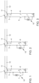
- a pre-charging principle is shown in a first embodiment.
- a first overhead line 11 and a second overhead line 12 are shown, with the overhead line 11 carrying a positive high-voltage and the overhead line 12 carrying a negative high-voltage.
- An intermediate circuit capacitor C is also shown, which is located, for example, at the input of an inverter (not shown).
- Current collectors 1, 2 are also shown, by means of which the overhead lines 11, 12 can be connected to voltage lines 3, 4.
- a switching element 5, 6, which is preferably designed as a relay, is arranged between the current collectors 1, 2 and the intermediate circuit capacitor C.
- a series connection of a resistor R and a third switching element 7 is also shown, which are parallel to the first switching element 5.
- the basic principle is as follows.
- FIG. 2 A second, alternative pre-charging principle is shown, in which the resistor R is arranged parallel to the first switching element 5.
- the second Switching element 6 is closed, whereby the first switching element 5 initially remains open.
- the pre-charge then runs again via the resistor R. Once the pre-charge process is complete, the first switching element 5 is closed and the resistor R is bridged.
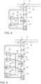
- a third pre-charging principle is shown, whereby the parallel circuit of resistor and third switching element 7 is arranged between the first switching element 5 and the intermediate circuit capacitor C.
- the two switching elements 5, 6 are then closed (one after the other or together), whereby the third switching element 7 remains open so that the pre-charging takes place via the resistor R.
- the resistor R is bridged by closing the third switching element 7.
- FIG.4 A pre-charging circuit 10 is now shown in a first embodiment, wherein the pre-charging circuit 10 of the pre-charging principle according to Fig.2
- a first voltage measuring device 13 is arranged between the high-voltage lines 3, 4 and detects a voltage U 1 between the current collectors 1, 2.
- a second voltage measuring device 14 is arranged parallel to the intermediate circuit capacitor C and detects the voltage U 2 on the intermediate circuit capacitor C.
- the pre-charging circuit 10 also has a control unit 15 which has a first voltage comparator 16 and a second voltage comparator 17 as well as a flip-flop 18.
- the first voltage comparator 16 compares the voltage U 1 with a first threshold voltage Ux, with a logical 1 being generated at the output when U 1 ⁇ Ux, with the output of the voltage comparator 16 being connected to the reset input of the flip-flop 18. Accordingly, the second voltage comparator 17 compares the voltage U 2 with a second threshold voltage U Y , whereby if U 2 > U Y a logical 1 is present at the output, which is connected to a set input of the flip-flop 18. It should be noted that the inputs of the voltage comparators 16, 17 are preferably not connected directly to the high-voltage lines 3, 4, but receive their input signal from the voltage measuring devices 13, 14.
- the pre-charging circuit 10 is immediately activated, i.e. the bridging of the resistor R is removed. If contact is then made again, the pre-charging circuit 10 is active and the resistor R limits the charging current of the intermediate circuit capacitor C.
- the advantage is that the switching unit 15 does not require any software and only needs the two local voltages U 1 , U 2 , so that the switching process is very fast.
- the switching state of the first switching element 5 can also be fed to a drive train control.
- Fig.5 a second embodiment is shown, wherein the pre-charging circuit 10 has two further resistors R, two further voltage comparators 19, 20, two further switching elements 21, 22 and two further flip-flops 23, 24.
- the basic principle is analogous Fig.4 , i.e. as long as U 1 ⁇ Ux, the switching elements 5, 21, 22 are open and the resistors R are active. If the intermediate circuit capacitor C is then slowly charged, U 2 rises. At U 2 > U Y3 the switching element 22 is then closed and bridges the lowest resistor R.
- the pre-charging circuits 10 are in Fig. 4 and Fig. 5 based on the pre-charging principle according to Fig. 2 explained, but can also be used with pre-loading principles according to Fig. 1 or Fig. 3 implement.
Landscapes
- Engineering & Computer Science (AREA)
- Power Engineering (AREA)
- Life Sciences & Earth Sciences (AREA)
- Sustainable Development (AREA)
- Sustainable Energy (AREA)
- Transportation (AREA)
- Mechanical Engineering (AREA)
- Electric Propulsion And Braking For Vehicles (AREA)
Description
- Die Erfindung betrifft eine Vorladeschaltung für einen Zwischenkreiskondensator eines elektrischen Antriebssystems mit einer Spannungsversorgung aus Oberleitungen, insbesondere für ein straßengeführtes Kraftfahrzeug sowie ein straßengeführtes Kraftfahrzeug.
- Es ist bekannt, schienen- oder straßengeführten Kraftfahrzeugen elektrische Energie aus spannungsführenden Oberleitungen zuzuführen. Dabei werden Stromabnehmer (Pantographen) an die Oberleitungen angebügelt oder abgebügelt. Die elektrischen Antriebssysteme weisen typischerweise einen Wechselrichter auf, der dann eine Elektromaschine bestromt, wobei am Eingang des Wechselrichters ein Zwischenkreiskondensator angeordnet ist. Der Zwischenkreiskondensator kann auch aus mehreren Kondensatoren bestehen, die parallel und/oder in Reihe geschaltet sind. Nachfolgend wird jedoch immer nur von einem resultierenden Zwischenkreiskondensator ausgegangen.
- Ist der Zwischenkreiskondensator entladen, kommt es beim Anbügeln zu großen Strömen, die mit parasitären Induktivitäten Überspannungen erzeugen können. Daher sind Vorladeschaltungen bekannt, die zu Beginn den Stromfluss begrenzen. Dazu wird beispielsweise ein Widerstand zugeschaltet. Eine solche Vorladeschaltung ist beispielsweise in der
EP 2 644 436 A1 als Stand der Technik dargestellt. Ist dann der Zwischenkreiskondensator ausreichend geladen, wird der Widerstand wieder abgeschaltet. Die Steuerung des Vorladewiderstandes erfolgt dabei zentral in einem Steuergerät, das den An- bzw. Abbügelungsvorgang steuert. Kommt es zu einem Abriss vom Stromabnehmer zur Oberleitung, kann dies zu Lichtbögen führen, sodass in solchen Fällen der Stromabnehmer abgebügelt wird. - Der Erfindung liegt das technische Problem zugrunde, eine Vorladeschaltung für einen Zwischenkreiskondensator zu verbessern sowie ein verbessertes straßengeführtes Kraftfahrzeug zu schaffen.
- Die Lösung des technischen Problems ergibt sich durch einen Vorladeschaltung mit den Merkmalen des Anspruchs 1 sowie ein straßengeführtes Kraftfahrzeug mit den Merkmalen des Anspruchs 9. Weitere vorteilhafte Ausgestaltungen der Erfindung ergeben sich aus den Unteransprüchen.
- Hierzu weist die Vorladeschaltung für einen Zwischenkreiskondensator eines elektrischen Antriebssystems mit einer Spannungsversorgung aus Oberleitungen mindestens einen Widerstand, mindestens zwei Schaltelemente sowie zwei Spannungsmesseinrichtungen auf. Dabei ist die erste Spannungsmesseinrichtung zwischen den Schaltelementen und Stromabnehmern für die Oberleitungen angeordnet und die zweite Spannungsmesseinrichtung parallel zum Zwischenkreiskondensator angeordnet. Durch mindestens ein Schaltelement ist der Widerstand zuschaltbar oder überbrückbar, wobei dem Schaltelement mindestens eine Steuereinheit zugeordnet ist. Das dem Widerstand zugeordnete Schaltelement kann eines der beiden Schaltelemente sein oder aber ein separates Schaltelement, was später noch näher erläutert wird. Dabei ist die Steuereinheit derart ausgebildet, dass automatisch der Widerstand zugeschaltet oder dessen Überbrückung abgeschaltet wird, wenn die Spannung der ersten Spannungsmesseinrichtung unter einem ersten Schwellwert liegt. Die Steuereinheit kann somit aus der zentralen Steuerung für den An- bzw. Abbügelungsvorgang herausgezogen werden und lokal dem Schaltelement zugeordnet werden, sodass der Schaltvorgang beschleunigt wird. Somit kann insbesondere auf kurzzeitige Abrisse der Kontaktierung schneller reagiert werden, bei der die zentrale Steuerung zu langsam ist. Insbesondere bei straßengeführten Kraftfahrzeugen kann es aufgrund von Straßenunebenheiten zu sehr kurzzeitigen Abrissen kommen. Dabei wird während des Abrisses der Zwischenkreiskondensator schnell durch die Elektromaschine entladen. Kommt es dann wieder zum Kontakt mit den Oberleitungen, fließen entsprechend hohe Ströme. Dies wird nun schnell und wirksam unterbunden, da auf ein Absinken der Spannung an der ersten Spannungsmesseinrichtung sofort die Vorladeschaltung aktiviert wird. Entsprechend kann dann die Vorladeschaltung auch wieder automatisch deaktiviert werden, wenn die Aufladung des Zwischenkreiskondensators erfolgt ist. Dabei ist die Steuereinheit als Hardware-Logik ausgebildet, sodass das Steuersignal sehr schnell erzeugt wird. Dabei kann die Hardware-Logik als FPGA oder als Operationsverstärker ausgebildet sein. Vorzugsweise weist die Hardware-Logik eine Hysterese-Funktionalität auf, um ein zu häufiges Ein- und Ausschalten der Vorladeschaltung zu verhindern.
- In einer Ausführungsform weist die Vorladeschaltung genau zwei Schaltelemente auf, wobei der mindestens eine Widerstand parallel zu einem Schaltelement angeordnet ist. Diese Schaltung benötigt wenig Bauteile. Allerdings besteht eine dauerhafte galvanische Verbindung zwischen Stromabnehmer und Zwischenkreiskondensator.
- In einer alternativen Ausführungsform ist parallel zu dem Widerstand ein drittes Schaltelement angeordnet, mittels dessen der Widerstand überbrückbar ist. Der Vorteil ist, dass so eine galvanische Trennung realisierbar ist.
- Die Schaltelemente können dabei als Relais oder als Halbleiterschalter (z.B. IGBT oder MOSFET) ausgebildet sein. Der Vorteil von Relais ist die galvanische Trennung, wobei der Vorteil der Halbleiterschalter die schnellere Schaltzeit ist.
- In einer weiteren Ausführungsform sind das erste und zweite Schaltelement als Relais ausgebildet und das dritte Schaltelement als Halbleiterschalter ausgebildet. Somit wird einerseits die galvanische Trennung realisiert, wobei die Zuschaltung des Widerstandes durch den schnellen Halbleiterschalter erfolgt.
- In einer weiteren Ausführungsform weist die Steuereinheit zwei Spannungskomparatoren und ein Flip-Flop auf. Der erste Spannungskomparator vergleicht die Spannung der ersten Messeinrichtung mit einer ersten Schwellenspannung und der zweite Spannungskomparator vergleicht die Spannung der zweiten Spannungsmesseinrichtung mit einer zweiten Schwellenspannung. Dabei wird der Ausgang des ersten Spannungskomparators auf einem Reset-Eingang des Flip-Flops gelegt und der Ausgang des zweiten Spannungskomparators auf einen Set-Eingang gelegt. Somit ist sichergestellt, dass, solange die Spannung der ersten Spannungsmesseinrichtung kleiner als die erste Schwellenspannung ist, die Vorladeschaltung aktiv ist. Ist dann die Spannung der ersten Spannungsmesseinrichtung größer als die erste Schwellenspannung die die Spannung der zweiten Spannungsmesseinrichtung größer als die zweite Schwellenspannung, so wird die Vorladeschaltung deaktiviert.
- In einer weiteren Ausführungsform weist die Vorladeschaltung mindestens zwei Widerstände auf, wobei dem mindestens zweiten Widerstand ein zusätzliches Schaltelement zugeordnet ist, wobei die Steuereinheit derart ausgebildet ist, in Abhängigkeit der Spannung der zweiten Spannungsmesseinrichtung oder einer Strommesseinrichtung die Widerstände sukzessive abzuschalten oder zu überbrücken. Hierdurch kann der Vorladevorgang beschleunigt werden.
- Ein bevorzugtes Anwendungsgebiet ist der Einsatz in einem straßengeführten Kraftfahrzeug.
- Die Erfindung wird nachfolgend anhand bevorzugter Ausführungsformen näher erläutert. Die Figuren zeigen:
- Fig. 1
- eine schematische Darstellung eines Vorladeprinzips in einer ersten Ausführungsform,
- Fig. 2
- eine schematische Darstellung eines Vorladeprinzips in einer zweiten Ausführungsform,
- Fig. 3
- eine schematische Darstellung eines Vorladeprinzips in einer dritten Ausführungsform,
- Fig. 4
- eine schematische Darstellung einer Vorladeschaltung in einer ersten Ausführungsform und
- Fig. 5
- eine schematische Darstellung einer Vorladeschaltung in einer zweiten Ausführungsform.
- In der
Fig. 1 ist ein Vorladeprinzip in einer ersten Ausführungsform dargestellt. Dabei sind eine erste Oberleitung 11 und eine zweite Oberleitung 12 dargestellt, wobei die Oberleitung 11 eine positive Hochvoltspannung und die Oberleitung 12 eine negative Hochvoltspannung führt. Weiter ist ein Zwischenkreiskondensator C dargestellt, der beispielsweise am Eingang eines nicht dargestellten Wechselrichters liegt. Weiter sind Stromabnehmer 1, 2 dargestellt, mittels derer die Oberleitungen 11, 12 mit Spannungsleitungen 3, 4 verbindbar sind. Zwischen den Stromabnehmern 1, 2 und dem Zwischenkreiskondensator C ist jeweils ein Schaltelement 5, 6 angeordnet, die vorzugsweise als Relais ausgebildet sind. Weiter ist eine Reihenschaltung aus einem Widerstand R und einem dritten Schaltelement 7 dargestellt, die parallel zu dem ersten Schaltelement 5 liegen. Das Grundprinzip ist nun wie folgt. Im Ausgangszustand sind alle Schaltelemente offen. Zuerst wird das dritte Schaltelement 7 geschlossen und anschließend das zweite Schaltelement 6 geschlossen. Der Widerstand R wurde also zugeschaltet und reduziert den Ladestrom für den Zwischenkreiskondensator C. Ist dieser ausreichend vorgeladen, wird das Schaltelement 5 geschlossen und das Schaltelement 7 anschließend geöffnet, was aber nicht zwingend ist. - In der
Fig. 2 ist ein zweites, alternatives Vorladeprinzip dargestellt, wobei der Widerstand R parallel zum ersten Schaltelement 5 angeordnet wird. Zum Vorladen wird das zweite Schaltelement 6 geschlossen, wobei das erste Schaltelement 5 zunächst offen bleibt. Die Vorladung läuft dann wieder über den Widerstand R. Ist der Vorladevorgang abgeschlossen, wird das erste Schaltelement 5 geschlossen und der Widerstand R überbrückt. - In der
Fig. 3 ist schließlich ein drittes Vorladeprinzip dargestellt, wobei die Parallelschaltung aus Widerstand und drittem Schaltelement 7 zwischen dem ersten Schaltelement 5 und dem Zwischenkreiskondensator C angeordnet ist. Zum Vorladen werden dann die beiden Schaltelemente 5, 6 geschlossen (nacheinander oder zusammen), wobei das dritte Schaltelement 7 offen bleibt, sodass die Vorladung über den Widerstand R erfolgt. Ist die Vorladung abgeschlossen, so wird durch Schließen des dritten Schaltelements 7 der Widerstand R überbrückt. - In der
Fig. 4 ist nun eine Vorladeschaltung 10 in einer ersten Ausführungsform dargestellt, wobei sich die Vorladeschaltung 10 des Vorladeprinzips gemäßFig. 2 bedient. Dabei ist eine erste Spannungsmesseinrichtung 13 zwischen den Hochvoltleitungen 3, 4 angeordnet und erfasst eine Spannung U1 zwischen den Stromabnehmern 1, 2. Eine zweite Spannungsmesseinrichtung 14 ist parallel zum Zwischenkreiskondensator C angeordnet und erfasst die Spannung U2 am Zwischenkreiskondensator C. Weiter weist die Vorladeschaltung 10 eine Steuereinheit 15 auf, die einen ersten Spannungskomparator 16 und einen zweiten Spannungskomparator 17 sowie ein Flip-Flop 18 aufweist. Der erste Spannungskomparator 16 vergleicht die Spannung U1 mit einer ersten Schwellenspannung Ux, wobei bei U1 < Ux eine logische 1 am Ausgang erzeugt wird, wobei der Ausgang des Spannungskomparators 16 mit dem Reset-Eingang des Flip-Flops 18 verbunden ist. Entsprechend vergleicht der zweite Spannungskomparator 17 die Spannung U2 mit einer zweiten Schwellenspannung UY, wobei bei U2 > UY eine logische 1 am Ausgang anliegt, der mit einem Set-Eingang des Flip-Flops 18 verbunden ist. Dabei sei angemerkt, dass die Eingänge der Spannungskomparatoren 16, 17 vorzugsweise nicht direkt mit den Hochvoltleitungen 3, 4 verbunden sind, sondern ihr Eingangssignal von den Spannungsmesseinrichtungen 13, 14 erhalten. Die Wirkungsweise der Steuereinheit 15 ist nun wie folgt:
Solange die Bedingung U1 < Ux (R=1) erfüllt ist, liegt am Q-Ausgang des Flip-Flops 18 eine 0 an, sodass das erste Schaltelement 5 offen ist und den Widerstand R nicht überbrückt. Nur wenn U1 > UX und gleichzeitig U2 > UY ist (S=1, R=0), wird das erste Schaltelement 5 geschlossen und überbrückt den Widerstand R. - Hierdurch wird bewirkt, dass, wenn es zu einem Spannungseinbruch aufgrund eines Kontaktabrisses zwischen Stromabnehmer 1, 2 und Oberleitungen 11, 12 kommt, sofort die Vorladeschaltung 10 aktiv geschaltet wird, also die Überbrückung von dem Widerstand R aufgehoben wird. Kommt es dann wieder zum Kontakt, so ist die Vorladeschaltung 10 aktiv und der Widerstand R begrenzt den Ladestrom des Zwischenkreiskondensators C. Der Vorteil ist, dass die Schalteinheit 15 keinerlei Software benötigt und nur die beiden lokalen Spannungen U1, U2 benötigt, sodass der Schaltvorgang sehr schnell ist. Der Schaltzustand des ersten Schaltelements 5 kann dabei zusätzlich einer Antriebsstrangsteuerung zugeführt werden.
- In der
Fig. 5 ist eine zweite Ausführungsform dargestellt, wobei die Vorladeschaltung 10 zwei weitere Widerstände R, zwei weitere Spannungskomparatoren 19, 20, zwei weitere Schaltelemente 21, 22 sowie zwei weitere Flip-Flops 23, 24 aufweist. Das Grundprinzip ist analogFig. 4 , d.h. solange U1 < Ux ist, sind die Schaltelemente 5, 21, 22 offen und die Widerstände R aktiv. Wird dann der Zwischenkreiskondensator C langsam aufgeladen, so steigt U2. Bei U2 > UY3 wird dann das Schaltelement 22 geschlossen und überbrückt den untersten Widerstand R. Steigt dann die Spannung U2 weiter an, so wird bei U2 > UY2 das Schaltelement 21 geschlossen und schließlich bei U2 > UY1 das erste Schaltelement 5 geschlossen, wobei gilt: UY1 > UY2 > UY3. Bei UY3 > UY2 > UY1 dreht sich entsprechend die Reihenfolge des Schließens der Schaltelemente 5, 21, 22 um. - Die Vorladeschaltungen 10 sind in
Fig. 4 und Fig. 5 anhand des Vorladeprinzips gemäßFig. 2 erläutert, lassen sich aber auch mit Vorladeprinzipien gemäßFig. 1 oder Fig. 3 umsetzen. -
- 1
- Stromabnehmer
- 2
- Stromabnehmer
- 3
- Spannungsleitung
- 4
- Spannungsleitung
- 5
- Schaltelement
- 6
- Schaltelement
- 7
- Schaltelement
- 10
- Vorladeschaltung
- 11
- Oberleitung
- 12
- Oberleitung
- 13
- Spannungsmesseinrichtung
- 14
- Spannungsmesseinrichtung
- 15
- Steuereinheit
- 16
- Spannungskomparator
- 17
- Spannungskomparator
- 18
- Flip-Flop
- 19
- Spannungskomparator
- 20
- Spannungskomparator
- 21
- Schaltelement
- 22
- Schaltelement
- 23
- Flip-Flop
- 24
- Flip-Flop
- R
- Widerstand
- C
- Zwischenkreiskondensator
Claims (9)
- Vorladeschaltung (10) für einen Zwischenkreiskondensator (C) eines elektrischen Antriebssystems mit einer Spannungsversorgung aus Oberleitungen (11, 12), wobei die Vorladeschaltung (10) mindestens einen Widerstand (R), mindestens zwei Schaltelemente (5, 6) sowie zwei Spannungsmesseinrichtungen (13, 14) aufweist, wobei die erste Spannungsmesseinrichtung (13) zwischen den Schaltelementen (5, 6) und Stromabnehmern (1, 2) für die Oberleitungen (11, 12) angeordnet ist und die zweite Spannungsmesseinrichtung (14) parallel zum Zwischenkreiskondensator (C) angeordnet ist, wobei durch mindestens ein Schaltelement (5, 7, 21, 22) der Widerstand (R) zuschaltbar oder überbrückbar ist, wobei dem Schaltelement (5, 7, 21, 22) mindestens eine Steuereinheit (15) zugeordnet ist,
dadurch gekennzeichnet, dass
die Steuereinheit (15) lokal dem Schaltelement (5, 7, 21, 22) zugeordnet ist und als Hardware-Logik ohne Software ausgebildet ist, die als Eingangsgrößen nur die beiden Spannungen (U1, U2) der zwei Spannungsmesseinrichtungen (13, 14) erhält, wobei die Steuereinheit (15) derart ausgebildet ist, dass automatisch der mindestens eine Widerstand (R) zugeschaltet oder dessen Überbrückung abgeschaltet wird, wenn die Spannung (U1) der ersten Spannungsmesseinrichtung (13) unter einem ersten Schwellwert (Ux) liegt, wobei automatisch der mindestens eine Widerstand (R) abgeschaltet oder dessen Überbrückung zugeschaltet wird, wenn die Spannung (U1) der ersten Spannungsmesseinrichtung (13) über dem ersten Schwellwert (Ux) und die Spannung (U2) der zweiten Spannungsmesseinrichtung (14) über einem zweiten Schwellwert (UY) liegt. - Vorladeschaltung nach Anspruch 1, dadurch gekennzeichnet, dass die Vorladeschaltung (10) genau zwei Schaltelemente (5, 6) aufweist, wobei der mindestens eine Widerstand (R) parallel zu einem Schaltelement (5) angeordnet ist.
- Vorladeschaltung nach Anspruch 1, dadurch gekennzeichnet, dass parallel zu dem Widerstand (R) ein drittes Schaltelement (7) angeordnet ist.
- Vorladeschaltung nach einem der vorangegangenen Ansprüche, dadurch gekennzeichnet, dass die Schaltelemente (5, 6, 7, 21, 22) als Relais ausgebildet sind.
- Vorladeschaltung nach einem der vorangegangenen Ansprüche, dadurch gekennzeichnet, dass die Schaltelemente (5, 6, 7, 21, 22) als Halbleiterschaltelemente ausgebildet sind.
- Vorladeschaltung nach Anspruch 3, dadurch gekennzeichnet, dass das erste und zweite Schaltelement (5, 6) als Relais ausgebildet sind und das dritte Schaltelement (7) als Halbleiterschalter ausgebildet ist.
- Vorladeschaltung nach einem der vorangegangenen Ansprüche, dadurch gekennzeichnet, dass die Steuereinheit (15) aus mindestens zwei Spannungskomparatoren (16, 17) und mindestens einem Flip-Flop (18) besteht.
- Vorladeschaltung nach einem der vorangegangenen Ansprüche, dadurch gekennzeichnet, dass die Vorladeschaltung (10) mindestens zwei Widerstände (R) aufweist, wobei dem mindestens zweiten Widerstand (R) ein zusätzliches Schaltelement (21, 22) zugeordnet ist, wobei die Steuereinheit (15) derart ausgebildet ist, in Abhängigkeit der Spannung (U2) der zweiten Spannungsmesseinrichtung (14) oder einer Strommesseinrichtung die Widerstände (R) sukzessive abzuschalten oder zu überbrücken.
- Straßengeführtes Kraftfahrzeug, dadurch gekennzeichnet, dass das Kraftfahrzeug eine Vorladeschaltung (10) nach einem der Ansprüche 1 bis 8 aufweist.
Applications Claiming Priority (1)
| Application Number | Priority Date | Filing Date | Title |
|---|---|---|---|
| DE102020200990.2A DE102020200990A1 (de) | 2020-01-28 | 2020-01-28 | Vorladeschaltung und straßengeführtes Kraftfahrzeug |
Publications (2)
| Publication Number | Publication Date |
|---|---|
| EP3858656A1 EP3858656A1 (de) | 2021-08-04 |
| EP3858656B1 true EP3858656B1 (de) | 2024-07-31 |
Family
ID=73856042
Family Applications (1)
| Application Number | Title | Priority Date | Filing Date |
|---|---|---|---|
| EP20215857.2A Active EP3858656B1 (de) | 2020-01-28 | 2020-12-21 | Vorladeschaltung und strassengeführtes kraftfahrzeug |
Country Status (3)
| Country | Link |
|---|---|
| EP (1) | EP3858656B1 (de) |
| CN (1) | CN113193741B (de) |
| DE (1) | DE102020200990A1 (de) |
Family Cites Families (12)
| Publication number | Priority date | Publication date | Assignee | Title |
|---|---|---|---|---|
| JP4362962B2 (ja) * | 2000-09-27 | 2009-11-11 | 富士電機システムズ株式会社 | コンデンサの良否判定装置 |
| JP2007202250A (ja) | 2006-01-25 | 2007-08-09 | Toyo Electric Mfg Co Ltd | 電気車制御装置 |
| JP5231892B2 (ja) * | 2008-08-04 | 2013-07-10 | 株式会社東芝 | 電気車用電源装置 |
| JP2012165598A (ja) * | 2011-02-08 | 2012-08-30 | Toshiba Corp | 電気車用電源装置及び電気車用電源装置のコンデンサ容量算出方法 |
| US9042146B2 (en) * | 2011-11-14 | 2015-05-26 | Rockwell Automation Technologies, Inc. | DC pre-charge circuit |
| WO2013102960A1 (ja) * | 2012-01-05 | 2013-07-11 | 株式会社 東芝 | 電気車制御装置及び電気車 |
| EP2644436B1 (de) | 2012-03-27 | 2018-05-30 | ALSTOM Transport Technologies | Verbessertes starkes Vorladen für Parallelwandler |
| DE112012006781B4 (de) | 2012-08-06 | 2022-06-30 | Mitsubishi Electric Corporation | Energieumsetzervorrichtung |
| DE102013008586A1 (de) * | 2013-05-17 | 2014-11-20 | Audi Ag | Vorladen eines Kraftfahrzeug-Hochvoltnetzes |
| JP2017153279A (ja) * | 2016-02-25 | 2017-08-31 | 株式会社東芝 | 電気車制御装置および電気車システム |
| DE102016211756A1 (de) * | 2016-06-29 | 2018-01-04 | Bayerische Motoren Werke Aktiengesellschaft | Vorladeschaltung für einen elektrischen Turbolader |
| JP6474455B2 (ja) * | 2017-05-01 | 2019-02-27 | ファナック株式会社 | Dcリンクコンデンサの初期充電時間を最適化するコンバータ装置 |
-
2020
- 2020-01-28 DE DE102020200990.2A patent/DE102020200990A1/de not_active Ceased
- 2020-12-21 EP EP20215857.2A patent/EP3858656B1/de active Active
-
2021
- 2021-01-26 CN CN202110102253.XA patent/CN113193741B/zh active Active
Also Published As
| Publication number | Publication date |
|---|---|
| DE102020200990A1 (de) | 2021-07-29 |
| EP3858656A1 (de) | 2021-08-04 |
| CN113193741B (zh) | 2024-07-02 |
| CN113193741A (zh) | 2021-07-30 |
Similar Documents
| Publication | Publication Date | Title |
|---|---|---|
| EP2980659B1 (de) | Vorrichtung und Verfahren zum Überwachen und Schalten eines Lastkreises | |
| DE10014243B4 (de) | Zwei-Batteriensystem | |
| DE102010007452A1 (de) | Schaltentlastung für einen Trennschalter | |
| WO2018041452A1 (de) | Trennvorrichtung | |
| EP3699015A1 (de) | Elektrische schaltungsvorrichtung zur erkennung eines nichtgeöffneten schaltkontaktes sowie einer schutzleiterunterbrechung in einer ein- oder mehrphasigen elektrischen zuleitung | |
| EP3915127B1 (de) | Gleichstrom-schutzschaltgerät | |
| DE102016112764A1 (de) | Schnittstellenmodul für ein bordnetz eines kraftfahrzeugs, stromverteiler sowie bordnetz für ein kraftfahrzeug | |
| DE102020206478A1 (de) | Steuervorrichtung für einen Stromrichter, elektrisches Antriebssystem und Verfahren zum Einstellen eines sicheren Betriebszustandes | |
| DE10330284A1 (de) | Überspannungsbegrenzer für einen Traktionsstromrichter | |
| DE102013017091A1 (de) | Energiespeichereinrichtung für einen Kraftwagen | |
| DE10221081A1 (de) | Wechselrichter für eine elektrische Maschine | |
| EP3858656B1 (de) | Vorladeschaltung und strassengeführtes kraftfahrzeug | |
| DE102018216125A1 (de) | Verfahren zum Trennen einer Batterie | |
| DE60017311T2 (de) | Verfahren zur Überwachung der Endstellung eines mobilen Elements und Vorrichtung zur Durchführung des Verfahrens | |
| DE102018214772A1 (de) | Verfahren zum Betreiben wenigstens einer elektrischen Komponente eines Fahrzeugs | |
| DE102018202590A1 (de) | Schaltvorrichtung für ein Hochvolt-Bordnetz eines Kraftfahrzeugs, ein Kraftfahrzeug mit einem Hochvolt-Bordnetz sowie ein Steuerverfahren für ein Hochvolt-Bordnetz eines Kraftfahrzeugs | |
| DE102018218784A1 (de) | Zentraler Traktionsnetzverteiler und Traktionsnetz | |
| WO2024017776A1 (de) | Fahrzeug mit einem elektrischen bordnetz | |
| DE102018203363A1 (de) | Fahrzeuggeräteschaltung mit Halbleiter-Schaltelementen für Hochvoltspannung sowie Kraftfahrzeug und Betriebsverfahren | |
| DE102019207456A1 (de) | Ladeschaltung und Verfahren zum Betrieb einer solchen | |
| DE102014008906A1 (de) | Elektronisches Relais | |
| DE102019203515A1 (de) | Verfahren zur Energieversorgung von Verbrauchern eines Bordnetzes für ein Fahrzeug sowie ein Bordnetz für ein Fahrzeug | |
| DE19733019C2 (de) | Elektrische Schaltungsanordnung | |
| EP3776837B1 (de) | Energiewandler | |
| DE102014016018B4 (de) | Schalteinrichtung für ein Bordnetz eines Kraftfahrzeugs, Bordnetz und Kraftfahrzeug |
Legal Events
| Date | Code | Title | Description |
|---|---|---|---|
| PUAI | Public reference made under article 153(3) epc to a published international application that has entered the european phase |
Free format text: ORIGINAL CODE: 0009012 |
|
| STAA | Information on the status of an ep patent application or granted ep patent |
Free format text: STATUS: THE APPLICATION HAS BEEN PUBLISHED |
|
| AK | Designated contracting states |
Kind code of ref document: A1 Designated state(s): AL AT BE BG CH CY CZ DE DK EE ES FI FR GB GR HR HU IE IS IT LI LT LU LV MC MK MT NL NO PL PT RO RS SE SI SK SM TR |
|
| STAA | Information on the status of an ep patent application or granted ep patent |
Free format text: STATUS: REQUEST FOR EXAMINATION WAS MADE |
|
| 17P | Request for examination filed |
Effective date: 20220204 |
|
| RBV | Designated contracting states (corrected) |
Designated state(s): AL AT BE BG CH CY CZ DE DK EE ES FI FR GB GR HR HU IE IS IT LI LT LU LV MC MK MT NL NO PL PT RO RS SE SI SK SM TR |
|
| STAA | Information on the status of an ep patent application or granted ep patent |
Free format text: STATUS: EXAMINATION IS IN PROGRESS |
|
| 17Q | First examination report despatched |
Effective date: 20220822 |
|
| GRAP | Despatch of communication of intention to grant a patent |
Free format text: ORIGINAL CODE: EPIDOSNIGR1 |
|
| STAA | Information on the status of an ep patent application or granted ep patent |
Free format text: STATUS: GRANT OF PATENT IS INTENDED |
|
| INTG | Intention to grant announced |
Effective date: 20240315 |
|
| GRAS | Grant fee paid |
Free format text: ORIGINAL CODE: EPIDOSNIGR3 |
|
| GRAA | (expected) grant |
Free format text: ORIGINAL CODE: 0009210 |
|
| STAA | Information on the status of an ep patent application or granted ep patent |
Free format text: STATUS: THE PATENT HAS BEEN GRANTED |
|
| P01 | Opt-out of the competence of the unified patent court (upc) registered |
Effective date: 20240527 |
|
| AK | Designated contracting states |
Kind code of ref document: B1 Designated state(s): AL AT BE BG CH CY CZ DE DK EE ES FI FR GB GR HR HU IE IS IT LI LT LU LV MC MK MT NL NO PL PT RO RS SE SI SK SM TR |
|
| REG | Reference to a national code |
Ref country code: CH Ref legal event code: EP Ref country code: GB Ref legal event code: FG4D Free format text: NOT ENGLISH |
|
| REG | Reference to a national code |
Ref country code: DE Ref legal event code: R096 Ref document number: 502020008725 Country of ref document: DE |
|
| REG | Reference to a national code |
Ref country code: IE Ref legal event code: FG4D Free format text: LANGUAGE OF EP DOCUMENT: GERMAN |
|
| REG | Reference to a national code |
Ref country code: LT Ref legal event code: MG9D |
|
| REG | Reference to a national code |
Ref country code: NL Ref legal event code: MP Effective date: 20240731 |
|
| PG25 | Lapsed in a contracting state [announced via postgrant information from national office to epo] |
Ref country code: PT Free format text: LAPSE BECAUSE OF FAILURE TO SUBMIT A TRANSLATION OF THE DESCRIPTION OR TO PAY THE FEE WITHIN THE PRESCRIBED TIME-LIMIT Effective date: 20241202 |
|
| PG25 | Lapsed in a contracting state [announced via postgrant information from national office to epo] |
Ref country code: PT Free format text: LAPSE BECAUSE OF FAILURE TO SUBMIT A TRANSLATION OF THE DESCRIPTION OR TO PAY THE FEE WITHIN THE PRESCRIBED TIME-LIMIT Effective date: 20241202 |
|
| PGFP | Annual fee paid to national office [announced via postgrant information from national office to epo] |
Ref country code: DE Payment date: 20241231 Year of fee payment: 5 |
|
| PG25 | Lapsed in a contracting state [announced via postgrant information from national office to epo] |
Ref country code: NO Free format text: LAPSE BECAUSE OF FAILURE TO SUBMIT A TRANSLATION OF THE DESCRIPTION OR TO PAY THE FEE WITHIN THE PRESCRIBED TIME-LIMIT Effective date: 20241031 |
|
| PG25 | Lapsed in a contracting state [announced via postgrant information from national office to epo] |
Ref country code: NL Free format text: LAPSE BECAUSE OF FAILURE TO SUBMIT A TRANSLATION OF THE DESCRIPTION OR TO PAY THE FEE WITHIN THE PRESCRIBED TIME-LIMIT Effective date: 20240731 Ref country code: GR Free format text: LAPSE BECAUSE OF FAILURE TO SUBMIT A TRANSLATION OF THE DESCRIPTION OR TO PAY THE FEE WITHIN THE PRESCRIBED TIME-LIMIT Effective date: 20241101 Ref country code: PL Free format text: LAPSE BECAUSE OF FAILURE TO SUBMIT A TRANSLATION OF THE DESCRIPTION OR TO PAY THE FEE WITHIN THE PRESCRIBED TIME-LIMIT Effective date: 20240731 Ref country code: FI Free format text: LAPSE BECAUSE OF FAILURE TO SUBMIT A TRANSLATION OF THE DESCRIPTION OR TO PAY THE FEE WITHIN THE PRESCRIBED TIME-LIMIT Effective date: 20240731 |
|
| PGFP | Annual fee paid to national office [announced via postgrant information from national office to epo] |
Ref country code: GB Payment date: 20241217 Year of fee payment: 5 |
|
| PG25 | Lapsed in a contracting state [announced via postgrant information from national office to epo] |
Ref country code: BG Free format text: LAPSE BECAUSE OF FAILURE TO SUBMIT A TRANSLATION OF THE DESCRIPTION OR TO PAY THE FEE WITHIN THE PRESCRIBED TIME-LIMIT Effective date: 20240731 |
|
| PGFP | Annual fee paid to national office [announced via postgrant information from national office to epo] |
Ref country code: FR Payment date: 20241227 Year of fee payment: 5 |
|
| PG25 | Lapsed in a contracting state [announced via postgrant information from national office to epo] |
Ref country code: LV Free format text: LAPSE BECAUSE OF FAILURE TO SUBMIT A TRANSLATION OF THE DESCRIPTION OR TO PAY THE FEE WITHIN THE PRESCRIBED TIME-LIMIT Effective date: 20240731 |
|
| PG25 | Lapsed in a contracting state [announced via postgrant information from national office to epo] |
Ref country code: IS Free format text: LAPSE BECAUSE OF FAILURE TO SUBMIT A TRANSLATION OF THE DESCRIPTION OR TO PAY THE FEE WITHIN THE PRESCRIBED TIME-LIMIT Effective date: 20241130 |
|
| PG25 | Lapsed in a contracting state [announced via postgrant information from national office to epo] |
Ref country code: HR Free format text: LAPSE BECAUSE OF FAILURE TO SUBMIT A TRANSLATION OF THE DESCRIPTION OR TO PAY THE FEE WITHIN THE PRESCRIBED TIME-LIMIT Effective date: 20240731 |
|
| PG25 | Lapsed in a contracting state [announced via postgrant information from national office to epo] |
Ref country code: RS Free format text: LAPSE BECAUSE OF FAILURE TO SUBMIT A TRANSLATION OF THE DESCRIPTION OR TO PAY THE FEE WITHIN THE PRESCRIBED TIME-LIMIT Effective date: 20241031 Ref country code: ES Free format text: LAPSE BECAUSE OF FAILURE TO SUBMIT A TRANSLATION OF THE DESCRIPTION OR TO PAY THE FEE WITHIN THE PRESCRIBED TIME-LIMIT Effective date: 20240731 |
|
| PG25 | Lapsed in a contracting state [announced via postgrant information from national office to epo] |
Ref country code: RS Free format text: LAPSE BECAUSE OF FAILURE TO SUBMIT A TRANSLATION OF THE DESCRIPTION OR TO PAY THE FEE WITHIN THE PRESCRIBED TIME-LIMIT Effective date: 20241031 Ref country code: PL Free format text: LAPSE BECAUSE OF FAILURE TO SUBMIT A TRANSLATION OF THE DESCRIPTION OR TO PAY THE FEE WITHIN THE PRESCRIBED TIME-LIMIT Effective date: 20240731 Ref country code: NO Free format text: LAPSE BECAUSE OF FAILURE TO SUBMIT A TRANSLATION OF THE DESCRIPTION OR TO PAY THE FEE WITHIN THE PRESCRIBED TIME-LIMIT Effective date: 20241031 Ref country code: NL Free format text: LAPSE BECAUSE OF FAILURE TO SUBMIT A TRANSLATION OF THE DESCRIPTION OR TO PAY THE FEE WITHIN THE PRESCRIBED TIME-LIMIT Effective date: 20240731 Ref country code: LV Free format text: LAPSE BECAUSE OF FAILURE TO SUBMIT A TRANSLATION OF THE DESCRIPTION OR TO PAY THE FEE WITHIN THE PRESCRIBED TIME-LIMIT Effective date: 20240731 Ref country code: IS Free format text: LAPSE BECAUSE OF FAILURE TO SUBMIT A TRANSLATION OF THE DESCRIPTION OR TO PAY THE FEE WITHIN THE PRESCRIBED TIME-LIMIT Effective date: 20241130 Ref country code: HR Free format text: LAPSE BECAUSE OF FAILURE TO SUBMIT A TRANSLATION OF THE DESCRIPTION OR TO PAY THE FEE WITHIN THE PRESCRIBED TIME-LIMIT Effective date: 20240731 Ref country code: GR Free format text: LAPSE BECAUSE OF FAILURE TO SUBMIT A TRANSLATION OF THE DESCRIPTION OR TO PAY THE FEE WITHIN THE PRESCRIBED TIME-LIMIT Effective date: 20241101 Ref country code: FI Free format text: LAPSE BECAUSE OF FAILURE TO SUBMIT A TRANSLATION OF THE DESCRIPTION OR TO PAY THE FEE WITHIN THE PRESCRIBED TIME-LIMIT Effective date: 20240731 Ref country code: ES Free format text: LAPSE BECAUSE OF FAILURE TO SUBMIT A TRANSLATION OF THE DESCRIPTION OR TO PAY THE FEE WITHIN THE PRESCRIBED TIME-LIMIT Effective date: 20240731 Ref country code: BG Free format text: LAPSE BECAUSE OF FAILURE TO SUBMIT A TRANSLATION OF THE DESCRIPTION OR TO PAY THE FEE WITHIN THE PRESCRIBED TIME-LIMIT Effective date: 20240731 |
|
| PG25 | Lapsed in a contracting state [announced via postgrant information from national office to epo] |
Ref country code: DK Free format text: LAPSE BECAUSE OF FAILURE TO SUBMIT A TRANSLATION OF THE DESCRIPTION OR TO PAY THE FEE WITHIN THE PRESCRIBED TIME-LIMIT Effective date: 20240731 Ref country code: RO Free format text: LAPSE BECAUSE OF FAILURE TO SUBMIT A TRANSLATION OF THE DESCRIPTION OR TO PAY THE FEE WITHIN THE PRESCRIBED TIME-LIMIT Effective date: 20240731 Ref country code: SM Free format text: LAPSE BECAUSE OF FAILURE TO SUBMIT A TRANSLATION OF THE DESCRIPTION OR TO PAY THE FEE WITHIN THE PRESCRIBED TIME-LIMIT Effective date: 20240731 |
|
| PG25 | Lapsed in a contracting state [announced via postgrant information from national office to epo] |
Ref country code: EE Free format text: LAPSE BECAUSE OF FAILURE TO SUBMIT A TRANSLATION OF THE DESCRIPTION OR TO PAY THE FEE WITHIN THE PRESCRIBED TIME-LIMIT Effective date: 20240731 |
|
| PG25 | Lapsed in a contracting state [announced via postgrant information from national office to epo] |
Ref country code: CZ Free format text: LAPSE BECAUSE OF FAILURE TO SUBMIT A TRANSLATION OF THE DESCRIPTION OR TO PAY THE FEE WITHIN THE PRESCRIBED TIME-LIMIT Effective date: 20240731 |
|
| PG25 | Lapsed in a contracting state [announced via postgrant information from national office to epo] |
Ref country code: IT Free format text: LAPSE BECAUSE OF FAILURE TO SUBMIT A TRANSLATION OF THE DESCRIPTION OR TO PAY THE FEE WITHIN THE PRESCRIBED TIME-LIMIT Effective date: 20240731 Ref country code: SK Free format text: LAPSE BECAUSE OF FAILURE TO SUBMIT A TRANSLATION OF THE DESCRIPTION OR TO PAY THE FEE WITHIN THE PRESCRIBED TIME-LIMIT Effective date: 20240731 |
|
| REG | Reference to a national code |
Ref country code: DE Ref legal event code: R097 Ref document number: 502020008725 Country of ref document: DE |
|
| PLBE | No opposition filed within time limit |
Free format text: ORIGINAL CODE: 0009261 |
|
| STAA | Information on the status of an ep patent application or granted ep patent |
Free format text: STATUS: NO OPPOSITION FILED WITHIN TIME LIMIT |
|
| PG25 | Lapsed in a contracting state [announced via postgrant information from national office to epo] |
Ref country code: MC Free format text: LAPSE BECAUSE OF FAILURE TO SUBMIT A TRANSLATION OF THE DESCRIPTION OR TO PAY THE FEE WITHIN THE PRESCRIBED TIME-LIMIT Effective date: 20240731 |
|
| 26N | No opposition filed |
Effective date: 20250501 |
|
| REG | Reference to a national code |
Ref country code: CH Ref legal event code: PL |
|
| PG25 | Lapsed in a contracting state [announced via postgrant information from national office to epo] |
Ref country code: LU Free format text: LAPSE BECAUSE OF NON-PAYMENT OF DUE FEES Effective date: 20241221 |
|
| PG25 | Lapsed in a contracting state [announced via postgrant information from national office to epo] |
Ref country code: SE Free format text: LAPSE BECAUSE OF FAILURE TO SUBMIT A TRANSLATION OF THE DESCRIPTION OR TO PAY THE FEE WITHIN THE PRESCRIBED TIME-LIMIT Effective date: 20240731 |
|
| REG | Reference to a national code |
Ref country code: BE Ref legal event code: MM Effective date: 20241231 |
|
| PG25 | Lapsed in a contracting state [announced via postgrant information from national office to epo] |
Ref country code: BE Free format text: LAPSE BECAUSE OF NON-PAYMENT OF DUE FEES Effective date: 20241231 |
|
| PG25 | Lapsed in a contracting state [announced via postgrant information from national office to epo] |
Ref country code: CH Free format text: LAPSE BECAUSE OF NON-PAYMENT OF DUE FEES Effective date: 20241231 |
|
| PG25 | Lapsed in a contracting state [announced via postgrant information from national office to epo] |
Ref country code: IE Free format text: LAPSE BECAUSE OF NON-PAYMENT OF DUE FEES Effective date: 20241221 |