EP3858655A1 - Maglev vehicle and suspension frame assembly thereof - Google Patents
Maglev vehicle and suspension frame assembly thereof Download PDFInfo
- Publication number
- EP3858655A1 EP3858655A1 EP18935863.3A EP18935863A EP3858655A1 EP 3858655 A1 EP3858655 A1 EP 3858655A1 EP 18935863 A EP18935863 A EP 18935863A EP 3858655 A1 EP3858655 A1 EP 3858655A1
- Authority
- EP
- European Patent Office
- Prior art keywords
- suspension frame
- motor
- frame assembly
- suspension
- corbels
- Prior art date
- Legal status (The legal status is an assumption and is not a legal conclusion. Google has not performed a legal analysis and makes no representation as to the accuracy of the status listed.)
- Withdrawn
Links
Images


Classifications
-
- B—PERFORMING OPERATIONS; TRANSPORTING
- B61—RAILWAYS
- B61B—RAILWAY SYSTEMS; EQUIPMENT THEREFOR NOT OTHERWISE PROVIDED FOR
- B61B13/00—Other railway systems
- B61B13/08—Sliding or levitation systems
-
- B—PERFORMING OPERATIONS; TRANSPORTING
- B60—VEHICLES IN GENERAL
- B60L—PROPULSION OF ELECTRICALLY-PROPELLED VEHICLES; SUPPLYING ELECTRIC POWER FOR AUXILIARY EQUIPMENT OF ELECTRICALLY-PROPELLED VEHICLES; ELECTRODYNAMIC BRAKE SYSTEMS FOR VEHICLES IN GENERAL; MAGNETIC SUSPENSION OR LEVITATION FOR VEHICLES; MONITORING OPERATING VARIABLES OF ELECTRICALLY-PROPELLED VEHICLES; ELECTRIC SAFETY DEVICES FOR ELECTRICALLY-PROPELLED VEHICLES
- B60L13/00—Electric propulsion for monorail vehicles, suspension vehicles or rack railways; Magnetic suspension or levitation for vehicles
- B60L13/04—Magnetic suspension or levitation for vehicles
- B60L13/06—Means to sense or control vehicle position or attitude with respect to railway
- B60L13/08—Means to sense or control vehicle position or attitude with respect to railway for the lateral position
-
- B—PERFORMING OPERATIONS; TRANSPORTING
- B61—RAILWAYS
- B61F—RAIL VEHICLE SUSPENSIONS, e.g. UNDERFRAMES, BOGIES OR ARRANGEMENTS OF WHEEL AXLES; RAIL VEHICLES FOR USE ON TRACKS OF DIFFERENT WIDTH; PREVENTING DERAILING OF RAIL VEHICLES; WHEEL GUARDS, OBSTRUCTION REMOVERS OR THE LIKE FOR RAIL VEHICLES
- B61F5/00—Constructional details of bogies; Connections between bogies and vehicle underframes; Arrangements or devices for adjusting or allowing self-adjustment of wheel axles or bogies when rounding curves
- B61F5/02—Arrangements permitting limited transverse relative movements between vehicle underframe or bolster and bogie; Connections between underframes and bogies
- B61F5/04—Bolster supports or mountings
- B61F5/10—Bolster supports or mountings incorporating fluid springs
-
- B—PERFORMING OPERATIONS; TRANSPORTING
- B61—RAILWAYS
- B61F—RAIL VEHICLE SUSPENSIONS, e.g. UNDERFRAMES, BOGIES OR ARRANGEMENTS OF WHEEL AXLES; RAIL VEHICLES FOR USE ON TRACKS OF DIFFERENT WIDTH; PREVENTING DERAILING OF RAIL VEHICLES; WHEEL GUARDS, OBSTRUCTION REMOVERS OR THE LIKE FOR RAIL VEHICLES
- B61F5/00—Constructional details of bogies; Connections between bogies and vehicle underframes; Arrangements or devices for adjusting or allowing self-adjustment of wheel axles or bogies when rounding curves
- B61F5/02—Arrangements permitting limited transverse relative movements between vehicle underframe or bolster and bogie; Connections between underframes and bogies
- B61F5/14—Side bearings
- B61F5/144—Side bearings comprising fluid damping devices
-
- B—PERFORMING OPERATIONS; TRANSPORTING
- B60—VEHICLES IN GENERAL
- B60L—PROPULSION OF ELECTRICALLY-PROPELLED VEHICLES; SUPPLYING ELECTRIC POWER FOR AUXILIARY EQUIPMENT OF ELECTRICALLY-PROPELLED VEHICLES; ELECTRODYNAMIC BRAKE SYSTEMS FOR VEHICLES IN GENERAL; MAGNETIC SUSPENSION OR LEVITATION FOR VEHICLES; MONITORING OPERATING VARIABLES OF ELECTRICALLY-PROPELLED VEHICLES; ELECTRIC SAFETY DEVICES FOR ELECTRICALLY-PROPELLED VEHICLES
- B60L2200/00—Type of vehicles
- B60L2200/26—Rail vehicles
Definitions
- the present application relates to the technical field of rail vehicles, and particularly to a maglev vehicle and a suspension frame assembly for the maglev vehicle.
- a medium-low speed maglev train as a new type of rail vehicle, is more and more popular in cities, and has the advantages of a low noise, strong acceleration and braking abilities, a strong climbing ability, a small turning radius, a small vibration, and a good comfort.
- a suspension frame assembly affects an operation performance of the maglev vehicle.
- the associated suspension frame assembly includes a plurality of suspension frames sequentially connected to each other.
- Each of the suspension frames is fixedly provided with a corbel at each of both ends of a longitudinal beam body.
- the corbel is mounted with an air spring corbel beam for mounting an air spring, and an air spring mounting seat is provided on the air spring corbel beam. Since the air spring is mounted above the corbel, an airbag of the air spring is exposed to the air, an air spring dustproof cover needs to be provided to protect the air spring, which results in problems that the suspension frame is large in weight, high in center of gravity, and needs to be provided with the dustproof cover.
- Embodiments of the present application provide a maglev vehicle and a suspension frame assembly for the maglev vehicle.
- the suspension frame assembly uses a cavity provided on a corbel as an air spring mounting seat, so that an air spring is disposed inside the corbel.
- the suspension frame assembly not only eliminates an air spring dustproof cover, a transverse pull rod, and an air spring corbel beam, but also lowers a level of a top surface of the air spring, thereby solving problems that the associated suspension frame is large in weight, high in center of gravity, and needs to be provided with the air spring dust proof cover.
- a first aspect of embodiments of the present application provides a suspension frame assembly for a maglev vehicle, the suspension frame assembly includes a plurality of suspension frames sequentially connected to each other; each of the suspension frames includes two motor beams, four corbels, and four air springs.
- the two motor beams are arranged in parallel.
- Each of both ends of each of the motor beams is fixedly connected with one of the corbels.
- Each of the corbels is provided with an air spring mounting seat at a top of each of the corbels, the air spring mounting seat is a cavity having an opening.
- Each cavity accommodates one of the air springs.
- the corbel is provided with a motor beam mounting seat for mounting the motor beam on a side surface of the corbel facing toward the motor beam
- the motor beam mounting seat includes a positioning flange and a plurality of threaded holes provided around an outer peripheral of the positioning flange.
- Each of the both end surfaces of the motor beam is provided with a positioning groove corresponding to the positioning flange and inserted into and matched with the positioning flange, and motor beam through holes corresponding to the threaded holes one to one.
- the positioning flange When the corbel is fixedly connected to the motor beam, the positioning flange is inserted into and matched with the positioning groove, and fasteners passing through the motor beam through holes are screw-fitted with the corresponding threaded holes.
- each of the suspension frames may further include two anti-roll beam devices mounted in parallel between the corbels.
- One of the anti-roll beam devices is mounted at an end of the motor beam, and the other one of the anti-roll beam devices is mounted at an another end of the motor beam.
- each of the anti-roll beam devices includes a first anti-roll beam and a second anti-roll beam opposite to each other and hinged to each other.
- the first anti-roll beam and the second anti-roll beam are movably connected to each other by two suspenders, and an end of the first anti-roll beam away from the second anti-roll beam and an end of the second anti-roll beam away from the first anti-roll beam each are hinged with the corresponding corbel.
- the first anti-roll beam and the second anti-roll beam each include two fixedly connected anti-roll beam plates arranged in parallel.
- each of the suspension frames may further include comprehensive brackets corresponding to the corbels one to one and fixedly connected to the corbels.
- Each of the comprehensive brackets is provided with an anti-rolling beam mounting seat, and the anti-roll beam mounting seat is hinged to an end of the first anti-roll beam or an end of the second anti-roll beam.
- At least two threaded holes of the plurality of threaded holes are positioned on a side close to the anti-roll beam device, the comprehensive bracket is provided with fixing through holes corresponding to the at least two threaded holes one to one, the fasteners sequentially pass through the fixing through holes and the motor beam through holes and then are screw-fitted with the corresponding threaded holes, to fixedly connect the comprehensive bracket, the motor beam, and the corbel together.
- the suspension frame may further include hydraulic support wheels for supporting the suspension frame and rolling on a track.
- Each of the hydraulic support wheels includes a hydraulic device mounted on each of the comprehensive brackets, and a support wheel corresponding to the hydraulic device and mounted at a bottom of the hydraulic device.
- each of the comprehensive brackets is provided with two through holes having axes extending in a vertical direction, and each of through holes is mounted with the hydraulic device.
- the motor beams are hollow beams having cavities, and bottom surfaces of the motor beams are provided with linear motor mounting seats.
- the suspension frame may further include linear motors fixedly connected to the linear motor mounting seats for providing traction.
- the suspension frame may further include a motor protection wheel mounted at a bottom of each of the corbels and the motor protection wheel is configured so that the maglev vehicle contacts the track during an emergency landing to protect the linear motor.
- the corbels are, at bottoms of side surfaces of the corbels facing toward the motor beams, provided with suspension electromagnet mounting seats extending toward the motor beams.
- the suspension frame may further include suspension electromagnets fixedly mounted on the suspension electromagnet mounting seats and configured for providing suspension force.
- the suspension frame may further include brake devices.
- the brake devices include brake clamps mounted on the suspension electromagnets.
- the suspension frame may further include skid devices for supporting the suspension frame during a landing and/or for performing a brake operation during an emergency landing.
- the corbels are provided with skid device mounting seats at bottoms of surfaces of the corbels facing toward inside of the suspension frame.
- the skid devices are fixedly mounted on the skid device mounting seats.
- the skid device mounting seats are fixed blocks protruding from bottoms and side surfaces of the corbels, and limiting rims for limiting the skid devices in a vertical direction are provided at tops of the skid device mounting seats.
- the suspension frame may further include a sliding table fixedly connected to a top of each of the air springs.
- a second aspect of embodiments of the present application provides a maglev vehicle including the suspension frame assembly in any one of the above-described technical solutions.
- the suspension frame assembly uses the cavity having the opening as the air spring mounting seat, the air spring is mounted in the cavity of the corbel, and the air spring is positioned in the cavity of the corbel by a cover of a sliding table. Meanwhile, a displacement of the air spring in a horizontal direction can be limited by a cooperation of the air spring and a cavity wall of the cavity.
- the suspension frame assembly can not only eliminate the air spring dustproof cover, the transverse pull rod, and the air spring corbel beam used in the related art, but also lower the level of the air spring, thereby reducing the center of gravity of the suspension frame assembly, and improving the operation stability of the maglev vehicle provided with the suspension frame assembly.
- the above-mentioned magnetic suspension assembly has the advantages of being small in weight, low in center of gravity, and unnecessary to provide the air spring dustproof cover, thereby solving the problems that each of the associated suspension frame is large in weight, high in center of gravity, and needs to be provided with the dustproof cover.
- embodiments of the present application provide a maglev vehicle and a suspension frame assembly for a maglev vehicle, the suspension frame assembly allows an air spring to be mounted in a cavity at the top of a corbel so as to eliminate the air spring dustproof cover, the transverse pull rod, and the air spring corbel beam used in the related art. Therefore, the above-mentioned magnetic suspension assembly has the advantages of being small in weight, low in center of gravity, and unnecessary to provide an air spring dustproof cover.
- a first aspect of embodiments of the present application provides a suspension frame assembly for a maglev vehicle.
- the suspension frame assembly includes a plurality of suspension frames 1 sequentially connected to each other.
- Each of the suspension frames 1 includes two motor beams 11, four corbels 12 and four air springs 13.
- the two motor beams 11 are arranged in parallel.
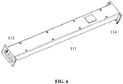
- the motor beams 11 as shown in the structure of FIG. 1 may include a first motor beam 111 and a second motor beam 112 arranged in parallel, and a specific structure of the first motor beam 111 may be referred to FIG. 4 .
- a length extension direction of the first motor beam 111 and a length extension direction of the second motor beam 112 coincide with an extension direction of a track 2, the first motor beam 111 and the second motor beam 112 are arranged opposite to each other, and the first motor beam 111 and the second motor beam 112 are arranged in a direction perpendicular to the extension direction of the track 2.
- each of both ends of each of the motor beams 11 is fixedly connected with one of the corbel 12.
- both ends of the first motor beam 111 are fixedly connected with a first corbel 121 and a second corbel 122 respectively
- both ends of the second motor beam 112 are fixedly connected with a third corbel 123 and a fourth corbel 124 respectively.
- Each of the corbels 12 is provided with an air spring mounting seat 125 at a top of each of the corbels, and the air spring mounting seat 125 is a cavity having an opening.
- the first corbel 121 is provided with a cavity having an opening at a top of the first corbel
- the second corbel 122 is provided with a cavity having an opening at a top of the second corbel
- the third corbel 123 is provided with a cavity having an opening at a top of the third corbel
- the fourth corbel 124 is provided with a cavity having an opening at a top of the fourth corbel.
- Each of the cavities accommodates one of the air springs 13.
- each of the cavities of the corbels 12 accommodates one of the air springs 13, and each of the air springs 13 is mounted with a sliding table 14 at a top of the each of the air springs.
- the maglev vehicle is carried and suspended by the air springs 13 and the sliding tables 14.
- Each of the corbels 12 of the above-mentioned suspension frame is provided with a cavity having an opening at the top of the each of the corbels, the cavity is used as the air spring mounting seat 125 so that the air spring 13 may be mounted inside the cavity of the corbel 12.
- the sliding table 14 is mounted on the air spring 13
- an airbag of the air spring 13 is completely located in the air spring mounting seat 125 in an non-working state, and most of the air spring 13 is located in the air spring mounting seat 125 in a working state, and the airbag can be attached to a cavity wall of the cavity to protect the airbag and ensure a transverse stability during an operation of the maglev vehicle.
- the airbag of the air spring 13 is located in the cavity, it is possible to eliminate the air spring dustproof cover sealing the air spring 13 in the related art, the transverse pull rod limiting the air spring 13 in the transverse direction and the air spring corbel beam.
- the air spring dustproof cover By eliminating the air spring dustproof cover, the transverse pull rod and the air spring corbel beam, the number and weight of parts of the suspension frame assembly can be reduced. Since the air spring 13 is mounted inside the corbel 12, the level of the air spring 13 can be lowered compared with the air spring 13 mounted at the top of the corbel 12 in the related art, thereby reducing the height of the center of gravity of the suspension frame assembly, and improving the operation stability of the maglev vehicle.
- the above-mentioned magnetic suspension assembly has the advantages of being small in weight, low in center of gravity, and unnecessary to provide an air spring dustproof cover, thereby solving the problems that the associated suspension frame 1 is large in weight, high in center of gravity, and needs to be provided with the dustproof cover.
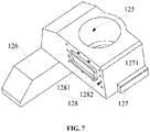
- each of the corbels 12 is provided with a motor beam mounting seat 128 for mounting the motor beam 11 on a side surface of the corbel facing toward the motor beam 11, the motor beam mounting seat 128 includes a positioning flange 1281 and a plurality of threaded holes 1282 provided around an outer peripheral of the positioning flange 1281.
- the positioning flange 1281 is a rectangular ring structure.
- the positioning flange 1281 may also be provided with rounded corners, as shown in the structures of FIG. 7 and FIG. 8 .
- the plurality of threaded holes 1282 may be uniformly distributed around the outer periphery of the positioning flange 1281, or the positions of the threaded holes 1282 may be arranged at random, or may be specifically arranged according to actual requirements.
- each of the both end surfaces of the motor beam 11 is provided with a positioning groove 113 corresponding to the positioning flange 1281 and inserted into and matched with the positioning flange, and motor beam through holes 114 corresponding to the threaded holes 1282 one to one.
- the positioning flange 1281 is inserted into and matched with the positioning groove 113, and fasteners 15 passing through the motor beam through holes 114 are screw-fitted with the corresponding threaded holes 1282.
- the corbel 12 can be positioned to be connected to the motor beam 11 by inserting the positioning flange 1281 into and matching the positioning flange with the positioning groove 113 between the corbel 12 and the motor beam 11. In this way, the speed of mounting the motor beam 11 with the corbel 12 can be increased, and the connection strength and stability between the corbel 12 and the motor beam 11 can also be improved.
- each suspension frame 1 may further include two anti-roll beam devices 16 mounted in parallel between the corbels 12, in which: one of the anti-roll beam devices 16 is mounted at an end of the motor beam 11 and the other one of the anti-roll beam devices 16 is mounted at an another end of the motor beam 11.
- the anti-roll beam devices 16 mounted between the corbels 12 can improve the anti-roll performance of the suspension frame assembly, thereby improving the stability and reliability of the suspension frame assembly, and further improving the operation stability and safety of the maglev vehicle.
- each of the anti-roll beam devices 16 may include a first anti-roll beam 161 and a second anti-roll beam 162 opposite to each other and hinged to each other.
- the first anti-roll beam 161 and the second anti-roll beam 162 are movably connected to each other by two suspenders 163, and an end of the first anti-roll beam 161 away from the second anti-roll beam 162 and an end of the second anti-roll beam 162 away from the first anti-roll beam 161 each are hinged with the corresponding corbel 12.
- the first anti-roll beam 161 and the second anti-roll beam 162 each include two fixedly connected anti-roll beam plates arranged in parallel, and the two anti-roll beam plates may be a first anti-roll beam plate 1611 and a second anti-roll beam plate 1612 arranged in parallel and riveted to each other.
- each of the suspension frames 1 further includes comprehensive brackets 17 corresponding to the corbels 12 one to one and fixedly connected to the corbels 12.
- Each of the comprehensive brackets 17 is provided with an anti-roll beam mounting seat 171, and the anti-roll beam mounting seat 171 is hinged to an end of the first anti-roll beam 161 or an end of the second anti-roll beam 162.
- the comprehensive bracket 17 is provided with an arc-shaped plate extending away from the corbel 12, and the arc-shaped plate forms the anti-roll beam mounting seat 171.
- the arc-shaped plate is provided with two hinge holes 1711 arranged at a top and a bottom of the arc-shaped plate respectively, and both the first anti-roll beam plate 1611 and the second anti-roll beam plate 1612 are provided with mounting holes corresponding to the hinge holes 1711, so that the hinge joint is realized by pin shafts passing through the corresponding mounting holes and the hinge holes 1711.
- At least two threaded holes 1282 which may be two, three, four, or more threaded holes 1282, of the plurality of threaded holes for mounting the motor beam 11 are positioned on a side close to the anti-roll beam device 16.
- the comprehensive bracket 17 is provided with fixing through holes 172 corresponding to the at least two threaded holes 1282 one to one. As shown in the structure of FIG.
- the comprehensive bracket 17 is provided with four fixing through holes 172, the four fasteners 15 sequentially pass through the fixing through holes 172 and the motor beam through holes 114 and then are screw-fitted with the corresponding threaded holes 1282, to fixedly connect the comprehensive bracket 17, the motor beam 11, and the corbel 12 together.
- the comprehensive bracket 17 and the motor beam 11 are fixed by means of the same threaded holes 1282 on the corbel 12, so that the comprehensive bracket 17 and the motor beam 11 can be mounted to the corbel 12 by the fasteners 15, which not only lessens the mounting process, saves the mounting time, but also reduces the number of the fasteners 15, thereby reducing the cost while reducing the weight of the suspension frame 1.
- the suspension frame 1 further includes hydraulic support wheels 18 supporting the suspension frame 1 and rolling on a track 2.
- the hydraulic support wheel 18 includes a hydraulic device 181 mounted on each of the comprehensive brackets 17, and a support wheel 182 corresponding to the hydraulic device 181 and mounted at a bottom of the hydraulic device 181.
- the comprehensive bracket 17 corresponding to each of the corbels 12 is mounted with two hydraulic support wheels 18, and therefore each of the suspension frame assemblies is provided with a total of eight hydraulic support wheels 18.
- each of the comprehensive brackets 17 is provided with two through holes 173 having axes extending in a vertical direction, and each of the through holes 173 is mounted with one hydraulic device 181, as shown in the structure of FIG. 8 .
- the motor beams 11 may be hollow beams having cavities, and bottom surfaces of the motor beams 11 are provided with linear motor mounting seats (not shown).
- the suspension frame 1 further includes linear motors 19 fixedly connected to the linear motor mounting seats, and the linear motors 19 are configured for providing traction for the maglev vehicle.
- the corbels 12 are, at bottoms of side surfaces of the corbels facing toward the motor beams 11, provided with suspension electromagnet mounting seats 126 extending toward the motor beams 11, and the suspension electromagnet mounting seats 126 are configured for mounting suspension electromagnets 21.
- the suspension frame 1 further includes suspension electromagnets 21 fixedly mounted on the suspension electromagnet mounting seats 126 and configured for providing suspension force. The suspension electromagnets 21 provide the suspension force for the suspension frame assembly, so that the suspension frame assembly is suspended on the track 2.
- the suspension frame 1 may further include a motor protection wheel 20 mounted at a bottom of each of the corbels 12, as shown in the structure of FIG. 8 .
- the motor protection wheel 20 is configured so that the maglev vehicle contacts the track 2 during the emergency landing to protect the linear motor 19.
- the suspension frame 1 further includes a brake device 22.
- the brake device 22 may include a brake clamp mounted on the suspension electromagnet 21, and may further include a hydraulic cylinder or a pneumatic cylinder for supplying a brake force to the brake clamp, and a pipeline for communicating the hydraulic cylinder or the pneumatic cylinder with the brake clamp.
- the suspension frame 1 may further include skid devices 23 for supporting the suspension frame 1 during a landing and/or for performing a brake operation during an emergency landing.
- the corbels 12 are provided with skid device mounting seats 127 at bottoms of surfaces of the corbels facing toward inside of the suspension frame 1.
- the skid devices 23 are fixedly mounted on the skid device mounting seats 127.
- the skid device mounting seats 127 are fixed blocks protruding from the bottoms and the side surfaces of the corbels 12.
- Limiting rims 1271 for limiting the skid devices 23 in a vertical direction are provided at tops of the skid device mounting seats 127.
- the suspension frame 1 further includes a sliding table 14 fixedly connected to a top of each of the air springs 13.
- a vehicle body of the maglev vehicle is supported by the sliding table 14, so that the suspension frame assembly is fixedly connected to the vehicle body, and the vehicle body moves along the track 2 under the drive of the suspension frame assembly.
- a second aspect of embodiments of the present application provides a maglev vehicle including the suspension frame assembly in any one of the above embodiments.
- the suspension frame assembly eliminates the air spring dustproof cover, the transverse pull rod, and the air spring corbel beam, the weight and the number of the parts of the maglev vehicle can be reduced, and thus the energy consumption and the cost of the maglev vehicle can further be reduced.
Abstract
Description
- The present application relates to the technical field of rail vehicles, and particularly to a maglev vehicle and a suspension frame assembly for the maglev vehicle.
- With the continuous rise of subway, subway lines are being built all over our country. However, conventional wheel-rail subways have a high requirement for foundation, and a route on a road surface has a problem of large noise. In addition, the construction of the ground routes in cities is limited by buildings and topography, and it is difficult to achieve a route with large climbing capacity and small curve radius. Therefore, a medium-low speed maglev train, as a new type of rail vehicle, is more and more popular in cities, and has the advantages of a low noise, strong acceleration and braking abilities, a strong climbing ability, a small turning radius, a small vibration, and a good comfort.
- As one of important components of a maglev vehicle, a suspension frame assembly affects an operation performance of the maglev vehicle. The associated suspension frame assembly includes a plurality of suspension frames sequentially connected to each other. Each of the suspension frames is fixedly provided with a corbel at each of both ends of a longitudinal beam body. The corbel is mounted with an air spring corbel beam for mounting an air spring, and an air spring mounting seat is provided on the air spring corbel beam. Since the air spring is mounted above the corbel, an airbag of the air spring is exposed to the air, an air spring dustproof cover needs to be provided to protect the air spring, which results in problems that the suspension frame is large in weight, high in center of gravity, and needs to be provided with the dustproof cover.
- Embodiments of the present application provide a maglev vehicle and a suspension frame assembly for the maglev vehicle. The suspension frame assembly uses a cavity provided on a corbel as an air spring mounting seat, so that an air spring is disposed inside the corbel. The suspension frame assembly not only eliminates an air spring dustproof cover, a transverse pull rod, and an air spring corbel beam, but also lowers a level of a top surface of the air spring, thereby solving problems that the associated suspension frame is large in weight, high in center of gravity, and needs to be provided with the air spring dust proof cover.
- A first aspect of embodiments of the present application provides a suspension frame assembly for a maglev vehicle, the suspension frame assembly includes a plurality of suspension frames sequentially connected to each other; each of the suspension frames includes two motor beams, four corbels, and four air springs.
- The two motor beams are arranged in parallel.
- Each of both ends of each of the motor beams is fixedly connected with one of the corbels.
- Each of the corbels is provided with an air spring mounting seat at a top of each of the corbels, the air spring mounting seat is a cavity having an opening.
- Each cavity accommodates one of the air springs.
- In some alternative embodiments, the corbel is provided with a motor beam mounting seat for mounting the motor beam on a side surface of the corbel facing toward the motor beam, the motor beam mounting seat includes a positioning flange and a plurality of threaded holes provided around an outer peripheral of the positioning flange.
- Each of the both end surfaces of the motor beam is provided with a positioning groove corresponding to the positioning flange and inserted into and matched with the positioning flange, and motor beam through holes corresponding to the threaded holes one to one.
- When the corbel is fixedly connected to the motor beam, the positioning flange is inserted into and matched with the positioning groove, and fasteners passing through the motor beam through holes are screw-fitted with the corresponding threaded holes.
- In some alternative embodiments, each of the suspension frames may further include two anti-roll beam devices mounted in parallel between the corbels.
- One of the anti-roll beam devices is mounted at an end of the motor beam, and the other one of the anti-roll beam devices is mounted at an another end of the motor beam.
- In some alternative embodiments, each of the anti-roll beam devices includes a first anti-roll beam and a second anti-roll beam opposite to each other and hinged to each other.
- The first anti-roll beam and the second anti-roll beam are movably connected to each other by two suspenders, and an end of the first anti-roll beam away from the second anti-roll beam and an end of the second anti-roll beam away from the first anti-roll beam each are hinged with the corresponding corbel.
- In some alternative embodiments, the first anti-roll beam and the second anti-roll beam each include two fixedly connected anti-roll beam plates arranged in parallel.
- In some alternative embodiments, each of the suspension frames may further include comprehensive brackets corresponding to the corbels one to one and fixedly connected to the corbels.
- Each of the comprehensive brackets is provided with an anti-rolling beam mounting seat, and the anti-roll beam mounting seat is hinged to an end of the first anti-roll beam or an end of the second anti-roll beam.
- In some alternative embodiments, at least two threaded holes of the plurality of threaded holes are positioned on a side close to the anti-roll beam device, the comprehensive bracket is provided with fixing through holes corresponding to the at least two threaded holes one to one, the fasteners sequentially pass through the fixing through holes and the motor beam through holes and then are screw-fitted with the corresponding threaded holes, to fixedly connect the comprehensive bracket, the motor beam, and the corbel together.
- In some alternative embodiments, the suspension frame may further include hydraulic support wheels for supporting the suspension frame and rolling on a track.
- Each of the hydraulic support wheels includes a hydraulic device mounted on each of the comprehensive brackets, and a support wheel corresponding to the hydraulic device and mounted at a bottom of the hydraulic device.
- In some alternative embodiments, each of the comprehensive brackets is provided with two through holes having axes extending in a vertical direction, and each of through holes is mounted with the hydraulic device.
- In some alternative embodiments, the motor beams are hollow beams having cavities, and bottom surfaces of the motor beams are provided with linear motor mounting seats.
- In some alternative embodiments, the suspension frame may further include linear motors fixedly connected to the linear motor mounting seats for providing traction.
- In some alternative embodiments, the suspension frame may further include a motor protection wheel mounted at a bottom of each of the corbels and the motor protection wheel is configured so that the maglev vehicle contacts the track during an emergency landing to protect the linear motor.
- In some alternative embodiments, the corbels are, at bottoms of side surfaces of the corbels facing toward the motor beams, provided with suspension electromagnet mounting seats extending toward the motor beams.
- The suspension frame may further include suspension electromagnets fixedly mounted on the suspension electromagnet mounting seats and configured for providing suspension force.
- In some alternative embodiments, the suspension frame may further include brake devices.
- The brake devices include brake clamps mounted on the suspension electromagnets.
- In some alternative embodiments, the suspension frame may further include skid devices for supporting the suspension frame during a landing and/or for performing a brake operation during an emergency landing.
- The corbels are provided with skid device mounting seats at bottoms of surfaces of the corbels facing toward inside of the suspension frame.
- The skid devices are fixedly mounted on the skid device mounting seats.
- In some alternative embodiments, the skid device mounting seats are fixed blocks protruding from bottoms and side surfaces of the corbels, and limiting rims for limiting the skid devices in a vertical direction are provided at tops of the skid device mounting seats.
- In some alternative embodiments, the suspension frame may further include a sliding table fixedly connected to a top of each of the air springs.
- A second aspect of embodiments of the present application provides a maglev vehicle including the suspension frame assembly in any one of the above-described technical solutions.
- According to the maglev vehicle and the suspension frame assembly for the maglev vehicle provided in the embodiments of the present application, the suspension frame assembly uses the cavity having the opening as the air spring mounting seat, the air spring is mounted in the cavity of the corbel, and the air spring is positioned in the cavity of the corbel by a cover of a sliding table. Meanwhile, a displacement of the air spring in a horizontal direction can be limited by a cooperation of the air spring and a cavity wall of the cavity. The suspension frame assembly can not only eliminate the air spring dustproof cover, the transverse pull rod, and the air spring corbel beam used in the related art, but also lower the level of the air spring, thereby reducing the center of gravity of the suspension frame assembly, and improving the operation stability of the maglev vehicle provided with the suspension frame assembly. Therefore, the above-mentioned magnetic suspension assembly has the advantages of being small in weight, low in center of gravity, and unnecessary to provide the air spring dustproof cover, thereby solving the problems that each of the associated suspension frame is large in weight, high in center of gravity, and needs to be provided with the dustproof cover.
- The accompanying drawings illustrated herein are used to provide a further understanding of the present application, which constitute a part of the present application, and the illustrative embodiments of the present application and the description thereof are used to explain the present application, but do not constitute an improper limitation of the present application. In the accompanying drawings:
-
FIG. 1 is a schematic structural view showing a suspension frame assembly provided by an embodiment of the present application; -
FIG. 2 is a schematic structural view showing the suspension frame assembly ofFIG. 1 , in which sliding tables and air springs are not mounted; -
FIG. 3 is a partially enlarged schematic view of a portion A of the suspension frame assembly ofFIG. 2 ; -
FIG. 4 is a schematic structural view showing a motor beam of the suspension frame assembly ofFIG. 1 ; -
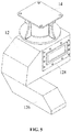
FIG. 5 is a schematic structural view showing the air spring, the sliding table and the corbel ofFIG. 1 assembled together; -
FIG. 6 is a schematic structural view showing the air spring, the sliding table and the corbel ofFIG. 5 disassembled from each other; -
FIG. 7 is a schematic structural view showing one side of the corbel ofFIG. 1 ; -
FIG. 8 is a schematic structural view showing an another side of the corbel ofFIG. 7 ; -
FIG. 9 is a schematic structural view showing a comprehensive bracket of the suspension frame assembly ofFIG. 1 . -
- 1: suspension frame; 2: track; 11: motor beam; 12: corbel; 13: air spring; 14: sliding table; 15: fastener; 16: anti-roll beam device; 17: comprehensive bracket; 18: hydraulic support wheel; 19: linear motor; 20: motor protection wheel; 21: suspension electromagnet; 22: brake device; 23: skid device;
- 111: first motor beam; 112: second motor beam; 113: positioning groove; 114: motor beam through hole; 121: first corbel; 122: second corbel; 123: third corbel; 124: fourth corbel; 125: air spring mounting seat; 126: suspension electromagnet mounting seat; 127: skid device mounting seat; 128: motor beam mounting seat; 161: first anti-roll beam; 162: second anti-roll beam; 163: suspender; 171: anti-roll beam mounting seat; 172: fixing through hole; 173: through hole; 181: hydraulic device; 182: support wheel;
- 1271: limiting rim; 1281: positioning flange; 1282: threaded hole; 1611: first anti-roll beam plate; 1612: second anti-roll beam plate; and 1711: hinge hole.
- In carrying out the present application, it has been found by the skilled person that air springs of a suspension frame are mounted above corbels, an airbag of each of the air springs is exposed to the air, and an air spring dustproof cover needs to be provided to protect each of the air springs, which results in problems that the suspension frame is large in weight, high in center of gravity, and needs to be provided with the dustproof cover.
- In view of the above problems, embodiments of the present application provide a maglev vehicle and a suspension frame assembly for a maglev vehicle, the suspension frame assembly allows an air spring to be mounted in a cavity at the top of a corbel so as to eliminate the air spring dustproof cover, the transverse pull rod, and the air spring corbel beam used in the related art. Therefore, the above-mentioned magnetic suspension assembly has the advantages of being small in weight, low in center of gravity, and unnecessary to provide an air spring dustproof cover.
- In order to make the technical solutions and advantages of the embodiments of the present application clearer, the exemplary embodiments of the present application will be further described in detail below with reference to the accompanying drawings. Apparently, the described embodiments are merely a part of the embodiments of the present application, rather than an exhaustive list of all the embodiments. It should be noted that the embodiments in the present application and the features in the embodiments can be combined with each other in the case of no conflict.
- A first aspect of embodiments of the present application provides a suspension frame assembly for a maglev vehicle. As shown in
FIG. 1 andFIG. 2 , the suspension frame assembly includes a plurality of suspension frames 1 sequentially connected to each other. Each of the suspension frames 1 includes twomotor beams 11, fourcorbels 12 and four air springs 13. - The two
motor beams 11 are arranged in parallel. The motor beams 11 as shown in the structure ofFIG. 1 may include afirst motor beam 111 and asecond motor beam 112 arranged in parallel, and a specific structure of thefirst motor beam 111 may be referred toFIG. 4 . A length extension direction of thefirst motor beam 111 and a length extension direction of thesecond motor beam 112 coincide with an extension direction of atrack 2, thefirst motor beam 111 and thesecond motor beam 112 are arranged opposite to each other, and thefirst motor beam 111 and thesecond motor beam 112 are arranged in a direction perpendicular to the extension direction of thetrack 2. - Each of both ends of each of the motor beams 11 is fixedly connected with one of the
corbel 12. As shown in the structure ofFIG. 2 , both ends of thefirst motor beam 111 are fixedly connected with afirst corbel 121 and asecond corbel 122 respectively, and both ends of thesecond motor beam 112 are fixedly connected with athird corbel 123 and afourth corbel 124 respectively. - Each of the
corbels 12 is provided with an airspring mounting seat 125 at a top of each of the corbels, and the airspring mounting seat 125 is a cavity having an opening. As shown in the structures ofFIG. 2 andFIG. 3 , thefirst corbel 121 is provided with a cavity having an opening at a top of the first corbel, thesecond corbel 122 is provided with a cavity having an opening at a top of the second corbel, thethird corbel 123 is provided with a cavity having an opening at a top of the third corbel, and thefourth corbel 124 is provided with a cavity having an opening at a top of the fourth corbel. - Each of the cavities accommodates one of the air springs 13. As shown in the structure of
FIG. 6 , each of the cavities of thecorbels 12 accommodates one of the air springs 13, and each of the air springs 13 is mounted with a sliding table 14 at a top of the each of the air springs. The maglev vehicle is carried and suspended by the air springs 13 and the sliding tables 14. - Each of the
corbels 12 of the above-mentioned suspension frame is provided with a cavity having an opening at the top of the each of the corbels, the cavity is used as the airspring mounting seat 125 so that theair spring 13 may be mounted inside the cavity of thecorbel 12. When the sliding table 14 is mounted on theair spring 13, an airbag of theair spring 13 is completely located in the airspring mounting seat 125 in an non-working state, and most of theair spring 13 is located in the airspring mounting seat 125 in a working state, and the airbag can be attached to a cavity wall of the cavity to protect the airbag and ensure a transverse stability during an operation of the maglev vehicle. Since the airbag of theair spring 13 is located in the cavity, it is possible to eliminate the air spring dustproof cover sealing theair spring 13 in the related art, the transverse pull rod limiting theair spring 13 in the transverse direction and the air spring corbel beam. By eliminating the air spring dustproof cover, the transverse pull rod and the air spring corbel beam, the number and weight of parts of the suspension frame assembly can be reduced. Since theair spring 13 is mounted inside thecorbel 12, the level of theair spring 13 can be lowered compared with theair spring 13 mounted at the top of thecorbel 12 in the related art, thereby reducing the height of the center of gravity of the suspension frame assembly, and improving the operation stability of the maglev vehicle. - Therefore, the above-mentioned magnetic suspension assembly has the advantages of being small in weight, low in center of gravity, and unnecessary to provide an air spring dustproof cover, thereby solving the problems that the associated suspension frame 1 is large in weight, high in center of gravity, and needs to be provided with the dustproof cover.
- In a specific embodiment, as shown in the structures of
FIG. 4 ,FIG. 5 andFIG. 8 , each of thecorbels 12 is provided with a motorbeam mounting seat 128 for mounting themotor beam 11 on a side surface of the corbel facing toward themotor beam 11, the motorbeam mounting seat 128 includes apositioning flange 1281 and a plurality of threadedholes 1282 provided around an outer peripheral of thepositioning flange 1281. As shown in the structures ofFIG. 5 andFIG. 6 , thepositioning flange 1281 is a rectangular ring structure. Thepositioning flange 1281 may also be provided with rounded corners, as shown in the structures ofFIG. 7 andFIG. 8 . The plurality of threadedholes 1282 may be uniformly distributed around the outer periphery of thepositioning flange 1281, or the positions of the threadedholes 1282 may be arranged at random, or may be specifically arranged according to actual requirements. - As shown in the structure of
FIG. 4 , each of the both end surfaces of themotor beam 11 is provided with apositioning groove 113 corresponding to thepositioning flange 1281 and inserted into and matched with the positioning flange, and motor beam throughholes 114 corresponding to the threadedholes 1282 one to one. - When the
corbel 12 is fixedly connected to themotor beam 11, thepositioning flange 1281 is inserted into and matched with thepositioning groove 113, andfasteners 15 passing through the motor beam throughholes 114 are screw-fitted with the corresponding threadedholes 1282. - The
corbel 12 can be positioned to be connected to themotor beam 11 by inserting thepositioning flange 1281 into and matching the positioning flange with thepositioning groove 113 between thecorbel 12 and themotor beam 11. In this way, the speed of mounting themotor beam 11 with thecorbel 12 can be increased, and the connection strength and stability between thecorbel 12 and themotor beam 11 can also be improved. - Specifically, as shown in the structures of
FIG. 1 ,FIG. 2 ,FIG. 3 andFIG. 8 , each suspension frame 1 may further include twoanti-roll beam devices 16 mounted in parallel between thecorbels 12, in which: one of theanti-roll beam devices 16 is mounted at an end of themotor beam 11 and the other one of theanti-roll beam devices 16 is mounted at an another end of themotor beam 11. - The
anti-roll beam devices 16 mounted between thecorbels 12 can improve the anti-roll performance of the suspension frame assembly, thereby improving the stability and reliability of the suspension frame assembly, and further improving the operation stability and safety of the maglev vehicle. - As shown in the structures of FIS. 2 and
FIG. 3 , each of theanti-roll beam devices 16 may include afirst anti-roll beam 161 and asecond anti-roll beam 162 opposite to each other and hinged to each other. - The
first anti-roll beam 161 and thesecond anti-roll beam 162 are movably connected to each other by twosuspenders 163, and an end of thefirst anti-roll beam 161 away from thesecond anti-roll beam 162 and an end of thesecond anti-roll beam 162 away from thefirst anti-roll beam 161 each are hinged with the correspondingcorbel 12. - As shown in the structures of
FIG. 2 andFIG. 3 , thefirst anti-roll beam 161 and thesecond anti-roll beam 162 each include two fixedly connected anti-roll beam plates arranged in parallel, and the two anti-roll beam plates may be a firstanti-roll beam plate 1611 and a secondanti-roll beam plate 1612 arranged in parallel and riveted to each other. - As shown in the structure of
FIG. 8 , each of the suspension frames 1 further includescomprehensive brackets 17 corresponding to thecorbels 12 one to one and fixedly connected to thecorbels 12. Each of thecomprehensive brackets 17 is provided with an anti-rollbeam mounting seat 171, and the anti-rollbeam mounting seat 171 is hinged to an end of thefirst anti-roll beam 161 or an end of thesecond anti-roll beam 162. As shown in the structure of theFIG. 8 , thecomprehensive bracket 17 is provided with an arc-shaped plate extending away from thecorbel 12, and the arc-shaped plate forms the anti-rollbeam mounting seat 171. The arc-shaped plate is provided with twohinge holes 1711 arranged at a top and a bottom of the arc-shaped plate respectively, and both the firstanti-roll beam plate 1611 and the secondanti-roll beam plate 1612 are provided with mounting holes corresponding to the hinge holes 1711, so that the hinge joint is realized by pin shafts passing through the corresponding mounting holes and the hinge holes 1711. - As shown in the structures of
FIG. 3 ,FIG. 5 , andFIG. 8 , at least two threadedholes 1282, which may be two, three, four, or more threadedholes 1282, of the plurality of threaded holes for mounting themotor beam 11 are positioned on a side close to theanti-roll beam device 16. Thecomprehensive bracket 17 is provided with fixing throughholes 172 corresponding to the at least two threadedholes 1282 one to one. As shown in the structure ofFIG. 8 , thecomprehensive bracket 17 is provided with four fixing throughholes 172, the fourfasteners 15 sequentially pass through the fixing throughholes 172 and the motor beam throughholes 114 and then are screw-fitted with the corresponding threadedholes 1282, to fixedly connect thecomprehensive bracket 17, themotor beam 11, and thecorbel 12 together. - The
comprehensive bracket 17 and themotor beam 11 are fixed by means of the same threadedholes 1282 on thecorbel 12, so that thecomprehensive bracket 17 and themotor beam 11 can be mounted to thecorbel 12 by thefasteners 15, which not only lessens the mounting process, saves the mounting time, but also reduces the number of thefasteners 15, thereby reducing the cost while reducing the weight of the suspension frame 1. - As shown in the structures of
FIG. 2 andFIG. 3 , the suspension frame 1 further includeshydraulic support wheels 18 supporting the suspension frame 1 and rolling on atrack 2. Thehydraulic support wheel 18 includes ahydraulic device 181 mounted on each of thecomprehensive brackets 17, and asupport wheel 182 corresponding to thehydraulic device 181 and mounted at a bottom of thehydraulic device 181. Thecomprehensive bracket 17 corresponding to each of thecorbels 12 is mounted with twohydraulic support wheels 18, and therefore each of the suspension frame assemblies is provided with a total of eighthydraulic support wheels 18. - In order to reduce the number of parts, each of the
comprehensive brackets 17 is provided with two throughholes 173 having axes extending in a vertical direction, and each of the throughholes 173 is mounted with onehydraulic device 181, as shown in the structure ofFIG. 8 . - In order to reduce the overall weight of the suspension frame 1, the motor beams 11 may be hollow beams having cavities, and bottom surfaces of the motor beams 11 are provided with linear motor mounting seats (not shown). The suspension frame 1 further includes
linear motors 19 fixedly connected to the linear motor mounting seats, and thelinear motors 19 are configured for providing traction for the maglev vehicle. - As shown in the structures of
FIG. 2 andFIG. 6 , thecorbels 12 are, at bottoms of side surfaces of the corbels facing toward the motor beams 11, provided with suspensionelectromagnet mounting seats 126 extending toward the motor beams 11, and the suspensionelectromagnet mounting seats 126 are configured for mountingsuspension electromagnets 21. The suspension frame 1 further includessuspension electromagnets 21 fixedly mounted on the suspensionelectromagnet mounting seats 126 and configured for providing suspension force. The suspension electromagnets 21 provide the suspension force for the suspension frame assembly, so that the suspension frame assembly is suspended on thetrack 2. - In order to prevent the maglev vehicle from damaging the
linear motor 19 during an emergency landing, the suspension frame 1 may further include amotor protection wheel 20 mounted at a bottom of each of thecorbels 12, as shown in the structure ofFIG. 8 . Themotor protection wheel 20 is configured so that the maglev vehicle contacts thetrack 2 during the emergency landing to protect thelinear motor 19. - As shown in the structures of
FIG. 1 andFIG. 2 , the suspension frame 1 further includes abrake device 22. Thebrake device 22 may include a brake clamp mounted on thesuspension electromagnet 21, and may further include a hydraulic cylinder or a pneumatic cylinder for supplying a brake force to the brake clamp, and a pipeline for communicating the hydraulic cylinder or the pneumatic cylinder with the brake clamp. - In order to improve the safety of the maglev vehicle, as shown in the structures of
FIG. 1 ,FIG. 2 andFIG. 3 , the suspension frame 1 may further includeskid devices 23 for supporting the suspension frame 1 during a landing and/or for performing a brake operation during an emergency landing. As shown in structure ofFIG. 7 , thecorbels 12 are provided with skiddevice mounting seats 127 at bottoms of surfaces of the corbels facing toward inside of the suspension frame 1. Theskid devices 23 are fixedly mounted on the skiddevice mounting seats 127. The skiddevice mounting seats 127 are fixed blocks protruding from the bottoms and the side surfaces of thecorbels 12. Limitingrims 1271 for limiting theskid devices 23 in a vertical direction are provided at tops of the skiddevice mounting seats 127. - As shown in the structure of
FIG. 1 , the suspension frame 1 further includes a sliding table 14 fixedly connected to a top of each of the air springs 13. A vehicle body of the maglev vehicle is supported by the sliding table 14, so that the suspension frame assembly is fixedly connected to the vehicle body, and the vehicle body moves along thetrack 2 under the drive of the suspension frame assembly. - A second aspect of embodiments of the present application provides a maglev vehicle including the suspension frame assembly in any one of the above embodiments.
- In the case that the maglev vehicle uses the above mentioned suspension frame assembly, since the suspension frame assembly eliminates the air spring dustproof cover, the transverse pull rod, and the air spring corbel beam, the weight and the number of the parts of the maglev vehicle can be reduced, and thus the energy consumption and the cost of the maglev vehicle can further be reduced.
- Although some alternative embodiments of the present application have been described, those skilled in the art can make additional changes and modifications to these embodiments once they learn the basic creative concept. Therefore, the claims are intended to be interpreted as including some alternative embodiments and all changes and modifications within the scope of the present application.
- Obviously, those skilled in the art can make various modifications and variations to this application without departing from the spirit and scope of the present application. In this way, if these modifications and variations of the present application fall into the scope of the claims of the present application and their equivalent technologies, the present application is also intended to include these modifications and variations.
Claims (18)
- A suspension frame assembly for a maglev vehicle, characterized in that the suspension frame assembly comprises a plurality of suspension frames sequentially connected to each other; each of the suspension frames comprising two motor beams, four corbels, and four air springs;
the two motor beams being arranged in parallel;
each of both ends of each of the motor beams being fixedly connected with one of the corbels;
each of the corbels being provided with an air spring mounting seat at a top of each of the corbels, the air spring mounting seat being a cavity having an opening; and
each cavity accommodating one of the air springs. - The suspension frame assembly according to claim 1, characterized in that the corbel is provided with a motor beam mounting seat for mounting the motor beam on a side surface of the corbel facing toward the motor beam, the motor beam mounting seat comprising a positioning flange and a plurality of threaded holes provided around an outer peripheral of the positioning flange;
each of both end surfaces of the motor beam being provided with a positioning groove corresponding to the positioning flange and inserted into and matched with the positioning flange, and motor beam through holes corresponding to the threaded holes one to one;
when the corbel is fixedly connected to the motor beam, the positioning flange is inserted into and matched with the positioning groove, and fasteners passing through the motor beam through holes are screw-fitted with the corresponding threaded holes. - The suspension frame assembly according to claim 2, characterized in that each of the suspension frames further comprises two anti-roll beam devices mounted in parallel between the corbels, and wherein,
one of the anti-roll beam devices is mounted at an end of the motor beam, and the other one of the anti-roll beam devices is mounted at an another end of the motor beam. - The suspension frame assembly according to claim 3, characterized in that each of the anti-roll beam devices comprises a first anti-roll beam and a second anti-roll beam opposite to each other and hinged to each other, and wherein:
the first anti-roll beam and the second anti-roll beam are movably connected to each other by two suspenders, and an end of the first anti-roll beam away from the second anti-roll beam and an end of the second anti-roll beam away from the first anti-roll beam each are hinged with the corresponding corbel. - The suspension frame assembly according to claim 4, characterized in that the first anti-roll beam and the second anti-roll beam each comprise two fixedly connected anti-roll beam plates arranged in parallel.
- The suspension frame assembly according to claim 4, characterized in that each of the suspension frames further comprises comprehensive brackets corresponding to the corbels one to one and fixedly connected to the corbels;
each of the comprehensive brackets being provided with an anti-roll beam mounting seat, and the anti-roll beam mounting seat being hinged to an end of the first anti-roll beam or an end of the second anti-roll beam. - The suspension frame assembly according to claim 6, characterized in that at least two threaded holes of the plurality of threaded holes are positioned on a side close to the anti-roll beam device, the comprehensive bracket being provided with fixing through holes corresponding to the at least two threaded holes one to one, the fasteners sequentially passing through the fixing through holes and the motor beam through holes and then being screw-fitted with the corresponding threaded holes, to fixedly connect the comprehensive bracket, the motor beam and the corbel together.
- The suspension frame assembly according to claim 6, characterized in that the suspension frame further comprises hydraulic support wheels for supporting the suspension frame and rolling on a track;
each of the hydraulic support wheels comprising a hydraulic device mounted on each of the comprehensive brackets, and a support wheel corresponding to the hydraulic device and mounted at a bottom of the hydraulic device. - The suspension frame assembly according to claim 8, characterized in that each of the comprehensive brackets is provided with two through holes having axes extending in a vertical direction, each of the through holes being mounted with the hydraulic device.
- The suspension frame assembly according to claim 1, characterized in that the motor beams are hollow beams having cavities, bottom surfaces of the motor beams being provided with linear motor mounting seats.
- The suspension frame assembly according to claim 10, characterized in that the suspension frame further comprises linear motors fixedly connected to the linear motor mounting seats for providing traction.
- The suspension frame assembly according to claim 10, characterized in that the suspension frame further comprises a motor protection wheel mounted at a bottom of each of the corbels, the motor protection wheel being configured so that the maglev vehicle contacts the track during an emergency landing to protect the linear motor.
- The suspension frame assembly according to claim 1, characterized in that the corbels are, at bottoms of side surfaces of the corbels facing towards the motor beams, provided with suspension electromagnet mounting seats extending toward the motor beams;
the suspension frame further comprising suspension electromagnets fixedly mounted on the suspension electromagnet mounting seats and configured for providing suspension force. - The suspension frame assembly according to claim 13, characterized in that the suspension frame further comprises brake devices;
the brake devices comprising brake clamps mounted on the suspension electromagnets. - The suspension frame assembly according to one of claims 1 to 14, characterized in that the suspension frame further comprises skid devices for supporting the suspension frame during a landing and/or for performing a brake operation during an emergency landing;
the corbels being provided with skid device mounting seats at bottoms of surfaces of the corbels facing toward inside of the suspension frame;
the skid devices being fixedly mounted on the skid device mounting seats. - The suspension frame assembly according to claim 15, characterized in that the skid device mounting seats are fixed blocks protruding from bottoms and side surfaces of the corbels, and limiting rims for limiting the skid devices in a vertical direction are provided at tops of the skid device mounting seats.
- The suspension frame assembly according to claim 15, characterized in that the suspension frame further comprises a sliding table fixedly connected to a top of each of the air springs.
- A maglev vehicle, characterized in that the maglev vehicle comprises the suspension frame assembly according to any one of claims 1 to 17.
Applications Claiming Priority (2)
| Application Number | Priority Date | Filing Date | Title |
|---|---|---|---|
| CN201811157992.3A CN110962621A (en) | 2018-09-30 | 2018-09-30 | Magnetic levitation vehicle and suspension frame assembly thereof |
| PCT/CN2018/113493 WO2020062429A1 (en) | 2018-09-30 | 2018-11-01 | Maglev vehicle and suspension frame assembly thereof |
Publications (2)
| Publication Number | Publication Date |
|---|---|
| EP3858655A1 true EP3858655A1 (en) | 2021-08-04 |
| EP3858655A4 EP3858655A4 (en) | 2021-12-01 |
Family
ID=69952806
Family Applications (1)
| Application Number | Title | Priority Date | Filing Date |
|---|---|---|---|
| EP18935863.3A Withdrawn EP3858655A4 (en) | 2018-09-30 | 2018-11-01 | Maglev vehicle and suspension frame assembly thereof |
Country Status (4)
| Country | Link |
|---|---|
| US (1) | US20210394801A1 (en) |
| EP (1) | EP3858655A4 (en) |
| CN (1) | CN110962621A (en) |
| WO (1) | WO2020062429A1 (en) |
Families Citing this family (3)
| Publication number | Priority date | Publication date | Assignee | Title |
|---|---|---|---|---|
| CN111762027B (en) * | 2020-06-12 | 2022-04-05 | 同济大学 | Suspension module structure of medium-low speed maglev train |
| CN112124085B (en) * | 2020-09-27 | 2022-03-18 | 中车唐山机车车辆有限公司 | Magnetic suspension carriage and magnetic suspension train |
| CN113933078A (en) * | 2021-09-22 | 2022-01-14 | 中车唐山机车车辆有限公司 | Test system of suspension frame |
Family Cites Families (17)
| Publication number | Priority date | Publication date | Assignee | Title |
|---|---|---|---|---|
| JP2007182110A (en) * | 2006-01-05 | 2007-07-19 | Jamco Corp | Normal-conducting attraction type magnetic levitated vehicle |
| CN100386228C (en) * | 2006-06-07 | 2008-05-07 | 西南交通大学 | Air spring for low speed magnetic suspension train |
| CN101101030A (en) * | 2007-06-01 | 2008-01-09 | 成都飞机工业(集团)有限责任公司 | Air spring with stop and limit device |
| CN101062662A (en) * | 2007-06-01 | 2007-10-31 | 成都飞机工业(集团)有限责任公司 | F rail vehicle running mechanism |
| CN201046707Y (en) * | 2007-06-01 | 2008-04-16 | 成都飞机工业(集团)有限责任公司 | Urban rail train anti-side-rolling device |
| CN201901013U (en) * | 2010-12-21 | 2011-07-20 | 西南交通大学 | Suspension unit structure of magnetic-levitation train |
| CN202170953U (en) * | 2011-07-16 | 2012-03-21 | 西南交通大学 | Free diaphragm type inclination prevention air spring |
| CN102352906A (en) * | 2011-07-16 | 2012-02-15 | 西南交通大学 | Free-film type anti-inclination air spring |
| CN102991519B (en) * | 2012-11-30 | 2016-09-07 | 常州西南交通大学轨道交通研究院 | The running mechanism of middle low speed magnetic suspension vehicle |
| CN102963266B (en) * | 2012-12-03 | 2015-02-11 | 中国人民解放军国防科学技术大学 | Magnetic suspension vehicle travelling unit in traction linear motor |
| CN203766544U (en) * | 2014-01-24 | 2014-08-13 | 同济大学 | Air spring and suspension device for medium-low speed maglev vehicle |
| CN105904995B (en) * | 2016-06-03 | 2018-03-02 | 中国人民解放军国防科学技术大学 | The suspension rack and magnetic suspension train put in a kind of frameless formula traction linear electric motors |
| CN206416877U (en) * | 2016-10-27 | 2017-08-18 | 天津信云风科技有限公司 | A kind of novel magnetically levitated rail system |
| CN106740252B (en) * | 2016-12-19 | 2023-04-07 | 西南交通大学 | Medium-low speed maglev vehicle suspension frame trailing arm structure |
| CN206856720U (en) * | 2017-06-13 | 2018-01-09 | 中车株洲电力机车有限公司 | A kind of continuous fiber reinforced composite materials suspension rack and low speed magnetic suspension train |
| CN107599888B (en) * | 2017-08-03 | 2019-08-27 | 中车青岛四方机车车辆股份有限公司 | The suspension rack component of maglev vehicle |
| CN110304092B (en) * | 2018-03-27 | 2020-08-04 | 中车唐山机车车辆有限公司 | Magnetic suspension bogie and train |
-
2018
- 2018-09-30 CN CN201811157992.3A patent/CN110962621A/en active Pending
- 2018-11-01 US US17/281,225 patent/US20210394801A1/en active Pending
- 2018-11-01 EP EP18935863.3A patent/EP3858655A4/en not_active Withdrawn
- 2018-11-01 WO PCT/CN2018/113493 patent/WO2020062429A1/en unknown
Also Published As
| Publication number | Publication date |
|---|---|
| EP3858655A4 (en) | 2021-12-01 |
| WO2020062429A1 (en) | 2020-04-02 |
| US20210394801A1 (en) | 2021-12-23 |
| CN110962621A (en) | 2020-04-07 |
Similar Documents
| Publication | Publication Date | Title |
|---|---|---|
| EP3858655A1 (en) | Maglev vehicle and suspension frame assembly thereof | |
| CN106004913B (en) | Bogie | |
| WO2019184055A1 (en) | Magnetic suspension bogie and train | |
| CN103523037A (en) | Track vehicle steering frame | |
| CN103879425A (en) | Non-power bogie for 100% low-floor vehicle | |
| EP2797800B1 (en) | Two-piece bogie with a novel suspension system | |
| WO2023093793A1 (en) | Bogie and rail vehicle | |
| WO2023093797A1 (en) | Double-layer side beam bogie and rail vehicle | |
| WO2023093801A1 (en) | Bogie with side beam fixing seat, and rail vehicle | |
| CN103863349A (en) | Power truck for 100% low-floor vehicle | |
| CN111348067A (en) | Bogie and rail vehicle | |
| CN110667635A (en) | Built-in bogie frame of axle box | |
| CN205930746U (en) | Steering frame | |
| CN112644542B (en) | Steering frame | |
| CN108327729B (en) | Empty indisputable system | |
| CN112298244A (en) | Rail vehicle and bogie thereof | |
| CN114084185B (en) | Bogie with safety stop and railway vehicle | |
| CN112758122B (en) | Bogie frame and have its bogie assembly and straddle type monorail vehicle | |
| US20150000551A1 (en) | Fabricated frame for railway truck | |
| CN211642185U (en) | Bogie end composite support | |
| CN217655623U (en) | Bogie for magnetic levitation trolley experiment system | |
| CN114084190B (en) | Single-layer side beam bogie and railway vehicle | |
| CN217623574U (en) | Electrically-driven bogie and railway engineering vehicle | |
| CN215204887U (en) | Suspension type maglev train | |
| CN214356041U (en) | Low-floor tramcar bogie capable of meeting wheelchair passing requirements |
Legal Events
| Date | Code | Title | Description |
|---|---|---|---|
| STAA | Information on the status of an ep patent application or granted ep patent |
Free format text: STATUS: THE INTERNATIONAL PUBLICATION HAS BEEN MADE |
|
| PUAI | Public reference made under article 153(3) epc to a published international application that has entered the european phase |
Free format text: ORIGINAL CODE: 0009012 |
|
| STAA | Information on the status of an ep patent application or granted ep patent |
Free format text: STATUS: REQUEST FOR EXAMINATION WAS MADE |
|
| 17P | Request for examination filed |
Effective date: 20210429 |
|
| AK | Designated contracting states |
Kind code of ref document: A1 Designated state(s): AL AT BE BG CH CY CZ DE DK EE ES FI FR GB GR HR HU IE IS IT LI LT LU LV MC MK MT NL NO PL PT RO RS SE SI SK SM TR |
|
| A4 | Supplementary search report drawn up and despatched |
Effective date: 20211104 |
|
| RIC1 | Information provided on ipc code assigned before grant |
Ipc: B61B 13/08 20060101ALI20211028BHEP Ipc: B61F 5/10 20060101ALI20211028BHEP Ipc: B61F 5/00 20060101ALI20211028BHEP Ipc: B60L 13/04 20060101AFI20211028BHEP |
|
| DAV | Request for validation of the european patent (deleted) | ||
| DAX | Request for extension of the european patent (deleted) | ||
| STAA | Information on the status of an ep patent application or granted ep patent |
Free format text: STATUS: THE APPLICATION IS DEEMED TO BE WITHDRAWN |
|
| 18D | Application deemed to be withdrawn |
Effective date: 20220604 |