EP3857767B1 - Kommunikation auf basis von funksignalmessungen - Google Patents
Kommunikation auf basis von funksignalmessungen Download PDFInfo
- Publication number
- EP3857767B1 EP3857767B1 EP19783882.4A EP19783882A EP3857767B1 EP 3857767 B1 EP3857767 B1 EP 3857767B1 EP 19783882 A EP19783882 A EP 19783882A EP 3857767 B1 EP3857767 B1 EP 3857767B1
- Authority
- EP
- European Patent Office
- Prior art keywords
- message
- signal strength
- feedback
- receiving
- transmitting device
- Prior art date
- Legal status (The legal status is an assumption and is not a legal conclusion. Google has not performed a legal analysis and makes no representation as to the accuracy of the status listed.)
- Active
Links
Images


Classifications
-
- H—ELECTRICITY
- H04—ELECTRIC COMMUNICATION TECHNIQUE
- H04L—TRANSMISSION OF DIGITAL INFORMATION, e.g. TELEGRAPHIC COMMUNICATION
- H04L1/00—Arrangements for detecting or preventing errors in the information received
- H04L1/12—Arrangements for detecting or preventing errors in the information received by using return channel
- H04L1/16—Arrangements for detecting or preventing errors in the information received by using return channel in which the return channel carries supervisory signals, e.g. repetition request signals
- H04L1/1607—Details of the supervisory signal
- H04L1/1692—Physical properties of the supervisory signal, e.g. acknowledgement by energy bursts
-
- H—ELECTRICITY
- H04—ELECTRIC COMMUNICATION TECHNIQUE
- H04W—WIRELESS COMMUNICATION NETWORKS
- H04W72/00—Local resource management
- H04W72/50—Allocation or scheduling criteria for wireless resources
- H04W72/54—Allocation or scheduling criteria for wireless resources based on quality criteria
- H04W72/542—Allocation or scheduling criteria for wireless resources based on quality criteria using measured or perceived quality
-
- H—ELECTRICITY
- H04—ELECTRIC COMMUNICATION TECHNIQUE
- H04B—TRANSMISSION
- H04B17/00—Monitoring; Testing
- H04B17/30—Monitoring; Testing of propagation channels
- H04B17/309—Measuring or estimating channel quality parameters
- H04B17/318—Received signal strength
-
- H—ELECTRICITY
- H04—ELECTRIC COMMUNICATION TECHNIQUE
- H04L—TRANSMISSION OF DIGITAL INFORMATION, e.g. TELEGRAPHIC COMMUNICATION
- H04L1/00—Arrangements for detecting or preventing errors in the information received
- H04L1/12—Arrangements for detecting or preventing errors in the information received by using return channel
- H04L1/16—Arrangements for detecting or preventing errors in the information received by using return channel in which the return channel carries supervisory signals, e.g. repetition request signals
- H04L1/18—Automatic repetition systems, e.g. Van Duuren systems
- H04L1/1812—Hybrid protocols; Hybrid automatic repeat request [HARQ]
-
- H—ELECTRICITY
- H04—ELECTRIC COMMUNICATION TECHNIQUE
- H04L—TRANSMISSION OF DIGITAL INFORMATION, e.g. TELEGRAPHIC COMMUNICATION
- H04L1/00—Arrangements for detecting or preventing errors in the information received
- H04L1/12—Arrangements for detecting or preventing errors in the information received by using return channel
- H04L1/16—Arrangements for detecting or preventing errors in the information received by using return channel in which the return channel carries supervisory signals, e.g. repetition request signals
- H04L1/18—Automatic repetition systems, e.g. Van Duuren systems
- H04L1/1867—Arrangements specially adapted for the transmitter end
- H04L1/1893—Physical mapping arrangements
-
- H—ELECTRICITY
- H04—ELECTRIC COMMUNICATION TECHNIQUE
- H04W—WIRELESS COMMUNICATION NETWORKS
- H04W4/00—Services specially adapted for wireless communication networks; Facilities therefor
- H04W4/02—Services making use of location information
- H04W4/023—Services making use of location information using mutual or relative location information between multiple location based services [LBS] targets or of distance thresholds
-
- H—ELECTRICITY
- H04—ELECTRIC COMMUNICATION TECHNIQUE
- H04W—WIRELESS COMMUNICATION NETWORKS
- H04W76/00—Connection management
- H04W76/10—Connection setup
- H04W76/14—Direct-mode setup
-
- H—ELECTRICITY
- H04—ELECTRIC COMMUNICATION TECHNIQUE
- H04W—WIRELESS COMMUNICATION NETWORKS
- H04W88/00—Devices specially adapted for wireless communication networks, e.g. terminals, base stations or access point devices
- H04W88/02—Terminal devices
- H04W88/04—Terminal devices adapted for relaying to or from another terminal or user
Definitions
- the present disclosure relates generally to communication systems, and more particularly, to vehicle-to-everything (V2X) communication, vehicle-to-vehicle (V2V), or other device-to-device (D2D) communication.
- V2X vehicle-to-everything
- V2V vehicle-to-vehicle
- D2D device-to-device
- Wireless communication systems are widely deployed to provide various telecommunication services such as telephony, video, data, messaging, and broadcasts.
- Typical wireless communication systems may employ multiple-access technologies capable of supporting communication with multiple users by sharing available system resources. Examples of such multiple-access technologies include code division multiple access (CDMA) systems, time division multiple access (TDMA) systems, frequency division multiple access (FDMA) systems, orthogonal frequency division multiple access (OFDMA) systems, single-carrier frequency division multiple access (SC-FDMA) systems, and time division synchronous code division multiple access (TD-SCDMA) systems.
- CDMA code division multiple access
- TDMA time division multiple access
- FDMA frequency division multiple access
- OFDMA orthogonal frequency division multiple access
- SC-FDMA single-carrier frequency division multiple access
- TD-SCDMA time division synchronous code division multiple access
- 5G New Radio is part of a continuous mobile broadband evolution promulgated by Third Generation Partnership Project (3GPP) to meet new requirements associated with latency, reliability, security, scalability (e.g., with Internet of Things (IoT)), and other requirements.
- 3GPP Third Generation Partnership Project
- 5G NR includes services associated with enhanced mobile broadband (eMBB), massive machine type communications (mMTC), and ultra reliable low latency communications (URLLC).
- eMBB enhanced mobile broadband
- mMTC massive machine type communications
- URLLC ultra reliable low latency communications
- Some aspects of 5G NR may be based on the 4G Long Term Evolution (LTE) standard. Some communication may be performed directly between User Equipment (UEs).
- UEs User Equipment
- Patent application WO 2017/103662 relates to a method for receiving a data packet from a first communication device by a second communication device in a wireless network comprising the following steps: - awaiting the data packet at the second communication device; determining a context information related to the data packet by the second communication device; if the data packet is not received successfully, controlling transmission of a negative acknowledgement indicator, NACK, and/or transmission of a channel quality indicator, CQI, by the second communication device to the first communication device based on the context information.
- NACK negative acknowledgement indicator
- CQI channel quality indicator
- a method for wireless communication at a receiving device.
- the method includes receiving, from a transmitting device, at least a portion of a message for a service group, wherein the message comprises a D2D message and measuring a signal strength for the message received from the transmitting device.
- the method includes determining whether the receiving device is within a range of the transmitting device based on the measured signal strength for the message and determining to send Hybrid Automatic Repeat Request (HARQ) feedback to the transmitting device when the receiving device is within the range of the transmitting device.
- HARQ Hybrid Automatic Repeat Request
- an apparatus for wireless communication at a receiving device.
- the apparatus includes means for receiving, from a transmitting device, at least a portion of a message for a service group, wherein the message comprises a D2D message and means for measuring a signal strength for the received message received from the transmitting device.
- the apparatus includes means for determining whether the receiving device is within a range of the transmitting device based on the measured signal strength for the received message and means for determining to send Hybrid Automatic Repeat Request (HARQ) feedback to the transmitting device when the receiving device is within the range of the transmitting device.
- HARQ Hybrid Automatic Repeat Request
- a computer-readable medium for wireless communication at a receiving device.
- the computer-readable medium stores computer executable code for wireless communication at a receiving device, the code when executed by a processor cause the processor to receive, from a transmitting device, at least a portion of a message for a service group, wherein the message comprises a D2D message, measure a signal strength for the received message received from the transmitting device, determine whether the receiving device is within a range of the transmitting device based on the measured signal strength for the received message, and determine to Hybrid Automatic Repeat Request (HARQ) feedback to the transmitting device when the receiving device is within the range of the transmitting device.
- HARQ Hybrid Automatic Repeat Request
- a method for wireless communication at a transmitting device.
- the method includes transmitting a message to a service group for an intended range, wherein the message comprises a D2D message and receiving Hybrid Automatic Repeat Request (HARQ) feedback from at least one receiving device.
- the method includes measuring a signal strength for the HARQ feedback and determining whether the HARQ feedback is from a receiving device within the intended range based on the signal strength measured for the HARQ feedback.
- the method includes determining to resend the message when the HARQ feedback is from the receiving device within the intended range.
- HARQ Hybrid Automatic Repeat Request
- an apparatus for wireless communication at a transmitting device.
- the apparatus includes means for transmitting a message to a service group for an intended range, wherein the message comprises a D2D message.
- the apparatus includes means for receiving HARQ feedback from at least one receiving device and means for measuring a signal strength for the HARQ feedback.
- the apparatus includes means for determining whether the HARQ feedback is from a receiving device within the intended range based on the signal strength measured for the HARQ feedback and means for determining to resend the message when the HARQ feedback is from the receiving device within the intended range.
- a computer-readable medium for wireless communication at a transmitting device.
- the computer-readable medium stores computer executable code that, when executed by a processor, cause the processor to transmit a message to a service group for an intended range, wherein the message comprises a D2D message, receive HARQ feedback from at least one receiving device, measure a signal strength for the HARQ feedback, determine whether the HARQ feedback is from a receiving device within the intended range based on the signal strength measured for the HARQ feedback, and determine to resend the message when the HARQ feedback is from the receiving device within the intended range.
- the one or more aspects comprise the features hereinafter fully described and particularly pointed out in the claims.
- the following description and the annexed drawings set forth in detail certain illustrative features of the one or more aspects.
- Wireless communication may involve transmissions from a transmitting device for receipt by at least one receiving device.
- a transmitting device may transmit a message via V2V/V2X/D2D to a receiving vehicle.
- the message may be multicast from the transmitting device and may be intended to be reliably delivered to certain receiving devices, e.g., devices for a corresponding service group, within a certain area including the transmitting device.
- the transmitting device may listen for feedback from receiving devices(s) to determine whether the message was received correctly.
- Receiving device(s) that do not successfully receive the message may respond to the transmitting device with a Negative Acknowledgement (NACK).
- NACK Negative Acknowledgement
- the NACK may prompt the transmitting device to retransmit the message.
- a receiving device that is too distant from the transmitting device to correctly receive the message may respond with a NACK causing the transmitting device to retransmit the message in vain.
- Such feedback and wasted retransmissions for receiving devices that may be distant from the transmitting device degrade system performance. This problem may be especially challenging in a V2X/V2V/D2D environment due to the highly mobile nature of transmitters and/or receivers.
- the functions described may be implemented in hardware, software, or any combination thereof. If implemented in software, the functions may be stored on or encoded as one or more instructions or code on a computer-readable medium.
- Computer-readable media includes computer storage media. Storage media may be any available media that can be accessed by a computer.
- such computer-readable media can comprise a random-access memory (RAM), a read-only memory (ROM), an electrically erasable programmable ROM (EEPROM), optical disk storage, magnetic disk storage, other magnetic storage devices, combinations of the aforementioned types of computer-readable media, or any other medium that can be used to store computer executable code in the form of instructions or data structures that can be accessed by a computer.
- the base stations 102 may wirelessly communicate with the UEs 104. Each of the base stations 102 may provide communication coverage for a respective geographic coverage area 110. There may be overlapping geographic coverage areas 110. For example, the small cell 102' may have a coverage area 110' that overlaps the coverage area 110 of one or more base stations 102, e.g., macro base stations.
- a network that includes both small cell and macro cells may be known as a heterogeneous network.
- a heterogeneous network may also include Home Evolved Node Bs (eNBs) (HeNBs), which may provide service to a restricted group known as a closed subscriber group (CSG).
- eNBs Home Evolved Node Bs
- CSG closed subscriber group
- D2D communication link 158 may use the DL/UL WWAN spectrum.
- the D2D communication link 158 may use one or more sidelink channels, such as a physical sidelink broadcast channel (PSBCH), a physical sidelink discovery channel (PSDCH), a physical sidelink shared channel (PSSCH), and a physical sidelink control channel (PSCCH).
- sidelink channels such as a physical sidelink broadcast channel (PSBCH), a physical sidelink discovery channel (PSDCH), a physical sidelink shared channel (PSSCH), and a physical sidelink control channel (PSCCH).
- sidelink channels such as a physical sidelink broadcast channel (PSBCH), a physical sidelink discovery channel (PSDCH), a physical sidelink shared channel (PSSCH), and a physical sidelink control channel (PSCCH).
- sidelink channels such as a physical sidelink broadcast channel (PSBCH), a physical sidelink discovery channel (PSDCH), a physical sidelink shared channel (PSSCH), and a physical sidelink control channel (PSCCH).
- the EPC 160 may include a Mobility Management Entity (MME) 162, other MMEs 164, a Serving Gateway 166, a Multimedia Broadcast Multicast Service (MBMS) Gateway 168, a Broadcast Multicast Service Center (BM-SC) 170, and a Packet Data Network (PDN) Gateway 172.
- MME Mobility Management Entity
- MBMS Multimedia Broadcast Multicast Service
- BM-SC Broadcast Multicast Service Center
- PDN Packet Data Network
- the MME 162 may be in communication with a Home Subscriber Server (HSS) 174.
- HSS Home Subscriber Server
- the MME 162 is the control node that processes the signaling between the UEs 104 and the EPC 160.
- the MME 162 provides bearer and connection management. All user Internet protocol (IP) packets are transferred through the Serving Gateway 166, which itself is connected to the PDN Gateway 172.
- IP Internet protocol
- Examples of UEs 104 include a cellular phone, a smart phone, a session initiation protocol (SIP) phone, a laptop, a personal digital assistant (PDA), a satellite radio, a global positioning system, a multimedia device, a video device, a digital audio player (e.g., MP3 player), a camera, a game console, a tablet, a smart device, a wearable device, a vehicle, an electric meter, a gas pump, a large or small kitchen appliance, a healthcare device, an implant, a sensor/actuator, a display, or any other similar functioning device.
- SIP session initiation protocol
- PDA personal digital assistant
- the UEs 104 may be referred to as IoT devices (e.g., parking meter, gas pump, toaster, vehicles, heart monitor, etc.).
- the UE 104 may also be referred to as a station, a mobile station, a subscriber station, a mobile unit, a subscriber unit, a wireless unit, a remote unit, a mobile device, a wireless device, a wireless communications device, a remote device, a mobile subscriber station, an access terminal, a mobile terminal, a wireless terminal, a remote terminal, a handset, a user agent, a mobile client, a client, or some other suitable terminology.
- the message component 198 of UE 104 may be configured to receive HARQ feedback from at least the UE 104', measure a signal strength for the HARQ feedback, and determine whether to resend the message based on the signal strength measured for the HARQ feedback.
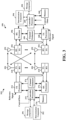
- FIG. 2 illustrates example diagrams 200 and 210 illustrating examples slot structures that may be used for wireless communication between UE 104 and UE 104, e.g., for sidelink communication.
- the slot structure may be within a 5G/NR frame structure.
- 5G NR 5G NR
- the concepts described herein may be applicable to other similar areas, such as LTE, LTE-A, CDMA, GSM, and other wireless technologies. This is merely one example, and other wireless communication technologies may have a different frame structure and/or different channels.
- a frame (10 ms) may be divided into 10 equally sized subframes (1 ms). Each subframe may include one or more time slots. Subframes may also include mini-slots, which may include 7, 4, or 2 symbols.
- Each slot may include 7 or 14 symbols, depending on the slot configuration. For slot configuration 0, each slot may include 14 symbols, and for slot configuration 1, each slot may include 7 symbols.
- Diagram 200 illustrates a single slot transmission, e.g., which may correspond to a 0.5 ms transmission time interval (TTI).
- Diagram 210 illustrates an example two-slot aggregation, e.g., an aggregation of two 0.5 ms TTIs.
- Diagram 200 illustrates a single RB, whereas diagram 210 illustrates N RBs. In diagram 210, 10 RBs being used for control is merely one example. The number of RBs may differ.
- a resource grid may be used to represent the frame structure.
- Each time slot may include a resource block (RB) (also referred to as physical RBs (PRBs)) that extends 12 consecutive subcarriers.
- RB resource block
- PRBs physical RBs
- the resource grid is divided into multiple resource elements (REs). The number of bits carried by each RE depends on the modulation scheme.
- some of the REs may comprise control information, e.g., along with demodulation RS (DMRS).
- DMRS demodulation RS
- the control information may indicate an intended range for corresponding data. The intended range may help devices receiving the data to determine whether to provide feedback to the device that transmitted the data.
- FIG. 2 also illustrates that symbol(s) may comprise CSI-RS. The symbols in FIG.
- CSI-RS indicates that the symbol comprises DMRS or CSI-RS REs.
- Such symbols may also comprise REs that include data. For example, if a number of ports for DMRS or CSI-RS is 1 and a comb-2 pattern is used for DMRS/CSI-RS, then half of the REs may comprise the RS and the other half of the REs may comprise data.
- a CSI-RS resource may start at any symbol of a slot, and may occupy 1, 2, or 4 symbols depending on a configured number of ports.
- CSI-RS can be periodic, semi-persistent, or aperiodic (e.g., based on DCI triggering). For time/frequency tracking, CSI-RS may be either periodic or aperiodic.
- CSI-RS may be transmitted in bursts of two or four symbols that are spread across one or two slots.
- the control information may comprise Sidelink Control Information (SCI).
- SCI Sidelink Control Information
- At least one symbol may be used for feedback, as described herein.
- a symbol prior to and/or after the feedback may be used for turnaround between reception of data and transmission of the feedback.
- symbol 12 is illustrated for data, it may instead be a gap symbol to enable turnaround for feedback in symbol 13.
- Another symbol, e.g., at the end of the slot may be used as a gap.
- the gap enables a device to switch from operating as a transmitting device to prepare to operate as a receiving device, e.g., in the following slot.
- Data may be transmitted in the remaining REs, as illustrated.
- the data may comprise the data message described herein.
- the position of any of the SCI, feedback, and LBT symbols may be different than the example illustrated in FIG. 2 .
- Multiple slots may be aggregated together.
- FIG. 2 also illustrates an example aggregation of two slots.
- the aggregated number of slots may also be larger than two.
- the symbols used for feedback and/or a gap symbol may be different that for a single slot. While feedback is not illustrated for the aggregated example, symbol(s) in a multiple slot aggregation may also be allocated for feedback, as illustrated in the one slot example.
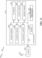
- FIG. 3 is a block diagram 300 of a first wireless communication device 310 in communication with a second wireless communication device 350, e.g., via V2V/V2X/D2D communication.
- the device 310 may comprise a transmitting device communicating with a receiving device, e.g., device 350, via V2V/V2X/D2D communication.
- the communication may be based, e.g., on sidelink.
- the first wireless communication device 310 may comprise a UE, an RSU, etc.
- the receiving device may comprise a UE, an RSU, etc.
- the wireless communication devices 310, 350 may each comprise a message component 391, 393 and/or a determination component 392, 394.
- the message component 391, 393 may be configured to generate and transmit a message for the service group based, at least in part, on the intended range.
- the message component 391, 393 may also be configured to determine whether to retransmit a message based on a signal strength of feedback received from receiving device(s).
- the determination component 392, 394 may be configured to determine whether to send a feedback for the message based on a signal strength of at least a portion of the message.
- least one of the TX processor 368, the RX processor 356, or the controller/processor 359 of device 350 or the TX processor 316, the RX processor 370, or the controller/processor 375 may be configured to perform aspects described in connection with 198 and/or 199 of FIG. 1 .
- Packets may be provided to a controller/processor 375 that implements layer 3 and layer 2 functionality.
- Layer 3 includes a radio resource control (RRC) layer
- layer 2 includes a packet data convergence protocol (PDCP) layer, a radio link control (RLC) layer, and a medium access control (MAC) layer.
- RRC radio resource control
- PDCP packet data convergence protocol
- RLC radio link control
- MAC medium access control
- the transmit (TX) processor 316 and the receive (RX) processor 370 implement layer 1 functionality associated with various signal processing functions.
- Layer 1 which includes a physical (PHY) layer, may include error detection on the transport channels, forward error correction (FEC) coding/decoding of the transport channels, interleaving, rate matching, mapping onto physical channels, modulation/demodulation of physical channels, and MIMO antenna processing.
- the TX processor 316 handles mapping to signal constellations based on various modulation schemes (e.g., binary phase-shift keying (BPSK), quadrature phase-shift keying (QPSK), M-phase-shift keying (M-PSK), M-quadrature amplitude modulation (M-QAM)).
- BPSK binary phase-shift keying
- QPSK quadrature phase-shift keying
- M-PSK M-phase-shift keying
- M-QAM M-quadrature amplitude modulation
- each receiver 354RX receives a signal through its respective antenna 352.
- Each receiver 354RX recovers information modulated onto an RF carrier and provides the information to the receive (RX) processor 356.
- the TX processor 368 and the RX processor 356 implement layer 1 functionality associated with various signal processing functions.
- the RX processor 356 may perform spatial processing on the information to recover any spatial streams destined for the device 350. If multiple spatial streams are destined for the device 350, they may be combined by the RX processor 356 into a single OFDM symbol stream.
- the RX processor 356 then converts the OFDM symbol stream from the time-domain to the frequency domain using a Fast Fourier Transform (FFT).
- FFT Fast Fourier Transform
- the symbols on each subcarrier, and the reference signal, are recovered and demodulated by determining the most likely signal constellation points transmitted by device 310. These soft decisions may be based on channel estimates computed by the channel estimator 358. The soft decisions are then decoded and deinterleaved to recover the data and control signals that were originally transmitted by device 310 on the physical channel. The data and control signals are then provided to the controller/processor 359, which implements layer 3 and layer 2 functionality.
- the controller/processor 359 may provide RRC layer functionality associated with system information (e.g., MIB, SIBs) acquisition, RRC connections, and measurement reporting; PDCP layer functionality associated with header compression / decompression, and security (ciphering, deciphering, integrity protection, integrity verification); RLC layer functionality associated with the transfer of upper layer PDUs, error correction through ARQ, concatenation, segmentation, and reassembly of RLC SDUs, re-segmentation of RLC data PDUs, and reordering of RLC data PDUs; and MAC layer functionality associated with mapping between logical channels and transport channels, multiplexing of MAC SDUs onto TBs, demultiplexing of MAC SDUs from TBs, scheduling information reporting, error correction through HARQ, priority handling, and logical channel prioritization.
- RRC layer functionality associated with system information (e.g., MIB, SIBs) acquisition, RRC connections, and measurement reporting
- PDCP layer functionality associated with header
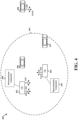
- negative feedback from distant UEs may cause the transmitting UE 402 to retransmit the message and may degrade the overall system performance.
- the receiving UE may be at a distance from the transmitting UE 402 such that the receiving UE will not be expected to correctly receive the message.
- Such retransmissions would degrade overall system performance through an inefficient use of wireless resources and through unnecessary potential interference to other wireless communication.
- the measured signal strength may include a Received Signal Strength Indicator (RSSI) and/or a Reference Signal Received Power (RSRP).
- RSSI Received Signal Strength Indicator
- RSRP Reference Signal Received Power
- the signal strength may be measured based on a control portion of the message.
- the signal strength may be measured based on a data portion of the message.
- the signal strength may be measured based on both a data portion of the message and a control portion of the message.
- the corresponding signal strength threshold for providing feedback for messages of the service group may be also configured.
- the measured signal strength threshold may be included in the control information of the V2X message 416 itself.
- the measured signal strength threshold may be dynamically adjustable.
- the transmitting UE 402 may adjust the intended range by dynamically adjusting the threshold per transmission.
- the message may comprise an Information Element (IE) associated with a group ID information for the service group.
- the message may comprise an IE that is generated as a hash of group ID information for the service group and the indication of the signal strength threshold parameter.
- the message may comprise both an IE that is generated as a hash of group ID information for the service group and an IE that contains the indication of the signal strength threshold parameter.
- the transmitting UE 402 may hash the group ID + extra information into the IE which provides a shorter identifier that can be embedded in the control portion of the message 416.
- the use of the IE may reduce the overhead burden of the message while providing the group ID information and the additional information for the signal strength parameter used to determine whether to send feedback.
- the extra information may indicate the RSSI/RSRP threshold.
- the extra information may indicate information, e.g., at least one parameter, that can be used by the UE to determine the RSSI/RSSP threshold.
- the transmitting UE 402 may hash the group ID into the IE which provides a shorter identifier, and may include both this IE and the extra information in the message 416.
- the receiving UE 404, 406, 408, or 410 may determine to send the feedback (e.g., a ACK or a NACK 424) if the signal strength that is measured for the message meets a threshold or is within a range.
- the receiving UE may transmit negative HARQ feedback (e.g., a NACK) to the transmitting UE 402 if the message 416 is not correctly received and the signal strength of a measured portion of the message meets the threshold signal strength or is within a range of signal strengths.
- the receiving UE may transmit positive HARQ feedback (e.g., an ACK) to the transmitting UE 402 if the message is correctly received and the signal strength of a measured portion of the message meets the threshold signal strength or is within a range of signal strengths.
- positive HARQ feedback e.g., an ACK
- the receiving UE may determine to refrain from sending the feedback to the transmitting UE 402, regardless of whether the packet is received correctly or not.
- the UE might not send a NACK even if the message is incorrectly received and might not send an ACK even if the message is correctly received.
- the transmitting UE 402 may be configured to determine the intended range for the service group and to transmit the message 416 for the service group based, at least in part, on the determined range. For example, the transmitting UE 402 may provide the indication 418 of the parameter for the signal strength threshold associated with the service group.
- the signal strength threshold may be used by receiving UEs 404, 406, 408, or 410 to determine whether to send the feedback to the message.
- the indication 418 of the parameter may be comprised in the message 416.
- UEs within proximity of the transmitting UE 402 may send the feedback, and distant UEs (e.g., outside the intended area/range 401) may avoid sending feedback, thereby increasing the performance and reliability of the overall system.
- the transmitting UE 402 may control retransmission attempts based on a signal strength of NACK received from one or more receiving UEs. For example, a retransmission component 498 of the transmitting UE 402 may determine whether to retransmit a message based on a signal strength of the received feedback. In the example in FIG. 4 , the transmitting UE 402 may multicast the message 416 to the service group and receive HARQ feedback from at least one receiving UE. The transmitting UE 402 may measure a signal strength for the HARQ feedback, and determine whether to resend the message (e.g., as retransmission 416') based on the measured signal strength for the HARQ feedback.
- a retransmission component 498 of the transmitting UE 402 may determine whether to retransmit a message based on a signal strength of the received feedback.
- the transmitting UE 402 may multicast the message 416 to the service group and receive HARQ feedback from at least one receiving UE.
- the transmitting UE 402 may assess the signal strength of the combined NACK feedback in the common resource in order to determine whether to retransmit the message. In some aspects, the transmitting UE 402 may determine to resend the message if the signal strength measured for the negative HARQ feedback meets a second threshold, then the transmitting UE 402 may resend the message for the service group. When the signal strength of the combined NACK is above the second threshold, it may indicate that multiple receiving UEs did not receive the message correctly or may indicate that at least one UE within the intended range of the message did not receive the message correctly. On the other hand, the transmitting UE 402 may determine to refrain from resending the message if the signal strength measured for the negative HARQ feedback is below the second threshold.
- the transmitting UE 402 may avoid wasting wireless resources by limiting retransmissions of the message, thereby increasing the efficiency and reliability of the overall system.
- the transmitting UE 402 may determine the received strength of the NACK from receiving UEs. If the RSSI / RSRP of the NACK exceeds a second threshold, then the transmitting UE 402 may decide to retransmit.
- the second threshold may be based on at least one of an intended range for the message and/or a QoS requirement for the message. When multiple receiving UEs in a desired range do not receive the message, the combined signal strength of the NACKs may be higher than when one or two UEs do not receive the message. If the signal strength measured for the HARQ feedback exceeds the second threshold, which may indicate multiple receiving UEs in desired range do not receive the message, rather than one or two receiving UEs not receiving the message. In this way, the transmitting UE 402 may retransmit the message when multiple receiving UEs in desired range do not receive the message, and may avoid unnecessary retransmitting.
- the method may help to avoid retransmissions to a receiving device that may be too distant to correctly receive a message.
- the method may help reduce system degradation due to such retransmissions, and therefore, may improve the efficient use of wireless resources.
- the method may also help to avoid reception of feedback from unintended receiving devices that are a part of a service group yet are not proximate to a transmitting device.
- the transmitting device 502 may transmit a message for the service group.
- the transmitting device may multicast the message to the service group.
- the transmitting device 502 may provide an indication of a parameter for a first signal strength threshold associated with the service group, where the first signal strength threshold may be used by the receiving device 504 to determine whether to send feedback to the message.
- the receiving device 504 may determine a first signal strength threshold based on the indication of the parameter, where the parameter may be an explicit indication of the first signal strength threshold or a QoS parameter associated with the service group from which the first signal strength threshold may be determined.
- the message may not contain an indication of the parameter.
- the receiving device 504 may determine the signal strength threshold, e.g., based on a QoS associated with the service group or based on other information. For example, the receiving device 504 may determine the signal strength threshold based on previously received or preconfigured information. The signal strength threshold may be preconfigured at the receiving device. The receiving device 504 may receive, from the transmitting device 502, at least a portion of the message for the service group.
- the receiving device 504 may measure a signal strength for the message received from the transmitting device 502.
- the signal strength measured for the HARQ feedback may comprise at least one of an RSSI and/or RSRP.
- the receiving device 504 may determine whether to send feedback to the transmitting device 502 based on the signal strength measured for the message. If the measured signal strength is below the threshold, the receiving device 504 may determine that it does not need to send feedback regardless of whether the message is correctly received.
- the receiving device 504 may send feedback to the transmitting device 502. For example, the receiving device 504 may determine to send the feedback if the signal strength measured for the message meets a first threshold. For example, the receiving device 504 may transmit negative HARQ feedback to the transmitting device 502 if the message is not correctly received. In another example, the receiving device 504 may transmit positive feedback if the message is received correctly. The transmitting device 502 may receive the HARQ feedback from the receiving device 504.
- the transmitting device 502 may measure a signal strength for the HARQ feedback.
- the transmitting device 502 may determine whether to resend the message based on the signal strength measured for the HARQ feedback. For example, when the HARQ feedback comprises negative HARQ feedback, the transmitting device 502 may determine to resend the message, e.g., in retransmission 528, if the signal strength measured for the negative HARQ feedback meets a second threshold, then the transmitting device 502 may resend the message for the service group. For example, the transmitting device 502 may determine to refrain from resending the message if the signal strength measured for the negative HARQ feedback is below the second threshold.
- the transmitting device 502 may determine to refrain from resending the message if the signal strength measured for the negative HARQ feedback is below the second threshold.
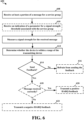
- FIG. 6 is a flowchart 600 of a method of wireless communication at a receiving device.
- the method may be performed, for example, by a receiving UE or a component of a UE (e.g., UE 104, 404, 1050; receiving device 504; the apparatus 702/702'; the processing system 814, which may include memory and which may be an entire UE or a component of a UE).
- the apparatus may communicate with a transmitting device (e.g., transmitting UE 402, transmitting device 502).
- the apparatus may comprise an RSU 107, or a component of an RSU 107, a base station 102, 180 or component of a base station engaged in PC5 communication.
- the wireless communication may comprise D2D communication, such as V2X communication, V2V communication, or other D2D communication, as described herein.
- D2D communication such as V2X communication, V2V communication, or other D2D communication, as described herein.
- the method of flowchart 600 may be discussed with reference to the examples illustrated in FIGS. 4 and 5 .
- Optional aspects may be illustrated in dashed lines. Aspects presented herein may help to limit feedback to intended receiving devices, e.g., to devices that are part of a service group and that are within an intended range of the transmitting device.
- the method may help to avoid triggering transmissions at a transmitting device to a receiving device that may be too distant to correctly receive a message.
- the method may help reduce system degradation due to such retransmissions, and therefore, may improve the efficient use of wireless resources.
- the method may also help to avoid feedback from unintended receiving devices that are a part of a service group yet are not proximate to a transmitting device
- the message may include an information element based on a hash of a group ID for the service group and the parameter for the signal strength threshold. For example, if the transmitting device (e.g., the multicast sender) is to send a group ID plus a limited set of extra information, the transmitting device may hash the group ID + extra information into an information element (e.g., a shorter identifier) that is embedded in the control portion of the message.
- the extra information may include the RSSI/RSRP threshold or a parameter that enables the receiving device to determine the RSSI/RSRP threshold.
- the receiving device may determine whether the receiving device is within a range of the transmitting device based on the measured signal strength for the received message.
- the range may be based on a distance from the transmitting device in which receiving devices are intended to correctly receive the message.
- the determination may be performed, e.g., by range component 714 of apparatus 702.
- the receiving device may compare the measured signal strength (e.g., RSSI/RSRP) with a threshold, to determine if the receiving device is the "intended" receiver or not.
- the threshold may be based on an intended range for the received message.
- the achieved range/distance by the transmitting device e.g., sender
- the RSSI/RSRP threshold may be mapped from the QoS parameter, 5QI, range, etc. for the received message.
- the RSSI/RSRP threshold may be based at least in part on the QoS parameter.
- the QoS parameter may be a "stand-alone" range parameter, or 5QI which incorporates range requirement.
- the receiving device may use more than one threshold, e.g., an upper threshold and a lower threshold to determine whether the UE is within an intended range. For example, the receiving device may determine whether the measured signal strength is within a signal strength range having an upper bound and a lower bound.
- the receiving device may determine whether to send a feedback to the transmitting device based on the signal strength measured for the received message. For example, the receiving device may determine to send feedback to the transmitting device when the receiving device is within the range of the transmitting device, e.g., an intended range for accurate reception of the message.
- the feedback may include HARQ feedback.
- the determination may be performed, e.g., by determination component 710 of apparatus 702.
- the receiving device may determine to send the feedback if the signal strength measured for the received message meets the threshold. When the measured signal strength meets a threshold signal strength, it may be an indication that the receiving device is within an intended range of the transmitting device. Therefore, the receiving device may determine that it should send feedback to the transmitting device.
- the receiving device may determine whether the message is received correctly, as illustrated at 618. In other examples, the determination about whether the message is received correctly may be made prior to determining the measured signal strength. The determination may be performed, e.g., by determination component 710 of apparatus 702.
- the receiving UE may use a delta in connection with the transmission power at which the message was transmitted to determine whether the receiving UE is an intended receiver and/or whether to send feedback.
- the receiving UE may also use other parameters to determine whether to send feedback. For example, the receiving UE may use parameters received in a control message (e.g., sidelink control information SCI).
- the receiving UE may use a current interference level of the receiving UE, a channel busy ratio (CBR) of the receiving UE, etc. to determine whether to send feedback
- CBR channel busy ratio
- the receiving device may transmit negative HARQ feedback (e.g., a NACK) to the transmitting device if the message is not correctly received, as illustrated at 622.
- the receiving device may transmit positive HARQ feedback (e.g., an ACK) to the transmitting device if the message is correctly received, as illustrated at 620.
- the feedback may be transmitted, e.g., by feedback component 712 of apparatus 702.
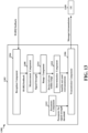
- FIG. 7 is a conceptual data flow diagram 700 illustrating the data flow between different means/components in an example apparatus 702.
- the apparatus may be a receiving device or a component of a receiving device that receives wireless communication from a transmitting device.
- the apparatus may comprise a UE 104 or a component of a UE, an RSU 107 or a component of an RSU, or a base station 102, 180 or component of a base station engaged in PC5 communication.
- the wireless communication may comprise a V2X, V2V, or other D2D communication, as described herein.
- the apparatus includes a determination component 710 configured to determine whether to send feedback to the transmitting device based on the signal strength measured for the received message, e.g., as described in connection with 614 and/or 618 of FIG. 6 .
- the apparatus includes a feedback component 712 configured to transmit a HARQ feedback, via a transmission component 706, to the transmitting device, e.g., as described in connection with 620 and/or 622 of FIG. 6 .
- the apparatus may include additional components that perform each of the blocks of the algorithm in the aforementioned flowcharts of FIGs. 4-6 .
- each block in the aforementioned flowcharts of FIGs. 4-6 may be performed by a component and the apparatus may include one or more of those components.
- the components may be one or more hardware components specifically configured to carry out the stated processes/algorithm, implemented by a processor configured to perform the stated processes/algorithm, stored within a computer-readable medium for implementation by a processor, or some combination thereof.
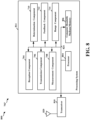
- FIG. 8 is a diagram 800 illustrating an example of a hardware implementation for an apparatus 702' employing a processing system 814.
- the processing system 814 may be implemented with a bus architecture, represented generally by the bus 824.
- the bus 824 may include any number of interconnecting buses and bridges depending on the specific application of the processing system 814 and the overall design constraints.
- the bus 824 links together various circuits including one or more processors and/or hardware components, represented by the processor 804, the components 704, 706, 708, 710, 712, 714 and the computer-readable medium/memory 806.
- the bus 824 may also link various other circuits such as timing sources, peripherals, voltage regulators, and power management circuits, which are well known in the art, and therefore, will not be described any further.
- the aforementioned means may be one or more of the aforementioned components of the apparatus 702 and/or the processing system 814 of the apparatus 702' configured to perform the functions recited by the aforementioned means.
- the processing system 814 may include the TX Processor 368, the RX Processor 356, and the controller/processor 359.
- the aforementioned means may be the TX Processor 368, the RX Processor 356, and the controller/processor 359 configured to perform the functions recited by the aforementioned means.
- FIG. 9 is a flowchart 900 of a method of wireless communication at a transmitting device.
- the transmitting device may comprise a UE 104 or a component of a UE, an RSU 107 or a component of an RSU, or a base station 102, 180 or component of a base station, e.g., engaged in PC5 communication.
- the method may be performed, for example, by a transmitting UE 402; transmitting device 502; the apparatus 1002/1002'; the processing system 1114, which may include memory and which may be an entire UE or a component of a UE.
- the wireless communication may comprise D2D communication, such as V2X communication, V2V communication, or other D2D communication.
- the method of flowchart 900 may be discussed with reference to the examples illustrated in FIGS. 4 and 5 .
- Optional aspects may be illustrated in dashed lines. Aspects presented herein may help to limit feedback to avoid retransmissions to a receiving device that may be too distant to correctly receive a message.
- the method may help reduce system degradation due to such retransmissions, and therefore, may improve the efficient use of wireless resources.
- the method may also help to avoid reception of feedback from unintended receiving devices that are a part of a service group yet are not proximate to a transmitting device.
- the transmitting device determines an intended range for the service group.
- the intended range may correspond to a distance from the transmitting device in which receiving device are intended to correctly receive a message.
- the intended range may be determined, e.g., based on a QoS profile associated with the service group, e.g., a 5QI. The determination may be performed, e.g., by determination component 1008 of apparatus 1002.
- the transmitting device may transmit a message for the service group based, at least in part, on the determined range.
- the message may comprise a V2X message or a D2D message, for example.
- the message may be transmitted, e.g., by transmission component 1006 of apparatus 1002.
- the message may include a control portion and a data portion.
- the transmitting device may provide a parameter for the signal strength threshold associated with the service group, as illustrated at 912.
- the transmitting device may provide the signal strength threshold itself as the parameter or may provide a parameter that enables the receiving device to determine the signal strength threshold.
- the parameter may be provided, e.g., by IE component 1010 and/or indication component 1014, via transmission component 1006 of apparatus 1002.
- the parameter may assist receiving devices in determining a signal strength threshold in order to determine whether to send the feedback to the message.
- the parameter may help the transmitting device to receive limited feedback from receivers within an intended area.
- the parameter may include a QoS parameter associated with a service group.
- the parameter provides information that enables receiving devices to determine whether they are an intended receiver, e.g., based on proximity through the signal strength threshold.
- the parameter may be comprised in the message.
- the message may further comprise an information element associated with a group ID for the service group.
- the group ID may be provided, e.g., by group ID component 1012 of apparatus 1002.
- the transmitting device may hash the group ID with the parameter to generate the information element, as illustrated at 914.
- the apparatus may include additional components that perform each of the blocks of the algorithm in the aforementioned flowcharts of FIGs. 4 , 5 and 9 .
- each block in the aforementioned flowcharts of FIGs. 4 , 5 and 9 may be performed by a component and the apparatus may include one or more of those components.
- the components may be one or more hardware components specifically configured to carry out the stated processes/algorithm, implemented by a processor configured to perform the stated processes/algorithm, stored within a computer-readable medium for implementation by a processor, or some combination thereof.
- the processing system 1114 may be coupled to a transceiver 1110.
- the transceiver 1110 is coupled to one or more antennas 1120.
- the transceiver 1110 provides a means for communicating with various other apparatus over a transmission medium.
- the transceiver 1110 receives a signal from the one or more antennas 1120, extracts information from the received signal, and provides the extracted information to the processing system 1114, specifically the reception component 1004.
- the transceiver 1110 receives information from the processing system 1114, specifically the transmission component 1006, and based on the received information, generates a signal to be applied to the one or more antennas 1120.
- the processing system 1114 includes a processor 1104 coupled to a computer-readable medium/memory 1106.
- the processor 1104 is responsible for general processing, including the execution of software stored on the computer-readable medium/memory 1106.
- the software when executed by the processor 1104, causes the processing system 1114 to perform the various functions described supra for any particular apparatus.
- the computer-readable medium / memory 1106 may also be used for storing data that is manipulated by the processor 1104 when executing software.
- the processing system 1114 further includes at least one of the components 1004, 1006, 1008, 1010, 1012, 1014.
- the components may be software components running in the processor 1104, resident/stored in the computer readable medium/memory 1106, one or more hardware components coupled to the processor 1104, or some combination thereof.
- the processing system 1114 may be a component of device 350 and may include the memory 360 and/or at least one of the TX processor 368, the RX processor 356, and the controller/processor 359.
- the processing system 814 may comprise the entire device 350, e.g., an entire UE.
- the apparatus 1002/1002' for wireless communication includes means for determining an intended range for a service group.
- the apparatus may include means for transmitting a message for the service group based, at least in part, on the determined range.
- the apparatus may include means for providing a parameter for a signal strength threshold associated with the service group.
- the apparatus may include means for hashing a group ID and/or parameter in order to generate an IE.
- the aforementioned means may be one or more of the aforementioned components of the apparatus 1002 and/or the processing system 1114 of the apparatus 1002' configured to perform the functions recited by the aforementioned means.
- the processing system 1114 may include the TX Processor 368, the RX Processor 356, and the controller/processor 359.
- the aforementioned means may be the TX Processor 368, the RX Processor 356, and the controller/processor 359 configured to perform the functions recited by the aforementioned means.
- FIG. 12 is a flowchart 1200 of a method of wireless communication at a transmitting device.
- the transmitting device may comprise a UE 104, a component of a UE 104, an RSU 107, a component of an RSU 107, a base station 102, 180, or component of a base station, e.g., engaged in PC5 communication.
- the method may be performed, for example, by transmitting UE 402; transmitting device 502; the apparatus 1002/1002'; the processing system 1114, which may include memory and which may be an entire UE or a component of a UE.
- the wireless communication may comprise D2D communication, such as V2X communication, V2V communication, or other D2D communication.
- the method of flowchart 1200 may be discussed with reference to the examples illustrated in FIGS. 4 and 5 .
- Optional aspects may be illustrated in dashed lines. Aspects presented herein may help to limit retransmissions to avoid retransmissions to a receiving device that may be too distant to correctly receive a message.
- the method may help reduce system degradation due to such retransmissions, and therefore, may improve the efficient use of wireless resources.
- the method may also help to avoid reception of feedback from unintended receiving devices that are a part of a service group yet are not proximate to a transmitting device.
- the transmitting device may determine whether the HARQ feedback is from receiving device(s) within the intended range and/or whether the combined signal strength meets a threshold. The determination may be based on the signal strength measured for the HARQ feedback. For example, a signal strength that meets the threshold may indicate that at least one receiving device is within the intended range of the transmitting device. The determination may be performed, e.g., by range component 1314 of apparatus 1302.
- the transmitting device may use the measurement to determine whether to resend the message based on the signal strength measured for the HARQ feedback. For example, the transmitting device may determine to resend the message when the HARQ feedback is from receiving device(s) within the intended range or when the measured signal strength meets a threshold signal strength level. The determination may be performed, e.g., by determination component 1310 of apparatus 1302.
- the HARQ feedback may be received in a common resource in time and frequency.
- the HARQ feedback may comprise combined feedback from one or more receiving devices.
- the transmitting device may determine the received strength of the NACK from receiving device(s). If the RSSI / RSRP of the NACK exceeds a threshold, then the transmitting device may decide to retransmit.
- the threshold may be based on at least one of an intended range for the message or a quality of service for the message.
- the apparatus includes a transmission component 1306 configured to transmit (e.g., multicast) a message to a service group, e.g., as described in connection with 1208 in FIG. 12 .
- the apparatus includes a reception component 1304 that receives HARQ feedback from at least one receiving device.
- the apparatus includes a measurement component 1308 configured to measure a signal strength for the HARQ feedback, e.g., as described in connection with 1212 in FIG. 12 .
- the apparatus may include a range component 1314 configured to determine whether the HARQ feedback is from a receiving device within the intended range based on the signal strength measured for the HARQ feedback.
- the apparatus includes a determination component 1310 configured to determine whether to resend the message based on the signal strength measured for the HARQ feedback, e.g., as described in connection with 1214 in FIG. 12 .
- the transmitting device may determine to resend the message if the signal strength measured for the negative HARQ feedback meets a second threshold, then the transmitting device may resend the message for the service group.
- the transmitting device may determine to refrain from resending the message if the signal strength measured for the negative HARQ feedback is below the second threshold.
- the second threshold may be based on at least one of an intended range for the message, or a quality of service for the message, or a combination of the intended range and the quality of service.
- the apparatus may include a parameter component 1312 configured to provide a parameter for a signal strength threshold to receiving device(s) 1350.
- the processor 1404 is responsible for general processing, including the execution of software stored on the computer-readable medium/memory 1406.
- the software when executed by the processor 1404, causes the processing system 1414 to perform the various functions described supra for any particular apparatus.
- the computer-readable medium / memory 1406 may also be used for storing data that is manipulated by the processor 1404 when executing software.
- the processing system 1414 further includes at least one of the components 1304, 1306, 1308, 1310, 1312, 1314.
- the components may be software components running in the processor 1404, resident/stored in the computer readable medium/memory 1406, one or more hardware components coupled to the processor 1404, or some combination thereof.
- the processing system 1414 may be a component of the device 350 and may include the memory 360 and/or at least one of the TX processor 368, the RX processor 356, and the controller/processor 359.
- the apparatus 1302/1302' for wireless communication includes means for multicasting a message to a service group for an intended range.
- the apparatus may include means for receiving HARQ feedback from at least one RX UE.
- the apparatus may include means for measuring a signal strength for the HARQ feedback.
- the apparatus may include means for determining whether the HARQ feedback is from a receiving device within the intended range based on the signal strength measured for the HARQ feedback.
- the apparatus may include means for determining to resend the message based on the signal strength measured for the HARQ feedback.
- the aforementioned means may be one or more of the aforementioned components of the apparatus 1302 and/or the processing system 1414 of the apparatus 1302' configured to perform the functions recited by the aforementioned means.
- the processing system 1414 may include the TX Processor 368, the RX Processor 356, and the controller/processor 359.
- the aforementioned means may be the TX Processor 368, the RX Processor 356, and the controller/processor 359 configured to perform the functions recited by the aforementioned means.
- Combinations such as "at least one of A, B, or C,” “one or more of A, B, or C,” “at least one of A, B, and C,” “one or more of A, B, and C,” and "A, B, C, or any combination thereof” include any combination of A, B, and/or C, and may include multiples of A, multiples of B, or multiples of C.
- combinations such as “at least one of A, B, or C,” “one or more of A, B, or C,” “at least one of A, B, and C,” “one or more of A, B, and C,” and “A, B, C, or any combination thereof” may be A only, B only, C only, A and B, A and C, B and C, or A and B and C, where any such combinations may contain one or more member or members of A, B, or C.
- nothing disclosed herein is intended to be dedicated to the public regardless of whether such disclosure is explicitly recited in the claims.
Landscapes
- Engineering & Computer Science (AREA)
- Computer Networks & Wireless Communication (AREA)
- Signal Processing (AREA)
- Quality & Reliability (AREA)
- Physics & Mathematics (AREA)
- Electromagnetism (AREA)
- Mobile Radio Communication Systems (AREA)
Claims (15)
- Ein Verfahren zur drahtlosen Kommunikation an einer Empfangsvorrichtung, das Folgendes aufweist:Empfangen, von einer Sendevorrichtung, von zumindest einem Teil einer Nachricht für eine Dienstgruppe, wobei die Nachricht eine Vorrichtung-zu-Vorrichtung- bzw. D2D-Nachricht (D2D = device-to-device) aufweist (608);Messen einer Signalstärke für die empfangene Nachricht (612);Bestimmen, ob sich die Empfangsvorrichtung innerhalb einer Reichweite der Sendevorrichtung befindet, basierend auf der gemessenen Signalstärke für die empfangene Nachricht (613); undBestimmen eine HARQ-Rückmeldung an die Sendevorrichtung zu senden, wenn sich die Empfangsvorrichtung innerhalb der Reichweite der Sendevorrichtung befindet (614).
- Das Verfahren gemäß Anspruch 1, das eines der folgenden aufweist:i) wobei die für die empfangene Nachricht gemessene Signalstärke zumindest eines aus einem Empfangssignalstärkeindikator, RSSI (RSSI = Received Signal Strength Indicator), einer Referenzsignalempfangsleistung, RSRP (RSRP = Reference Signal Received Power) oder einer Kombination aus RSSI und RSRP aufweist;ii) wobei die Signalstärke für die empfangene Nachricht basierend auf zumindest einem gemessen wird:einem Steuerteil der empfangenen Nachricht;einem Datenteil der empfangenen Nachricht; odereiner Kombination aus dem Steuerteil der empfangenen Nachricht unddem Datenteil der empfangenen Nachricht;iii) wobei die Empfangsvorrichtung bestimmt die Rückmeldung zu senden, wenn die für die empfangene Nachricht gemessene Signalstärke einen Schwellenwert erreicht.
- Das Verfahren gemäß Anspruch 2, Option iii), das weiter eines der folgenden aufweist:i) Senden einer negativen HARQ-Rückmeldung (HARQ = Hybrid Automatic Repeat Request bzw. "hybride automatische Wiederholungsanforderung") an die Sendevorrichtung, wenn die empfangene Nachricht nicht korrekt empfangen wird (622); oder
Senden einer positiven HARQ-Rückmeldung an die Sendevorrichtung, wenn die empfangene Nachricht korrekt empfangen wird (620);ii) wobei, wenn die für die empfangene Nachricht gemessene Signalstärke unter dem Schwellenwert liegt, die Empfangsvorrichtung bestimmt, von einem Senden der Rückmeldung abzusehen (616);iii) wobei der Schwellenwert auf einem Dienstqualitätsparameter basiert;iv) wobei der Schwellenwert auf einer beabsichtigten Reichweite für die empfangene Nachricht basiert;v) wobei der Schwellenwert an der Empfangsvorrichtung konfiguriert wird;vi) weiter aufweisend:
Empfangen eines Parameters von der Sendevorrichtung, wobei der Schwellenwert zumindest teilweise auf dem Parameter basiert. - Das Verfahren gemäß Anspruch 3, Option vi), wobei der Parameter in der empfangenen Nachricht enthalten ist.
- Das Verfahren gemäß Anspruch 4, wobei die empfangene Nachricht weiter eine Gruppenidentifizierer-Information bzw. ID-Information (ID = identifier) für die Dienstgruppe aufweist.
- Das Verfahren gemäß Anspruch 5, wobei die empfangene Nachricht ein Informationselement, IE (IE = information element), aufweist, das einen Hash eines Gruppen-ID für die Dienstgruppe und den Parameter aufweist, oder ein erstes IE, das einen Hash des Gruppen-ID für die Dienstgruppe aufweist, und ein zweites IE aufweist, das den Parameter aufweist.
- Ein Verfahren zur drahtlosen Kommunikation an einer Sendevorrichtung, das aufweist:Senden einer Nachricht an eine Dienstgruppe für eine beabsichtigte Reichweite (1208), wobei die Nachricht eine Vorrichtung-zu-Vorrichtung- bzw. D2D-Nachricht (D2D = device-to-device) aufweist;Empfangen einer HARQ-Rückmeldung (HARQ = Hybrid Automatic Repeat Request bzw. "hybride automatische Wiederholungsanforderung") (1210) von zumindest einer Empfangsvorrichtung;Messen einer Signalstärke für die HARQ-Rückmeldung (1212);Bestimmen, ob die HARQ-Rückmeldung von einer Empfangsvorrichtung innerhalb der beabsichtigten Reichweite ist (1213), basierend auf der für die HARQ-Rückmeldung gemessenen Signalstärke; undBestimmen, die Nachricht erneut zu senden, wenn die HARQ-Rückmeldung von der Empfangsvorrichtung innerhalb der beabsichtigten Reichweite ist (1214).
- Das Verfahren gemäß Anspruch 7:i) wobei die Signalstärke für eine kombinierte HARQ-Rückmeldung in einer gemeinsamen Ressource gemessen wird; oderii) wobei die HARQ-Rückmeldung eine negative HARQ-Rückmeldung aufweist, wobei die Sendevorrichtung bestimmt, die Nachricht erneut zu senden, wenn die für die negative HARQ-Rückmeldung gemessene Signalstärke einen Schwellenwert erreicht.
- Das Verfahren gemäß Anspruch 8, Option ii), das weiter eines der folgenden aufweist:i) erneutes Senden der Nachricht für die Dienstgruppe (1218);ii) wobei die Sendevorrichtung bestimmt, von einem erneuten Senden der Nachricht abzusehen, wenn die für die negative HARQ-Rückmeldung gemessene Signalstärke unter dem Schwellenwert ist (1216); oderiii) wobei der Schwellenwert auf zumindest einem aus der beabsichtigten Reichweite für die Nachricht, einer Dienstqualität für die Nachricht oder einer Kombination aus der beabsichtigten Reichweite und der Dienstqualität basiert.
- Das Verfahren gemäß Anspruch 7:i) wobei die für die HARQ-Rückmeldung gemessene Signalstärke zumindest eines aus einem Empfangssignalstärkeindikator, RSSI (RSSI = Received Signal Strength Indicator), einer Referenzsignalempfangsleistung, RSRP (RSRP = Reference Signal Received Power) oder einer Kombination aufweist; oderii) weiter aufweist:
Vorsehen eines Parameters für einen Signalstärkeschwellenwert, der mit der Dienstgruppe assoziiert ist. - Eine Vorrichtung zur drahtlosen Kommunikation, die Folgendes aufweist:Mittel zum Empfangen, von einer Sendevorrichtung, von zumindest einem Teil einer Nachricht für eine Dienstgruppe, wobei die Nachricht eine Vorrichtung-zu-Vorrichtung- bzw. D2D-Nachricht (D2D = device-to-device) aufweist;Mittel zum Messen einer Signalstärke für die empfangene Nachricht, die von der Sendevorrichtung empfangen wird;Mittel zum Bestimmen, ob sich die Vorrichtung innerhalb einer Reichweite der Sendevorrichtung befindet, basierend auf der gemessenen Signalstärke für die empfangene Nachricht; undMittel zum Bestimmen, eine HARQ-Rückmeldung an die Sendevorrichtung zu senden, wenn sich die Vorrichtung innerhalb der Reichweite der Sendevorrichtung befindet.
- Die Vorrichtung gemäß Anspruch 11, die weiter Mittel zum Ausführen des Verfahrens gemäß einem der Ansprüche 2 bis 6 aufweist.
- Eine Vorrichtung zur drahtlosen Kommunikation, die Folgendes aufweist:Mittel zum Senden einer Nachricht an eine Dienstgruppe für eine beabsichtigte Reichweite, wobei die Nachricht eine Vorrichtung-zu-Vorrichtung- bzw. D2D-Nachricht (D2D = device-to-device) aufweist;Mittel zum Empfangen einer HARQ-Rückmeldung (HARQ = Hybrid Automatic Repeat Request bzw. "hybride automatische Wiederholungsanforderung") von zumindest einer Empfangsvorrichtung;Mittel zum Messen einer Signalstärke für die HARQ-Rückmeldung;Mittel zum Bestimmen, ob die HARQ-Rückmeldung von einer Empfangsvorrichtung innerhalb der beabsichtigten Reichweite ist, basierend auf der für die HARQ-Rückmeldung gemessenen Signalstärke; undMittel zum Bestimmen, die Nachricht erneut zu senden, wenn die HARQ-Rückmeldung von der Empfangsvorrichtung innerhalb der beabsichtigten Reichweite ist.
- Die Vorrichtung gemäß Anspruch 13, die weiter Mittel zum Ausführen des Verfahrens gemäß einem der Ansprüche 8 bis 10 aufweist.
- Ein computerlesbares Medium, das computerausführbaren Code zur drahtlosen Kommunikation an einer Empfangsvorrichtung speichert, wobei der Code bei Ausführung durch den Prozessor den Prozessor dazu veranlasst, das Verfahren gemäß einem der Ansprüche 1 bis 10 auszuführen.
Priority Applications (1)
| Application Number | Priority Date | Filing Date | Title |
|---|---|---|---|
| EP25162278.3A EP4546942A3 (de) | 2018-09-26 | 2019-09-25 | Kommunikation auf basis von funksignalmessungen |
Applications Claiming Priority (3)
| Application Number | Priority Date | Filing Date | Title |
|---|---|---|---|
| US201862737081P | 2018-09-26 | 2018-09-26 | |
| US16/581,699 US12538343B2 (en) | 2018-09-26 | 2019-09-24 | Communication based on radio signal measurements |
| PCT/US2019/052875 WO2020068924A2 (en) | 2018-09-26 | 2019-09-25 | Communication based on radio signal measurements |
Related Child Applications (2)
| Application Number | Title | Priority Date | Filing Date |
|---|---|---|---|
| EP25162278.3A Division EP4546942A3 (de) | 2018-09-26 | 2019-09-25 | Kommunikation auf basis von funksignalmessungen |
| EP25162278.3A Division-Into EP4546942A3 (de) | 2018-09-26 | 2019-09-25 | Kommunikation auf basis von funksignalmessungen |
Publications (2)
| Publication Number | Publication Date |
|---|---|
| EP3857767A2 EP3857767A2 (de) | 2021-08-04 |
| EP3857767B1 true EP3857767B1 (de) | 2025-04-16 |
Family
ID=69883815
Family Applications (2)
| Application Number | Title | Priority Date | Filing Date |
|---|---|---|---|
| EP25162278.3A Pending EP4546942A3 (de) | 2018-09-26 | 2019-09-25 | Kommunikation auf basis von funksignalmessungen |
| EP19783882.4A Active EP3857767B1 (de) | 2018-09-26 | 2019-09-25 | Kommunikation auf basis von funksignalmessungen |
Family Applications Before (1)
| Application Number | Title | Priority Date | Filing Date |
|---|---|---|---|
| EP25162278.3A Pending EP4546942A3 (de) | 2018-09-26 | 2019-09-25 | Kommunikation auf basis von funksignalmessungen |
Country Status (4)
| Country | Link |
|---|---|
| US (1) | US12538343B2 (de) |
| EP (2) | EP4546942A3 (de) |
| CN (2) | CN118740337A (de) |
| WO (1) | WO2020068924A2 (de) |
Families Citing this family (12)
| Publication number | Priority date | Publication date | Assignee | Title |
|---|---|---|---|---|
| US12490045B2 (en) | 2018-09-26 | 2025-12-02 | Qualcomm Incorporated | Transmission with indication of geographic area |
| WO2020091211A1 (ko) * | 2018-11-01 | 2020-05-07 | 엘지전자 주식회사 | Nr v2x에서 harq 피드백을 결정하기 위한 임계치를 조정하는 방법 및 장치 |
| WO2020194049A1 (en) * | 2019-03-22 | 2020-10-01 | Lenovo (Singapore) Pte. Ltd. | Aggregating harq feedback |
| CN111865509B (zh) * | 2019-04-30 | 2022-04-29 | 华为技术有限公司 | 一种通信方法和装置 |
| CN113632544A (zh) * | 2019-08-16 | 2021-11-09 | Oppo广东移动通信有限公司 | 链路切换的方法和通信设备 |
| CN114731194B (zh) * | 2019-11-06 | 2025-06-20 | 瑞典爱立信有限公司 | 无线通信网络中的改进的重传处理 |
| US12266294B2 (en) * | 2019-11-08 | 2025-04-01 | Boe Technology Group Co., Ltd. | Display control method and device, display system, electronic device, and storage medium |
| EP4138319B1 (de) * | 2020-08-06 | 2025-04-16 | Guangdong Oppo Mobile Telecommunications Corp., Ltd. | Verfahren und vorrichtung zur rückkopplung von hybriden automatischen neuübertragungsanfragen, endgerät und netzwerkvorrichtung |
| CN113473264A (zh) * | 2021-07-19 | 2021-10-01 | 科舸物联科技有限公司 | 一种水表通信方法、装置、设备和计算机可读存储介质 |
| WO2023077428A1 (en) * | 2021-11-05 | 2023-05-11 | Qualcomm Incorporated | Inter-ue coordination details |
| WO2023220915A1 (en) * | 2022-05-17 | 2023-11-23 | Qualcomm Incorporated | Techniques for signal strength monitoring |
| US12495453B2 (en) * | 2022-10-19 | 2025-12-09 | Toyota Motor Engineering & Manufacturing North America, Inc. | Systems and methods for efficiently establishing peer-to-peer connections |
Family Cites Families (82)
| Publication number | Priority date | Publication date | Assignee | Title |
|---|---|---|---|---|
| US7089264B1 (en) | 2001-06-22 | 2006-08-08 | Navteq North America, Llc | Geographic database organization that facilitates location-based advertising |
| US8582593B2 (en) | 2009-12-29 | 2013-11-12 | Nokia Corporation | Multicast transmission within a hybrid direct and cellular communication system |
| KR20110135571A (ko) | 2010-06-11 | 2011-12-19 | 삼성전자주식회사 | 통신 시스템에서 멀티캐스트 자원 할당 정보 송/수신 방법 및 장치 |
| US9363782B2 (en) | 2011-06-22 | 2016-06-07 | Qualcomm Incorporated | Methods and apparatus for wireless device positioning in multicarrier configurations |
| US9166764B2 (en) | 2012-10-16 | 2015-10-20 | Qualcomm Incorporated | Methods and apparatus for feedback computation and decoding with synchronously coded subcarriers in OFDMA systems |
| WO2014182039A1 (ko) | 2013-05-06 | 2014-11-13 | 엘지전자 주식회사 | 무선 통신 시스템에서 수신확인응답 전송 방법 및 장치 |
| US20150011230A1 (en) | 2013-07-08 | 2015-01-08 | Electronics & Telecommunications Research Institute | Method for communication based on coordinator in wireless communication system and apparatus for the same |
| US9107041B2 (en) | 2013-08-07 | 2015-08-11 | Alcatel Lucent | Systems and methods for determining a user equipment location based on measurements from multiple base stations |
| CN108924960B (zh) | 2014-01-24 | 2022-09-06 | 索尼公司 | 用于进行设备到设备通信的用户设备、基站和方法 |
| CN104936165A (zh) | 2014-03-20 | 2015-09-23 | 中兴通讯股份有限公司 | 一种网络覆盖状况检测方法、装置及系统 |
| US10716165B2 (en) | 2014-04-24 | 2020-07-14 | Lg Electronics Inc. | Methods and apparatus for releasing a sidelink radio bearer for D2D communication system |
| US10813068B2 (en) | 2014-05-08 | 2020-10-20 | Apple Inc. | Systems, methods, and devices for synchronization source selection for device-to-device communication |
| US10334591B2 (en) | 2014-05-27 | 2019-06-25 | Lg Electronics Inc. | Data transmission method and apparatus by device terminal in wireless communication system |
| US9961487B1 (en) | 2014-11-27 | 2018-05-01 | Guowang Miao | Methods and apparatus for enabling proximity services in mobile networks |
| US10743161B2 (en) | 2015-02-26 | 2020-08-11 | Samsung Electronics Co., Ltd. | Method for discriminating between unicast device to device(D2D) communication and groupcast D2D communication |
| CN104661177B (zh) | 2015-03-12 | 2018-05-15 | 深圳酷派技术有限公司 | 一种实现d2d通信的方法、系统及设备 |
| US10080185B2 (en) | 2015-04-10 | 2018-09-18 | Qualcomm Incorporated | Method and apparatus for securing structured proximity service codes for restricted discovery |
| CN107615844B (zh) | 2015-04-17 | 2021-11-09 | 松下电器(美国)知识产权公司 | 在侧行链路控制时段期间的多邻近服务组通信 |
| US10064212B2 (en) | 2015-05-14 | 2018-08-28 | Blackberry Limited | Transmitting a scheduling request for a device-to-device transmission |
| US9826460B2 (en) * | 2015-05-14 | 2017-11-21 | Qualcomm Incorporated | Measurement of D2D channels |
| US10681501B2 (en) | 2015-06-11 | 2020-06-09 | Lg Electronics Inc. | Method and apparatus for transmitting V2X message |
| US10075218B2 (en) | 2015-11-05 | 2018-09-11 | Samsung Electronics Co., Ltd. | Method and apparatus for FD-MIMO based multicasting in vehicular communication systems |
| KR102430874B1 (ko) * | 2015-11-25 | 2022-08-09 | 삼성전자주식회사 | 위치를 측정하기 위한 장치 및 방법 |
| WO2017103662A1 (en) | 2015-12-18 | 2017-06-22 | Bayerische Motoren Werke Ag | Method for transmitting a stream in a wireless network from a wireless communication device to a plurality of wireless communication devices with nack avoidance |
| EP3406103B1 (de) | 2016-01-22 | 2020-05-27 | Nec Corporation | Verfahren und vorrichtung zur übertragung von kollisionserkennung und -handhabung in einem fahrzeug-zu-allem-kommunikationssystem |
| WO2017146534A1 (en) | 2016-02-24 | 2017-08-31 | Lg Electronics Inc. | Method and apparatus for tracking location using v2x communication in a wireless communication system |
| WO2017155320A1 (ko) | 2016-03-09 | 2017-09-14 | 엘지전자 주식회사 | V2x 통신에서의 신호 송수신 방법 및 이를 위한 장치 |
| US10798673B2 (en) | 2016-04-01 | 2020-10-06 | Apple Inc. | Autonomous resource selection for vehicle-to-vehicle sidelink communications |
| WO2017171529A1 (ko) | 2016-04-01 | 2017-10-05 | 엘지전자 주식회사 | 무선 통신 시스템에서 단말에 의해 수행되는 v2x 전송 자원 선택 방법 및 상기 방법을 이용하는 단말 |
| US10757550B2 (en) | 2016-04-07 | 2020-08-25 | Lg Electronics Inc. | Method for performing sensing during terminal-specific sensing period in wireless communication system, and terminal using same |
| KR102362246B1 (ko) | 2016-07-22 | 2022-02-14 | 삼성전자주식회사 | 무선 통신 시스템에서 시스템 정보 획득을 위한 방법 및 시스템 |
| JP6810746B2 (ja) | 2016-08-10 | 2021-01-06 | 京セラ株式会社 | 通信装置、基地局及びネットワーク装置 |
| JP6718102B2 (ja) | 2016-08-10 | 2020-07-08 | 京セラ株式会社 | 無線端末 |
| US10855401B2 (en) | 2016-11-03 | 2020-12-01 | Lg Electronics Inc. | Method for determining retransmission numbers of sidelink data in wireless communication system and a device therefor |
| US10237874B2 (en) | 2016-11-03 | 2019-03-19 | Samsung Electronics Co., Ltd. | Method and apparatus for supporting vehicle to everything service |
| WO2018093220A1 (en) | 2016-11-18 | 2018-05-24 | Lg Electronics Inc. | Method and apparatus for transmitting information using v2x communication in a wireless communication system |
| KR102810029B1 (ko) * | 2016-11-30 | 2025-05-20 | 삼성전자 주식회사 | 무선 통신 시스템에서 데이터 송수신 방법 및 장치 |
| US10972913B2 (en) | 2016-12-23 | 2021-04-06 | Lg Electronics Inc. | Method for performing V2X communication in wireless communication system and device for same |
| CN114938533A (zh) | 2016-12-30 | 2022-08-23 | 英特尔公司 | 用于无线电通信的方法和设备 |
| US10638293B2 (en) | 2017-01-24 | 2020-04-28 | Apple Inc. | Discovery procedure for off grid radio service |
| US10659139B2 (en) | 2017-03-02 | 2020-05-19 | Lg Electronics Inc. | Method for user equipment (UE) to perform device-to-device (D2D) relay communication in wireless communication system and apparatus therefor |
| US11303392B2 (en) | 2017-03-16 | 2022-04-12 | Qualcomm Incorporated | Multi-HARQ methods and apparatus for codeblock group based transmissions |
| FI3603293T3 (fi) | 2017-03-23 | 2023-04-03 | Apple Inc | Priorisoitu viestinvälitys ja resurssin valinta ajoneuvojen välistä (v2v) sivuyhteysviestintää varten |
| EP3628133B1 (de) * | 2017-05-04 | 2024-01-10 | Koninklijke Philips N.V. | Intragruppe kommunikation |
| JP2020526149A (ja) | 2017-06-26 | 2020-08-27 | エルジー エレクトロニクス インコーポレイティド | 無線通信システムにおけるv2x通信のための端末の動作方法及び前記方法を利用する端末 |
| US11025374B2 (en) | 2017-08-04 | 2021-06-01 | Samsung Electronics Co., Ltd. | Methods and apparatus for resource allocation and feedback in vehicle to vehicle communication |
| US11147096B2 (en) | 2017-08-07 | 2021-10-12 | Lg Electronics Inc. | Method for transmitting and receiving signals in a wireless communication system and a device therefor |
| US10440687B2 (en) | 2017-08-10 | 2019-10-08 | Industrial Technology Research Institute | Method and user equipment for resource allocation of vehicle network |
| US10931426B2 (en) | 2017-08-10 | 2021-02-23 | Futurewei Technologies, Inc. | System and method for sidelink feedback |
| EP3451563A1 (de) | 2017-08-11 | 2019-03-06 | Industrial Technology Research Institute | Verfahren, sendeknoten und empfangsknoten zur rückkopplungssteuerung von nebenstreckenkommunikation |
| US11206519B2 (en) | 2017-08-18 | 2021-12-21 | Lg Electronics Inc. | Method and apparatus for relay terminal transmitting and receiving signal in D2D wireless communication system |
| EP3691361A4 (de) | 2017-09-27 | 2021-03-10 | Sony Corporation | Kommunikationsvorrichtung |
| RU2745274C1 (ru) | 2017-11-16 | 2021-03-23 | Фраунхофер-Гезелльшафт Цур Фердерунг Дер Ангевандтен Форшунг Е.Ф. | Распределение ресурсов для прямой связи в сети беспроводной связи |
| US11902866B2 (en) | 2017-11-17 | 2024-02-13 | Innovative Technology Lab Co., Ltd. | Apparatus and method for performing wireless communication in wireless communication system supporting vehicle communication |
| US20190320358A1 (en) | 2018-04-17 | 2019-10-17 | Qualcomm Incorporated | User equipment power optimization in millimeter wave access networks |
| US11451426B2 (en) * | 2018-06-25 | 2022-09-20 | Lg Electronics Inc. | Method and terminal for transmitting feedback signal in wireless communication system |
| US11838239B2 (en) * | 2018-07-16 | 2023-12-05 | Lg Electronics Inc. | Method for receiving HARQ-ACK feedback in wireless communication system, and device therefor |
| US11382083B2 (en) | 2018-07-23 | 2022-07-05 | Samsung Electronics Co., Ltd. | Method and apparatus for high reliability transmission in vehicle to everything (V2X) communication |
| US11592000B2 (en) | 2018-07-31 | 2023-02-28 | Danfoss Power Solutions, Inc. | Servoless motor |
| JP7127205B2 (ja) | 2018-08-01 | 2022-08-29 | パナソニック インテレクチュアル プロパティ コーポレーション オブ アメリカ | ユーザ機器及び通信方法 |
| US12219443B2 (en) * | 2018-08-09 | 2025-02-04 | Interdigital Patent Holdings, Inc. | Broadcast, multicast, and unicast on sidelink for 5G eV2X |
| WO2020032760A1 (ko) * | 2018-08-10 | 2020-02-13 | 엘지전자 주식회사 | 무선 통신 시스템에서 피드백 신호를 수신하는 방법 및 단말 |
| US11405143B2 (en) | 2018-09-21 | 2022-08-02 | Kt Corporation | Method and apparatus for transmitting sidelink HARQ feedback information |
| US11375431B2 (en) | 2018-09-21 | 2022-06-28 | Qualcomm Incorporated | Zone based relay control |
| US12490045B2 (en) | 2018-09-26 | 2025-12-02 | Qualcomm Incorporated | Transmission with indication of geographic area |
| WO2020064304A1 (en) * | 2018-09-28 | 2020-04-02 | Telefonaktiebolaget Lm Ericsson (Publ) | Methods for sidelink groupcast retransmission and related wireless devices and computer program products |
| WO2020067782A1 (en) | 2018-09-28 | 2020-04-02 | Samsung Electronics Co., Ltd. | Method and device for transmitting or receiving groupcast feedback in wireless cellular communication system |
| KR102799769B1 (ko) | 2019-04-12 | 2025-04-25 | 현대자동차주식회사 | 사이드링크 통신을 수행하는 방법 및 그 장치 |
| US11424871B2 (en) | 2019-05-02 | 2022-08-23 | Samsung Electronics Co., Ltd. | Resource allocation method and apparatus in wireless communication system |
| WO2020263019A1 (ko) | 2019-06-27 | 2020-12-30 | 한양대학교 산학협력단 | 사이드링크 harq 피드백 전송 방법 및 그 장치 |
| KR102791934B1 (ko) | 2019-06-27 | 2025-04-08 | 한양대학교 산학협력단 | 사이드링크 harq 피드백 전송 방법 및 그 장치 |
| US11589417B2 (en) | 2019-07-17 | 2023-02-21 | Intel Corporation | Sidelink communication range signaling |
| KR102892809B1 (ko) | 2019-08-14 | 2025-11-28 | 삼성전자주식회사 | 무선 통신 시스템에서 harq 피드백 방법 및 장치 |
| EP4503499B1 (de) | 2019-08-15 | 2026-04-22 | Toyota Jidosha Kabushiki Kaisha | Feedback-ressource |
| US11617151B2 (en) | 2019-08-29 | 2023-03-28 | Qualcomm Incorporated | Overhead reduction for zone identifier transmission |
| US11457377B2 (en) | 2019-10-14 | 2022-09-27 | Qualcomm Incorporated | Methods for distance-based hybrid automatic repeat request (HARQ) feedback transmission |
| WO2021091089A1 (en) | 2019-11-05 | 2021-05-14 | Lg Electronics Inc. | Method and apparatus for determining whether to feedback based on distance in nr v2x |
| CN114731488B (zh) | 2020-01-07 | 2024-08-02 | Lg电子株式会社 | 终端在无线通信系统中发送和接收信号的方法 |
| US11330414B2 (en) | 2020-01-24 | 2022-05-10 | Qualcomm Incorporated | Proximity determination to a geo-fence |
| US11658790B2 (en) | 2020-12-16 | 2023-05-23 | Qualcomm Incorporated | Sidelink component carrier selection for feedback during sidelink carrier aggregation |
| EP4243561B1 (de) | 2022-03-09 | 2024-10-16 | ASUSTek Computer Inc. | Verfahren und vorrichtung für diskontinuierlichen empfang von sidelink in einem drahtloskommunikationssystem |
| CN116366221B (zh) | 2023-04-27 | 2026-04-17 | 北京大唐高鸿数字科技有限公司 | 一种选择接收或发送反馈信息的方法、装置及用户设备 |
-
2019
- 2019-09-24 US US16/581,699 patent/US12538343B2/en active Active
- 2019-09-25 EP EP25162278.3A patent/EP4546942A3/de active Pending
- 2019-09-25 EP EP19783882.4A patent/EP3857767B1/de active Active
- 2019-09-25 CN CN202410981844.2A patent/CN118740337A/zh active Pending
- 2019-09-25 WO PCT/US2019/052875 patent/WO2020068924A2/en not_active Ceased
- 2019-09-25 CN CN201980061737.5A patent/CN112771799B/zh active Active
Also Published As
| Publication number | Publication date |
|---|---|
| US20200100255A1 (en) | 2020-03-26 |
| CN112771799B (zh) | 2024-08-09 |
| WO2020068924A3 (en) | 2020-05-14 |
| CN112771799A (zh) | 2021-05-07 |
| EP4546942A3 (de) | 2025-07-16 |
| US12538343B2 (en) | 2026-01-27 |
| CN118740337A (zh) | 2024-10-01 |
| EP4546942A2 (de) | 2025-04-30 |
| WO2020068924A2 (en) | 2020-04-02 |
| EP3857767A2 (de) | 2021-08-04 |
Similar Documents
| Publication | Publication Date | Title |
|---|---|---|
| US20250168590A1 (en) | Transmission with indication of geographic area | |
| EP3857767B1 (de) | Kommunikation auf basis von funksignalmessungen | |
| US11375431B2 (en) | Zone based relay control | |
| US11936483B2 (en) | HARQ feedback for multicast/unicast | |
| EP4055731B1 (de) | Csi-bericht mit informationen zur identifizierung von csi-rs | |
| US11582730B2 (en) | Variable size physical sidelink control channel and aggregation | |
| US11012979B2 (en) | Signaling a subset of coresets selected in COT | |
| EP4128922A1 (de) | Nichtzufällige zyklische verschiebungsauswahl zur vermeidung von zyklischen verschiebungskollisionen für einen sidelink-steuerkanal | |
| US11659500B2 (en) | Resource allocation and power control for sidelink discovery |
Legal Events
| Date | Code | Title | Description |
|---|---|---|---|
| STAA | Information on the status of an ep patent application or granted ep patent |
Free format text: STATUS: UNKNOWN |
|
| STAA | Information on the status of an ep patent application or granted ep patent |
Free format text: STATUS: THE INTERNATIONAL PUBLICATION HAS BEEN MADE |
|
| PUAI | Public reference made under article 153(3) epc to a published international application that has entered the european phase |
Free format text: ORIGINAL CODE: 0009012 |
|
| STAA | Information on the status of an ep patent application or granted ep patent |
Free format text: STATUS: REQUEST FOR EXAMINATION WAS MADE |
|
| 17P | Request for examination filed |
Effective date: 20210218 |
|
| AK | Designated contracting states |
Kind code of ref document: A2 Designated state(s): AL AT BE BG CH CY CZ DE DK EE ES FI FR GB GR HR HU IE IS IT LI LT LU LV MC MK MT NL NO PL PT RO RS SE SI SK SM TR |
|
| DAV | Request for validation of the european patent (deleted) | ||
| DAX | Request for extension of the european patent (deleted) | ||
| GRAP | Despatch of communication of intention to grant a patent |
Free format text: ORIGINAL CODE: EPIDOSNIGR1 |
|
| STAA | Information on the status of an ep patent application or granted ep patent |
Free format text: STATUS: GRANT OF PATENT IS INTENDED |
|
| INTG | Intention to grant announced |
Effective date: 20241112 |
|
| GRAS | Grant fee paid |
Free format text: ORIGINAL CODE: EPIDOSNIGR3 |
|
| GRAA | (expected) grant |
Free format text: ORIGINAL CODE: 0009210 |
|
| STAA | Information on the status of an ep patent application or granted ep patent |
Free format text: STATUS: THE PATENT HAS BEEN GRANTED |
|
| AK | Designated contracting states |
Kind code of ref document: B1 Designated state(s): AL AT BE BG CH CY CZ DE DK EE ES FI FR GB GR HR HU IE IS IT LI LT LU LV MC MK MT NL NO PL PT RO RS SE SI SK SM TR |
|
| REG | Reference to a national code |
Ref country code: GB Ref legal event code: FG4D |
|
| REG | Reference to a national code |
Ref country code: CH Ref legal event code: EP Ref country code: DE Ref legal event code: R096 Ref document number: 602019068725 Country of ref document: DE |
|
| REG | Reference to a national code |
Ref country code: IE Ref legal event code: FG4D |
|
| REG | Reference to a national code |
Ref country code: NL Ref legal event code: MP Effective date: 20250416 |
|
| PG25 | Lapsed in a contracting state [announced via postgrant information from national office to epo] |
Ref country code: NL Free format text: LAPSE BECAUSE OF FAILURE TO SUBMIT A TRANSLATION OF THE DESCRIPTION OR TO PAY THE FEE WITHIN THE PRESCRIBED TIME-LIMIT Effective date: 20250416 |
|
| REG | Reference to a national code |
Ref country code: AT Ref legal event code: MK05 Ref document number: 1786560 Country of ref document: AT Kind code of ref document: T Effective date: 20250416 |
|
| PG25 | Lapsed in a contracting state [announced via postgrant information from national office to epo] |
Ref country code: PT Free format text: LAPSE BECAUSE OF FAILURE TO SUBMIT A TRANSLATION OF THE DESCRIPTION OR TO PAY THE FEE WITHIN THE PRESCRIBED TIME-LIMIT Effective date: 20250818 Ref country code: ES Free format text: LAPSE BECAUSE OF FAILURE TO SUBMIT A TRANSLATION OF THE DESCRIPTION OR TO PAY THE FEE WITHIN THE PRESCRIBED TIME-LIMIT Effective date: 20250416 Ref country code: FI Free format text: LAPSE BECAUSE OF FAILURE TO SUBMIT A TRANSLATION OF THE DESCRIPTION OR TO PAY THE FEE WITHIN THE PRESCRIBED TIME-LIMIT Effective date: 20250416 |
|
| PGFP | Annual fee paid to national office [announced via postgrant information from national office to epo] |
Ref country code: DE Payment date: 20250808 Year of fee payment: 7 |
|
| REG | Reference to a national code |
Ref country code: LT Ref legal event code: MG9D |
|
| PG25 | Lapsed in a contracting state [announced via postgrant information from national office to epo] |
Ref country code: NO Free format text: LAPSE BECAUSE OF FAILURE TO SUBMIT A TRANSLATION OF THE DESCRIPTION OR TO PAY THE FEE WITHIN THE PRESCRIBED TIME-LIMIT Effective date: 20250716 Ref country code: GR Free format text: LAPSE BECAUSE OF FAILURE TO SUBMIT A TRANSLATION OF THE DESCRIPTION OR TO PAY THE FEE WITHIN THE PRESCRIBED TIME-LIMIT Effective date: 20250717 |
|
| PG25 | Lapsed in a contracting state [announced via postgrant information from national office to epo] |
Ref country code: PL Free format text: LAPSE BECAUSE OF FAILURE TO SUBMIT A TRANSLATION OF THE DESCRIPTION OR TO PAY THE FEE WITHIN THE PRESCRIBED TIME-LIMIT Effective date: 20250416 |
|
| PG25 | Lapsed in a contracting state [announced via postgrant information from national office to epo] |
Ref country code: BG Free format text: LAPSE BECAUSE OF FAILURE TO SUBMIT A TRANSLATION OF THE DESCRIPTION OR TO PAY THE FEE WITHIN THE PRESCRIBED TIME-LIMIT Effective date: 20250416 |
|
| PGFP | Annual fee paid to national office [announced via postgrant information from national office to epo] |
Ref country code: GB Payment date: 20250814 Year of fee payment: 7 |
|
| PG25 | Lapsed in a contracting state [announced via postgrant information from national office to epo] |
Ref country code: HR Free format text: LAPSE BECAUSE OF FAILURE TO SUBMIT A TRANSLATION OF THE DESCRIPTION OR TO PAY THE FEE WITHIN THE PRESCRIBED TIME-LIMIT Effective date: 20250416 |
|
| PG25 | Lapsed in a contracting state [announced via postgrant information from national office to epo] |
Ref country code: AT Free format text: LAPSE BECAUSE OF FAILURE TO SUBMIT A TRANSLATION OF THE DESCRIPTION OR TO PAY THE FEE WITHIN THE PRESCRIBED TIME-LIMIT Effective date: 20250416 |
|
| PGFP | Annual fee paid to national office [announced via postgrant information from national office to epo] |
Ref country code: FR Payment date: 20250808 Year of fee payment: 7 |
|
| PG25 | Lapsed in a contracting state [announced via postgrant information from national office to epo] |
Ref country code: RS Free format text: LAPSE BECAUSE OF FAILURE TO SUBMIT A TRANSLATION OF THE DESCRIPTION OR TO PAY THE FEE WITHIN THE PRESCRIBED TIME-LIMIT Effective date: 20250716 |
|
| PG25 | Lapsed in a contracting state [announced via postgrant information from national office to epo] |
Ref country code: IS Free format text: LAPSE BECAUSE OF FAILURE TO SUBMIT A TRANSLATION OF THE DESCRIPTION OR TO PAY THE FEE WITHIN THE PRESCRIBED TIME-LIMIT Effective date: 20250816 |
|
| PG25 | Lapsed in a contracting state [announced via postgrant information from national office to epo] |
Ref country code: LV Free format text: LAPSE BECAUSE OF FAILURE TO SUBMIT A TRANSLATION OF THE DESCRIPTION OR TO PAY THE FEE WITHIN THE PRESCRIBED TIME-LIMIT Effective date: 20250416 |
|
| PG25 | Lapsed in a contracting state [announced via postgrant information from national office to epo] |
Ref country code: DK Free format text: LAPSE BECAUSE OF FAILURE TO SUBMIT A TRANSLATION OF THE DESCRIPTION OR TO PAY THE FEE WITHIN THE PRESCRIBED TIME-LIMIT Effective date: 20250416 Ref country code: SM Free format text: LAPSE BECAUSE OF FAILURE TO SUBMIT A TRANSLATION OF THE DESCRIPTION OR TO PAY THE FEE WITHIN THE PRESCRIBED TIME-LIMIT Effective date: 20250416 |
|
| REG | Reference to a national code |
Ref country code: DE Ref legal event code: R097 Ref document number: 602019068725 Country of ref document: DE |
|
| PG25 | Lapsed in a contracting state [announced via postgrant information from national office to epo] |
Ref country code: CZ Free format text: LAPSE BECAUSE OF FAILURE TO SUBMIT A TRANSLATION OF THE DESCRIPTION OR TO PAY THE FEE WITHIN THE PRESCRIBED TIME-LIMIT Effective date: 20250416 |
|
| PG25 | Lapsed in a contracting state [announced via postgrant information from national office to epo] |
Ref country code: EE Free format text: LAPSE BECAUSE OF FAILURE TO SUBMIT A TRANSLATION OF THE DESCRIPTION OR TO PAY THE FEE WITHIN THE PRESCRIBED TIME-LIMIT Effective date: 20250416 |
|
| PG25 | Lapsed in a contracting state [announced via postgrant information from national office to epo] |
Ref country code: SK Free format text: LAPSE BECAUSE OF FAILURE TO SUBMIT A TRANSLATION OF THE DESCRIPTION OR TO PAY THE FEE WITHIN THE PRESCRIBED TIME-LIMIT Effective date: 20250416 Ref country code: RO Free format text: LAPSE BECAUSE OF FAILURE TO SUBMIT A TRANSLATION OF THE DESCRIPTION OR TO PAY THE FEE WITHIN THE PRESCRIBED TIME-LIMIT Effective date: 20250416 |
|
| PG25 | Lapsed in a contracting state [announced via postgrant information from national office to epo] |
Ref country code: IT Free format text: LAPSE BECAUSE OF FAILURE TO SUBMIT A TRANSLATION OF THE DESCRIPTION OR TO PAY THE FEE WITHIN THE PRESCRIBED TIME-LIMIT Effective date: 20250416 |
|
| PLBE | No opposition filed within time limit |
Free format text: ORIGINAL CODE: 0009261 |
|
| STAA | Information on the status of an ep patent application or granted ep patent |
Free format text: STATUS: NO OPPOSITION FILED WITHIN TIME LIMIT |
|
| REG | Reference to a national code |
Ref country code: CH Ref legal event code: L10 Free format text: ST27 STATUS EVENT CODE: U-0-0-L10-L00 (AS PROVIDED BY THE NATIONAL OFFICE) Effective date: 20260225 |
|
| 26N | No opposition filed |
Effective date: 20260119 |