EP3857076B1 - Post-to-beam fastener - Google Patents
Post-to-beam fastener Download PDFInfo
- Publication number
- EP3857076B1 EP3857076B1 EP19783892.3A EP19783892A EP3857076B1 EP 3857076 B1 EP3857076 B1 EP 3857076B1 EP 19783892 A EP19783892 A EP 19783892A EP 3857076 B1 EP3857076 B1 EP 3857076B1
- Authority
- EP
- European Patent Office
- Prior art keywords
- fastener
- recess
- tip
- head
- shank
- Prior art date
- Legal status (The legal status is an assumption and is not a legal conclusion. Google has not performed a legal analysis and makes no representation as to the accuracy of the status listed.)
- Active
Links
Images









Classifications
-
- F—MECHANICAL ENGINEERING; LIGHTING; HEATING; WEAPONS; BLASTING
- F16—ENGINEERING ELEMENTS AND UNITS; GENERAL MEASURES FOR PRODUCING AND MAINTAINING EFFECTIVE FUNCTIONING OF MACHINES OR INSTALLATIONS; THERMAL INSULATION IN GENERAL
- F16B—DEVICES FOR FASTENING OR SECURING CONSTRUCTIONAL ELEMENTS OR MACHINE PARTS TOGETHER, e.g. NAILS, BOLTS, CIRCLIPS, CLAMPS, CLIPS OR WEDGES; JOINTS OR JOINTING
- F16B25/00—Screws that cut thread in the body into which they are screwed, e.g. wood screws
- F16B25/10—Screws performing an additional function to thread-forming, e.g. drill screws or self-piercing screws
- F16B25/103—Screws performing an additional function to thread-forming, e.g. drill screws or self-piercing screws by means of a drilling screw-point, i.e. with a cutting and material removing action
-
- F—MECHANICAL ENGINEERING; LIGHTING; HEATING; WEAPONS; BLASTING
- F16—ENGINEERING ELEMENTS AND UNITS; GENERAL MEASURES FOR PRODUCING AND MAINTAINING EFFECTIVE FUNCTIONING OF MACHINES OR INSTALLATIONS; THERMAL INSULATION IN GENERAL
- F16B—DEVICES FOR FASTENING OR SECURING CONSTRUCTIONAL ELEMENTS OR MACHINE PARTS TOGETHER, e.g. NAILS, BOLTS, CIRCLIPS, CLAMPS, CLIPS OR WEDGES; JOINTS OR JOINTING
- F16B23/00—Specially shaped nuts or heads of bolts or screws for rotations by a tool
- F16B23/0007—Specially shaped nuts or heads of bolts or screws for rotations by a tool characterised by the shape of the recess or the protrusion engaging the tool
-
- E—FIXED CONSTRUCTIONS
- E04—BUILDING
- E04B—GENERAL BUILDING CONSTRUCTIONS; WALLS, e.g. PARTITIONS; ROOFS; FLOORS; CEILINGS; INSULATION OR OTHER PROTECTION OF BUILDINGS
- E04B1/00—Constructions in general; Structures which are not restricted either to walls, e.g. partitions, or floors or ceilings or roofs
- E04B1/003—Balconies; Decks
-
- F—MECHANICAL ENGINEERING; LIGHTING; HEATING; WEAPONS; BLASTING
- F16—ENGINEERING ELEMENTS AND UNITS; GENERAL MEASURES FOR PRODUCING AND MAINTAINING EFFECTIVE FUNCTIONING OF MACHINES OR INSTALLATIONS; THERMAL INSULATION IN GENERAL
- F16B—DEVICES FOR FASTENING OR SECURING CONSTRUCTIONAL ELEMENTS OR MACHINE PARTS TOGETHER, e.g. NAILS, BOLTS, CIRCLIPS, CLAMPS, CLIPS OR WEDGES; JOINTS OR JOINTING
- F16B23/00—Specially shaped nuts or heads of bolts or screws for rotations by a tool
- F16B23/0007—Specially shaped nuts or heads of bolts or screws for rotations by a tool characterised by the shape of the recess or the protrusion engaging the tool
- F16B23/0038—Specially shaped nuts or heads of bolts or screws for rotations by a tool characterised by the shape of the recess or the protrusion engaging the tool substantially prismatic with up to six edges, e.g. triangular, square, pentagonal, Allen-type cross-sections
-
- F—MECHANICAL ENGINEERING; LIGHTING; HEATING; WEAPONS; BLASTING
- F16—ENGINEERING ELEMENTS AND UNITS; GENERAL MEASURES FOR PRODUCING AND MAINTAINING EFFECTIVE FUNCTIONING OF MACHINES OR INSTALLATIONS; THERMAL INSULATION IN GENERAL
- F16B—DEVICES FOR FASTENING OR SECURING CONSTRUCTIONAL ELEMENTS OR MACHINE PARTS TOGETHER, e.g. NAILS, BOLTS, CIRCLIPS, CLAMPS, CLIPS OR WEDGES; JOINTS OR JOINTING
- F16B23/00—Specially shaped nuts or heads of bolts or screws for rotations by a tool
- F16B23/0092—Specially shaped nuts or heads of bolts or screws for rotations by a tool with a head engageable by two or more different tools
-
- F—MECHANICAL ENGINEERING; LIGHTING; HEATING; WEAPONS; BLASTING
- F16—ENGINEERING ELEMENTS AND UNITS; GENERAL MEASURES FOR PRODUCING AND MAINTAINING EFFECTIVE FUNCTIONING OF MACHINES OR INSTALLATIONS; THERMAL INSULATION IN GENERAL
- F16B—DEVICES FOR FASTENING OR SECURING CONSTRUCTIONAL ELEMENTS OR MACHINE PARTS TOGETHER, e.g. NAILS, BOLTS, CIRCLIPS, CLAMPS, CLIPS OR WEDGES; JOINTS OR JOINTING
- F16B35/00—Screw-bolts; Stay-bolts; Screw-threaded studs; Screws; Set screws
- F16B35/04—Screw-bolts; Stay-bolts; Screw-threaded studs; Screws; Set screws with specially-shaped head or shaft in order to fix the bolt on or in an object
- F16B35/041—Specially-shaped shafts
- F16B35/042—Specially-shaped shafts for retention or rotation by a tool, e.g. of polygonal cross-section
Definitions
- known post-to-beam fastening operations use several separate assemblies for enabling the insertion of a bolt into a wood deck post and/or wood deck beam. More specifically, certain known post-to-beam fastening operations start with a 1/2 inch (1.27 cms) drill bit inserted into the chuck of a power drill. The power drill and the drill bit from a predrilled hole in the wood and the drill bit is removed from the hole. A 1/2 inch (1.27 cms) bolt with a washer is hammered into the hole, and a washer and nut are affixed to the opposite end of the bolt. The nut is tightened until the bolt is locked into place.
- the 1/2 inch (1.27 cms) diameter bolt can have a carriage head or a hex head.
- the carriage head bolt includes a square shoulder that, when hammered into the hole in the wood, will lock into place, providing enough torque to facilitate tightening the nut as needed.
- the hex head bolt enables the user to use a wrench to hold the head of the bolt while another wrench is used to tighten the nut. Both hex head bolts and carriage head bolt such as shown in FIGS. 1A and 1B have been utilized in this manner.
- An example of a drilling device is described in patent document US 5213459 .
- the drilling device includes a platelet-like cutting tool that is form-fitter and/or force-fitted manner to shaft.
- the device has thread-cutting screws.
- Various embodiments of the present disclosure provide an improved post-to-beam fastener and an improved method of post-to-beam fastening that are faster and more efficient. These embodiments solve the above problems in part by providing a fastener that combines the pre-drilling and bolt installation steps of post-to-beam fastening into one step (i.e., a single step).
- the invention is a fastener with the features of claim 1 and a method in accordance with claim 9.
- a fastener including a head and a tip connected by a threaded shank with a longitudinal axis extending from the head to the tip.
- the tip includes a recess operable to removably receive and facilitate attachment of a drill bit to the tip end of the fastener.
- a fastener is attached to a drill by a retaining feature operable to removably secure the fastener to the drill and enable forward and backward movement along a longitudinal axis.
- the fastener is drilled through a deck post and a deck beam.
- the fastener is detached from the drill.
- a nut is installed and tightened on the fastener to press and connect the deck post and deck beam adjacent to each other along the longitudinal axis.
- Various embodiments of the present disclosure provide a method of fastening in which a drill bit is removably attached to a fastener in a recess proximate a tip of the fastener.
- the drill bit and the fastener are drilled through a deck post and a deck beam.
- the drill bit is detached from the fastener.
- a nut is installed and tightened on the fastener to press and connect the deck post and deck beam adjacent to each other along the longitudinal axis.
- mounting methods such as mounted, connected, etc.
- mounting methods are not intended to be limited to direct mounting methods but should be interpreted broadly to include indirect and operably mounted, connected, and like mounting methods.
- This specification is intended to be taken as a whole and interpreted in accordance with the principles of the present disclosure and as understood by one of ordinary skill in the art.
- FIGS. 1A and 1B illustrate example known hex head fastener 10 and an example known carriage head fastener 50.
- the example known hex head fastener 10 includes: (1) a shank 20; and (2) a head 30 integrally connected to an end of the shank 20.
- the example known carriage head fastener 50 includes: (1) a shank 60; and (2) a head 70 integrally connected to an end of the shank 60.
- FIGS. 1A and 2B show the American Wood Council (AWC) and International Residential Code (IRC) requirements for post-to-beam fastening.
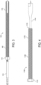
- FIGS. 3 , 6A , 7 , and 12B illustrate one example embodiment of the post-to-beam fastener of the present disclosure that is generally indicated by numeral 100.
- This illustrated example embodiment shows selected components of the post-to-beam fastener 100, and other components of the post-to-beam fastener 100 not discussed herein will be readily understood by those skilled in the art.
- the illustrated example post-to-beam fastener 100 includes: (1) a head 110; (2) a shank 140 integrally connected to the head 110 at a first end 142 of the shank 140; and (3) a tip 170 integrally connected to the shank 140 at a second end 144 of the shank 140.
- the post-to-beam fastener 100 i.e., the 1 Piece Concept
- the post-to-beam fastener 100 is configured as a 1/2 inch (1.27 cms) diameter bolt (i.e., fastener 100) with a tip 170 and a head 110 opposite of the tip 170.
- the post-to-beam fastener 100 is described as a 1/2 inch (1.27 cms) diameter bolt, any suitable different type of fastener and any suitable different size of fastener may be used in accordance with the present disclosure.
- the head 110 has a hexagonal shape and includes a retaining feature. More specifically, the head includes surfaces that define: (1) a recess 112 defined in a top surface (not labeled) of the head 110; and (2) a recess indent 114 defined in at least one sidewall (not labeled) of the recess 112.
- the surfaces of the head 110 that define the recess 112 are configured to engage with a fastener driving tool adapter 120 during driving and/or insertion of the fastener 100 into a workpiece (e.g., the beam or the post) (not shown).
- the surfaces that define the recess indent 114 are configured to positively retain the fastener driving tool adapter 120 in the recess 112 of the fastener 100 while a driving tool (not shown) drives the fastener 100 into a workpiece.
- the head 110 retains the fastener driving tool adapter 120 within the recess 112 while the fastener 100 is moved axially forward and backward within the workpiece during driving and/or insertion of the fastener 100 into the workpiece.
- the shank 140 includes a plurality of thread formations 146 extending outwardly from the shank 140 to form a threaded shank that connects to the head 110 at the first end 142 of the shank 140.
- the fastener 100 has the tip 170 at the second end 144 of the shank 140, and the shank 140 has a longitudinal axis extending from the head 110 to the tip 170.
- the tip 170 of the fastener 100 is configured as a drill tip, which may be milled or forged.
- the head 110 includes a feature to positively retain the fastener 100 to be moved forward and backward axially.
- the head 110, the shank 140, and the drill tip of tip 140 form a unitary structure that enables a user to drill and install the fastener 100 in one operation. That is, the fastener 100 including the tip 170 (i.e., the drill tip) drills, drives and/or inserts the fastener 100 into the workpiece without having to use a separate drill bit to first drill or otherwise form a hole through the workpiece.
- the tip 170 of the fastener 100 includes a flute 174 formed in the tip 170 of the fastener 100.
- the flute 174 is positioned proximate to the end of the tip 170; however other positions of the flute 174 are possible in accordance with the present disclosure.
- the flute 174 is configured to collect wood chips generated by drilling (i.e., the cutting action) of the drill tip on the workpiece (e.g., the deck post and the deck beam).
- wood chips can be removed periodically during drilling, driving and/or insertion of the fastener 100 through the workpiece (e.g., the deck post and the deck beam).
- the head 110 of the fastener 100 includes a square shaped recess 112 including the recess indent 114 (or hole) which enables the head to lock an adapter into the recess 112 of the head 110 (and positively retain the fastener).
- This method of drilling is known by a person skilled in the art as "peck-drilling.”
- FIGS. 6B and 12C illustrate another example embodiment of the post-to-beam fastener of the present disclosure that is generally indicated by numeral 200.
- This illustrated example embodiment of the post-to-beam fastener 200 is similar to fastener 100, as discussed above.
- This illustrated example embodiment shows selected components of the post-to-beam fastener 200, and other components of the post-to-beam fastener 200 not discussed herein will be readily understood by those skilled in the art.
- the illustrated example post-to-beam fastener 200 also referred to as a "1 Piece Fastener Concept," includes: (1) a head 210; (2) a shank 240 integrally connected to the head 210 at a first end 242 of the shank 240; and (3) a tip 270 suitably connected to the shank 240 at a second end 244 of the shank 140.
- the post-to-beam fastener 200 i.e., the 1 Piece Fastener Concept
- the post-to-beam fastener 200 is configured as a 1/2 inch (1.27 cms) diameter bolt (i.e., fastener 200) with the tip 270 and the head 210 opposite of the tip 170.
- the post-to-beam fastener 100 is described as a 1/2 inch (1.27 cms) diameter bolt, any suitable different type of fastener and any suitable different size of fastener may be used in accordance with the present disclosure.
- the head 210 is configured as a carriage bolt head and includes a retaining feature. More specifically, the head 210 includes surfaces that define: (1) a recess 212 defined in a top surface (not labeled) of the head 210; and (2) a recess indent 214 defined in at least one sidewall (not labeled) of the recess 212. In this illustrated example, the surfaces that define the recess 212 are configured to engage with the fastener driving tool adapter 120 (shown in FIGS. 3 and 12A ) during drilling, driving and/or insertion of the fastener 200 into a workpiece (e.g., the beam or the post) (not shown).
- a workpiece e.g., the beam or the post
- the surfaces that define the recess indent 214 are configured to positively retain the fastener driving tool adapter 120 in the recess 212 of the fastener 200 while a fastener driving tool (not shown) drives the fastener 200 into a workpiece.
- the head 210 retains the fastener driving tool adapter 120 within the recess 212 while the fastener 200 is moved axially forward and backward within the workpiece during drilling, driving and/or insertion of the fastener 200 into the workpiece.
- the shank 140 includes: (1) a square shoulder 245 adjacent to the first end 242 of the shank 240; and (2) a plurality of thread formations 246 extending outwardly from the shank 240 to form a threaded shank that connects to the head 210 at the square shoulder 245 of the shank 140.
- the fastener 200 has a tip 270 at second end 244 of the shank 240, and the shank 240 has a longitudinal axis extending from the head 210 to the tip 270.
- the tip 270 of the fastener 200 is configured as a drill tip, which may be milled or forged.
- the head 210 includes a feature to positively retain the fastener 200 to be moved forward and backward axially.
- the head 210, the shank 240, and the drill tip of tip 270 form a unitary structure that enables a user to drill and install the fastener 200 in one operation. That is, the fastener 200 including the tip 270 (i.e., the drill tip) drills, drives and/or inserts the fastener 200 into the workpiece without having to use a separate drill bit to first drill or otherwise form a hole through the workpiece.
- the tip 270 of the fastener 200 includes a flute 274 formed in the tip 270 of the fastener 200.
- the flute 274 is positioned proximate to the end of the tip 270, however other positions of the flute 274 are possible.
- the flute 274 is configured to collect wood chips generated by drilling (i.e., the cutting action) of the drill tip on the workpiece (e.g., the deck post and the deck beam). During operation, to improve the efficiency of the drill tip, wood chips can be removed periodically during drilling, driving and/or insertion of the fastener 200 through the workpiece.
- the head 210 of the fastener 200 includes surfaces that define a square shaped recess 212 including the recess indent 214 (or hole) and that lock an adapter into the recess 212 of the head 210 (i.e., positively retains the fastener). This permits the fastener 200 to be pulled out of the hole being generated in the workpiece, clearing out the woodchips collected from the flute 274 of the tip 270.
- the drill tip i.e., drill point
- the drill tip enables the user to drill, drive and/or install the fastener using a singular, complete assembly including a fastener and a drill tip.
- the flutes e.g., drill flutes or cutting flutes
- the flutes of the drill tip are formed or otherwise defined into the fastener itself.
- the flutes of the drill tip are approximately 2 inches (5.08 cms) long.
- Peck-drilling is typically used with flutes of such a length (e.g., 2 inches (5.08 cms) long).
- the flutes can vary in size, shape and number flutes that are defined on the tip of the fastener.
- longer drill flutes could be used, which may reduce the amount of backward and forward drilling (i.e., peck-drilling) used but may require the fastener to be longer overall.
- FIGS. 8A, 8B , 9 , 10A, 10B , and 11 illustrate several different drill tip and/or flute configurations.
- the drill tip may be broken, or knocked off of the end of the shank of the fastener by a hammer, or other such tool.
- the fastener includes a breakaway tip including the drill tip, and at least a portion of the flute.
- the breakaway tip is broken off at a breakaway line or breakaway joint.
- the breakaway tip is broken off from the fastener at the breakaway line or breakaway joint after a nut is installed on the fastener and tightened against the workpiece (e.g., the deck post and/or the deck beam).
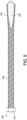
- FIGS. 8A and 8B illustrate selected components of another example embodiment of a post-to-beam fastener generally indicated by numeral 300.
- Post-to-beam fastener 300 is similar to fastener 100 discussed above and includes a milled drill tip and flute formed or otherwise defined in the tip of the post-to-beam fastener 300.
- the illustrated example post-to-beam fastener 300 includes: (1) a head 310; (2) a shank 340 integrally connected to the head 310 at a first end 342 of the shank 340; and (3) a tip 380 removably connected to the shank 340 at a second end 344 of the shank 340.
- the post-to-beam fastener 300 is configured as a 1/2 inch (1.27 cms) diameter bolt (i.e., fastener) with the head 310 opposite of the tip 380. It should be appreciated that while the post-to-beam fastener 300 is described as a 1/2 inch (1.27 cms) diameter bolt, any suitable different type of fastener and any suitable different size of fastener may be used in accordance with the present disclosure.
- the head 310 is configured with a hexagonal shape and includes a retaining feature. More specifically, the head 310 includes surfaces that define: (1) a recess (not shown) defined in a top surface (not labeled) of the head 310; and (2) a recess indent (not shown) defined in at least one sidewall (not labeled) of the recess. In this illustrated example, the surfaces that define the recess are configured to engage with a fastener driving tool adapter (not shown) during drilling, driving and/or insertion of the fastener 300 into a workpiece (e.g., the beam or the post) (not shown).
- a fastener driving tool adapter not shown
- the surfaces that define the recess indent are configured to positively retain the fastener driving tool adapter in the recess of the fastener 300 while a fastener driving tool (not shown) drills, drives, and/or inserts the fastener 300 into a workpiece.
- the head 310 retains the fastener driving tool adapter within the recess while the fastener 100 is moved axially forward and backward within the workpiece during drilling, driving and/or insertion of the fastener 300 into the workpiece.
- the shank 340 includes: (1) a plurality of thread formations 346 extending outwardly from the shank 340 to form a threaded shank that connects to the head 310 at the first end 342 of the shank 340; and (2) a breakaway line or breakaway joint 360 defined between the second end 344 of the shank 340 and the tip 380 of the fastener 300.
- the threaded shank i.e., shank 340
- the fastener 300 has a the tip 380 at second end 344 of the shank 340, and the shank 340 has a longitudinal axis extending from the head 310 to the tip 370.
- the drill tip of tip 380 includes a flute 384 formed in the tip 380 of the fastener 300. More specifically, the flute 384 is formed on the tip 380 and positioned between the breakaway line or breakaway joint 360 and the end of the tip 384, however other positions of the flute 384 are possible. As such, the flute 384 helps to collect wood chips generated by drilling (i.e., the cutting action) of the drill tip on the workpiece (e.g., the deck post and the deck beam).
- the tip 380 of the fastener 300 is configured as a breakaway drill tip, which is removed from the shank 340 of the fastener 300 once the drilling, driving, and/or insertion of the fastener 300 is complete.
- the breakaway drill tip of tip 380 enables a user to remove the drill tip from the fastener 300 once the hole is drilled through the workpiece and a nut (not shown) is installed around the thread formations 346 of the shank 340 and suitably tightened against the workpiece.
- the fastener 300 including the tip 380 drills drives and/or inserts the fastener 300 into the workpiece without having to use a separate drill bit to first drill or otherwise form a hole through the workpiece.
- FIGS. 9 , 10A, and 10B illustrate selected components of another example embodiment of a post-to-beam fastener generally indicated by numeral 400.
- Post-to-beam fastener 400 is similar to fastener 100 discussed above.
- Post-to-beam fastener 400 includes a forged drill tip (i.e., forged drill point). While the forged drill tip is similar to the milled drill tip and flute discussed above, the process to manufacture forged drilling tips is less expensive.
- an ending diameter of the forged drill tip of the fastener 400 is slightly larger than the 1/2 inch (1.27 cms) major diameter of threads of the fastener 400.
- the fastener 400 includes a breakaway tip that is removed or otherwise broken off before a nut is suitably installed on the fastener and suitably tightened against the workpiece because the ending diameter of the forged drill tip is larger than the threads of the fastener 400.
- the breakaway tip (see FIGS. 10A and 10B ) is used and knocked off by a hammer or other such tool before installation of the nut( not shown) onto the fastener 400.
- the illustrated example post-to-beam fastener 400 includes: (1) a head 410; (2) a shank 440 integrally connected to the head 410 at a first end 442 of the shank 440; and (3) a tip 490 suitably connected to the shank 440 at a second end 444 of the shank 440.
- the post-to-beam fastener 400 is configured as a 1/2 inch (1.27 cms) diameter bolt (i.e., fastener 400) with the head 410 opposite of the tip 490. It should be appreciated that while the post-to-beam fastener 400 is described as a 1/2 inch (1.27 cms) diameter bolt, any suitable different type of fastener and any suitable different size of fastener may be used in accordance with the present disclosure.
- the head 410 is configured with a hexagonal shape and includes a retaining feature. More specifically, the head 410 includes surfaces that define: (1) a recess (not shown) defined in a top surface (not labeled) of the head 410; and (2) a recess indent (not shown) defined in at least one sidewall (not labeled) of the recess. In this illustrated example, the surfaces that define the recess are configured to engage with a fastener driving tool adapter (not shown) during drilling, driving and/or insertion of the fastener 400 into a workpiece (e.g., beam or post) (not shown).
- a fastener driving tool adapter not shown
- the surfaces that define the recess indent are configured to positively retain the fastener driving tool adapter in the recess of the fastener 400 while a fastener driving tool (not shown) drills, drives and/or inserts the fastener 400 into a workpiece.
- the head 410 retains the fastener driving tool adapter within the recess while the fastener 400 is moved axially forward and backward within the workpiece during drilling, driving and/or insertion of the fastener 400 into the workpiece.
- the shank 440 includes: (1) a plurality of thread formations 446 extending outwardly from the shank 440 to form a threaded shank that connects to the head 410 at the first end 442 of the shank 340; and (2) a breakaway line or breakaway joint 460 disposed between the second end 444 of the shank 440 and the tip 490 of the fastener 400.
- the threaded shank i.e., shank 440
- the fastener 400 forms the tip 490 at second end 444 of the shank 440
- the shank 440 has a longitudinal axis extending from the head 410 to the tip 490.
- the tip 490 includes: (1) a first outer diameter 492 at a first end of the tip 490 adjacent to the breakaway line or breakaway joint 460; and (2) a second outer diameter 494 at a second end of the tip 490 opposite the first end.
- the second outer diameter 494 of the tip 490 is slightly larger than the major diameter of the thread formations 446 of the shank 440.
- the tip 490 of the fastener 400 produces a hole in the workpiece that is slightly larger than the major diameter of the thread formations 446 of the shank 440.
- the tip 490 of the fastener 400 is configured as a breakaway drill tip, which is removed from the shank 440 of the fastener 400 once a hole is drilled through the workpiece.
- the fastener 400 including the tip 490 drills a hole into the workpiece without having to use a separate drill bit to drill or otherwise form a hole through the workpiece.
- the tip 490 is removed from the fastener 400 at the breakaway line or breakaway joint 460 such that a nut (not shown) is suitably installed around the thread formations 446 of the shank 440 and suitably tightened against the workpiece.
- FIG. 11 illustrates selected components of an additional example embodiment of a post-to-beam fastener generally indicated by numeral 600.
- the post-to-beam fastener 600 is similar to fastener 100 discussed above and includes a winged drill tip (i.e., winged cutting tip) formed or otherwise defined in the tip of the post-to-beam fastener 600.
- the winged drill tip of the fastener 600 is used to cut, drill, or otherwise form a proper hole diameter in a workpiece for the installation of the fastener 600.
- the winged cutting tip of the fastener 600 is a breakaway tip.
- only the wings of the winged cutting tip breakaway from the fastener. For example, the wings break off of the winged cutting tip when a specialized nut is installed on the fastener and suitably tightened against the deck post and deck beam.
- the illustrated example post-to-beam fastener 600 includes: (1) a head 610; (2) a shank 640 integrally connected to the head 610 at a first end 642 of the shank 640; and (3) a tip 670 suitably connected to the shank 640 at a second end 644 of the shank 640.
- the post-to-beam fastener 600 is configured as 1 ⁇ 2 inch (1.27 cms) diameter bolt (i.e., fastener 600) with the head 610 opposite of the tip 670. It should be appreciated that while the post-to-beam fastener 600 is described as a 1/2 inch (1.27 cms) diameter bolt, any suitable different type of fastener and any suitable different size of fastener may be used in accordance with the present disclosure.
- the head 610 is configured with a hexagonal shape and includes a retaining feature. More specifically, the head 610 includes surfaces that define: (1) a recess (not shown) defined in a top surface (not labeled) of the head 610; and (2) a recess indent (not shown) defined in at least one sidewall (not labeled) of the recess. In this illustrated example, the surfaces that define the recess are configured to engage with a fastener driving tool adapter (not shown) during drilling, driving and/or insertion of the fastener 600 into a workpiece (e.g., beam or post) (not shown).
- a fastener driving tool adapter not shown
- the surfaces that define the recess indent are configured to positively retain the fastener driving tool adapter in the recess of the fastener 600 while a fastener driving tool (not shown) drills, drives and/or inserts the fastener 600 into a workpiece.
- the head 610 retains the fastener driving tool adapter within the recess while the fastener 600 is moved axially forward and backward within the workpiece during drilling, driving and/or insertion of the fastener 600.
- the shank 640 includes: (1) a plurality of thread formations 646 extending outwardly from the shank 640 to form a threaded shank that connects to the head 610 at the first end 642 of the shank 640; and (2) a breakaway line breakaway joint 660 disposed between the second end 644 of the shank 640 and the tip 670 of the fastener 400.
- the threaded shank i.e., shank 640
- the fastener 600 has the tip 670 at second end 644 of the shank 640, and the shank 640 has a longitudinal axis extending from the head 610 to the tip 670.
- the drill tip of the tip 670 includes: (1) a first wing formation 674a extending radially from an outer surface of the tip 670; and (2) a second wing formation 674b extending radially from the outer surface of the tip 670.
- the first and second wing formations 674a and 674b define a wing formation diameter that is slightly larger than an outer diameter of the tip 670.
- the wing formation diameter of the first and second wing formations 674a and 674b is slightly larger than the major diameter of the thread formations 646 of the shank 640.
- the tip 670 and the first and second wing formations 674a and 674b of the fastener 600 produce a hole in the workpiece that is slightly larger than the than the major diameter of the thread formations 646 of the shank 640.
- the tip 670 of the fastener 600 is configured as a breakaway drill tip, which is removed from the shank 640 of the fastener 600 once a hole is drilled through the workpiece.
- the fastener 600 including the tip 670 drills a hole into the workpiece without having to use a separate drill bit to drill or otherwise form a hole through the workpiece.
- the tip 670 including the first and second wing formations 674a and 674b is removed from the fastener 600 at the breakaway line or breakaway joint 660 such that a nut (not shown) is suitably installed around the thread formations 646 of the shank 640 and suitably tightened against the workpiece.
- the wings break away from the tip of the fastener. More specifically, the first and second wing formations are configured to break away or otherwise be removed from the tip of the fastener following the drilling of the hole in the workpiece. For example, the wings break off when a specialized nut is installed on the bolt and tightened against the deck post and deck beam. As such, the nut is configured to break off or otherwise remove the first and second wing formations as the nut is suitably installed on the fastener and suitably tightened against the workpiece. As such, in this example embodiment, the tip remains suitably connected to the fastener following the drilling, driving, and/or insertion of the fastener into the workpiece.
- FIGS. 4 , 13A, and 13B illustrate another example embodiment of the post-to-beam fastener of the present disclosure that is generally indicated by numeral 1100.
- This illustrated example embodiment shows selected components of the post-to-beam fastener 1100, and other components of the post-to-beam fastener 1100 not discussed herein will be readily understood by those skilled in the art.
- the illustrated example post-to-beam fastener 1100 includes: (1) a head 1110; (2) a shank 1140 integrally connected to the head 1110 at a first end 1142 of the shank 1140; (3) a tip 1170 integrally connected to the shank 1140 at a second end 1144 of the shank 140; and (4) a drill bit 1180 removably attached to the tip 1170 of the fastener 1100.
- the post-to-beam fastener 1100 is referred to as a "2 Piece Fastener Concept.” that includes a 1/2 inch ( 1.27 cms) diameter bolt (i.e., fastener 1100) with a recess in an end (i.e., the tip 1170) of the bolt to removably attach the drill bit 1180.
- the drill bit 1180 is attached to the tip 1170 of the post-to-beam fastener 1100 and the user drills a hole through a workpiece (e.g., the deck post and the deck beam). After drilling is complete, the drill bit 1170 is removed from the fastener 1100.
- utilizing a drill bit produces efficient drilling and/or cutting action of the 2 Piece Fastener Concept.
- the post-to-beam fastener 1100 is described as a 1 ⁇ 2 inch (1.27 cms) diameter bolt, any suitable different type of fastener and any suitable different size of fastener may be used in accordance with the present disclosure.
- a drill bit with a hex shank can be received in a hex recess of the end of the fastener (e.g., a 1/4 inch (.635 cms) hex recess accommodating a 1/4 inch (.635 cms) hex shank spade bit).
- customized drill bits are created to optimize attachment to the recess in the end of the fastener.
- the 2 Piece Fastener Concept provides a faster user experience.
- the 2 Piece Fastener Concept operation begins with connecting the bolt (i.e., fastener) to the drill driver. This can be done using a socket, star, or square drive adapter.
- a drill bit is inserted into the recess on the tip end of the fastener.
- the recess at the end of the fastener enables the user to install various common drill bits.
- the drill bit is used to drill the fastener through the workpiece (e.g., the deck post and/or the deck beam). Once the cutting operation has been completed, the drill bit can be removed from the other side of the post (and used with subsequent 2 Piece Fastener Concept fasteners, or any other operation).
- a washer and nut are installed and tightened.
- the head 1110 is configured with a hexagonal shape and includes a retaining feature. More specifically, the head 1110 includes surfaces that define: (1) a recess (not shown) defined in a top surface (not labeled) of the head 1110; and (2) a recess indent (not shown) defined in at least one sidewall (not shown) of the recess.
- the surface that define the recess are configured to engage with a fastener driving tool adapter (not shown) during drilling, driving and/or insertion of the fastener 1100 into a workpiece (e.g., the beam or the post) (not shown).
- the surfaces that define the recess indent are configured to positively retain the fastener driving tool adapter in the recess of the fastener 1100 while a driving tool (not shown) drives the fastener 1100 into a workpiece.
- the head 1110 retains the fastener driving tool adapter within the recess while the fastener 1100 is moved axially forward and backward within the workpiece during driving and/or insertion of the fastener 100 into the workpiece.
- the shank 1140 includes a plurality of thread formations 1146 extending outwardly from the shank 1140 to form a threaded shank that connects to the head 1110 at the first end 1142 of the shank 1140.
- the threaded shank i.e., shank 1140
- the fastener 1100 forms the tip 1170 at second end 1144 of the shank 1140
- the shank 1140 has a longitudinal axis extending from the head 610 to the tip 670.
- the tip 1170 of the fastener 1100 includes surfaces that define a recess 1176 in the tip 1170 to removably attach the drill bit 1180 to the fastener 1100.
- the recess 1176 is configured as a hex recess (e.g., a 1/4 inch (.635 cms) hex recess) that accepts any standard hex shank drill bits (e.g., 1/4 inch (.635 cms) hex shank drill bits)
- the recess 1176 does not provide any positive engagement of the drill bit 1180.
- the drill bit 1180 is easily removed from the recess 1176 of the fastener 1100 after drilling and/or cutting a hole through a workpiece.
- the recess of the fastener includes an additional positive retaining feature (not shown) (e.g., similar to the indent described in FIG. 12B with respect to the head 110 of the 1 Piece Fastener Concept fastener 100) to removably secure the drill bit in the end of the fastener.
- the positive retaining feature secures the drill bit in place within the recess, along with the force from the operator while drilling.
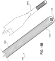
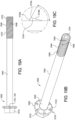
- FIGS. 16A and 16B illustrate another example embodiment of the post-to-beam fastener of the present disclosure that is generally indicated by numeral 1200.
- the post-to-beam fastener 1200 is similar to fastener 1100, discussed above.
- This illustrated example embodiment shows selected components of the post-to-beam fastener 1100, and other components of the post-to-beam fastener 1100 not discussed herein will be readily understood by those skilled in the art.
- the illustrated example post-to-beam fastener 1200 includes: (1) a head 1210; (2) a shank 1240 integrally connected to the head 1210 at a first end 1242 of the shank 1240; (3) a tip 1270 integrally connected to the shank 1240 at a second end 1244 of the shank 1240; and (4) a drill bit 1280a removably attached to the tip 1270 of the fastener 1200.
- the post-to-beam fastener 1200 is referred to as a "2 Piece Fastener Concept.” that includes a 1/2 inch (1.27 cms) diameter bolt (i.e., fastener 1200) with a recess in an end (i.e., the tip 1270) of the fastener to removably attach the drill bit to the fastener.
- the drill bit 1280 is attached to the tip 1270 of the post-to-beam fastener 1200 and the user drills a hole through a workpiece (e.g., the deck post and the deck beam). After drilling is complete, the drill bit 1280a is removed from the fastener 1200.
- utilizing a drill bit produces efficient drilling and/or cutting action of the 2 Piece Fastener Concept fastener.
- the post-to-beam fastener 1200 is described as a 1/2 inch (1.27 cms) diameter bolt, any suitable different type of fastener and any suitable different size of fastener may be used in accordance with the present disclosure.
- the head 1210 is configured with a hexagonal shape and includes a retaining feature. More specifically, the head 1210 includes surfaces that define: (1) a recess (not shown) defined in a top surface (not labeled) of the head 1210; and (2) a recess indent (not shown) defined in at least one sidewall (not shown) of the recess. In this illustrated example, the surfaces that define the recess are configured to engage with a fastener driving tool adapter (not shown) during drilling, driving and/or insertion of the fastener 1200 into a workpiece (e.g., the beam or the post) (not shown).
- a fastener driving tool adapter not shown
- the surfaces that define the recess indent are configured to positively retain the fastener driving tool adapter in the recess of the fastener 1200 while a driving tool (not shown) drives the fastener 1200 into a workpiece.
- the head 1210 retains the fastener driving tool adapter within the recess while the fastener 1200 is moved axially forward and backward within the workpiece during drilling, driving and/or insertion of the fastener 1200 into the workpiece.
- the shank 1240 includes a plurality of thread formations 1246 extending outwardly from the shank 1240 to form a threaded shank that connects to the head 1210 at the first end 1242 of the shank 1240.
- the threaded shank i.e., shank 1240
- the fastener 1200 forms the tip 1270 at second end 1244 of the shank 1240
- the shank 1240 has a longitudinal axis extending from the head 1210 to the tip 1270.
- the tip 1270 of the fastener 1200 includes surfaces that define a threaded recess 1276 in the tip 1270 to removably attach to one of a plurality of different drill bits such as drill bits 1280a, 1280b, or 1280c.
- the threaded recess 1276 includes an internal thread formation (not labeled) (e.g., a 1/4-20 internal thread) extending from a surface of the threaded recess 1276 of the tip 1270 of the fastener 1200.
- the internal thread formation is configured to mate or otherwise accept a drill bit having a complimentary external thread formation (e.g., external 1/4-20 threads).
- the threaded recess 1276 including the internal thread formation has an advantage in that the threads of the threaded recess 1276 positively engage the threads of the drill bit so it stays locked into place while drilling. Once the operation is finished, the drill bit is unscrewed and reused.
- users such as contractors or deck builders
- carriage bolts that have a low-profile head compared to hex bolts or other such bolts.
- the low-profile head of carriage bolts may be perceived to look cleaner and more professional than hex bolts by homeowners (customers of the deck builders).
- Carriage bolts have no sharp edges that may interfere with homeowners using the deck.
- Known carriage bolts have a square shoulder that locks the bolt into the wood when driven with a hammer.
- the bolt To attach a nut to the bolt at the end of the post-to-beam fastening process, the bolt must be rotatably held in place by the wood.
- the square shoulder reams a hole in the wood, allowing the bolt to rotate freely. Then, the bolt cannot be rotatably held in place by the wood, thus removing the ability to fasten the connection with a nut.
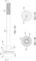
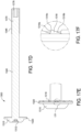
- FIGS. 17A to 17F illustrate another example embodiment of the post-to-beam fastener of the present disclosure that is generally indicated by numeral 1300.
- the post-to-beam fastener 1300 is a bolt (i.e., fastener 1300) for use in the 2 Piece Fastener Concept for post-to-beam fastening.
- the fastener 1300 is a carriage bolt with a locking rib pattern replacing the square shoulder.
- the locking rib pattern consisting of a plurality of ribs extending radially from the shank to the edge of the head, resists rotation and rotatably holds the fastener 1300 in place by engagement with the workpiece (e.g., the deck post and/or the deck beam).
- Each of the plurality of ribs is angled such that the fastener 1300 can spin freely in a clockwise direction but dig in when the fastener 1300 tries to rotate counterclockwise. Tightening a nut onto the fastener 1300 after drilling through the workpiece induces a counterclockwise rotation in the fastener, so if the ribs prevent this rotation, the fastener can be tightened fully.
- the illustrated example post-to-beam fastener 1300 includes: (1) a head 1310; (2) a shank 1340 integrally connected to the head 1310 at a first end 1342 of the shank 1340; (3) a tip 1370 integrally connected to the shank 1340 at a second end 1344 of the shank 1340; and (4) a drill bit (not shown) removably attached to the tip 1370 of the fastener 1300.
- the head 1310 is configured as a carriage bolt head and includes a retaining feature. More specifically, the head 1310 includes surfaces that define: (1) a recess 1312 defined in a top surface (not labeled) of the head 1310; and (2) a locking rib pattern 1316 including a plurality of ribs 1318 extending outwardly from a bottom surface (not labeled) of the head 1310.
- the surfaces that define the recess 1312 are configured to engage with a fastener driving tool adapter (not shown) during drilling, driving and/or insertion of the fastener 1300 into a workpiece (e.g., the beam or the post) (not shown).
- the plurality of ribs 1318 of the rib locking pattern 1316 engages with the workpiece such that the fastener 1300 does not freely spin when a nut (not shown) is suitably tightened around the fastener 1300.
- recess 1312 is shown as a star-shaped recess, other recesses may be used, such as a socket recess (engageable by a socket), and a square recess (engageable by a square drive adapter).
- each rib 1318 of the locking rib pattern 1316 includes a leading face 1318a and a trailing face 1318b that meet at an apex 1318c of the rib 1318.
- the leading face 1318a forms an angle (not labeled) with respect to the bottom surface of the head 1310.
- the trailing face 1318b forms an angle (not labeled) with respect to the bottom surface of the head 1310.
- the angle formed between the leading face 1318a and the bottom surface of the head 1310 is greater than the angle formed between the trailing face 1318b and the bottom surface of the head 1310.
- the shank 1340 includes a plurality of thread formations 1346 extending outwardly from the shank 1340 to form a threaded shank that connects to the head 1310 at the first end 1342 of the shank 1340.
- the thread formations 1346 of the shank 1340 are configured such that tightening a nut onto the fastener 1300 induces a counter-clockwise rotation of the fastener 1300, and loosening the nut from the fastener 1300 induces a clockwise rotation of the fastener 1300.
- the fastener 1300 is tightened against the workpiece, causing the locking rib pattern 1316 to come into contact with the workpiece.
- the fastener 1300 is loosened or backed away from the workpiece, causing the locking rib pattern 1316 to come out of contact with the workpiece.
- the tightening of the nut induces a counter-clockwise rotation of the fastener 1300, and the apex 1318c and leading edges 1318a of the ribs 1318 come into contact with the workpiece,
- the sharper angle of the leading edges 1318a contact the workpiece during the tightening process, creating a rotational resistance with respect to the workpiece by "biting" into the surface of the workpiece.
- the interaction between the ribs 1318 and the workpiece prevent the fastener from spinning while the nut is being tightened.
- the tip 1370 of the fastener 1300 includes surfaces that define a recess 1376 in the tip 1370 to removably attach the drill bit (not shown) to the fastener 1300.
- the recess 1376 is configured as a hex recess (e.g., a 1/4 inch (.635 cms) hex recess) that accepts any standard hex shank drill bits (e.g., 1/4 inch (.635 cms) hex shank drill bits).
- the recess 1376 does not provide any positive engagement of the drill bit.
- the drill bit is easily removed from the recess 1376 of the fastener 1300 after drilling and/or cutting a hole through a workpiece.
- a washer 1320 is integrated with the head 1310 of the fastener 1300.
- An integrated washer further reduces the number of pieces that users have to handle during installation (though some users may not presently use washers with known carriage bolts).
- the integrated washer also increases the bearing surface area of the head of the fastener. A larger bearing surface may provider a tighter post-to-beam connection, resulting in peace of mind for users and their customers.
- the head 1310 of the fastener 1300 has a diameter similar to a standard fender washer. Other diameters between a known carriage bolt and standard fender washer, or greater than the standard fender washer, are also possible.
- FIGS. 18A, 18B , 18C, and 18D illustrate another example embodiment of the post-to-beam fastener of the present disclosure that is generally indicated by numeral 1400.
- the post-to-beam fastener 1400 is similar to fastener 1100, discussed above.
- This illustrated example embodiment shows selected components of the post-to-beam fastener 1400, and other components of the post-to-beam fastener 1400 not discussed herein will be readily understood by those skilled in the art.
- the illustrated example post-to-beam fastener 1400 includes: (1) a head 1410; (2) a shank 1440 integrally connected to the head 1410 at a first end 1442 of the shank 1440; (3) a tip 1470 integrally connected to the shank 1440 at a second end 1444 of the shank 1440; and (4) a drill bit 1480 removably attached to the tip 1470 of the fastener 1400.
- the post-to-beam fastener 1400 is referred to as a "2 Piece Fastener Concept.” that includes a 1/2 inch ( 1.27 cms) diameter bolt (i.e., fastener 1200) with a recess in an end (i.e., the tip 1470) of the fastener to removably attach the drill bit to the fastener.
- the drill bit 1480 is attached to the tip 1470 of the post-to-beam fastener 1400 and the user drills a hole through a workpiece (e.g., the deck post and the deck beam). After drilling is complete, the drill bit 1480 is removed from the fastener 1400.
- utilizing a drill bit produces efficient drilling and/or cutting action of the 2 Piece Fastener Concept fastener.
- the post-to-beam fastener 1400 is described as a 1/2 inch (1.27 cms) diameter bolt, any suitable different type of fastener and any suitable different size of fastener may be used in accordance with the present disclosure.
- the head 1410 is configured with a hexagonal shape and includes a retaining feature. More specifically, the head 1410 includes surfaces that define: (1) a recess (not shown) defined in a top surface (not labeled) of the head 1410; (2) a recess indent (not shown) defined in at least one sidewall (not shown) of the recess; and (3) a washer 1420 is integrated with the head 1410 of the fastener 1400.
- the surfaces that define the recess are configured to engage with a fastener driving tool adapter (not shown) during drilling, driving and/or insertion of the fastener 1400 into a workpiece (e.g., the beam or the post) (not shown).
- the surfaces that define the recess indent are configured to positively retain the fastener driving tool adapter in the recess of the fastener 1400 while a driving tool (not shown) drives the fastener 1400 into a workpiece.
- the head 1410 retains the fastener driving tool adapter within the recess while the fastener 1400 is moved axially forward and backward within the workpiece during drilling, driving and/or insertion of the fastener 1400 into the workpiece.
- the shank 1440 includes: (1) a plurality of thread formations 1446 extending outwardly from at least a portion of the shank 1440 to form a threaded shank that connects to the head 1410 at the first end 1442 of the shank 1440; and (2) one or more v-grooves 1448 defined in and by the thread formations 1446.
- the threaded shank i.e., shank 1440
- the fastener 1400 forms the tip 1470 at second end 1444 of the shank 1440
- the shank 1440 has a longitudinal axis extending from the head 1410 to the tip 1470.
- the one or more v-grooves 1448 defined in the thread formations 1446 extend along a portion of the thread formations 1446 (e.g., 3/4 of an inch (1.905 cms) of the thread formations 1446).
- the one or more v-grooves 1448 cause a reduction of the friction generated by the cutting action of the thread formations 1446 into the workpiece during drilling, driving, and/or insertion of the fastener 1400 into the workpiece.
- the tip 1470 of the fastener 1400 includes surfaces that define a recess 1476 in the tip 1470 to removably attach to the drill bit 1480.
- the recess 1476 is configured as a hex recess (e.g., a 1/4 inch (.635 cms) hex recess) that accepts any standard hex shank drill bits (e.g., 1/4 inch (.635 cms) hex shank drill bits).
- the recess 1476 does not provide any positive engagement of the drill bit 1480.
- the drill bit 1480 is easily removed from the recess 1476 of the fastener 1400 after drilling and/or cutting a hole through a workpiece.
- FIGS. 19A, 19B, 19C , 19D, and 19E illustrate various alternative further example embodiments of the post-to-beam fastener of the present disclosure that are generally indicated by numeral 1500.
- the post-to-beam fastener 1500 shown in FIGS. 19A, 19B, 19C , and 19D is similar to fastener 1100, discussed above.
- This illustrated example embodiment shows selected components of the post-to-beam fastener 1500, and other components of the post-to-beam fastener 1500 not discussed herein will be readily understood by those skilled in the art.
- the illustrated example post-to-beam fastener 1500 includes: (1) a head 1510; (2) a shank 1540 integrally connected to the head 1510 at a first end 1542 of the shank 1540; (3) a tip 1570 integrally connected to the shank 1540 at a second end 1544 of the shank 1540; and (4) a drill bit (not shown) removably attached to the tip 1570 of the fastener 1500.
- the head 1510 is configured with a hexagonal shape and includes: (1) a washer 1520 integrated with the head 1510 of the fastener 1500; and (2) a locking rib pattern 1516 including a plurality of ribs 1518 extending outwardly from a bottom surface (not labeled) of the washer 1520 integrated with the head 1510.
- the washer 1520 is configured as a standard washer having a diameter of substantially 1.06 inches (2.6924 cms). In another example, the washer (not shown) is configured as a larger fender-type washer having a diameter of substantially 1.375 inches (3.4925 cms). It should be appreciated that while two washers having different dimensions are discussed, other suitable integrated washers having other suitable dimensions may be used in accordance with the present disclosure.
- each rib 1518 of the locking rib pattern 1516 includes a leading face 1518a and a trailing face 1518b that meet at an apex 1518c of the rib 1518.
- the leading face 1518a forms an angle (not labeled) with respect to the bottom surface of the washer 1520 integrated with the head 1510.
- the trailing face 1518b forms an angle (not labeled) with respect to the bottom surface of the washer 1520 integrated with the head 1510.
- the angle formed between the leading face 1518a and the bottom surface of the washer 1520 is greater than the angle formed between the trailing face 1518b and the bottom surface of the washer 1520.
- the leading face 1518a is at a sharper angle with respect to the workpiece (not shown), and the trailing face 1518b is at a shallower angle with respect to the workpiece.
- the plurality of ribs 1518 of rib pattern 1516 include partial ribs configured to radially extend from a location along the outer circumference of the washer 1520 to an interior location spaced a specified distance from the shank 1540. As such, the ribs 1516 radially extend along the surface of the washer 1520 a partial distance between the outer circumference of the washer and the shank 1540.
- the shank 1540 includes: (1) a plurality of thread formations 1546 extending outwardly from at least a portion of the shank 1540 to form a threaded shank that connects to the head 1510 at the first end 1542 of the shank 1540; and (2) one or more v-grooves 1548 defined in the thread formations 1546.
- the threaded shank i.e., shank 1540
- the fastener 1500 forms the tip 1570 at second end 1544 of the shank 1540
- the shank 1540 has a longitudinal axis extending from the head 1510 to the tip 1570.
- the one or more v-grooves 1548 defined in the thread formations 1546 extend along a portion of the thread formations 1546 (e.g., 3/4 of an inch (1.905 cm) of the thread formations 1546).
- the one or more v-grooves 1548 cause a reduction of the friction generated by the cutting action of the thread formations 1546 into the workpiece during drilling, driving, and/or insertion of the fastener 1500 into the workpiece.
- the tip 1570 of the fastener 1500 includes surfaces that define a recess 1576 in the tip 1570 to removably attach to a drill bit (not shown).
- the recess 1576 is configured as a hex recess (e.g., a 1/4 inch (.635 cms) hex recess) that accepts any standard hex shank drill bits (e.g., 1/4 inch (.635 cms) hex shank drill bits).
- the recess 1576 does not provide any positive engagement of the drill bit. That is, there is nothing securing the drill bit in place within the recess 1576, besides the force from the operator while drilling. As such, in this illustrated example, the drill bit is easily removed from the recess 1576 of the fastener 1500 after drilling and/or cutting a hole through a workpiece.
- the fastener 1600 includes a plurality of ribs 1618 of rib pattern 1616 that include full ribs configured to radially extend from a location along the outer circumference of the washer 1620 to an interior location adjacent to the shank 1640.
- the ribs 1618 radially extend along the surface of the washer 1620 the entire distance between the outer circumference of the washer 1620 and the shank 1640.
- the feature e.g., the recess in the head
- the feature to positively retain the bolt to be moved forward and backward axially
- small wood chips are created within the hole.
- these chips should be cleared to allow for more chips to be created. If these chips are not cleared the drill tip will get clogged with chips, thus impeding advancement of the drill tip and heating the drill tip due to excessive friction.
- a positive engagement head clears the wood chips by allowing the bolt to be pulled back and forth out of the hole.
- FIGS. 12A and 12B illustrate a 1/4 inch (.635 cms) Hex to 1/4 inch (.635 cms) Square Adapter.
- This adapter includes a ball detent which locks into the indent (or hole) defined surfaces of the square recess defined in surfaces of the head of the bolt.
- the positive engagement provided by the 1/4 inch (.635 cm) Hex to 1/4 inch (.635 cms) Square Adapter enables the bolt to be pulled back and forth out of the hole to clear the wood chips generated while drilling the hole.
- FIGS. 13 , 14A, and 14B illustrate an integrated driving tool adapter integrated with the head of the bolt allowing for direct attachment of the integrated driving tool adapter to the drill chuck.
- This direct attachment is a form of positive engagement, as the drill chuck locks into the integrated driving tool adapter.
- the positive engagement provided by the integrated driving tool adapter enables the bolt to be pulled back and forth out of the hole to clear the wood chips generated while drilling the hole.
- the recess at the end of the bolt enables the user to install various common drill bits for use in the post-to-beam fastener installation methods of the present disclosure.
- the drill bit is inserted into the end of the bolt and used to drill the bolt through the post. Once the cutting operation has been completed, the drill bit can be removed (and used with subsequent 2 Piece Concept bolts, or any other operation).
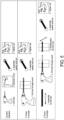
- FIG. 5 illustrates a comparison between methods of post-to-beam fastening using known methods (the "Current Solution"), the 1 Piece Fastener Concept of the present disclosure, and the 2 Piece Fastener Concept of the present disclosure.
- the known method begins with a drill bit attached to the drill driver. A 1/2 inch hole is pre-drilled through the post, and a 1/2 inch (1.27 cms) through bolt is hammered into the hole. A washer and nut are attached and tightened.
- the 1 Piece Fastener Concept and the 2 Piece Fastener Concept provide a faster user experience.
- the 1 Piece Fastener Concept operation begins with positively retaining the bolt (i.e., at the square recess with hole in the head) to the drill driver.
- the bolt is drilled and driven through the wood using the peck-drilling technique described above.
- the drill driver is removed from the head of the bolt.
- a washer and nut are assembled on the end of the bolt, and the entire assembly is fastened tightly together.
- the 2 Piece Fastener Concept operation begins with connecting the bolt to the drill driver. This can be done using a socket, star, or square drive adapter. Next, a 6 inch (15.24 cms) long drill bit is inserted into the recess on the tip end of the bolt. The bolt is drilled and driven into the post in one motion without the peck-drilling used by the 1 Piece Concept operation. The drill bit is then removed from the other side of the post, and a washer and nut are installed and tightened.
- the 1 Piece Fastener Concept and 2 Piece Fastener Concept of the present disclosure combine pre-drilling and bolt installation steps of post-to-beam fastening into one step. Use of the bolts and methods of the present disclosure result in faster and more efficient installations of deck posts and deck beams.
Landscapes
- Engineering & Computer Science (AREA)
- General Engineering & Computer Science (AREA)
- Mechanical Engineering (AREA)
- Architecture (AREA)
- Physics & Mathematics (AREA)
- Electromagnetism (AREA)
- Civil Engineering (AREA)
- Structural Engineering (AREA)
- Drilling Tools (AREA)
- Connection Of Plates (AREA)
Applications Claiming Priority (4)
| Application Number | Priority Date | Filing Date | Title |
|---|---|---|---|
| US201862737046P | 2018-09-26 | 2018-09-26 | |
| US201962834856P | 2019-04-16 | 2019-04-16 | |
| US16/580,465 US11692578B2 (en) | 2018-09-26 | 2019-09-24 | Post-to-beam fastener |
| PCT/US2019/052939 WO2020068970A1 (en) | 2018-09-26 | 2019-09-25 | Post-to-beam fastener |
Publications (2)
| Publication Number | Publication Date |
|---|---|
| EP3857076A1 EP3857076A1 (en) | 2021-08-04 |
| EP3857076B1 true EP3857076B1 (en) | 2024-11-06 |
Family
ID=69884046
Family Applications (1)
| Application Number | Title | Priority Date | Filing Date |
|---|---|---|---|
| EP19783892.3A Active EP3857076B1 (en) | 2018-09-26 | 2019-09-25 | Post-to-beam fastener |
Country Status (7)
| Country | Link |
|---|---|
| US (3) | US11692578B2 (da) |
| EP (1) | EP3857076B1 (da) |
| AU (2) | AU2019346445B2 (da) |
| CA (1) | CA3109985C (da) |
| DK (1) | DK3857076T3 (da) |
| FI (1) | FI3857076T3 (da) |
| WO (1) | WO2020068970A1 (da) |
Families Citing this family (2)
| Publication number | Priority date | Publication date | Assignee | Title |
|---|---|---|---|---|
| FR3049892B1 (fr) * | 2016-04-07 | 2018-04-06 | Maxime Grojean | Composant de fixation et procede de fabrication d’une piece composite avec ce composant |
| US12305678B2 (en) * | 2022-04-05 | 2025-05-20 | Illinois Tool Works Inc. | Expandable anchor installation tool and methods of use thereof |
Citations (5)
| Publication number | Priority date | Publication date | Assignee | Title |
|---|---|---|---|---|
| GB1482624A (en) * | 1974-08-20 | 1977-08-10 | Barnsdale A | Self-tapping screw threaded members |
| DE202005017976U1 (de) * | 2005-11-15 | 2007-03-29 | Dr. Hahn Gmbh & Co. Kg | Montageschraube zur Befestigung von Beschlagteilen, insbesondere von Bandteilen an Hohlkammerprofilen |
| CA2616478A1 (en) * | 2007-12-28 | 2009-06-28 | Yu-Sheng Tseng | Fastener with removable element |
| US20090175701A1 (en) * | 2008-01-03 | 2009-07-09 | Cheng-Yuan Wu | Self-tapping screw made of composite material |
| EP3225858A1 (en) * | 2016-03-30 | 2017-10-04 | Kuo-Tai Hsu | Screw |
Family Cites Families (153)
| Publication number | Priority date | Publication date | Assignee | Title |
|---|---|---|---|---|
| CA236690A (en) | 1924-01-01 | Abbass Joub | Motor | |
| US781652A (en) | 1904-04-06 | 1905-02-07 | Charles Christopher Hiatt | Auger-bit. |
| US808245A (en) | 1905-02-07 | 1905-12-26 | Joel Lund | Wood-boring implement. |
| US996612A (en) | 1908-06-24 | 1911-07-04 | John William Caldwell | Auger-bit. |
| US1764053A (en) | 1928-06-15 | 1930-06-17 | Reed And Prince Mfg Company | Rolled-thread wood screw |
| US2035298A (en) | 1932-07-14 | 1936-03-24 | John W Caldwell | Auger bit |
| US2034494A (en) | 1934-12-04 | 1936-03-17 | Clare L Brackett | Washer |
| US2914983A (en) | 1953-12-09 | 1959-12-01 | Olin Mathieson | Explosively driven fastener having axially collapsible radially expandable locking sleeve |
| GB888309A (en) | 1956-04-19 | 1962-01-31 | Illinois Tool Works | Improvements in screw fasteners |
| US2993950A (en) * | 1959-06-17 | 1961-07-25 | Formar Ind Inc | Self-tapping non-conductive fastener |
| BE661105A (da) | 1964-03-19 | 1965-07-01 | ||
| US3316796A (en) | 1965-06-24 | 1967-05-02 | Jacob H Young | Self-drilling expansion anchor bolt |
| US3389734A (en) | 1967-03-28 | 1968-06-25 | Illinois Tool Works | Locking and sealing screw |
| FR1590097A (da) | 1968-03-05 | 1970-04-13 | ||
| US3540509A (en) | 1968-12-13 | 1970-11-17 | Illinois Tool Works | Fastener device |
| US3937119A (en) | 1974-12-23 | 1976-02-10 | Illinois Tool Works, Inc. | Masonry anchor device |
| US3982464A (en) | 1975-08-28 | 1976-09-28 | Illinois Tool Works Inc. | Drilling and reaming |
| US4022099A (en) * | 1976-02-06 | 1977-05-10 | General Motors Corporation | Threaded fastener with reusable thread forming pilot tip |
| US4026186A (en) | 1976-02-23 | 1977-05-31 | Illinois Tool Works Inc. | Self-drilling one-piece masonry anchor |
| US4173918A (en) | 1978-03-27 | 1979-11-13 | Raymond Piersall | Roof bolt and the like |
| US4223711A (en) | 1978-07-03 | 1980-09-23 | Russell, Burdsall & Ward Corporation | Self-locking fastener |
| US4310272A (en) | 1980-01-18 | 1982-01-12 | Textron Inc. | Threaded fastener and structural joint attained therewith |
| US4518294A (en) | 1982-03-18 | 1985-05-21 | Illinois Tool Works Inc. | Rotary fastener |
| JPS597511A (ja) | 1982-07-03 | 1984-01-14 | Seiji Omoto | 穴あけ用工具 |
| DE3344048A1 (de) | 1982-12-09 | 1984-06-14 | Shinjo Seisakusho Co. Ltd., Osaka | Schraube mit senkschneiden |
| US4764066A (en) | 1985-04-22 | 1988-08-16 | Farley Metals, Inc. | Light gauge self-tapping sheet metal screw |
| US4682917A (en) | 1986-01-24 | 1987-07-28 | The Irwin Company | Spade bit with fluted shoulders |
| US4652193A (en) | 1986-02-03 | 1987-03-24 | Hibbs Jerry M | Adhesively secured anchor |
| US4705441A (en) | 1986-02-12 | 1987-11-10 | Arnold Technologies, Inc. | Self locking sheet metal screw |
| US4749319A (en) | 1986-11-19 | 1988-06-07 | Illinois Tool Works Inc. | Anti-stripping sheet metal screw |
| US4883395A (en) | 1987-01-16 | 1989-11-28 | Space Display Systems Pty. Ltd. | Connecting devices for structural elements |
| US4812095A (en) | 1987-02-24 | 1989-03-14 | Emhart Industries, Inc. | Threaded fastener |
| CH672822A5 (da) | 1987-03-24 | 1989-12-29 | Pat Ag | |
| GB8721048D0 (en) | 1987-09-08 | 1987-10-14 | Itw Ltd | Screw threaded fastener |
| DE3739371A1 (de) | 1987-11-20 | 1989-06-01 | Fischer Artur Werke Gmbh | Spreizduebel fuer die verankerung in hinterschnittenen bohrloechern |
| US4900208A (en) * | 1988-06-09 | 1990-02-13 | Kaiser Norbert O | Roofing fastener |
| US4900207A (en) * | 1989-02-06 | 1990-02-13 | Arthur Jacobson | Self-drilling fastener |
| US4911593A (en) | 1989-05-02 | 1990-03-27 | Kephart R Dewain | Ratchet driven threaded fasteners |
| US5046905A (en) | 1989-07-06 | 1991-09-10 | Emhart Inc. | Winged drill screw |
| DE4003373C1 (da) | 1990-02-05 | 1991-05-08 | Sfs Stadler Holding Ag, Heerbrugg, Ch | |
| DE4003374C1 (da) | 1990-02-05 | 1991-05-08 | Sfs Stadler Holding Ag, Heerbrugg, Ch | |
| US5403137A (en) * | 1990-12-13 | 1995-04-04 | Upat Gmbh & Co. | Process and device for attaching an object to a lightweight material wall |
| GB2254392A (en) | 1991-04-02 | 1992-10-07 | Tu Hsiue Te Albert | Self drilling expansion bolt |
| FR2682725B1 (fr) | 1991-10-16 | 1995-02-24 | Prospection & Inventions | Cheville pour fixation d'une piece a une paroi support de faible epaisseur. |
| DE4310796C2 (de) | 1993-04-05 | 1996-01-25 | Reburg Patentverwertungs Gmbh | Spreizanker |
| DE4410027A1 (de) * | 1994-03-23 | 1995-09-28 | Ejot Verbindungstech Gmbh & Co | Bohrer, insbesondere Bohrschraube |
| US5593253A (en) | 1995-01-26 | 1997-01-14 | Pozzo; Gianfranco | Router bit with interchangeable knives |
| US5746096A (en) * | 1995-06-26 | 1998-05-05 | Textron Inc. | Break-off drillpoint screw |
| JP3060284B2 (ja) | 1995-08-22 | 2000-07-10 | マックス株式会社 | ドリリングネジ |
| US5820319A (en) | 1996-01-16 | 1998-10-13 | Hull; Harold L. | Auger bit having a replaceable tip |
| US5683217A (en) | 1996-03-27 | 1997-11-04 | Walther; Uli | Self-counter-sinking screw with cutting receiving pockets |
| DE29609008U1 (de) | 1996-05-20 | 1996-08-14 | Heicko Schraubenvertriebs GmbH, 51588 Nümbrecht | Beschlagschraube |
| WO1997049929A1 (en) | 1996-06-24 | 1997-12-31 | Irsaj, Martin, Jr. | Self drilling masonry anchor |
| US5816759A (en) | 1997-05-08 | 1998-10-06 | Illinois Tool Works Inc. | Expansion anchor and method therefor |
| US5899252A (en) | 1997-07-18 | 1999-05-04 | Freud Usa, Inc. | Router bit and routing method |
| US5885041A (en) | 1997-08-04 | 1999-03-23 | Anthony C. Giannuzzi | Chemical self-tapping, screw-type masonry anchor |
| DE19736261A1 (de) | 1997-08-15 | 1999-03-04 | I U T Privates Inst Fuer Umwel | Verfahren und Vorrichtung zur Erfassung der toxischen und mutagenen Wirkung von Chemikalien und Substanzgemischen |
| US6048141A (en) | 1998-01-06 | 2000-04-11 | Emhart Inc. | Tool for enlarging hole |
| AU2296799A (en) | 1998-01-30 | 1999-08-16 | David Diamond | A mounting device |
| CA2265264C (en) | 1998-03-16 | 2003-09-09 | Societe De Prospection Et D'inventions Techniques Spit | Anchor bolt with an expansion core |
| US6164884A (en) | 1998-08-17 | 2000-12-26 | Mayr; Alfred Friedrich | Anchor with spreading elements |
| US6829871B1 (en) | 1998-12-01 | 2004-12-14 | Cobra Fixations Cie Ltee-Cobra Anchors Co., Ltd. | Wedge anchor for concrete |
| JP3405932B2 (ja) | 1999-02-12 | 2003-05-12 | 株式会社ヤマヒロ | アンカーボルト及びその施工工具並びにその施工工具を用いたアンカーボルトの取付け施工方法 |
| US6065918A (en) | 1999-07-01 | 2000-05-23 | Adams; Richard R. | Self-drilling blind setting rivet |
| US6908270B1 (en) * | 1999-07-12 | 2005-06-21 | Iwata Bolt Kabushiki Kaisha | Self-locking bolt |
| DE10004697A1 (de) | 2000-02-03 | 2001-08-09 | Witte Velbert Gmbh & Co Kg | Vorrichtung zum verspannenden Verbinden von mit Abstand zueinander liegenden Bauteilen |
| AUPQ727500A0 (en) | 2000-05-03 | 2000-05-25 | Itw Australia Pty Ltd | A screw fastener |
| US6367524B1 (en) | 2001-01-08 | 2002-04-09 | Freud Tmm, Inc. | Adjustable bit for forming a workpiece |
| US6354347B1 (en) | 2001-01-08 | 2002-03-12 | Freud Tmm, Inc. | Router bit for forming raised door panels |
| US6382892B1 (en) | 2001-01-16 | 2002-05-07 | Dave C. Hempfling | Wall anchor with improved drilling tip |
| DE10118374A1 (de) | 2001-04-12 | 2002-10-17 | Fischer Artur Werke Gmbh | Verfahren zur Herstellung eines Spreizankers |
| US7156600B2 (en) | 2001-06-19 | 2007-01-02 | Illinois Tool Works Inc. | Die for, method of making, and fastener with lobed primary thread lead and interposed dual auxiliary thread lead with improved substrate entry end portion |
| DE10134375A1 (de) | 2001-07-14 | 2003-01-30 | Horst Filipp Gmbh | Verbindungseinrichtung |
| DE10157586A1 (de) | 2001-11-23 | 2003-06-05 | Hilti Ag | Bolzendübel mit Spreizkontrolle |
| US6935821B2 (en) | 2002-04-05 | 2005-08-30 | Illinois Tool Works, Inc. | Mushrooming expandable anchor |
| FR2840370B1 (fr) | 2002-05-30 | 2004-07-23 | Prospection & Inventions | Cheville a douille espansible avec une portion compressible |
| US6976818B2 (en) | 2002-08-12 | 2005-12-20 | Illinois Tool Works Inc. | Threaded fastener particularly suited for plastics |
| US20040062616A1 (en) | 2002-09-30 | 2004-04-01 | Freud Tmm, Inc. | System and method for mounting a bearing and cutting tool on a drive shaft |
| US20040071524A1 (en) | 2002-10-11 | 2004-04-15 | Habermehl G. Lyle | Fastener with stepped head for composite decking |
| TWI301869B (en) | 2003-05-05 | 2008-10-11 | L Pepper Aasgaard A | Blind-setting coring rivet assembly |
| US7261505B2 (en) | 2004-09-10 | 2007-08-28 | Illinois Tool Works Inc. | Self-drilling anchor |
| US20060067803A1 (en) | 2004-09-27 | 2006-03-30 | Hsu Chin J | Self-drilling wall anchor device |
| WO2006039412A2 (en) * | 2004-09-29 | 2006-04-13 | Trufast Corporation | Fastener having a removable drill tip and method |
| DE202004015509U1 (de) | 2004-10-06 | 2004-12-30 | Hsu, Chin-Jen, Gangshan | Eine in einem Arbeitsgang einschraubbare Dübelschraube |
| EP1662156A1 (de) | 2004-11-30 | 2006-05-31 | HILTI Aktiengesellschaft | Ankerelement |
| US7131473B1 (en) | 2005-07-19 | 2006-11-07 | Freud America, Inc. | Programmable coping bit |
| US7357613B2 (en) | 2006-01-26 | 2008-04-15 | Simpson Strong -Tie Company, Inc. | Expansion anchor with crack-arresting groove |
| WO2007104094A1 (en) | 2006-03-13 | 2007-09-20 | Domenico Nardi | A self-drilling masonry bolt |
| EP1837531A3 (de) | 2006-03-22 | 2008-12-03 | HILTI Aktiengesellschaft | Befestigungselement |
| US7686359B1 (en) * | 2006-04-03 | 2010-03-30 | Line Walker, LLC | Extraction tool |
| US7744320B2 (en) | 2006-06-05 | 2010-06-29 | Illinois Tool Works Inc. | Anchor bolt and annularly grooved expansion sleeve assembly exhibiting high pull-out resistance, particularly under cracked concrete test conditions |
| US7811037B2 (en) | 2006-06-05 | 2010-10-12 | Illinois Tool Works Inc. | Anchor bolt and annularly grooved expansion sleeve assembly exhibiting high pull-out resistance, particularly under cracked concrete test conditions |
| US7588402B2 (en) * | 2006-08-31 | 2009-09-15 | Shu-Yun Chuang | Fastener with removable element |
| US7713010B2 (en) | 2006-09-13 | 2010-05-11 | Ming Chia Cheng | Self-drilling wall anchor device |
| JP5003265B2 (ja) | 2006-09-26 | 2012-08-15 | 株式会社デンソー | ワーク把持具 |
| MY147466A (en) | 2006-10-06 | 2012-12-14 | Liow Kok Hua | An improved sleeve anchor |
| US20080124187A1 (en) | 2006-11-08 | 2008-05-29 | Haytayan Harry M | Self-drilling, self-tapping screw fasteners |
| GB2444634B (en) | 2006-12-06 | 2011-03-02 | Irwin Ind Tool Co | Drill bit |
| SE532360C2 (sv) | 2006-12-06 | 2009-12-22 | Irwin Ind Tool Co | Borrskär |
| EP1939466A1 (en) | 2006-12-29 | 2008-07-02 | Fong Prean Industrial Co., Ltd. | Screw |
| US8419332B2 (en) | 2007-10-19 | 2013-04-16 | Atlas Bolt & Screw Company Llc | Non-dimpling fastener |
| US8113749B2 (en) | 2007-11-06 | 2012-02-14 | Robert Bosch Gmbh | Auger bit including a reamer |
| US20090142160A1 (en) | 2007-12-04 | 2009-06-04 | Simpson Strong-Tie Co., Inc. | Raised recess truss head screw |
| GB2455533B (en) | 2007-12-12 | 2011-08-10 | Excalibur Screwbolts Ltd | A fixing device |
| DE102008011933B4 (de) * | 2008-02-29 | 2012-04-26 | Sfs Intec Holding Ag | Selbstbohrende Schraube |
| US20100111639A1 (en) | 2008-11-03 | 2010-05-06 | Powers Fasteners, Inc. | Antigalling anchor bolt and method |
| US20140010613A1 (en) | 2008-11-03 | 2014-01-09 | Black & Decker Inc. | Antigalling anchor bolt and method |
| CA2647663C (en) | 2008-12-19 | 2013-08-20 | Mirco Walther | Self-counter-sinking screw with circumferential cutters |
| GB2470404B (en) | 2009-05-22 | 2014-03-19 | Phillips Screw Co | Low energy screws for wood and similar materials |
| US8322960B2 (en) | 2009-07-06 | 2012-12-04 | Illinois Tool Works Inc. | Threaded concrete anchor |
| US20110014007A1 (en) | 2009-07-20 | 2011-01-20 | Powers Fasteners, Inc. | Masonry anchor |
| US20110044785A1 (en) | 2009-08-19 | 2011-02-24 | Chao Ying-Chin | Method for manufacturing screw with helical chip discharge channel and product thereof |
| US20110064540A1 (en) | 2009-09-17 | 2011-03-17 | Mirco Walther | Screw having underside cutters and pockets |
| DE102009045345A1 (de) | 2009-10-06 | 2011-04-07 | Hilti Aktiengesellschaft | Spreizdübel |
| WO2011056538A1 (en) | 2009-10-27 | 2011-05-12 | Handy & Harman (A New York Corporation) | Self-drilling bolt and nut assembly |
| CN201561026U (zh) | 2009-11-11 | 2010-08-25 | 丰鹏工业股份有限公司 | 螺丝 |
| ES2415374T3 (es) | 2009-12-22 | 2013-07-25 | Fong Prean Industrial Co., Ltd. | Tornillo. |
| US8444355B2 (en) | 2009-12-24 | 2013-05-21 | Black & Decker Inc. | Anchor stud and method of forming an anchor stud |
| US9004835B2 (en) | 2010-02-19 | 2015-04-14 | Nucor Corporation | Weldless building structures |
| US8591159B2 (en) | 2010-02-26 | 2013-11-26 | Illinois Tool Works Inc. | Screw having underside pockets |
| DE102010016797A1 (de) | 2010-05-05 | 2011-11-10 | Fischerwerke Gmbh & Co. Kg | Spreizanker |
| US8864430B2 (en) | 2010-05-13 | 2014-10-21 | Taiwan Shan Yin Int'l Co., Ltd. | Screw with low drilling resistance |
| TWM389783U (en) | 2010-05-25 | 2010-10-01 | Essence Method Refine Co Ltd | Screw with double thread-cutting |
| CA2708419C (en) | 2010-06-21 | 2017-05-09 | Fong Prean Industrial Co., Ltd. | Crack-proof screw |
| DE102010030893A1 (de) | 2010-07-02 | 2012-01-05 | Reisser Schraubentechnik Gmbh | Schraube |
| DE102010043769B4 (de) | 2010-11-11 | 2015-07-09 | Hilti Aktiengesellschaft | Ankerbaugruppe, insbesondere für den Berg- und Tunnelbau |
| EP2458233A1 (en) | 2010-11-26 | 2012-05-30 | Fong Prean Industrial Co., Ltd. | Drilling screw with compound threads |
| DE102011012955A1 (de) | 2011-03-08 | 2012-09-13 | Karlsruher Institut für Technologie | Anker-Befestigungselement |
| DE102011005999A1 (de) | 2011-03-23 | 2012-09-27 | Hilti Aktiengesellschaft | Spreizdübel |
| US20120263553A1 (en) | 2011-04-15 | 2012-10-18 | Greenfield Mfg Co Inc | Wedge anchor having female threads and tightening nut |
| US8678730B2 (en) | 2011-04-19 | 2014-03-25 | Black & Decker Inc. | Anchor stud and method of forming an anchor stud |
| US20120266560A1 (en) | 2011-04-21 | 2012-10-25 | Illinois Tool Works Inc. | Self-counterboring, screw-threaded headed fastener with enlarged flanged portion or wings having cutting teeth thereon, and cutting wrench/screw gun sockets |
| FR2996886B1 (fr) | 2012-10-16 | 2015-01-02 | Eric Cabrit | Dispositif d'ancrage amovible utilisable en tant que goujon de suspension |
| US9523383B2 (en) | 2013-03-26 | 2016-12-20 | Simpson Strong-Tie Company, Inc. | Variable thread fastener |
| DE102013108743A1 (de) | 2013-08-13 | 2015-02-19 | Fischerwerke Gmbh & Co. Kg | Betonschraube |
| EP2848826A1 (de) | 2013-09-16 | 2015-03-18 | HILTI Aktiengesellschaft | Spreizanker |
| EP2863073A1 (de) | 2013-10-21 | 2015-04-22 | HILTI Aktiengesellschaft | Spreizanker mit bereichsweise hochfester Spreizhülse |
| EP2876312A1 (de) | 2013-11-25 | 2015-05-27 | HILTI Aktiengesellschaft | Spreizanker mit anisotropem Reibungskoeffizienten |
| EP2886881A1 (de) | 2013-12-19 | 2015-06-24 | HILTI Aktiengesellschaft | Spreizanker mit Verdrehsicherung |
| US9581185B2 (en) | 2014-08-21 | 2017-02-28 | Precision Tower Products, Llc | Blind fastener |
| US9541116B2 (en) | 2014-10-03 | 2017-01-10 | Illinois Tool Works Inc. | Anchor fastener including an expansion sleeve |
| AU2016277837B2 (en) | 2015-06-15 | 2022-02-24 | Illinois Tool Works Inc. | Floating connection between a structural member and a wall member in a building structure |
| DE202015005206U1 (de) | 2015-07-21 | 2015-09-14 | Keller & Kalmbach Gmbh | Gewindeformende Schraube |
| TWM515015U (zh) | 2015-08-04 | 2016-01-01 | rui-zhong Huang | 板模截斷螺桿 |
| US20180252254A1 (en) | 2015-08-27 | 2018-09-06 | Ejot Baubefestigungen Gmbh | Drilling screw |
| US20170120347A1 (en) | 2015-10-29 | 2017-05-04 | Black & Decker Inc. | Holesaw and pilot bit with threaded tip |
| US10473137B2 (en) | 2016-10-07 | 2019-11-12 | Illinois Tool Works Inc. | Winged threaded fastener |
| US10570943B2 (en) | 2016-11-16 | 2020-02-25 | Illinois Tool Works Inc. | Threaded fastener |
| US11035399B2 (en) | 2017-09-13 | 2021-06-15 | Illinois Tool Works Inc. | Threaded fastener |
| US11137008B2 (en) | 2018-01-12 | 2021-10-05 | Illinois Tool Works Inc. | Self-drilling anchor assembly |
| US10940545B2 (en) | 2018-06-12 | 2021-03-09 | Disston Company | Drill bit, such as an auger drill bit, and method therefore |
| USD872144S1 (en) | 2018-06-12 | 2020-01-07 | Disston Company | Drill bit |
| CN210025589U (zh) | 2018-10-26 | 2020-02-07 | 博世电动工具(中国)有限公司 | 支罗钻和无绳手持电动工具 |
-
2019
- 2019-09-24 US US16/580,465 patent/US11692578B2/en active Active
- 2019-09-25 WO PCT/US2019/052939 patent/WO2020068970A1/en not_active Ceased
- 2019-09-25 EP EP19783892.3A patent/EP3857076B1/en active Active
- 2019-09-25 AU AU2019346445A patent/AU2019346445B2/en active Active
- 2019-09-25 CA CA3109985A patent/CA3109985C/en active Active
- 2019-09-25 DK DK19783892.3T patent/DK3857076T3/da active
- 2019-09-25 FI FIEP19783892.3T patent/FI3857076T3/fi active
-
2023
- 2023-05-10 US US18/315,299 patent/US12546355B2/en active Active
- 2023-05-23 US US18/322,241 patent/US20230304525A1/en active Pending
-
2025
- 2025-07-10 AU AU2025205332A patent/AU2025205332A1/en active Pending
Patent Citations (5)
| Publication number | Priority date | Publication date | Assignee | Title |
|---|---|---|---|---|
| GB1482624A (en) * | 1974-08-20 | 1977-08-10 | Barnsdale A | Self-tapping screw threaded members |
| DE202005017976U1 (de) * | 2005-11-15 | 2007-03-29 | Dr. Hahn Gmbh & Co. Kg | Montageschraube zur Befestigung von Beschlagteilen, insbesondere von Bandteilen an Hohlkammerprofilen |
| CA2616478A1 (en) * | 2007-12-28 | 2009-06-28 | Yu-Sheng Tseng | Fastener with removable element |
| US20090175701A1 (en) * | 2008-01-03 | 2009-07-09 | Cheng-Yuan Wu | Self-tapping screw made of composite material |
| EP3225858A1 (en) * | 2016-03-30 | 2017-10-04 | Kuo-Tai Hsu | Screw |
Also Published As
| Publication number | Publication date |
|---|---|
| WO2020068970A1 (en) | 2020-04-02 |
| EP3857076A1 (en) | 2021-08-04 |
| US20230279890A1 (en) | 2023-09-07 |
| DK3857076T3 (da) | 2025-02-03 |
| US11692578B2 (en) | 2023-07-04 |
| US20230304525A1 (en) | 2023-09-28 |
| AU2019346445A1 (en) | 2021-03-11 |
| US12546355B2 (en) | 2026-02-10 |
| AU2019346445B2 (en) | 2025-04-10 |
| CA3109985C (en) | 2023-08-22 |
| CA3109985A1 (en) | 2020-04-02 |
| AU2025205332A1 (en) | 2025-07-31 |
| FI3857076T3 (fi) | 2025-02-10 |
| US20200096033A1 (en) | 2020-03-26 |
Similar Documents
| Publication | Publication Date | Title |
|---|---|---|
| US8607670B2 (en) | Damaged fastener extractor | |
| EP0244654B1 (en) | Easy-out threaded fastener extractor | |
| US6978697B2 (en) | Damaged bolt and screw removing devices | |
| US12546355B2 (en) | Post-to-beam fastener | |
| EP1475545B1 (en) | Knurled fastener with cutting edges and removable head | |
| US7594455B2 (en) | Fastener removing tool | |
| EP1072802A1 (en) | Anchor bolt and tool for installing the bolt | |
| JP3291202B2 (ja) | セルフドリリングアンカー | |
| US20040007095A1 (en) | Phillips head screw driver bit having cutter leading edge | |
| US20210283755A1 (en) | Male fastener extractor device | |
| US4572035A (en) | Tool constructions for removing frozen nuts | |
| US20100269264A1 (en) | Bit structure for powered tools | |
| US20020166420A1 (en) | Notch-forming extraction tool for helical inserts | |
| EP1495842A2 (en) | Hurricane shutter fastener installation bit | |
| AU669986B2 (en) | Improved self-drilling wall anchor | |
| JPH02212613A (ja) | ねじを固定するための盲アンカー | |
| FI117802B (fi) | Tulppa | |
| CN101360918A (zh) | 用于易碎材料的锚定件 | |
| US20110239375A1 (en) | Bit structure for powered tools | |
| AU2006230763B2 (en) | A Self Drilling Anti-Removal Screw and Tool | |
| JP2001232574A (ja) | ドリル兼用ドライバー軸 | |
| JP2021520476A (ja) | セルフドリリングボルト及びナット |
Legal Events
| Date | Code | Title | Description |
|---|---|---|---|
| STAA | Information on the status of an ep patent application or granted ep patent |
Free format text: STATUS: UNKNOWN |
|
| STAA | Information on the status of an ep patent application or granted ep patent |
Free format text: STATUS: THE INTERNATIONAL PUBLICATION HAS BEEN MADE |
|
| PUAI | Public reference made under article 153(3) epc to a published international application that has entered the european phase |
Free format text: ORIGINAL CODE: 0009012 |
|
| STAA | Information on the status of an ep patent application or granted ep patent |
Free format text: STATUS: REQUEST FOR EXAMINATION WAS MADE |
|
| 17P | Request for examination filed |
Effective date: 20210312 |
|
| AK | Designated contracting states |
Kind code of ref document: A1 Designated state(s): AL AT BE BG CH CY CZ DE DK EE ES FI FR GB GR HR HU IE IS IT LI LT LU LV MC MK MT NL NO PL PT RO RS SE SI SK SM TR |
|
| DAV | Request for validation of the european patent (deleted) | ||
| DAX | Request for extension of the european patent (deleted) | ||
| STAA | Information on the status of an ep patent application or granted ep patent |
Free format text: STATUS: EXAMINATION IS IN PROGRESS |
|
| 17Q | First examination report despatched |
Effective date: 20230503 |
|
| GRAP | Despatch of communication of intention to grant a patent |
Free format text: ORIGINAL CODE: EPIDOSNIGR1 |
|
| STAA | Information on the status of an ep patent application or granted ep patent |
Free format text: STATUS: GRANT OF PATENT IS INTENDED |
|
| INTG | Intention to grant announced |
Effective date: 20240404 |
|
| GRAJ | Information related to disapproval of communication of intention to grant by the applicant or resumption of examination proceedings by the epo deleted |
Free format text: ORIGINAL CODE: EPIDOSDIGR1 |
|
| STAA | Information on the status of an ep patent application or granted ep patent |
Free format text: STATUS: EXAMINATION IS IN PROGRESS |
|
| GRAP | Despatch of communication of intention to grant a patent |
Free format text: ORIGINAL CODE: EPIDOSNIGR1 |
|
| STAA | Information on the status of an ep patent application or granted ep patent |
Free format text: STATUS: GRANT OF PATENT IS INTENDED |
|
| INTC | Intention to grant announced (deleted) | ||
| INTG | Intention to grant announced |
Effective date: 20240529 |
|
| P01 | Opt-out of the competence of the unified patent court (upc) registered |
Free format text: CASE NUMBER: APP_40254/2024 Effective date: 20240705 |
|
| GRAS | Grant fee paid |
Free format text: ORIGINAL CODE: EPIDOSNIGR3 |
|
| GRAA | (expected) grant |
Free format text: ORIGINAL CODE: 0009210 |
|
| STAA | Information on the status of an ep patent application or granted ep patent |
Free format text: STATUS: THE PATENT HAS BEEN GRANTED |
|
| AK | Designated contracting states |
Kind code of ref document: B1 Designated state(s): AL AT BE BG CH CY CZ DE DK EE ES FI FR GB GR HR HU IE IS IT LI LT LU LV MC MK MT NL NO PL PT RO RS SE SI SK SM TR |
|
| REG | Reference to a national code |
Ref country code: GB Ref legal event code: FG4D |
|
| REG | Reference to a national code |
Ref country code: CH Ref legal event code: EP |
|
| REG | Reference to a national code |
Ref country code: DE Ref legal event code: R096 Ref document number: 602019061569 Country of ref document: DE |
|
| REG | Reference to a national code |
Ref country code: IE Ref legal event code: FG4D |
|
| REG | Reference to a national code |
Ref country code: DK Ref legal event code: T3 Effective date: 20250131 |
|
| REG | Reference to a national code |
Ref country code: FI Ref legal event code: FGE |
|
| REG | Reference to a national code |
Ref country code: SE Ref legal event code: TRGR |
|
| REG | Reference to a national code |
Ref country code: LT Ref legal event code: MG9D |
|
| REG | Reference to a national code |
Ref country code: NL Ref legal event code: MP Effective date: 20241106 |
|
| PG25 | Lapsed in a contracting state [announced via postgrant information from national office to epo] |
Ref country code: IS Free format text: LAPSE BECAUSE OF FAILURE TO SUBMIT A TRANSLATION OF THE DESCRIPTION OR TO PAY THE FEE WITHIN THE PRESCRIBED TIME-LIMIT Effective date: 20250306 Ref country code: PT Free format text: LAPSE BECAUSE OF FAILURE TO SUBMIT A TRANSLATION OF THE DESCRIPTION OR TO PAY THE FEE WITHIN THE PRESCRIBED TIME-LIMIT Effective date: 20250306 Ref country code: HR Free format text: LAPSE BECAUSE OF FAILURE TO SUBMIT A TRANSLATION OF THE DESCRIPTION OR TO PAY THE FEE WITHIN THE PRESCRIBED TIME-LIMIT Effective date: 20241106 |
|
| PG25 | Lapsed in a contracting state [announced via postgrant information from national office to epo] |
Ref country code: NL Free format text: LAPSE BECAUSE OF FAILURE TO SUBMIT A TRANSLATION OF THE DESCRIPTION OR TO PAY THE FEE WITHIN THE PRESCRIBED TIME-LIMIT Effective date: 20241106 |
|
| REG | Reference to a national code |
Ref country code: AT Ref legal event code: MK05 Ref document number: 1739621 Country of ref document: AT Kind code of ref document: T Effective date: 20241106 |
|
| PG25 | Lapsed in a contracting state [announced via postgrant information from national office to epo] |
Ref country code: BG Free format text: LAPSE BECAUSE OF FAILURE TO SUBMIT A TRANSLATION OF THE DESCRIPTION OR TO PAY THE FEE WITHIN THE PRESCRIBED TIME-LIMIT Effective date: 20241106 |
|
| PG25 | Lapsed in a contracting state [announced via postgrant information from national office to epo] |
Ref country code: ES Free format text: LAPSE BECAUSE OF FAILURE TO SUBMIT A TRANSLATION OF THE DESCRIPTION OR TO PAY THE FEE WITHIN THE PRESCRIBED TIME-LIMIT Effective date: 20241106 |
|
| PG25 | Lapsed in a contracting state [announced via postgrant information from national office to epo] |
Ref country code: AT Free format text: LAPSE BECAUSE OF FAILURE TO SUBMIT A TRANSLATION OF THE DESCRIPTION OR TO PAY THE FEE WITHIN THE PRESCRIBED TIME-LIMIT Effective date: 20241106 Ref country code: LV Free format text: LAPSE BECAUSE OF FAILURE TO SUBMIT A TRANSLATION OF THE DESCRIPTION OR TO PAY THE FEE WITHIN THE PRESCRIBED TIME-LIMIT Effective date: 20241106 Ref country code: GR Free format text: LAPSE BECAUSE OF FAILURE TO SUBMIT A TRANSLATION OF THE DESCRIPTION OR TO PAY THE FEE WITHIN THE PRESCRIBED TIME-LIMIT Effective date: 20250207 |
|
| PG25 | Lapsed in a contracting state [announced via postgrant information from national office to epo] |
Ref country code: PL Free format text: LAPSE BECAUSE OF FAILURE TO SUBMIT A TRANSLATION OF THE DESCRIPTION OR TO PAY THE FEE WITHIN THE PRESCRIBED TIME-LIMIT Effective date: 20241106 |
|
| PG25 | Lapsed in a contracting state [announced via postgrant information from national office to epo] |
Ref country code: RS Free format text: LAPSE BECAUSE OF FAILURE TO SUBMIT A TRANSLATION OF THE DESCRIPTION OR TO PAY THE FEE WITHIN THE PRESCRIBED TIME-LIMIT Effective date: 20250206 |
|
| PG25 | Lapsed in a contracting state [announced via postgrant information from national office to epo] |
Ref country code: SM Free format text: LAPSE BECAUSE OF FAILURE TO SUBMIT A TRANSLATION OF THE DESCRIPTION OR TO PAY THE FEE WITHIN THE PRESCRIBED TIME-LIMIT Effective date: 20241106 |
|
| PG25 | Lapsed in a contracting state [announced via postgrant information from national office to epo] |
Ref country code: EE Free format text: LAPSE BECAUSE OF FAILURE TO SUBMIT A TRANSLATION OF THE DESCRIPTION OR TO PAY THE FEE WITHIN THE PRESCRIBED TIME-LIMIT Effective date: 20241106 |
|
| PG25 | Lapsed in a contracting state [announced via postgrant information from national office to epo] |
Ref country code: RO Free format text: LAPSE BECAUSE OF FAILURE TO SUBMIT A TRANSLATION OF THE DESCRIPTION OR TO PAY THE FEE WITHIN THE PRESCRIBED TIME-LIMIT Effective date: 20241106 |
|
| PG25 | Lapsed in a contracting state [announced via postgrant information from national office to epo] |
Ref country code: SK Free format text: LAPSE BECAUSE OF FAILURE TO SUBMIT A TRANSLATION OF THE DESCRIPTION OR TO PAY THE FEE WITHIN THE PRESCRIBED TIME-LIMIT Effective date: 20241106 |
|
| PG25 | Lapsed in a contracting state [announced via postgrant information from national office to epo] |
Ref country code: CZ Free format text: LAPSE BECAUSE OF FAILURE TO SUBMIT A TRANSLATION OF THE DESCRIPTION OR TO PAY THE FEE WITHIN THE PRESCRIBED TIME-LIMIT Effective date: 20241106 |
|
| PG25 | Lapsed in a contracting state [announced via postgrant information from national office to epo] |
Ref country code: IT Free format text: LAPSE BECAUSE OF FAILURE TO SUBMIT A TRANSLATION OF THE DESCRIPTION OR TO PAY THE FEE WITHIN THE PRESCRIBED TIME-LIMIT Effective date: 20241106 |
|
| REG | Reference to a national code |
Ref country code: DE Ref legal event code: R097 Ref document number: 602019061569 Country of ref document: DE |
|
| PLBE | No opposition filed within time limit |
Free format text: ORIGINAL CODE: 0009261 |
|
| STAA | Information on the status of an ep patent application or granted ep patent |
Free format text: STATUS: NO OPPOSITION FILED WITHIN TIME LIMIT |
|
| PGFP | Annual fee paid to national office [announced via postgrant information from national office to epo] |
Ref country code: FI Payment date: 20250925 Year of fee payment: 7 |
|
| PGFP | Annual fee paid to national office [announced via postgrant information from national office to epo] |
Ref country code: DE Payment date: 20250929 Year of fee payment: 7 Ref country code: DK Payment date: 20250925 Year of fee payment: 7 |
|
| PGFP | Annual fee paid to national office [announced via postgrant information from national office to epo] |
Ref country code: NO Payment date: 20250929 Year of fee payment: 7 |
|
| 26N | No opposition filed |
Effective date: 20250807 |
|
| PGFP | Annual fee paid to national office [announced via postgrant information from national office to epo] |
Ref country code: SE Payment date: 20250927 Year of fee payment: 7 |