EP3856983B1 - Immiscible liquids separation apparatus and method - Google Patents
Immiscible liquids separation apparatus and method Download PDFInfo
- Publication number
- EP3856983B1 EP3856983B1 EP19778903.5A EP19778903A EP3856983B1 EP 3856983 B1 EP3856983 B1 EP 3856983B1 EP 19778903 A EP19778903 A EP 19778903A EP 3856983 B1 EP3856983 B1 EP 3856983B1
- Authority
- EP
- European Patent Office
- Prior art keywords
- separation chamber
- density liquid
- liquid
- vessel
- low
- Prior art date
- Legal status (The legal status is an assumption and is not a legal conclusion. Google has not performed a legal analysis and makes no representation as to the accuracy of the status listed.)
- Active
Links
Images


Classifications
-
- B—PERFORMING OPERATIONS; TRANSPORTING
- B01—PHYSICAL OR CHEMICAL PROCESSES OR APPARATUS IN GENERAL
- B01D—SEPARATION
- B01D17/00—Separation of liquids, not provided for elsewhere, e.g. by thermal diffusion
- B01D17/02—Separation of non-miscible liquids
- B01D17/0208—Separation of non-miscible liquids by sedimentation
- B01D17/0214—Separation of non-miscible liquids by sedimentation with removal of one of the phases
-
- B—PERFORMING OPERATIONS; TRANSPORTING
- B01—PHYSICAL OR CHEMICAL PROCESSES OR APPARATUS IN GENERAL
- B01D—SEPARATION
- B01D17/00—Separation of liquids, not provided for elsewhere, e.g. by thermal diffusion
- B01D17/02—Separation of non-miscible liquids
- B01D17/0208—Separation of non-miscible liquids by sedimentation
- B01D17/0211—Separation of non-miscible liquids by sedimentation with baffles
-
- E—FIXED CONSTRUCTIONS
- E03—WATER SUPPLY; SEWERAGE
- E03F—SEWERS; CESSPOOLS
- E03F5/00—Sewerage structures
- E03F5/14—Devices for separating liquid or solid substances from sewage, e.g. sand or sludge traps, rakes or grates
- E03F5/16—Devices for separating oil, water or grease from sewage in drains leading to the main sewer
-
- B—PERFORMING OPERATIONS; TRANSPORTING
- B01—PHYSICAL OR CHEMICAL PROCESSES OR APPARATUS IN GENERAL
- B01D—SEPARATION
- B01D35/00—Filtering devices having features not specifically covered by groups B01D24/00 - B01D33/00, or for applications not specifically covered by groups B01D24/00 - B01D33/00; Auxiliary devices for filtration; Filter housing constructions
- B01D35/02—Filters adapted for location in special places, e.g. pipe-lines, pumps, stop-cocks
-
- C—CHEMISTRY; METALLURGY
- C02—TREATMENT OF WATER, WASTE WATER, SEWAGE, OR SLUDGE
- C02F—TREATMENT OF WATER, WASTE WATER, SEWAGE, OR SLUDGE
- C02F1/00—Treatment of water, waste water, or sewage
- C02F1/40—Devices for separating or removing fatty or oily substances or similar floating material
Definitions
- the present technique relates to the field of immiscible liquids separation. More particularly, it relates to immiscible liquids separation apparatus and methods, such as grease removal devices (GRD) and processes, and passive grease removal devices (PGRD) and processes.
- GRD grease removal devices
- PGRD passive grease removal devices
- Waste liquids such as waste water
- Waste water may comprise water as well as fat, oil and / or grease (FOG).
- Waste liquids separators are used in numerous industrial applications.
- FOG separators are widely used in Food Service Establishments (FSE), such as commercial and institutional kitchens, to separate FOG from waste water and / or to protect waste water (sewage) systems. They ensure free flow of waste water from kitchen equipment, such as sinks, and prevent grease accumulation and, thus, clogging of waste water pipes.
- FSE Food Service Establishments
- sinks waste water
- a first type of grease separators known as gravity grease separators, is usually large, installed outside underground and requires an extended time for grease separation (30 minutes or more). The gravity grease separation occurs owing to a difference in specific gravity between FOG and water.
- a second type of grease separators known as hydro mechanical grease separators
- the hydro mechanical grease separation occurs due to several simultaneous actions: a difference in specific gravity between FOG and water, a hydraulic flow action, and / or other additional actions. This type is covered by PDI G101 standard, for example.
- the grease separator may be configured to remove grease automatically. Further, the grease separator may comprise a strainer basket to capture food debris with high separation efficiency.
- active GRDs may comprise an active system, such as a partially submerged mechanical wheel or drum, driven by an electric motor, for removing FOG from the waste water.
- a grease separator is usually placed at a washing area of a kitchen, below a sink However, when the grease separator is connected directly below the sink, a waste water flowrate into the grease separator is often fluctuating.
- a rinsing sink for dishes and cutlery is usually equipped with a shower head usually having a flowrate of 0.05 l/s to 0.15 l/s, whereas a pot-wash sink often has a removable overflow pipe vertically installed at a bottom of the pot-wash sink upward from a drain hole. Waste water flows over an upper edge of the overflow pipe into the installed grease separator. A length of the overflow pipe determines a steady height of a water level in the pot-wash sink.
- a small amount of water may flow from a water tap into the pot-wash sink in order to dilute the water with clean water. In this way, typically about 20 I to 30 I of water may be retained in the pot-wash sink. After removing of the overflow pipe, the water retained in the pot-wash sink flows into the grease separator at once.
- a sink discharge flowrate is 0.5 l/s to 1.3 l/s, depending on a type of trap and a size of drainage pipe.
- the sink discharge flowrate can achieve 2 l/s.
- Such a high sink discharge flowrate significantly reduces efficiency of water / FOG separation inside the separator. Therefore, some manufacturers install a flowrate damper (reducer) in the inlet pipe of the grease separator and, thus, reduce a maximum flowrate to 0.5 l/s, for example.
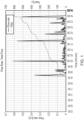
- Figure 1 illustrates example data from a flowmeter installed on an outlet pipe in a commercial kitchen that simultaneously takes waste water from two sinks.
- the graphs in Figure 1 show the dependence of monitored values of an immediate waste water flowrate and an accumulated, total waste water flow for the two sinks in dependence on the kitchen's operating time.
- the waste water flowrate is less than 0.05 l/s for most of the kitchen's operating time, and the discharged waste water accumulates to 600 I in 5.5 h.
- Figures 2a and 2b illustrate a cross-sectional side view and cross-sectional bottom view of the immiscible liquids separation apparatus 50 according to the embodiment of the invention, respectively.
- the immiscible liquids separation apparatus 50 comprises a vessel, an inlet 52, a low-density liquid (FOG) outlet 78, and a high-density liquid (water) outlet 60.
- the immiscible liquids separation apparatus 50 and / or its components may be made from metal, such as steel or stainless steel, or plastic, for example.
- the vessel comprises a first separation chamber 66 and second separation chamber 72.
- the vessel may be a housing 54.
- the vessel may comprise one or more lids, such as removable lids 55, 56.
- the first separation chamber 66 is situated above the second separation chamber 72.
- the first separation chamber 66 may comprise a coarse filtration chamber 62.
- the first separation chamber 66 may comprise a sloped bottom.
- the second separation chamber 72 is in first fluid communication with the first separation chamber 66.
- the vessel may further comprise a high-density liquid (water) release chamber 80.
- the high-density liquid (water) release chamber 80 may be in second fluid communication with the second separation chamber 72.
- the high-density liquid release chamber 80 may comprise a vertical release shaft 86 designed to allow the high-density liquid (water) flowing out of the vessel to take fine silt comprised in the liquid out of the vessel.
- the vessel may further comprise a container 58 arranged to collect the low-density liquid (FOG) removed from the second separation chamber 72.
- the vessel may further comprise a sloped plate 68 arranged to form a / the sloped bottom of the first separation chamber 66 and / or to form a sloped ceiling of the second separation chamber 72.
- the sloped bottom may comprise at least one hole 70 arranged at a low end of the sloped bottom to allow the first fluid communication at a first flow rate of the liquid (waste water).
- the vessel comprises a vertical low-density liquid (FOG) gap 75 arranged between the first separation chamber 66 and second separation chamber 72 to allow the first fluid communication at a second flow rate of the liquid, the second flow rate being higher than the first flow rate of the liquid.
- the vertical low-density liquid (FOG) gap 75 may comprise a coalescent filter, for example removable coalescent filter 88 to increase agglomeration of droplets of the low-density liquid (FOG).
- the inlet 52 is arranged at the first separation chamber 66 to allow a liquid (waste water) to flow into the vessel.
- the inlet 52 may be configured as a rotatable inlet, easing installation.
- the low-density liquid (FOG) outlet 78 is arranged on the second separation chamber 72 to allow low-density liquid (FOG) separated from the liquid (waste water) to be removed the second separation chamber 72.
- the vessel may further comprise a valve arranged at the low-density liquid (FOG) outlet 78 to enable or disable flow of the low-density liquid (FOG) out of the vessel.
- the valve may be a floating-ball valve 78 comprising a floating member configured to disable the flow of the low-density liquid (FOG) in case the high-density liquid (water) raises the floating member to a predetermined height.
- the high-density liquid (water) outlet 60 is arranged at the vessel to allow high-density liquid (water) separated from the liquid (waste water) to flow out of the vessel.
- the high-density liquid (water) outlet 60 may be arranged at the high-density (water) liquid release chamber 80.
- waste water comprising two or more immiscible liquids of different densities, such as water (high-density liquid) entrained with oil, grease, fats (low-density liquids) and /or other particles, flows into the inlet 52 providing a passage into the housing 54.
- the inlet 52 may be rotatable in order to ensure a variable connection in case of limited installation space in the kitchen.
- the immiscible liquids separate within the housing 54.
- the less-dense liquid (material) e. g. fat, oil and grease
- the more-dense liquid e. g. water
- Silt typically small particles of suspended solids, may accumulate at the bottom of housing 54. The silt may be periodically discharged through a silt outlet 57, if applicable.
- a coarse filtration chamber 62 is defined between the housing 54 and a perforated plate 63 that may extend across the full width of the housing 54.
- a filtering basket 64 filters out solid particles, such as food debris, undissolved fat and other suspended solids.
- the waste water After passing through the filtering basket 64, the waste water enters the first separation chamber 66, defined by a control plate 67, a sloped plate 68 and the housing 54. Both control plates 67 and 68 may extend across the full width of the housing 54. There are two exits from the first separation chamber 66: over an upper edge 69 and through holes 70, located at a lowest point of the first separation chamber 66. A sloped plate 68 is angled downward to holes 70. Small particles of suspended solids passing through the filtering basket 64 slide down the sloped plate 68 and fall through holes 70 to the bottom of the housing 54.
- the level of waste water in the first separation chamber 66 decreases to a level 74, which is at a same height as an outlet overflow edge 85.
- the waste water is not able to escape from the first separation chamber 66 only through the holes 70.
- the waste-water level rises up to the upper edge 69, and the waste water starts to overflow into the oil gap 75.
- the oil gap 75 is defined between the housing 54 and the control plate 67 with a free opening into the second separation chamber 72.
- the oil gap 75 keeps a specific amount of separated oil which can occupy the complete height of the oil gap 75. This condition supports agglomeration of oil droplets when the separated oil from free water level 73 and other oily water from the first separation chamber 66 flow through the oil gap 75.
- This coalescent effect may also be increased by inserting a coalescent filter, e. g. removable coalescent filter 88, into the oil gap 75.
- the waste water passing through the holes 70 and the oil gap 75 enters the second separation chamber 72 which is defined by the sloped plate 68, a control plate 76 and the bottom of the housing 54.
- the control plate 76 may extend across the full width of the housing 54.
- the sloped plate 68 is angled upward from the bottom of the first separation chamber 66 towards the floating-ball valve 78.
- a weir plate 82 which may extend across the full width of the housing 54, defines a water release chamber 80, along with the control plate 76 and the housing 54.
- the outlet 60 is disposed through the housing 54.
- the flow through the second separation chamber 72 is set at a rate that allows the oil to separate from the water and float upwards towards and touching the sloped plate 68, and then further float towards the floating-ball valve 78.
- the sloped plate 68 forces the oil to accumulate at the entry to floating-ball valve 78.
- the floating-ball valve 78 uses a ball that floats at the interface between the high-density liquid (water) and the low-density liquid (oil). When the high-density liquid reaches a predetermined height, the ball rises to height which stops oil flow from the second separation chamber 72 to the container 58.
- the water in the second separation chamber 72 attempts to rise to approximately the same height as the outlet overflow edge 85 is placed.
- a hydrostatic pressure of an upwards force of the water pushes the separated oil at the top of the second separation chamber 72 through the floating-ball valve 78.
- the water cannot pass through the floating-ball valve 78, because the floating-ball valve 78 will stop its passage.
- the floating-ball valve 78 remains closed until more oil accumulates.
- the separated water passes through the passage 79, over the weir plate 82 and through the outlet 60.
- the silt in the water tends to accumulate at the bottom of the housing 54.
- a silt valve 57 located at the bottom of housing 54, may be opened periodically, and a flow of water out of the silt valve 57 flushes the silt out of the second separation chamber 72.
- the waste-water flowrate from the sink can vary from less than 0.05 l/s to 2 l/s. As shown in Figure 1 , peak flowrates appear during kitchen operation several times per day. In these cases, a dynamic effect of high waste-water flowrate may be used to take silt from the bottom of the housing 54 away through the passage 79 and further through the vertical release shaft 86 between the control plate 76 and the weir plate 82. The higher the flowrate through the vertical release shaft 86 is, the greater the effect. At the flow velocity of 0.1 m/s through the vertical release shaft 86, fine silt is taken off and away, and discharged over the outlet overflow edge 85. In this case, the silt valve 57 may not need to be opened during daily maintenance.
- Figure 3 illustrates a detailed cross-sectional side view of the vertical low-density liquid gap 75 according to the embodiment of the invention.
- small low-density liquid droplets 83 i. e. small oil droplets
- the vertical low-density liquid gap 75 supports agglomeration of the low-density liquid droplets into compact low-density liquid layer that occupies the whole space between the control plate 67 and housing 54.
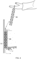
- Figure 4 illustrates a detailed cross-sectional side view of the vertical low-density liquid gap 75 according to the other embodiment of the invention.
- the coalescent filter is prone to clogging.
- the function of the vertical low-density liquid gap 75 may be improved by using a removable coalescent filter 88.
- the removable coalescent filter 88 may be removed from the vertical low-density liquid gap 75 and cleaned externally.
- the words “configured to " are used to mean that an element of an apparatus has a configuration able to carry out the defined operation.
- a “configuration” means an arrangement or manner of interconnection of hardware or software.
- the apparatus may have dedicated hardware which provides the defined operation, or a processor or other processing device may be programmed to perform the function.
- Configured to does not imply that the apparatus element needs to be changed in any way in order to provide the defined operation.
Landscapes
- Chemical & Material Sciences (AREA)
- Chemical Kinetics & Catalysis (AREA)
- Hydrology & Water Resources (AREA)
- Engineering & Computer Science (AREA)
- Water Supply & Treatment (AREA)
- Life Sciences & Earth Sciences (AREA)
- Thermal Sciences (AREA)
- Physics & Mathematics (AREA)
- Health & Medical Sciences (AREA)
- Public Health (AREA)
- Organic Chemistry (AREA)
- Environmental & Geological Engineering (AREA)
- Analytical Chemistry (AREA)
- Removal Of Floating Material (AREA)
- Physical Water Treatments (AREA)
- Ink Jet (AREA)
Applications Claiming Priority (2)
| Application Number | Priority Date | Filing Date | Title |
|---|---|---|---|
| GB1815872.5A GB2577559B (en) | 2018-09-28 | 2018-09-28 | Immiscible liquids separation apparatus and method |
| PCT/EP2019/075399 WO2020064571A1 (en) | 2018-09-28 | 2019-09-20 | Immiscible liquids separation apparatus and method |
Publications (2)
| Publication Number | Publication Date |
|---|---|
| EP3856983A1 EP3856983A1 (en) | 2021-08-04 |
| EP3856983B1 true EP3856983B1 (en) | 2023-11-01 |
Family
ID=68072353
Family Applications (1)
| Application Number | Title | Priority Date | Filing Date |
|---|---|---|---|
| EP19778903.5A Active EP3856983B1 (en) | 2018-09-28 | 2019-09-20 | Immiscible liquids separation apparatus and method |
Country Status (11)
| Country | Link |
|---|---|
| US (1) | US11377837B2 (pl) |
| EP (1) | EP3856983B1 (pl) |
| KR (1) | KR20210068072A (pl) |
| CN (1) | CN112752888B (pl) |
| AU (1) | AU2019345932B2 (pl) |
| DK (1) | DK3856983T3 (pl) |
| FI (1) | FI3856983T3 (pl) |
| GB (1) | GB2577559B (pl) |
| LT (1) | LT3856983T (pl) |
| PL (1) | PL3856983T3 (pl) |
| WO (1) | WO2020064571A1 (pl) |
Families Citing this family (1)
| Publication number | Priority date | Publication date | Assignee | Title |
|---|---|---|---|---|
| GB2599446A (en) * | 2020-10-05 | 2022-04-06 | Env Products & Services Limted | Waste water treatment apparatus |
Family Cites Families (19)
| Publication number | Priority date | Publication date | Assignee | Title |
|---|---|---|---|---|
| US1164527A (en) * | 1915-06-04 | 1915-12-14 | Kelly Separator Company | Grease-trap. |
| US3199676A (en) * | 1962-01-02 | 1965-08-10 | Briggs Filtration Company | Coalescing and filtering apparatus |
| JPS5421801Y2 (pl) * | 1976-07-12 | 1979-08-01 | ||
| US4422931A (en) * | 1982-04-15 | 1983-12-27 | Wolde Michael Girma | Oil concentrator |
| HU209763B (en) * | 1992-03-18 | 1994-10-28 | Szereday | Apparatus for separating first liquid contamination floating on fluid e.g. oil and the fluid e.g. water |
| US6517715B1 (en) * | 1999-11-12 | 2003-02-11 | Thermaco, Inc. | Readily serviceable separator unit with a focusing plate |
| EP1232779A1 (en) * | 2001-02-15 | 2002-08-21 | Evac International Oy | Separator device |
| US7285209B2 (en) * | 2001-12-28 | 2007-10-23 | Guanghua Yu | Method and apparatus for separating emulsified water from hydrocarbons |
| US7361282B2 (en) * | 2003-07-21 | 2008-04-22 | Smullin Corporation | Separator of floating components |
| US20080149553A1 (en) | 2004-03-26 | 2008-06-26 | Sowerby John C | separator for immiscible liquids |
| US7297284B2 (en) * | 2004-03-26 | 2007-11-20 | Goslyn, L.P. | Separator for immiscible liquids |
| US8153004B2 (en) * | 2008-11-14 | 2012-04-10 | Felix Juan Rodriguez-Jovet | Grease trap with detachable residue interceptor |
| US8915380B2 (en) * | 2009-12-24 | 2014-12-23 | Goslyn, LP | Separator for low discharge applications |
| US8273255B2 (en) * | 2010-06-04 | 2012-09-25 | Thermaco, Inc. | Economical fat, oil, and grease waste removal system and method |
| CN201704786U (zh) * | 2010-06-22 | 2011-01-12 | 刘克诚 | 餐饮废水油水分离装置 |
| GB2511292A (en) * | 2013-01-27 | 2014-09-03 | Edward George Owen | Semi Automatic Oil Water Separator |
| KR101634960B1 (ko) * | 2014-09-16 | 2016-07-01 | 삼성중공업 주식회사 | 선박용 오수 분리 장치 |
| US10035716B1 (en) * | 2015-08-21 | 2018-07-31 | Goslyn General, Llc | Immiscible liquid separator for marine vessels |
| CN207726772U (zh) * | 2017-09-28 | 2018-08-14 | 苏州美生环保科技有限公司 | 一种油水处理箱 |
-
2018
- 2018-09-28 GB GB1815872.5A patent/GB2577559B/en active Active
-
2019
- 2019-09-20 FI FIEP19778903.5T patent/FI3856983T3/fi active
- 2019-09-20 CN CN201980063168.8A patent/CN112752888B/zh active Active
- 2019-09-20 LT LTEPPCT/EP2019/075399T patent/LT3856983T/lt unknown
- 2019-09-20 KR KR1020217012414A patent/KR20210068072A/ko not_active Ceased
- 2019-09-20 AU AU2019345932A patent/AU2019345932B2/en active Active
- 2019-09-20 EP EP19778903.5A patent/EP3856983B1/en active Active
- 2019-09-20 US US17/279,833 patent/US11377837B2/en active Active
- 2019-09-20 DK DK19778903.5T patent/DK3856983T3/da active
- 2019-09-20 PL PL19778903.5T patent/PL3856983T3/pl unknown
- 2019-09-20 WO PCT/EP2019/075399 patent/WO2020064571A1/en not_active Ceased
Also Published As
| Publication number | Publication date |
|---|---|
| GB2577559B (en) | 2023-06-07 |
| LT3856983T (lt) | 2024-02-26 |
| US20210395992A1 (en) | 2021-12-23 |
| CN112752888A (zh) | 2021-05-04 |
| AU2019345932B2 (en) | 2022-02-10 |
| FI3856983T3 (fi) | 2024-02-01 |
| WO2020064571A1 (en) | 2020-04-02 |
| PL3856983T3 (pl) | 2024-05-13 |
| EP3856983A1 (en) | 2021-08-04 |
| KR20210068072A (ko) | 2021-06-08 |
| US11377837B2 (en) | 2022-07-05 |
| CN112752888B (zh) | 2022-07-15 |
| DK3856983T3 (da) | 2024-01-29 |
| AU2019345932A1 (en) | 2021-04-08 |
| GB2577559A (en) | 2020-04-01 |
Similar Documents
| Publication | Publication Date | Title |
|---|---|---|
| US4132645A (en) | Two-stage oil skimmer separator | |
| US5372718A (en) | Filtering device | |
| CA2785415C (en) | Separator for low discharge applications | |
| EP1697049B1 (en) | Grease separator for kitchen sinks and other applications | |
| WO2010050795A1 (en) | Kitchen wastewater treatment device | |
| US7431852B2 (en) | Oil/grease separator with interchangeable inlet and outlet | |
| US6629652B2 (en) | Kitchen sink disposer mount for space conservation | |
| JP5065567B2 (ja) | 固液分離装置 | |
| EP3856983B1 (en) | Immiscible liquids separation apparatus and method | |
| US20150183664A1 (en) | Automatic Rubber Belt Skimmer for Restaurant Wastewater FOG Interceptor | |
| US10300406B1 (en) | Variable flow immiscible liquid separator for in-ground applications | |
| JP2004081906A (ja) | 油脂を含む廃液が主成分の食品残滓から固形食品残滓と油脂を回収する処理システム。 | |
| RU160712U1 (ru) | Фильтрующий патрон для очистки сточных вод, размещаемый в канализационном колодце | |
| GB2565548A (en) | Apparatus for treating waste water | |
| CN219449399U (zh) | 一种油水分离系统 | |
| AU2019448170B2 (en) | Variable flow immiscible liquid separator for in-ground applications | |
| CA2866911C (en) | An outlet well cover for an in-line grease interceptor | |
| CN212769980U (zh) | 一种含油废水自动分离除油槽 | |
| KR101096795B1 (ko) | 조집기 | |
| EP1348475A2 (en) | Apparatus for filtering raw water such as surface water | |
| JPH06246108A (ja) | 重力式濾過装置 | |
| RU160669U1 (ru) | Фильтрующий патрон для очистки поверхностных сточных вод | |
| GB2551132A (en) | A grease separation apparatus | |
| IE20040570A1 (en) | A waste treatment system | |
| JP2001293306A (ja) | ドレントラップの接続構造 |
Legal Events
| Date | Code | Title | Description |
|---|---|---|---|
| STAA | Information on the status of an ep patent application or granted ep patent |
Free format text: STATUS: UNKNOWN |
|
| STAA | Information on the status of an ep patent application or granted ep patent |
Free format text: STATUS: THE INTERNATIONAL PUBLICATION HAS BEEN MADE |
|
| PUAI | Public reference made under article 153(3) epc to a published international application that has entered the european phase |
Free format text: ORIGINAL CODE: 0009012 |
|
| STAA | Information on the status of an ep patent application or granted ep patent |
Free format text: STATUS: REQUEST FOR EXAMINATION WAS MADE |
|
| 17P | Request for examination filed |
Effective date: 20210315 |
|
| AK | Designated contracting states |
Kind code of ref document: A1 Designated state(s): AL AT BE BG CH CY CZ DE DK EE ES FI FR GB GR HR HU IE IS IT LI LT LU LV MC MK MT NL NO PL PT RO RS SE SI SK SM TR |
|
| DAV | Request for validation of the european patent (deleted) | ||
| DAX | Request for extension of the european patent (deleted) | ||
| RAP3 | Party data changed (applicant data changed or rights of an application transferred) |
Owner name: ACO AHLMANN SE & CO. KG |
|
| GRAP | Despatch of communication of intention to grant a patent |
Free format text: ORIGINAL CODE: EPIDOSNIGR1 |
|
| STAA | Information on the status of an ep patent application or granted ep patent |
Free format text: STATUS: GRANT OF PATENT IS INTENDED |
|
| INTG | Intention to grant announced |
Effective date: 20230515 |
|
| GRAS | Grant fee paid |
Free format text: ORIGINAL CODE: EPIDOSNIGR3 |
|
| GRAA | (expected) grant |
Free format text: ORIGINAL CODE: 0009210 |
|
| STAA | Information on the status of an ep patent application or granted ep patent |
Free format text: STATUS: THE PATENT HAS BEEN GRANTED |
|
| AK | Designated contracting states |
Kind code of ref document: B1 Designated state(s): AL AT BE BG CH CY CZ DE DK EE ES FI FR GB GR HR HU IE IS IT LI LT LU LV MC MK MT NL NO PL PT RO RS SE SI SK SM TR |
|
| REG | Reference to a national code |
Ref country code: GB Ref legal event code: FG4D |
|
| REG | Reference to a national code |
Ref country code: CH Ref legal event code: EP |
|
| REG | Reference to a national code |
Ref country code: DE Ref legal event code: R096 Ref document number: 602019040640 Country of ref document: DE |
|
| REG | Reference to a national code |
Ref country code: IE Ref legal event code: FG4D |
|
| REG | Reference to a national code |
Ref country code: DK Ref legal event code: T3 Effective date: 20240125 |
|
| REG | Reference to a national code |
Ref country code: FI Ref legal event code: FGE |
|
| REG | Reference to a national code |
Ref country code: NL Ref legal event code: FP |
|
| REG | Reference to a national code |
Ref country code: SE Ref legal event code: TRGR |
|
| REG | Reference to a national code |
Ref country code: SK Ref legal event code: T3 Ref document number: E 43417 Country of ref document: SK |
|
| PG25 | Lapsed in a contracting state [announced via postgrant information from national office to epo] |
Ref country code: GR Free format text: LAPSE BECAUSE OF FAILURE TO SUBMIT A TRANSLATION OF THE DESCRIPTION OR TO PAY THE FEE WITHIN THE PRESCRIBED TIME-LIMIT Effective date: 20240202 |
|
| PG25 | Lapsed in a contracting state [announced via postgrant information from national office to epo] |
Ref country code: IS Free format text: LAPSE BECAUSE OF FAILURE TO SUBMIT A TRANSLATION OF THE DESCRIPTION OR TO PAY THE FEE WITHIN THE PRESCRIBED TIME-LIMIT Effective date: 20240301 |
|
| REG | Reference to a national code |
Ref country code: EE Ref legal event code: FG4A Ref document number: E024038 Country of ref document: EE Effective date: 20240130 |
|
| PG25 | Lapsed in a contracting state [announced via postgrant information from national office to epo] |
Ref country code: ES Free format text: LAPSE BECAUSE OF FAILURE TO SUBMIT A TRANSLATION OF THE DESCRIPTION OR TO PAY THE FEE WITHIN THE PRESCRIBED TIME-LIMIT Effective date: 20231101 |
|
| PG25 | Lapsed in a contracting state [announced via postgrant information from national office to epo] |
Ref country code: IS Free format text: LAPSE BECAUSE OF FAILURE TO SUBMIT A TRANSLATION OF THE DESCRIPTION OR TO PAY THE FEE WITHIN THE PRESCRIBED TIME-LIMIT Effective date: 20240301 Ref country code: GR Free format text: LAPSE BECAUSE OF FAILURE TO SUBMIT A TRANSLATION OF THE DESCRIPTION OR TO PAY THE FEE WITHIN THE PRESCRIBED TIME-LIMIT Effective date: 20240202 Ref country code: ES Free format text: LAPSE BECAUSE OF FAILURE TO SUBMIT A TRANSLATION OF THE DESCRIPTION OR TO PAY THE FEE WITHIN THE PRESCRIBED TIME-LIMIT Effective date: 20231101 Ref country code: BG Free format text: LAPSE BECAUSE OF FAILURE TO SUBMIT A TRANSLATION OF THE DESCRIPTION OR TO PAY THE FEE WITHIN THE PRESCRIBED TIME-LIMIT Effective date: 20240201 Ref country code: PT Free format text: LAPSE BECAUSE OF FAILURE TO SUBMIT A TRANSLATION OF THE DESCRIPTION OR TO PAY THE FEE WITHIN THE PRESCRIBED TIME-LIMIT Effective date: 20240301 |
|
| REG | Reference to a national code |
Ref country code: AT Ref legal event code: UEP Ref document number: 1627368 Country of ref document: AT Kind code of ref document: T Effective date: 20231101 |
|
| PG25 | Lapsed in a contracting state [announced via postgrant information from national office to epo] |
Ref country code: RS Free format text: LAPSE BECAUSE OF FAILURE TO SUBMIT A TRANSLATION OF THE DESCRIPTION OR TO PAY THE FEE WITHIN THE PRESCRIBED TIME-LIMIT Effective date: 20231101 Ref country code: HR Free format text: LAPSE BECAUSE OF FAILURE TO SUBMIT A TRANSLATION OF THE DESCRIPTION OR TO PAY THE FEE WITHIN THE PRESCRIBED TIME-LIMIT Effective date: 20231101 |
|
| PG25 | Lapsed in a contracting state [announced via postgrant information from national office to epo] |
Ref country code: SM Free format text: LAPSE BECAUSE OF FAILURE TO SUBMIT A TRANSLATION OF THE DESCRIPTION OR TO PAY THE FEE WITHIN THE PRESCRIBED TIME-LIMIT Effective date: 20231101 Ref country code: IT Free format text: LAPSE BECAUSE OF FAILURE TO SUBMIT A TRANSLATION OF THE DESCRIPTION OR TO PAY THE FEE WITHIN THE PRESCRIBED TIME-LIMIT Effective date: 20231101 |
|
| REG | Reference to a national code |
Ref country code: DE Ref legal event code: R097 Ref document number: 602019040640 Country of ref document: DE |
|
| P01 | Opt-out of the competence of the unified patent court (upc) registered |
Free format text: CASE NUMBER: APP_40350/2024 Effective date: 20240708 |
|
| PLBE | No opposition filed within time limit |
Free format text: ORIGINAL CODE: 0009261 |
|
| STAA | Information on the status of an ep patent application or granted ep patent |
Free format text: STATUS: NO OPPOSITION FILED WITHIN TIME LIMIT |
|
| 26N | No opposition filed |
Effective date: 20240802 |
|
| PG25 | Lapsed in a contracting state [announced via postgrant information from national office to epo] |
Ref country code: SI Free format text: LAPSE BECAUSE OF FAILURE TO SUBMIT A TRANSLATION OF THE DESCRIPTION OR TO PAY THE FEE WITHIN THE PRESCRIBED TIME-LIMIT Effective date: 20231101 |
|
| PG25 | Lapsed in a contracting state [announced via postgrant information from national office to epo] |
Ref country code: SI Free format text: LAPSE BECAUSE OF FAILURE TO SUBMIT A TRANSLATION OF THE DESCRIPTION OR TO PAY THE FEE WITHIN THE PRESCRIBED TIME-LIMIT Effective date: 20231101 |
|
| PG25 | Lapsed in a contracting state [announced via postgrant information from national office to epo] |
Ref country code: MC Free format text: LAPSE BECAUSE OF FAILURE TO SUBMIT A TRANSLATION OF THE DESCRIPTION OR TO PAY THE FEE WITHIN THE PRESCRIBED TIME-LIMIT Effective date: 20231101 |
|
| REG | Reference to a national code |
Ref country code: CH Ref legal event code: PL |
|
| PG25 | Lapsed in a contracting state [announced via postgrant information from national office to epo] |
Ref country code: LU Free format text: LAPSE BECAUSE OF NON-PAYMENT OF DUE FEES Effective date: 20240920 |
|
| PG25 | Lapsed in a contracting state [announced via postgrant information from national office to epo] |
Ref country code: CH Free format text: LAPSE BECAUSE OF NON-PAYMENT OF DUE FEES Effective date: 20240930 |
|
| PG25 | Lapsed in a contracting state [announced via postgrant information from national office to epo] |
Ref country code: IE Free format text: LAPSE BECAUSE OF NON-PAYMENT OF DUE FEES Effective date: 20240920 |
|
| PGFP | Annual fee paid to national office [announced via postgrant information from national office to epo] |
Ref country code: FI Payment date: 20250922 Year of fee payment: 7 |
|
| PGFP | Annual fee paid to national office [announced via postgrant information from national office to epo] |
Ref country code: DE Payment date: 20250919 Year of fee payment: 7 Ref country code: LT Payment date: 20250904 Year of fee payment: 7 Ref country code: DK Payment date: 20250922 Year of fee payment: 7 |
|
| PGFP | Annual fee paid to national office [announced via postgrant information from national office to epo] |
Ref country code: NO Payment date: 20250919 Year of fee payment: 7 |
|
| PGFP | Annual fee paid to national office [announced via postgrant information from national office to epo] |
Ref country code: NL Payment date: 20250922 Year of fee payment: 7 Ref country code: PL Payment date: 20250905 Year of fee payment: 7 |
|
| PGFP | Annual fee paid to national office [announced via postgrant information from national office to epo] |
Ref country code: BE Payment date: 20250919 Year of fee payment: 7 Ref country code: GB Payment date: 20250923 Year of fee payment: 7 |
|
| PGFP | Annual fee paid to national office [announced via postgrant information from national office to epo] |
Ref country code: FR Payment date: 20250925 Year of fee payment: 7 Ref country code: AT Payment date: 20250918 Year of fee payment: 7 |
|
| PGFP | Annual fee paid to national office [announced via postgrant information from national office to epo] |
Ref country code: SE Payment date: 20250922 Year of fee payment: 7 |
|
| PGFP | Annual fee paid to national office [announced via postgrant information from national office to epo] |
Ref country code: CZ Payment date: 20250905 Year of fee payment: 7 Ref country code: EE Payment date: 20250922 Year of fee payment: 7 |
|
| PGFP | Annual fee paid to national office [announced via postgrant information from national office to epo] |
Ref country code: SK Payment date: 20250910 Year of fee payment: 7 |
|
| PGFP | Annual fee paid to national office [announced via postgrant information from national office to epo] |
Ref country code: LV Payment date: 20250923 Year of fee payment: 7 |
|
| PG25 | Lapsed in a contracting state [announced via postgrant information from national office to epo] |
Ref country code: RO Free format text: LAPSE BECAUSE OF FAILURE TO SUBMIT A TRANSLATION OF THE DESCRIPTION OR TO PAY THE FEE WITHIN THE PRESCRIBED TIME-LIMIT Effective date: 20231101 |
|
| PG25 | Lapsed in a contracting state [announced via postgrant information from national office to epo] |
Ref country code: CY Free format text: LAPSE BECAUSE OF FAILURE TO SUBMIT A TRANSLATION OF THE DESCRIPTION OR TO PAY THE FEE WITHIN THE PRESCRIBED TIME-LIMIT; INVALID AB INITIO Effective date: 20190920 |
|
| PG25 | Lapsed in a contracting state [announced via postgrant information from national office to epo] |
Ref country code: HU Free format text: LAPSE BECAUSE OF FAILURE TO SUBMIT A TRANSLATION OF THE DESCRIPTION OR TO PAY THE FEE WITHIN THE PRESCRIBED TIME-LIMIT; INVALID AB INITIO Effective date: 20190920 |