EP3856312B1 - Humidifier with ingress protection for use in cpap therapy - Google Patents
Humidifier with ingress protection for use in cpap therapy Download PDFInfo
- Publication number
- EP3856312B1 EP3856312B1 EP19779828.3A EP19779828A EP3856312B1 EP 3856312 B1 EP3856312 B1 EP 3856312B1 EP 19779828 A EP19779828 A EP 19779828A EP 3856312 B1 EP3856312 B1 EP 3856312B1
- Authority
- EP
- European Patent Office
- Prior art keywords
- lid
- flow
- housing
- breathing gas
- disposed
- Prior art date
- Legal status (The legal status is an assumption and is not a legal conclusion. Google has not performed a legal analysis and makes no representation as to the accuracy of the status listed.)
- Active
Links
Images


Classifications
-
- A—HUMAN NECESSITIES
- A61—MEDICAL OR VETERINARY SCIENCE; HYGIENE
- A61M—DEVICES FOR INTRODUCING MEDIA INTO, OR ONTO, THE BODY; DEVICES FOR TRANSDUCING BODY MEDIA OR FOR TAKING MEDIA FROM THE BODY; DEVICES FOR PRODUCING OR ENDING SLEEP OR STUPOR
- A61M16/00—Devices for influencing the respiratory system of patients by gas treatment, e.g. ventilators; Tracheal tubes
- A61M16/10—Preparation of respiratory gases or vapours
- A61M16/14—Preparation of respiratory gases or vapours by mixing different fluids, one of them being in a liquid phase
- A61M16/16—Devices to humidify the respiration air
- A61M16/162—Water-reservoir filling system, e.g. automatic
-
- A—HUMAN NECESSITIES
- A61—MEDICAL OR VETERINARY SCIENCE; HYGIENE
- A61M—DEVICES FOR INTRODUCING MEDIA INTO, OR ONTO, THE BODY; DEVICES FOR TRANSDUCING BODY MEDIA OR FOR TAKING MEDIA FROM THE BODY; DEVICES FOR PRODUCING OR ENDING SLEEP OR STUPOR
- A61M16/00—Devices for influencing the respiratory system of patients by gas treatment, e.g. ventilators; Tracheal tubes
- A61M16/0057—Pumps therefor
- A61M16/0066—Blowers or centrifugal pumps
-
- A—HUMAN NECESSITIES
- A61—MEDICAL OR VETERINARY SCIENCE; HYGIENE
- A61M—DEVICES FOR INTRODUCING MEDIA INTO, OR ONTO, THE BODY; DEVICES FOR TRANSDUCING BODY MEDIA OR FOR TAKING MEDIA FROM THE BODY; DEVICES FOR PRODUCING OR ENDING SLEEP OR STUPOR
- A61M16/00—Devices for influencing the respiratory system of patients by gas treatment, e.g. ventilators; Tracheal tubes
- A61M16/10—Preparation of respiratory gases or vapours
- A61M16/14—Preparation of respiratory gases or vapours by mixing different fluids, one of them being in a liquid phase
- A61M16/16—Devices to humidify the respiration air
-
- A—HUMAN NECESSITIES
- A61—MEDICAL OR VETERINARY SCIENCE; HYGIENE
- A61M—DEVICES FOR INTRODUCING MEDIA INTO, OR ONTO, THE BODY; DEVICES FOR TRANSDUCING BODY MEDIA OR FOR TAKING MEDIA FROM THE BODY; DEVICES FOR PRODUCING OR ENDING SLEEP OR STUPOR
- A61M16/00—Devices for influencing the respiratory system of patients by gas treatment, e.g. ventilators; Tracheal tubes
- A61M16/0057—Pumps therefor
- A61M16/0066—Blowers or centrifugal pumps
- A61M16/0069—Blowers or centrifugal pumps the speed thereof being controlled by respiratory parameters, e.g. by inhalation
-
- A—HUMAN NECESSITIES
- A61—MEDICAL OR VETERINARY SCIENCE; HYGIENE
- A61M—DEVICES FOR INTRODUCING MEDIA INTO, OR ONTO, THE BODY; DEVICES FOR TRANSDUCING BODY MEDIA OR FOR TAKING MEDIA FROM THE BODY; DEVICES FOR PRODUCING OR ENDING SLEEP OR STUPOR
- A61M2205/00—General characteristics of the apparatus
- A61M2205/21—General characteristics of the apparatus insensitive to tilting or inclination, e.g. spill-over prevention
Definitions
- the present invention pertains to humidifiers for use in airway pressure support systems for delivering a flow of a humidified gas to the airway of a patient and, more particularly to arrangements for preventing the passage of water outward from the inlet of such humidifiers.
- sleep apnea is a common example of such sleep disordered breathing suffered by millions of people throughout the world.
- One type of sleep apnea is obstructive sleep apnea (OSA), which is a condition in which sleep is repeatedly interrupted by an inability to breathe due to an obstruction of the airway; typically the upper airway or pharyngeal area. Obstruction of the airway is generally believed to be due, at least in part, to a general relaxation of the muscles which stabilize the upper airway segment, thereby allowing the tissues to collapse the airway.
- OSA obstructive sleep apnea
- sleep apnea syndrome is a central apnea, which is a cessation of respiration due to the absence of respiratory signals from the brain's respiratory center.
- An apnea condition whether obstructive, central, or mixed, which is a combination of obstructive and central, is defined as the complete or near cessation of breathing, for example a 90% or greater reduction in peak respiratory air-flow.
- sleep apnea Those afflicted with sleep apnea experience sleep fragmentation and complete or nearly complete cessation of ventilation intermittently during sleep with potentially severe degrees of oxyhemoglobin desaturation. These symptoms may be translated clinically into extreme daytime sleepiness, cardiac arrhythmias, pulmonary-artery hypertension, congestive heart failure and/or cognitive dysfunction. Other consequences of sleep apnea include right ventricular dysfunction, carbon dioxide retention during wakefulness, as well as during sleep, and continuous reduced arterial oxygen tension. Sleep apnea sufferers may be at risk for excessive mortality from these factors as well as by an elevated risk for accidents while driving and/or operating potentially dangerous equipment.
- a hypopnea is typically defined as a 50% or greater reduction in the peak respiratory air-flow.
- Other types of sleep disordered breathing include, without limitation, upper airway resistance syndrome (UARS) and vibration of the airway, such as vibration of the pharyngeal wall, commonly referred to as snoring.
- UARS upper airway resistance syndrome
- snoring vibration of the airway
- CPAP continuous positive air pressure
- This positive pressure effectively "splints" the airway, thereby maintaining an open passage to the lungs.
- CPAP continuous positive air pressure
- This pressure support technique is referred to as bi-level pressure support, in which the inspiratory positive airway pressure (IPAP) delivered to the patient is higher than the expiratory positive airway pressure (EPAP).
- This pressure support technique is referred to as an auto-titration type of pressure support, because the pressure support device seeks to provide a pressure to the patient that is only as high as necessary to treat the disordered breathing.
- Pressure support therapies as just described involve the placement of a patient interface device including a mask component having a soft, flexible sealing cushion on the face of the patient.
- the mask component may be, without limitation, a nasal mask that covers the patient's nose, a nasal/oral mask that covers the patient's nose and mouth, or a full face mask that covers the patient's face.
- Such patient interface devices may also employ other patient contacting components, such as forehead supports, cheek pads and chin pads.
- the patient interface device is typically secured to the patient's head by a headgear component.
- the patient interface device is connected to a gas delivery tube or conduit and interfaces the pressure support device with the airway of the patient, so that a flow of breathing gas can be delivered from the pressure/flow generating device to the airway of the patient.
- Humidifiers are frequently provided between or integral with a PAP machine and the user interface in order to humidify the otherwise relatively-dry compressed air generated by the PAP machine.
- the most conventional type of humidification used in homecare ventilation is a passover arrangement. In such arrangement, air from the CPAP machine flows into a water chamber and over an area of water W before exiting the humidifier and passing on to the patient. This carries the moisture via a patient circuit (tubing + mask) to the patient.
- the water can be at room temperature or at an elevated temperature.
- the elevated temperate approach is more popular because it delivers more water in the air due to the fact that it is heated.
- the water for this type of humidifier is commonly heated using a resistive heater and has multiple set points for comfort.
- US 5 511 539 A discloses a dose inhaler which comprises a cover lid, a channel lid, a water chamber, a power set and a bottom wherein the power set includes a housing, an oscillator and a circuit.
- the housing which is disposed with the circuit is installed at the bottom.
- WO 2014/138804 A1 discloses a reservoir configured to retain a volume of liquid for use in an apparatus for humidifying a flow of pressurized air.
- the reservoir comprises a base portion and a lid portion.
- Embodiments of the present invention minimize or eliminate the potential for such water ingress to the flow generator while allowing for the water chamber to be filled while the water chamber is still installed in the humidifier and attached to the flow generator.
- Embodiments of the invention routes the airway path generally through a pivoting point of the water chamber lid which when raised, positions the outlet from the above the water chamber and therefore eliminates the possibility of water entering the flow generator.
- an apparatus for providing a flow of breathing gas for a patient comprises: a housing; a gas flow generator disposed in the housing, the gas flow generator structured to generate the flow of breathing gas; a humidifier disposed in the housing, the humidifier having a water chamber structured to house a volume of water therein, the water chamber having a top opening for providing the volume of water in the chamber; a lid coupled to the housing such that the lid is movable between a first position wherein the lid covers the top opening of the water chamber and a second position wherein the lid does not cover the top opening of the water chamber; a passage which extends from a first end positioned and structured to receive the flow of breathing gas from the gas flow generator to an opposite second end positioned on the lid and structured to expel the flow of breathing gas into the chamber; and an outlet positioned on the housing, the outlet being structured to convey the flow of breathing gas from the chamber out of the housing and the lid is rotatably coupled to the housing via a hinge arrangement such that the lid
- the hinge arrangement may comprise a generally cylindrical portion disposed about the rotational axis; the portion may comprise a hollow defined in the cylindrical portion.
- the hollow may extend from an inlet which is positioned to initially receive the flow of breathing gas entering the hollow; and the inlet may be disposed on an axial face of the cylindrical portion.
- the hollow may extend from an inlet which is positioned to initially receive the flow of breathing gas entering the hollow; and wherein the inlet is disposed on a circumferential face of the cylindrical portion.
- the inlet When the lid is disposed in the first position the inlet may be positioned to receive the flow of breathing gas; and when the lid is disposed in the second position the inlet may be positioned to not receive the flow of breathing gas.
- the cylindrical portion may be fixedly coupled to the lid.
- the hollow may extend from an inlet to a side outlet; and the portion may further comprise a generally straight section which extends from the side outlet to the opposite second end of passage.
- the lid may comprise an inner lid and the apparatus may further comprise an outer lid coupled to the housing such that the outer lid is movable between a first position wherein the outer lid covers the inner lid and a second position wherein the outer lid does not cover the inner lid.
- the housing may comprise a first housing and a second housing selectively coupled to the first housing; and the gas flow generator may be disposed in the first housing and the humidifier may be disposed in the second housing.
- an airway pressure support system for providing a flow of breathing gas to the airway of a patient.
- the system comprises an apparatus for providing a flow of breathing gas for a patient, the apparatus comprising: a housing; a gas flow generator disposed in the housing, the gas flow generator structured to generate the flow of breathing gas; a humidifier disposed in the housing, the humidifier having a water chamber structured to house a volume of water therein, the water chamber having a top opening for providing the volume of water in the chamber; a lid coupled to the housing such that the lid is movable between a first position wherein the lid covers the top opening of the water chamber and a second position wherein the lid does not cover the top opening of the water chamber; a passage which extends from a first end positioned and structured to receive the flow of breathing gas from the gas flow generator to an opposite second end positioned on the lid and structured to expel the flow of breathing gas into the chamber; and an outlet positioned on the housing, the outlet being structured to convey the flow of breathing gas from
- the system further comprises: a delivery conduit having a first end coupled to the outlet of the apparatus and an opposite second end, the conduit being structured to convey the flow of breathing gas from the first end to the second end; and a patient interface device coupled to the second end of the conduit for providing the flow of breathing gas to an airway of the patient.
- the word "unitary” means a component is created as a single piece or unit. That is, a component that includes pieces that are created separately and then coupled together as a unit is not a “unitary” component or body.
- the statement that two or more parts or components "engage” one another shall mean that the parts exert a force against one another either directly or through one or more intermediate parts or components.
- the term “number” shall mean one or an integer greater than one (i.e., a plurality).
- FIG. 1 is a schematic diagram of an airway pressure support system 2 according to one particular, non-limiting embodiment in which the present invention in its various embodiments may be implemented.
- Pressure support system 2 includes an apparatus 4 for providing a flow of breathing gas, a delivery conduit 6 for communicating the flow of breathing gas, a patient interface device 8 structured to receive the flow of breathing gas from conduit 6 and engage about an airway of the patient, and a headgear 10 for securing patient interface device 8 to the head of a patient (P).
- Apparatus 4 includes a gas flow generator 12 which is structured to generate the flow of breathing gas to be delivered through patient interface device 8 to the airway of patient P.
- the flow of breathing gas may be heated and/or humidified by a humidifier 14 provided as a portion of apparatus 4.
- Gas flow generator 12 and humidifier 14 may be: provided in a common or main housing 17, or provided in separate housings 18, 20 which may be selectively coupled and uncoupled with each other via any suitable coupling arrangement.
- Gas flow generator 12 may include, without limitation, ventilators, constant pressure support devices (such as a continuous positive airway pressure device, or CPAP device), variable pressure devices (e.g., BiPAP ® , Bi-Flex ® , or C-Flex TM devices manufactured and distributed by Philips Respironics of Murrysville, Pennsylvania), and auto-titration pressure support devices.
- Delivery conduit 6 is structured to communicate the flow of breathing gas from apparatus 4 to patient interface device 8. Delivery conduit 6 and patient interface device 8 are often collectively referred to as a patient circuit.
- a BiPAP ® device is a bi-level device in which the pressure provided to the patient varies with the patient's respiratory cycle, so that a higher pressure is delivered during inspiration than during expiration.
- An auto-titration pressure support system is a system in which the pressure varies with the condition of the patient, such as whether the patient is snoring or experiencing an apnea or hypopnea.
- gas flow generator 12 is any conventional system for delivering a flow of gas to an airway of a patient or for elevating a pressure of gas at an airway of the patient, including the pressure support systems summarized above and non-invasive ventilation systems.
- patient interface device 8 includes a patient sealing assembly 16, which in the illustrated embodiment is a full face mask. It is to be appreciated, however, that other types of patient sealing assemblies, such as, without limitation, a nasal/oral mask, a nasal cushion, or any other arrangements which facilitate the delivery of the flow of breathing gas to the airway of a patient may be substituted for patient sealing assembly 16 while remaining within the scope of the present invention. It is also to be appreciated that headgear 10 is provided solely for exemplary purposes and that any suitable headgear arrangement may be employed without varying from the scope of the present invention.
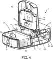
- apparatus 4 generally includes a gas flow generator 12 ( FIGS. 4 and 5 ) and a humidifier 14 positioned in a main housing 17.
- Gas flow generator 12 is structured to generate the flow (shown schematically by arrows F) of breathing gas and humidifier 14 is structured to humidify the flow of breathing gas produced by gas flow generator.
- humidifier 14 includes a water chamber 30 which is structured to house a volume of water W therein.
- Water chamber 30 is generally accessible via a top opening 32 via which volume of water W may be provided (e.g., via a water faucet, pitcher, etc.) in chamber 30, as-needed, by a user of apparatus 4.
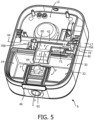
- Access to to opening 32 is governed by an inner lid 40 coupled to housing 17, so as to move as movable portion thereof. Accordingly, lid 40 is movable between a first position ( FIGS. 1 , 5 and 6 ) wherein inner lid 40 covers top opening 32 of water chamber 30, and a second position ( FIGS. 3 and 4 ) wherein inner lid 40 does not cover top opening 32 of water chamber 30.
- inner lid 40 is rotatably coupled to housing 17 via a hinge arrangement 42 so as to rotate about a rotational axis 44.
- Inner lid 40 may include a latch mechanism 46 generally opposite the portion thereof which is coupled to housing 17, for use in reliably securing inner lid 40 in the aforementioned first position to housing 17, such as generally shown in FIGS. 2 and 6 .
- an outer lid 50 may further be provided which is coupled to housing 17 such that outer lid 50 is movable between a first position ( FIGS. 2 , 5 and 6 ) wherein outer lid 50 covers inner lid 40, and a second position ( FIGS. 3 and 4 ) wherein outer lid 50 does not cover inner lid 40.
- outer lid 50 is rotatably coupled to housing 17 so as to rotate about a second rotational axis (not numbered) disposed generally parallel to rotational axis 44.
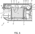
- passage 60 which extends from a first end (shown generally at 62 in FIG. 4 ) which is positioned and structured to receive the flow F of breathing gas from gas flow generator 12, to an opposite second end 64 which is disposed on inner lid 40 and which is positioned and structured to expel the flow F of breathing gas into chamber 30 of humidifier 14.
- passage 60 generally includes two portions: i) a first portion 60A ( FIG. 4 ) defined generally by housing 17 and internal components (not numbered) of apparatus 4; and ii) a second portion 60B ( FIGS. 5 and 6 ) defined generally by hinge arrangement 42 and inner lid 40.
- hinge arrangement 42 includes a generally cylindrical portion 70 to which inner lid 40 is fixedly coupled.
- Cylindrical portion 70 is disposed about rotational axis 44, such that the central longitudinal axis of cylindrical portion 70 coincides with rotational axis 44.
- Cylindrical portion 70 is coupled at or about opposing ends 70A, 70B to housing 17 such that cylindrical portion 70 (as well as inner lid 40) is rotatable about rotational axis 44.
- Cylindrical portion 70 includes a hollow 72 defined therein which extends from an inlet 74 disposed at or about first end 70A, toward a second end 70B of cylindrical portion 70, and ends at a side outlet 76 which is disposed generally parallel to rotational axis 44.
- inlet 74 is defined in an axial face (not numbered) at first end 70A such that the flow F of breathing gas enters hollow 72 generally axially along rotational axis 44. In such arrangement, inlet 74 is always "open", regardless of the rotational positioning of cylindrical portion 70.
- FIGS. 7A and 7B illustrate a sectional view of another example embodiment in which inlet 74 is defined in a circumferential face (not numbered) of cylindrical portion 70' (and the axial face is closed). In such arrangement, when cylindrical portion 70' (as well as inner lid 40) is positioned in a "closed" position, such as shown in FIG.
- inlet 74 is positioned to receive the flow F of breathing gas.
- cylindrical portion 70' (as well as inner lid 40) is positioned in an "open" position (e.g., via rotation of inner lid 40 and cylindrical portion 70' about 90° in the direction R), such as shown in FIG. 7B , inlet 74 is covered, thus preventing passage of fluids (e.g., flow F, water) in either direction through inlet 74.
- the arrangement of hinge arrangement 42 may be generally reversed (i.e., cylindrical portions 70, 70' fixedly coupled to housing 17 and providing flow to a passage on inner lid 40 via inlet 74) without varying from the scope of the present concept.
- other arrangements which provide for a passage from gas flow generator 12 to an outlet positioned on a portion of inner lid 40 similarly to outlet 64 may be employed without varying from the scope of the present invention.
- second portion 60B of passage 60 further includes a generally straight section 80 which extends along an underside (not numbered) inner lid 40 from side outlet 76 of cylindrical portion 70 and terminates at opposite second end 64.
- Outlet 92 is positioned on an exterior of housing 17 and is structured such that a conduit, such as conduit 6, previously discussed in conjunction with FIG. 1 , may be readily coupled thereto for further communicating the now humidified flow F of breathing gas to a patient interface device engaged with an airway of a patient.
- embodiments of the present invention provide arrangements which allow for a water chamber of a humidifier to be filled/refilled while such chamber is installed in a CPAP apparatus with minimal chance of water ingress to the flow generating device.
- any reference signs placed between parentheses shall not be construed as limiting the claim.
- the word “comprising” or “including” does not exclude the presence of elements or steps other than those listed in a claim.
- several of these means may be embodied by one and the same item of hardware.
- the word “a” or “an” preceding an element does not exclude the presence of a plurality of such elements.
- any device claim enumerating several means several of these means may be embodied by one and the same item of hardware.
- the mere fact that certain elements are recited in mutually different dependent claims does not indicate that these elements cannot be used in combination.
Landscapes
- Health & Medical Sciences (AREA)
- Emergency Medicine (AREA)
- Pulmonology (AREA)
- Engineering & Computer Science (AREA)
- Anesthesiology (AREA)
- Biomedical Technology (AREA)
- Heart & Thoracic Surgery (AREA)
- Hematology (AREA)
- Life Sciences & Earth Sciences (AREA)
- Animal Behavior & Ethology (AREA)
- General Health & Medical Sciences (AREA)
- Public Health (AREA)
- Veterinary Medicine (AREA)
- Respiratory Apparatuses And Protective Means (AREA)
- Air Humidification (AREA)
Applications Claiming Priority (2)
| Application Number | Priority Date | Filing Date | Title |
|---|---|---|---|
| US201862738376P | 2018-09-28 | 2018-09-28 | |
| PCT/EP2019/075986 WO2020064906A1 (en) | 2018-09-28 | 2019-09-26 | Humidifier with ingress protection for use in cpap therapy |
Publications (2)
| Publication Number | Publication Date |
|---|---|
| EP3856312A1 EP3856312A1 (en) | 2021-08-04 |
| EP3856312B1 true EP3856312B1 (en) | 2025-03-19 |
Family
ID=68104609
Family Applications (1)
| Application Number | Title | Priority Date | Filing Date |
|---|---|---|---|
| EP19779828.3A Active EP3856312B1 (en) | 2018-09-28 | 2019-09-26 | Humidifier with ingress protection for use in cpap therapy |
Country Status (5)
| Country | Link |
|---|---|
| US (1) | US11484682B2 (https=) |
| EP (1) | EP3856312B1 (https=) |
| JP (1) | JP7397860B2 (https=) |
| CN (1) | CN112770802B (https=) |
| WO (1) | WO2020064906A1 (https=) |
Families Citing this family (8)
| Publication number | Priority date | Publication date | Assignee | Title |
|---|---|---|---|---|
| EP4079363B1 (en) * | 2013-03-15 | 2025-08-27 | ResMed Pty Ltd | Respiratory pressure device |
| CN119215295A (zh) | 2018-10-26 | 2024-12-31 | 北京怡和嘉业医疗科技股份有限公司 | 加湿组件和呼吸通气设备 |
| USD928962S1 (en) * | 2019-04-16 | 2021-08-24 | Perma Pure Llc | Humidifier base for low-flow oxygen therapy |
| USD948055S1 (en) * | 2019-04-16 | 2022-04-05 | Perma Pure Llc | Humidifier cartridge for low-flow oxygen therapy |
| USD936833S1 (en) * | 2019-04-16 | 2021-11-23 | Perma Pure Llc | Humidifier for low-flow oxygen therapy |
| CN116370777B (zh) * | 2019-04-17 | 2026-04-03 | 瑞思迈私人有限公司 | Cpap系统 |
| WO2021002091A1 (ja) * | 2019-07-04 | 2021-01-07 | 株式会社村田製作所 | 呼吸器用送風装置 |
| USD1088216S1 (en) * | 2021-11-23 | 2025-08-12 | Hl Mando Corporation | Continuous positive airway pressure device |
Family Cites Families (24)
| Publication number | Priority date | Publication date | Assignee | Title |
|---|---|---|---|---|
| US3667463A (en) * | 1969-11-14 | 1972-06-06 | David L Barnes | Method and apparatus for treatment of respiratory disease |
| US5645769A (en) * | 1994-06-17 | 1997-07-08 | Nippondenso Co., Ltd. | Humidified cool wind system for vehicles |
| US5511539A (en) | 1995-06-19 | 1996-04-30 | Lien; Su-Chu | Dose inhaler |
| DE10016005B4 (de) * | 2000-03-31 | 2007-11-22 | Map Medizin-Technologie Gmbh | Vorrichtung zur Atemgasbefeuchtung |
| WO2002066106A1 (en) | 2001-02-16 | 2002-08-29 | Resmed Limited | Humidifier with structure to prevent backflow of liquid through the humidifier inlet |
| DE202004021798U1 (de) * | 2003-06-20 | 2011-02-10 | ResMed Ltd., Bella Vista | Atemgasvorrichtung mit Befeuchter |
| JP2005287596A (ja) * | 2004-03-31 | 2005-10-20 | Teijin Pharma Ltd | 呼吸用気体供給装置 |
| DE102004052054A1 (de) * | 2004-10-26 | 2006-04-27 | Map Medizin-Technologie Gmbh | Vorrichtung zur Verabreichung eines atembaren Gases sowie Komponenten derselben |
| US20070035044A1 (en) * | 2005-08-15 | 2007-02-15 | Paul Chiu | Humidifier having a night lamp function |
| KR101311751B1 (ko) * | 2005-08-23 | 2013-09-26 | 노바르티스 아게 | 자기밀봉식 t 부품 및 밸브형 t 부품 |
| US8985105B2 (en) * | 2005-10-21 | 2015-03-24 | Compumedics Medical Innovation Pty Ltd | Apparatus for delivery of pressurised gas |
| EP3372266B1 (en) * | 2006-10-02 | 2020-01-01 | Philip Morris Products S.a.s. | Continuous high pressure delivery system |
| US20080093750A1 (en) * | 2006-10-18 | 2008-04-24 | Zhijing Wang | Dual inlet water tank for a humidifier |
| WO2009099995A1 (en) | 2008-02-01 | 2009-08-13 | Ventus Medical, Inc. | Cpap interface and backup devices |
| US8453640B2 (en) | 2008-11-12 | 2013-06-04 | Resmed Limited | Positive airway pressure device |
| US9737682B2 (en) | 2009-09-17 | 2017-08-22 | Resmed Limited | Humidification of respiratory gases |
| US8757154B2 (en) * | 2011-08-09 | 2014-06-24 | Carmen Schuller | Air purifier apparatus |
| WO2013040198A2 (en) | 2011-09-13 | 2013-03-21 | Resmed Limited | Vent arrangement for respiratory mask |
| US10213573B2 (en) | 2011-12-22 | 2019-02-26 | Resmed Limited | Humidifiers for respiratory apparatus |
| EP2844327A1 (en) | 2012-05-01 | 2015-03-11 | Koninklijke Philips N.V. | System and method for controlling flow during exhalation in a respiratory support system |
| US9861778B2 (en) | 2013-03-15 | 2018-01-09 | Resmed Limited | Humidifier reservoir |
| EP4079363B1 (en) * | 2013-03-15 | 2025-08-27 | ResMed Pty Ltd | Respiratory pressure device |
| JP6515096B2 (ja) | 2013-06-28 | 2019-05-15 | コーニンクレッカ フィリップス エヌ ヴェKoninklijke Philips N.V. | 圧補助システムにおいて供給される気体を加湿する加湿器アセンブリ及び方法 |
| KR101685901B1 (ko) * | 2016-07-15 | 2016-12-13 | 최연옥 | 휴대용 공기정화기 |
-
2019
- 2019-09-25 US US16/582,218 patent/US11484682B2/en active Active
- 2019-09-26 WO PCT/EP2019/075986 patent/WO2020064906A1/en not_active Ceased
- 2019-09-26 CN CN201980062583.1A patent/CN112770802B/zh active Active
- 2019-09-26 EP EP19779828.3A patent/EP3856312B1/en active Active
- 2019-09-26 JP JP2021516780A patent/JP7397860B2/ja active Active
Also Published As
| Publication number | Publication date |
|---|---|
| US11484682B2 (en) | 2022-11-01 |
| EP3856312A1 (en) | 2021-08-04 |
| JP2022502152A (ja) | 2022-01-11 |
| CN112770802B (zh) | 2024-09-10 |
| CN112770802A (zh) | 2021-05-07 |
| JP7397860B2 (ja) | 2023-12-13 |
| WO2020064906A1 (en) | 2020-04-02 |
| US20200101258A1 (en) | 2020-04-02 |
Similar Documents
| Publication | Publication Date | Title |
|---|---|---|
| EP3856312B1 (en) | Humidifier with ingress protection for use in cpap therapy | |
| US10737052B2 (en) | Fluid coupling member including valve member | |
| EP3013401B1 (en) | Humidifier assembly and method of providing moisture to supplied gas in a pressure support system. | |
| EP3600510B1 (en) | Moisture wicking conduit and system cross-reference to related applications | |
| EP3731914B1 (en) | Humidifier and airway pressure support system including same | |
| EP3856313B1 (en) | Humidifier with ingress protection for use in cpap therapy | |
| US20190201652A1 (en) | Humidifier and airway pressure support system including same | |
| US12515003B2 (en) | Customizable mask and method of sizing | |
| JP6938792B2 (ja) | 加湿器及びこれを含む気道内圧サポートシステム | |
| WO2013144740A1 (en) | Selectable exhaust port assembly | |
| US12097326B2 (en) | Patient interface having a restrictor element for varying flow resistance through an exhalation port thereof | |
| EP3731910B1 (en) | System for operating a pump in a humidifier | |
| US12161802B2 (en) | Compact fluid moving assembly and device employing same |
Legal Events
| Date | Code | Title | Description |
|---|---|---|---|
| STAA | Information on the status of an ep patent application or granted ep patent |
Free format text: STATUS: UNKNOWN |
|
| STAA | Information on the status of an ep patent application or granted ep patent |
Free format text: STATUS: THE INTERNATIONAL PUBLICATION HAS BEEN MADE |
|
| PUAI | Public reference made under article 153(3) epc to a published international application that has entered the european phase |
Free format text: ORIGINAL CODE: 0009012 |
|
| STAA | Information on the status of an ep patent application or granted ep patent |
Free format text: STATUS: REQUEST FOR EXAMINATION WAS MADE |
|
| 17P | Request for examination filed |
Effective date: 20210428 |
|
| AK | Designated contracting states |
Kind code of ref document: A1 Designated state(s): AL AT BE BG CH CY CZ DE DK EE ES FI FR GB GR HR HU IE IS IT LI LT LU LV MC MK MT NL NO PL PT RO RS SE SI SK SM TR |
|
| DAV | Request for validation of the european patent (deleted) | ||
| DAX | Request for extension of the european patent (deleted) | ||
| STAA | Information on the status of an ep patent application or granted ep patent |
Free format text: STATUS: EXAMINATION IS IN PROGRESS |
|
| 17Q | First examination report despatched |
Effective date: 20240411 |
|
| REG | Reference to a national code |
Ref country code: DE Ref legal event code: R079 Ref document number: 602019067506 Country of ref document: DE Free format text: PREVIOUS MAIN CLASS: A61M0016160000 Ipc: A61M0016000000 |
|
| GRAP | Despatch of communication of intention to grant a patent |
Free format text: ORIGINAL CODE: EPIDOSNIGR1 |
|
| STAA | Information on the status of an ep patent application or granted ep patent |
Free format text: STATUS: GRANT OF PATENT IS INTENDED |
|
| RIC1 | Information provided on ipc code assigned before grant |
Ipc: A61M 16/20 20060101ALI20241001BHEP Ipc: A61M 16/16 20060101ALI20241001BHEP Ipc: A61M 16/00 20060101AFI20241001BHEP |
|
| INTG | Intention to grant announced |
Effective date: 20241017 |
|
| GRAS | Grant fee paid |
Free format text: ORIGINAL CODE: EPIDOSNIGR3 |
|
| GRAA | (expected) grant |
Free format text: ORIGINAL CODE: 0009210 |
|
| STAA | Information on the status of an ep patent application or granted ep patent |
Free format text: STATUS: THE PATENT HAS BEEN GRANTED |
|
| AK | Designated contracting states |
Kind code of ref document: B1 Designated state(s): AL AT BE BG CH CY CZ DE DK EE ES FI FR GB GR HR HU IE IS IT LI LT LU LV MC MK MT NL NO PL PT RO RS SE SI SK SM TR |
|
| REG | Reference to a national code |
Ref country code: GB Ref legal event code: FG4D |
|
| REG | Reference to a national code |
Ref country code: CH Ref legal event code: EP |
|
| REG | Reference to a national code |
Ref country code: IE Ref legal event code: FG4D |
|
| REG | Reference to a national code |
Ref country code: DE Ref legal event code: R096 Ref document number: 602019067506 Country of ref document: DE |
|
| PG25 | Lapsed in a contracting state [announced via postgrant information from national office to epo] |
Ref country code: RS Free format text: LAPSE BECAUSE OF FAILURE TO SUBMIT A TRANSLATION OF THE DESCRIPTION OR TO PAY THE FEE WITHIN THE PRESCRIBED TIME-LIMIT Effective date: 20250619 |
|
| PG25 | Lapsed in a contracting state [announced via postgrant information from national office to epo] |
Ref country code: FI Free format text: LAPSE BECAUSE OF FAILURE TO SUBMIT A TRANSLATION OF THE DESCRIPTION OR TO PAY THE FEE WITHIN THE PRESCRIBED TIME-LIMIT Effective date: 20250319 |
|
| REG | Reference to a national code |
Ref country code: LT Ref legal event code: MG9D |
|
| PG25 | Lapsed in a contracting state [announced via postgrant information from national office to epo] |
Ref country code: NO Free format text: LAPSE BECAUSE OF FAILURE TO SUBMIT A TRANSLATION OF THE DESCRIPTION OR TO PAY THE FEE WITHIN THE PRESCRIBED TIME-LIMIT Effective date: 20250619 |
|
| PG25 | Lapsed in a contracting state [announced via postgrant information from national office to epo] |
Ref country code: HR Free format text: LAPSE BECAUSE OF FAILURE TO SUBMIT A TRANSLATION OF THE DESCRIPTION OR TO PAY THE FEE WITHIN THE PRESCRIBED TIME-LIMIT Effective date: 20250319 |
|
| PG25 | Lapsed in a contracting state [announced via postgrant information from national office to epo] |
Ref country code: LV Free format text: LAPSE BECAUSE OF FAILURE TO SUBMIT A TRANSLATION OF THE DESCRIPTION OR TO PAY THE FEE WITHIN THE PRESCRIBED TIME-LIMIT Effective date: 20250319 |
|
| PG25 | Lapsed in a contracting state [announced via postgrant information from national office to epo] |
Ref country code: GR Free format text: LAPSE BECAUSE OF FAILURE TO SUBMIT A TRANSLATION OF THE DESCRIPTION OR TO PAY THE FEE WITHIN THE PRESCRIBED TIME-LIMIT Effective date: 20250620 Ref country code: BG Free format text: LAPSE BECAUSE OF FAILURE TO SUBMIT A TRANSLATION OF THE DESCRIPTION OR TO PAY THE FEE WITHIN THE PRESCRIBED TIME-LIMIT Effective date: 20250319 |
|
| REG | Reference to a national code |
Ref country code: NL Ref legal event code: MP Effective date: 20250319 |
|
| REG | Reference to a national code |
Ref country code: AT Ref legal event code: MK05 Ref document number: 1776443 Country of ref document: AT Kind code of ref document: T Effective date: 20250319 |
|
| PG25 | Lapsed in a contracting state [announced via postgrant information from national office to epo] |
Ref country code: NL Free format text: LAPSE BECAUSE OF FAILURE TO SUBMIT A TRANSLATION OF THE DESCRIPTION OR TO PAY THE FEE WITHIN THE PRESCRIBED TIME-LIMIT Effective date: 20250319 |
|
| PG25 | Lapsed in a contracting state [announced via postgrant information from national office to epo] |
Ref country code: SE Free format text: LAPSE BECAUSE OF FAILURE TO SUBMIT A TRANSLATION OF THE DESCRIPTION OR TO PAY THE FEE WITHIN THE PRESCRIBED TIME-LIMIT Effective date: 20250319 |
|
| PG25 | Lapsed in a contracting state [announced via postgrant information from national office to epo] |
Ref country code: SM Free format text: LAPSE BECAUSE OF FAILURE TO SUBMIT A TRANSLATION OF THE DESCRIPTION OR TO PAY THE FEE WITHIN THE PRESCRIBED TIME-LIMIT Effective date: 20250319 |
|
| PG25 | Lapsed in a contracting state [announced via postgrant information from national office to epo] |
Ref country code: PT Free format text: LAPSE BECAUSE OF FAILURE TO SUBMIT A TRANSLATION OF THE DESCRIPTION OR TO PAY THE FEE WITHIN THE PRESCRIBED TIME-LIMIT Effective date: 20250721 Ref country code: ES Free format text: LAPSE BECAUSE OF FAILURE TO SUBMIT A TRANSLATION OF THE DESCRIPTION OR TO PAY THE FEE WITHIN THE PRESCRIBED TIME-LIMIT Effective date: 20250319 |
|
| PGFP | Annual fee paid to national office [announced via postgrant information from national office to epo] |
Ref country code: DE Payment date: 20250926 Year of fee payment: 7 |
|
| PG25 | Lapsed in a contracting state [announced via postgrant information from national office to epo] |
Ref country code: PL Free format text: LAPSE BECAUSE OF FAILURE TO SUBMIT A TRANSLATION OF THE DESCRIPTION OR TO PAY THE FEE WITHIN THE PRESCRIBED TIME-LIMIT Effective date: 20250319 Ref country code: IT Free format text: LAPSE BECAUSE OF FAILURE TO SUBMIT A TRANSLATION OF THE DESCRIPTION OR TO PAY THE FEE WITHIN THE PRESCRIBED TIME-LIMIT Effective date: 20250319 |
|
| PGFP | Annual fee paid to national office [announced via postgrant information from national office to epo] |
Ref country code: GB Payment date: 20250923 Year of fee payment: 7 |
|
| PG25 | Lapsed in a contracting state [announced via postgrant information from national office to epo] |
Ref country code: AT Free format text: LAPSE BECAUSE OF FAILURE TO SUBMIT A TRANSLATION OF THE DESCRIPTION OR TO PAY THE FEE WITHIN THE PRESCRIBED TIME-LIMIT Effective date: 20250319 |
|
| PGFP | Annual fee paid to national office [announced via postgrant information from national office to epo] |
Ref country code: FR Payment date: 20250925 Year of fee payment: 7 |
|
| PG25 | Lapsed in a contracting state [announced via postgrant information from national office to epo] |
Ref country code: CZ Free format text: LAPSE BECAUSE OF FAILURE TO SUBMIT A TRANSLATION OF THE DESCRIPTION OR TO PAY THE FEE WITHIN THE PRESCRIBED TIME-LIMIT Effective date: 20250319 Ref country code: EE Free format text: LAPSE BECAUSE OF FAILURE TO SUBMIT A TRANSLATION OF THE DESCRIPTION OR TO PAY THE FEE WITHIN THE PRESCRIBED TIME-LIMIT Effective date: 20250319 |
|
| PG25 | Lapsed in a contracting state [announced via postgrant information from national office to epo] |
Ref country code: RO Free format text: LAPSE BECAUSE OF FAILURE TO SUBMIT A TRANSLATION OF THE DESCRIPTION OR TO PAY THE FEE WITHIN THE PRESCRIBED TIME-LIMIT Effective date: 20250319 |
|
| PG25 | Lapsed in a contracting state [announced via postgrant information from national office to epo] |
Ref country code: SK Free format text: LAPSE BECAUSE OF FAILURE TO SUBMIT A TRANSLATION OF THE DESCRIPTION OR TO PAY THE FEE WITHIN THE PRESCRIBED TIME-LIMIT Effective date: 20250319 |
|
| PG25 | Lapsed in a contracting state [announced via postgrant information from national office to epo] |
Ref country code: IS Free format text: LAPSE BECAUSE OF FAILURE TO SUBMIT A TRANSLATION OF THE DESCRIPTION OR TO PAY THE FEE WITHIN THE PRESCRIBED TIME-LIMIT Effective date: 20250719 |
|
| REG | Reference to a national code |
Ref country code: DE Ref legal event code: R097 Ref document number: 602019067506 Country of ref document: DE |
|
| PG25 | Lapsed in a contracting state [announced via postgrant information from national office to epo] |
Ref country code: DK Free format text: LAPSE BECAUSE OF FAILURE TO SUBMIT A TRANSLATION OF THE DESCRIPTION OR TO PAY THE FEE WITHIN THE PRESCRIBED TIME-LIMIT Effective date: 20250319 |
|
| PLBE | No opposition filed within time limit |
Free format text: ORIGINAL CODE: 0009261 |
|
| STAA | Information on the status of an ep patent application or granted ep patent |
Free format text: STATUS: NO OPPOSITION FILED WITHIN TIME LIMIT |
|
| REG | Reference to a national code |
Ref country code: CH Ref legal event code: L10 Free format text: ST27 STATUS EVENT CODE: U-0-0-L10-L00 (AS PROVIDED BY THE NATIONAL OFFICE) Effective date: 20260128 |
|
| 26N | No opposition filed |
Effective date: 20251222 |