EP3855002B1 - Systeme und verfahren zur energieübertragung in kryogenen brennstoffanwendungen - Google Patents
Systeme und verfahren zur energieübertragung in kryogenen brennstoffanwendungen Download PDFInfo
- Publication number
- EP3855002B1 EP3855002B1 EP21150109.3A EP21150109A EP3855002B1 EP 3855002 B1 EP3855002 B1 EP 3855002B1 EP 21150109 A EP21150109 A EP 21150109A EP 3855002 B1 EP3855002 B1 EP 3855002B1
- Authority
- EP
- European Patent Office
- Prior art keywords
- controller
- fuel
- response
- fluid communication
- turbine
- Prior art date
- Legal status (The legal status is an assumption and is not a legal conclusion. Google has not performed a legal analysis and makes no representation as to the accuracy of the status listed.)
- Active
Links
Images


Classifications
-
- F—MECHANICAL ENGINEERING; LIGHTING; HEATING; WEAPONS; BLASTING
- F02—COMBUSTION ENGINES; HOT-GAS OR COMBUSTION-PRODUCT ENGINE PLANTS
- F02C—GAS-TURBINE PLANTS; AIR INTAKES FOR JET-PROPULSION PLANTS; CONTROLLING FUEL SUPPLY IN AIR-BREATHING JET-PROPULSION PLANTS
- F02C9/00—Controlling gas-turbine plants; Controlling fuel supply in air- breathing jet-propulsion plants
- F02C9/26—Control of fuel supply
- F02C9/40—Control of fuel supply specially adapted to the use of a special fuel or a plurality of fuels
-
- F—MECHANICAL ENGINEERING; LIGHTING; HEATING; WEAPONS; BLASTING
- F02—COMBUSTION ENGINES; HOT-GAS OR COMBUSTION-PRODUCT ENGINE PLANTS
- F02C—GAS-TURBINE PLANTS; AIR INTAKES FOR JET-PROPULSION PLANTS; CONTROLLING FUEL SUPPLY IN AIR-BREATHING JET-PROPULSION PLANTS
- F02C3/00—Gas-turbine plants characterised by the use of combustion products as the working fluid
- F02C3/20—Gas-turbine plants characterised by the use of combustion products as the working fluid using a special fuel, oxidant, or dilution fluid to generate the combustion products
- F02C3/22—Gas-turbine plants characterised by the use of combustion products as the working fluid using a special fuel, oxidant, or dilution fluid to generate the combustion products the fuel or oxidant being gaseous at standard temperature and pressure
-
- F—MECHANICAL ENGINEERING; LIGHTING; HEATING; WEAPONS; BLASTING
- F02—COMBUSTION ENGINES; HOT-GAS OR COMBUSTION-PRODUCT ENGINE PLANTS
- F02C—GAS-TURBINE PLANTS; AIR INTAKES FOR JET-PROPULSION PLANTS; CONTROLLING FUEL SUPPLY IN AIR-BREATHING JET-PROPULSION PLANTS
- F02C7/00—Features, components parts, details or accessories, not provided for in, or of interest apart form groups F02C1/00 - F02C6/00; Air intakes for jet-propulsion plants
- F02C7/22—Fuel supply systems
- F02C7/224—Heating fuel before feeding to the burner
-
- F—MECHANICAL ENGINEERING; LIGHTING; HEATING; WEAPONS; BLASTING
- F02—COMBUSTION ENGINES; HOT-GAS OR COMBUSTION-PRODUCT ENGINE PLANTS
- F02C—GAS-TURBINE PLANTS; AIR INTAKES FOR JET-PROPULSION PLANTS; CONTROLLING FUEL SUPPLY IN AIR-BREATHING JET-PROPULSION PLANTS
- F02C7/00—Features, components parts, details or accessories, not provided for in, or of interest apart form groups F02C1/00 - F02C6/00; Air intakes for jet-propulsion plants
- F02C7/26—Starting; Ignition
-
- F—MECHANICAL ENGINEERING; LIGHTING; HEATING; WEAPONS; BLASTING
- F02—COMBUSTION ENGINES; HOT-GAS OR COMBUSTION-PRODUCT ENGINE PLANTS
- F02C—GAS-TURBINE PLANTS; AIR INTAKES FOR JET-PROPULSION PLANTS; CONTROLLING FUEL SUPPLY IN AIR-BREATHING JET-PROPULSION PLANTS
- F02C9/00—Controlling gas-turbine plants; Controlling fuel supply in air- breathing jet-propulsion plants
- F02C9/48—Control of fuel supply conjointly with another control of the plant
- F02C9/56—Control of fuel supply conjointly with another control of the plant with power transmission control
-
- F—MECHANICAL ENGINEERING; LIGHTING; HEATING; WEAPONS; BLASTING
- F04—POSITIVE - DISPLACEMENT MACHINES FOR LIQUIDS; PUMPS FOR LIQUIDS OR ELASTIC FLUIDS
- F04B—POSITIVE-DISPLACEMENT MACHINES FOR LIQUIDS; PUMPS
- F04B15/00—Pumps adapted to handle specific fluids, e.g. by selection of specific materials for pumps or pump parts
- F04B15/06—Pumps adapted to handle specific fluids, e.g. by selection of specific materials for pumps or pump parts for liquids near their boiling point, e.g. under subnormal pressure
- F04B15/08—Pumps adapted to handle specific fluids, e.g. by selection of specific materials for pumps or pump parts for liquids near their boiling point, e.g. under subnormal pressure the liquids having low boiling points
-
- F—MECHANICAL ENGINEERING; LIGHTING; HEATING; WEAPONS; BLASTING
- F04—POSITIVE - DISPLACEMENT MACHINES FOR LIQUIDS; PUMPS FOR LIQUIDS OR ELASTIC FLUIDS
- F04B—POSITIVE-DISPLACEMENT MACHINES FOR LIQUIDS; PUMPS
- F04B17/00—Pumps characterised by combination with, or adaptation to, specific driving engines or motors
- F04B17/05—Pumps characterised by combination with, or adaptation to, specific driving engines or motors driven by internal-combustion engines
-
- F—MECHANICAL ENGINEERING; LIGHTING; HEATING; WEAPONS; BLASTING
- F04—POSITIVE - DISPLACEMENT MACHINES FOR LIQUIDS; PUMPS FOR LIQUIDS OR ELASTIC FLUIDS
- F04B—POSITIVE-DISPLACEMENT MACHINES FOR LIQUIDS; PUMPS
- F04B9/00—Piston machines or pumps characterised by the driving or driven means to or from their working members
- F04B9/02—Piston machines or pumps characterised by the driving or driven means to or from their working members the means being mechanical
Definitions
- the present disclosure relates generally to aircraft systems and, more particularly, to aircraft power plant and auxiliary systems.
- US 5 161 365 A discloses a secondary power generating system and method that can drive an aircraft's accessories, and deliver cooling flow and fuel flow to a propulsion engine such as a turbojet, ramjet or turboramjet.
- US 10 125 692 B2 discloses a gas turbine engine system including a gas turbine engine, an electric machine, a fuel pump, and a clutch arranged to selectively couple and decouple the electric machine and the fuel pump with the gas turbine engine.
- GB 1 499 205 A discloses a gas turbine engine using hydrogen as fuel fed from a liquid reservoir to the combustion chambers.
- US 2016/025339 A1 discloses a method and apparatus of using cryogenic fuel in an engine for an aircraft wherein the cryogenic fuel is supplied to the engine for combustion.
- an auxiliary heat exchanger may be in fluid communication between the multi-position valve and the combustion chamber.
- the operations further comprise determining an auxiliary heat condition and controlling the multi-position valve to direct a portion of the fuel to an auxiliary heat exchanger in fluid communication with the combustion chamber in response to the auxiliary heat condition.
- the operations further comprise determining an operating power condition, controlling the multi-position valve in response to the operating power condition to enable fluid communication between the fuel pump, the primary heat exchanger and the inlet of the fuel turbine, and controlling at least one of the accessory clutch or the power transfer clutch to engage in response to the operating power condition.
- the operations further comprise determining an intermediate operating power condition, controlling at least one of the accessory clutch or the power transfer clutch to engage in response to the intermediate operating power condition, and controlling at least one of the primary turbine discharge valve or the secondary turbine discharge valve in response to the intermediate operating power condition.
- the operations further comprise selecting a motor mode of the motor generator in response to the startup condition, selecting a generator mode of the motor generator in response to the operating power condition, and controlling an electrical load disconnect relay in response to the operating power condition.
- the sensor includes a first fuel pressure sensor in fluid communication with the primary discharge port and a second fuel pressure sensor in fluid communication with the secondary discharge port, wherein the operations further comprise receiving a primary discharge port pressure and a secondary discharge port pressure, and determining the operating power condition or the intermediate operating power condition based on the primary discharge port pressure and the secondary discharge port pressure.
- any of the method or process descriptions may be executed in any order and are not necessarily limited to the order presented.
- any reference to singular includes plural embodiments, and any reference to more than one component or step may include a singular embodiment or step.
- any reference to attached, fixed, coupled, connected or the like may include permanent, removable, temporary, partial, full and/or any other possible attachment option.
- any reference to without contact (or similar phrases) may also include reduced contact or minimal contact. Surface shading lines may be used throughout the figures to denote different parts but not necessarily to denote the same or different materials.
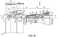
- Aircraft 10 comprises a fuselage 12, wings 14, cockpit controls 16, landing gear 18, and a propulsion system, such as gas turbine engines 20.
- Aircraft 10 may include a fuel and power transfer system 200.
- Gas turbine engine 20 may be a two-spool turbofan that generally incorporates a fan section 22, a compressor section 24, a combustor section 26 and a turbine section 28.
- fan section 22 can drive air along a bypass flow-path B while compressor section 24 can drive air through a core flow-path C for compression and communication into combustor section 26 then expansion through turbine section 28.
- Gas turbine engine 20 may incorporate a plurality of engine accessories such as, for example, components of power transfer system 200.
- turbofan gas turbine engine 20 Although depicted as a turbofan gas turbine engine 20 herein, it should be understood that the concepts described herein are not limited to use with turbofans as the teachings may be applied to other types of engines including turbojet engines, a low-bypass turbofans, a high bypass turbofans, reciprocating engines, or any other internal combustion engine known to those skilled in the art.
- Gas turbine engine 20 may generally comprise a low speed spool 30 and a high speed spool 32 mounted for rotation about an engine central longitudinal axis A-A' relative to an engine static structure 36 via one or more bearing systems 38 (shown as bearing system 38-1 and bearing system 38-2). It should be understood that various bearing systems 38 at various locations may alternatively or additionally be provided, including for example, bearing system 38, bearing system 38-1, and bearing system 38-2.
- Low speed spool 30 may generally comprise an inner shaft 40 that interconnects a fan 42, a low pressure (or first) compressor section 44 (also referred to a low pressure compressor) and a low pressure (or first) turbine section 46.
- Inner shaft 40 may be connected to fan 42 through a geared architecture 48 that can drive fan 42 at a lower speed than low speed spool 30.
- Geared architecture 48 may comprise a gear assembly 60 enclosed within a gear housing 62.
- Gear assembly 60 couples inner shaft 40 to a rotating fan structure.
- High speed spool 32 may comprise an outer shaft 50 that interconnects a high pressure compressor (“HPC") 52 (e.g., a second compressor section) and high pressure (or second) turbine section 54.
- HPC high pressure compressor
- a combustor 56 may be located between HPC 52 and high pressure turbine 54.
- a mid-turbine frame 57 of engine static structure 36 may be located generally between high pressure turbine 54 and low pressure turbine 46.
- Mid-turbine frame 57 may support one or more bearing systems 38 in turbine section 28.
- Inner shaft 40 and outer shaft 50 may be concentric and rotate via bearing systems 38 about the engine central longitudinal axis A-A', which is collinear with their longitudinal axes.
- a "high pressure" compressor or turbine experiences a higher pressure than a corresponding "low pressure” compressor or turbine.
- the core airflow C may be compressed by low pressure compressor 44 then HPC 52, mixed and burned with fuel in combustor 56, then expanded over high pressure turbine 54 and low pressure turbine 46.
- Mid-turbine frame 57 includes airfoils 59 which are in the core airflow path.
- Low pressure turbine 46, and high pressure turbine 54 rotationally drive the respective low speed spool 30 and high speed spool 32 in response to the expansion.
- Gas turbine engine 20 may be, for example, a high-bypass geared aircraft engine.
- the bypass ratio of gas turbine engine 20 may be greater than about six (6).
- the bypass ratio of gas turbine engine 20 may be greater than ten (10).
- Geared architecture 48 may be an epicyclic gear train, such as a star gear system (sun gear in meshing engagement with a plurality of star gears supported by a carrier and in meshing engagement with a ring gear) or other gear system.
- Geared architecture 48 may have a gear reduction ratio of greater than about 2.3 and low pressure turbine 46 may have a pressure ratio that is greater than about 5.
- the bypass ratio of gas turbine engine 20 is greater than about ten (10:1).
- the diameter of fan 42 may be significantly larger than that of the low pressure compressor 44, and the low pressure turbine 46 may have a pressure ratio that is greater than about (5:1). Low pressure turbine 46 pressure ratio may be measured prior to inlet of low pressure turbine 46 as related to the pressure at the outlet of low pressure turbine 46 prior to an exhaust nozzle. It should be understood, however, that the above parameters are exemplary of various embodiments of a suitable geared architecture engine and that the present disclosure contemplates other gas turbine engines including direct drive turbofans.
- the next generation of turbofan engines may be designed for higher efficiency which is associated with higher pressure ratios and higher temperatures in the HPC 52. These higher operating temperatures and pressure ratios may create operating environments that may cause thermal loads that are higher than the thermal loads encountered in conventional turbofan engines, which may shorten the operational life of current components.
- HPC 52 may comprise alternating rows of rotating rotors and stationary stators.
- Stators may have a cantilevered configuration or a shrouded configuration.
- a stator may comprise a stator vane, a casing support and a hub support.
- a stator vane may be supported along an outer diameter by a casing support and along an inner diameter by a hub support.
- a cantilevered stator may comprise a stator vane that is only retained and/or supported at the casing (e.g., along an outer diameter).
- rotors may be configured to compress and spin a fluid flow.
- Stators may be configured to receive and straighten the fluid flow.
- the fluid flow discharged from the trailing edge of stators may be straightened (e.g., the flow may be directed in a substantially parallel path to the centerline of the engine and/or HPC) to increase and/or improve the efficiency of the engine and, more specifically, to achieve maximum and/or near maximum compression and efficiency when the straightened air is compressed and spun by rotor 64.
- System 200 is shown integrated with the gas turbine engine 20 of aircraft 10 according to various embodiments.
- System 200 includes a controller 202 which may be integrated into computer systems onboard aircraft 10.
- controller 202 may be configured as a central network element or hub to access various systems, engines, and components of system 200.
- Controller 202 may comprise a network, computer-based system, and/or software components configured to provide an access point to various systems, engines, and components of system 200.
- controller 202 may comprise a processor.
- controller 202 may be implemented in a single processor.
- controller 202 may be implemented as and may include one or more processors and/or one or more tangible, non-transitory memories and be capable of implementing logic.
- Each processor can be a general purpose processor, a digital signal processor (DSP), an application specific integrated circuit (ASIC), a field programmable gate array (FPGA) or other programmable logic device, discrete gate or transistor logic, discrete hardware components, or any combination thereof.
- Controller 202 may comprise a processor configured to implement various logical operations in response to execution of instructions, for example, instructions stored on a non-transitory, tangible, computer-readable medium configured to communicate with controller 202. In this regard, controller 202 may be configured to control various components of system 200 via control signals 208.
- Non-transitory is to be understood to remove only propagating transitory signals per se and includes all standard computer-readable media that are not only propagating transitory signals per se.
- controller 202 may be in electronic communication with a pilot through a control interface 204 of cockpit controls 16, for example, a multifunction display, a switch panel, and/or the like which an operator can operate.
- the control interface 204 may enable the operator to interact with system 200 for example, to issue commands, display information such as, for example, warnings, or receive outputs.
- Control interface 204 may comprise any suitable combination of hardware, software, and/or database components.
- System 200 comprises one or more feedback elements to monitor and measure aircraft 10 and gas turbine engine 20 characteristics.
- controller 202 is in electronic communication with sensors 206 that may be coupled to or in direct electronic communication with aircraft systems such as, for example, propulsion systems, fuel systems (e.g., primary and secondary fuel systems), and/or the like.
- Controller 202 may be in electronic communication with the full suite of aircraft sensors and other data sources available within and without the aircraft 10.
- Sensors 206 may comprise a temperature sensor, a torque sensor, a speed sensor, a pressure sensor, a position sensor, an accelerometer, a voltmeter, an ammeter, a wattmeter, an optical sensor, or any other suitable measuring device known to those skilled in the art.
- Sensors 206 are configured to transmit measurements to controller 202, thereby providing sensor feedback about the measured system.
- the sensor feedback may be, for example, a speed signal, or may be position feedback, temperature feedback, pressure feedback or other data.
- System 200 includes a cryogenic fuel supply 210 which may be configured to store a fuel such as a cryogenic liquid fuel.
- the fuel may be one of molecular hydrogen, methane, ethane, propane, butane, natural gas and/or the like.
- the cryogenic fuel supply 210 is in fluid communication with a fuel pump 212 via supply line 214.
- the fuel pump 212 is configured to increase the pressure of the fuel (such as, for example, above a critical pressure of the fuel) and supply the fuel at an increased pressure to a multi-position valve 216.
- the fuel pump 212 is coupled to a gearbox 218 and receives operative power therefrom such as, for example, via a pump shaft.
- gearbox 218 may receive operative power from the gas turbine engine 20.
- gearbox 218 may be coupled to any of the spools (e.g., 30, 32) and/or shafts (e.g., 40, 50) of gas turbine engine 20 by a power transfer shaft 220.
- the power transfer shaft 220 may be coupled to the gearbox 218 through a power transfer clutch 222.
- the gearbox 218 may be selectively mechanically coupled to the gas turbine engine 20 and thereby configured to transmit to or receive power from the gas turbine engine 20.
- Gearbox 218 is mechanically coupled to a motor-generator 224 via an accessory clutch 228.
- the gearbox 218 is mechanically coupled to the motor-generator 224 via an accessory shaft 226 and the accessory clutch 228.
- Motor-generator 224 is selectively operable as a motor or as a generator.
- motor-generator 224 may be configured to provide operative power to the fuel pump 212 via the gearbox 218 by engaging the accessory clutch 228.
- motor-generator 224 may be configured to provide operative power to the gas turbine engine 20 via the gearbox 218 by engaging the accessory clutch 228 and the power transfer clutch 222.
- Motor-generator 224 may be coupled to an electrical load 230 such as, for example, an electrical power system of aircraft 10. When configured to operate as a generator, motor-generator 224 may supply electrical power to the electrical load 230 in response to receiving operative power from the gearbox 218. In various embodiments, the electrical load 230 may be disconnected from the motor-generator 224 by, for example, an electrical load disconnect relay 232.
- a fuel turbine 234 is operatively coupled to the fuel pump 212 and/or the gearbox 218 via a common shaft 237.
- the fuel turbine 234 may provide input to the gearbox 218 and subsequently drive the fuel pump 212 and motor-generator 224 via geared shafting configured to provide desired rotational speeds for each component.
- the fuel turbine 234 may be a variable pressure discharge turbine and includes a primary discharge port 236 (i.e., a first discharge port) and a secondary discharge port 238 (i.e., a second discharge port) in fluid communication with a combustion chamber of the gas turbine engine 20 (e.g., combustor 56).
- Each discharge port of the fuel turbine 234 is in fluid communication with a respective control valve configured to regulate and/or interrupt fluid communication with the combustion chamber.
- sensors 206 may include a first fuel pressure sensor 244 may be in fluid communication with the primary discharge port 236 and a second fuel pressure sensor 246 may be in fluid communication with the secondary discharge port 238.
- Multi-position valve 216 is in fluid communication with a primary heat exchanger 248.
- the multi-position valve 216 may be configured to send a portion of the fuel from fuel pump 212 through the primary heat exchanger 248.
- the primary heat exchanger 248 may extract heat from the gas turbine engine 20 and impart heat energy to the fuel.
- the primary heat exchanger 248 may be configured to vaporize and expand the fuel and deliver heated gaseous fuel to the inlet 250 of the fuel turbine 234.
- fuel serves as a working fluid for the fuel turbine 234 which may thereby extract energy from the working fluid to drive loads such as the fuel pump 212, gearbox 218, motor-generator 224, and power transfer shaft 220 and that these loads may be modulated (e.g., by commands from controller 202) via clutches 222 and 228.
- the heated gaseous fuel may be further expanded by the fuel turbine 234 and may be directed to the combustion chamber via the primary discharge port 236 and/or the secondary discharge port 238.
- multi-position valve 216 may be in fluid communication with an auxiliary heat exchanger 252 in fluid communication with the combustion chamber.
- the multi-position valve 216 may be selectively configurable to direct a portion or an entirety of the fuel pump 212 fuel output directly to any of the combustion chamber, the auxiliary heat exchanger 252, or the primary heat exchanger 248.
- the auxiliary heat exchanger 252 may be in fluid communication with the primary turbine discharge valve 240 and/or the secondary turbine discharge valve 242. In this regard, by selecting a position of the multi-position valve in response to a startup condition, the auxiliary heat exchanger 252 may be configured to preheat fuel from the fuel pump 212 to a gaseous state during the startup condition prior to introduction to the combustion chamber.
- the auxiliary heat exchanger 252 may be configured to reheat the expanded gaseous fuel from either of the primary discharge port 236 and/or the secondary discharge port 238 prior to introduction to the combustion chamber during the operating power condition.
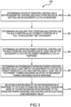
- Method 300 comprises determining a startup condition, controlling a motor-generator in response to the startup condition, controlling a multi-position valve in response to the startup condition, and controlling an accessory clutch in response to the startup condition (step 302).
- controller 202 determines a startup condition in response to an input from control interface 204 such as an engine start command.
- the controller 202 commands the accessory clutch 228 to engage and select a motor mode of the motor-generator 224.
- controller 202 provides operative force to the fuel pump 212 via gearbox 218.
- the controller 202 controls and/or configure the multi-position valve 216 to enable fluid communication between the fuel pump 212 and the combustion chamber but bypass the primary heat exchanger 248 in response to the startup condition.
- Method 300 includes controller 202 determining an auxiliary heat condition and controlling the multi-position valve 216 to direct a portion of a fuel to the auxiliary heat exchanger 252 (step 304).
- Method 300 includes determining an operating power condition, controlling the multi-position valve in response to the operating power condition, and controlling at least one of the accessory clutch or the power transfer clutch in response to the operating power condition (step 306).
- Method 300 includes determining an intermediate operating power condition, controlling at least one of the accessory clutch or the power transfer clutch in response to the intermediate operating power condition, and controlling at least one of the primary turbine discharge valve or the secondary turbine discharge valve in response to the intermediate operating power condition (step 308).
- the controller 202 may determine the intermediate operating condition based on a power setting of the turbine engine 20 such as, for example, a cruise power setting which may be entered via the control interface 204.
- the intermediate operating condition may be determined based on sensors 206 measurements such as, for example, measurements at a P3 (e.g., a combustor inlet pressure) station of the turbine engine 20 or a fuel pressure measurement.
- P3 e.g., a combustor inlet pressure
- an operating power condition may be determined where the measurements are relatively greater than that of the intermediate operating condition such as, for example, a full power setting which may be entered via the control interface 204.
- Method 300 includes selecting a motor mode of the motor generator in response to the startup condition, selecting a generator mode of the motor generator in response to the operating power condition, and controlling an electrical load disconnect relay in response to the operating power condition (step 310).
- controller 202 may determine an operating power condition or an intermediate operating power condition of gas turbine engine 20 such as, for example, based on sensor data from sensors 206 or in response to a power setting command from control interface 204.
- the controller 202 may receive a primary discharge port pressure from the first fuel pressure sensor 244 may a secondary discharge port pressure from the second fuel pressure sensor 246.
- the controller 202 may determine the operating power condition or the intermediate operating power condition based on the primary discharge port pressure and the secondary discharge port pressure.
- Controller 202 may control the multi-position valve 216 to enable fluid communication between the fuel pump 212, the primary heat exchanger 248, and the inlet 250 of the fuel turbine 234.
- the controller 202 may command accessory clutch 228 to engage and may command the power transfer clutch 222 to engage.
- the controller 202 may select a generator mode of the motor-generator 224 and may command the electrical load disconnect relay 232 to close and thereby enable electronic communication between the electrical load 230 and the motor-generator 224.
- the controller 202 may configure the fuel turbine 234 to transmit power to the gearbox 218 and thereby transfer power between the gas turbine engine 20 and the electrical load 230.
- Controller 202 may determine an intermediate operating power condition in response to an intermediate power setting from the control interface 204 or in response to sensor 206 data such as gas turbine engine 20 station temperatures, rotor speeds, internal pressures, inlet 250 temperature, the fuel turbine discharge port pressures and/or the like.
- the controller 202 may control or module each of the primary turbine discharge valve 240 and a secondary turbine discharge valve 242 in response to the intermediate power condition.
- the controller 202 may command the power transfer clutch to disengage.
- controller 202 may control the fuel turbine 234 discharge pressure to remain above the combustion chamber operating pressure and thereby tend to inhibit back driving of the fuel turbine 234 by the gas turbine engine 20.
- references to "various embodiments,” “one embodiment,” “an embodiment,” “an example embodiment,” etc. indicate that the embodiment described may include a particular feature, structure, or characteristic, but every embodiment may not necessarily include the particular feature, structure, or characteristic. Moreover, such phrases are not necessarily referring to the same embodiment. Further, when a particular feature, structure, or characteristic is described in connection with an embodiment, it is submitted that it is within the knowledge of one skilled in the art to affect such feature, structure, or characteristic in connection with other embodiments whether or not explicitly described. After reading the description, it will be apparent to one skilled in the relevant art(s) how to implement the disclosure in alternative embodiments.
- the terms "comprises,” “comprising,” or any other variation thereof, are intended to cover a non-exclusive inclusion, such that a process, method, article, or apparatus that comprises a list of elements does not include only those elements but may include other elements not expressly listed or inherent to such process, method, article, or apparatus.
Landscapes
- Engineering & Computer Science (AREA)
- Chemical & Material Sciences (AREA)
- Combustion & Propulsion (AREA)
- Mechanical Engineering (AREA)
- General Engineering & Computer Science (AREA)
- Engine Equipment That Uses Special Cycles (AREA)
Claims (7)
- Brennstoff-Energieübertragungssystem (200) für ein Triebwerk (20), umfassend:ein Lager mit kryogenem Brennstoff (210);eine Brennstoffpumpe (212) in Fluidverbindung mit dem Lager mit kryogenem Brennstoff;ein Mehrpositionsventil (216) in Fluidverbindung mit der Brennstoffpumpe und zur Fluidverbindung mit einer Brennkammer des Triebwerks konfiguriert;eine Brennstoffturbine (234), die über eine gemeinsame Welle (237) mit der Brennstoffpumpe wirkgekoppelt ist und eine erste Auslassöffnung (236) aufweist, die zur Fluidverbindung mit der Brennkammer konfiguriert ist;einen primären Wärmetauscher (248) in Fluidverbindung zwischen dem Mehrpositionsventil und der Brennstoffturbine;ein Getriebe (218), das mit der Brennstoffturbine und der Brennstoffpumpe wirkgekoppelt ist und zum Übertragen von Energie von der Brennstoffturbine an das Triebwerk konfiguriert ist;einen Triebwerk-Generator (224), der mit dem Getriebe wirkgekoppelt ist und selektiv zum Betreiben als Triebwerk oder als Generator konfigurierbar ist, wobei der Triebwerk-Generator über eine Zusatzkupplung (228) mit dem Getriebe gekoppelt ist und das Getriebe zum Übertragen von Energie von der Brennstoffturbine über eine Energieübertragungskupplung (222) zu dem Triebwerk konfiguriert ist;eine Steuervorrichtung (202);einen Sensor (206) in Kommunikation mit der Steuervorrichtung und zum Bereitstellen von Sensorrückmeldungen konfiguriert;einen physischen, nichtflüchtigen Speicher, der zum Kommunizieren mit der Steuervorrichtung konfiguriert ist, wobei in dem physischen, nichtflüchtigen Speicher Anweisungen gespeichert sind, die als Reaktion auf eine Ausführung durch die Steuervorrichtung die Steuervorrichtung zum Durchführen von Operationen veranlassen, umfassend:Bestimmen eines Startzustands durch die Steuervorrichtung als Reaktion auf einen Triebwerkstartbefehl;Steuern des Triebwerk-Generators durch die Steuervorrichtung als Reaktion auf den Startzustand;Steuern des Mehrpositionsventils durch die Steuervorrichtung zum Ermöglichen einer Fluidverbindung zwischen der Brennstoffpumpe und der Brennkammer, jedoch unter Umgehen des primären Wärmetauschers, als Reaktion auf den Startzustand; undSteuern der Zusatzkupplung zum Einrücken und Wählen eines Triebwerkmodus des Triebwerk-Generators durch die Steuervorrichtung als Reaktion auf den Startzustand, wobei die Steuervorrichtung über das Getriebe eine Wirkkraft an der Brennstoffpumpe bereitstellt, wobei das System ferner Folgendes umfasst:ein erstes Turbinenauslassventil (240), das zum Steuern durch die Steuervorrichtung und zur Fluidverbindung zwischen der Brennkammer und der ersten Auslassöffnung konfiguriert ist; undein zweites Turbinenauslassventil (242), das zum Steuern durch die Steuervorrichtung und zur Fluidverbindung zwischen der Brennkammer und einer zweiten Auslassöffnung (238) der Brennstoffturbine konfiguriert ist,wobei jedes des ersten Turbinenauslassventils und des zweiten Turbinenauslassventils zum Unterbrechen der Fluidverbindung mit der Brennkammer konfiguriert ist.
- System (200) nach Anspruch 1, ferner umfassend einen Hilfswärmetauscher (252), der zur Fluidverbindung zwischen dem Mehrpositionsventil (216) und der Brennkammer konfiguriert ist.
- System (200) nach Anspruch 1 oder 2, wobei die Operationen ferner Folgendes umfassen:Bestimmen eines Hilfswärmezustands durch die Steuervorrichtung; undSteuern des Mehrpositionsventils (216) durch die Steuervorrichtung (202) zum Leiten eines Teils des Lagers mit kryogenem Brennstoff (210) zu einem Hilfswärmetauscher (252) in Fluidverbindung mit der Brennkammer als Reaktion auf den Hilfswärmezustand.
- System (200) nach Anspruch 1, 2 oder 3, wobei die Operationen ferner Folgendes umfassen:Bestimmen eines Betriebsenergiezustands durch die Steuervorrichtung (202);Steuern des Mehrpositionsventils (216) durch die Steuervorrichtung als Reaktion auf den Betriebsenergiezustand zum Ermöglichen von Fluidverbindung zwischen der Brennstoffpumpe (212), dem primären Wärmetauscher (248) und einem Einlass (250) der Brennstoffturbine (234); undSteuern des Einrückens von mindestens einer von der Zusatzkupplung (228) oder der Energieübertragungskupplung (222) durch die Steuervorrichtung als Reaktion auf den Betriebsenergiezustand.
- System (200) nach einem der vorhergehenden Ansprüche, wobei die Operationen ferner Folgendes umfassen:Bestimmen eines Zwischenbetriebsenergiezustands durch die Steuervorrichtung (202);Steuern des Einrückens von mindestens einer von der Zusatzkupplung (228) oder der Energieübertragungskupplung (222) durch die Steuervorrichtung als Reaktion auf den Zwischenbetriebsenergiezustand; undSteuern von mindestens einem von dem ersten Turbinenauslassventil (240) oder dem zweiten Turbinenauslassventil (242) durch die Steuervorrichtung als Reaktion auf den Zwischenbetriebsenergiezustand.
- System (200) nach Anspruch 5, wobei der Sensor (206) einen ersten Brennstoffdrucksensor (244) in Fluidverbindung mit der ersten Auslassöffnung (236) und einen zweiten Brennstoffdrucksensor (246) in Fluidverbindung mit der zweiten Auslassöffnung (238) umfasst, wobei die Operationen ferner Folgendes umfassen:Empfangen eines Drucks der primären Auslassöffnung und eines Drucks der sekundären Auslassöffnung durch die Steuervorrichtung; undBestimmen des Betriebsenergiezustands oder des Zwischenbetriebsenergiezustands durch die Steuervorrichtung basierend auf dem Druck der primären Auslassöffnung und dem Druck der sekundären Auslassöffnung.
- System (200) nach einem der vorhergehenden Ansprüche, wobei die Operationen ferner Folgendes umfassen:Wählen eines Triebwerkmodus des Triebwerk-Generators (224) durch die Steuervorrichtung (202) als Reaktion auf den Startzustand;Wählen eines Generatormodus des Triebwerk-Generators durch die Steuervorrichtung als Reaktion auf den Betriebsenergiezustand; undSteuern eines Trennrelais für elektrische Last (232) durch die Steuervorrichtung als Reaktion auf den Betriebsenergiezustand.
Priority Applications (1)
| Application Number | Priority Date | Filing Date | Title |
|---|---|---|---|
| EP24166994.4A EP4368826A3 (de) | 2020-01-06 | 2021-01-04 | Systeme und verfahren zur leistungsübertragung in kryogenen kraftstoffanwendungen |
Applications Claiming Priority (1)
| Application Number | Priority Date | Filing Date | Title |
|---|---|---|---|
| US16/734,925 US11434823B2 (en) | 2020-01-06 | 2020-01-06 | Systems and methods for power transfer in cryogenic fuel applications |
Related Child Applications (2)
| Application Number | Title | Priority Date | Filing Date |
|---|---|---|---|
| EP24166994.4A Division EP4368826A3 (de) | 2020-01-06 | 2021-01-04 | Systeme und verfahren zur leistungsübertragung in kryogenen kraftstoffanwendungen |
| EP24166994.4A Division-Into EP4368826A3 (de) | 2020-01-06 | 2021-01-04 | Systeme und verfahren zur leistungsübertragung in kryogenen kraftstoffanwendungen |
Publications (3)
| Publication Number | Publication Date |
|---|---|
| EP3855002A2 EP3855002A2 (de) | 2021-07-28 |
| EP3855002A3 EP3855002A3 (de) | 2021-10-06 |
| EP3855002B1 true EP3855002B1 (de) | 2024-09-25 |
Family
ID=74095758
Family Applications (2)
| Application Number | Title | Priority Date | Filing Date |
|---|---|---|---|
| EP21150109.3A Active EP3855002B1 (de) | 2020-01-06 | 2021-01-04 | Systeme und verfahren zur energieübertragung in kryogenen brennstoffanwendungen |
| EP24166994.4A Pending EP4368826A3 (de) | 2020-01-06 | 2021-01-04 | Systeme und verfahren zur leistungsübertragung in kryogenen kraftstoffanwendungen |
Family Applications After (1)
| Application Number | Title | Priority Date | Filing Date |
|---|---|---|---|
| EP24166994.4A Pending EP4368826A3 (de) | 2020-01-06 | 2021-01-04 | Systeme und verfahren zur leistungsübertragung in kryogenen kraftstoffanwendungen |
Country Status (2)
| Country | Link |
|---|---|
| US (2) | US11434823B2 (de) |
| EP (2) | EP3855002B1 (de) |
Families Citing this family (20)
| Publication number | Priority date | Publication date | Assignee | Title |
|---|---|---|---|---|
| US11745891B2 (en) * | 2020-04-14 | 2023-09-05 | Raytheon Technologies Corporation | Aircraft fuel system with electrochemical hydrogen compressor |
| US20220364513A1 (en) * | 2021-05-14 | 2022-11-17 | Raytheon Technologies Corporation | Turbine engines having hydrogen fuel systems |
| EP4367373A2 (de) * | 2021-07-09 | 2024-05-15 | RTX Corporation | Turbinenmotoren mit wasserstoffbrennstoffsystemen |
| US11761381B2 (en) * | 2021-08-14 | 2023-09-19 | Pratt & Whitney Canada Corp. | Gas turbine engine comprising liquid hydrogen evaporators and heaters |
| US11754021B2 (en) * | 2021-08-20 | 2023-09-12 | Raytheon Technologies Corporation | Propulsion systems for aircraft |
| US11952946B2 (en) | 2021-10-15 | 2024-04-09 | Rtx Corporation | Turbine engine with preheat of cryogenic fuel via intermediate fluid |
| GB202203007D0 (en) * | 2022-03-04 | 2022-04-20 | Rolls Royce Plc | Combined cycles |
| GB202204073D0 (en) | 2022-03-23 | 2022-05-04 | Rolls Royce Plc | Fuel system |
| GB202207929D0 (en) | 2022-05-30 | 2022-07-13 | Rolls Royce Plc | Hydrogen-fuelled gas turbine engine with fuel-to-air turbocharger |
| US11987377B2 (en) | 2022-07-08 | 2024-05-21 | Rtx Corporation | Turbo expanders for turbine engines having hydrogen fuel systems |
| US12103699B2 (en) | 2022-07-08 | 2024-10-01 | Rtx Corporation | Hybrid electric power for turbine engines having hydrogen fuel systems |
| US20240018908A1 (en) * | 2022-07-14 | 2024-01-18 | Pratt & Whitney Canada Corp. | Aircraft power plant with hydrogen turbo-expander |
| US12092036B2 (en) * | 2022-12-21 | 2024-09-17 | Ge Infrastructure Technology Llc | Alternative fuel fast start systems for gas turbine engines |
| EP4491857A1 (de) * | 2023-07-10 | 2025-01-15 | Rolls-Royce plc | Wasserstoffbetriebener gasturbinenmotor |
| GB202403178D0 (en) * | 2024-03-05 | 2024-04-17 | Rolls Royce Plc | Hydrogen fuelled gas turbine engine |
| US20250297574A1 (en) * | 2024-03-22 | 2025-09-25 | Hamilton Sundstrand Corporation | Fuel system with fuel cooled electric generation and fuel oil cooler elimination |
| US20250341190A1 (en) * | 2024-05-03 | 2025-11-06 | Pratt & Whitney Canada Corp. | Partial-admission turbine assembly for an aircraft and method for controlling same |
| US20250369391A1 (en) * | 2024-05-31 | 2025-12-04 | Ge Avio S.R.L. | Cryogenic fuel distribution systems including heat exchangers and related methods |
| US12460580B1 (en) * | 2024-12-13 | 2025-11-04 | Pratt & Whitney Canada Corp. | Heat management system and method for hydrogen-fueled engine |
| US12529338B1 (en) * | 2024-12-13 | 2026-01-20 | General Electric Company | Heat source for hydrogen fuel supply system |
Family Cites Families (19)
| Publication number | Priority date | Publication date | Assignee | Title |
|---|---|---|---|---|
| US2839005A (en) * | 1953-10-14 | 1958-06-17 | Herbert E Means | Turbine driven pump |
| DE2413507A1 (de) | 1974-03-20 | 1975-10-02 | Motoren Turbinen Union | Gasturbine fuer kryogenen kraftstoff |
| US5161365A (en) | 1990-12-05 | 1992-11-10 | Allied-Signal Inc. | Endothermic fuel power generator and method |
| US6628006B2 (en) * | 2001-05-03 | 2003-09-30 | Ford Motor Company | System and method for recovering potential energy of a hydrogen gas fuel supply for use in a vehicle |
| US7565805B2 (en) * | 2005-11-22 | 2009-07-28 | General Electric Company | Method for operating gas turbine engine systems |
| US20070175222A1 (en) * | 2006-01-31 | 2007-08-02 | United Technologies Corporation | Multipurpose gas generator ramjet/scramjet cold start system |
| US7788898B2 (en) * | 2006-12-06 | 2010-09-07 | General Electric Company | Variable coupling of turbofan engine spools via open differential gear set or simple planetary gear set for improved power extraction and engine operability, with torque coupling for added flexibility |
| RU2353787C1 (ru) * | 2007-09-06 | 2009-04-27 | Открытое акционерное общество "Российские железные дороги" (ОАО "РЖД") | Газотурбинная установка |
| US8684304B2 (en) | 2010-11-16 | 2014-04-01 | Rolls-Royce Corporation | Aircraft, propulsion system, and system for taxiing an aircraft |
| US8727270B2 (en) | 2010-11-16 | 2014-05-20 | Rolls-Royce Corporation | Aircraft, propulsion system, and system for taxiing an aircraft |
| FR2983248B1 (fr) * | 2011-11-29 | 2015-04-03 | Turbomeca | Turbomachine comportant une pompe d'alimentation en carburant a activation electrique et procede d'alimentation en carburant d'une turbomachine |
| BR112015023299A2 (pt) | 2013-03-15 | 2017-07-18 | Gen Electric | método de uso de combustível criogênico e sistema de vaporização de combustível |
| US9908635B2 (en) | 2013-03-15 | 2018-03-06 | Rolls-Royce North American Technologies Inc. | Aircraft system |
| US10125692B2 (en) * | 2014-08-22 | 2018-11-13 | Rolls-Royce Corporation | Gas turbine engine system having a disengageable electric machine |
| GB2531775B (en) * | 2014-10-30 | 2018-05-09 | Rolls Royce Plc | A gas turbine using cryogenic fuel passed through a fuel turbine |
| US9932850B2 (en) * | 2015-02-03 | 2018-04-03 | General Electric Company | Correction system and method for gas turbine proportional droop governor |
| US10273883B2 (en) * | 2016-02-26 | 2019-04-30 | The Boeing Company | Engine accessory drives systems and methods |
| JP7471776B2 (ja) * | 2019-02-18 | 2024-04-22 | 三菱重工業株式会社 | ジェットエンジン |
| GB2584094B (en) * | 2019-05-20 | 2022-01-26 | Rolls Royce Plc | Engine |
-
2020
- 2020-01-06 US US16/734,925 patent/US11434823B2/en active Active
-
2021
- 2021-01-04 EP EP21150109.3A patent/EP3855002B1/de active Active
- 2021-01-04 EP EP24166994.4A patent/EP4368826A3/de active Pending
-
2022
- 2022-07-29 US US17/877,566 patent/US12345204B2/en active Active
Also Published As
| Publication number | Publication date |
|---|---|
| US11434823B2 (en) | 2022-09-06 |
| US20210207537A1 (en) | 2021-07-08 |
| EP3855002A3 (de) | 2021-10-06 |
| US12345204B2 (en) | 2025-07-01 |
| EP3855002A2 (de) | 2021-07-28 |
| US20230145878A1 (en) | 2023-05-11 |
| EP4368826A3 (de) | 2024-07-31 |
| EP4368826A2 (de) | 2024-05-15 |
Similar Documents
| Publication | Publication Date | Title |
|---|---|---|
| EP3855002B1 (de) | Systeme und verfahren zur energieübertragung in kryogenen brennstoffanwendungen | |
| EP3845747B1 (de) | Systeme und verfahren zur brennstoffzellen-hilfsenergie in sekundären brennstoffanwendungen | |
| EP3693578B1 (de) | Hybrid-elektrisches getriebe mit doppelspulenleistungsextraktion | |
| US11686253B2 (en) | Through-flow gas turbine engine with electric motor and electric generator | |
| US11891967B2 (en) | Turbofan comprising a power supply device to drive the compressor | |
| US20180045119A1 (en) | Geared turbofan with low spool power extraction | |
| US12123344B2 (en) | Engine and secondary power unit integrated operation | |
| EP4177449B1 (de) | Hilfsgetriebe mit überlagerungsgetriebe | |
| US12497918B2 (en) | Turbine engine with inverse Brayton cycle | |
| JP2024540969A (ja) | ハイブリッド推進システム | |
| EP4407159B1 (de) | Systeme und verfahren zur leistungsregelung mit doppeltwellenkonfiguration | |
| US12571438B2 (en) | Turboshaft engine clutch configuration | |
| US12359623B1 (en) | Hydrogen turboexpander for use in an aviation propulsion system | |
| EP4636234A1 (de) | Überwachung der brennstoffphase in einem flugzeugtriebwerk-kraftstoffsystem | |
| CA3270160A1 (en) | Hydrogen turboexpander for use in an aviation propulsion system | |
| EP3628849A1 (de) | Schubausgleichssteuerung mit differentieller leistungsaufnahme |
Legal Events
| Date | Code | Title | Description |
|---|---|---|---|
| PUAI | Public reference made under article 153(3) epc to a published international application that has entered the european phase |
Free format text: ORIGINAL CODE: 0009012 |
|
| STAA | Information on the status of an ep patent application or granted ep patent |
Free format text: STATUS: THE APPLICATION HAS BEEN PUBLISHED |
|
| AK | Designated contracting states |
Kind code of ref document: A2 Designated state(s): AL AT BE BG CH CY CZ DE DK EE ES FI FR GB GR HR HU IE IS IT LI LT LU LV MC MK MT NL NO PL PT RO RS SE SI SK SM TR |
|
| PUAL | Search report despatched |
Free format text: ORIGINAL CODE: 0009013 |
|
| AK | Designated contracting states |
Kind code of ref document: A3 Designated state(s): AL AT BE BG CH CY CZ DE DK EE ES FI FR GB GR HR HU IE IS IT LI LT LU LV MC MK MT NL NO PL PT RO RS SE SI SK SM TR |
|
| RIC1 | Information provided on ipc code assigned before grant |
Ipc: F02C 9/40 20060101ALI20210901BHEP Ipc: F02C 7/26 20060101ALI20210901BHEP Ipc: F02C 7/22 20060101ALI20210901BHEP Ipc: F02C 3/20 20060101AFI20210901BHEP |
|
| STAA | Information on the status of an ep patent application or granted ep patent |
Free format text: STATUS: REQUEST FOR EXAMINATION WAS MADE |
|
| 17P | Request for examination filed |
Effective date: 20220406 |
|
| RBV | Designated contracting states (corrected) |
Designated state(s): AL AT BE BG CH CY CZ DE DK EE ES FI FR GB GR HR HU IE IS IT LI LT LU LV MC MK MT NL NO PL PT RO RS SE SI SK SM TR |
|
| RAP3 | Party data changed (applicant data changed or rights of an application transferred) |
Owner name: RTX CORPORATION |
|
| GRAP | Despatch of communication of intention to grant a patent |
Free format text: ORIGINAL CODE: EPIDOSNIGR1 |
|
| STAA | Information on the status of an ep patent application or granted ep patent |
Free format text: STATUS: GRANT OF PATENT IS INTENDED |
|
| INTG | Intention to grant announced |
Effective date: 20231201 |
|
| GRAJ | Information related to disapproval of communication of intention to grant by the applicant or resumption of examination proceedings by the epo deleted |
Free format text: ORIGINAL CODE: EPIDOSDIGR1 |
|
| STAA | Information on the status of an ep patent application or granted ep patent |
Free format text: STATUS: REQUEST FOR EXAMINATION WAS MADE |
|
| GRAP | Despatch of communication of intention to grant a patent |
Free format text: ORIGINAL CODE: EPIDOSNIGR1 |
|
| STAA | Information on the status of an ep patent application or granted ep patent |
Free format text: STATUS: GRANT OF PATENT IS INTENDED |
|
| INTC | Intention to grant announced (deleted) | ||
| INTG | Intention to grant announced |
Effective date: 20240430 |
|
| GRAS | Grant fee paid |
Free format text: ORIGINAL CODE: EPIDOSNIGR3 |
|
| GRAA | (expected) grant |
Free format text: ORIGINAL CODE: 0009210 |
|
| STAA | Information on the status of an ep patent application or granted ep patent |
Free format text: STATUS: THE PATENT HAS BEEN GRANTED |
|
| AK | Designated contracting states |
Kind code of ref document: B1 Designated state(s): AL AT BE BG CH CY CZ DE DK EE ES FI FR GB GR HR HU IE IS IT LI LT LU LV MC MK MT NL NO PL PT RO RS SE SI SK SM TR |
|
| REG | Reference to a national code |
Ref country code: GB Ref legal event code: FG4D |
|
| REG | Reference to a national code |
Ref country code: CH Ref legal event code: EP |
|
| REG | Reference to a national code |
Ref country code: DE Ref legal event code: R096 Ref document number: 602021019135 Country of ref document: DE |
|
| REG | Reference to a national code |
Ref country code: IE Ref legal event code: FG4D |
|
| REG | Reference to a national code |
Ref country code: LT Ref legal event code: MG9D |
|
| PG25 | Lapsed in a contracting state [announced via postgrant information from national office to epo] |
Ref country code: NO Free format text: LAPSE BECAUSE OF FAILURE TO SUBMIT A TRANSLATION OF THE DESCRIPTION OR TO PAY THE FEE WITHIN THE PRESCRIBED TIME-LIMIT Effective date: 20241225 |
|
| PG25 | Lapsed in a contracting state [announced via postgrant information from national office to epo] |
Ref country code: GR Free format text: LAPSE BECAUSE OF FAILURE TO SUBMIT A TRANSLATION OF THE DESCRIPTION OR TO PAY THE FEE WITHIN THE PRESCRIBED TIME-LIMIT Effective date: 20241226 Ref country code: FI Free format text: LAPSE BECAUSE OF FAILURE TO SUBMIT A TRANSLATION OF THE DESCRIPTION OR TO PAY THE FEE WITHIN THE PRESCRIBED TIME-LIMIT Effective date: 20240925 |
|
| PG25 | Lapsed in a contracting state [announced via postgrant information from national office to epo] |
Ref country code: BG Free format text: LAPSE BECAUSE OF FAILURE TO SUBMIT A TRANSLATION OF THE DESCRIPTION OR TO PAY THE FEE WITHIN THE PRESCRIBED TIME-LIMIT Effective date: 20240925 |
|
| PG25 | Lapsed in a contracting state [announced via postgrant information from national office to epo] |
Ref country code: LV Free format text: LAPSE BECAUSE OF FAILURE TO SUBMIT A TRANSLATION OF THE DESCRIPTION OR TO PAY THE FEE WITHIN THE PRESCRIBED TIME-LIMIT Effective date: 20240925 |
|
| PG25 | Lapsed in a contracting state [announced via postgrant information from national office to epo] |
Ref country code: RS Free format text: LAPSE BECAUSE OF FAILURE TO SUBMIT A TRANSLATION OF THE DESCRIPTION OR TO PAY THE FEE WITHIN THE PRESCRIBED TIME-LIMIT Effective date: 20241225 |
|
| REG | Reference to a national code |
Ref country code: NL Ref legal event code: MP Effective date: 20240925 |
|
| PG25 | Lapsed in a contracting state [announced via postgrant information from national office to epo] |
Ref country code: RS Free format text: LAPSE BECAUSE OF FAILURE TO SUBMIT A TRANSLATION OF THE DESCRIPTION OR TO PAY THE FEE WITHIN THE PRESCRIBED TIME-LIMIT Effective date: 20241225 Ref country code: NO Free format text: LAPSE BECAUSE OF FAILURE TO SUBMIT A TRANSLATION OF THE DESCRIPTION OR TO PAY THE FEE WITHIN THE PRESCRIBED TIME-LIMIT Effective date: 20241225 Ref country code: LV Free format text: LAPSE BECAUSE OF FAILURE TO SUBMIT A TRANSLATION OF THE DESCRIPTION OR TO PAY THE FEE WITHIN THE PRESCRIBED TIME-LIMIT Effective date: 20240925 Ref country code: GR Free format text: LAPSE BECAUSE OF FAILURE TO SUBMIT A TRANSLATION OF THE DESCRIPTION OR TO PAY THE FEE WITHIN THE PRESCRIBED TIME-LIMIT Effective date: 20241226 Ref country code: FI Free format text: LAPSE BECAUSE OF FAILURE TO SUBMIT A TRANSLATION OF THE DESCRIPTION OR TO PAY THE FEE WITHIN THE PRESCRIBED TIME-LIMIT Effective date: 20240925 Ref country code: BG Free format text: LAPSE BECAUSE OF FAILURE TO SUBMIT A TRANSLATION OF THE DESCRIPTION OR TO PAY THE FEE WITHIN THE PRESCRIBED TIME-LIMIT Effective date: 20240925 |
|
| REG | Reference to a national code |
Ref country code: AT Ref legal event code: MK05 Ref document number: 1726804 Country of ref document: AT Kind code of ref document: T Effective date: 20240925 |
|
| PG25 | Lapsed in a contracting state [announced via postgrant information from national office to epo] |
Ref country code: NL Free format text: LAPSE BECAUSE OF FAILURE TO SUBMIT A TRANSLATION OF THE DESCRIPTION OR TO PAY THE FEE WITHIN THE PRESCRIBED TIME-LIMIT Effective date: 20240925 |
|
| PG25 | Lapsed in a contracting state [announced via postgrant information from national office to epo] |
Ref country code: IS Free format text: LAPSE BECAUSE OF FAILURE TO SUBMIT A TRANSLATION OF THE DESCRIPTION OR TO PAY THE FEE WITHIN THE PRESCRIBED TIME-LIMIT Effective date: 20250125 Ref country code: PT Free format text: LAPSE BECAUSE OF FAILURE TO SUBMIT A TRANSLATION OF THE DESCRIPTION OR TO PAY THE FEE WITHIN THE PRESCRIBED TIME-LIMIT Effective date: 20250127 |
|
| PG25 | Lapsed in a contracting state [announced via postgrant information from national office to epo] |
Ref country code: RO Free format text: LAPSE BECAUSE OF FAILURE TO SUBMIT A TRANSLATION OF THE DESCRIPTION OR TO PAY THE FEE WITHIN THE PRESCRIBED TIME-LIMIT Effective date: 20240925 Ref country code: SM Free format text: LAPSE BECAUSE OF FAILURE TO SUBMIT A TRANSLATION OF THE DESCRIPTION OR TO PAY THE FEE WITHIN THE PRESCRIBED TIME-LIMIT Effective date: 20240925 |
|
| PG25 | Lapsed in a contracting state [announced via postgrant information from national office to epo] |
Ref country code: ES Free format text: LAPSE BECAUSE OF FAILURE TO SUBMIT A TRANSLATION OF THE DESCRIPTION OR TO PAY THE FEE WITHIN THE PRESCRIBED TIME-LIMIT Effective date: 20240925 |
|
| PG25 | Lapsed in a contracting state [announced via postgrant information from national office to epo] |
Ref country code: EE Free format text: LAPSE BECAUSE OF FAILURE TO SUBMIT A TRANSLATION OF THE DESCRIPTION OR TO PAY THE FEE WITHIN THE PRESCRIBED TIME-LIMIT Effective date: 20240925 Ref country code: AT Free format text: LAPSE BECAUSE OF FAILURE TO SUBMIT A TRANSLATION OF THE DESCRIPTION OR TO PAY THE FEE WITHIN THE PRESCRIBED TIME-LIMIT Effective date: 20240925 |
|
| PG25 | Lapsed in a contracting state [announced via postgrant information from national office to epo] |
Ref country code: CZ Free format text: LAPSE BECAUSE OF FAILURE TO SUBMIT A TRANSLATION OF THE DESCRIPTION OR TO PAY THE FEE WITHIN THE PRESCRIBED TIME-LIMIT Effective date: 20240925 Ref country code: PL Free format text: LAPSE BECAUSE OF FAILURE TO SUBMIT A TRANSLATION OF THE DESCRIPTION OR TO PAY THE FEE WITHIN THE PRESCRIBED TIME-LIMIT Effective date: 20240925 |
|
| PG25 | Lapsed in a contracting state [announced via postgrant information from national office to epo] |
Ref country code: IT Free format text: LAPSE BECAUSE OF FAILURE TO SUBMIT A TRANSLATION OF THE DESCRIPTION OR TO PAY THE FEE WITHIN THE PRESCRIBED TIME-LIMIT Effective date: 20240925 Ref country code: SK Free format text: LAPSE BECAUSE OF FAILURE TO SUBMIT A TRANSLATION OF THE DESCRIPTION OR TO PAY THE FEE WITHIN THE PRESCRIBED TIME-LIMIT Effective date: 20240925 |
|
| REG | Reference to a national code |
Ref country code: DE Ref legal event code: R097 Ref document number: 602021019135 Country of ref document: DE |
|
| PG25 | Lapsed in a contracting state [announced via postgrant information from national office to epo] |
Ref country code: DK Free format text: LAPSE BECAUSE OF FAILURE TO SUBMIT A TRANSLATION OF THE DESCRIPTION OR TO PAY THE FEE WITHIN THE PRESCRIBED TIME-LIMIT Effective date: 20240925 |
|
| PLBE | No opposition filed within time limit |
Free format text: ORIGINAL CODE: 0009261 |
|
| STAA | Information on the status of an ep patent application or granted ep patent |
Free format text: STATUS: NO OPPOSITION FILED WITHIN TIME LIMIT |
|
| REG | Reference to a national code |
Ref country code: CH Ref legal event code: PL |
|
| 26N | No opposition filed |
Effective date: 20250626 |
|
| PG25 | Lapsed in a contracting state [announced via postgrant information from national office to epo] |
Ref country code: SE Free format text: LAPSE BECAUSE OF FAILURE TO SUBMIT A TRANSLATION OF THE DESCRIPTION OR TO PAY THE FEE WITHIN THE PRESCRIBED TIME-LIMIT Effective date: 20240925 |
|
| PG25 | Lapsed in a contracting state [announced via postgrant information from national office to epo] |
Ref country code: LU Free format text: LAPSE BECAUSE OF NON-PAYMENT OF DUE FEES Effective date: 20250104 Ref country code: MC Free format text: LAPSE BECAUSE OF FAILURE TO SUBMIT A TRANSLATION OF THE DESCRIPTION OR TO PAY THE FEE WITHIN THE PRESCRIBED TIME-LIMIT Effective date: 20240925 |
|
| PG25 | Lapsed in a contracting state [announced via postgrant information from national office to epo] |
Ref country code: BE Free format text: LAPSE BECAUSE OF NON-PAYMENT OF DUE FEES Effective date: 20250131 |
|
| PG25 | Lapsed in a contracting state [announced via postgrant information from national office to epo] |
Ref country code: CH Free format text: LAPSE BECAUSE OF NON-PAYMENT OF DUE FEES Effective date: 20250131 |
|
| REG | Reference to a national code |
Ref country code: BE Ref legal event code: MM Effective date: 20250131 |
|
| PGFP | Annual fee paid to national office [announced via postgrant information from national office to epo] |
Ref country code: GB Payment date: 20251220 Year of fee payment: 6 |
|
| PG25 | Lapsed in a contracting state [announced via postgrant information from national office to epo] |
Ref country code: HR Free format text: LAPSE BECAUSE OF FAILURE TO SUBMIT A TRANSLATION OF THE DESCRIPTION OR TO PAY THE FEE WITHIN THE PRESCRIBED TIME-LIMIT Effective date: 20240925 |
|
| PGFP | Annual fee paid to national office [announced via postgrant information from national office to epo] |
Ref country code: FR Payment date: 20251217 Year of fee payment: 6 |
|
| PG25 | Lapsed in a contracting state [announced via postgrant information from national office to epo] |
Ref country code: IE Free format text: LAPSE BECAUSE OF NON-PAYMENT OF DUE FEES Effective date: 20250104 |
|
| PGFP | Annual fee paid to national office [announced via postgrant information from national office to epo] |
Ref country code: DE Payment date: 20251217 Year of fee payment: 6 |