EP3845747B1 - Systeme und verfahren zur brennstoffzellen-hilfsenergie in sekundären brennstoffanwendungen - Google Patents
Systeme und verfahren zur brennstoffzellen-hilfsenergie in sekundären brennstoffanwendungen Download PDFInfo
- Publication number
- EP3845747B1 EP3845747B1 EP20217693.9A EP20217693A EP3845747B1 EP 3845747 B1 EP3845747 B1 EP 3845747B1 EP 20217693 A EP20217693 A EP 20217693A EP 3845747 B1 EP3845747 B1 EP 3845747B1
- Authority
- EP
- European Patent Office
- Prior art keywords
- valve
- controller
- response
- fluid communication
- engine
- Prior art date
- Legal status (The legal status is an assumption and is not a legal conclusion. Google has not performed a legal analysis and makes no representation as to the accuracy of the status listed.)
- Active
Links
Images

Classifications
-
- F—MECHANICAL ENGINEERING; LIGHTING; HEATING; WEAPONS; BLASTING
- F02—COMBUSTION ENGINES; HOT-GAS OR COMBUSTION-PRODUCT ENGINE PLANTS
- F02C—GAS-TURBINE PLANTS; AIR INTAKES FOR JET-PROPULSION PLANTS; CONTROLLING FUEL SUPPLY IN AIR-BREATHING JET-PROPULSION PLANTS
- F02C3/00—Gas-turbine plants characterised by the use of combustion products as the working fluid
- F02C3/20—Gas-turbine plants characterised by the use of combustion products as the working fluid using a special fuel, oxidant, or dilution fluid to generate the combustion products
- F02C3/22—Gas-turbine plants characterised by the use of combustion products as the working fluid using a special fuel, oxidant, or dilution fluid to generate the combustion products the fuel or oxidant being gaseous at standard temperature and pressure
-
- F—MECHANICAL ENGINEERING; LIGHTING; HEATING; WEAPONS; BLASTING
- F02—COMBUSTION ENGINES; HOT-GAS OR COMBUSTION-PRODUCT ENGINE PLANTS
- F02C—GAS-TURBINE PLANTS; AIR INTAKES FOR JET-PROPULSION PLANTS; CONTROLLING FUEL SUPPLY IN AIR-BREATHING JET-PROPULSION PLANTS
- F02C7/00—Features, components parts, details or accessories, not provided for in, or of interest apart form groups F02C1/00 - F02C6/00; Air intakes for jet-propulsion plants
- F02C7/22—Fuel supply systems
- F02C7/224—Heating fuel before feeding to the burner
-
- B—PERFORMING OPERATIONS; TRANSPORTING
- B64—AIRCRAFT; AVIATION; COSMONAUTICS
- B64D—EQUIPMENT FOR FITTING IN OR TO AIRCRAFT; FLIGHT SUITS; PARACHUTES; ARRANGEMENT OR MOUNTING OF POWER PLANTS OR PROPULSION TRANSMISSIONS IN AIRCRAFT
- B64D31/00—Power plant control systems; Arrangement of power plant control systems in aircraft
- B64D31/14—Transmitting means between initiating means and power plants
-
- B—PERFORMING OPERATIONS; TRANSPORTING
- B64—AIRCRAFT; AVIATION; COSMONAUTICS
- B64D—EQUIPMENT FOR FITTING IN OR TO AIRCRAFT; FLIGHT SUITS; PARACHUTES; ARRANGEMENT OR MOUNTING OF POWER PLANTS OR PROPULSION TRANSMISSIONS IN AIRCRAFT
- B64D37/00—Arrangements in connection with fuel supply for power plant
- B64D37/02—Tanks
- B64D37/06—Constructional adaptations thereof
- B64D37/08—Internal partitioning
-
- B—PERFORMING OPERATIONS; TRANSPORTING
- B64—AIRCRAFT; AVIATION; COSMONAUTICS
- B64D—EQUIPMENT FOR FITTING IN OR TO AIRCRAFT; FLIGHT SUITS; PARACHUTES; ARRANGEMENT OR MOUNTING OF POWER PLANTS OR PROPULSION TRANSMISSIONS IN AIRCRAFT
- B64D37/00—Arrangements in connection with fuel supply for power plant
- B64D37/30—Fuel systems for specific fuels
-
- B—PERFORMING OPERATIONS; TRANSPORTING
- B64—AIRCRAFT; AVIATION; COSMONAUTICS
- B64D—EQUIPMENT FOR FITTING IN OR TO AIRCRAFT; FLIGHT SUITS; PARACHUTES; ARRANGEMENT OR MOUNTING OF POWER PLANTS OR PROPULSION TRANSMISSIONS IN AIRCRAFT
- B64D41/00—Power installations for auxiliary purposes
-
- F—MECHANICAL ENGINEERING; LIGHTING; HEATING; WEAPONS; BLASTING
- F02—COMBUSTION ENGINES; HOT-GAS OR COMBUSTION-PRODUCT ENGINE PLANTS
- F02C—GAS-TURBINE PLANTS; AIR INTAKES FOR JET-PROPULSION PLANTS; CONTROLLING FUEL SUPPLY IN AIR-BREATHING JET-PROPULSION PLANTS
- F02C7/00—Features, components parts, details or accessories, not provided for in, or of interest apart form groups F02C1/00 - F02C6/00; Air intakes for jet-propulsion plants
- F02C7/22—Fuel supply systems
- F02C7/232—Fuel valves; Draining valves or systems
-
- F—MECHANICAL ENGINEERING; LIGHTING; HEATING; WEAPONS; BLASTING
- F02—COMBUSTION ENGINES; HOT-GAS OR COMBUSTION-PRODUCT ENGINE PLANTS
- F02C—GAS-TURBINE PLANTS; AIR INTAKES FOR JET-PROPULSION PLANTS; CONTROLLING FUEL SUPPLY IN AIR-BREATHING JET-PROPULSION PLANTS
- F02C9/00—Controlling gas-turbine plants; Controlling fuel supply in air- breathing jet-propulsion plants
- F02C9/26—Control of fuel supply
- F02C9/28—Regulating systems responsive to plant or ambient parameters, e.g. temperature, pressure, rotor speed
-
- F—MECHANICAL ENGINEERING; LIGHTING; HEATING; WEAPONS; BLASTING
- F02—COMBUSTION ENGINES; HOT-GAS OR COMBUSTION-PRODUCT ENGINE PLANTS
- F02C—GAS-TURBINE PLANTS; AIR INTAKES FOR JET-PROPULSION PLANTS; CONTROLLING FUEL SUPPLY IN AIR-BREATHING JET-PROPULSION PLANTS
- F02C9/00—Controlling gas-turbine plants; Controlling fuel supply in air- breathing jet-propulsion plants
- F02C9/26—Control of fuel supply
- F02C9/40—Control of fuel supply specially adapted to the use of a special fuel or a plurality of fuels
-
- B—PERFORMING OPERATIONS; TRANSPORTING
- B64—AIRCRAFT; AVIATION; COSMONAUTICS
- B64D—EQUIPMENT FOR FITTING IN OR TO AIRCRAFT; FLIGHT SUITS; PARACHUTES; ARRANGEMENT OR MOUNTING OF POWER PLANTS OR PROPULSION TRANSMISSIONS IN AIRCRAFT
- B64D41/00—Power installations for auxiliary purposes
- B64D2041/005—Fuel cells
-
- F—MECHANICAL ENGINEERING; LIGHTING; HEATING; WEAPONS; BLASTING
- F05—INDEXING SCHEMES RELATING TO ENGINES OR PUMPS IN VARIOUS SUBCLASSES OF CLASSES F01-F04
- F05D—INDEXING SCHEME FOR ASPECTS RELATING TO NON-POSITIVE-DISPLACEMENT MACHINES OR ENGINES, GAS-TURBINES OR JET-PROPULSION PLANTS
- F05D2220/00—Application
- F05D2220/70—Application in combination with
- F05D2220/76—Application in combination with an electrical generator
-
- F—MECHANICAL ENGINEERING; LIGHTING; HEATING; WEAPONS; BLASTING
- F05—INDEXING SCHEMES RELATING TO ENGINES OR PUMPS IN VARIOUS SUBCLASSES OF CLASSES F01-F04
- F05D—INDEXING SCHEME FOR ASPECTS RELATING TO NON-POSITIVE-DISPLACEMENT MACHINES OR ENGINES, GAS-TURBINES OR JET-PROPULSION PLANTS
- F05D2260/00—Function
- F05D2260/20—Heat transfer, e.g. cooling
- F05D2260/213—Heat transfer, e.g. cooling by the provision of a heat exchanger within the cooling circuit
-
- Y—GENERAL TAGGING OF NEW TECHNOLOGICAL DEVELOPMENTS; GENERAL TAGGING OF CROSS-SECTIONAL TECHNOLOGIES SPANNING OVER SEVERAL SECTIONS OF THE IPC; TECHNICAL SUBJECTS COVERED BY FORMER USPC CROSS-REFERENCE ART COLLECTIONS [XRACs] AND DIGESTS
- Y02—TECHNOLOGIES OR APPLICATIONS FOR MITIGATION OR ADAPTATION AGAINST CLIMATE CHANGE
- Y02T—CLIMATE CHANGE MITIGATION TECHNOLOGIES RELATED TO TRANSPORTATION
- Y02T50/00—Aeronautics or air transport
- Y02T50/60—Efficient propulsion technologies, e.g. for aircraft
Definitions
- the present disclosure relates generally to aircraft systems and, more particularly, to aircraft power plant and auxiliary systems.
- gas turbine engines such as those used to propel aircraft
- fuels may be used together simultaneously or selectively during differing periods of operation.
- a conventional fuel such as, for example, kerosene
- a secondary fuel such as a cryogenic liquid fuel.
- the cryogenic fuel may be burned to power the engine either simultaneously with the primary fuel or as a substitute during certain periods of engine operation.
- Operating engines with blended traditional and cryogenic fuels may tend to enhance engine performance.
- DE 11 2013 005 404 T5 discloses a power generation system having a gas turbine, a fuel cell, an exhaust air circulation line, an exhaust fuel gas supply line, a turbine, an exhaust heat recovery boiler, and at least one exhaust air heat exchanger.
- US 2014/0202167 A1 discloses a power generation system including a fuel cell.
- the invention provide a cryogenic fuel auxiliary power system for an engine as claimed in claim 1.
- a byproduct line may be in fluid communication with the fuel cell and a byproduct storage tank, wherein the fuel cell is configured to supply byproduct to the byproduct storage tank in response to receiving the fuel flow.
- a transfer pump may be in fluid communication between the fuel cell and the byproduct storage tank.
- a third valve may be in fluid communication between the byproduct storage tank and the engine, wherein the third valve is configured to supply the byproduct to a mass injection system of the engine.
- a second pump may be in fluid communication between the third valve and the engine, wherein the second pump is configured to boost the pressure of the byproduct above an operating pressure of the engine.
- a fourth valve may be in fluid communication between the byproduct storage tank and a drain.
- the operations further comprise determining a first operating condition of the engine, configuring the second valve to enable fluid communication between the fuel cell and the first heat exchanger in response to the first operating condition, and configuring the first valve to supply a first portion of the fuel flow to the fuel cell and a second portion of the fuel flow to the first heat exchanger in response to the first operating condition.
- the operations further comprise determining a second operating condition of the engine, configuring the second valve to inhibit fluid communication between the fuel cell and the first heat exchanger in response to the second operating condition, and configuring the first valve to supply the fuel flow to the first heat exchanger in response to the second operating condition.
- the operations further comprise determining a mass injection condition and controlling a third valve to enable fluid communication between the byproduct tank and the engine in response to the mass injection condition.
- the operation further comprise receiving a fluid level signal from a fluid level sensor in electronic communication with the controller and controlling a fourth valve in response to the fluid level signal.
- the invention provides a method of controlling a cryogenic fuel auxiliary power system for an engine as claimed in claim 11.
- method includes determining a first operating condition of the engine, configuring the second valve to enable fluid communication between the fuel cell and the first heat exchanger in response to the first operating condition, and configuring the first valve to supply a first portion of the fuel flow to the fuel cell and a second portion of the fuel flow to the first heat exchanger in response to the first operating condition.
- method includes determining a second operating condition of the engine, configuring the second valve to inhibit fluid communication between the fuel cell and the first heat exchanger in response to the second operating condition, and configuring the first valve to supply the fuel flow to the first heat exchanger in response to the second operating condition.
- method includes determining a mass injection condition and controlling a third valve to enable fluid communication between the byproduct tank and the engine in response to the mass injection condition.
- method includes receiving a fluid level signal from a fluid level sensor in electronic communication with the controller and controlling a fourth valve in response to the fluid level signal.
- an article of manufacture as claimed in claim 14 is provided.
- the operations further comprise determining a first operating condition of the engine, configuring the second valve to enable fluid communication between the fuel cell and the first heat exchanger in response to the first operating condition, and configuring the first valve to supply a first portion of the fuel flow to the fuel cell and a second portion of the fuel flow to the first heat exchanger in response to the first operating condition.
- the operations further comprise determining a second operating condition of the engine, configuring the second valve to inhibit fluid communication between the fuel cell and the first heat exchanger in response to the second operating condition, and configuring the first valve to supply the fuel flow to the first heat exchanger in response to the second operating condition.
- the operations further comprise determining a mass injection condition and controlling a third valve to enable fluid communication between the byproduct tank and the engine in response to the mass injection condition.
- the operation further comprise receiving a fluid level signal from a fluid level sensor in electronic communication with the controller and controlling a fourth valve in response to the fluid level signal.
- any reference to singular includes plural embodiments, and any reference to more than one component or step may include a singular embodiment or step.
- any reference to attached, fixed, coupled, connected or the like may include permanent, removable, temporary, partial, full and/or any other possible attachment option.
- any reference to without contact (or similar phrases) may also include reduced contact or minimal contact.
- Surface shading lines may be used throughout the figures to denote different parts but not necessarily to denote the same or different materials.
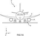
- Aircraft 10 comprises a fuselage 12, wings 14, cockpit controls 16, landing gear 18, and a propulsion system, such as gas turbine engines 20.
- aircraft 10 may include a cryogenic fuel auxiliary power system 200.
- Gas turbine engine 20 may be a two-spool turbofan that generally incorporates a fan section 22, a compressor section 24, a combustor section 26 and a turbine section 28.
- fan section 22 can drive air along a bypass flow-path B while compressor section 24 can drive air through a core flow-path C for compression and communication into combustor section 26 then expansion through turbine section 28.
- gas turbine engine 20 may incorporate a plurality of engine accessories such as, for example, components of power transfer system 200.
- turbofan gas turbine engine 20 Although depicted as a turbofan gas turbine engine 20 herein, it should be understood that the concepts described herein are not limited to use with turbofans as the teachings may be applied to other types of engines including turbojet engines, a low-bypass turbofans, a high bypass turbofans, reciprocating engines, or any other internal combustion engine known to those skilled in the art.
- Gas turbine engine 20 may generally comprise a low speed spool 30 and a high speed spool 32 mounted for rotation about an engine central longitudinal axis A-A' relative to an engine static structure 36 via one or more bearing systems 38 (shown as bearing system 38-1 and bearing system 38-2). It should be understood that various bearing systems 38 at various locations may alternatively or additionally be provided, including for example, bearing system 38, bearing system 38-1, and bearing system 38-2.
- Low speed spool 30 may generally comprise an inner shaft 40 that interconnects a fan 42, a low pressure (or first) compressor section 44 (also referred to a low pressure compressor) and a low pressure (or first) turbine section 46.
- Inner shaft 40 may be connected to fan 42 through a geared architecture 48 that can drive fan 42 at a lower speed than low speed spool 30.
- Geared architecture 48 may comprise a gear assembly 60 enclosed within a gear housing 62.
- Gear assembly 60 couples inner shaft 40 to a rotating fan structure.
- High speed spool 32 may comprise an outer shaft 50 that interconnects a high pressure compressor (“HPC") 52 (e.g., a second compressor section) and high pressure (or second) turbine section 54.
- HPC high pressure compressor
- a combustor 56 may be located between HPC 52 and high pressure turbine 54.
- a mid-turbine frame 57 of engine static structure 36 may be located generally between high pressure turbine 54 and low pressure turbine 46.
- Mid-turbine frame 57 may support one or more bearing systems 38 in turbine section 28.
- Inner shaft 40 and outer shaft 50 may be concentric and rotate via bearing systems 38 about the engine central longitudinal axis A-A', which is collinear with their longitudinal axes.
- a "high pressure" compressor or turbine experiences a higher pressure than a corresponding "low pressure” compressor or turbine.
- the core airflow C may be compressed by low pressure compressor 44 then HPC 52, mixed and burned with fuel in combustor 56, then expanded over high pressure turbine 54 and low pressure turbine 46.
- Mid-turbine frame 57 includes airfoils 59 which are in the core airflow path.
- Low pressure turbine 46, and high pressure turbine 54 rotationally drive the respective low speed spool 30 and high speed spool 32 in response to the expansion.
- Gas turbine engine 20 may be, for example, a high-bypass geared aircraft engine. In various embodiments, the bypass ratio of gas turbine engine 20 may be greater than about six (6). In various embodiments, the bypass ratio of gas turbine engine 20 may be greater than ten (10).
- geared architecture 48 may be an epicyclic gear train, such as a star gear system (sun gear in meshing engagement with a plurality of star gears supported by a carrier and in meshing engagement with a ring gear) or other gear system. Geared architecture 48 may have a gear reduction ratio of greater than about 2.3 and low pressure turbine 46 may have a pressure ratio that is greater than about 5. In various embodiments, the bypass ratio of gas turbine engine 20 is greater than about ten (10:1).
- the diameter of fan 42 may be significantly larger than that of the low pressure compressor 44, and the low pressure turbine 46 may have a pressure ratio that is greater than about (5:1). Low pressure turbine 46 pressure ratio may be measured prior to inlet of low pressure turbine 46 as related to the pressure at the outlet of low pressure turbine 46 prior to an exhaust nozzle. It should be understood, however, that the above parameters are exemplary of various embodiments of a suitable geared architecture engine and that the present disclosure contemplates other gas turbine engines including direct drive turbofans.
- the next generation of turbofan engines may be designed for higher efficiency which is associated with higher pressure ratios and higher temperatures in the HPC 52. These higher operating temperatures and pressure ratios may create operating environments that may cause thermal loads that are higher than the thermal loads encountered in conventional turbofan engines, which may shorten the operational life of current components.
- HPC 52 may comprise alternating rows of rotating rotors and stationary stators.
- Stators may have a cantilevered configuration or a shrouded configuration.
- a stator may comprise a stator vane, a casing support and a hub support.
- a stator vane may be supported along an outer diameter by a casing support and along an inner diameter by a hub support.
- a cantilevered stator may comprise a stator vane that is only retained and/or supported at the casing (e.g., along an outer diameter).
- rotors may be configured to compress and spin a fluid flow.
- Stators may be configured to receive and straighten the fluid flow.
- the fluid flow discharged from the trailing edge of stators may be straightened (e.g., the flow may be directed in a substantially parallel path to the centerline of the engine and/or HPC) to increase and/or improve the efficiency of the engine and, more specifically, to achieve maximum and/or near maximum compression and efficiency when the straightened air is compressed and spun by rotor 64.
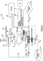
- System 200 is shown integrated with the gas turbine engine 20 of aircraft 10 according to various embodiments.
- System 200 includes a controller 202 which may be integrated into computer systems onboard aircraft 10.
- controller 202 may be configured as a central network element or hub to access various systems, engines, and components of system 200.
- Controller 202 may comprise a network, computer-based system, and/or software components configured to provide an access point to various systems, engines, and components of system 200.
- controller 202 may comprise a processor.
- controller 202 may be implemented in a single processor.
- controller 202 may be implemented as and may include one or more processors and/or one or more tangible, non-transitory memories and be capable of implementing logic.
- Each processor can be a general purpose processor, a digital signal processor (DSP), an application specific integrated circuit (ASIC), a field programmable gate array (FPGA) or other programmable logic device, discrete gate or transistor logic, discrete hardware components, or any combination thereof.
- Controller 202 may comprise a processor configured to implement various logical operations in response to execution of instructions, for example, instructions stored on a non-transitory, tangible, computer-readable medium configured to communicate with controller 202. In this regard, controller 202 may be configured to control various components of system 200 via control signals 208.
- System program instructions and/or controller instructions may be loaded onto a non-transitory, tangible computer-readable medium having instructions stored thereon that, in response to execution by a controller, cause the controller to perform various operations.
- non-transitory is to be understood to remove only propagating transitory signals per se and includes all standard computer-readable media that are not only propagating transitory signals per se.
- controller 202 may be in electronic communication with a pilot through a control interface 204 of cockpit controls 16, for example, a multifunction display, a switch panel, and/or the like which an operator can operate.
- the control interface 204 may enable the operator to interact with system 200 for example, to issue commands, display information such as, for example, warnings, or receive outputs.
- Control interface 204 may comprise any suitable combination of hardware, software, and/or database components.
- System 200 comprises one or more feedback elements to monitor and measure aircraft 10 and gas turbine engine 20 characteristics.
- controller 202 is in electronic communication with sensors 206 that may be coupled to or in direct electronic communication with aircraft systems such as, for example, propulsion systems, fuel systems (e.g., primary and/or cryogenic fuel systems), and/or the like.
- Controller 202 may be in electronic communication with the full suite of aircraft sensors and other data sources available within and without the aircraft 10.
- Sensors 206 may comprise a temperature sensor, a torque sensor, a speed sensor, a pressure sensor, a position sensor, an accelerometer, a voltmeter, an ammeter, a wattmeter, an optical sensor, or any other suitable measuring device known to those skilled in the art.
- Sensors 206 may be configured to transmit measurements to controller 202, thereby providing sensor feedback about the measured system.
- the sensor feedback may be, for example, a speed signal, or may be position feedback, temperature feedback, pressure feedback or other data.
- System 200 includes a cryogenic fuel supply 210 which may be configured to store a fuel such as a cryogenic liquid fuel.
- the fuel may be one of molecular hydrogen, methane, ethane, propane, butane, natural gas and/or the like.
- the secondary fuel supply 210 is in fluid communication with a bypass-control valve 212 (e.g., a first valve) via supply line 214.
- the bypass-control valve 212 is in fluid communication with a fuel cell 220 and is configured to control the fuel flow to a fuel cell 220.
- bypass-control valve 212 is in fluid communication with a primary heat exchanger 234 (i.e., a first heat exchanger) and is configured to distribute fuel flow to the primary heat exchanger 234.
- bypass-control valve 212 may distribute the fuel flow relatively between the fuel cell 220 and the primary heat exchanger 234 or may be configured to bypass the fuel cell 220.
- the primary heat exchanger 234 may extract heat from the gas turbine engine 20 and impart heat energy to the cryogenic fuel.
- the primary heat exchanger 234 is configured to vaporize and expand the cryogenic fuel and deliver heated gaseous fuel to a combustion chamber of the engine (e.g., combustor 56).
- the bypass-control valve 212 is in fluid communication with a secondary heat exchanger 218 (i.e., a second heat exchanger) configured to impart heat energy to the cryogenic fuel and provide heated fuel to the fuel cell 220.
- the fuel cell 220 may be electrically coupled to an electrical load 230 such as, for example, an electrical power system of aircraft 10. In response to receiving the fuel from the bypass-control valve 212, the fuel cell 220 may consume a portion of the fuel to generate electrical power and a byproduct such as, for example, liquid water.
- the electrical load 230 may be disconnected from the fuel cell 220 by, for example, an electrical load disconnect relay 232.
- the fuel cell 220 is in fluid communication with an isolation valve 228 (e.g., a second valve) and may pass an unused portion of the fuel to the isolation valve.
- the fuel cell 220 is in fluid communication with a byproduct storage tank 224.
- a transfer pump 222 e.g., a first pump
- waste water lines 226 e.g., a first pump
- Water storage tank 224 is in fluid communication with an injection valve 236 (e.g., a third valve) which is configured to regulate fluid communication between the byproduct storage tank 224 and the gas turbine engine 20.
- the injection valve 236 may thereby provide the byproduct to a mass injection system of the gas turbine engine configured to deliver the byproduct to a compressor stage, an intercooler, an aftercooler, a combustor, a turbine stage, and/or the like and thereby tend to improve the performance of the gas turbine engine 20.
- performance may be improved by an increase in mass flow along with an accompanying change in air temperature within the gas turbine due to a latent heat of evaporation of the injected byproduct (e.g., liquid water).
- a mass injection system may generate multiple beneficial effects including reducing the temperature of air compressed in engine 20's fan 42 and/or low pressure compressor 44 and/or high pressure compressor 52.
- system 200 may thereby enhance the durability and reliability of gas turbine engine 20 components.
- an injector pump 238 (e.g., a second pump) may be in fluid communication relatively between the injector valve 236 and the gas turbine engine 20.
- the injector pump 238 may be configured to increase the pressure of the byproduct above an operating pressure of the gas turbine engine 20.
- the byproduct storage tank 223 may include a fluid level sensor 240 in communication with the controller 202.
- the byproduct storage tank 224 may be in fluid communication with a drain valve 242 (e.g., a fourth valve) which may be controlled by controller 202 in response to a signal from the fluid level sensor 240.
- the controller 202 may tend to inhibit overfilling of the byproduct storage tank 224.
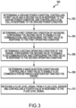
- Method 300 comprises determining a ground power condition, controlling the first valve and the second valve in response to the ground power condition, and controlling the fuel cell in response to the ground power condition (step 302).
- Method 300 includes determining a first operating condition of the engine, configuring the second valve to enable fluid communication between the fuel cell and the primary heat exchanger in response to the first operating condition, and configuring the first valve to supply a first portion of the fuel flow to the fuel cell and a second portion of the fuel flow to the primary heat exchanger in response to the first operating condition (step 304).
- Method 300 includes determining a second operating condition of the engine, configuring the second valve to inhibit fluid communication between the fuel cell and the primary heat exchanger in response to the second operating condition, and configuring the first valve to supply the fuel flow to the primary heat exchanger in response to the second operating condition (step 306).
- Method 300 includes determining a mass injection condition and controlling a third valve to enable fluid communication between the byproduct tank and the engine in response to the mass injection condition (step 308).
- method 300 includes receiving a fluid level signal from a fluid level sensor in electronic communication with the controller and controlling a fourth valve in response to the fluid level signal (step 310).
- references to "various embodiments,” “one embodiment,” “an embodiment,” “an example embodiment,” etc. indicate that the embodiment described may include a particular feature, structure, or characteristic, but every embodiment may not necessarily include the particular feature, structure, or characteristic. Moreover, such phrases are not necessarily referring to the same embodiment. Further, when a particular feature, structure, or characteristic is described in connection with an embodiment, it is submitted that it is within the knowledge of one skilled in the art to affect such feature, structure, or characteristic in connection with other embodiments whether or not explicitly described. After reading the description, it will be apparent to one skilled in the relevant art(s) how to implement the invention in alternative embodiments.
- the terms "comprises,” “comprising,” or any other variation thereof, are intended to cover a non-exclusive inclusion, such that a process, method, article, or apparatus that comprises a list of elements does not include only those elements but may include other elements not expressly listed or inherent to such process, method, article, or apparatus.
Landscapes
- Engineering & Computer Science (AREA)
- Chemical & Material Sciences (AREA)
- Combustion & Propulsion (AREA)
- Mechanical Engineering (AREA)
- General Engineering & Computer Science (AREA)
- Aviation & Aerospace Engineering (AREA)
- Fuel Cell (AREA)
- Engine Equipment That Uses Special Cycles (AREA)
Claims (15)
- Hilfsenergiesystem (200) für kryogenen Brennstoff für einen Motor (20), umfassend:eine kryogene Brennstoffversorgung (210);ein erstes Ventil (212), das in Fluidverbindung mit der kryogenen Brennstoffversorgung steht und dazu konfiguriert ist, einen Brennstofffluss zu steuern;einen ersten Wärmetauscher (234), der dazu konfiguriert ist, den Brennstoffstrom aufzunehmen, in Fluidverbindung mit dem ersten Ventil steht und dazu konfiguriert ist, in Fluidverbindung mit einer Brennkammer des Motors zu stehen;eine Brennstoffzelle (220) in Fluidverbindung zwischen dem ersten Ventil und dem ersten Wärmetauscher; ein zweites Ventil (228), das in Fluidverbindung mit der Brennstoffzelle und dem ersten Wärmetauscher steht und dazu konfiguriert ist, die Fluidverbindung zwischen diesen zu unterbrechen;einen zweiten Wärmetauscher (218) in Fluidverbindung zwischen dem ersten Ventil und der Brennstoffzelle;eine Steuereinrichtung (202);einen Sensor (206) in Kommunikationsverbindung mit der Steuereinrichtung, der dazu konfiguriert ist, eine Sensorrückmeldung bereitzustellen; undeinen greifbaren, nichtflüchtigen Speicher, der dazu konfiguriert ist, mit der Steuereinrichtung zu kommunizieren, wobei in dem greifbaren, nichtflüchtigen Speicher Anweisungen gespeichert sind, die als Reaktion auf die Ausführung durch die Steuereinrichtung die Steuereinrichtung veranlassen, Vorgänge durchzuführen, umfassend:Bestimmen einer Bodenstrombedingung durch die Steuereinrichtung;Steuern des ersten Ventils durch die Steuereinrichtung, um die Fluidverbindung zu ermöglichen, und des zweiten Ventils, um die Fluidverbindung als Reaktion auf die Bodenstrombedingung zu unterbrechen; undSteuern der Brennstoffzelle durch die Steuereinrichtung als Reaktion auf die Bodenstrombedingung.
- System (200) nach Anspruch 1, ferner umfassend eine Nebenproduktleitung in Fluidverbindung mit der Brennstoffzelle (220), die dazu konfiguriert ist, in Fluidverbindung mit einem Nebenproduktspeichertank (224) zu stehen, wobei die Brennstoffzelle dazu konfiguriert ist, als Reaktion auf die Aufnahme des Brennstoffflusses dem Nebenproduktspeichertank Nebenprodukt zuzuführen.
- System (200) nach Anspruch 2, ferner umfassend eine Transferpumpe (222) in Fluidverbindung zwischen der Brennstoffzelle (220) und dem Nebenproduktspeichertank.
- System (200) nach Anspruch 3, ferner umfassend ein drittes Ventil (236), das dazu konfiguriert ist, in Fluidverbindung zwischen dem Nebenproduktspeichertank und dem Motor zu stehen, wobei das dritte Ventil dazu konfiguriert ist, das Nebenprodukt einem Masseneinspritzsystem des Motors (20) zuzuführen.
- System (200) nach Anspruch 4, ferner umfassend eine zweite Pumpe (238) in Fluidverbindung zwischen dem dritten Ventil und dem Motor (20), wobei die zweite Pumpe dazu konfiguriert ist, den Druck des Nebenprodukts über einen Betriebsdruck des Motors hinaus zu erhöhen.
- System (200) nach Anspruch 4 oder 5, ferner umfassend ein viertes Ventil in Fluidverbindung zwischen dem Nebenproduktspeichertank und einem Abfluss.
- System (200) nach einem der vorhergehenden Ansprüche, ferner umfassend:Bestimmen einer ersten Betriebsbedingung des Motors (20) durch die Steuereinrichtung (202);Konfigurieren des zweiten Ventils (228) durch die Steuereinrichtung, um als Reaktion auf die erste Betriebsbedingung eine Fluidverbindung zwischen der Brennstoffzelle (220) und dem ersten Wärmetauscher (234) zu ermöglichen; undKonfigurieren des ersten Ventils (212) durch die Steuereinrichtung, um als Reaktion auf die erste Betriebsbedingung einen ersten Teil des Brennstoffstroms der Brennstoffzelle und einen zweiten Teil des Brennstoffstroms dem ersten Wärmetauscher zuzuführen.
- System (200) nach Anspruch 7, wobei die Vorgänge ferner umfassen:Bestimmen einer zweiten Betriebsbedingung des Motors (20) durch die Steuereinrichtung (202);Konfigurieren des zweiten Ventils (228) durch die Steuereinrichtung, um als Reaktion auf die zweite Betriebsbedingung eine Fluidverbindung zwischen der Brennstoffzelle (220) und dem ersten Wärmetauscher (234) zu unterbinden; undKonfigurieren des ersten Ventils (212) durch die Steuereinrichtung, um als Reaktion auf die zweite Betriebsbedingung den Brennstoffstrom dem ersten Wärmetauscher zuzuführen.
- System (200) nach Anspruch 8, wobei die Vorgänge ferner umfassen:Bestimmen einer Masseneinspritzbedingung durch die Steuereinrichtung (202); undSteuern des dritten Ventils durch die Steuereinrichtung, um als Reaktion auf die Masseneinspritzbedingung eine Fluidverbindung zwischen dem Nebenproduktspeichertank und dem Motor zu ermöglichen.
- System (200) nach Anspruch 9, wobei die Vorgänge ferner umfassen:Empfangen eines Fluidpegelsignals von einem Fluidpegelsensor in elektronischer Kommunikationsverbindung mit der Steuereinrichtung durch die Steuereinrichtung (202); undSteuern des vierten Ventils durch die Steuereinrichtung als Reaktion auf das Fluidpegelsignal.
- Verfahren zum Steuern eines Hilfsenergiesystems (200) für kryogenen Brennstoff für einen Motor (20) nach Anspruch 1, wobei das Verfahren umfasst:Bestimmen einer Bodenstrombedingung durch eine Steuereinrichtung (202);Steuern des ersten Ventils (212) und des zweiten Ventils (228) durch die Steuereinrichtung als Reaktion auf die Bodenstrombedingung; undSteuern der Brennstoffzelle (220) durch die Steuereinrichtung als Reaktion auf die Bodenstrombedingung.
- Verfahren nach Anspruch 11, ferner umfassend:Bestimmen einer ersten Betriebsbedingung des Motors (20) durch die Steuereinrichtung (202);Konfigurieren des zweiten Ventils (228) durch die Steuereinrichtung, um als Reaktion auf die erste Betriebsbedingung eine Fluidverbindung zwischen der Brennstoffzelle (220) und dem ersten Wärmetauscher (234) zu ermöglichen; undKonfigurieren des ersten Ventils (212) durch die Steuereinrichtung, um als Reaktion auf die erste Betriebsbedingung einen ersten Teil eines Brennstoffstroms der Brennstoffzelle und einen zweiten Teil des Brennstoffstroms dem ersten Wärmetauscher zuzuführen.
- Verfahren nach Anspruch 12, ferner umfassend:Bestimmen einer zweiten Betriebsbedingung des Motors (20) durch die Steuereinrichtung (202);Konfigurieren des zweiten Ventils (228) durch die Steuereinrichtung, um als Reaktion auf die zweite Betriebsbedingung eine Fluidverbindung zwischen der Brennstoffzelle (220) und dem ersten Wärmetauscher (234) zu unterbinden; undKonfigurieren des ersten Ventils (212) durch die Steuereinrichtung, um als Reaktion auf die zweite Betriebsbedingung den Brennstoffstrom dem ersten Wärmetauscher zuzuführen.
- Herstellungsartikel, der ein physisches, nichtflüchtiges computerlesbares Speichermedium beinhaltet, das darauf gespeicherte Anweisungen aufweist, die als Reaktion auf die Ausführung durch einen Prozessor den Prozessor dazu veranlassen, Vorgänge zum Steuern eines Hilfsenergiesystems (200) für kryogenen Brennstoff für einen Motor (20) nach Anspruch 1 durchzuführen, wobei die Vorgänge umfassen:Bestimmen einer Bodenstrombedingung durch den Prozessor;Steuern des ersten Ventils (212) und des zweiten Ventils (228) durch den Prozessor als Reaktion auf die Bodenstrombedingung; undSteuern der Brennstoffzelle (220) durch den Prozessor als Reaktion auf die Bodenstrombedingung.
- Herstellungsartikel nach Anspruch 14, wobei die Vorgänge ferner umfassen:Bestimmen einer ersten Betriebsbedingung des Motors (20) durch den Prozessor;Konfigurieren des zweiten Ventils (228) durch den Prozessor, um eine Fluidverbindung zwischen der Brennstoffzelle (220) und dem ersten Wärmetauscher (234) als Reaktion auf die erste Betriebsbedingung zu ermöglichen; UndKonfigurieren des ersten Ventils (212) durch den Prozessor, um als Reaktion auf die erste Betriebsbedingung einen ersten Teil des Brennstoffstroms der Brennstoffzelle und einen zweiten Teil des Brennstoffstroms dem ersten Wärmetauscher zuzuführen,wobei die Vorgänge optional ferner umfassen:Bestimmen eines zweiten Betriebszustands des Motors durch den Prozessor;Konfigurieren des zweiten Ventils durch den Prozessor, um als Reaktion auf die zweite Betriebsbedingung eine Fluidverbindung zwischen der Brennstoffzelle und dem ersten Wärmetauscher zu unterbinden; undKonfigurieren des ersten Ventils durch den Prozessor, um als Reaktion auf die zweite Betriebsbedingung den Brennstoffstrom dem ersten Wärmetauscher zuzuführen,wobei die Vorgänge optional ferner umfassen:Bestimmen einer Masseneinspritzbedingung durch den Prozessor; undSteuern eines dritten Ventils durch den Prozessor, um als Reaktion auf die Masseneinspritzbedingung eine Fluidverbindung zwischen einem Nebenproduktspeichertank und dem Motor zu ermöglichen.
Applications Claiming Priority (1)
| Application Number | Priority Date | Filing Date | Title |
|---|---|---|---|
| US16/732,774 US20210207540A1 (en) | 2020-01-02 | 2020-01-02 | Systems and methods for fuel cell auxiliary power in secondary fuel applications |
Publications (2)
| Publication Number | Publication Date |
|---|---|
| EP3845747A1 EP3845747A1 (de) | 2021-07-07 |
| EP3845747B1 true EP3845747B1 (de) | 2023-10-11 |
Family
ID=74003788
Family Applications (1)
| Application Number | Title | Priority Date | Filing Date |
|---|---|---|---|
| EP20217693.9A Active EP3845747B1 (de) | 2020-01-02 | 2020-12-29 | Systeme und verfahren zur brennstoffzellen-hilfsenergie in sekundären brennstoffanwendungen |
Country Status (2)
| Country | Link |
|---|---|
| US (1) | US20210207540A1 (de) |
| EP (1) | EP3845747B1 (de) |
Families Citing this family (22)
| Publication number | Priority date | Publication date | Assignee | Title |
|---|---|---|---|---|
| FR3120828A1 (fr) * | 2021-03-17 | 2022-09-23 | Airbus Operations (S.A.S.) | Système de stockage d’hydrogène et aéronef comprenant un système de stockage d’hydrogène. |
| WO2022245427A2 (en) * | 2021-03-31 | 2022-11-24 | Zeroavia Ltd. | Refueling system for hydrogen fuel cell-powered aircraft |
| US20230010158A1 (en) * | 2021-07-09 | 2023-01-12 | Raytheon Technologies Corporation | Hydrogen powered geared turbofan engine with reduced size core engine |
| US20230083470A1 (en) * | 2021-09-10 | 2023-03-16 | Hamilton Sundstrand Corporation | Cryogenic fuel cooled ecs precooler |
| FR3128488B1 (fr) * | 2021-10-25 | 2024-01-12 | Safran | Système de conditionnement de carburant pour alimenter une turbomachine d’aéronef, aéronef et procédé d’utilisation |
| FR3128738B1 (fr) | 2021-10-29 | 2024-01-12 | Safran | Système de conditionnement de carburant pour alimenter une turbomachine d’aéronef, procédé d’alimentation d’une turbomachine |
| US12169069B2 (en) * | 2021-12-20 | 2024-12-17 | General Electric Company | System for producing diluent for a gas turbine engine |
| US20230223572A1 (en) * | 2022-01-10 | 2023-07-13 | General Electric Company | Power source for an aircraft |
| US11967743B2 (en) * | 2022-02-21 | 2024-04-23 | General Electric Company | Modular fuel cell assembly |
| FR3134849B1 (fr) * | 2022-04-26 | 2025-02-21 | Safran | Système de contrôle de la température d’un fluide caloporteur dans une boucle de circulation, procédé de contrôle de la température |
| US12006878B2 (en) | 2022-05-04 | 2024-06-11 | General Electric Company | Methods and apparatus to operate gas turbines with hydrogen as the combusting fuel |
| EP4283176B1 (de) * | 2022-05-24 | 2025-03-26 | Airbus Operations GmbH | Rohr zum erhitzen eines kryogenen flüssiggases und verfahren zum produzieren desselben |
| US12006866B2 (en) | 2022-07-08 | 2024-06-11 | Rtx Corporation | Hybrid electric hydrogen engine for aircraft |
| US12071257B2 (en) | 2022-07-08 | 2024-08-27 | Rtx Corporation | Hybrid electric hydrogen engine for aircraft |
| US11898491B1 (en) * | 2022-07-21 | 2024-02-13 | Rtx Corporation | Water pressure and quantity monitoring for hydrogen steam injected and inter-cooled turbine engine |
| GB202215721D0 (en) | 2022-10-24 | 2022-12-07 | Rolls Royce Plc | Gas turbine engine fuel system |
| GB202215722D0 (en) | 2022-10-24 | 2022-12-07 | Rolls Royce Plc | Combined gas turbine engine and fuel cell |
| US20240253807A1 (en) * | 2023-01-30 | 2024-08-01 | The Boeing Company | Load-alleviation systems for aircraft having centrally stored fuel |
| EP4501796A1 (de) * | 2023-07-31 | 2025-02-05 | Airbus Operations, S.L.U. | Klimatisierungssystem für ein flugzeug |
| US12269606B2 (en) | 2023-09-01 | 2025-04-08 | The Boeing Company | Aircraft |
| US20260036090A1 (en) * | 2024-08-02 | 2026-02-05 | Rtx Corporation | Cryogenic fuel start up system |
| US12460580B1 (en) * | 2024-12-13 | 2025-11-04 | Pratt & Whitney Canada Corp. | Heat management system and method for hydrogen-fueled engine |
Citations (2)
| Publication number | Priority date | Publication date | Assignee | Title |
|---|---|---|---|---|
| US20020043064A1 (en) * | 2000-10-13 | 2002-04-18 | Griffin Timothy Albert | Method for operating a power plant |
| US20150308297A1 (en) * | 2012-11-13 | 2015-10-29 | Mitsubishi Hitachi Power Systems, Ltd. | Power generation system and method for operating power generation system |
Family Cites Families (11)
| Publication number | Priority date | Publication date | Assignee | Title |
|---|---|---|---|---|
| US3775976A (en) * | 1972-05-26 | 1973-12-04 | Us Navy | Lox heat sink system for underwater thermal propulsion system |
| US6148602A (en) * | 1998-08-12 | 2000-11-21 | Norther Research & Engineering Corporation | Solid-fueled power generation system with carbon dioxide sequestration and method therefor |
| WO2009040112A2 (en) * | 2007-09-25 | 2009-04-02 | Eads Deutschland Gmbh | Method for operating a gas turbine engine, power supplying device for conducting such method and aircraft using such method |
| US9188061B2 (en) * | 2011-10-24 | 2015-11-17 | General Electric Company | System for turbine combustor fuel assembly |
| JP5768897B2 (ja) * | 2011-12-09 | 2015-08-26 | トヨタ自動車株式会社 | 内燃機関 |
| BR112015015561A2 (pt) * | 2012-12-28 | 2017-07-11 | Gen Electric | composições de combustível criogênico e sistema de aeronave bicombustível |
| JP6099408B2 (ja) * | 2013-01-18 | 2017-03-22 | 三菱日立パワーシステムズ株式会社 | 発電システム、及び発電システムの運転方法 |
| US9604730B2 (en) * | 2014-03-27 | 2017-03-28 | Honeywell International Inc. | Aircraft systems and methods with integrated tank inerting and power generation |
| WO2017001411A1 (en) * | 2015-06-29 | 2017-01-05 | Ge Aviation Systems Limited | Fuel cell emergency power system for an aircraft |
| US9941526B2 (en) * | 2015-08-21 | 2018-04-10 | The Boeing Company | Inert gas generation from fuel cells |
| FR3052440B1 (fr) * | 2016-06-13 | 2018-05-18 | Safran Helicopter Engines | Integration d'un materiau a changement de phase pour limiter la temperature du carburant a partir d'un module electronique. |
-
2020
- 2020-01-02 US US16/732,774 patent/US20210207540A1/en not_active Abandoned
- 2020-12-29 EP EP20217693.9A patent/EP3845747B1/de active Active
Patent Citations (2)
| Publication number | Priority date | Publication date | Assignee | Title |
|---|---|---|---|---|
| US20020043064A1 (en) * | 2000-10-13 | 2002-04-18 | Griffin Timothy Albert | Method for operating a power plant |
| US20150308297A1 (en) * | 2012-11-13 | 2015-10-29 | Mitsubishi Hitachi Power Systems, Ltd. | Power generation system and method for operating power generation system |
Also Published As
| Publication number | Publication date |
|---|---|
| US20210207540A1 (en) | 2021-07-08 |
| EP3845747A1 (de) | 2021-07-07 |
Similar Documents
| Publication | Publication Date | Title |
|---|---|---|
| EP3845747B1 (de) | Systeme und verfahren zur brennstoffzellen-hilfsenergie in sekundären brennstoffanwendungen | |
| US12345204B2 (en) | Methods for power transfer in cryogenic fuel applications | |
| US11674443B2 (en) | Hydrogen fuel system | |
| EP3995679B1 (de) | Wasserstoffbrennstoffsystem | |
| US20160053691A1 (en) | Gas turbine engine system | |
| US20210207544A1 (en) | Low spool power extraction via multiple generators | |
| CN110566289B (zh) | 操作涡轮机械的方法 | |
| US20240425188A1 (en) | Testing secondary power system of aircraft powerplant | |
| US12012896B2 (en) | Crossover cooling flow for multi-engine systems | |
| US11873768B1 (en) | Hydrogen fuel system for a gas turbine engine | |
| US20200096331A1 (en) | Anti-rotation method for angled face cap probe | |
| US11905884B1 (en) | Hydrogen fuel system for a gas turbine engine | |
| US20250116208A1 (en) | Lubrication system for a turbine engine | |
| EP4431399B1 (de) | Flugzeugkraftstoffsystem mit abnehmbarem kraftstofftank | |
| EP3450725B1 (de) | Konservierungssystem für ein integriertes brennstoffpumpen- und kontrollsystem | |
| US12583609B2 (en) | Exhaust duct for hybrid aircraft powerplant | |
| RU2379532C1 (ru) | Атомный газотурбинный авиационный двигатель | |
| US20250327426A1 (en) | Monitoring fuel phase in aircraft powerplant fuel system | |
| US12454913B2 (en) | Gas turbine engine component with integral heat exchanger | |
| US12359623B1 (en) | Hydrogen turboexpander for use in an aviation propulsion system | |
| US20260104009A1 (en) | Enhanced recuperation cycle for aircraft powerplant turbine engine | |
| US20250084792A1 (en) | Fuel containment structure for engine fuel delivery system | |
| CA3270160A1 (en) | Hydrogen turboexpander for use in an aviation propulsion system |
Legal Events
| Date | Code | Title | Description |
|---|---|---|---|
| PUAI | Public reference made under article 153(3) epc to a published international application that has entered the european phase |
Free format text: ORIGINAL CODE: 0009012 |
|
| STAA | Information on the status of an ep patent application or granted ep patent |
Free format text: STATUS: THE APPLICATION HAS BEEN PUBLISHED |
|
| AK | Designated contracting states |
Kind code of ref document: A1 Designated state(s): AL AT BE BG CH CY CZ DE DK EE ES FI FR GB GR HR HU IE IS IT LI LT LU LV MC MK MT NL NO PL PT RO RS SE SI SK SM TR |
|
| STAA | Information on the status of an ep patent application or granted ep patent |
Free format text: STATUS: REQUEST FOR EXAMINATION WAS MADE |
|
| 17P | Request for examination filed |
Effective date: 20220107 |
|
| RBV | Designated contracting states (corrected) |
Designated state(s): AL AT BE BG CH CY CZ DE DK EE ES FI FR GB GR HR HU IE IS IT LI LT LU LV MC MK MT NL NO PL PT RO RS SE SI SK SM TR |
|
| GRAP | Despatch of communication of intention to grant a patent |
Free format text: ORIGINAL CODE: EPIDOSNIGR1 |
|
| STAA | Information on the status of an ep patent application or granted ep patent |
Free format text: STATUS: GRANT OF PATENT IS INTENDED |
|
| INTG | Intention to grant announced |
Effective date: 20230425 |
|
| GRAS | Grant fee paid |
Free format text: ORIGINAL CODE: EPIDOSNIGR3 |
|
| GRAA | (expected) grant |
Free format text: ORIGINAL CODE: 0009210 |
|
| STAA | Information on the status of an ep patent application or granted ep patent |
Free format text: STATUS: THE PATENT HAS BEEN GRANTED |
|
| AK | Designated contracting states |
Kind code of ref document: B1 Designated state(s): AL AT BE BG CH CY CZ DE DK EE ES FI FR GB GR HR HU IE IS IT LI LT LU LV MC MK MT NL NO PL PT RO RS SE SI SK SM TR |
|
| REG | Reference to a national code |
Ref country code: GB Ref legal event code: FG4D |
|
| REG | Reference to a national code |
Ref country code: CH Ref legal event code: EP |
|
| RAP4 | Party data changed (patent owner data changed or rights of a patent transferred) |
Owner name: RTX CORPORATION |
|
| REG | Reference to a national code |
Ref country code: DE Ref legal event code: R096 Ref document number: 602020019007 Country of ref document: DE |
|
| REG | Reference to a national code |
Ref country code: IE Ref legal event code: FG4D |
|
| REG | Reference to a national code |
Ref country code: LT Ref legal event code: MG9D |
|
| REG | Reference to a national code |
Ref country code: NL Ref legal event code: MP Effective date: 20231011 |
|
| REG | Reference to a national code |
Ref country code: AT Ref legal event code: MK05 Ref document number: 1620430 Country of ref document: AT Kind code of ref document: T Effective date: 20231011 |
|
| PG25 | Lapsed in a contracting state [announced via postgrant information from national office to epo] |
Ref country code: NL Free format text: LAPSE BECAUSE OF FAILURE TO SUBMIT A TRANSLATION OF THE DESCRIPTION OR TO PAY THE FEE WITHIN THE PRESCRIBED TIME-LIMIT Effective date: 20231011 |
|
| PG25 | Lapsed in a contracting state [announced via postgrant information from national office to epo] |
Ref country code: GR Free format text: LAPSE BECAUSE OF FAILURE TO SUBMIT A TRANSLATION OF THE DESCRIPTION OR TO PAY THE FEE WITHIN THE PRESCRIBED TIME-LIMIT Effective date: 20240112 |
|
| PG25 | Lapsed in a contracting state [announced via postgrant information from national office to epo] |
Ref country code: IS Free format text: LAPSE BECAUSE OF FAILURE TO SUBMIT A TRANSLATION OF THE DESCRIPTION OR TO PAY THE FEE WITHIN THE PRESCRIBED TIME-LIMIT Effective date: 20240211 |
|
| PG25 | Lapsed in a contracting state [announced via postgrant information from national office to epo] |
Ref country code: LT Free format text: LAPSE BECAUSE OF FAILURE TO SUBMIT A TRANSLATION OF THE DESCRIPTION OR TO PAY THE FEE WITHIN THE PRESCRIBED TIME-LIMIT Effective date: 20231011 |
|
| PG25 | Lapsed in a contracting state [announced via postgrant information from national office to epo] |
Ref country code: AT Free format text: LAPSE BECAUSE OF FAILURE TO SUBMIT A TRANSLATION OF THE DESCRIPTION OR TO PAY THE FEE WITHIN THE PRESCRIBED TIME-LIMIT Effective date: 20231011 |
|
| PG25 | Lapsed in a contracting state [announced via postgrant information from national office to epo] |
Ref country code: ES Free format text: LAPSE BECAUSE OF FAILURE TO SUBMIT A TRANSLATION OF THE DESCRIPTION OR TO PAY THE FEE WITHIN THE PRESCRIBED TIME-LIMIT Effective date: 20231011 |
|
| PG25 | Lapsed in a contracting state [announced via postgrant information from national office to epo] |
Ref country code: LT Free format text: LAPSE BECAUSE OF FAILURE TO SUBMIT A TRANSLATION OF THE DESCRIPTION OR TO PAY THE FEE WITHIN THE PRESCRIBED TIME-LIMIT Effective date: 20231011 Ref country code: IS Free format text: LAPSE BECAUSE OF FAILURE TO SUBMIT A TRANSLATION OF THE DESCRIPTION OR TO PAY THE FEE WITHIN THE PRESCRIBED TIME-LIMIT Effective date: 20240211 Ref country code: GR Free format text: LAPSE BECAUSE OF FAILURE TO SUBMIT A TRANSLATION OF THE DESCRIPTION OR TO PAY THE FEE WITHIN THE PRESCRIBED TIME-LIMIT Effective date: 20240112 Ref country code: ES Free format text: LAPSE BECAUSE OF FAILURE TO SUBMIT A TRANSLATION OF THE DESCRIPTION OR TO PAY THE FEE WITHIN THE PRESCRIBED TIME-LIMIT Effective date: 20231011 Ref country code: BG Free format text: LAPSE BECAUSE OF FAILURE TO SUBMIT A TRANSLATION OF THE DESCRIPTION OR TO PAY THE FEE WITHIN THE PRESCRIBED TIME-LIMIT Effective date: 20240111 Ref country code: AT Free format text: LAPSE BECAUSE OF FAILURE TO SUBMIT A TRANSLATION OF THE DESCRIPTION OR TO PAY THE FEE WITHIN THE PRESCRIBED TIME-LIMIT Effective date: 20231011 Ref country code: PT Free format text: LAPSE BECAUSE OF FAILURE TO SUBMIT A TRANSLATION OF THE DESCRIPTION OR TO PAY THE FEE WITHIN THE PRESCRIBED TIME-LIMIT Effective date: 20240212 |
|
| PG25 | Lapsed in a contracting state [announced via postgrant information from national office to epo] |
Ref country code: SE Free format text: LAPSE BECAUSE OF FAILURE TO SUBMIT A TRANSLATION OF THE DESCRIPTION OR TO PAY THE FEE WITHIN THE PRESCRIBED TIME-LIMIT Effective date: 20231011 Ref country code: RS Free format text: LAPSE BECAUSE OF FAILURE TO SUBMIT A TRANSLATION OF THE DESCRIPTION OR TO PAY THE FEE WITHIN THE PRESCRIBED TIME-LIMIT Effective date: 20231011 Ref country code: PL Free format text: LAPSE BECAUSE OF FAILURE TO SUBMIT A TRANSLATION OF THE DESCRIPTION OR TO PAY THE FEE WITHIN THE PRESCRIBED TIME-LIMIT Effective date: 20231011 Ref country code: NO Free format text: LAPSE BECAUSE OF FAILURE TO SUBMIT A TRANSLATION OF THE DESCRIPTION OR TO PAY THE FEE WITHIN THE PRESCRIBED TIME-LIMIT Effective date: 20240111 Ref country code: LV Free format text: LAPSE BECAUSE OF FAILURE TO SUBMIT A TRANSLATION OF THE DESCRIPTION OR TO PAY THE FEE WITHIN THE PRESCRIBED TIME-LIMIT Effective date: 20231011 Ref country code: HR Free format text: LAPSE BECAUSE OF FAILURE TO SUBMIT A TRANSLATION OF THE DESCRIPTION OR TO PAY THE FEE WITHIN THE PRESCRIBED TIME-LIMIT Effective date: 20231011 |
|
| PG25 | Lapsed in a contracting state [announced via postgrant information from national office to epo] |
Ref country code: DK Free format text: LAPSE BECAUSE OF FAILURE TO SUBMIT A TRANSLATION OF THE DESCRIPTION OR TO PAY THE FEE WITHIN THE PRESCRIBED TIME-LIMIT Effective date: 20231011 |
|
| REG | Reference to a national code |
Ref country code: DE Ref legal event code: R097 Ref document number: 602020019007 Country of ref document: DE |
|
| PG25 | Lapsed in a contracting state [announced via postgrant information from national office to epo] |
Ref country code: CZ Free format text: LAPSE BECAUSE OF FAILURE TO SUBMIT A TRANSLATION OF THE DESCRIPTION OR TO PAY THE FEE WITHIN THE PRESCRIBED TIME-LIMIT Effective date: 20231011 |
|
| PG25 | Lapsed in a contracting state [announced via postgrant information from national office to epo] |
Ref country code: SK Free format text: LAPSE BECAUSE OF FAILURE TO SUBMIT A TRANSLATION OF THE DESCRIPTION OR TO PAY THE FEE WITHIN THE PRESCRIBED TIME-LIMIT Effective date: 20231011 |
|
| PG25 | Lapsed in a contracting state [announced via postgrant information from national office to epo] |
Ref country code: SM Free format text: LAPSE BECAUSE OF FAILURE TO SUBMIT A TRANSLATION OF THE DESCRIPTION OR TO PAY THE FEE WITHIN THE PRESCRIBED TIME-LIMIT Effective date: 20231011 Ref country code: SK Free format text: LAPSE BECAUSE OF FAILURE TO SUBMIT A TRANSLATION OF THE DESCRIPTION OR TO PAY THE FEE WITHIN THE PRESCRIBED TIME-LIMIT Effective date: 20231011 Ref country code: RO Free format text: LAPSE BECAUSE OF FAILURE TO SUBMIT A TRANSLATION OF THE DESCRIPTION OR TO PAY THE FEE WITHIN THE PRESCRIBED TIME-LIMIT Effective date: 20231011 Ref country code: IT Free format text: LAPSE BECAUSE OF FAILURE TO SUBMIT A TRANSLATION OF THE DESCRIPTION OR TO PAY THE FEE WITHIN THE PRESCRIBED TIME-LIMIT Effective date: 20231011 Ref country code: EE Free format text: LAPSE BECAUSE OF FAILURE TO SUBMIT A TRANSLATION OF THE DESCRIPTION OR TO PAY THE FEE WITHIN THE PRESCRIBED TIME-LIMIT Effective date: 20231011 Ref country code: DK Free format text: LAPSE BECAUSE OF FAILURE TO SUBMIT A TRANSLATION OF THE DESCRIPTION OR TO PAY THE FEE WITHIN THE PRESCRIBED TIME-LIMIT Effective date: 20231011 Ref country code: CZ Free format text: LAPSE BECAUSE OF FAILURE TO SUBMIT A TRANSLATION OF THE DESCRIPTION OR TO PAY THE FEE WITHIN THE PRESCRIBED TIME-LIMIT Effective date: 20231011 |
|
| REG | Reference to a national code |
Ref country code: CH Ref legal event code: PL |
|
| PLBE | No opposition filed within time limit |
Free format text: ORIGINAL CODE: 0009261 |
|
| STAA | Information on the status of an ep patent application or granted ep patent |
Free format text: STATUS: NO OPPOSITION FILED WITHIN TIME LIMIT |
|
| PG25 | Lapsed in a contracting state [announced via postgrant information from national office to epo] |
Ref country code: LU Free format text: LAPSE BECAUSE OF NON-PAYMENT OF DUE FEES Effective date: 20231229 |
|
| PG25 | Lapsed in a contracting state [announced via postgrant information from national office to epo] |
Ref country code: MC Free format text: LAPSE BECAUSE OF FAILURE TO SUBMIT A TRANSLATION OF THE DESCRIPTION OR TO PAY THE FEE WITHIN THE PRESCRIBED TIME-LIMIT Effective date: 20231011 |
|
| REG | Reference to a national code |
Ref country code: BE Ref legal event code: MM Effective date: 20231231 |
|
| PG25 | Lapsed in a contracting state [announced via postgrant information from national office to epo] |
Ref country code: MC Free format text: LAPSE BECAUSE OF FAILURE TO SUBMIT A TRANSLATION OF THE DESCRIPTION OR TO PAY THE FEE WITHIN THE PRESCRIBED TIME-LIMIT Effective date: 20231011 Ref country code: LU Free format text: LAPSE BECAUSE OF NON-PAYMENT OF DUE FEES Effective date: 20231229 |
|
| 26N | No opposition filed |
Effective date: 20240712 |
|
| REG | Reference to a national code |
Ref country code: IE Ref legal event code: MM4A |
|
| PG25 | Lapsed in a contracting state [announced via postgrant information from national office to epo] |
Ref country code: IE Free format text: LAPSE BECAUSE OF NON-PAYMENT OF DUE FEES Effective date: 20231229 |
|
| PG25 | Lapsed in a contracting state [announced via postgrant information from national office to epo] |
Ref country code: BE Free format text: LAPSE BECAUSE OF NON-PAYMENT OF DUE FEES Effective date: 20231231 |
|
| PG25 | Lapsed in a contracting state [announced via postgrant information from national office to epo] |
Ref country code: CH Free format text: LAPSE BECAUSE OF NON-PAYMENT OF DUE FEES Effective date: 20231231 |
|
| PG25 | Lapsed in a contracting state [announced via postgrant information from national office to epo] |
Ref country code: SI Free format text: LAPSE BECAUSE OF FAILURE TO SUBMIT A TRANSLATION OF THE DESCRIPTION OR TO PAY THE FEE WITHIN THE PRESCRIBED TIME-LIMIT Effective date: 20231011 |
|
| PG25 | Lapsed in a contracting state [announced via postgrant information from national office to epo] |
Ref country code: SI Free format text: LAPSE BECAUSE OF FAILURE TO SUBMIT A TRANSLATION OF THE DESCRIPTION OR TO PAY THE FEE WITHIN THE PRESCRIBED TIME-LIMIT Effective date: 20231011 Ref country code: IE Free format text: LAPSE BECAUSE OF NON-PAYMENT OF DUE FEES Effective date: 20231229 Ref country code: CH Free format text: LAPSE BECAUSE OF NON-PAYMENT OF DUE FEES Effective date: 20231231 Ref country code: BE Free format text: LAPSE BECAUSE OF NON-PAYMENT OF DUE FEES Effective date: 20231231 |
|
| PG25 | Lapsed in a contracting state [announced via postgrant information from national office to epo] |
Ref country code: FI Free format text: LAPSE BECAUSE OF FAILURE TO SUBMIT A TRANSLATION OF THE DESCRIPTION OR TO PAY THE FEE WITHIN THE PRESCRIBED TIME-LIMIT Effective date: 20231011 |
|
| PG25 | Lapsed in a contracting state [announced via postgrant information from national office to epo] |
Ref country code: CY Free format text: LAPSE BECAUSE OF FAILURE TO SUBMIT A TRANSLATION OF THE DESCRIPTION OR TO PAY THE FEE WITHIN THE PRESCRIBED TIME-LIMIT; INVALID AB INITIO Effective date: 20201229 |
|
| PG25 | Lapsed in a contracting state [announced via postgrant information from national office to epo] |
Ref country code: HU Free format text: LAPSE BECAUSE OF FAILURE TO SUBMIT A TRANSLATION OF THE DESCRIPTION OR TO PAY THE FEE WITHIN THE PRESCRIBED TIME-LIMIT; INVALID AB INITIO Effective date: 20201229 |
|
| REG | Reference to a national code |
Ref country code: DE Ref legal event code: R081 Ref document number: 602020019007 Country of ref document: DE Owner name: RTX CORPORATION (N.D.GES.D. STAATES DELAWARE),, US Free format text: FORMER OWNER: RAYTHEON TECHNOLOGIES CORPORATION, FARMINGTON, CT, US |
|
| PG25 | Lapsed in a contracting state [announced via postgrant information from national office to epo] |
Ref country code: TR Free format text: LAPSE BECAUSE OF FAILURE TO SUBMIT A TRANSLATION OF THE DESCRIPTION OR TO PAY THE FEE WITHIN THE PRESCRIBED TIME-LIMIT Effective date: 20231011 |
|
| PGFP | Annual fee paid to national office [announced via postgrant information from national office to epo] |
Ref country code: DE Payment date: 20251126 Year of fee payment: 6 |
|
| PGFP | Annual fee paid to national office [announced via postgrant information from national office to epo] |
Ref country code: GB Payment date: 20251120 Year of fee payment: 6 |
|
| PGFP | Annual fee paid to national office [announced via postgrant information from national office to epo] |
Ref country code: FR Payment date: 20251120 Year of fee payment: 6 |
|
| P01 | Opt-out of the competence of the unified patent court (upc) registered |
Free format text: CASE NUMBER: UPC_APP_0018767_3845747/2025 Effective date: 20251221 |