EP3854358A1 - Knee joint bandage - Google Patents
Knee joint bandage Download PDFInfo
- Publication number
- EP3854358A1 EP3854358A1 EP21150861.9A EP21150861A EP3854358A1 EP 3854358 A1 EP3854358 A1 EP 3854358A1 EP 21150861 A EP21150861 A EP 21150861A EP 3854358 A1 EP3854358 A1 EP 3854358A1
- Authority
- EP
- European Patent Office
- Prior art keywords
- pad
- bandage
- knee joint
- base body
- patellar tendon
- Prior art date
- Legal status (The legal status is an assumption and is not a legal conclusion. Google has not performed a legal analysis and makes no representation as to the accuracy of the status listed.)
- Withdrawn
Links
Images


Classifications
-
- A—HUMAN NECESSITIES
- A61—MEDICAL OR VETERINARY SCIENCE; HYGIENE
- A61F—FILTERS IMPLANTABLE INTO BLOOD VESSELS; PROSTHESES; DEVICES PROVIDING PATENCY TO, OR PREVENTING COLLAPSING OF, TUBULAR STRUCTURES OF THE BODY, e.g. STENTS; ORTHOPAEDIC, NURSING OR CONTRACEPTIVE DEVICES; FOMENTATION; TREATMENT OR PROTECTION OF EYES OR EARS; BANDAGES, DRESSINGS OR ABSORBENT PADS; FIRST-AID KITS
- A61F5/00—Orthopaedic methods or devices for non-surgical treatment of bones or joints; Nursing devices; Anti-rape devices
- A61F5/01—Orthopaedic devices, e.g. splints, casts or braces
- A61F5/0102—Orthopaedic devices, e.g. splints, casts or braces specially adapted for correcting deformities of the limbs or for supporting them; Ortheses, e.g. with articulations
- A61F5/0104—Orthopaedic devices, e.g. splints, casts or braces specially adapted for correcting deformities of the limbs or for supporting them; Ortheses, e.g. with articulations without articulation
- A61F5/0106—Orthopaedic devices, e.g. splints, casts or braces specially adapted for correcting deformities of the limbs or for supporting them; Ortheses, e.g. with articulations without articulation for the knees
- A61F5/0109—Sleeve-like structures
-
- A—HUMAN NECESSITIES
- A61—MEDICAL OR VETERINARY SCIENCE; HYGIENE
- A61F—FILTERS IMPLANTABLE INTO BLOOD VESSELS; PROSTHESES; DEVICES PROVIDING PATENCY TO, OR PREVENTING COLLAPSING OF, TUBULAR STRUCTURES OF THE BODY, e.g. STENTS; ORTHOPAEDIC, NURSING OR CONTRACEPTIVE DEVICES; FOMENTATION; TREATMENT OR PROTECTION OF EYES OR EARS; BANDAGES, DRESSINGS OR ABSORBENT PADS; FIRST-AID KITS
- A61F5/00—Orthopaedic methods or devices for non-surgical treatment of bones or joints; Nursing devices; Anti-rape devices
- A61F5/01—Orthopaedic devices, e.g. splints, casts or braces
- A61F5/30—Pressure-pads
Definitions
- the invention relates to a knee joint bandage according to the preamble of claim 1.
- Orthoses in the form of textile bandages for correcting and / or relieving the knee joint and in particular for influencing the patellar glide path are known from the prior art. These orthotics comprise a tubular base body made of a textile material and have at least one pressure pad made of a flexible material, for example made of silicone, which is arranged locally around the patella. The at least one pad guides the patella when the knee joint moves and can thereby contribute to a pain reduction in the case of damage to the knee joint in the sliding bearing between the patella and the thigh. Adjustable tension or pressure elements, such as tension straps, which are connected to the pad in a tensile manner, should have a positive influence on the patellar glide path when the knee joint moves in a physiologically favorable position.
- patellar tendon bandages which have a pad running transversely over the patellar tendon, which contributes to pretensioning of the patellar tendon and to stabilization of the knee joint and thus to pain relief.
- a patellar tendon bandage is, for example, from EP 3086746 B1 known, in which a patellar tendon bandage with a bandage element and several pad bodies arranged next to each other for building up an infrapatellar pressure and for acting on muscle and tendon groups running in the lateral region of the knee joint is described.
- the bandage element comprises a length-adjustable strap with which the patellar tendon bandage can be applied to the knee joint below the patella and running across the patellar tendon.
- the EP 2 954 879 B1 a knee joint bandage with a tubular elastic knitted body, which has a first pad and a second pad, the first pad running across the patellar tendon in order to relieve pain caused by inflammation of the patellar tendon through pressure exerted specifically on the patellar tendon, such as, for example, during Patellar tendon tip syndrome can occur, and the second pad is arranged offset in height to the first pad and is positioned above the patella in the wearing position.
- the first pad is arranged in a pocket formed on the knitted body. Above the first pad, a tensioning belt runs in sections around the tubular knitted body, with which the pressure exerted by the first pad on the patellar tendon can be adjusted.
- the second pad which is designed in the shape of a horseshoe, serves to prevent the patella from being pushed up as a result of the pressure exerted on the patellar tendon by the first pad.
- the second pad only represents a passive element that provides passive guidance for the patella when the knee joint moves.
- this known knee joint bandage can only be used for the therapy of certain knee joint complaints such as the patellar tip syndrome.
- the invention is therefore based on the object of providing a knee joint bandage which, in the treatment of knee joint complaints, enables optimized movement control of the knee joint and, in particular, on the one hand, the patella drifting outwards (i.e. in the lateral direction) and, on the other hand, the patella being pushed up in the proximal direction suppresses and at the same time relieves patellar tendon irritation by applying targeted pressure to the patellar tendon.
- the knee joint bandage is intended to provide therapy for different knee joint complaints in the most flexible way possible, in particular in different therapy stages, to keep the knee joint in a physiologically optimized position during movement and thereby enable individual adaptation to the anatomy of a patient.
- the knee joint bandage is intended to provide blood flow to the knee joint surrounding tissue is promoted, swellings and effusions are reduced, and irritation and pain are relieved.
- the knee joint bandage comprises a tubular base body made of an elastic textile material with an inside facing the knee joint when the bandage is applied to the knee joint, at least one first pad arranged on the base body, which is positioned proximal to the patella when the bandage is applied and at least partially encompasses the patella, as well as a second pad which is arranged distally to the first pad and which, when the bandage is applied, runs over the patellar tendon, the second pad being removably attached to the inside of the base body.
- the knee joint bandage according to the invention can be used in a flexible manner both with and without the second pad, in that the second pad is either fastened to the inside of the base body by means of releasable fastening means and the bandage is applied in this form to a knee joint to be treated, or in that the second pad is removed from the base body by loosening the fastening means and this is only applied to a knee joint with the first pad which is expediently integrated therein.
- the second pad removed from the base body can also be used in conjunction with an associated retaining strap as a patellar tendon bandage without the base body and the first pad integrated therein Knee joint is placed below the patella.
- the second pad exerts a measured pressure on the patellar tendon, in particular at its attachment, both in the functional position when the knee joint bandage is applied and the second pad is attached to the inside of the base body, and when the second pad is applied to the knee joint with the retaining band as a patellar tendon bandage thereby relieve the patellar tendon. Furthermore, the second pad leads to a pretensioning of the patellar tendon, which results in further stabilization when the knee joint moves.
- the second pad can therefore treat irritation of the patella tendon and relieve the pain caused by it.
- the second pad can preferably be detachably fastened to the inside of the base body facing the knee joint by means of detachable fastening means, such as Velcro fasteners. Due to the detachable arrangement of the second pad on the inside of the base body of the knee joint bandage, it can be used in different therapy phases in the therapy of knee joint complaints. In particular, in a first therapy phase, the knee joint can be treated with both the first and the second pad by attaching the second pad to the inside of the base body and applying the knee joint bandage to a knee joint in this state.
- the first pad in conjunction with the tension band anchored at the anchoring points, prevents the patella from being pushed up by the second pad, which is placed distal to the patella and runs across the patellar tendon, when the knee joint moves, in particular when the knee is bent.
- the second pad can be detached from the knee joint bandage and, in conjunction with the retaining strap, placed on the knee joint below (that is, distally) the patella.
- the second pad together with the tether, acts as a patellar tendon bandage, which exerts pressure on the patellar tendon and thereby leads to a pretensioning of the patellar tendon, which can reduce patellar tendon pain.
- the second therapy phase can also be a preventive therapy phase, which takes place after a successful first therapy phase in order to prevent the knee joint complaints from recurring.
- the second therapy phase can take place when the patient is exercising, in order to stabilize and relieve the knee joint, whereby injuries or excessive strain can be prevented.
- a bandage set which comprises a bandage according to the invention and a retaining strap to which the second pad can be releasably attached, in particular via a Velcro fastener.
- a bandage set makes it possible to use the second pad either together with the knee joint bandage or individually as a patellar tendon bandage (independent of the knee joint bandage) by applying the second pad with the retaining strap to a patient's knee.
- the invention therefore also relates to a bandage set which contains a bandage and a retaining strap, the bandage having a tubular base body Made of an elastic textile material with an inside, at least one first pad arranged on the base body, which is positioned proximal to the patella when the bandage is applied and at least partially encompasses the patella, and a second pad which can be arranged distal to the first pad and runs over the patellar tendon when the bandage is applied , wherein the second pad is removably attachable to the inside of the base body and is also releasably attachable to the retaining strap.
- the first pad is integrated in the tubular base body and, in particular, is arranged in a pocket. This ensures that the first pad is arranged in the correct position around the patella when the knee joint bandage is applied.
- the pocket is preferably attached to the inside of the base body, for example by sewing or knitting with the base body.
- a tension band is connected to the first pad, the tension band having a first and a second end, and the tension band can be anchored near or at its two ends distal to the patella on the base body by means of detachable fixing means at predetermined anchoring points.
- the first pad which is preferably U-shaped or horseshoe-shaped, surrounds the patella at least partially in its proximal area and preferably also laterally, i.e. in its medial and lateral area, when the knee joint bandage is applied to a knee joint. When the knee joint moves, a stabilizing force that centers the patella is actively exerted on the patella, both in the medial and in the distal direction.
- the first end of the tension band can expediently be anchored at a given first anchoring point and the second end of the tension band can be anchored at a given second anchoring point on the base body of the bandage, with both anchoring points each distal to the patella and preferably at the same time either both anchoring points medial to the patellar tendon or one of the two anchoring points is medial to the patellar tendon and the other anchoring point is distal to the patellar tendon in the line of the longitudinal extension of the patellar tendon on the tibia.
- the anchoring points of the two ends of the tension band are on the one hand distal to the patella and on the other hand either both medial to the patellar tendon or one of the two is located Anchoring points medial to the patellar tendon while the other anchoring point lies distal to the patellar tendon in the line of the extension of the patellar tendon in the longitudinal direction on the tibia.
- the two anchoring points of the two ends of the tension band in this embodiment of the invention are not symmetrical about the sagittal plane, but rather either both anchoring points are distal to this sagittal plane or only one of the two anchoring points is medial to the sagittal plane and the other anchoring point is distal to the patellar tendon in this sagittal plane, which is defined by the extension of the patellar tendon in its longitudinal direction on the tibia.
- the first pad which is tension-proof with the tension band is connected, actively exerts a force on the patella, which acts on the one hand in the medial and on the other hand in the distal direction on the patella and thereby prevents the patella from being displaced outwards or upwards into a physiologically unfavorable position.
- This embodiment of the knee joint bandage therefore on the one hand causes the patella to be lateralized and on the other hand counteracts the patella being pushed up or raised.
- first pad made of an elastic material such as silicone
- tension band connected to this pad with tensile strength, as well as its anchoring at the defined anchoring points (first and second anchoring point).
- the drawstring is expediently inelastic or at least significantly less elastic than the material of the first pad.
- the tension band can either be formed continuously from the first end to the second end and can be connected to the first pad in a tension-proof manner in sections.
- the continuous tension band in the area of the first pad can pass through the elastic material of the first pad and be connected to the first pad by inserting the tension band into the elastic material of the first pad, which can be silicone or silicone rubber, for example , is poured.
- the drawstring can also be interrupted in sections at interruption points
- the partially interrupted tension band is connected to the first pad with a tensile strength at the points of interruption, in that the tension band is glued, for example, to the elastic material of the first pad at the points of interruption.
- the ends of the tension band can be anchored to the outside of the base body by means of fixing means.
- the fixing means expediently comprise detachable fastening means, such as Velcro fasteners, with such a fastening means preferably being arranged at each end of the tension band with which the respective end of the tension band can be releasably attached to the outside of the base body.
- the two anchoring points i.e. the first anchoring point of the first end and the second anchoring point of the second end, are defined by the position of the fastening means via which the respective The end of the drawstring is attached to the outside of the base body.
- the fixing means for each end of the tension band comprise deflection means which deflect the tension band near the respective end.
- fastening means are also arranged in this exemplary embodiment at each end of the tension band, with which the respective end of the tension band can be releasably fastened to a section of the tension band.
- This exemplary embodiment enables higher tensile forces to be exerted due to a pulley effect caused by the deflection of the tension band at its ends.
- the two anchoring points i.e.
- the first anchoring point of the first end of the tension band and the second anchoring point of the second end of the tension band are defined by the points at which the tension band in the area of the first end and in the area of the second end through the deflection means is diverted.
- the position of the deflection means which can be, for example, deflection eyes or openings in a deflection strap, defines the two anchoring points.
- the force actively exerted by the drawstring on the first pad when the knee joint moves can be determined by the positions at which the two ends of the drawstring are either on the outside of the main body or - in the case of folded strap sections - on a section of the respective strap by means of the Fasteners are attached. This means that different forces can be exerted, depending on the Position of the fixed ends of the drawstring.
- the selected tensile force can be adjusted depending on the type or goal of the therapy or the degree of the complaints to be treated.
- the direction of the exerted forces is determined by the position of the tension band, in particular the outer sections of the tension band.
- two openings are expediently provided in the base body.
- the openings can in particular be designed as narrow slots which extend in the lateral-medial direction (that is to say approximately horizontally) and / or can run obliquely to the lateral-medial direction.
- the drawstring can be composed of several sections and in particular comprise a first and a second section, the first section containing the first end of the drawstring and the second section containing the second end of the drawstring and the first and the second section of the drawstring on the outside of the tubular base body are arranged.
- the first and second sections of the tension band are connected to one another by a third section running inside the tubular base body and in particular through the first pad, so that a continuous tension band is composed of the three sections, which is partially inside and partially outside the tubular base body runs and is guided through the openings in the base body from the inside to the outside.
- the first and the second section of the tension band lie on the outside of the tubular base body, which is why the first and the second section are also referred to below as outer sections.
- one of the two outer sections (second section) runs at least essentially in the distal-proximal direction, while the other outer section (first section) runs obliquely to it, in particular from proximal-lateral to distal-medial.
- the two outer sections (first and second section) of the tension band close one Angle in the range from 30 ° to 60 °, in particular from 45 °. Due to this arrangement of the two outer sections (first and second section) of the tension band, when the knee moves, a force is exerted on the patella with a force direction that has a component in the distal direction and a component in the medial direction.
- the first pad and the second pad can have stimulation elements, e.g. in the form of knobs or ribs, which have a massaging effect on the tissue surrounding the patella and the patellar tendon.
- the first pad can also have a bulge arranged in the medial-proximal area, which has a stimulating effect on the muscles.
- the textile material of the base body is elastic.
- the base body can be formed from an elastic knitted fabric. Due to the elasticity of the tubular base body, when the knee joint bandage is put on, compression is exerted on the muscles surrounding the knee joint, which produces a massage effect and a circulation-promoting effect. As a result of the compression exerted by the elastic textile material of the base body, swellings and effusions in the area of the knee joint are further reduced.
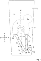
- the embodiment shown of a knee-joint bandage according to the invention comprises a tubular base body 1 made of an elastic textile material, for example an elastic knitted fabric, in particular a compression knitted fabric, which has a compression-giving, elastic weft thread.
- the base body 1 has an outer side a and, when the bandage is applied to a knee joint G, the inner side i facing the knee joint G, as in FIG Figure 3 shown.
- the knee joint bandage further comprises a first pad 2 arranged on the base body 1 and in particular integrated in the base body 1 and a tension band 3 connected to the first pad 2.
- the first pad 2 is made of an elastic material, for example silicone or silicone rubber or a rubber material is at least substantially U-shaped or horseshoe-shaped.
- the tension band connected to the first pad 2 in a tensile manner is made of an inelastic material or of a material that is at least less elastic than the material of the first pad 2 and has a first end 3a and a second end 3b.
- the drawstring 3 is composed of a total of three sections 3 ', 3 "and 3'", with a first section 3 'and a second section 3 "each on the outside a of the base body 1 and a third section connecting the first and second sections Section 3 '"is arranged in the interior of the tubular base body 1, that is to say on its inside i.
- the base body 1 Two openings 11, in particular in the form of slots, through which the tension band 3 is guided, are provided in the base body 1 for introducing and removing the tension band 3 into and out of the interior of the tubular base body 1.
- the third section 3 ′′ ′′ of the tension band 3 running inside the tubular base body 1 runs within the first pad 2.
- the third section 3 ′′ ′′ of the tension cord 3 is expediently cast into the elastic material of the first pad 2 and is thus tensile with the first pad 2 connected.
- the inner, third section 3 '''of the The tension band 3 can, however, also be arranged outside the first pad 2 and be connected to it in a tensile manner, for example by gluing.
- FIG. 1 an in the inside i of the base body 1 is Figures 1 and 2 Pocket 10 shown in dashed lines is provided.
- the pocket 10 can, for example, be sewn on the inside i of the base body 1 and connected to the base body 1 in this way.
- the pocket 10 is connected to the openings 11 in the base body 1, so that the third section 3 '''of the drawstring 3 can be inserted into the pocket 10 through one of the two openings 11 on one side. and can be guided out of the pocket 10 on the other side through the other opening 11.
- the pocket 10 and the first pad 2 arranged therein can be seen to have a bulge 2a in the medial-proximal area.
- This bulge 2a serves to exert a stimulating effect on the muscles
- the arranged in the pocket 10 first pad 2 encompasses the in Figure 1 Dashed patella K in the proximal as well as in the medial and lateral area.
- the directions related to the knee joint G medial m, lateral 1, proximal p and distal d are indicated by arrows.
- the two outer sections 3 'and 3 "of the tension band 3 are fixed by means of fixing means 4.
- the embodiment shown is both the first section 3 ', which contains the first end 3a of the tension band 3, and the second section 3 ′′, which contains the second end 3b of the tension band 3, each deflected by an associated deflection means 4a, 4b by 180 °.
- both the first end 3a and the second end 3b of the tension band 3 are each arranged on fastening means 4c, 4d with which the 180 ° deflected section of the tension band 3 is fixed to the respective outer section 3 'or 3 ".
- the deflection means 4a, 4b can be, for example, deflection eyes or - as in the exemplary embodiments of FIG Figures 1 and 2 shown - act around deflection openings in a tab 16 fastened on the outside a of the base body 1.
- the position of the deflection means 4a, 4b defines an anchoring point for each of the two sections 3 'and 3 "of the tension band 3, at which the respective section 3' or 3" of the Tension band 3 is anchored in relation to the base body 1.
- the first deflection means 4a assigned to the first section 3 'of the tension band 3 defines a first anchoring point 5a
- the second deflection means 4b assigned to the second section 3 "defines a second anchoring point 5b Figure 1
- both the first anchoring point 5a and the second anchoring point 5b lie both distal and medial to the sagittal plane M, which passes through the center of the patella K and contains the central longitudinal axis of the patellar tendon P.
- the two anchoring points 5a, 5b are both medial and distal to the patellar tendon P.
- the position of the anchoring points together with the position of the openings 11 through which the outer sections 3 ', 3 "of the tension band 3 are guided to the outside, determines the position of the outer sections 3' and 3" in relation to the base body 1, the outer sections 3 'and 3 "each extending between the associated opening 11 and the first anchoring point 5a and the second anchoring point 5b, respectively.
- the directions of the tensile forces exerted by the two outer sections 3 'and 3 "of the tension band 3 on the first pad 2 result from the position of the two outer sections 3' and 3" of the tension band 3, which correspond to the embodiment of FIG Figure 1 can be found.
- the two outer sections 3 'and 3 "of the tension band 3 enclose an angle of approximately 45 ° with one another.
- the two anchoring points 5a, 5b, at which the tension band 3 is anchored on the outside a of the base body 1, are moved downward in the distal direction, as a result of which the two outer sections 3 ' and 3 ′′ of the tension band 3 exert a tensile force directed in the respective longitudinal direction of the first and the second section 3 ′, 3 ′′ on the first pad 2.
- a force in the distal direction is exerted on the first pad 2 by the second section 3 ′′ of the tension band 3 running in the distal-proximal direction. Due to the asymmetrical arrangement of the two anchoring points 5a, 5b in relation to the sagittal plane M or in relation to the Patellar tendon P and the associated inclination of the first section 3 'of the tension band 3 (as from Figure 1 (can be seen), a tensile force exerted by the first section 3 'of the tension band 3, which comprises a force component in the distal direction and a force component in the medial direction, also acts on the first pad 2.
- the tension band 3 acts on the first pad 2 with a force pointing in the distal and medial direction, whereby the patella K is centered in its physiologically correct position when the knee joint is moved, in particular when the knee is bent
- Tensile force transmitted by the tension band 3 to the first pad 2 acts in the distal and medial direction on the patella K, which is surrounded by the first pad 2 in its proximal and medial-lateral area.
- the tensile force exerted by the tension band 3 on the first pad 2 results in lateralization of the patella K on the one hand and suppresses the patella K from being pushed up in the proximal direction on the other hand.
- FIG. 3 This mechanism is shown in the sectional view of Figure 3 can be seen in which the use of the knee joint bandage in a first therapy phase is shown by a sectional view of the knee joint bandage in a state applied to a flexed knee joint.
- the knee joint bandage is applied to the knee joint G in such a way that the first pad 2 with the third section 3 '''of the tension band 3 running therein surrounds the patella K in its proximal, lateral and medial area.
- the knee-joint bandage comprises, in addition to the first pad 2, which is arranged on the inside i of the base body 1 in the pocket 10, a second pad 6, which is also attached to the inside i of the base body 1 and is arranged distal to the patella K. .
- the position of the second pad 6 in the area below the first pad 2 is shown in dashed lines.
- the second pad 6 is designed in the form of a band and, when the knee joint bandage is placed on the knee joint G, runs across the patellar tendon P, as shown in FIG Figure 3 evident.
- the fastening elements 8, 9 can for example be the elements of a Velcro fastener, in particular a hook part and an associated fleece part of a Velcro fastener.
- a fastening element 8 in the form of a hook part of a Velcro fastener is arranged, which cooperates with a corresponding fleece part on the inside i of the base body 1, around the band-shaped second pad 6 detachable on the inside i of the base body 1 to be attached.
- the second pad 6 on the off Figure 3 apparent position on the inside i of the base body 1, the second pad 6 exerts a pressure on the patellar tendon P and thus puts it under tension when the knee joint moves. This relieves the strain on the tendons, bone attachments and cartilage structures in the knee joint.
- the second pad 6 has a stabilizing and relieving effect on the knee joint and counteracts movement restrictions in the event of degeneration of the knee joint.
- the patella K is pushed up in the proximal direction, which can be caused by the pressure exerted by the second pad 6 on the patellar tendon P, through which the patella K is located proximally and this prevents the first pad 2 surrounding it in the proximal and in the medial-lateral area.
- the patella K is centered in its physiologically correct position when the knee joint bandage is on, without the patella K being pushed up in the proximal direction (upward) or drifting in the lateral direction (outward).
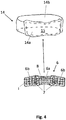
- the second pad 6, shown in detail below is at least essentially in the form of a band and has a longitudinal side which extends across the patellar tendon P when the knee joint bandage is put on, when the second pad 6, as in FIG Figure 3 shown, is attached to the inside i of the base body 1.
- the second pad 6 expediently has a middle section 6a and two laterally adjoining edge-side sections 6b, the edge-side sections 6b being bent downwards from the middle section 6a, ie, in the distal direction, as shown in FIG Figure 4 shown below.
- cranked is understood to mean that the edge-side sections 6b are at an angle extend at an angle in the range from 10 ° to 30 ° to the central section 6a.
- the distally cranked edge-side sections 6b enable a better fit and conformability over the Hoffa's fat body.
- the inside of the second pad 6 facing the knee joint when the knee bandage is applied has a plurality of stimulation elements 7, in particular in the form of elevations or projections and preferably in the form of knobs.
- the second pad 6 shown below can also be used in a separate second therapy phase without the base body 1 with the first pad 2 integrated therein.
- An in Figure 4 The retaining strap 14 shown above is provided, which has a receiving section 14a to which the second pad 6 can be detachably attached.
- the receiving section 14a expediently has detachable fastening means 15, in particular part of a Velcro fastener, with which the second pad 6 can be fastened to the receiving section 14a of the retaining strap 14.
- the fastening means 15 on the receiving section 14a of the retaining strap 14 are expediently designed as a corresponding fleece part of a Velcro fastener.
- the retaining strap 14 has a retaining portion 14b connected to the receiving portion 14a, the retaining portion 14b preferably being designed as a length-adjustable strap or as an elastic band, for example as a rubber band.
- the holding strap 14 with the second pad 6 attached to the receiving section 14a can be placed on the knee joint G, as in FIG Figure 5 shown.
- the retaining strap 14 runs in the area below the hollow of the knee and extends over the circumference of the upper section of the lower leg, the second pad 6 attached to the inside of the receiving section 14a of the retaining strap 14 lying in the area of the patellar tendon P and extending across the patellar tendon P. extends.
- the second pad 6 exerts pressure on the patellar tendon P, in particular when the knee joint G moves.
- the patellar tendon P and the tissue surrounding it are stimulated by the stimulation elements 7, as a result of which the blood flow to the body tissue is improved.
- the knee joint support according to the invention can thus on the one hand in the in Figure 3 and on the other hand in the manner shown in Figure 5 can be used for the therapy of knee joint complaints in the manner shown, whereby in the in Figure 3 first use form shown both the first pad 2 and the second pad 6 exerts a pressure on certain areas of the knee joint G and in the in Figure 5 The second form of use shown, a pressure is exerted on the patellar tendon P only by the second pad 6.
- the knee joint bandage according to the invention can therefore be used to treat various knee problems, such as damage to the knee joint in the sliding bearing between the patella and thigh, a high patella, femoropatellar pain syndrome, patella dislocations or subluxations, Osgood Schlatter's disease, gonar arthrosis or Joint effusions and irritation in the knee joint can be used for therapy on the one hand and also preventively on the other.
- a combined therapy with a use of the knee joint support according to the invention in the in Figure 3 The form of use shown in a first therapy phase and then in a second therapy phase in the in Figure 5 the form of use shown should be expedient.
- the bandage can, for example, be used with a second pad 6 attached to the inside for a therapy duration of 10 to 100 days in order to alleviate the symptoms of knee joint defects and to eliminate the cause.
- This first therapy phase can be followed by the second therapy phase, in which the second pad 6, together with the associated retaining strap 14, is used as a patellar tendon bandage Figure 3 is clearly placed on the knee joint.
- the second therapy phase can also be a preventive phase in which the patellar tendon bandage is used, for example, for prevention only while the patient is exercising.
- the deflection of the two outer sections 3 ', 3 "of the tension strap 3 can be dispensed with.
- the deflection means 4a, 4b used to deflect the sections 3', 3" of the tension strap 3 can also be fastened directly to the outside a of the base body 1 without deflection by means of the fastening means 4c, 4c arranged at the ends 3a, 3b.
- the anchoring points 5a, 5b of the tension band 3 are determined by the position of the fastening means 4c, 4d, by means of which the ends 3a, 3b of the tension band 3 are attached to the base body 1.
- the point at which the sections 3 ′, 3 ′′ of the tension band 3 are anchored or fixed on the base body 1 is decisive for the definition of the two anchoring points 5a, 5b.
- both the first pad 2 and the second pad 6 can be shaped differently.
- further bulges or additional stimulation elements can be provided on the first pad 2, which in particular contribute to interplanetary stimulation of the knee joint G.
- one of the two anchoring points can lie distal to the patella K and also lie in the line of the extension of the patellar tendon P in its longitudinal direction on the tibia S.
Abstract
Die Erfindung betrifft eine Bandage für ein Kniegelenk (K), umfassend einen schlauchförmigen Grundkörper (1) aus einem elastischen Textilmaterial mit einer bei am Kniegelenk (G) angelegter Bandage dem Kniegelenk zugewandten Innenseite (i), zumindest eine am Grundkörper angeordnete erste Pelotte (2), welche bei angelegter Bandage proximal zur Kniescheibe positioniert ist und die Kniescheibe zumindest teilweise umgreift, sowie eine distal zur ersten Pelotte angeordnete zweite Pelotte (6), welche bei angelegter Bandage über die Patellasehne (P) verläuft. Die zweite Pelotte ist dabei abnehmbar an der Innenseite des Grundkörpers befestigt. Dadurch kann die Bandage für unterschiedliche Therapiephasen sowohl mit als auch ohne die zweite Pelotte verwendet werden und die zweite Pelotte kann auch separat in einer Patellasehnenbandage eingesetzt werden.The invention relates to a bandage for a knee joint (K), comprising a tubular base body (1) made of an elastic textile material with an inside (i) facing the knee joint when the bandage is placed on the knee joint (G), at least one first pad (2) arranged on the base body ), which is positioned proximal to the kneecap when the bandage is applied and at least partially encompasses the kneecap, as well as a second pad (6) which is arranged distal to the first pad and which extends over the patellar tendon (P) when the bandage is applied. The second pad is detachably attached to the inside of the base body. As a result, the bandage can be used for different therapy phases both with and without the second pad and the second pad can also be used separately in a patellar tendon bandage.
Description
Die Erfindung betrifft eine Kniegelenkbandage nach dem Oberbegriff des Anspruchs 1.The invention relates to a knee joint bandage according to the preamble of
Aus dem Stand der Technik sind Orthesen in Form von textilen Bandagen zur Korrektur und/oder Entlastung des Kniegelenks und insbesondere zur Beeinflussung des Patellagleitwegs bekannt. Diese Orthesen umfassen einen schlauchförmigen Grundkörper aus einem Textilmaterial und weisen mindestens eine, lokal um die Patella angeordnete Druckpelotte aus einem flexiblen Material, beispielsweise aus Silikon, auf. Die wenigstens eine Pelotte gibt der Patella bei Bewegungen des Kniegelenks eine Führung und kann dadurch bei Schädigung des Kniegelenks im Gleitlager zwischen der Patella und dem Oberschenkel zu einer Schmerzreduktion beitragen. Durch einstellbare Zug- oder Druckelemente, wie z.B. Zugbänder, die mit der Pelotte zugfest verbunden sind, soll eine positive Beeinflussung des Patellagleitwegs bei einer Bewegung des Kniegelenks in einer physiologisch günstigen Position erreicht werden.Orthoses in the form of textile bandages for correcting and / or relieving the knee joint and in particular for influencing the patellar glide path are known from the prior art. These orthotics comprise a tubular base body made of a textile material and have at least one pressure pad made of a flexible material, for example made of silicone, which is arranged locally around the patella. The at least one pad guides the patella when the knee joint moves and can thereby contribute to a pain reduction in the case of damage to the knee joint in the sliding bearing between the patella and the thigh. Adjustable tension or pressure elements, such as tension straps, which are connected to the pad in a tensile manner, should have a positive influence on the patellar glide path when the knee joint moves in a physiologically favorable position.
Weiterhin sind Patellasehnenbandagen bekannt, welche eine quer über die Patellasehne verlaufenden Pelotte aufweisen, die zu einer Vorspannung der Patellasehne sowie zu einer Stabilisierung des Kniegelenks und dadurch zu einer Schmerzlinderung beiträgt. Eine solche Patellasehnenbandage ist bspw. aus der
Bei Verwendung solcher Patellasehnenbandagen kann es bei einer Bewegung des Kniegelenks zu einem Hochschieben der Patella in eine physiologisch ungünstige Position kommen.When using such patellar tendon bandages, movement of the knee joint can push the patella up into a physiologically unfavorable position.
Um dies zu verhindern schlägt die
Hiervon ausgehend besteht ein Bedürfnis für eine Kniegelenkbandage, die einerseits eine aktive Stabilisierung der Patella, insbesondere in lateraler Richtung, bewirkt und andererseits einem Hochschieben der Patella bei einer Bewegung des Kniegelenks entgegenwirkt und darüber hinaus in möglichst flexibler Weise und in unterschiedlichen Therapieformen und -stufen einen gezielten Druck auf die Patellasehne ausüben kann, um Patellasehnenreizungen zu lindern.Based on this, there is a need for a knee joint bandage which, on the one hand, brings about an active stabilization of the patella, especially in the lateral direction, and, on the other hand, counteracts the patella being pushed up when the knee joint moves, and also in the most flexible way possible and in different forms and stages of therapy Apply targeted pressure on the patellar tendon to relieve patellar tendon irritation.
Der Erfindung liegt daher die Aufgabe zugrunde, eine Kniegelenkbandage bereit zu stellen, die bei einer Therapie von Kniegelenksbeschwerden eine optimierte Bewegungsführung des Kniegelenks ermöglicht und insbesondere einerseits ein Abdriften der Patella nach außen (also in lateraler Richtung) und andererseits ein Hochschieben der Patella in proximaler Richtung unterdrückt und gleichzeitig durch gezielten Druck auf die Patellasehne Patellasehnenreizungen lindern kann. Dabei soll die Kniegelenkbandage eine Therapie von unterschiedlichen Kniegelenksbeschwerden in möglichst flexibler Weise, insbesondere in unterschiedlichen Therapiestufen, das Kniegelenk bei einer Bewegung in einer physiologisch optimierten Position halten und dabei eine individuelle Anpassung an die Anatomie eines Patienten ermöglichen. Weiterhin soll durch die Kniegelenkbandage eine Durchblutung des das Kniegelenk umgebenden Gewebes gefördert, Schwellungen und Ergüsse abgebaut sowie Reizungen und Schmerzen gelindert werden.The invention is therefore based on the object of providing a knee joint bandage which, in the treatment of knee joint complaints, enables optimized movement control of the knee joint and, in particular, on the one hand, the patella drifting outwards (i.e. in the lateral direction) and, on the other hand, the patella being pushed up in the proximal direction suppresses and at the same time relieves patellar tendon irritation by applying targeted pressure to the patellar tendon. The knee joint bandage is intended to provide therapy for different knee joint complaints in the most flexible way possible, in particular in different therapy stages, to keep the knee joint in a physiologically optimized position during movement and thereby enable individual adaptation to the anatomy of a patient. Furthermore, the knee joint bandage is intended to provide blood flow to the knee joint surrounding tissue is promoted, swellings and effusions are reduced, and irritation and pain are relieved.
Diese Aufgaben werden mit einer Kniegelenkbandage mit den Merkmalen des Anspruchs 1 sowie mit einem Bandagenset nach Anspruch 11 gelöst. Bevorzugte Ausführungsformen dieser Kniegelenkbandage und des Bandagensets sind den abhängigen Ansprüchen zu entnehmen.These objects are achieved with a knee joint bandage with the features of
Die Kniegelenkbandage gemäß der Erfindung umfasst einen schlauchförmigen Grundkörper aus einem elastischen Textilmaterial mit einer bei am Kniegelenk angelegter Bandage dem Kniegelenk zugewandten Innenseite, zumindest eine am Grundkörper angeordnete erste Pelotte, welche bei angelegter Bandage proximal zur Patella positioniert ist und die Patella zumindest teilweise umgreift, sowie eine distal zur ersten Pelotte angeordnete zweite Pelotte, welche bei angelegter Bandage über die Patellasehne verläuft, wobei die zweite Pelotte abnehmbar an der Innenseite des Grundkörpers befestigt ist.The knee joint bandage according to the invention comprises a tubular base body made of an elastic textile material with an inside facing the knee joint when the bandage is applied to the knee joint, at least one first pad arranged on the base body, which is positioned proximal to the patella when the bandage is applied and at least partially encompasses the patella, as well as a second pad which is arranged distally to the first pad and which, when the bandage is applied, runs over the patellar tendon, the second pad being removably attached to the inside of the base body.
Dadurch kann die Kniegelenkbandage gemäß der Erfindung in flexibler Weise sowohl mit als auch ohne die zweite Pelotte eingesetzt werden, indem die zweite Pelotte entweder mittels lösbarer Befestigungsmittel an der Innenseite des Grundkörpers befestigt und die Bandage in dieser Form an ein zu therapierendes Kniegelenk angelegt wird, oder indem die zweite Pelotte durch Lösen der Befestigungsmittel von dem Grundkörper abgenommen und dieser nur mit der zweckmäßig darin integrierten ersten Pelotte an ein Kniegelenk angelegt wird. Weiterhin kann die vom Grundkörper abgenommene zweite Pelotte auch in Verbindung mit einem zugehörigen Halteband als Patellasehnenbandage ohne den Grundkörper und die darin integrierte erste Pelotte, eingesetzt werden, indem die vom Grundkörper abgenommene zweite Pelotte mittles lösbarer Befestigungsmittel an ein Halteband befestigt und mit diesem Halteband an einem Kniegelenk unterhalb der Patella angelegt wird.As a result, the knee joint bandage according to the invention can be used in a flexible manner both with and without the second pad, in that the second pad is either fastened to the inside of the base body by means of releasable fastening means and the bandage is applied in this form to a knee joint to be treated, or in that the second pad is removed from the base body by loosening the fastening means and this is only applied to a knee joint with the first pad which is expediently integrated therein. Furthermore, the second pad removed from the base body can also be used in conjunction with an associated retaining strap as a patellar tendon bandage without the base body and the first pad integrated therein Knee joint is placed below the patella.
Die zweite Pelotte übt sowohl in der Funktionsstellung bei angelegter Kniegelenkbandage mit an der Innenseite des Grundkörpers befestigter zweiter Pelotte als auch bei Anlegung der zweiten Pelotte am Kniegelenk mit dem Halteband als Patellasehnenbandage jeweils einen dosierten Druck auf die Patellasehne aus, insbesondere an ihrem Ansatz, und kann dadurch die Patellasehne entlasten. Weiterhin führt die zweite Pelotte zu einer Vorspannung der Patellasehne, wodurch bei einer Bewegung des Kniegelenks eine weitere Stabilisierung erfolgt.The second pad exerts a measured pressure on the patellar tendon, in particular at its attachment, both in the functional position when the knee joint bandage is applied and the second pad is attached to the inside of the base body, and when the second pad is applied to the knee joint with the retaining band as a patellar tendon bandage thereby relieve the patellar tendon. Furthermore, the second pad leads to a pretensioning of the patellar tendon, which results in further stabilization when the knee joint moves.
Durch die zweite Pelotte können daher Patellasehnenreizungen therapiert und dadurch hervorgerufene Schmerzen gelindert werden.The second pad can therefore treat irritation of the patella tendon and relieve the pain caused by it.
Bevorzugt ist die zweite Pelotte mittles lösbarer Befestigungsmittel, wie z.B. Klettverschlüsse, abnehmbar an der dem Kniegelenk zugewandten Innenseite des Grundkörpers befestigbar. Durch die lösbare Anordnung der zweiten Pelotte an der Innenseite des Grundkörpers der Kniegelenkbandage kann diese in unterschiedlichen Therapiephasen bei der Therapie von Kniegelenkbeschwerden eingesetzt werden. Insbesondere kann in einer ersten Therapiephase eine Therapie des Kniegelenks sowohl mit der ersten als auch mit der zweiten Pelotte erfolgen, indem die zweite Pelotte an der Innenseite des Grundkörpers befestigt und die Kniegelenkbandage in diesem Zustand an einem Kniegelenk angelegt wird. In dieser ersten Therapiephase verhindert die erste Pelotte in Verbindung mit dem an den Verankerungspunkten verankerten Zugband ein Hochschieben der Patella durch die distal der Patella angelegte und quer über die Patellasehne verlaufende zweite Pelotte bei einer Bewegung des Kniegelenks, insbesondere bei einer Beugung des Knies.The second pad can preferably be detachably fastened to the inside of the base body facing the knee joint by means of detachable fastening means, such as Velcro fasteners. Due to the detachable arrangement of the second pad on the inside of the base body of the knee joint bandage, it can be used in different therapy phases in the therapy of knee joint complaints. In particular, in a first therapy phase, the knee joint can be treated with both the first and the second pad by attaching the second pad to the inside of the base body and applying the knee joint bandage to a knee joint in this state. In this first therapy phase, the first pad, in conjunction with the tension band anchored at the anchoring points, prevents the patella from being pushed up by the second pad, which is placed distal to the patella and runs across the patellar tendon, when the knee joint moves, in particular when the knee is bent.
In einer zweiten Therapiephase kann die zweite Pelotte von der Kniegelenkbandage gelöst und in Verbindung mit dem Halteband am Kniegelenk unterhalb (also distal) der Patella angeordnet werden. In dieser zweiten Therapiephase wirkt die zweite Pelotte zusammen mit dem Halteband als Patellasehnenbandage, welche einen Druck auf die Patellesehne ausübt und dadurch zu einer Vorspannung der Patellasehne führt, wodurch Patellasehnenschmerzen verringert werden können. Die zweite Therapiephase kann dabei auch eine präventive Therapiephase sein, die nach einer erfolgreichen ersten Therapiephase erfolgt, um ein Wiederauftreten der Kniegelenkbeschwerden zu verhindern. Insbesondere kann die zweite Therapiephase bei sportlicher Betätigung des Patienten erfolgen, um dabei das Kniegelenk zu stabilisieren und zu entlasten, wodurch Verletzungen oder Überbeanspruchungen verhindert werden können.
Um sowohl die erste als auch die zweite Therapiephase durchführen zu können, ist ein Bandagenset vorteilhaft, das eine erfindungsgemäße Bandage und ein Halteband umfasst, an dem die zweite Pelotte, insbesondere über einen Klettverschluss, lösbar befestigt werden kann. Ein solches Bandagenset ermöglicht es, die zweite Pelotte entweder zusammen mit der Kniegelenkbandage oder auch einzeln als Patellasehnenbandage (unabhängig von der Kniegelenkbandage) zu verwenden, indem die zweite Pelotte mit dem Halteband am Knie eines Patienten angelegt wird. Gegenstand der Erfindung ist daher auch ein Bandagenset, das eine Bandage sowie ein Halteband enthält, wobei die Bandage einen schlauchförmigen Grundkörper aus einem elastischen Textilmaterial mit einer Innenseite, zumindest eine am Grundkörper angeordnete erste Pelotte, welche bei angelegter Bandage proximal zur Patella positioniert ist und die Patella zumindest teilweise umgreift, sowie eine distal zur ersten Pelotte anordenbare zweite Pelotte, welche bei angelegter Bandage über die Patellasehne verläuft, umfasst, wobei die zweite Pelotte abnehmbar an der Innenseite des Grundkörpers befestigbar ist und auch an dem Halteband lösbar befestigbar ist.In a second therapy phase, the second pad can be detached from the knee joint bandage and, in conjunction with the retaining strap, placed on the knee joint below (that is, distally) the patella. In this second phase of therapy, the second pad, together with the tether, acts as a patellar tendon bandage, which exerts pressure on the patellar tendon and thereby leads to a pretensioning of the patellar tendon, which can reduce patellar tendon pain. The second therapy phase can also be a preventive therapy phase, which takes place after a successful first therapy phase in order to prevent the knee joint complaints from recurring. In particular, the second therapy phase can take place when the patient is exercising, in order to stabilize and relieve the knee joint, whereby injuries or excessive strain can be prevented.
In order to be able to carry out both the first and the second therapy phase, a bandage set is advantageous which comprises a bandage according to the invention and a retaining strap to which the second pad can be releasably attached, in particular via a Velcro fastener. Such a bandage set makes it possible to use the second pad either together with the knee joint bandage or individually as a patellar tendon bandage (independent of the knee joint bandage) by applying the second pad with the retaining strap to a patient's knee. The invention therefore also relates to a bandage set which contains a bandage and a retaining strap, the bandage having a tubular base body Made of an elastic textile material with an inside, at least one first pad arranged on the base body, which is positioned proximal to the patella when the bandage is applied and at least partially encompasses the patella, and a second pad which can be arranged distal to the first pad and runs over the patellar tendon when the bandage is applied , wherein the second pad is removably attachable to the inside of the base body and is also releasably attachable to the retaining strap.
In einer bevorzugten Ausführungsform der erfindungsgemäßen Kniegelenkbandage ist die erste Pelotte in dem schlauchförmigen Grundkörper integriert und insbesondere in einer Tasche angeordnet. Dadurch ist eine sichere und positionsgerechte Anordnung der ersten Pelotte um die Patella beim Anlegen der Kniegelenkbandage gewährleistet. Die Tasche ist bevorzugt an der Innenseite des Grundkörpers befestigt, beispielsweise durch Vernähen oder Verstricken mit dem Grundkörper.In a preferred embodiment of the knee joint bandage according to the invention, the first pad is integrated in the tubular base body and, in particular, is arranged in a pocket. This ensures that the first pad is arranged in the correct position around the patella when the knee joint bandage is applied. The pocket is preferably attached to the inside of the base body, for example by sewing or knitting with the base body.
In einer bevorzugten Ausführungsform ist mit der ersten Pelotte ein Zugband verbunden, wobei das Zugband ein erstes und ein zweites Ende aufweist, und des Zugband nahe oder an seinen beiden Enden distal der Patella am Grundkörper mittels lösbarer Fixiermittel an vorgegebenen Verankerungspunkten verankerbar ist. Dabei umgreift die bevorzugt U- oder hufeisenförmig ausgebildete erste Pelotte bei an einem Kniegelenk angelegter Kniegelenkbandage die Patella zumindest teilweise in ihrem proximalen Bereich und bevorzugt auch seitlich, d.h. in ihrem medialen und lateralen Bereich. Bei einer Bewegung des Kniegelenks wird dabei auf die Patella aktiv eine stabilisierende und die Patella zentrierende Kraft sowohl in medialer als auch in distaler Richtung augeübt. Das erste Ende des Zugbands ist dabei zweckmäßig an einem vorgegebenen ersten Verankerungspunkt und das zweite Ende des Zugbands an einem vorgegebenen zweiten Verankerungspunkt am Grundkörper der Bandage verankerbar, wobei bei angelegter Bandage beide Verankerungspunkte jeweils distal der Patella liegen und bevorzugt gleichzeitig entweder beide Verankerungspunkte medial zur Patellasehne liegen oder einer der beiden Verankerungspunkte medial zur Patellasehne und der andere Verankerungspunkt distal zur Patellasehne in der Linie der Verlängerung der Patellasehne in Längsrichtung auf dem Schienbein liegt.In a preferred embodiment, a tension band is connected to the first pad, the tension band having a first and a second end, and the tension band can be anchored near or at its two ends distal to the patella on the base body by means of detachable fixing means at predetermined anchoring points. The first pad, which is preferably U-shaped or horseshoe-shaped, surrounds the patella at least partially in its proximal area and preferably also laterally, i.e. in its medial and lateral area, when the knee joint bandage is applied to a knee joint. When the knee joint moves, a stabilizing force that centers the patella is actively exerted on the patella, both in the medial and in the distal direction. The first end of the tension band can expediently be anchored at a given first anchoring point and the second end of the tension band can be anchored at a given second anchoring point on the base body of the bandage, with both anchoring points each distal to the patella and preferably at the same time either both anchoring points medial to the patellar tendon or one of the two anchoring points is medial to the patellar tendon and the other anchoring point is distal to the patellar tendon in the line of the longitudinal extension of the patellar tendon on the tibia.
Dadurch liegen die Verankerungspunkte der beiden Enden des Zugbands einerseits distal der Patella und andererseits entweder beide medial zur Patellasehne oder es liegt einer der beiden Verankerungspunkte medial zur Patellasehne während der andere Verankerungspunkt distal zur Patellasehne in der Linie der Verlängerung der Patellasehne in Längsrichtung auf dem Schienbein liegt. In Bezug auf eine durch das Kniegelenk verlaufende Sagittalebene liegen die beiden Verankerungspunkte der beiden Enden des Zugbands bei dieser Ausführungsform der Erfindung nicht symmetrisch um die Sagittalebene, sondern es liegen entweder beide Verankerungspunkte distal dieser Sagittalebene oder es liegt nur einer der beiden Verankerungspunkte medial zur Sagittalebene und der andere Verankerungspunkt liegt distal zur Patellasehne in dieser Sagittalebene, die durch die Verlängerung der Patellasehne in deren Längsrichtung auf dem Schienbein definiert ist.As a result, the anchoring points of the two ends of the tension band are on the one hand distal to the patella and on the other hand either both medial to the patellar tendon or one of the two is located Anchoring points medial to the patellar tendon while the other anchoring point lies distal to the patellar tendon in the line of the extension of the patellar tendon in the longitudinal direction on the tibia. In relation to a sagittal plane running through the knee joint, the two anchoring points of the two ends of the tension band in this embodiment of the invention are not symmetrical about the sagittal plane, but rather either both anchoring points are distal to this sagittal plane or only one of the two anchoring points is medial to the sagittal plane and the other anchoring point is distal to the patellar tendon in this sagittal plane, which is defined by the extension of the patellar tendon in its longitudinal direction on the tibia.
Durch diese Anordnung der Verankerungspunkte, an denen die beiden Enden des Zugbands am Grundkörper der Kniegelenkbandage verankert werden, wird bei dieser bevorzugten Ausführungsform der erfindungsgemäßen Kniegelenkbandage bei einer Bewegung des Kniegelenks, insbesondere beim Beugen des Knies, durch die erste Pelotte, die zugfest mit dem Zugband verbunden ist, aktiv eine Kraft auf die Patella ausgeübt, die einerseits in medialer und andererseits in distaler Richtung auf die Patella einwirkt und dadurch verhindert, dass die Patella nach außen oder nach oben in eine physiologisch ungünstige Stellung verschoben wird. Diese Ausführungsform der Kniegelenkbandage bewirkt daher einerseits eine Lateralisierung der Patella und wirkt andererseits einem Hochschieben der Patella oder einem Patellahochstand entgegen.With this arrangement of the anchoring points at which the two ends of the tension band are anchored to the base body of the knee joint bandage, in this preferred embodiment of the knee joint bandage according to the invention, when the knee joint is moved, in particular when the knee is bent, the first pad, which is tension-proof with the tension band is connected, actively exerts a force on the patella, which acts on the one hand in the medial and on the other hand in the distal direction on the patella and thereby prevents the patella from being displaced outwards or upwards into a physiologically unfavorable position. This embodiment of the knee joint bandage therefore on the one hand causes the patella to be lateralized and on the other hand counteracts the patella being pushed up or raised.
Dieser Effekt wird dabei durch ein Zusammenwirken der aus einem elastischen Material, wie z.B. Silikon, gefertigten ersten Pelotte und der zugfest mit dieser Pelotte verbundenen Zugband sowie dessen Verankerung an den definierten Verankerungspunkten (erster und zweiter Verankerungspunkt) bewirkt.This effect is brought about by the interaction of the first pad, made of an elastic material such as silicone, and the tension band connected to this pad with tensile strength, as well as its anchoring at the defined anchoring points (first and second anchoring point).
Das Zugband ist dabei zweckmäßig unelastisch oder zumindest deutlich weniger elastisch als das Material der ersten Pelotte. Das Zugband kann entweder durchgehend vom ersten Ende zum zweiten Ende ausgebildet sein und abschnittsweise zugfest mit der ersten Pelotte verbunden sein. Insbesondere kann das durchgehend ausgebildete Zugband im Bereich der ersten Pelotte durch das elastische Material der ersten Pelotte durchlaufen und dabei mit der ersten Pelotte verbunden sein, indem das Zugband in das elastische Material der ersten Pelotte, bei dem es sich beispielsweise um Silikon oder Silikonkautschuk handeln kann, eingegossen ist. Das Zugband kann jedoch auch abschnittsweise an Unterbrechungsstellen unterbrochen sein, wobei das abschnittsweise unterbrochene Zugband an den Unterbrechungsstellen mit der ersten Pelotte zugfest verbunden ist, indem das Zugband an den Unterbrechungsstellen beispielsweise mit dem elastischen Material der ersten Pelotte verklebt ist.The drawstring is expediently inelastic or at least significantly less elastic than the material of the first pad. The tension band can either be formed continuously from the first end to the second end and can be connected to the first pad in a tension-proof manner in sections. In particular, the continuous tension band in the area of the first pad can pass through the elastic material of the first pad and be connected to the first pad by inserting the tension band into the elastic material of the first pad, which can be silicone or silicone rubber, for example , is poured. However, the drawstring can also be interrupted in sections at interruption points The partially interrupted tension band is connected to the first pad with a tensile strength at the points of interruption, in that the tension band is glued, for example, to the elastic material of the first pad at the points of interruption.
In einem bevorzugten Ausführungsbeispiel der Erfindung sind die Enden des Zugbands mittels Fixiermittel an der Außenseite des Grundkörpers verankerbar. Zweckmäßig umfassen die Fixiermittel dabei lösbare Befestigungsmittel, wie z.B. Klettverschlüsse, wobei bevorzugt an jedem Ende des Zugbands ein solches Befestigungsmittel angeordnet ist, mit dem das jeweiligen Ende des Zugbands lösbar an der Außenseite des Grundkörpers befestigt werden kann. Wenn die (freien) Enden des Zugbands mittels der Befestigungsmittel an der Außenseite des Grundkörpers befestigt sind, sind die beiden Verankerungspunkte, also der erste Verankerungspunkt des ersten Endes und der zweite Verankerungspunkt des zweiten Endes, durch die Position der Befestigungsmittel definiert, über welche das jeweilige Ende des Zugbands an der Außenseite des Grundkörpers befestigt ist.In a preferred exemplary embodiment of the invention, the ends of the tension band can be anchored to the outside of the base body by means of fixing means. The fixing means expediently comprise detachable fastening means, such as Velcro fasteners, with such a fastening means preferably being arranged at each end of the tension band with which the respective end of the tension band can be releasably attached to the outside of the base body. If the (free) ends of the tension band are fastened to the outside of the base body by means of the fastening means, the two anchoring points, i.e. the first anchoring point of the first end and the second anchoring point of the second end, are defined by the position of the fastening means via which the respective The end of the drawstring is attached to the outside of the base body.
In einer weiteren Ausführungsform der Erfindung umfassen die Fixiermittel für jedes Ende des Zugbands Umlenkmittel, welche das Zugband nahe des jeweiligen Endes umlenken. Wie bei dem obigen Ausführungsbeispiel sind auch bei diesem Ausführungsbeispiel an jedem Ende des Zugbands Befestigungsmittel angeordnet, mit dem das jeweilige Ende des Zugbands lösbar an einem Abschnitt des Zugbands befestigbar ist. Dieses Ausführungsbeispiel ermöglicht die Ausübung höherer Zugkräfte aufgrund eines durch die Umlenkung des Zugbands an seinen Enden bewirkten Flaschenzugeffekts. Bei diesem Ausführungsbeispiel sind die beiden Verankerungspunkte, also der erste Verankerungspunkt des ersten Endes des Zugbands und der zweite Verankerungspunkt des zweiten Endes des Zugbands, durch die Stellen definiert, an denen das Zugband im Bereich des ersten Endes und im Bereich des zweiten Endes durch die Umlenkmittel umgelenkt wird. Die Position der Umlenkmittel, bei denen es sich beispielsweise um Umlenkösen oder -öffnungen in einer Umlenklasche handeln kann, definiert dabei die beiden Verankerungspunkte.In a further embodiment of the invention, the fixing means for each end of the tension band comprise deflection means which deflect the tension band near the respective end. As in the above exemplary embodiment, fastening means are also arranged in this exemplary embodiment at each end of the tension band, with which the respective end of the tension band can be releasably fastened to a section of the tension band. This exemplary embodiment enables higher tensile forces to be exerted due to a pulley effect caused by the deflection of the tension band at its ends. In this embodiment, the two anchoring points, i.e. the first anchoring point of the first end of the tension band and the second anchoring point of the second end of the tension band, are defined by the points at which the tension band in the area of the first end and in the area of the second end through the deflection means is diverted. The position of the deflection means, which can be, for example, deflection eyes or openings in a deflection strap, defines the two anchoring points.
Die vom Zugband auf die erste Pelotte bei einer Bewegung des Kniegelenks aktiv ausgeübte Kraft kann dabei durch die Positionen bestimmt werden, an denen die beiden Enden des Zugbands entweder an der Außenseite des Grundkörpers oder - bei umgelegten Bandabschnitten - auf einem Abschnitt des jeweiligen Bands mittels der Befestigungsmittel befestigt werden. Dadurch können unterschiedlich hohe Kräfte ausgeübt werden, je nach Position der fixierten Enden des Zugbands. Die ausgewählte Zugkraft kann dabei je nach Art oder Ziel der Therapie oder dem Grad der zu therapierenden Beschwerden angepasst werden. Die Richtung der ausgeübten Kräfte wird durch die Lage des Zugbands, insbesondere der äußeren Abschnitte des Zugbands, bestimmt.The force actively exerted by the drawstring on the first pad when the knee joint moves can be determined by the positions at which the two ends of the drawstring are either on the outside of the main body or - in the case of folded strap sections - on a section of the respective strap by means of the Fasteners are attached. This means that different forces can be exerted, depending on the Position of the fixed ends of the drawstring. The selected tensile force can be adjusted depending on the type or goal of the therapy or the degree of the complaints to be treated. The direction of the exerted forces is determined by the position of the tension band, in particular the outer sections of the tension band.
Im Bereich der Tasche, in der die erste Pelotte in einem bevorzugten Ausführungsbeispiel der Erfindung angeordnet ist, sind zweckmäßig zwei Öffnungen in dem Grundkörper vorgesehen. Die Öffnungen können insbesondere als schmale Schlitze ausgebildet sein, die sich in lateral-medialer Richtung (also etwa horizontal) erstrecken und/oder schräg zur lateral-medialer Richtung verlaufen können.In the area of the pocket in which the first pad is arranged in a preferred exemplary embodiment of the invention, two openings are expediently provided in the base body. The openings can in particular be designed as narrow slots which extend in the lateral-medial direction (that is to say approximately horizontally) and / or can run obliquely to the lateral-medial direction.
Das Zugband kann dabei aus mehreren Abschnitten zusammengesetzt sein und insbesondere einen ersten und einen zweiten Abschnitt umfassen, wobei der erste Abschnitt das erste Ende des Zugbands und der zweite Abschnitt das zweite Ende des Zugbands enthält und der erste und der zweite Abschnitt des Zugbands auf der Außenseite des schlauchförmigen Grundkörpers angeordnet sind. Der erste und der zweite Abschnitt des Zugbands sind dabei durch einen im Inneren des schlauchförmigen Grundkörpers und insbesondere durch die erste Pelotte verlaufenden dritten Abschnitt miteinander verbunden, so dass sich ein durchgehendes Zugband aus den drei Abschnitten zusammensetzt, welches bereichsweise innerhalb und bereichsweise außerhalb des schlauchförmigen Grundkörpers verläuft und durch die Öffnungen in dem Grundkörper von innen nach außen geführt ist. Der erste und der zweite Abschnitt des Zugbands liegt dadurch auf der Außenseite des schlauchförmigen Grundkörpers, weshalb der erste und der zweite Abschnitt im Folgenden auch als äußere Abschnitte bezeichnet werden.The drawstring can be composed of several sections and in particular comprise a first and a second section, the first section containing the first end of the drawstring and the second section containing the second end of the drawstring and the first and the second section of the drawstring on the outside of the tubular base body are arranged. The first and second sections of the tension band are connected to one another by a third section running inside the tubular base body and in particular through the first pad, so that a continuous tension band is composed of the three sections, which is partially inside and partially outside the tubular base body runs and is guided through the openings in the base body from the inside to the outside. As a result, the first and the second section of the tension band lie on the outside of the tubular base body, which is why the first and the second section are also referred to below as outer sections.
Die Position der Öffnungen, durch die die äußeren Abschnitte des Zugbands nach außen geführt sind, bestimmt dabei zusammen mit der Position der Verankerungspunkte die Lage der äußeren Abschnitte des Zugbands, die sich jeweils zwischen der zugeordneten Öffnung und dem jeweiligen Verankerungspunkt (erster bzw. zweiter Verankerungspunkt) erstrecken.The position of the openings through which the outer sections of the tension cord are led to the outside, together with the position of the anchoring points, determines the position of the outer sections of the tension cord, which are located between the associated opening and the respective anchoring point (first or second anchoring point ) extend.
Durch die gewählte Anordnung der Verankerungspunkte verläuft einer der beiden äußeren Abschnitte (zweiter Abschnitt) dabei zumindest im Wesentlichen in distal-proximaler Richtung, während der andere äußere Abschnitt (erster Abschnitt) schräg dazu verläuft, insbesondere von proximal-lateral nach distal-medial. In einer bevorzugten Ausführungsform schließen die beiden äußeren Abschnitte (erster und zweiter Abschnitt) des Zugbands einen Winkel im Bereich von 30° bis 60°, insbesondere von 45° ein. Durch diese Anordnung der beiden äußeren Abschnitte (erster und zweiter Abschnitt) des Zugbands erfolgt bei einer Bewegung des Knies eine Kraftausübung auf die Patella mit einer Kraftrichtung, die einerseits eine Komponente in distaler Richtung und andererseits eine Komponente in medialer Richtung aufweist.Due to the selected arrangement of the anchoring points, one of the two outer sections (second section) runs at least essentially in the distal-proximal direction, while the other outer section (first section) runs obliquely to it, in particular from proximal-lateral to distal-medial. In a preferred embodiment, the two outer sections (first and second section) of the tension band close one Angle in the range from 30 ° to 60 °, in particular from 45 °. Due to this arrangement of the two outer sections (first and second section) of the tension band, when the knee moves, a force is exerted on the patella with a force direction that has a component in the distal direction and a component in the medial direction.
Zur Erzielung eines Massageeffekts, der insbesondere eine durchblutungsfördernde Wirkung erzeugt, kann die erste Pelotte und die zweite über Stimulationselemente verfügen, z.B. in Form von Noppen oder Rippen, welche eine massierende Wirkung auf das die Patella und die Patellasehne umgebende Gewebe ausüben. Die erste Pelotte kann ferner eine im medial-proximalen Bereich angeordnete Ausbuchtung aufweisen, die eine stimulierende Wirkung auf die Muskulatur ausübt.To achieve a massage effect, which in particular produces an effect that stimulates blood circulation, the first pad and the second pad can have stimulation elements, e.g. in the form of knobs or ribs, which have a massaging effect on the tissue surrounding the patella and the patellar tendon. The first pad can also have a bulge arranged in the medial-proximal area, which has a stimulating effect on the muscles.
Das Textilmaterial des Grundkörpers ist elastisch ausgebildet. Insbesondere kann der Grundkörper aus einem elastischen Gestrick gebildet sein. Durch die Elastizität des schlauchförmigen Grundkörpers wird bei angelegter Kniegelenkbandage eine Kompression auf die das Kniegelenk umgebende Muskulatur ausgeübt, wodurch ein Massageeffekt und eine durchblutungsfördernde Wirkung erzeugt wird. Durch die von dem elastischen Textilmaterial des Grundkörpers ausgeübte Kompression werden weiterhin Schwellungen und Ergüsse im Bereich des Kniegelenks abgebaut.The textile material of the base body is elastic. In particular, the base body can be formed from an elastic knitted fabric. Due to the elasticity of the tubular base body, when the knee joint bandage is put on, compression is exerted on the muscles surrounding the knee joint, which produces a massage effect and a circulation-promoting effect. As a result of the compression exerted by the elastic textile material of the base body, swellings and effusions in the area of the knee joint are further reduced.
Diese und weitere Vorteile sowie Merkmale der Erfindung ergeben sich aus dem nachfolgend unter Bezugnahme auf die begleitenden Zeichnungen näher beschriebenen Ausführungsbeispiel, wobei die Zeichnungen zeigen:
- Fig. 1
- Vorderansicht auf eine Ausführungsform einer erfindungsgemäßen Kniegelenkbandage;
- Fig. 2
- perspektivische Ansicht auf die
Kniegelenkbandage von Figur 1 in einem an einem Kniegelenk angelegten Zustand; - Fig. 3
- Darstellung der Verwendung der
Kniegelenkbandage von Figur 1 in einer ersten Therapiephase durch eine Schnittdarstellung der Kniegelenkbandage in einem an einem gebeugten Kniegelenk angelegten Zustand; - Fig. 4
- Detailansicht der zweiten Pelotte der
Kniegelenkbandage von Figur 1 mit einem zugehörigen Halteband zur Ausbildung einer Patellasehnenbandage zum Anlegen der zweiten Pelotte an einem Kniegelenk; - Fig. 5
- Darstellung der Verwendung der
Patellasehnenbandage von Figur 4 in einer zweiten Therapiephase durch eine Schnittdarstellung der Patellasehnenbandage in einem an einem gebeugten Kniegelenk angelegten Zustand, wobei die zweite Pelotte mit dem zugehörigen Halteband am Kniegelenk unterhalb der Patella angelegt ist.
- Fig. 1
- Front view of an embodiment of a knee joint bandage according to the invention;
- Fig. 2
- perspective view of the knee brace from FIG
Figure 1 in a state applied to a knee joint; - Fig. 3
- Illustration of the use of the knee brace from
Figure 1 in a first therapy phase through a sectional view of the knee joint bandage in a state applied to a flexed knee joint; - Fig. 4
- Detailed view of the second pad of the knee brace from
Figure 1 with an associated retaining band for forming a patellar tendon bandage for applying the second pad to a knee joint; - Fig. 5
- Illustration of the use of the patellar tendon bandage from
Figure 4 in a second therapy phase by a sectional view of the patellar tendon bandage in a state applied to a flexed knee joint, the second pad with the associated retaining strap being applied to the knee joint below the patella.
Die in den
Zur Aufnahme der ersten Pelotte 2 und des darin verlaufenden dritten Abschnitts 3''' des Zugbands 3 ist an der Innenseite i des Grundkörpers 1 eine in den
Wie insbesondere aus der Vorderansicht der
Die beiden äußeren Abschnitte 3' und 3" des Zugbands 3 sind mittels Fixiermittel 4 festgelegt. Bei dem in den
Die Position der Umlenkmittel 4a, 4b definiert dabei für jeden der beiden Abschnitte 3' und 3" des Zugbands 3 einen Verankerungspunkt, an dem der jeweilige Abschnitt 3' bzw. 3" des Zugbands 3 in Bezug auf den Grundkörper 1 verankert ist. So definiert das dem ersten Abschnitt 3' des Zugbands 3 zugeordnete erste Umlenkmittel 4a einen ersten Verankerungspunkt 5a und das dem zweiten Abschnitt 3" zugeordnete zweite Umlenkmittel 4b definiert einen zweiten Verankerungspunkt 5b. Wie insbesondere aus der Vorderansicht der
Die Position der Verankerungspunkte bestimmt dabei zusammen mit der Position der Öffnungen 11, durch die die äußeren Abschnitte 3', 3'' des Zugbands 3 nach außen geführt sind, die Lage der äußeren Abschnitte 3' und 3" in Bezug auf den Grundkörper 1, wobei sich die sich die äußeren Abschnitte 3' und 3" jeweils zwischen der zugeordneten Öffnung 11 und dem ersten Verankerungspunkt 5a bzw. dem zweiten Verankerungspunkt 5b erstrecken.The position of the anchoring points, together with the position of the
Durch die Anordnung der Verankerungspunkte 5a, 5b des Zugbands 3 kann bei einer Festlegung des Zugbands 3 mittels der Befestigungsmittel 4c, 4d eine Zugkraft auf die zugfest mit dem Zugband 3 verbundene erste Pelotte 2 ausgeübt werden, wobei diese Zugkraft im Wesentlichen in distaler Richtung gerichtet ist und aufgrund der asymmetrischen Anordnung der beiden Verankerungspunkte 5a, 5 b bezüglich der Sagitallebene M bzw. in Bezug auf die Patellesehne P auch eine Kraftkomponente in medialer Richtung aufweist. Die Richtungen der von den beiden äußeren Abschnitten 3' und 3" des Zugbands 3 auf die erste Pelotte 2 ausgeübten Zugkräfte ergeben sich durch die Lage der beiden äußeren Abschnitte 3' und 3" des Zugbands 3, die dem Ausführungsbeispiel der
Bei einer Bewegung des Kniegelenks, insbesondere bei einer Beugung des Knies, werden die beiden Verankerungspunkte 5a, 5b, an denen das Zugband 3 auf der Außenseite a des Grundkörpers 1 verankert ist, in distaler Richtung nach unten bewegt, wodurch die beiden außenliegenden Abschnitte 3' und 3" des Zugbands 3 eine in der jeweiligen Längsrichtung des ersten bzw. des zweiten Abschnitts 3', 3" gerichtete Zugkraft auf die erste Pelotte 2 ausüben.When the knee joint moves, in particular when the knee is bent, the two
Durch den in distal-proximaler Richtung verlaufenden zweiten Abschnitt 3" des Zugbands 3 wird auf die erste Pelotte 2 eine Kraft in distaler Richtung ausgeübt. Aufgrund der asymmetrischen Anordnung der beiden Verankerungspunkte 5a, 5b in Bezug auf die Sagitallebene M bzw. in Bezug auf die Patellasehne P und die damit verbundene Schrägstellung des ersten Abschnitts 3' des Zugbands 3 (wie aus
Dieser Mechanismus ist in der Schnittdarstellung der
In der Anwendungsform der erfindungsgemäßen Kniegelenkbandage, welche in der Schnittdarstellung der
Die dadurch als Patellasehnenbandage wirkende zweite Pelotte 6 ist dabei erfindungsgemäß abnehmbar an der Innenseite i des Grundkörpers 1 befestigt, beispielsweise durch zusammenwirkende Befestigungselemente 8, 9. Bei den Befestigungselementen 8, 9 kann es sich beispielsweise um die Elemente eines Klettverschlusses, insbesondere um ein Hakenteil und ein zugehöriges Flauschteils eines Klettverschlusses handelt. Bevorzugt ist an der dem Kniegelenk G abgewandten Außenseite der zweiten Pelotte 6 ein Befestigungselement 8 in Form eines Hakenteils eines Klettverschlusses angeordnet, welches mit einem dazu korrespondierenden Flauschteil an der Innenseite i des Grundkörpers 1 zusammenwirkt, um die bandförmige zweite Pelotte 6 abnehmbar an der Innenseite i des Grundkörpers 1 zu befestigen.The
Wenn die zweite Pelotte 6 an der aus
Gleichzeitig wird bei einer Bewegung des Kniegelenks G, insbesondere beim Beugen des Knies, ein Hochschieben der Patella K in proximaler Richtung, welches durch den von der zweiten Pelotte 6 ausgeübten Druck auf die Patellasehne P verursacht werden kann, durch die proximal der Patella K angeordnete und diese im proximalen sowie im medial-lateralen Bereich umgebende erste Pelotte 2 verhindert. Damit wird die Patella K bei angelegter Kniegelenkbandage bei einer Beugung des Knies in ihrer physiologisch korrekten Lage zentriert, ohne dass es zu einem Hochschieben der Patella K in proximaler Richtung (nach oben) und zu einem Abdriften in lateraler Richtung (nach außen) kommen kann.At the same time, when the knee joint G moves, in particular when the knee is bent, the patella K is pushed up in the proximal direction, which can be caused by the pressure exerted by the
Die in
Zur Erzielung eines Massageeffekts bei angelegter zweiter Pelotte 6 weist die bei angelegter Kniebandage dem Kniegelenk zugewandte Innenseite der zweiten Pelotte 6 eine Mehrzahl von Stimulationselementen 7 auf, insbesondere in Form von Erhebungen oder Vorsprüngen und bevorzugt in Form von Noppen.To achieve a massage effect when the
Die in
Die erfindungsgemäße Kniegelenkbandage kann damit einerseits in der in
Die erfindungsgemäße Kniegelenkbandage kann daher zur Behandlung von unterschiedlichen Kniebeschwerden, wie z.B. bei Schädigungen des Kniegelenks im Gleitlager zwischen Patella und Oberschenkel, bei einem Patellahochstand, beim femoropatellaren Schmerzsyndrom, bei Patella-Luxationen oder -Subluxationen, bei Morbus Osgood Schlatter, bei einer Gonararthrose oder bei Gelenkergüssen und Reizzuständen im Kniegelenk einerseits therapierend und andererseits auch präventiv eingesetzt werden. Insbesondere kann eine kombinierte Therapie mit einer Verwendung der erfindungsgemäßen Kniegelenkbandage in der in
Die Erfindung ist nicht auf das hier zeichnerisch dargestellte Ausführungsbeispiel beschränkt. So kann beispielsweise auf die Umlenkung der beiden äußeren Abschnitte 3', 3" des Zugbands 3 verzichtet werden. Anstelle der zum Umlenken der Abschnitte 3', 3" des Zugbands 3 eingesetzten Umlenkmittel 4a, 4b können die beiden Enden 3a, 3b des Zugbands 3 auch unmittelbar ohne Umlenkung mittels der an den Enden 3a, 3b angeordneten Befestigungsmittel 4c, 4c an der Außenseite a des Grundköpers 1 befestigt werden. In diesem, hier zeichnerisch nicht dargestellten Ausführungsbeispiel der erfindungsgemäßen Kniegelenkbandage werden die Verankerungspunkte 5a, 5b des Zugbands 3 durch die Position der Befestigungsmittel 4c, 4d definiert, durch welche die Enden 3a, 3b des Zugbands 3 am Grundkörper 1 befestigt sind. Maßgeblich für die Definition der beiden Verankerungspunkte 5a, 5b ist dabei die Stelle, an der die Abschnitte 3', 3" des Zugbands 3 am Grundkörper 1 verankert oder fixiert sind.The invention is not restricted to the exemplary embodiment shown here in the drawing. For example, the deflection of the two
Weiterhin können sowohl die erste Pelotte 2 als auch die zweite Pelotte 6 anders ausgeformt sein. Insbesondere können an der ersten Pelotte 2 noch weitere Ausbuchtungen oder zusätzliche Stimulationselemente vorgesehen sein, welche insbesondere zu einer interplanetaren Stimulation des Kniegelenks G beitragen.Furthermore, both the
Weiterhin kann einer der beiden Verankerungspunkte distal der Patella K liegend auch in der Linie der Verlängerung der Patellasehne P in deren Längsrichtung auf dem Schienbein S liegen. Auch in diesem Fall ist eine asymmetrische Anordnung der beiden Verankerungspunkte 5a, 5b in Bezug auf die Sagittalebene M bzw. bezüglich der Patellasehne P gegeben, die eine Kraftkomponente der vom Zugband 3 auf die erste Pelotte 3 übertragenen Zugkraft in medialer Richtung erzeugt.Furthermore, one of the two anchoring points can lie distal to the patella K and also lie in the line of the extension of the patellar tendon P in its longitudinal direction on the tibia S. In this case, too, there is an asymmetrical arrangement of the two
Claims (15)
Applications Claiming Priority (1)
| Application Number | Priority Date | Filing Date | Title |
|---|---|---|---|
| DE102020101744.8A DE102020101744A1 (en) | 2020-01-24 | 2020-01-24 | Knee brace |
Publications (1)
| Publication Number | Publication Date |
|---|---|
| EP3854358A1 true EP3854358A1 (en) | 2021-07-28 |
Family
ID=74130067
Family Applications (1)
| Application Number | Title | Priority Date | Filing Date |
|---|---|---|---|
| EP21150861.9A Withdrawn EP3854358A1 (en) | 2020-01-24 | 2021-01-11 | Knee joint bandage |
Country Status (2)
| Country | Link |
|---|---|
| EP (1) | EP3854358A1 (en) |
| DE (1) | DE102020101744A1 (en) |
Citations (4)
| Publication number | Priority date | Publication date | Assignee | Title |
|---|---|---|---|---|
| EP0492328A1 (en) * | 1990-12-28 | 1992-07-01 | FERD. HAUBER GmbH & CO. KG | Knee bandage |
| DE29803103U1 (en) * | 1998-02-21 | 1998-05-07 | Hauber Ferd Gmbh | Knee support |
| DE102013022088A1 (en) * | 2013-12-23 | 2015-06-25 | Bauerfeind Ag | Patellarsehnenbandage |
| EP2954879A1 (en) | 2014-05-22 | 2015-12-16 | medi GmbH & Co. KG | Bandage for knee joint |
Family Cites Families (2)
| Publication number | Priority date | Publication date | Assignee | Title |
|---|---|---|---|---|
| DE29519978U1 (en) | 1995-12-16 | 1996-03-14 | Hauber Ferd Gmbh | Knee support |
| DE102008029825A1 (en) | 2008-06-25 | 2009-12-31 | Medi Gmbh & Co. Kg | knee Support |
-
2020
- 2020-01-24 DE DE102020101744.8A patent/DE102020101744A1/en not_active Withdrawn
-
2021
- 2021-01-11 EP EP21150861.9A patent/EP3854358A1/en not_active Withdrawn
Patent Citations (5)
| Publication number | Priority date | Publication date | Assignee | Title |
|---|---|---|---|---|
| EP0492328A1 (en) * | 1990-12-28 | 1992-07-01 | FERD. HAUBER GmbH & CO. KG | Knee bandage |
| DE29803103U1 (en) * | 1998-02-21 | 1998-05-07 | Hauber Ferd Gmbh | Knee support |
| DE102013022088A1 (en) * | 2013-12-23 | 2015-06-25 | Bauerfeind Ag | Patellarsehnenbandage |
| EP3086746B1 (en) | 2013-12-23 | 2018-09-12 | Bauerfeind AG | Patellar tendon bandage |
| EP2954879A1 (en) | 2014-05-22 | 2015-12-16 | medi GmbH & Co. KG | Bandage for knee joint |
Also Published As
| Publication number | Publication date |
|---|---|
| DE102020101744A1 (en) | 2021-07-29 |
Similar Documents
| Publication | Publication Date | Title |
|---|---|---|
| EP0627205B1 (en) | Ankle brace | |
| EP0991381B1 (en) | Device for stabilizing a joint | |
| DE4412765C2 (en) | Joint orthosis, in particular knee orthosis with fluid-stiffenable pockets | |
| EP1906890B1 (en) | Ankle joint bandage | |
| DE102009038517B4 (en) | Modular system for assembling an orthosis for a knee and method for converting an orthosis from this modular system | |
| EP3086746B1 (en) | Patellar tendon bandage | |
| EP2491895B1 (en) | Ankle joint orthosis | |
| EP1179325A1 (en) | Ankle joint bandage | |
| EP3621562B1 (en) | Foot movement damper and shoe for damping a foot movement via the ankle joint | |
| WO2012104037A1 (en) | Improved patella pelotte | |
| DE3637879A1 (en) | Knee joint bandage | |
| EP1093779B1 (en) | Bandage for reliefing a torn muscle | |
| EP3210581A1 (en) | Foot bandage for compression therapy of lymphedema | |
| CH710341A1 (en) | Medical stability shoe for ankle stabilization with integrated support system and adjustable hinge. | |
| DE102017117786B4 (en) | Shoe to dampen foot movement over the ankle | |
| DE2724586A1 (en) | Orthopaedic knee joint cage - has specially shaped upper and lower frames connected by swinging links with straps attached | |
| EP1803425B1 (en) | Orthopaedic remedy | |
| EP3854357B1 (en) | Knee joint bandage | |
| EP3854358A1 (en) | Knee joint bandage | |
| DE202020100382U1 (en) | Knee brace | |
| DE202020100383U1 (en) | Knee brace | |
| EP3068351B1 (en) | Orthosis | |
| WO2023280718A1 (en) | Bandage for the wrist joint or the ankle joint | |
| WO2023186955A1 (en) | Orthosis for lengthening a lower limb | |
| DE102020129452A1 (en) | FOOT BANDAGE FOR RELIEF AND SUPPORT OF A PERSON'S FOOT LONG ARCH |
Legal Events
| Date | Code | Title | Description |
|---|---|---|---|
| PUAI | Public reference made under article 153(3) epc to a published international application that has entered the european phase |
Free format text: ORIGINAL CODE: 0009012 |
|
| STAA | Information on the status of an ep patent application or granted ep patent |
Free format text: STATUS: THE APPLICATION HAS BEEN PUBLISHED |
|
| AK | Designated contracting states |
Kind code of ref document: A1 Designated state(s): AL AT BE BG CH CY CZ DE DK EE ES FI FR GB GR HR HU IE IS IT LI LT LU LV MC MK MT NL NO PL PT RO RS SE SI SK SM TR |
|
| STAA | Information on the status of an ep patent application or granted ep patent |
Free format text: STATUS: THE APPLICATION IS DEEMED TO BE WITHDRAWN |
|
| 18D | Application deemed to be withdrawn |
Effective date: 20220129 |