EP3854314A1 - Testing seal - Google Patents
Testing seal Download PDFInfo
- Publication number
- EP3854314A1 EP3854314A1 EP19862669.9A EP19862669A EP3854314A1 EP 3854314 A1 EP3854314 A1 EP 3854314A1 EP 19862669 A EP19862669 A EP 19862669A EP 3854314 A1 EP3854314 A1 EP 3854314A1
- Authority
- EP
- European Patent Office
- Prior art keywords
- base film
- marker
- examination
- test example
- film
- Prior art date
- Legal status (The legal status is an assumption and is not a legal conclusion. Google has not performed a legal analysis and makes no representation as to the accuracy of the status listed.)
- Pending
Links
Images





Classifications
-
- C—CHEMISTRY; METALLURGY
- C09—DYES; PAINTS; POLISHES; NATURAL RESINS; ADHESIVES; COMPOSITIONS NOT OTHERWISE PROVIDED FOR; APPLICATIONS OF MATERIALS NOT OTHERWISE PROVIDED FOR
- C09J—ADHESIVES; NON-MECHANICAL ASPECTS OF ADHESIVE PROCESSES IN GENERAL; ADHESIVE PROCESSES NOT PROVIDED FOR ELSEWHERE; USE OF MATERIALS AS ADHESIVES
- C09J7/00—Adhesives in the form of films or foils
- C09J7/20—Adhesives in the form of films or foils characterised by their carriers
-
- A—HUMAN NECESSITIES
- A61—MEDICAL OR VETERINARY SCIENCE; HYGIENE
- A61B—DIAGNOSIS; SURGERY; IDENTIFICATION
- A61B10/00—Instruments for taking body samples for diagnostic purposes; Other methods or instruments for diagnosis, e.g. for vaccination diagnosis, sex determination or ovulation-period determination; Throat striking implements
-
- A—HUMAN NECESSITIES
- A61—MEDICAL OR VETERINARY SCIENCE; HYGIENE
- A61B—DIAGNOSIS; SURGERY; IDENTIFICATION
- A61B5/00—Measuring for diagnostic purposes; Identification of persons
- A61B5/0033—Features or image-related aspects of imaging apparatus, e.g. for MRI, optical tomography or impedance tomography apparatus; Arrangements of imaging apparatus in a room
- A61B5/004—Features or image-related aspects of imaging apparatus, e.g. for MRI, optical tomography or impedance tomography apparatus; Arrangements of imaging apparatus in a room adapted for image acquisition of a particular organ or body part
-
- A—HUMAN NECESSITIES
- A61—MEDICAL OR VETERINARY SCIENCE; HYGIENE
- A61B—DIAGNOSIS; SURGERY; IDENTIFICATION
- A61B5/00—Measuring for diagnostic purposes; Identification of persons
- A61B5/05—Detecting, measuring or recording for diagnosis by means of electric currents or magnetic fields; Measuring using microwaves or radio waves
- A61B5/0507—Detecting, measuring or recording for diagnosis by means of electric currents or magnetic fields; Measuring using microwaves or radio waves using microwaves or terahertz waves
-
- A—HUMAN NECESSITIES
- A61—MEDICAL OR VETERINARY SCIENCE; HYGIENE
- A61B—DIAGNOSIS; SURGERY; IDENTIFICATION
- A61B5/00—Measuring for diagnostic purposes; Identification of persons
- A61B5/06—Devices, other than using radiation, for detecting or locating foreign bodies ; Determining position of diagnostic devices within or on the body of the patient
- A61B5/061—Determining position of a probe within the body employing means separate from the probe, e.g. sensing internal probe position employing impedance electrodes on the surface of the body
- A61B5/064—Determining position of a probe within the body employing means separate from the probe, e.g. sensing internal probe position employing impedance electrodes on the surface of the body using markers
-
- A—HUMAN NECESSITIES
- A61—MEDICAL OR VETERINARY SCIENCE; HYGIENE
- A61B—DIAGNOSIS; SURGERY; IDENTIFICATION
- A61B5/00—Measuring for diagnostic purposes; Identification of persons
- A61B5/43—Detecting, measuring or recording for evaluating the reproductive systems
- A61B5/4306—Detecting, measuring or recording for evaluating the reproductive systems for evaluating the female reproductive systems, e.g. gynaecological evaluations
- A61B5/4312—Breast evaluation or disorder diagnosis
-
- A—HUMAN NECESSITIES
- A61—MEDICAL OR VETERINARY SCIENCE; HYGIENE
- A61B—DIAGNOSIS; SURGERY; IDENTIFICATION
- A61B5/00—Measuring for diagnostic purposes; Identification of persons
- A61B5/68—Arrangements of detecting, measuring or recording means, e.g. sensors, in relation to patient
- A61B5/6801—Arrangements of detecting, measuring or recording means, e.g. sensors, in relation to patient specially adapted to be attached to or worn on the body surface
- A61B5/6813—Specially adapted to be attached to a specific body part
- A61B5/6823—Trunk, e.g., chest, back, abdomen, hip
-
- A—HUMAN NECESSITIES
- A61—MEDICAL OR VETERINARY SCIENCE; HYGIENE
- A61B—DIAGNOSIS; SURGERY; IDENTIFICATION
- A61B5/00—Measuring for diagnostic purposes; Identification of persons
- A61B5/68—Arrangements of detecting, measuring or recording means, e.g. sensors, in relation to patient
- A61B5/6801—Arrangements of detecting, measuring or recording means, e.g. sensors, in relation to patient specially adapted to be attached to or worn on the body surface
- A61B5/683—Means for maintaining contact with the body
- A61B5/6832—Means for maintaining contact with the body using adhesives
- A61B5/6833—Adhesive patches
-
- A—HUMAN NECESSITIES
- A61—MEDICAL OR VETERINARY SCIENCE; HYGIENE
- A61B—DIAGNOSIS; SURGERY; IDENTIFICATION
- A61B90/00—Instruments, implements or accessories specially adapted for surgery or diagnosis and not covered by any of the groups A61B1/00 - A61B50/00, e.g. for luxation treatment or for protecting wound edges
- A61B90/39—Markers, e.g. radio-opaque or breast lesions markers
-
- A—HUMAN NECESSITIES
- A61—MEDICAL OR VETERINARY SCIENCE; HYGIENE
- A61F—FILTERS IMPLANTABLE INTO BLOOD VESSELS; PROSTHESES; DEVICES PROVIDING PATENCY TO, OR PREVENTING COLLAPSING OF, TUBULAR STRUCTURES OF THE BODY, e.g. STENTS; ORTHOPAEDIC, NURSING OR CONTRACEPTIVE DEVICES; FOMENTATION; TREATMENT OR PROTECTION OF EYES OR EARS; BANDAGES, DRESSINGS OR ABSORBENT PADS; FIRST-AID KITS
- A61F13/00—Bandages or dressings; Absorbent pads
- A61F13/02—Adhesive bandages or dressings
-
- C—CHEMISTRY; METALLURGY
- C09—DYES; PAINTS; POLISHES; NATURAL RESINS; ADHESIVES; COMPOSITIONS NOT OTHERWISE PROVIDED FOR; APPLICATIONS OF MATERIALS NOT OTHERWISE PROVIDED FOR
- C09J—ADHESIVES; NON-MECHANICAL ASPECTS OF ADHESIVE PROCESSES IN GENERAL; ADHESIVE PROCESSES NOT PROVIDED FOR ELSEWHERE; USE OF MATERIALS AS ADHESIVES
- C09J7/00—Adhesives in the form of films or foils
- C09J7/20—Adhesives in the form of films or foils characterised by their carriers
- C09J7/22—Plastics; Metallised plastics
- C09J7/25—Plastics; Metallised plastics based on macromolecular compounds obtained otherwise than by reactions involving only carbon-to-carbon unsaturated bonds
- C09J7/255—Polyesters
-
- C—CHEMISTRY; METALLURGY
- C09—DYES; PAINTS; POLISHES; NATURAL RESINS; ADHESIVES; COMPOSITIONS NOT OTHERWISE PROVIDED FOR; APPLICATIONS OF MATERIALS NOT OTHERWISE PROVIDED FOR
- C09J—ADHESIVES; NON-MECHANICAL ASPECTS OF ADHESIVE PROCESSES IN GENERAL; ADHESIVE PROCESSES NOT PROVIDED FOR ELSEWHERE; USE OF MATERIALS AS ADHESIVES
- C09J7/00—Adhesives in the form of films or foils
- C09J7/20—Adhesives in the form of films or foils characterised by their carriers
- C09J7/29—Laminated material
-
- C—CHEMISTRY; METALLURGY
- C09—DYES; PAINTS; POLISHES; NATURAL RESINS; ADHESIVES; COMPOSITIONS NOT OTHERWISE PROVIDED FOR; APPLICATIONS OF MATERIALS NOT OTHERWISE PROVIDED FOR
- C09J—ADHESIVES; NON-MECHANICAL ASPECTS OF ADHESIVE PROCESSES IN GENERAL; ADHESIVE PROCESSES NOT PROVIDED FOR ELSEWHERE; USE OF MATERIALS AS ADHESIVES
- C09J7/00—Adhesives in the form of films or foils
- C09J7/30—Adhesives in the form of films or foils characterised by the adhesive composition
-
- C—CHEMISTRY; METALLURGY
- C09—DYES; PAINTS; POLISHES; NATURAL RESINS; ADHESIVES; COMPOSITIONS NOT OTHERWISE PROVIDED FOR; APPLICATIONS OF MATERIALS NOT OTHERWISE PROVIDED FOR
- C09J—ADHESIVES; NON-MECHANICAL ASPECTS OF ADHESIVE PROCESSES IN GENERAL; ADHESIVE PROCESSES NOT PROVIDED FOR ELSEWHERE; USE OF MATERIALS AS ADHESIVES
- C09J7/00—Adhesives in the form of films or foils
- C09J7/30—Adhesives in the form of films or foils characterised by the adhesive composition
- C09J7/38—Pressure-sensitive adhesives [PSA]
-
- A—HUMAN NECESSITIES
- A61—MEDICAL OR VETERINARY SCIENCE; HYGIENE
- A61B—DIAGNOSIS; SURGERY; IDENTIFICATION
- A61B90/00—Instruments, implements or accessories specially adapted for surgery or diagnosis and not covered by any of the groups A61B1/00 - A61B50/00, e.g. for luxation treatment or for protecting wound edges
- A61B90/39—Markers, e.g. radio-opaque or breast lesions markers
- A61B2090/3904—Markers, e.g. radio-opaque or breast lesions markers specially adapted for marking specified tissue
- A61B2090/3908—Soft tissue, e.g. breast tissue
-
- A—HUMAN NECESSITIES
- A61—MEDICAL OR VETERINARY SCIENCE; HYGIENE
- A61B—DIAGNOSIS; SURGERY; IDENTIFICATION
- A61B90/00—Instruments, implements or accessories specially adapted for surgery or diagnosis and not covered by any of the groups A61B1/00 - A61B50/00, e.g. for luxation treatment or for protecting wound edges
- A61B90/39—Markers, e.g. radio-opaque or breast lesions markers
- A61B2090/3937—Visible markers
-
- A—HUMAN NECESSITIES
- A61—MEDICAL OR VETERINARY SCIENCE; HYGIENE
- A61B—DIAGNOSIS; SURGERY; IDENTIFICATION
- A61B90/00—Instruments, implements or accessories specially adapted for surgery or diagnosis and not covered by any of the groups A61B1/00 - A61B50/00, e.g. for luxation treatment or for protecting wound edges
- A61B90/39—Markers, e.g. radio-opaque or breast lesions markers
- A61B2090/397—Markers, e.g. radio-opaque or breast lesions markers electromagnetic other than visible, e.g. microwave
-
- A—HUMAN NECESSITIES
- A61—MEDICAL OR VETERINARY SCIENCE; HYGIENE
- A61B—DIAGNOSIS; SURGERY; IDENTIFICATION
- A61B90/00—Instruments, implements or accessories specially adapted for surgery or diagnosis and not covered by any of the groups A61B1/00 - A61B50/00, e.g. for luxation treatment or for protecting wound edges
- A61B90/39—Markers, e.g. radio-opaque or breast lesions markers
- A61B2090/3991—Markers, e.g. radio-opaque or breast lesions markers having specific anchoring means to fixate the marker to the tissue, e.g. hooks
-
- A—HUMAN NECESSITIES
- A61—MEDICAL OR VETERINARY SCIENCE; HYGIENE
- A61B—DIAGNOSIS; SURGERY; IDENTIFICATION
- A61B2560/00—Constructional details of operational features of apparatus; Accessories for medical measuring apparatus
- A61B2560/04—Constructional details of apparatus
- A61B2560/0406—Constructional details of apparatus specially shaped apparatus housings
- A61B2560/0412—Low-profile patch shaped housings
-
- A—HUMAN NECESSITIES
- A61—MEDICAL OR VETERINARY SCIENCE; HYGIENE
- A61B—DIAGNOSIS; SURGERY; IDENTIFICATION
- A61B2562/00—Details of sensors; Constructional details of sensor housings or probes; Accessories for sensors
- A61B2562/14—Coupling media or elements to improve sensor contact with skin or tissue
- A61B2562/143—Coupling media or elements to improve sensor contact with skin or tissue for coupling microwaves
-
- C—CHEMISTRY; METALLURGY
- C09—DYES; PAINTS; POLISHES; NATURAL RESINS; ADHESIVES; COMPOSITIONS NOT OTHERWISE PROVIDED FOR; APPLICATIONS OF MATERIALS NOT OTHERWISE PROVIDED FOR
- C09J—ADHESIVES; NON-MECHANICAL ASPECTS OF ADHESIVE PROCESSES IN GENERAL; ADHESIVE PROCESSES NOT PROVIDED FOR ELSEWHERE; USE OF MATERIALS AS ADHESIVES
- C09J2203/00—Applications of adhesives in processes or use of adhesives in the form of films or foils
- C09J2203/334—Applications of adhesives in processes or use of adhesives in the form of films or foils as a label
-
- C—CHEMISTRY; METALLURGY
- C09—DYES; PAINTS; POLISHES; NATURAL RESINS; ADHESIVES; COMPOSITIONS NOT OTHERWISE PROVIDED FOR; APPLICATIONS OF MATERIALS NOT OTHERWISE PROVIDED FOR
- C09J—ADHESIVES; NON-MECHANICAL ASPECTS OF ADHESIVE PROCESSES IN GENERAL; ADHESIVE PROCESSES NOT PROVIDED FOR ELSEWHERE; USE OF MATERIALS AS ADHESIVES
- C09J2301/00—Additional features of adhesives in the form of films or foils
- C09J2301/30—Additional features of adhesives in the form of films or foils characterized by the chemical, physicochemical or physical properties of the adhesive or the carrier
- C09J2301/312—Additional features of adhesives in the form of films or foils characterized by the chemical, physicochemical or physical properties of the adhesive or the carrier parameters being the characterizing feature
-
- C—CHEMISTRY; METALLURGY
- C09—DYES; PAINTS; POLISHES; NATURAL RESINS; ADHESIVES; COMPOSITIONS NOT OTHERWISE PROVIDED FOR; APPLICATIONS OF MATERIALS NOT OTHERWISE PROVIDED FOR
- C09J—ADHESIVES; NON-MECHANICAL ASPECTS OF ADHESIVE PROCESSES IN GENERAL; ADHESIVE PROCESSES NOT PROVIDED FOR ELSEWHERE; USE OF MATERIALS AS ADHESIVES
- C09J2301/00—Additional features of adhesives in the form of films or foils
- C09J2301/40—Additional features of adhesives in the form of films or foils characterized by the presence of essential components
- C09J2301/416—Additional features of adhesives in the form of films or foils characterized by the presence of essential components use of irradiation
-
- C—CHEMISTRY; METALLURGY
- C09—DYES; PAINTS; POLISHES; NATURAL RESINS; ADHESIVES; COMPOSITIONS NOT OTHERWISE PROVIDED FOR; APPLICATIONS OF MATERIALS NOT OTHERWISE PROVIDED FOR
- C09J—ADHESIVES; NON-MECHANICAL ASPECTS OF ADHESIVE PROCESSES IN GENERAL; ADHESIVE PROCESSES NOT PROVIDED FOR ELSEWHERE; USE OF MATERIALS AS ADHESIVES
- C09J2467/00—Presence of polyester
- C09J2467/006—Presence of polyester in the substrate
-
- C—CHEMISTRY; METALLURGY
- C09—DYES; PAINTS; POLISHES; NATURAL RESINS; ADHESIVES; COMPOSITIONS NOT OTHERWISE PROVIDED FOR; APPLICATIONS OF MATERIALS NOT OTHERWISE PROVIDED FOR
- C09J—ADHESIVES; NON-MECHANICAL ASPECTS OF ADHESIVE PROCESSES IN GENERAL; ADHESIVE PROCESSES NOT PROVIDED FOR ELSEWHERE; USE OF MATERIALS AS ADHESIVES
- C09J2475/00—Presence of polyurethane
-
- C—CHEMISTRY; METALLURGY
- C09—DYES; PAINTS; POLISHES; NATURAL RESINS; ADHESIVES; COMPOSITIONS NOT OTHERWISE PROVIDED FOR; APPLICATIONS OF MATERIALS NOT OTHERWISE PROVIDED FOR
- C09J—ADHESIVES; NON-MECHANICAL ASPECTS OF ADHESIVE PROCESSES IN GENERAL; ADHESIVE PROCESSES NOT PROVIDED FOR ELSEWHERE; USE OF MATERIALS AS ADHESIVES
- C09J2475/00—Presence of polyurethane
- C09J2475/006—Presence of polyurethane in the substrate
Definitions
- the present invention relates to an examination marker for use in diagnostic imaging using microwaves.
- microwave mammography As a method for examining breast cancer, microwave mammography has been proposed (for example, see PTL 1). In microwave mammography, since the breast as a site to be examined does not need to be compressed, a subject does not feel pain during the examination. Furthermore, in microwave mammography, which does not use X-rays, a subject is not exposed to X-ray radiation.
- the breast is scanned with a probe to generate a three-dimensional image. Then, the three-dimensional image thus generated is used to diagnose whether the subject suffers from breast cancer.
- it is required to scan a predetermined distance in each scan with a probe, and scan the breast without missing or duplicating scans.
- the scan with a probe is manually performed by the operator, the scanned distances may vary depending on the operator, and scans may be missed or duplicated. As a result, the accuracy of three-dimensional images and thus the accuracy in diagnostic imaging are lowered.
- the above problem is not limited to microwave mammography, and may also occur in microwave diagnostic imaging of other examination sites.
- the present invention aims to provide an examination marker for improved diagnostic imaging.
- An examination marker for solving the above problem is used for diagnostic imaging using microwaves, and includes a marker body to be adhered to a site to be examined.
- the marker body is configured to display an index used for scans of the site to be examined and to deform in accordance with a shape of the site to be examined, and the marker body has a transmittance of 70% or higher to microwaves having a frequency of 2 GHz.
- an operator can be prompted to perform a scan according to the index displayed on the marker body. Accordingly, the site to be examined can be scanned with high accuracy. Further, since the marker body has a transmittance of 70% or higher to microwaves having a frequency of 2 GHz, the microwaves emitted from a probe can be prevented from being attenuated. Accordingly, the accuracy of scanned images increases, and thus the accuracy of diagnostic imaging increases.
- An examination marker for solving the above problem is an examination marker for use in diagnostic imaging using microwaves.
- the examination marker includes a base film for adhesion to a site to be examined, and the base film has a scan index.
- the base film has a tensile elongation at break of 130% or more, and a tensile strength at 100% elongation of 4 N/cm or less.
- an operator can be prompted to perform a scan according to the index displayed on the marker body. Accordingly, the site to be examined can be scanned with high accuracy.
- the examination marker in the present embodiment is a marker for use in mammography, which is an example of diagnostic imaging using microwaves.
- the examination marker is a marker to be adhered to the breast, which is a site examined in mammography.
- the examination marker includes a marker body.
- the marker body is configured to display an index used for a breast scan and deform in accordance with the shape of the breast.
- the marker body is adhered to the breast.
- the marker body has a transmittance of 70% or higher to microwaves having a frequency of 2 GHz.
- the first example of an examination marker 10 includes a base film 11 as an example marker body 10A.
- the base film 11 is provided with a coordinate grid 12 used for guiding a scan position in a site to be examined.
- the coordinate grid 12 is an example scan index.
- the base film 11 has a transmittance of 70% or higher to microwaves at 2 GHz.
- the reference intensity ⁇ 0 refers to an intensity (mW/cm 2 ) of microwaves measured in a state in which a transmitter that emits 2 GHz microwaves is in contact with a microwave receiver.
- the measurement intensity ⁇ m refers to an intensity (mW/cm 2 ) of microwaves measured in a state in which the marker body 10A is sandwiched between the transmitter and receiver which are the same as those used in measuring the reference intensity ⁇ 0 .
- the examination marker 10 can prompt an operator such as a doctor or imaging technologist to perform a scan according to the index displayed on the marker body 10A. Accordingly, a breast scan can be performed with high accuracy.
- the marker body 10A has a transmittance of 70% or higher to microwaves at 2 GHz, the microwaves emitted from a probe can be prevented from being attenuated. Accordingly, the accuracy of scanned images increases, and thus the accuracy of diagnostic imaging increases.
- the marker body 10A has the coordinate grid 12, processing or a device for displaying the index is not necessary.
- the operator can scan with a probe along the coordinate grid 12. Accordingly, a distance that the operator scans the probe can be constant.
- the marker body 10A includes a portion having a total light transmittance according to JIS K 7361-1:1997 of 30% or more. Accordingly, it is possible to recognize the state on a surface of the breast through a portion of the marker body 10A having a total light transmittance of 30% or more.
- a portion of the marker body 10A other than the coordinate grid 12 is a transmitting portion, which has a total light transmittance of 30% or more. Accordingly, positions of moles and spots on the breast can be specified through the transmitting portion by visual observation or observation with a camera. Since the positions of moles and spots on the breast are unchanged, they have importance in identifying the position of a lesion in the breast.
- the base film 11 is made of a synthetic resin.
- the synthetic resin for forming the base film 11 may be, for example, a polyurethane resin. Accordingly, the base film 11 having high adhesion suitability and high water vapor transmission rate can be provided.
- the base film 11 may have a thickness of, for example, 5 ⁇ m or more and 30 ⁇ m or less.
- the base film 11 made of polyurethane resin and having a small thickness is easily stretched when a small amount of external force is applied to the base film 11. Therefore, the base film 11 has high conformability to the shape of the breast and high adhesion to the breast.
- the base film 11 can be made of any synthetic resin other than polyurethane resin as long as it has a transmittance of 70% or higher to microwaves at 2 GHz.
- synthetic resin other than polyurethane resin include polyvinylidene fluoride resin, ethylene-vinyl acetate copolymer resin, polypropylene resin, and polyethylene terephthalate resin.
- the base film 11 has a front surface 11F and a rear surface 11R as a pair of surfaces facing away from each other.
- the front surface 11F is a surface scanned with a probe during the examination of a site to be examined.
- the coordinate grid 12 is provided on the rear surface 11R.
- the examination marker 10 further includes a separable film 13 and a protective film 14.
- the separable film 13 is detachably laminated on the front surface 11F of the base film 11.
- the protective film 14 is detachably laminated on the rear surface 11R of the base film 11.
- the protective film 14 covers the rear surface 11R of the base film. Accordingly, the coordinate grid 12 is sandwiched between the base film 11 and the protective film 14 such that the coordinate grid 12 is not exposed to the outer surface of the examination marker 10. Therefore, the coordinate grid 12 is not likely to be detached from the base film 11.
- the protective film 14 covers the entire surface of the base film 11.
- a surface of the protective film 14 in contact with the base film 11 is a front surface 14F, and a surface facing away from the front surface 14F is a rear surface 14R.
- the protective film 14 covers the entire surface of the coordinate grid 12, and has a thickness sufficient to make the rear surface 14R substantially flat.
- the rear surface 11R of the base film 11 in the examination marker 10 is a surface to be adhered to a subject.
- the base film 11 is sandwiched between the separable film 13 and the protective film 14 in the thickness direction of the base film 11. Accordingly, the base film 11 is protected from the outside by the separable film 13 and the protective film 14 until immediately before the base film 11 is adhered to the subject. Therefore, the base film 11 is kept clean until it is adhered to the subject.
- the separable film 13 and the protective film 14 are preferably made of a transparent or translucent synthetic resin film.
- the separable film 13 and the protective film 14 include a substrate film and a release layer.
- the release layer is laminated on the substrate film.
- the release layer of the separable film 13 is in contact with the front surface 11F of the base film 11.
- the release layer of the protective film 14 is in contact with the rear surface 11R of the base film 11.
- the substrate film may be, for example, a polyethylene terephthalate film.
- the release layer may be, for example, a silicone resin layer.
- the separable film 13 and the protective film 14 may also include only a substrate film, and a surface of the substrate film that is in contact with another layer may be subjected to processing that improves releasability.
- a half-cut may be formed.
- the separable film 13 may have a notch extending from a front surface of the separable film 13 to the middle of the separable film 13 in the thickness direction.
- the front surface is a surface of the separable film 13 on a side opposite to that in contact with the base film 11.
- the second example of the examination marker 10 includes an adhesive layer 15 in addition to the base film 11, the separable film 13, and the protective film 14.
- the marker body 10B includes the base film 11 and the adhesive layer 15.
- the adhesive layer 15 is laminated on the base film 11.
- the adhesive layer 15 is adhered to the breast.
- a layer having a function of displaying the index and a layer having a function of adhering to a site to be examined are different from each other. Accordingly, compared to a case where one layer has a function of displaying the index and a function of adhering to a site to be examined, the degree of freedom in the material for forming an examination marker can be increased.
- the adhesive layer 15 covers the rear surface 11R of the base film. Accordingly, since the coordinate grid 12 is sandwiched between the base film 11 and the adhesive layer 15, the coordinate grid 12 does not form the outer surface of the examination marker 10. Therefore, the coordinate grid 12 is not likely to be detached from the base film 11.
- the adhesive layer 15 covers the entire surface of the base film 11.
- a surface of the adhesive layer 15 in contact with the base film 11 is a front surface 15F, and a surface facing away from the front surface 15F is a rear surface 15R.
- the front surface 15F of the adhesive layer 15 is in contact with the base film 11, and the rear surface 15R of the adhesive layer 15 is in contact with the protective film 14.
- the adhesive layer 15 covers the entire surface of the coordinate grid 12, and has a thickness sufficient to make the rear surface 15R substantially flat.
- the rear surface 15R of the adhesive layer 15 in the examination marker 10 is a surface to be adhered to a subject.
- the marker body 10B is sandwiched between the separable film 13 and the protective film 14 in the thickness direction of the base film 11. Accordingly, the marker body 10B is protected from the outside by the separable film 13 and the protective film 14 until immediately before the marker body 10B is adhered to the subject. Therefore, the marker body 10B is kept clean until it is adhered to the subject.
- the adhesive layer 15 may have a thickness of, for example, 5 ⁇ m or more and 25 ⁇ m or less.
- the adhesive layer 15 is made of a synthetic resin.
- the synthetic resin for forming the adhesive layer 15 may be, for example, a polyurethane resin.
- the adhesive layer 15 made of a polyurethane resin can be provided with high water vapor transmission rate.
- the adhesive layer 15 can be made of any synthetic resin other than polyurethane resin as long as it has a transmittance of 70% or higher to microwaves at 2 GHz.
- the coordinate grid 12 will be more specifically described below.
- the coordinate grid 12 includes a plurality of grid lines 12A.
- the plurality of grid lines 12A each extend in a scan direction DS and are arranged side by side in an array direction DA, which is perpendicular to the scan direction DS.
- the left-right direction of the drawing sheet is the scanning direction DS.
- the scan direction DS is the direction in which the operator scans the site to be examined by using a probe.
- the array direction DA is a direction extending between the top and bottom of the drawing sheet.
- first grid lines 12A1 having a first color and second grid lines 12A2 having a second color are alternately arranged. The second color is different from the first color.
- scans along the first grid lines 12A1 and scans along the second grid lines 12A2 can be alternately performed. This prevents the operator from scanning the same grid line 12A a plurality of times, or missing a scan of a certain grid line 12A. That is, according to the grid lines 12A, scanning errors by the operator can be reduced.
- first grid lines 12A1 may be red
- the second grid lines 12A2 may be blue.
- the first color as the color of the first grid lines 12A1 and the second color as the color of the second grid lines 12A2 are not limited to red and blue, and may be other colors as long as they are different from each other.
- the coordinate grid 12 further includes a plurality of grid lines 12B each extending in the array direction DA.
- the plurality of grid lines 12B are arranged side by side in the scan direction DS. When viewed in a direction perpendicular to a plane parallel to the examination marker 10, the plurality of grid lines 12B together with the above plurality of grid lines 12A form a square grid.
- first sections 12B1 and second sections 12B2 are alternately arranged.
- the first sections 12B1 and the second sections 12B2 are alternately defined between each of the first grid lines 12A1 and each of the second grid lines 12A2 adjacent to each other in the array direction DA.
- the first section 12B1 has the first color which is the same as the first grid line 12A1.
- the second section 12B2 has the second color which is the same as the second grid line 12A2.
- the coordinate grid 12 further includes position marks 12C.
- the position marks 12C are numbers used to specify the positions on the coordinate grid 12.
- the position marks 12C include, for example, a plurality of numbers arranged in the scan direction DS.
- the plurality of numbers are located outside the uppermost first grid line 12A1 in the array direction DA. Each number is located between two grid lines 12B or outside the outermost grid line 12B in the scan direction DS.
- the position marks 12C include, for example, a plurality of numbers arranged in the array direction DA.
- the plurality of numbers are located outside the leftmost grid line 12B in the scan direction DS.
- Each number is located between two grid lines 12A in the array direction DA.
- the position marks 12C are not limited to a plurality of numbers and may also include, for example, a plurality of characters.
- the accuracy in the examination may be further improved as the operator refers to the position marks 12C. Further, when a lesion is found in the breast, the position marks 12C can be used to identify the position of the lesion in the breast.
- the coordinate grid 12 is printed with ink on the rear surface 11R of the base film 11.
- Ink for printing the coordinate grid 12 can be any ink that can be printed on the base film 11.
- the examination marker 10 further includes a mark 16 that indicates a predetermined position in the coordinate grid 12.
- the predetermined position is a center of the coordinate grid 12.
- the mark 16 is a circular point located at the center of the coordinate grid 12.
- the shape of the mark 16 is not limited to a circular shape, and may also be any shape. Further, a plurality of portions spaced from each other may also be provided as the marks 16.
- the mark 16 may also be provided at a position deviated from the center of the coordinate grid 12 as long as it indicates the center of the coordinate grid 12.
- the mark 16 may be printed with ink on the rear surface 11R of the base film 11.
- the mark 16 in use of the examination marker 10, specific coordinates indicated by the mark 16 can be superimposed on a specific position of the breast.
- a subject can adhere the examination marker 10 to the breast while positioning the mark 16 on the nipple so that the coordinate grid 12 covers the entire breast around the nipple. Accordingly, the operator can scan the entire breast around the nipple in the circumferential direction.
- the user first removes the separable film 13 and the protective film 14 from the base film 11.
- the separable film 13 may be removed earlier than the protective film 14, or the protective film 14 may be removed earlier than the separable film 13.
- the user in use of the second example of the examination marker 10, the user removes the separable film 13 from the base film 11, and removes the protective film 14 from the adhesive layer 15.
- the separable film 13 may be removed earlier than the protective film 14, or the protective film 14 may be removed earlier than the separable film 13.
- the marker body 10A or 10B is adhered to a breast B of a subject S.
- the examination marker 10 is adhered to the breast B while the mark 16 of the examination marker 10 is superimposed on the nipple.
- the mark 16 is positioned at the center of the coordinate grid 12. Accordingly, as the mark 16 is superimposed on the nipple, respective portions of the coordinate grid 12 can be positioned around the nipple across the entire breast in the circumferential direction.
- the coordinate grid 12 can be used as a guide to facilitate scanning of the entire breast B.
- the position of the mark 16 is aligned with the nipple while four sides of the laminate are stretched outward. Then, the laminate is gradually adhered to the breast B from the upper end toward the lower end of the marker body 10A or 10B. This prevents wrinkling in the base film 11.
- the upper end of the marker body 10A or 10B is a side located superior to the nipple, and the lower side is a side located inferior to the nipple.
- the marker body 10A or 10B When the marker body 10A or 10B is adhered to the breast B, a tool for stretching the edge of the marker body 10A or 10B outward may also be used.
- the marker body 10A or 10B when a half-cut is formed in the separable film 13 as described above, the marker body 10A or 10B may also be adhered to the breast B in the following procedure. That is, after the protective film 14 is removed from the marker body 10A or 10B, a laminate composed of the separable film 13 and the marker body 10A or 10B is adhered to the breast B. Then, the separable film 13 may be removed from the base film 11.
- the grid lines 12A extending in the scan direction DS include the first grid lines 12A1 and the second grid lines 12A2 having different colors, and the first grid lines 12A1 and the second grid lines 12A2 are alternately arranged in the array direction DA. Accordingly, when the operator scans with the probe in the scan direction DS, scans along the first grid lines 12A1 and scans along the second grid lines 12A2 can be alternately performed. This prevents the operator from scanning the same grid line 12A a plurality of times, or missing a scan of a certain grid line 12A. That is, according to the grid lines 12A, scanning errors by the operator can be reduced.
- a 7- ⁇ m thick aluminum foil (manufactured by UACJ Corporation, 1N30) was prepared as an examination marker of Test Example 1-1.
- Test Example 1-1 Two sheets of the aluminum foil used in Test Example 1-1 were stacked on each other to prepare a 14- ⁇ m thick aluminum foil as an examination marker of Test Example 1-2.
- a polyvinylidene fluoride resin manufactured by Arkema Inc., Kynar FLEX2500 (Kynar is a registered trademark) was subjected to extrusion molding to form an 80- ⁇ m thick polyvinylidene fluoride resin (PVDF) film as a marker body.
- PVDF polyvinylidene fluoride resin
- Test Example 1-4 Two PVDF films formed by the same molding method as in Test Example 1-3 were stacked on each other to form a 160- ⁇ m thick PVDF film. Thus, an examination marker of Test Example 1-4 was prepared.
- EVA ethylene-vinyl acetate copolymer resin
- Test Example 1-6 Two EVA films used in Test Example 1-6 were stacked on each other to form a 150- ⁇ m thick EVA film. Thus, an examination marker of Test Example 1-7 was prepared.
- EVA film manufactured by Tatsuno Chemical Industries, Inc, MIDEA was prepared as an examination marker of Test Example 1-8.
- a 40- ⁇ m thick biaxially oriented polypropylene resin (OPP) film (manufactured by Futamura Chemical Co., Ltd., FOR-MP) was prepared as an examination marker of Test Example 1-9.
- Test Example 1-9 Two OPP films used in Test Example 1-9 were stacked on each other to form an 80- ⁇ m thick OPP film. Thus, an examination marker of Test Example 1-10 was prepared.
- Test Example 1-9 Three OPP films used in Test Example 1-9 were stacked on each other to form a 120- ⁇ m thick OPP film. Thus, an examination marker of Test Example 1-11 was prepared.
- Test Example 1-12 Two PU films formed by the same film formation method as in Test Example 1-12 were stacked on each other to form a 30- ⁇ m thick PU film. Thus, an examination marker of Test Example 1-13 was prepared.
- Test Example 1-14 Four PU films formed by the same film formation method as in Test Example 1-12 were stacked on each other to form a 60- ⁇ m thick PU film. Thus, an examination marker of Test Example 1-14 was prepared.
- Test Example 1-15 Six PU films formed by the same film formation method as in Test Example 1-12 were stacked on each other to form a 90- ⁇ m thick PU film. Thus, an examination marker of Test Example 1-15 was prepared.
- Test Example 1-12 Eight PU films formed by the same film formation method as in Test Example 1-12 were stacked on each other to form a 120- ⁇ m thick PU film. Thus, an examination marker of Test Example 1-16 was prepared.
- PET polyethylene terephthalate resin
- a 25- ⁇ m thick PET film (manufactured by Toray Industries, Inc., Lumirror S10) was prepared as an examination marker of Test Example 1-18.
- a 75- ⁇ m thick PET film (manufactured by Toray Industries, Inc., Lumirror S10) was prepared as an examination marker of Test Example 1-19.
- Test Example 1-19 Two PET films used in Test Example 1-19 were stacked on each other to form a 150- ⁇ m thick PET film. Thus, an examination marker of Test Example 1-20 was prepared.
- a 250- ⁇ m thick elastomer mesh film (manufactured by Meiwa Gravure Co., Ltd.) was prepared as an examination film of Test Example 1-21.
- a transmitter that emits microwaves at 2 GHz and a receiver that receives microwaves (manufactured by MK Scientific, Inc., DT-2G) were prepared. While the transmitter was in contact with a receiving unit of the receiver, the intensity of the microwaves was measured for 30 seconds. A maximum value during the 30-second measurement period was taken as an intensity of the microwave. The same measurement was performed three times, and an average of the microwave intensities was calculated as a reference intensity ⁇ 0 .
- the reference intensity ⁇ 0 was 1.85 mW/cm 2 .
- the transmitter was in contact with a receiving unit of the receiver to measure a measurement intensity ⁇ m for each test example.
- the measurement intensity ⁇ m was measured in the same manner as for the reference intensity ⁇ 0 .
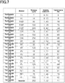
- Fig. 7 shows the measurement results of the measurement intensity ⁇ m for the examination marker of each test example.
- the measurement intensity ⁇ m of Test Example 1-1 was 0.00 mW/cm 2
- the measurement intensity ⁇ m of Test Example 1-2 was 0.00 mW/cm 2
- the measurement intensity ⁇ m of Test Example 1-3 was 1.43 mW/cm 2
- the measurement intensity ⁇ m of Test Example 1-4 was 1.39 mW/cm 2
- the measurement intensity ⁇ m of Test Example 1-5 was 0.82 mW/cm 2
- the measurement intensity ⁇ m of Test Example 1-6 was 1.61 mW/cm 2 .
- the measurement intensity ⁇ m of Test Example 1-7 was 1.28 mW/cm 2
- the measurement intensity ⁇ m of Test Example 1-8 was 1.23 mW/cm 2
- the measurement intensity ⁇ m of Test Example 1-9 was 1.54 mW/cm 2 .
- the measurement intensity ⁇ m of Test Example 1-10 was 1.36 mW/cm 2
- the measurement intensity ⁇ m of Test Example 1-11 was 1.12 mW/cm 2
- the measurement intensity ⁇ m of Test Example 1-12 was 1.71 mW/cm 2
- the measurement intensity ⁇ m of Test Example 1-13 was 1.67 mW/cm 2
- the measurement intensity ⁇ m of Test Example 1-14 was 1.69 mW/cm 2
- the measurement intensity ⁇ m of Test Example 1-15 was 1.37 mW/cm 2 .
- the measurement intensity ⁇ m of Test Example 1-16 was 1.18 mW/cm 2
- the measurement intensity ⁇ m of Test Example 1-17 was 1.70 mW/cm 2
- the measurement intensity ⁇ m of Test Example 1-18 was 1.68 mW/cm 2
- the measurement intensity ⁇ m of Test Example 1-19 was 1.48 mW/cm 2
- the measurement intensity ⁇ m of Test Example 1-20 was 1.14 mW/cm 2
- the measurement intensity ⁇ m of Test Example 1-21 was 1.32 mW/cm 2 .
- Fig. 7 shows the microwave transmittance in each test example based on the reference intensity ⁇ 0 and the measurement intensity ⁇ m in each test example. That is, as shown in Fig. 7 , the transmittance of Test Example 1-1 was 0%, the transmittance of Test Example 1-2 was 0%, and the transmittance of Test Example 1-3 was 78%. Further, the transmittance of Test Example 1-4 was 75%, the transmittance of Test Example 1-5 was 44%, and the transmittance of Test Example 1-6 was 87%. Further, the transmittance of Test Example 1-7 was 69%, the transmittance of Test Example 1-8 was 66%, and the transmittance of Test Example 1-9 was 84%.
- the transmittance of Test Example 1-10 was 74%
- the transmittance of Test Example 1-11 was 61%
- the transmittance of Test Example 1-12 was 92%
- the transmittance of Test Example 1-13 was 91%
- the transmittance of Test Example 1-14 was 92%
- the transmittance of Test Example 1-15 was 74%
- the transmittance of Test Example 1-16 was 64%
- the transmittance of Test Example 1-17 was 92%
- the transmittance of Test Example 1-18 was 91%.
- the transmittance of Test Example 1-19 was 79%
- the transmittance of Test Example 1-20 was 62%
- the transmittance of Test Example 1-21 was 71%.
- a breast scan using a probe was performed via the examination marker of each test example, and whether a three-dimensional image capable of diagnosing the breast could be generated was determined.
- the examination markers of Test Example 1-3, Test Example 1-4, Test Example 1-6, Test Example 1-9, Test Example 1-10, Test Examples 1-12 to 1-15, Test Examples 1-17 to 1-19, and Test Example 1-21 were able to generate a three-dimensional image when adhered to the subject.
- the examination markers of Test Example 1-1, Test Example 1-2, Test Example 1-5, Test Example 1-7, Test Example 1-8, Test Example 1-11, Test Example 1-16, and Test Example 1-20 caused attenuation of microwaves in the examination marker when adhered to the subject, and the transmittance was insufficient to generate a three-dimensional image.
- the examination marker provided with the marker body having a transmittance of 70% or higher to microwaves was able to generate a three-dimensional image that can be used for diagnosis of the breast.
- the adhesive for forming the adhesive layer 15 may be an adhesive other than urethane-based adhesives.
- the adhesive for forming the adhesive layer 15 may be an acrylic adhesive.
- the separable film 13 may be omitted.
- advantages similar to the above (1-1) can be obtained as long as the marker body 10A or 10B can display the scan index, and the marker body 10A or 10B has a transmittance of 70% or higher to microwaves.
- the protective film 14 may be omitted.
- advantages similar to the above (1-1) can be obtained as long as the marker body 10A or 10B can display the scan index, and the marker body 10A or 10B has a transmittance of 70% or higher to microwaves.
- the site to be examined is not limited to the breast, and may be other positions in the subject body. That is, the examination marker 10 may also be used for diagnostic imaging other than mammography.
- FIG. 1 , 4 , and 8 to 11 a second embodiment of an examination marker will be described.
- components common to those in the first embodiment are denoted by the same reference signs as in the first embodiment, and detailed description thereof will be omitted.
- an examination marker, usage of the examination marker, and test examples are each described.
- FIG. 1 With reference to Figs. 1 and 8 , an examination marker will be described.
- a configuration of a third example of the examination marker will be described with reference to Fig. 1
- a fourth example of the examination marker will be described with reference to Fig. 8 .
- the examination marker in the present embodiment is a marker for use in mammography, which is an example of diagnostic imaging using microwaves.
- the examination marker is a marker to be adhered to the breast, which is a site examined in mammography.
- the third example of the examination marker 10 has the same structure as that of the first example of the examination marker 10 in the first embodiment, which was described earlier with reference to Fig. 1 .
- the base film 11 of the present embodiment satisfies two conditions described below.
- the examination marker 10 has a tensile elongation at break and a tensile strength at 100% elongation suitable for adhesion to a site to be examined. Accordingly, the examination marker 10 can be easily adhered to a site to be examined.
- the tensile elongation at break can be calculated in accordance with JIS K 7161-1:2014 (ISO 527-1) and JIS K 7127:1999 (ISO 527-3).
- the tensile elongation at break can be calculated by using a tensile strain at break when an object to be measured does not have a yield point, and a nominal tensile strain at break when an object to be measured has a yield point.
- the tensile strength at 100% elongation is a value obtained by dividing the magnitude of the force measured when the strain defined in JIS K 7161-1:2014 (ISO 527-1) reaches a predetermined value (100%) by the width of the test piece.
- the polyurethane resin for forming the base film 11 includes at least one selected from the group consisting of ether-based polyurethane resin, ester-based polyurethane resin, and carbonate-based polyurethane resin. Accordingly, a base film 11 having high adhesion suitability and high moisture permeability can be provided.
- the ether-based polyurethane resin is a polyurethane resin produced using an ether-based polyol containing an ether bond (-O-).
- the ester-based polyurethane resin is a polyurethane resin produced using an ester-based polyol containing an ester bond (-COO-).
- the base film 11 may have a thickness of, for example, 5 ⁇ m or more and 30 ⁇ m or less.
- the base film 11 has a pair of surfaces facing away from each other.
- the pair of surfaces facing away from each other are composed of the front surface 11F and the rear surface 11R.
- the coordinate grid 12 is provided on the rear surface 11R.
- the base film 11 is transparent or translucent.
- a portion of the base film 11 other than the coordinate grid 12 preferably has a total light transmittance according to JIS K 7361-1 of 50% or more.
- the examination marker 10 further includes the separable film 13 and the protective film 14.
- the separable film 13 is detachably laminated on the front surface 11F of the base film 11.
- the protective film 14 is detachably laminated on the rear surface 11R of the base film 11.
- a portion of the examination marker 10 other than the coordinate grid 12 preferably has a total light transmittance according to JIS K 7361-1 of 30% or more, and more preferably 50% or more.
- the protective film 14 is transparent or translucent.
- the protective film 14 preferably has a total light transmittance of 30% or more, and more preferably 50% or more.
- the fourth example of the examination marker 10 further includes a gel layer 17 in addition to the base film 11, the separable film 13, and the protective film 14.
- the gel layer 17 is made of an aliphatic hydrocarbon that has a higher transmissivity to microwaves than water does.
- the gel layer 17, which is provided on the base film 11, has viscosity that enables adhesion of the base film 11 to the breast. That is, the gel layer 17 has a microwave transmittance higher than that of water. Due to the examination marker 10 provided with the gel layer 17, it is not required to apply a drug to a site to be examined to adhere the base film 11 to the breast. Accordingly, the base film 11 can be easily adhered to the breast.
- the gel layer 17 is made of an aliphatic hydrocarbon in the form of an ointment.
- the gel layer 17 covers the rear surface 11R of the base film 11. Accordingly, since the coordinate grid 12 is sandwiched between the base film 11 and the gel layer 17, the coordinate grid 12 does not form the outer surface of the examination marker 10. Therefore, the coordinate grid 12 is not likely to be detached from the base film 11.
- the gel layer 17 is located between the base film 11 and the protective film 14 in the thickness direction of the examination marker 10.
- a surface of the gel layer 17 in contact with the base film 11 is a front surface 17F, and a surface facing away from the front surface 17F is a rear surface 17R.
- the gel layer 17 covers the entire surface of the coordinate grid 12, and has a thickness sufficient to make the rear surface 17R substantially flat.
- the gel layer 17 is transparent or translucent.
- the gel layer 17 preferably has a shear viscosity at 30°C of 1,000 mPa ⁇ s or more and 200,000 mPa ⁇ s or less. More preferably, the shear viscosity at 30°C of the gel layer 17 is 5,000 mPa ⁇ s or more and 50,000 mPa ⁇ s or less.
- the shear viscosity is specified as in JIS Z 8803:2011.
- the gel layer 17 When the shear viscosity is 1,000 mPa ⁇ s or more, the gel layer 17 enables adhesion of the base film 11 to the breast with high reliability. On the other hand, when the shear viscosity is 200,000 mPa ⁇ s or less, the base film 11 is not likely to have wrinkling or waviness during application of the gel layer 17 to the base film 11. In addition, when the shear viscosity is 200,000 mPa ⁇ s or less, the gel layer 17 is not likely to have stickiness that causes discomfort to the subject, and wiping off of the gel layer 17 can be performed without difficulty.
- the gel layer 17 is preferably made of at least one selected from the group consisting of paraffin, squalane, and ceresin. These materials enable the gel layer 17 to reliably transmit microwaves, and reduce irritation of the subject's skin.
- the user first removes the separable film 13 and the protective film 14 from the base film 11.
- the separable film 13 may be removed earlier than the protective film 14, or the protective film 14 may be removed earlier than the separable film 13.
- aliphatic hydrocarbon having the form of an ointment which is similar to the material forming the gel layer 17 is applied to the breast of the subject.
- the base film 11 is applied to the breast via aliphatic hydrocarbon in the form of an ointment.
- the user removes the separable film 13 from the base film 11, and removes the protective film 14 from the gel layer 17.
- the separable film 13 may be removed earlier than the protective film 14, or the protective film 14 may be removed earlier than the separable film 13.
- the base film 11 is adhered to the breast B of the subject S via an aliphatic hydrocarbon H in the form of an ointment.
- a 12- ⁇ m thick PET film (manufactured by Toray Industries, Inc., Lumirror S10) (Lumirror is a registered trademark) was prepared as a base film of Test Example 2-1.
- a 4.5- ⁇ m thick PET film (manufactured by Toray Industries, Inc., Lumirror F48) was prepared as a base film of Test Example 2-2.
- a 75- ⁇ m thick PET film provided with a release layer (manufactured by Toray Industries, Inc., Cerapeel BX-9) (Cerapeel is a registered trademark) was prepared as a separable film.
- an EVA resin ethylene-vinyl acetate copolymer resin
- Novatec LV440 ethylene-vinyl acetate copolymer resin
- the separable film was then removed to obtain a base film of Test Example 2-3.
- Abase film of Test Example 2-4 was obtained in the same manner as in Test Example 2-3 except that the thickness of the base film in Comparative Example 2-3 was changed to 15 ⁇ m.
- Abase film of Test Example 2-5 was obtained in the same manner as in Test Example 2-3 except that the thickness of the base film in Test Example 2-3 was changed to 5 ⁇ m.
- a 30- ⁇ m thick PU film made of ether-based polyurethane resin (manufactured by Nihon Matai Co., Ltd., Esmer URS) (Esmer is a registered trademark) was prepared as a base film of Test Example 2-6.
- a 15- ⁇ m thick PU film made of ether-based polyurethane resin (manufactured by Okura Industrial Co., Ltd, Silklon HVL85) (Silklon is a registered trademark) was prepared as a base film of Test Example 2-7.
- a 5- ⁇ m thick PU film (manufactured by Nakajima Industrial Co., Ltd, thin urethane film) was prepared as a base film of Test Example 2-8.
- a water transfer tattoo sticker (manufactured by 3M Japan Ltd., A-One transfer sticker, product number: 52103) was prepared. Then, a 5- ⁇ m thick PVAlayer, which is an image-receiving layer, was prepared as a base film of Test Example 2-9.
- each examination marker was cut into a dumbbell shape (test piece type 5), and a tensile elongation at break of each examination marker was measured in accordance with the method according to JIS K 7161-1:2014. Specifically, a tensile elongation at break was measured by using a universal tester (Autograph AGS-X, load cell 1kN, manufactured by Shimadzu Corporation). The test piece was fixed at two positions with grips of the universal tester with the distance between the tips of the grips being set to 80 mm. While the tensile rate was set to 300 mm/min, the test piece was pulled between the fixed positions. Thus, an elongation at break of each test piece was obtained.
- a universal tester Autograph AGS-X, load cell 1kN, manufactured by Shimadzu Corporation
- each examination marker was cut into a dumbbell shape (test piece type 5), and the tensile strength at 100% elongation of each examination marker was calculated in accordance with the method according to JIS K 7161-1:2014. Specifically, the tensile strength at 100% elongation was calculated by using a universal tester (as above). The test piece was fixed at two positions with grips of the universal tester with the distance between the tips of the grips being set to 80 mm. While the tensile rate was set to 300 mm/min, the test piece was pulled between the fixed positions, and the magnitude of the measured force was divided by the width of the test piece. Thus, a tensile strength at 100% elongation was calculated.
- Adhesion suitability of the examination marker was evaluated by using a breast cancer palpation training model (manufactured by Tanac Co., Ltd.).
- the base film was adhered to the model breast via aliphatic hydrocarbon in the form of an ointment, which is made of paraffin and has a shear viscosity at 30°C of 10,000 mPa ⁇ s, and the following items were evaluated.
- the viscosity of the aliphatic hydrocarbon was measured in the following procedure.
- the aliphatic hydrocarbon to be measured was held at 30°C and measured in accordance with JIS Z 8803:2011 "Method for measuring viscosity with a single cylinder rotational viscometer” by using a B-type viscometer (manufactured by Toki Sangyo Co., Ltd, TVB-25L TM rotor 2).
- the aliphatic hydrocarbon was used after stirring for 1 minute.
- the base film made of EVA resin had adhesion suitability when the thickness was 15 ⁇ m or less. Further, the base film made of polyurethane resin also had adhesion suitability even when the thickness was 30 ⁇ m. However, when the base film had thickness of 30 ⁇ m, wrinkling occurred in the base film although it did not affect the examination. Therefore, the thickness of the base film made of polyurethane resin is preferably 30 ⁇ m or less. Further, the base film made of PVA resin showed no wrinkling.
- the base film made of PET resin had poor adhesion suitability.
- the reason for this result seems to be that the base film made of PET resin, which has low tensile strength, was not sufficiently stretched when the base film was adhered to the site to be examined.
- the adhesion suitability can be improved when the base film has a tensile elongation at break of 130% or more and a tensile strength at 100% elongation of 4 N/cm or less.
- the synthetic resin for forming the base film 11 may be a resin other than polyurethane resin.
- the synthetic resin for forming the base film 11 may be EVA resin, PVA resin, or the like.
- the material for forming the gel layer 17 may also be aliphatic hydrocarbon in the form of an ointment other than paraffin, squalane, and ceresin, as long as it has a higher transmissivity to microwaves than water does and adhere the base film 11 to the breast B.
- the gel layer 17 may also have a viscosity lower than 1,000 mPa ⁇ s or higher than 200,000 mPa ⁇ s as long as the gel layer 17 enables adhesion of the base film 11 to the breast B.
- the separable film 13 may be omitted. In this case as well, advantages similar to the above (2-1) can be obtained as long as the examination marker 10 includes the base film 11 that satisfies the above conditions 2-1 and 2-2.
- the protective film 14 may be omitted. In this case as well, advantages similar to the above (2-1) can be obtained as long as the examination marker 10 includes the base film 11 that satisfies the above conditions 2-1 and 2-2.
- the base film 11 other than the coordinate grid 12 may have a total light transmittance of 50% or more.
- the coordinate grid 12 on the base film 11 can be visually observed when the separable film 13 is removed from the front surface 11F of the base film 11 and the protective film 14 is removed from the rear surface 11R.
- a portion other than the coordinate grid 12 in the laminate composed of the separable film 13 and the base film 11 may have a total light transmittance of 50% or more.
- the coordinate grid 12 on the base film 11 can be visually observed in adhesion of the examination marker 10 to the site to be examined regardless of whether the separable film 13 is removed or not removed from the base film 11.
- FIG. 2 , 12 and 13 a third embodiment of an examination marker will be described.
- components common to those in the examination marker 10 of the first embodiment are denoted by the same reference signs as in the first embodiment, and detailed description thereof will be omitted.
- an examination marker and test examples are each described.
- the examination marker in the present embodiment is a marker for use in mammography, which is an example of diagnostic imaging using microwaves.
- the examination marker is a marker to be adhered to the breast, which is a site examined in mammography.
- the examination marker 10 has the same structure as that of the second example of the examination marker 10 in the first embodiment, which was described earlier with reference to Fig. 2 .
- the base film 11 is made of polyurethane resin.
- the adhesive layer 15 is made of urethane-based adhesive.
- the adhesive layer 15 is laminated on the base film 11.
- the adhesive layer 15 has a thickness of 5 ⁇ m or more and 25 ⁇ m or less.
- a laminate composed of the base film 11 and the adhesive layer 15 satisfies the following three conditions.
- the examination marker 10 has a tensile elongation at break and a tensile stress at 100% elongation suitable for adhesion to a site to be examined. Accordingly, the examination marker 10 can be easily adhered to a site to be examined. Further, due to the water vapor transmission rate of the examination marker 10 being within the above range, sweating at the site to be examined can be suppressed when the examination marker 10 is adhered to a site to be examined.
- the polyurethane resin for forming the base film 11 includes one selected from the group consisting of ether-based polyurethane resin, ester-based polyurethane resin, and carbonate-based polyurethane resin. Accordingly, the base film 11 having high adhesion suitability and high water vapor transmission rate can be provided.
- the ether-based polyurethane resin is a polyurethane resin produced using an ether-based polyol containing an ether bond (-O-).
- the ester-based polyurethane resin is a polyurethane resin produced using an ester-based polyol containing an ester bond (-COO-).
- the base film 11 When the base film 11 is formed of an ether-based polyurethane resin, the base film 11 preferably has a thickness of 30 ⁇ m or less. The base film 11 may have a thickness of, for example, 5 ⁇ m or more and 30 ⁇ m or less. When the base film 11 is formed of an ester-based polyurethane resin, the base film 11 may have a thickness of, for example, 5 ⁇ m or more and 15 ⁇ m or less. When the base film 11 is formed of a carbonate-based polyurethane resin, the base film 11 may have a thickness of, for example, 5 ⁇ m or more and 15 ⁇ m or less.
- the base film 11 has a pair of surfaces facing away from each other.
- the pair of surfaces facing away from each other are composed of the front surface 11F and the rear surface 11R.
- One of the pair of surfaces is a guide surface on which the coordinate grid 12 is printed.
- the coordinate grid 12 is provided on the rear surface 11R. That is, the rear surface 11R is an example of the guide surface.
- the base film 11 is transparent or translucent.
- the total light transmittance according to JIS K 7361-1 is preferably 30% or more, and more preferably 50% or more.
- the adhesive layer 15 is transparent or translucent.
- the total light transmittance of the adhesive layer 15 is preferably 50% or more.
- the separable film 13 and the protective film 14 are preferably made of a transparent or translucent synthetic resin film.
- a 12- ⁇ m thick PET film (manufactured by Toray Industries, Inc., Lumirror S10) (Lumirror is a registered trademark) was prepared as a base film. Further, a protective film having a thickness of 38 ⁇ m and composed of a PET film and a release layer (manufactured by Toray Industries, Inc., Cerapeel WZ) (Cerapeel is a registered trademark) was prepared. An acrylic adhesive (manufactured by CosMED Pharmaceutical Co. Ltd., HiPAS10) (HiPAS is a registered trademark) was applied to the protective film by gravure coating, and dried. Thus, an adhesive layer having a thickness of 20 ⁇ m was obtained. Then, the base film was bonded to the adhesive layer to obtain a laminate. The laminate was aged in an environment of 40°C to obtain an examination marker of Test Example 3-1.
- Test Example 3-2 An examination marker of Test Example 3-2 was obtained in the same manner as in Test Example 3-1 except that the base film in Test Example 3-1 was changed to a 4.5- ⁇ m thick PET film (manufactured by Toray Industries, Inc., Lumirror F48).
- a 75- ⁇ m thick PET film provided with a release layer (manufactured by Toray Industries, Inc., Cerapeel BX-9) was prepared as a separable film. Then, an EVA resin (manufactured by Japan Polyethylene Corporation, Novatec LV440) (Novatec is a registered trademark) was subjected to extrusion lamination molding, using the separable film as a support, to form a 30- ⁇ m thick EVA film as a base film. Except for the above, the same manner as in Test Example 3-1 was used to obtain the examination marker of Test Example 3-3. When the protective film coated with the adhesive layer was bonded to the base film, the laminate composed of the separable film and the base film was bonded to the adhesive layer. Then, after the laminate composed of the separable film, the base film, the adhesive layer, and the protective film was aged, the separable film was removed to obtain the examination marker of Test Example 3-3.
- Test Example 3-4 An examination marker of Test Example 3-4 was obtained in the same manner as in Test Example 3-3 except that the thickness of the base film in Test Example 3-3 was changed to 15 ⁇ m.
- Test Example 3-5 An examination marker of Test Example 3-5 was obtained in the same manner as in Test Example 3-3 except that the thickness of the base film in Test Example 3-3 was changed to 5 ⁇ m.
- Test Example 3-6 An examination marker of Test Example 3-6 was obtained in the same manner as in Test Example 3-5 except that an adhesive layer in Test Example 3-5 was made of a urethane-based adhesive (manufactured by Toyochem Co., Ltd., SP-205). In formation of the adhesive layer, 1% of a curing agent (manufactured by Toyochem Co., Ltd., T-501B) was added to the urethane-based adhesive. Then, the urethane-based adhesive was stirred to obtain a coating liquid for forming an adhesive layer.
- a urethane-based adhesive manufactured by Toyochem Co., Ltd., SP-205
- a curing agent manufactured by Toyochem Co., Ltd., T-501B
- Test Example 3-7 An examination marker of Test Example 3-7 was obtained in the same manner as in Test Example 3-1 except that the base film in Test Example 3-1 was changed to a 30- ⁇ m thick PU film (manufactured by Nihon Matai Co., Ltd., Esmer URS) (Esmer is a registered trademark).
- Test Example 3-8 An examination marker of Test Example 3-8 was obtained in the same manner as in Test Example 3-7 except that the thickness of the adhesive layer in Test Example 3-7 was changed to 10 ⁇ m.
- Test Example 3-9 An examination marker of Test Example 3-9 was obtained in the same manner as in Test Example 3-7 except that the thickness of the adhesive layer in Test Example 3-7 was changed to 5 ⁇ m.
- Test Example 3-10 An examination marker of Test Example 3-10 was obtained in the same manner as in Test Example 3-7 except that the thickness of the adhesive layer in Test Example 3-7 was changed to 30 ⁇ m.
- a 30- ⁇ m thick PU film made of ether-based polyurethane resin (manufactured by Nihon Matai Co., Ltd., Esmer URS) was prepared as a base film. Further, a protective film having a thickness of 30 ⁇ m and composed of a PET film and a release layer (manufactured by Toray Industries, Inc., Cerapeel WZ) was prepared. 1% of a curing agent (manufactured by Toyochem Co., Ltd., T-501B) was added to a urethane-based adhesive (manufactured by Toyochem Co., Ltd., SP-205), and the mixture was stirred to prepare a coating liquid.
- a curing agent manufactured by Toyochem Co., Ltd., T-501B
- the coating liquid was applied to the protective film by gravure coating, and the urethane-based adhesive was dried.
- an adhesive layer having a thickness of 20 ⁇ m was obtained.
- the base film was bonded to the adhesive layer to obtain a laminate.
- the laminate was aged in an environment of 40°C to obtain an examination marker of Test Example 3-11.
- Test Example 3-12 An examination marker of Test Example 3-12 was obtained in the same manner as in Test Example 3-11 except that the thickness of the adhesive layer in Test Example 3-11 was changed to 10 ⁇ m.
- Test Example 3-13 An examination marker of Test Example 3-13 was obtained in the same manner as in Test Example 3-11 except that the thickness of the adhesive layer in Test Example 3-11 was changed to 5 ⁇ m.
- Test Example 3-14 An examination marker of Test Example 3-14 was obtained in the same manner as in Test Example 3-11 except that the thickness of the adhesive layer in Test Example 3-11 was changed to 30 ⁇ m.
- Test Example 3-15 An examination marker of Test Example 3-15 was obtained in the same manner as in Test Example 3-1 except that the base film in Test Example 3-1 was changed to a 15- ⁇ m thick PU film made of ether-based polyurethane resin (manufactured by Okura Industrial Co., Ltd, Silklon HVL85) (Silklon is a registered trademark).
- ether-based polyurethane resin manufactured by Okura Industrial Co., Ltd, Silklon HVL85
- Test Example 3-16 An examination marker of Test Example 3-16 was obtained in the same manner as in Test Example 3-11 except that the base film in Test Example 3-11 was changed to a 15- ⁇ m thick PU film made of ether-based polyurethane resin (manufactured by Okura Industrial Co., Ltd, Silklon HVL85).
- Test Example 3-17 An examination marker of Test Example 3-17 was obtained in the same manner as in Test Example 3-1 except that the base film in Test Example 3-1 was changed to a 5- ⁇ m thick PU film (manufactured by Nakajima Industrial Co., Ltd, thin urethane film).
- Test Example 3-18 An examination marker of Test Example 3-18 was obtained in the same manner as in Test Example 3-17 except that the thickness of the adhesive layer in Test Example 3-17 was changed to 10 ⁇ m.
- Test Example 3-19 An examination marker of Test Example 3-19 was obtained in the same manner as in Test Example 3-17 except that the thickness of the adhesive layer in Test Example 3-17 was changed to 5 ⁇ m.
- Test Example 3-20 An examination marker of Test Example 3-20 was obtained in the same manner as in Test Example 3-17 except that the thickness of the adhesive layer in Test Example 3-17 was changed to 30 ⁇ m.
- Test Example 3-21 An examination marker of Test Example 3-21 was obtained in the same manner as in Test Example 3-11 except that the base film in Test Example 3-11 was changed to a 5- ⁇ m thick PU film (manufactured by Nakajima Industrial Co., Ltd, thin urethane film).
- Test Example 3-22 An examination marker of Test Example 3-22 was obtained in the same manner as in Test Example 3-21 except that the thickness of the adhesive layer in Test Example 3-21 was changed to 10 ⁇ m.
- Test Example 3-23 An examination marker of Test Example 3-23 was obtained in the same manner as in Test Example 3-21 except that the thickness of the adhesive layer in Test Example 3-21 was changed to 5 ⁇ m.
- Test Example 3-24 An examination marker of Test Example 3-24 was obtained in the same manner as in Test Example 3-21 except that the thickness of the adhesive layer in Test Example 3-21 was changed to 30 ⁇ m.
- a water transfer tattoo sticker (manufactured by 3M Japan Ltd., A-One transfer sticker, product number: 52103) was prepared. Then, in place of the base film, an enclosed adhesive layer was bonded to a PVA layer, which is an image-receiving layer, to thereby obtain an examination marker of Test Example 3-25. Since the PVA layer was applied to a release paper, the release paper was moistened using a tissue wetted with water after the PVA layer was bonded to the adhesive layer to thereby transfer the PVA layer to the adhesive layer. Thus, the PVA layer was removed from the release paper. The laminate including the PVA layer and the adhesive layer was left standing in an environment of 40°C for 2 hours to sufficiently dry a surface of the PVA layer.
- a 75- ⁇ m thick PET film provided with a release layer (manufactured by Toray Industries, Inc., Cerapeel BX-9) was prepared as a separable film. Then, an aqueous polyurethane containing ester-based polyol (manufactured by Mitsui Chemicals, Inc., TAKELAC WS-5984) (TAKELAC is a registered trademark) was applied and dried. Subsequently, the dried layer was left at room temperature for aging for 2 days to thereby obtain a base film having a thickness of 15 ⁇ m. An adhesive layer was formed on the base film in the same manner as that in Test Example 3-6 to thereby obtain an examination marker of Test Example 3-26.
- Test Example 3-27 An examination marker of Test Example 3-27 was obtained in the same manner as in Test Example 3-26 except that the thickness of the adhesive layer in Test Example 3-26 was changed to 10 ⁇ m.
- Test Example 3-28 An examination marker of Test Example 3-28 was obtained in the same manner as in Test Example 3-26 except that the thickness of the base film in Test Example 3-26 was changed to 5 ⁇ m.
- Test Example 3-29 An examination marker of Test Example 3-29 was obtained in the same manner as in Test Example 3-28 except that the thickness of the adhesive layer in Test Example 3-28 was changed to 10 ⁇ m.
- Test Example 3-30 An examination marker of Test Example 3-30 was obtained in the same manner as in Test Example 3-26 except that the aqueous polyurethane containing ester-based polyol in Test Example 3-26 was changed to aqueous polyurethane containing ether-based polyol (manufactured by Mitsui Chemicals, Inc., TAKELAC WS-6021).
- Test Example 3-31 An examination marker of Test Example 3-31 was obtained in the same manner as in Test Example 3-30 except that the thickness of the adhesive layer in Test Example 3-30 was changed to 10 ⁇ m.
- Test Example 3-32 An examination marker of Test Example 3-32 was obtained in the same manner as in Test Example 3-30 except that the thickness of the base film in Test Example 3-30 was changed to 5 ⁇ m.
- Test Example 3-33 An examination marker of Test Example 3-33 was obtained in the same manner as in Test Example 3-30 except that the thickness of the adhesive layer in Test Example 3-30 was changed to 10 ⁇ m.
- Test Example 3-34 An examination marker of Test Example 3-34 was obtained in the same manner as in Test Example 3-26 except that the aqueous polyurethane containing ester-based polyol in Test Example 3-26 was replaced by an aqueous polyurethane containing carbonate-based polyol (manufactured by Mitsui Chemicals, Inc., TAKELAC W-6110).
- Test Example 3-35 An examination marker of Test Example 3-35 was obtained in the same manner as in Test Example 3-34 except that the thickness of the adhesive layer in Test Example 3-34 was changed to 10 ⁇ m.
- Test Example 3-36 An examination marker of Test Example 3-36 was obtained in the same manner as in Test Example 3-34 except that the thickness of the base film in Test Example 3-34 was changed to 5 ⁇ m.
- Test Example 3-37 An examination marker of Test Example 3-37 was obtained in the same manner as in Test Example 3-36 except that the thickness of the adhesive layer in Test Example 3-36 was changed to 10 ⁇ m.
- the tensile stress at the time when the gauge length L 0 reached 100% elongation was calculated by dividing the tensile force applied at the time when the examination marker was elongated to 100% by the initial value of the cross-sectional area of the examination marker.
- Adhesion suitability of the examination marker was evaluated by using a breast cancer palpation training model (manufactured by Tanac Co., Ltd.). The examination marker was adhered to the model breast, the following three items were evaluated.
- the examination marker was subjected to an operation in which the examination marker was adhered to the breast, then removed from the breast, and then again adhered to the breast.
- the results were evaluated in three grades as below.
- the water vapor transmission rate of the examination marker was measured in accordance with the method according to JIS Z 0208 "Testing methods for determination of the water vapor transmission rate of moisture-proof packaging materials (dish method)."
- To measurement of the water vapor transmission rate calcium chloride (anhydrous) was weighed as a moisture absorbent. Then, the initial weight of a permeability cup including the moisture absorbent was measured by using an electronic scale. After the examination marker was left standing in an environment of 40°C and 90% RH for 2 hours, the permeability cup was weighed. Then, a gain in weight of the permeability cup was determined as the amount of water vapor transmitted.
- Test pieces of 5 cm square were cut from the examination marker. A test piece was adhered to the arm of three healthy subjects. The subjects rested quietly in a test room at 40°C and 20% RH for 5 minutes. After the test piece was removed from each subject, a portion of the subject's arm where the test piece was removed was observed to determine whether sweating had occurred.
- the thickness of the base film made of polyurethane resin is preferably 30 ⁇ m or less.
- the thickness of the base film is preferably 5 ⁇ m or more.
- the examination marker when the base film having high adhesion suitability was used, the examination marker was found to satisfy the tensile elongation at break of 420% or more and the tensile stress at 100% elongation of 10 MPa or less. Thus, the examination marker was able to have high adhesion suitability. Further, when the base film having high water vapor transmission rate was used, the examination marker had the water vapor transmission rate of 783g/m 2 ⁇ day or more, which reduced sweating.
- the base film made of PET resin had poor adhesion suitability.
- the reason for this result seems to be that the base film made of polyethylene terephthalate resin, which has low tensile elongation, was not sufficiently stretched when the examination marker was adhered to the site to be examined.
- the base film made of EVA resin it is possible to improve the adhesion suitability of the base film by reducing the thickness to 5 ⁇ m. However, this may cause occurrence of sweating to a degree that affects the examination in a portion where the examination marker is adhered since a base film made of EVA resin has a low water vapor transmission rate.
- the examination marker had low reworkability since the base film was torn. Meanwhile, since the base film made of PVA resin did not have wrinkling and lifting, the tensile elongation at break required to improve adhesion suitability may be 130% or more.
- a urethane-based adhesive had higher water vapor transmission rate than an acrylic adhesive.
- the examination marker had the water vapor transmission rate of 750 g/m 2 ⁇ day or more, which reduced sweating.
- the adhesive layer was thin, the examination marker had a high water vapor transmission rate, which reduced sweating.
- this causes the examination marker to be lifted due to the raised part of the nipple.
- the adhesive layer having a thickness of 30 ⁇ m had a low water vapor transmission rate, and was not likely to suppress sweating of the subject.
- the thickness of the adhesive layer is preferably 5 ⁇ m or more and 25 ⁇ m or less.
- the tensile elongations at break were different depending on the polyol constituting the polyurethane resin, and accordingly the examination results were different.
- Abase film made of ester-based polyurethane resin or ether-based polyurethane resin had higher tensile elongation at break than a base film made of carbonate-based polyurethane resin, and thus wrinkling was less likely to occur.
- the base film made of carbonate-based polyurethane resin was not likely to deform in the reworkability test even when the base film was thin.
- the base film made of ether-based polyurethane resin had higher water vapor transmission rate than the base film made of ester-based polyurethane resin or carbonate-based polyurethane resin, and thus sweating of the subject was suppressed even when the base film was thicker.
- the examination marker when the base film made of polyurethane resin having high adhesion suitability was used, the examination marker was found to satisfy the tensile elongation at break of 310% or more and the tensile stress at 100% elongation of 10 MPa or less. Thus, the examination marker was able to have high adhesion suitability. Further, when a base film made of polyurethane resin having high water vapor transmission rate was used, the examination marker was found to have the water vapor transmission rate of 783g/m 2 ⁇ day or more, which reduced sweating.
- the synthetic resin for forming the base film 11 may be a resin other than polyurethane resin.
- the adhesive for forming the adhesive layer 15 may be a resin other than urethane-based adhesive.
- the separable film 13 may be omitted. In this case as well, advantages similar to the above (3-1) can be obtained as long as the examination marker 10 includes the base film 11 and the adhesive layer 15.
- the protective film 14 may be omitted. In this case as well, advantages similar to the above (3-1) can be obtained as long as the examination marker 10 includes the base film 11 and the adhesive layer 15.
- At least a portion other than the coordinate grid 12 in the laminate composed of the base film 11 and the adhesive layer 15 may have a total light transmittance of 50% or more.
- the coordinate grid 12 on the base film 11 can be visually observed when the separable film 13 is removed from the base film 11 and the protective film 14 is removed from the adhesive layer 15.
- a portion other than the coordinate grid 12 in the laminate composed of the separable film 13, the base film 11, and the base film 15 may have a total light transmittance of 50% or more.
- the coordinate grid 12 on the base film 11 can be visually observed during adhesion of the examination marker 10 to the site to be examined regardless of whether the separable film 13 is removed from the base film 11.
- a fourth embodiment of an examination marker will be described.
- components common to those in the examination marker 10 of the first embodiment are denoted by the same reference signs as in the first embodiment, and detailed description thereof will be omitted.
- an examination marker, a method of producing the examination marker, and test examples are each described.
- the examination marker in the present embodiment is a marker for use in mammography, which is an example of diagnostic imaging using microwaves.
- the examination marker is a marker to be adhered to the breast, which is a site examined in mammography.
- the examination marker 10 has the same structure as that of the second example of the examination marker 10 in the first embodiment, which was described earlier with reference to Fig. 2 .
- the examination marker 10 include the base film 11 and the adhesive layer 15.
- the base film 11 is provided with a coordinate grid 12 used for guiding a scan position in a site to be examined.
- the coordinate grid 12 is an example scan index.
- the adhesive layer 15 is laminated on the base film 11.
- the base film 11 includes the rear surface 11R, which is a surface in contact with the adhesive layer 15, and the front surface 11F facing away from the rear surface 11R.
- the front surface 11F is a surface scanned with a probe during the examination of a site to be examined.
- the front surface 11F of the base film 11 satisfies the following two conditions.
- the probe can smoothly move on the front surface 11F when the front surface 11F of the base film 11 is scanned with the probe. Accordingly, the front surface 11F of the base film 11 can be smoothly scanned with the probe.
- the examination marker 10 further includes the separable film 13.
- the separable film 13 has a surface to be coated made of a polypropylene resin or a polyethylene resin.
- the front surface 11F of the base film 11 is a surface in contact with the surface to be coated, and has a shape conforming to the surface to be coated.
- the surface to be coated of the separable film 13 preferably satisfies the following condition. (Condition 4-3)
- the arithmetic average roughness Ra according to JIS B 0601:2013 of the surface to be coated is 0.2 ⁇ m or more.
- the arithmetic average roughness Ra of the front surface 11F of the base film 11 tends to be smaller than the arithmetic average roughness Ra of the surface to be coated of the separable film 13. Further, the arithmetic average roughness Ra of the front surface 11F of the base film 11 tends to be larger as the arithmetic average roughness Ra of the surface to be coated of the separable film 13 becomes large.
- the arithmetic average roughness Ra of the surface to be coated of the separable film 13 is 0.2 ⁇ m or more. Accordingly, when the base film 11 is formed by applying a coating liquid for forming the base film 11 to the surface to be coated, the possibility that the front surface 11F of the base film 11 has the arithmetic average roughness Ra of 0.1 ⁇ m or more increases. Thus, an examination marker 10 including a base film 11 having a front surface 11F that can be more smoothly scanned with a probe can be obtained.
- the separable film 13 preferably has peel strength from the base film 11 that satisfies the following condition. (Condition 4-4)
- the peel strength according to JIS Z 0237:2009 is 0.3 N/25 mm or less.
- the peel strength is 0.3 N/25 mm or less, removal of the separable film 13 from the base film 11 can be performed without difficulty. This increases ease of handling of the examination marker 10. Further, with an increase in the arithmetic average roughness Ra of at least one of the surfaces at the interface between two layers, the peel strength between the two layers tends to increase. In addition, with an increase in the arithmetic average roughness Ra of at least one of surfaces at the interface between two layers, the adhesion suitability between the two layers tends to increase.
- the separable film 13 has a peel strength from the base film 11 of 0.3 N/25 mm or less. Accordingly, both smooth scanning with a probe and the ease of handling of the examination marker 10 can be improved.
- the front surface 11F of the base film 11 preferably further satisfies the following condition. (Condition 4-5)
- the arithmetic average roughness Ra according to JIS B 0601:2013 is less than 5 ⁇ m.
- the separable film 13 Due to the arithmetic average roughness Ra of the front surface 11F of the base film 11 being less than 5 ⁇ m, the possibility that the separable film 13 has the peel strength from the base film 11 of 0.3 N/25mm or less increases.
- the surface to be coated of the separable film 13 preferably further satisfies the following condition.
- the arithmetic average roughness Ra according to JIS B 0601:2013 is less than 7 ⁇ m.
- the surface to be coated of the separable film 13 has the arithmetic average roughness Ra of less than 7 ⁇ m, when the base film 11 is formed by applying a coating liquid for forming the base film 11 to the surface to be coated, the possibility that the front surface 11F of the base film 11 has the arithmetic average roughness Ra of less than 5 ⁇ m increases. Accordingly, removal of the separable film 13 from the base film 11 can be performed without difficulty.
- the synthetic resin for forming the base film 11 may be, for example, a polyurethane resin.
- the polyurethane resin includes at least one selected from the group consisting of ether-based polyurethane resin, ester-based polyurethane resin, and carbonate-based polyurethane resin. Accordingly, the base film 11 having high adhesion suitability and high water vapor transmission rate can be provided.
- the ether-based polyurethane resin is a polyurethane resin produced using an ether-based polyol containing an ether bond (-O-).
- the ester-based polyurethane resin is a polyurethane resin produced using an ester-based polyol containing an ester bond (-COO-).
- the base film 11 may have a thickness of, for example, 5 ⁇ m or more and 30 ⁇ m or less.
- the base film 11 is transparent or translucent.
- the total light transmittance according to JIS K 7361-1 is preferably 30% or more, and more preferably 50% or more.
- the adhesive layer 15 is transparent or translucent.
- the adhesive layer 15 preferably has a total light transmittance of 30% or more, and more preferably 50% or more.
- the adhesive for forming the adhesive layer 15 may be, for example, a urethane-based adhesives.
- the adhesive layer 15 made of a urethane-based adhesive can have a high water vapor transmission rate.
- the adhesive layer 15 may have a thickness of, for example, 5 ⁇ m or more and 25 ⁇ m or less.
- a portion of the examination marker 10 other than the coordinate grid 12 preferably has a total light transmittance according to JIS K 7361-1 of 30% or more, and more preferably 50% or more.
- the separable film 13 and the protective film 14 are preferably made of a transparent or translucent synthetic resin film.
- a separable film 13 is first prepared for producing the examination marker 10. As described above, it is preferred to prepare a separable film 13 having the surface to be coated 13R, which is a surface to be coated with a coating liquid, with the arithmetic average roughness Ra of 0.2 ⁇ m or more and less than 7 ⁇ m.
- the material for the base film 11 and the material for the separable film 13, in particular the surface to be coated 13R are materials that can be separated from each other.
- the material for the base film 11 is preferably a polyurethane resin
- the material for the surface to be coated 13R is preferably a polypropylene resin or a polyethylene resin.
- the coating liquid When a coating liquid for forming the base film 11 is applied to the surface to be coated 13R of the base film 11, the coating liquid preferably has high wettability with the surface to be coated 13R. Accordingly, the base film 11 can be prevented from varying in thickness across the entirety of the surface to be coated 13R.
- the arithmetic average roughness Ra of the surface to be coated 13R of 0.2 ⁇ m or more as described above can also contribute to high wettability of the coating liquid with the surface to be coated 13R.
- a coating liquid for forming the base film 11 is applied to the surface to be coated 13R. Then, the coating liquid is dried to form the base film 11.
- the coating liquid for forming the base film 11 is dried while conforming to the unevenness of the surface to be coated 13R. Accordingly, the front surface 11F of the base film 11 has unevenness in accordance with the unevenness of the surface to be coated 13R.
- the coordinate grid 12 and the mark 16 are printed on the rear surface 11R of the base film 11.
- the coordinate grid 12 and the mark 16 are preferably printed by using a pigment that satisfies cosmetic standards stipulated in the "Order for enforcement of the act on securing quality, efficacy and safety of products including pharmaceuticals and medical devices."
- the solvent or dispersion medium for the pigment does not contain toluene.
- the adhesive layer 15 formed on the protective film 14 is bonded to the base film 11 to thereby obtain the examination marker 10 described above with reference to Fig. 2 .
- the adhesive for forming the adhesive layer 15 is preferably one that satisfies the biocompatibility stipulated in ISO 10993.
- Abiaxially oriented polypropylene (OPP) film (manufactured by Futamura Chemical Co., Ltd., FOS) was prepared as a separable film. Then, an aqueous polyurethane containing ether-based polyol (manufactured by Mitsui Chemicals, Inc., TAKELAC WS-6021) (TAKELAC is a registered trademark) was applied and dried. Subsequently, the dried layer was left at room temperature for aging for 2 days to thereby obtain a base film having a thickness of 15 ⁇ m. Thus, an examination marker of Test Example 4-1 was prepared.
- OPP Abiaxially oriented polypropylene
- Abiaxially oriented polypropylene (OPP) film manufactured by Futamura Chemical Co., Ltd., FOR-MP having a matte surface as one of a pair of surfaces was prepared.
- a non-matte surface which is a surface facing away from the matte surface, was subjected to sandblasting to form a fine texture.
- a base film was formed on the non-matte surface in the same manner as in Test Example 4-1.
- an examination marker of Test Example 4-2 was prepared.
- a polypropylene (PP) laminate release paper (manufactured by Lintec Corporation, EV130TPSG) was prepared as a separable film. Then, a base film was formed on one surface of the separable film in the same manner as in Test Example 4-1. Thus, an examination marker of Test Example 4-3 was prepared.
- PP polypropylene
- a polypropylene (PP) laminate release paper (manufactured by Lintec Corporation, EV130TPD) was prepared as a separable film. Then, a base film was formed on one surface of the separable film in the same manner as in Test Example 4-1. Thus, an examination marker of Test Example 4-4 was prepared.
- Test Example 4-5 An examination marker of Test Example 4-5 was obtained in the same manner as in Test Example 4-4 except that the aqueous polyurethane containing ether-based polyol was replaced by an aqueous polyurethane containing ether-based polyol (manufactured by Mitsui Chemicals, Inc., TAKELAC W-5661).
- Test Example 4-6 An examination marker of Test Example 4-6 was obtained in the same manner as in Test Example 4-4 except that the aqueous polyurethane containing ether-based polyol was replaced by an aqueous polyurethane containing carbonate-based polyol (manufactured by Mitsui Chemicals, Inc., TAKELAC W-6110).
- Test Example 4-7 An examination marker of Test Example 4-7 was obtained in the same manner as in Test Example 4-3 except that the separable film was replaced by a polypropylene (PP) laminate release paper (manufactured by Lintec Corporation, EV130TPD FN-L).
- PP polypropylene
- a dynamic friction coefficient of a front surface of the base film was measured in accordance with a method according to JIS K 7125:1999 "Plastics - Film and sheeting - Determination of the coefficients of friction.”
- a friction tester manufactured by Toyo Seiki Seisaku-sho, Ltd., TR-2 was used.
- a peel strength of the separable film from the base film was measured by a method according to JIS Z 0237:2009 "Testing methods of pressure-sensitive adhesive tapes and sheets.”
- a table-top precision universal tester manufactured by Shimadzu Corporation, AGS-X 5kN
- a test piece having 25 mm width was cut from each examination marker. Then, the separable film was fixed to the table-top precision universal tester, and a strength at 180° peel of the base film from the separable film was calculated.
- the arithmetic average roughness Ra of the base film refers to the arithmetic average roughness Ra on the front surface of the base film.
- the arithmetic average roughness Ra of the separable film refers to the arithmetic average roughness Ra on the surface to be coated of the separable film.
- the arithmetic average roughness Ra of the front surface of the base film increased.
- the arithmetic average roughness Ra of the front surface of the base film was less than 0.1, and the dynamic friction coefficient was more than 3. Further, in the examination marker of Test Example 4-1, when the front surface of the base film was scanned with the probe, it was found that the probe was caught on the front surface of the base film.
- the arithmetic average roughness Ra of the front surface of the base film was 0.1 or more, and the dynamic friction coefficient was 3 or less. Further, in the examination markers of Test Examples 4-2 to 4-7, when the front surface of the base film was scanned with the probe, it was found that the probe was not caught on the front surface of the base film.
- the front surface of the base film preferably has an arithmetic average roughness Ra of 0.1 ⁇ m or more, and a dynamic friction coefficient of 3.0 or less.
- the arithmetic average roughness Ra of the front surface of the base film can be 0.2 ⁇ m or more when the arithmetic average roughness Ra of the surface to be coated of the separable film, which corresponds to the front surface of the base film, is 0.3 ⁇ m or more.
- the arithmetic average roughness Ra of the front surface of the base film is preferably less than 5.0.
- the arithmetic average roughness Ra of the surface to be coated of the separable film, which corresponds to the front surface of the base film is preferably less than 7.0 ⁇ m.
- the adhesive for forming the adhesive layer 15 may be an adhesive other than urethane-based adhesives.
- the protective film 14 may be omitted. In this case as well, advantages similar to the above (4-1) can be obtained as long as the base film 11 satisfies the above conditions 4-1 and 4-2.
- a portion other than the coordinate grid 12 in the laminate composed of the separable film 13, the base film 11, and the base film 15 may have a total light transmittance of 50% or more.
- the coordinate grid 12 on the base film 11 can be visually observed during adhesion of the examination marker 10 to the site to be examined regardless of whether the separable film 13 is removed from the base film 11.
- a fifth embodiment of an examination marker will be described.
- the components common to those in the examination marker 10 of the first embodiment are denoted by the same reference signs as in the first embodiment, and detailed description thereof will be omitted.
- an examination marker and test examples are each described.
- the examination marker in the present embodiment is a marker for use in mammography, which is an example of diagnostic imaging using microwaves.
- the examination marker is a marker to be adhered to the breast, which is a site examined in mammography.
- the examination marker 10 has the same structure as that of the second example of the examination marker 10 in the first embodiment, which was described earlier with reference to Fig. 2 .
- the base film 11 is made of polyurethane resin.
- the adhesive layer 15 is made of a urethane-based adhesive. The adhesive layer 15 is laminated on the base film 11.
- the examination marker 10 of the present embodiment satisfies the following three conditions.
- the examination marker 10 due to the peel strength of the adhesive layer 15 being 6.0 N/25 mm or less, it is possible to prevent residue of the adhesive layer 15 on the breast. Further, since the breaking strength of the base film 11 is higher than the peel strength of the adhesive layer 15, tearing of the base film 11 is not likely to occur. Accordingly, the burden on the subject and the operator can be reduced. On the other hand, since the water vapor transmission rate of the laminate composed of the base film 11 and the adhesive layer 15 in accordance with JIS Z 0208 is 750 g/m 2 ⁇ day or more under the conditions of 40°C and 90% RH, sweating of the breast can be suppressed.
- the peel strength of the adhesive layer 15 is 1.5 N/25 mm or more, the adhesive layer 12 can be adhered to the breast while filling the level difference between the breast surface and the raised nipple, that is, unevenness formed by the breast surface and the nipple. Accordingly, the accuracy of examination can be improved.
- the adhesive layer 15 is made of a urethane-based adhesive, which is a synthetic resin having high permeability, sweating at the site to be examined where the adhesive layer 15 is adhered can be suppressed.
- the polyurethane resin for forming the base film 11 can include at least one selected from the group consisting of ether-based polyurethane resin, ester-based polyurethane resin, and carbonate-based polyurethane resin.
- the base film 11 is preferably made of an ether-based polyurethane resin.
- the ether-based polyurethane resin when used to form the base film 11 can increase the water vapor transmission rate of the base film 11.
- the base film 11 preferably has a thickness of 20 ⁇ m or less. Accordingly, occurrence of wrinkling in the base film 11 due to the base film 11 being excessively thick can be prevented when the base film 11 is adhered to the breast. Further, the base film 11 preferably has a thickness of 8 ⁇ m or more. Accordingly, occurrence of wrinkling in the base film 11 due to the base film 11 being excessively thin can be prevented when the base film 11 is adhered to the breast.
- the base film 11 preferably has a breaking strength of 6.3 N/25 mm or more and 10.4 N/25 mm or less. Accordingly, the thickness of the base film 11 can be within a range that enables a high water vapor transmission rate while preventing the base film 11 from being easily torn compared with the base film 11 having the breaking strength of more than 10.4 N/25 mm.
- the base film 11 is transparent or translucent.
- the total light transmittance according to JIS K 7361-1 is preferably 30% or more, and more preferably 50% or more.
- the adhesive layer 15 is transparent or translucent.
- the adhesive layer 15 preferably has a total light transmittance of 30% or more, and more preferably 50% or more.
- a portion of the examination marker 10 other than the coordinate grid 12 preferably has a total light transmittance according to JIS K 7361-1 of 30% or more, and more preferably 50% or more.
- A75- ⁇ m thick protective film (manufactured by Toray Advanced Film Co., Ltd., Cerapeel BX-9) (Cerapeel is a registered trademark) was prepared.
- a urethane-based adhesive (manufactured by Toyochem Co., Ltd., CYABINE SP-205) (CYABINE is a registered trademark) as a base resin, and a curing agent (manufactured by Toyochem Co., Ltd., T-501B) were prepared.
- the curing agent was added to the urethane-based adhesive so that the ratio of the number of moles of the isocyanate groups contained in the curing agent to the number of moles of the hydroxyl groups contained in the base resin (number of moles of isocyanate groups / number of moles of hydroxyl groups) (hereinafter, also referred to as a molar ratio between the base resin and the curing agent) becomes 0.13, and the mixture was stirred to prepare a coating liquid. Then, the coating liquid was applied to the protective film by gravure coating, and the urethane-based adhesive was dried. Thus, an adhesive layer having a thickness of 10 ⁇ m was obtained.
- Test Example 5-2 An examination marker of Test Example 5-2 was obtained in the same manner as in Test Example 5-1 except that the molar ratio between the base resin and the curing agent in Test Example 5-1 was changed to 0.19.
- Test Example 5-3 An examination marker of Test Example 5-3 was obtained in the same manner as in Test Example 5-1 except that the thickness of the adhesive layer in Test Example 5-1 was changed to 20 ⁇ m.
- Test Example 5-4 An examination marker of Test Example 5-4 was obtained in the same manner as in Test Example 5-2 except that the thickness of the adhesive layer in Test Example 5-2 was changed to 20 ⁇ m.
- a polypropylene (PP) laminate release paper (manufactured by Lintec Corporation, EV130TPD) was prepared as a separable film. Then, an aqueous polyurethane containing ether-based polyol (manufactured by Mitsui Chemicals, Inc., TAKELAC WS-6021) (TAKELAC is a registered trademark) was applied and dried. Subsequently, the dried layer was left at room temperature for aging for 2 days to thereby obtain a base film having a thickness of 10 ⁇ m. An examination marker of Test Example 5-5 was obtained by adhering the adhesive layer, prepared in the same manner as in Test Example 5-1 except that the thickness was changed to 15 ⁇ m, to the base film.
- Test Example 5-6 An examination marker of Test Example 5-6 was obtained in the same manner as in Test Example 5-5 except that the thickness of the base film in Test Example 5-5 was changed to 15 ⁇ m.
- Test Example 5-7 An examination marker of Test Example 5-7 was obtained in the same manner as in Test Example 5-6 except that the thickness of the adhesive layer in Test Example 5-6 was changed to 20 ⁇ m and the molar ratio between the base resin and the curing agent was changed to 0.03.
- Test Example 5-1 The base resin in Test Example 5-1 was replaced by an acrylic adhesive (manufactured by Nihon Gosei Kako Co., Ltd., COPONYL 8065) (COPONYL is a registered trademark), and a curing agent (manufactured by Tosoh Corporation, Coronate L-55E) (Coronate is a registered trademark) was prepared. Then, an examination marker of Test Example 5-8 was obtained in the same manner as in Test Example 5-1 except that the molar ratio between the base resin and the curing agent was changed to 0.15.
- an acrylic adhesive manufactured by Nihon Gosei Kako Co., Ltd., COPONYL 8065
- a curing agent manufactured by Tosoh Corporation, Coronate L-55E
- Test Example 5-9 An examination marker of Test Example 5-9 was obtained in the same manner as in Test Example 5-1 except that the molar ratio between the base resin and the curing agent in Test Example 5-1 was changed to 0.25.
- Test Example 5-10 An examination marker of Test Example 5-10 was obtained in the same manner as in Test Example 5-1 except that a 30- ⁇ m thick PU film (manufactured by Nihon Matai Co., Ltd., Esmer URS) (Esmer is a registered trademark) was prepared as a base film.
- Esmer is a registered trademark
- Test Example 5-11 An examination marker of Test Example 5-11 was obtained in the same manner as in Test Example 5-1 except that an acrylic adhesive (manufactured by Nihon Gosei Kako Co., Ltd., COPONYL N-4181) as a base resin and a curing agent (manufactured by Tosoh Corporation, Coronate L-55E) were prepared, and the thickness of the adhesive layer was changed to 20 ⁇ m.
- an acrylic adhesive manufactured by Nihon Gosei Kako Co., Ltd., COPONYL N-4181
- a curing agent manufactured by Tosoh Corporation, Coronate L-55E
- Test Example 5-12 An examination marker of Test Example 5-12 was obtained in the same manner as in Test Example 5-7 except that the molar ratio between the base resin and the curing agent in Test Example 5-7 was changed to 0.01.
- a water transfer tattoo sticker (manufactured by 3M Japan Ltd., transfer sticker, product number: 51112) was prepared.
- a transparent glue film composed of a PVA layer having a 5 ⁇ m thickness, and a separator having a 110 ⁇ m thickness and supporting the PVA layer was prepared.
- the separator was removed from the transparent adhesive film to obtain the PVA layer, which was used as a base film.
- an examination marker of Test Example 5-13 was obtained by adhering the adhesive layer, prepared in the same manner as in Test Example 5-1, to the base film.
- a peel strength of the examination marker was measured by a method according to JIS Z 0237:2009 "Testing methods of pressure-sensitive adhesive tapes and sheets.” Each examination marker was formed into a sample having a width of 25 mm. After the protective film was removed from the adhesive layer, the adhesive layer was adhered to a stainless test plate. Then, a 2 gk weight roller was rolled on the sample, reciprocating twice to apply a load to the sample, and the sample was left standing for 30 minutes or longer. Subsequently, the peel strength when the peel rate was 300 mm/min and the sample was peeled from the stainless test plate at 180° was measured by using a tensile tester.
- the water vapor transmission rate of the examination marker was measured in accordance with the method according to JIS Z 0208 "Testing methods for determination of the water vapor transmission rate of moisture-proof packaging materials (dish method)."
- To measurement of the water vapor transmission rate calcium chloride (anhydrous) was weighed as a moisture absorbent. Then, the initial weight of a permeability cup including the moisture absorbent was measured by using an electronic scale. After the examination marker was left standing in an environment of 40°C and 90% RH for 2 hours, the permeability cup was weighed. Then, a gain in weight of the permeability cup was determined as the amount of water vapor transmitted.
- Adhesion suitability of the examination marker was evaluated by using a breast cancer palpation training model (manufactured by Tanac Co., Ltd.). The examination marker was adhered to the model breast, the following three items were evaluated.
- the examination marker was subjected to an operation in which the examination marker was adhered to the breast, then removed from the breast, and then again adhered to the breast.
- the results were evaluated in three grades as below.
- An adhesive layer used for the examination marker was formed on a support made of a 12- ⁇ m thick PET film.
- the adhesive layer was adhered to the subject body, and left standing for 30 minutes or more. Then, the adhesive layer was peeled from the subject body at 180° by using a tensile tester. The peel rate was set at 300 mm/min. Whether adhesive residue was present when the adhesive layer was removed from the subject body, that is, whether part of the adhesive layer was left on the subject body was evaluated in two grades as below.
- Each examination marker was adhered to the subject body, and left standing for 30 minutes or more. Then, whether sweating occurred at the site where the examination marker was adhered was checked. The degree of sweating was evaluated in three grades as below.
- the laminate composed of the base film and the adhesive layer kept a high water vapor transmission rate.
- the laminate including the adhesive layer made of a polyurethane resin kept the water vapor transmission rate of 750 g/m 2 ⁇ day or more.
- the laminate had the water vapor transmission rate of 750 g/m 2 ⁇ day or more, sweating occurred to a degree that did not affect examination using microwaves.
- the laminate had a water vapor transmission rate of 850 g/m 2 ⁇ day or more, no sweating occurred.
- Test Examples 5-9 and 5-10 in which the adhesive layer has a peel strength of 1.2 N/25 mm or less, it was found that the examination marker was lifted due to the level difference between the nipple and the breast surface since it had insufficient adhesion to an uneven surface even when an adhesive layer was made of a polyurethane resin.
- Test Example 5-4 in which the adhesive layer has a peel strength of 1.6 N/25 mm or more, it was found that lifting of the laminate was reliably prevented.
- the adhesive layer preferably has a peel strength of 1.5 N/25 mm or more in order to prevent itself from being lifted due to the level difference between the nipple and the breast surface.
- the adhesive layer in which the adhesive layer had a peel strength of 7.2 N/25 mm, adhesion to the subject body was excessively high. As a result, adhesive residue was present when the adhesive layer was removed from the subject body. On the other hand, in Test Example 5-11, in which the adhesive layer had a peel strength of 5.4 N/25 mm or less, no adhesive residue was present. Therefore, the adhesive layer preferably has a peel strength of the 6.0 N/25 mm or less in order to prevent the adhesive residue.
- the adhesive layer preferably has a peel strength of 1.5 N/25 mm or more and 6.0 N/25 mm or less.
- the breaking strength is preferably larger than the peel strength, and a larger difference between the breaking strength and the peel strength is more preferred.
- the thickness of the base film is preferably less than 30 ⁇ m, and more preferably 20 ⁇ m or less.
- the thickness of the base film is preferably more than 5 ⁇ m, and more preferably more than 8 ⁇ m.
- the thickness of the base film can be within a range that can prevent the base film from being easily torn and maintain a high water vapor transmission rate of the base film.
- the adhesive for forming the adhesive layer 15 may be an adhesive other than urethane-based adhesives.
- the adhesive for forming the adhesive layer 15 may be an acrylic adhesive.
- advantages similar to the above (5-1) and (5-2) can be obtained as long as the examination marker 10 satisfies the above conditions 5-1 to 5-3.
- the separable film 13 may be omitted.
- advantages similar to the above (5-1) and (5-2) can be obtained as long as the examination marker 10 includes the base film 11 that satisfies the above conditions 5-1 to 5-3 and the adhesive layer 15.
- the protective film 14 may be omitted.
- advantages similar to the above (5-1) and (5-2) can be obtained as long as the examination marker 10 includes the base film 11 that satisfies the above conditions 5-1 to 5-3 and the adhesive layer 15.
- At least a portion other than the coordinate grid 12 in the laminate composed of the base film 11 and the adhesive layer 15 may have a total light transmittance of 50% or more.
- the coordinate grid 12 on the base film 11 can be visually observed when the separable film 13 is removed from the base film 11 and the protective film 14 is removed from the adhesive layer 15.
- a portion other than the coordinate grid 12 in the laminate composed of the separable film 13, the base film 11, and the base film 15 may have a total light transmittance of 50% or more.
- the coordinate grid 12 on the base film 11 can be visually observed in adhesion of the examination marker 10 to the site to be examined regardless of whether the separable film 13 is removed or not removed from the base film 11.
- a method for producing an examination marker which includes a base film, and an adhesive layer laminated on the base film comprising a step of forming the adhesive layer, wherein the step of forming the adhesive layer includes mixing a base resin having a urethane skeleton as a main chain, which has at least two ends, and a hydroxyl group on each end of the main chain, and a curing agent having a urethane skeleton as a main chain, which has at least two ends, and an isocyanate group on each end of the main chain, in which a ratio of the number of moles of the isocyanate groups to the number of moles of the hydroxyl groups is 0.02 or more and 0.2 or less.
- the peel strength of the adhesive layer can be sufficiently large to follow the uneven surface of the site to be examined and fill the level difference, that is, unevenness in the site to be examined, and sufficiently small to prevent residue of the adhesive layer from remaining at the site to be examined when the adhesive layer is removed from the site to be examined.
- FIG. 2 and 19 a sixth embodiment of an examination marker will be described.
- components common to those in the examination marker 10 of the first embodiment are denoted by the same reference signs as in the first embodiment, and detailed description thereof will be omitted.
- an examination marker and test examples are each described.
- the examination marker in the present embodiment is a marker for use in mammography, which is an example of diagnostic imaging using microwaves.
- the examination marker is a marker to be adhered to the breast, which is a site examined in mammography.
- the examination marker 10 has the same structure as that of the second example of the examination marker 10 in the first embodiment, which was described earlier with reference to Fig. 2 .
- a laminate composed of the base film 11 and the adhesive layer 12 satisfies two conditions described below.
- the base film 11 in the examination marker 10 satisfies the following condition.
- the laminate since the laminate has the tensile elongation at break of 130% or more and the tensile stress at 100% elongation of 10 MPa or less, the laminate composed of the base film 11 and the adhesive layer 15 can be stretched to a large extent with a small force.
- the laminate maintains high flexibility as described above since the base film 11 has a peel strength of 3.5 N/25 mm or less, it is possible to separate a portion of the laminate from another portion when they are in contact with each other by applying a force in a direction that separates the contact portions.
- the laminate due to the flexibility of the laminate, the laminate can easily follow the breast and be adhered thereto, and portions of the laminate that are in contact with each other can be easily separated.
- the examination marker 10 can be easily handled.
- the tensile elongation at break is calculated in accordance with JIS K7127:1999 (ISO 527-3:1995) "Plastics - Determination of tensile properties - Part 3: Test conditions for films and sheets” and JIS K7161-1:2014 (ISO 527-1:2012) "Plastics - Determination of tensile properties - Part 1: General principles.”
- JIS K7127:1999 ISO 527-3:1995
- JIS K7161-1:2014 ISO 527-1:2012
- the "nominal tensile strain at break" defined in the section 3.8.1 of the above standard is calculated as a tensile elongation at break.
- the tensile strain at break is calculated according to the formula (1) as below specified in the "Calculation and expression of test results" in the section 10 of the above standard.
- the nominal tensile strain at break is calculated according to the formula (2) as below specified in the "Calculation and expression of test results" in the section 10 of the above standard.
- ⁇ is a strain (%)
- L 0 is a gauge length of the test piece (mm)
- ⁇ L 0 is an increased amount in the gauge length of the test piece (mm).
- ⁇ t is a nominal strain (%)
- ⁇ y is a yield strain (%)
- L is an initial distance between the fixation tools (mm)
- ⁇ L t is an increased amount in the distance between the fixation tools from the yield point (mm).
- the tensile stress at 100% elongation is in accordance with JIS K7127:1999 (ISO 527-3:1995) "Plastics - Determination of tensile properties - Part 3: Test conditions for films and sheets," and calculated as a stress when the strain reaches a predetermined value (100%) in the "tensile stress at x% strain” defined in the section 3.6.3 of JIS K7161-1:2014 (ISO 527-1:2012) "Plastics - Determination of tensile properties - Part 1: General principles.”
- the tensile stress at 100% strain is calculated according to formula (3) as below specified in the "Calculation and expression of test results" in the section 10 of the above standard.
- ⁇ F / A
- ⁇ is a stress (MPa)
- F is a magnitude of the measured force (N)
- A is an initial cross sectional area of the test piece (mm 2 ).
- the peel strength is measured by a method in accordance with JIS Z0237:2009 "Testing methods of pressure-sensitive adhesive tapes and sheets.”
- the peel strength is measured in accordance with "Method 1: 180° peel adhesion from test plate" in the section 10.4.1 of the above standard.
- the base film 11 is made of a polyurethane resin.
- the polyurethane resin preferably includes at least one selected from the group consisting of ether-based polyurethane resin, ester-based polyurethane resin, and carbonate-based polyurethane resin. Accordingly, the base film 11 can be provided with high flexibility and easily adhered to the site to be examined.
- the ether-based polyurethane resin is a polyurethane resin produced using an ether-based polyol containing an ether bond (-O-).
- the ester-based polyurethane resin is a polyurethane resin produced using an ester-based polyol containing an ester bond (-COO-).
- the base film 11 preferably has a thickness of 5 ⁇ m or more and 30 ⁇ m or less.
- the polyurethane resin can include a first polyurethane resin and a second polyurethane resin.
- the first polyurethane resin has a glass transition temperature lower than a glass transition temperature of the second polyurethane resin. Since the two polyurethane resins included in the polyurethane resin for forming the base film 11 have different glass transition temperatures, both flexibility and low adhesion can be achieved in the base film 11. Of the polyurethane resins for forming the base film 11, the first polyurethane resin having a lower glass transition temperature tends to mainly provide the flexibility to the base film 11, while the second polyurethane resin having a higher glass transition temperature tends to mainly provide the low adhesion to the base film 11.
- the glass transition temperature of the first polyurethane resin can be 40°C, and the glass transition temperature of the second polyurethane resin can be 90°C. Accordingly, due to a large difference between the glass transition temperature of the first polyurethane resin and the glass transition temperature of the second polyurethane resin, the base film can exhibit both the flexibility and low adhesion.
- the examination marker 10 is typically used in an environment held at room temperature, that is, around 20°C.
- a difference between the glass transition temperature of the first polyurethane resin and the environmental temperature is small, and the glass transition temperature of the second polyurethane resin is significantly higher than the environmental temperature. Accordingly, the first polyurethane resin can increase the flexibility of the base film, while the second polyurethane resin can weaken the adhesion of the base film.
- a ratio (P2/P1) of a first mass (PI) of the first polyurethane resin to a second mass (P2) of the second polyurethane resin is preferably 1/25 or more and 1/5 or less. Accordingly, due to the ratio of the first mass to the second mass, the base film 11 can exhibit tensile elongation at break and tensile stress at 100% elongation that enable high flexibility, and peel strength that enables low adhesion.
- the adhesive layer 15 is made of a synthetic resin adhesive.
- the adhesive layer 15 is preferably made of a urethane-based adhesive.
- the adhesive layer 12 preferably has a thickness of 5 ⁇ m or more and 25 ⁇ m or less.
- the separable film 13 and the protective film 14 are preferably made of a transparent or translucent synthetic resin film.
- the separable film 13 preferably has a hardness higher than a hardness of the base film 11. Accordingly, when a portion of the separable film 13 comes into contact with another portion, the contact portions can be prevented from being adhered to each other.
- the laminate satisfies the conditions 6-1 and 6-2, the laminate is stretched to a large extent compared to a force applied to the laminate. Accordingly, the laminate has high conformability to the shape of the breast B, and wrinkling is not likely occur in the laminate.
- the base film 11 satisfies the condition 6-3, even when a portion of the base film 11 comes into contact with another portion, or when a portion of the adhesive layer 12 comes into contact with another portion when the laminate is stretched, it is possible to separate the contact portions. Therefore the examination marker 10 including the laminate composed of the base film 11 and the adhesive layer 12, which has high flexibility and low adhesion, can increase efficiency of mammography examination.
- a 75- ⁇ m thick PET film provided with a release layer (manufactured by Toray Advanced Film Co., Ltd., Cerapeel BX-9) (Cerapeel is a registered trademark) was prepared as a separable film. Then, an aqueous polyurethane containing ether-based polyol (manufactured by Mitsui Chemicals, Inc., TAKELAC WS-6021) (TAKELAC is a registered trademark) was applied and dried. Subsequently, the dried layer was left at room temperature for aging for 2 days to thereby obtain a base film having a thickness of 10 ⁇ m.
- a 38- ⁇ m thick PET film provided with a release layer (manufactured by Toray Advanced Film Co., Ltd., Cerapeel WZ) was prepared as a protective film.
- 1% of a curing agent (manufactured by Toyochem Co., Ltd., T-501B) was added to a urethane-based adhesive (manufactured by Toyochem Co., Ltd., SP-205), and the mixture was stirred to prepare a coating liquid.
- the coating liquid was applied to the protective film by gravure coating, and the urethane-based adhesive was dried.
- an adhesive layer having a thickness of 20 ⁇ m was obtained.
- the base film was bonded to the adhesive layer to obtain a laminate.
- the laminate was aged in an environment of 40°C to obtain an examination marker of Test Example 6-1.
- the first polyurethane resin an aqueous polyurethane having a glass transition temperature of 40°C and containing ether-based polyol (manufactured by Mitsui Chemicals, Inc., TAKELAC WS-6021) was prepared.
- the second polyurethane resin an aqueous polyurethane having a glass transition temperature of 90°C and containing ether-based polyol (manufactured by Mitsui Chemicals, Inc., TAKELAC W-6020) was prepared.
- the first polyurethane resin was mixed with the second polyurethane resin so that a ratio of the mass of the second polyurethane resin to the mass of the first polyurethane resin is 1/25.
- An examination marker of Test Example 6-2 was obtained in the same manner as in Test Example 6-1 except that the polyurethane resin obtained by mixing the first polyurethane resin with the second polyurethane resin was used in Test Example 6-1.
- Test Example 6-3 An examination marker of Test Example 6-3 was obtained in the same manner as in Test Example 6-2 except that the ratio of the mass of the second polyurethane resin to the mass of the first polyurethane resin in Test Example 6-2 was changed to 1/12.5.
- Test Example 6-4 An examination marker of Test Example 6-4 was obtained in the same manner as in Test Example 6-2 except that the ratio of the mass of the second polyurethane resin to the mass of the first polyurethane resin in Test Example 6-2 was changed to 1/10.
- Test Example 6-5 An examination marker of Test Example 6-5 was obtained in the same manner as in Test Example 6-2 except that the ratio of the mass of the second polyurethane resin to the mass of the first polyurethane resin in Test Example 6-2 was changed to 1/5.
- Test Example 6-6 An examination marker of Test Example 6-6 was obtained in the same manner as in Test Example 6-2 except that the ratio of the mass of the second polyurethane resin to the mass of the first polyurethane resin in Test Example 6-2 was changed to 1/2.
- Test Example 6-7 An examination marker of Test Example 6-7 was obtained in the same manner as in Test Example 6-2 except that the mass of the first polyurethane resin and the mass of the second polyurethane resin in Test Example 6-2 were equal.
- Test Example 6-8 An examination marker of Test Example 6-8 was obtained in the same manner as in Test Example 6-2 except that the ratio of the mass of the second polyurethane resin to the mass of the first polyurethane resin in Test Example 6-2 was changed to 5/1.
- Test Example 6-9 An examination marker of Test Example 6-9 was obtained in the same manner as in Test Example 6-2 except that the ratio of the mass of the second polyurethane resin to the mass of the first polyurethane resin in Test Example 6-2 was changed to 10/1.
- the tensile elongation at break was measured in accordance with JIS K7127:1999 (ISO 527-3:1995) "Plastics - Determination of tensile properties - Part 3: Test conditions for films and sheets” and JIS K7161-1:2014 (ISO 527-1:2012) "Plastics - Determination of tensile properties - Part 1: General principles.”
- the examination marker was cut into a dumbbell shape (test piece type 5), and a tensile strength at break was measured by using a tensile tester (manufactured by Shimadzu Corporation, AGS-X 5kN).
- the test rate was set to 300 mm/min, the gauge length L 0 was set to 25 mm, and the initial distance between the fixation tools L was set to 80 mm.
- the tensile strain at break was calculated as a tensile elongation at break.
- the nominal tensile strain at break was calculated as a tensile elongation at break.
- the laminate composed of only the base film and the adhesive layer was used.
- the test piece was prepared in accordance with JIS K7127:1999 (ISO 527-3:1995) "Plastics - Determination of tensile properties - Part 3: Test methods for films and sheets.” Then, the tensile stress at 100% elongation was calculated as a stress when the strain reaches 100% in accordance with JIS K7161-1:2014 (ISO 527-1:2012) "Plastics - Determination of tensile properties - Part 1: General principles.”
- Adhesion suitability of the examination marker was evaluated by using a breast cancer palpation training model (manufactured by Tanac Co., Ltd.). The examination marker was adhered to the model breast, and whether wrinkling occurred in the examination marker was evaluated in three grades as below. In the three grades, an examination marker evaluated as "good” or "fair” was determined as an examination marker having adhesion suitability.
- the peel strength was measured by a method in accordance with JIS Z0237:2009 "Testing methods of pressure-sensitive adhesive tapes and sheets.”
- a table-top precision universal tester manufactured by Shimadzu Corporation, AGS-X 5kN
- an SUS 304 plate having a BA surface finish were used.
- a test piece having 25 mm width was formed from the examination marker.
- a surface of the base film on a side opposite to that on which the adhesive layer was laminated was placed on the SUS plate, and the base film was pressure bonded to the SUS plate by using a 2 kg rubber roller.
- the test rate was set to 300 m/min, and the test piece was peeled from the SUS plate at 180°.
- the examination marker evaluated as "good” or "fair” was determined as the examination marker having handling suitability.
- the examination markers in Test Examples 6-1 to 6-4 which had high tensile elongation at break of 440% or more and low tensile stress at 100% elongation of 4.2 MPa or less, were found to have high adhesion suitability. Further, the examination marker in Test Example 6-5, which had high tensile elongation at break of 450%, had the tensile stress at 100% elongation of 10 MPa or less, which was high compared to the examination markers in Test Examples 6-1 to 6-4. Accordingly, the laminate showed wrinkling to a degree that did not affect the examination.
- Test Examples 6-6 to 6-9 which had high tensile elongation at break of 330% or more, had high tensile stress at 100% elongation of more than 10 MPa. Accordingly, in Test Examples 6-6 to 6-9, a large force is required to stretch the examination marker. Therefore, it seems difficult to adhere the laminate to the breast without causing wrinkles.
- Test Example 6-1 in which the examination marker had high peel strength of 3.6 N/25 mm, the base film was torn when the second portion of the base film was being separated from the first portion.
- Test Examples 6-2 to 6-9 in which the examination markers had low peel strength of 2.2 N/25 mm or less, the second portion of the base film was able to be separated from the first portion.
- the polyurethane resin for forming the base film tends to have lower peel strength and thus have higher handling suitability with increase in the content of the second polyurethane resin having a glass transition temperature relative higher than the first polyurethane resin.
- the content of the second polyurethane resin is too large, which increases the tensile stress at 100% elongation, the polyurethane resin for forming the base film tends to have low adhesion suitability.
- the ratio (P2/P1) of the first mass (PI) of the first polyurethane resin to the second mass (P2) of the second polyurethane resin is 1/25 or more and 1/5 or less, both the adhesion suitability and the handling suitability of the examination marker are improved.
- the adhesive for forming the adhesive layer 15 may be a resin other than urethane-based adhesive.
- the separable film 13 may be omitted.
- advantages similar to the above (6-1) can be obtained as long as the examination marker 10 includes the base film 11 and the adhesive layer 15, and satisfies the conditions 6-1 to 6-3.
- the protective film 14 may be omitted. In this case as well, advantages similar to the above (6-1) can be obtained as long as the examination marker 10 includes the base film 11 and the adhesive layer 15, and satisfies the conditions 6-1 to 6-3.
Landscapes
- Health & Medical Sciences (AREA)
- Life Sciences & Earth Sciences (AREA)
- Surgery (AREA)
- Engineering & Computer Science (AREA)
- Biomedical Technology (AREA)
- Heart & Thoracic Surgery (AREA)
- Animal Behavior & Ethology (AREA)
- General Health & Medical Sciences (AREA)
- Public Health (AREA)
- Veterinary Medicine (AREA)
- Molecular Biology (AREA)
- Pathology (AREA)
- Medical Informatics (AREA)
- Chemical & Material Sciences (AREA)
- Physics & Mathematics (AREA)
- Biophysics (AREA)
- Organic Chemistry (AREA)
- Nuclear Medicine, Radiotherapy & Molecular Imaging (AREA)
- Radiology & Medical Imaging (AREA)
- Reproductive Health (AREA)
- Oral & Maxillofacial Surgery (AREA)
- Gynecology & Obstetrics (AREA)
- Chemical Kinetics & Catalysis (AREA)
- Human Computer Interaction (AREA)
- Vascular Medicine (AREA)
- Apparatus For Radiation Diagnosis (AREA)
- Ultra Sonic Daignosis Equipment (AREA)
Abstract
Description
- The present invention relates to an examination marker for use in diagnostic imaging using microwaves.
- As a method for examining breast cancer, microwave mammography has been proposed (for example, see PTL 1). In microwave mammography, since the breast as a site to be examined does not need to be compressed, a subject does not feel pain during the examination. Furthermore, in microwave mammography, which does not use X-rays, a subject is not exposed to X-ray radiation.
- PTL 1:
WO 2017/057524 - In microwave mammography, the breast is scanned with a probe to generate a three-dimensional image. Then, the three-dimensional image thus generated is used to diagnose whether the subject suffers from breast cancer. In order to generate more accurate three-dimensional images of the subject's breast, it is required to scan a predetermined distance in each scan with a probe, and scan the breast without missing or duplicating scans. However, since the scan with a probe is manually performed by the operator, the scanned distances may vary depending on the operator, and scans may be missed or duplicated. As a result, the accuracy of three-dimensional images and thus the accuracy in diagnostic imaging are lowered.
- The above problem is not limited to microwave mammography, and may also occur in microwave diagnostic imaging of other examination sites.
- The present invention aims to provide an examination marker for improved diagnostic imaging.
- An examination marker for solving the above problem is used for diagnostic imaging using microwaves, and includes a marker body to be adhered to a site to be examined. The marker body is configured to display an index used for scans of the site to be examined and to deform in accordance with a shape of the site to be examined, and the marker body has a transmittance of 70% or higher to microwaves having a frequency of 2 GHz.
- According to the above configuration, an operator can be prompted to perform a scan according to the index displayed on the marker body. Accordingly, the site to be examined can be scanned with high accuracy. Further, since the marker body has a transmittance of 70% or higher to microwaves having a frequency of 2 GHz, the microwaves emitted from a probe can be prevented from being attenuated. Accordingly, the accuracy of scanned images increases, and thus the accuracy of diagnostic imaging increases.
- An examination marker for solving the above problem is an examination marker for use in diagnostic imaging using microwaves. The examination marker includes a base film for adhesion to a site to be examined, and the base film has a scan index. The base film has a tensile elongation at break of 130% or more, and a tensile strength at 100% elongation of 4 N/cm or less.
- According to the above configuration, an operator can be prompted to perform a scan according to the index displayed on the marker body. Accordingly, the site to be examined can be scanned with high accuracy.
-
-
Fig. 1 is a cross-sectional view illustrating a structure of a first example of an examination marker according to a first embodiment. -
Fig. 2 is a cross-sectional view illustrating a structure of a second example of an examination marker according to the first embodiment. -
Fig. 3 is a plan view illustrating a structure of an examination marker as viewed in a direction perpendicular to a surface of the examination marker. -
Fig. 4 is a cross-sectional view illustrating a structure of a marker body when an examination marker of the first example is used. -
Fig. 5 is a cross-sectional view illustrating a structure of a marker body when an examination marker of the second example is used. -
Fig. 6 is a schematic view illustrating usage of an examination marker. -
Fig. 7 is a table showing measurement results of Test Examples in the first embodiment. -
Fig. 8 is a cross-sectional view illustrating a structure of a fourth example of an examination marker according to a second embodiment. -
Fig. 9 is a view illustrating a structure of a laminate when an examination marker of the second example is used. -
Fig. 10 is a schematic view illustrating usage of an examination marker. -
Fig. 11 is a table showing measurement results and evaluation results of Test Examples in the second embodiment. -
Fig. 12 is a table showing measurement results and evaluation results of Test Examples in a third embodiment. -
Fig. 13 is a table showing measurement results and evaluation results of Test Examples in the third embodiment. -
Fig. 14 is a diagram illustrating a step of manufacturing an examination marker in a fourth embodiment. -
Fig. 15 is a diagram illustrating a step of manufacturing an examination marker in the fourth embodiment. -
Fig. 16 is a diagram illustrating a step of manufacturing an examination marker in the fourth embodiment. -
Fig. 17 is a table showing measurement results of Test Examples in the fourth embodiment. -
Fig. 18 is a table showing measurement results and evaluation results of Test Examples in a fifth embodiment. -
Fig. 19 is a table showing measurement results and evaluation results of Test Examples in a sixth embodiment. - With reference to
Figs. 1 to 7 , a first embodiment of an examination marker will be described. In the following description, an examination marker, usage of the examination marker, and test examples are each described. The examination marker in the present embodiment is a marker for use in mammography, which is an example of diagnostic imaging using microwaves. The examination marker is a marker to be adhered to the breast, which is a site examined in mammography. - With reference to
Figs. 1 to 3 , an examination marker will be described. - The examination marker includes a marker body. The marker body is configured to display an index used for a breast scan and deform in accordance with the shape of the breast. The marker body is adhered to the breast. The marker body has a transmittance of 70% or higher to microwaves having a frequency of 2 GHz. In the following description, a configuration of a first example of the examination marker will be described with reference to
Fig. 1 , and a second example of the examination marker will be described with reference toFig. 2 . Then, a configuration common to the first and second examples of the examination marker will be described with reference toFig. 3 . - As shown in
Fig. 1 , the first example of anexamination marker 10 includes abase film 11 as anexample marker body 10A. Thebase film 11 is provided with a coordinategrid 12 used for guiding a scan position in a site to be examined. The coordinategrid 12 is an example scan index. Thebase film 11 has a transmittance of 70% or higher to microwaves at 2 GHz. - Transmittance T to microwaves is calculated by the following formula:

- The reference intensity µ0 refers to an intensity (mW/cm2) of microwaves measured in a state in which a transmitter that emits 2 GHz microwaves is in contact with a microwave receiver. The measurement intensity µm refers to an intensity (mW/cm2) of microwaves measured in a state in which the
marker body 10A is sandwiched between the transmitter and receiver which are the same as those used in measuring the reference intensity µ0. - The
examination marker 10 can prompt an operator such as a doctor or imaging technologist to perform a scan according to the index displayed on themarker body 10A. Accordingly, a breast scan can be performed with high accuracy. In addition, since themarker body 10A has a transmittance of 70% or higher to microwaves at 2 GHz, the microwaves emitted from a probe can be prevented from being attenuated. Accordingly, the accuracy of scanned images increases, and thus the accuracy of diagnostic imaging increases. - Since the
marker body 10A has the coordinategrid 12, processing or a device for displaying the index is not necessary. In addition, the operator can scan with a probe along the coordinategrid 12. Accordingly, a distance that the operator scans the probe can be constant. - The
marker body 10A includes a portion having a total light transmittance according to JIS K 7361-1:1997 of 30% or more. Accordingly, it is possible to recognize the state on a surface of the breast through a portion of themarker body 10A having a total light transmittance of 30% or more. In the present embodiment, a portion of themarker body 10A other than the coordinategrid 12 is a transmitting portion, which has a total light transmittance of 30% or more. Accordingly, positions of moles and spots on the breast can be specified through the transmitting portion by visual observation or observation with a camera. Since the positions of moles and spots on the breast are unchanged, they have importance in identifying the position of a lesion in the breast. - The
base film 11 is made of a synthetic resin. The synthetic resin for forming thebase film 11 may be, for example, a polyurethane resin. Accordingly, thebase film 11 having high adhesion suitability and high water vapor transmission rate can be provided. Thebase film 11 may have a thickness of, for example, 5 µm or more and 30 µm or less. Thebase film 11 made of polyurethane resin and having a small thickness is easily stretched when a small amount of external force is applied to thebase film 11. Therefore, thebase film 11 has high conformability to the shape of the breast and high adhesion to the breast. - The
base film 11 can be made of any synthetic resin other than polyurethane resin as long as it has a transmittance of 70% or higher to microwaves at 2 GHz. Examples of the synthetic resin other than polyurethane resin include polyvinylidene fluoride resin, ethylene-vinyl acetate copolymer resin, polypropylene resin, and polyethylene terephthalate resin. - The
base film 11 has afront surface 11F and arear surface 11R as a pair of surfaces facing away from each other. Thefront surface 11F is a surface scanned with a probe during the examination of a site to be examined. In the present embodiment, the coordinategrid 12 is provided on therear surface 11R. - The
examination marker 10 further includes aseparable film 13 and aprotective film 14. Theseparable film 13 is detachably laminated on thefront surface 11F of thebase film 11. Theprotective film 14 is detachably laminated on therear surface 11R of thebase film 11. - The
protective film 14 covers therear surface 11R of the base film. Accordingly, the coordinategrid 12 is sandwiched between thebase film 11 and theprotective film 14 such that the coordinategrid 12 is not exposed to the outer surface of theexamination marker 10. Therefore, the coordinategrid 12 is not likely to be detached from thebase film 11. When viewed in a direction in which theprotective film 14 overlaps thebase film 11, that is, in a direction perpendicular to thebase film 11, theprotective film 14 covers the entire surface of thebase film 11. A surface of theprotective film 14 in contact with thebase film 11 is a front surface 14F, and a surface facing away from the front surface 14F is a rear surface 14R. Theprotective film 14 covers the entire surface of the coordinategrid 12, and has a thickness sufficient to make the rear surface 14R substantially flat. - The
rear surface 11R of thebase film 11 in theexamination marker 10 is a surface to be adhered to a subject. In theexamination marker 10, thebase film 11 is sandwiched between theseparable film 13 and theprotective film 14 in the thickness direction of thebase film 11. Accordingly, thebase film 11 is protected from the outside by theseparable film 13 and theprotective film 14 until immediately before thebase film 11 is adhered to the subject. Therefore, thebase film 11 is kept clean until it is adhered to the subject. - The
separable film 13 and theprotective film 14 are preferably made of a transparent or translucent synthetic resin film. For example, theseparable film 13 and theprotective film 14 include a substrate film and a release layer. The release layer is laminated on the substrate film. The release layer of theseparable film 13 is in contact with thefront surface 11F of thebase film 11. Further, the release layer of theprotective film 14 is in contact with therear surface 11R of thebase film 11. The substrate film may be, for example, a polyethylene terephthalate film. The release layer may be, for example, a silicone resin layer. Alternatively, theseparable film 13 and theprotective film 14 may also include only a substrate film, and a surface of the substrate film that is in contact with another layer may be subjected to processing that improves releasability. - In a part of the
separable film 13, a half-cut may be formed. In other words, theseparable film 13 may have a notch extending from a front surface of theseparable film 13 to the middle of theseparable film 13 in the thickness direction. The front surface is a surface of theseparable film 13 on a side opposite to that in contact with thebase film 11. - As shown in
Fig. 2 , the second example of theexamination marker 10 includes anadhesive layer 15 in addition to thebase film 11, theseparable film 13, and theprotective film 14. In the second example of theexamination marker 10, themarker body 10B includes thebase film 11 and theadhesive layer 15. Theadhesive layer 15 is laminated on thebase film 11. Theadhesive layer 15 is adhered to the breast. In themarker body 10B, a layer having a function of displaying the index and a layer having a function of adhering to a site to be examined are different from each other. Accordingly, compared to a case where one layer has a function of displaying the index and a function of adhering to a site to be examined, the degree of freedom in the material for forming an examination marker can be increased. - The
adhesive layer 15 covers therear surface 11R of the base film. Accordingly, since the coordinategrid 12 is sandwiched between thebase film 11 and theadhesive layer 15, the coordinategrid 12 does not form the outer surface of theexamination marker 10. Therefore, the coordinategrid 12 is not likely to be detached from thebase film 11. When viewed in a direction in which theadhesive layer 15 overlaps thebase film 11, theadhesive layer 15 covers the entire surface of thebase film 11. A surface of theadhesive layer 15 in contact with thebase film 11 is a front surface 15F, and a surface facing away from the front surface 15F is arear surface 15R. The front surface 15F of theadhesive layer 15 is in contact with thebase film 11, and therear surface 15R of theadhesive layer 15 is in contact with theprotective film 14. - The
adhesive layer 15 covers the entire surface of the coordinategrid 12, and has a thickness sufficient to make therear surface 15R substantially flat. Therear surface 15R of theadhesive layer 15 in theexamination marker 10 is a surface to be adhered to a subject. - The
marker body 10B is sandwiched between theseparable film 13 and theprotective film 14 in the thickness direction of thebase film 11. Accordingly, themarker body 10B is protected from the outside by theseparable film 13 and theprotective film 14 until immediately before themarker body 10B is adhered to the subject. Therefore, themarker body 10B is kept clean until it is adhered to the subject. Theadhesive layer 15 may have a thickness of, for example, 5 µm or more and 25 µm or less. - Similarly to the
base film 11, theadhesive layer 15 is made of a synthetic resin. The synthetic resin for forming theadhesive layer 15 may be, for example, a polyurethane resin. Theadhesive layer 15 made of a polyurethane resin can be provided with high water vapor transmission rate. In themarker body 10B, theadhesive layer 15 can be made of any synthetic resin other than polyurethane resin as long as it has a transmittance of 70% or higher to microwaves at 2 GHz. - With reference to
Fig. 3 , the coordinategrid 12 will be more specifically described below. - As shown in
Fig. 3 , the coordinategrid 12 includes a plurality ofgrid lines 12A. The plurality ofgrid lines 12A each extend in a scan direction DS and are arranged side by side in an array direction DA, which is perpendicular to the scan direction DS. In the present embodiment, the left-right direction of the drawing sheet is the scanning direction DS. The scan direction DS is the direction in which the operator scans the site to be examined by using a probe. Further, in the present embodiment, the array direction DA is a direction extending between the top and bottom of the drawing sheet. In the array direction DA, first grid lines 12A1 having a first color and second grid lines 12A2 having a second color are alternately arranged. The second color is different from the first color. - When the operator scans with the probe in the scan direction DS, scans along the first grid lines 12A1 and scans along the second grid lines 12A2 can be alternately performed. This prevents the operator from scanning the
same grid line 12A a plurality of times, or missing a scan of acertain grid line 12A. That is, according to thegrid lines 12A, scanning errors by the operator can be reduced. - For example, the first grid lines 12A1 may be red, and the second grid lines 12A2 may be blue. The first color as the color of the first grid lines 12A1 and the second color as the color of the second grid lines 12A2 are not limited to red and blue, and may be other colors as long as they are different from each other.
- The coordinate
grid 12 further includes a plurality ofgrid lines 12B each extending in the array direction DA. The plurality ofgrid lines 12B are arranged side by side in the scan direction DS. When viewed in a direction perpendicular to a plane parallel to theexamination marker 10, the plurality ofgrid lines 12B together with the above plurality ofgrid lines 12A form a square grid. In the grid lines 12B, first sections 12B1 and second sections 12B2 are alternately arranged. The first sections 12B1 and the second sections 12B2 are alternately defined between each of the first grid lines 12A1 and each of the second grid lines 12A2 adjacent to each other in the array direction DA. The first section 12B1 has the first color which is the same as the first grid line 12A1. The second section 12B2 has the second color which is the same as the second grid line 12A2. - The coordinate
grid 12 further includes position marks 12C. In the present embodiment, the position marks 12C are numbers used to specify the positions on the coordinategrid 12. The position marks 12C include, for example, a plurality of numbers arranged in the scan direction DS. The plurality of numbers are located outside the uppermost first grid line 12A1 in the array direction DA. Each number is located between twogrid lines 12B or outside theoutermost grid line 12B in the scan direction DS. The position marks 12C include, for example, a plurality of numbers arranged in the array direction DA. The plurality of numbers are located outside theleftmost grid line 12B in the scan direction DS. Each number is located between twogrid lines 12A in the array direction DA. The position marks 12C are not limited to a plurality of numbers and may also include, for example, a plurality of characters. - Since the coordinate
grid 12 includes the position marks 12C, the accuracy in the examination may be further improved as the operator refers to the position marks 12C. Further, when a lesion is found in the breast, the position marks 12C can be used to identify the position of the lesion in the breast. - The coordinate
grid 12 is printed with ink on therear surface 11R of thebase film 11. Ink for printing the coordinategrid 12 can be any ink that can be printed on thebase film 11. - The
examination marker 10 further includes amark 16 that indicates a predetermined position in the coordinategrid 12. In the present embodiment, the predetermined position is a center of the coordinategrid 12. Themark 16 is a circular point located at the center of the coordinategrid 12. The shape of themark 16 is not limited to a circular shape, and may also be any shape. Further, a plurality of portions spaced from each other may also be provided as themarks 16. Moreover, themark 16 may also be provided at a position deviated from the center of the coordinategrid 12 as long as it indicates the center of the coordinategrid 12. As with the coordinategrid 12, themark 16 may be printed with ink on therear surface 11R of thebase film 11. - According to the
mark 16, in use of theexamination marker 10, specific coordinates indicated by themark 16 can be superimposed on a specific position of the breast. In the present embodiment, a subject can adhere theexamination marker 10 to the breast while positioning themark 16 on the nipple so that the coordinategrid 12 covers the entire breast around the nipple. Accordingly, the operator can scan the entire breast around the nipple in the circumferential direction. - With reference to
Figs. 4 to 6 , usage of theexamination marker 10 will be described. Usage of the first example of theexamination marker 10 will be described with reference toFig. 4 , and usage of the second example of theexamination marker 10 will be described with reference toFig. 5 . - As shown in
Fig. 4 , in use of the first example of theexamination marker 10, the user first removes theseparable film 13 and theprotective film 14 from thebase film 11. In use of the first example of theexamination marker 10, theseparable film 13 may be removed earlier than theprotective film 14, or theprotective film 14 may be removed earlier than theseparable film 13. - Further, as shown in
Fig. 5 , in use of the second example of theexamination marker 10, the user removes theseparable film 13 from thebase film 11, and removes theprotective film 14 from theadhesive layer 15. As with the case of the first example of theexamination marker 10, theseparable film 13 may be removed earlier than theprotective film 14, or theprotective film 14 may be removed earlier than theseparable film 13. - As shown in
Fig. 6 , themarker body examination marker 10 is adhered to the breast B while themark 16 of theexamination marker 10 is superimposed on the nipple. In the present embodiment, themark 16 is positioned at the center of the coordinategrid 12. Accordingly, as themark 16 is superimposed on the nipple, respective portions of the coordinategrid 12 can be positioned around the nipple across the entire breast in the circumferential direction. Thus, the coordinategrid 12 can be used as a guide to facilitate scanning of the entire breast B. - When the
marker body mark 16 is aligned with the nipple while four sides of the laminate are stretched outward. Then, the laminate is gradually adhered to the breast B from the upper end toward the lower end of themarker body base film 11. The upper end of themarker body base film 11, a portion of themarker body base film 11 is removed from the breast B, and then themarker body base film 11 outward is applied to themarker body base film 11 can be removed. - When the
marker body marker body separable film 13 as described above, themarker body protective film 14 is removed from themarker body separable film 13 and themarker body separable film 13 may be removed from thebase film 11. - As described above, in the present embodiment, the
grid lines 12A extending in the scan direction DS include the first grid lines 12A1 and the second grid lines 12A2 having different colors, and the first grid lines 12A1 and the second grid lines 12A2 are alternately arranged in the array direction DA. Accordingly, when the operator scans with the probe in the scan direction DS, scans along the first grid lines 12A1 and scans along the second grid lines 12A2 can be alternately performed. This prevents the operator from scanning thesame grid line 12A a plurality of times, or missing a scan of acertain grid line 12A. That is, according to thegrid lines 12A, scanning errors by the operator can be reduced. - With reference to
Fig. 7 , test examples will be described. - A 7-µm thick aluminum foil (manufactured by UACJ Corporation, 1N30) was prepared as an examination marker of Test Example 1-1.
- Two sheets of the aluminum foil used in Test Example 1-1 were stacked on each other to prepare a 14-µm thick aluminum foil as an examination marker of Test Example 1-2.
- A polyvinylidene fluoride resin (manufactured by Arkema Inc., Kynar FLEX2500) (Kynar is a registered trademark) was subjected to extrusion molding to form an 80-µm thick polyvinylidene fluoride resin (PVDF) film as a marker body. Thus, an examination marker of Test Example 1-3 was prepared.
- Two PVDF films formed by the same molding method as in Test Example 1-3 were stacked on each other to form a 160-µm thick PVDF film. Thus, an examination marker of Test Example 1-4 was prepared.
- Four PVDF films formed by the same molding method as in Test Example 1-3 were stacked on each other to form a 320-µm thick PVDF film. Thus, an examination marker of Test Example 1-5 was prepared.
- A 75-µm thick ethylene-vinyl acetate copolymer resin (EVA) film (manufactured by Tatsuno Chemical Industries, Inc, MIDEA) (MIDEA is a registered trademark) was prepared as an examination marker of Test Example 1-6.
- Two EVA films used in Test Example 1-6 were stacked on each other to form a 150-µm thick EVA film. Thus, an examination marker of Test Example 1-7 was prepared.
- A 250-µm thick EVA film (manufactured by Tatsuno Chemical Industries, Inc, MIDEA) was prepared as an examination marker of Test Example 1-8.
- A 40-µm thick biaxially oriented polypropylene resin (OPP) film (manufactured by Futamura Chemical Co., Ltd., FOR-MP) was prepared as an examination marker of Test Example 1-9.
- Two OPP films used in Test Example 1-9 were stacked on each other to form an 80-µm thick OPP film. Thus, an examination marker of Test Example 1-10 was prepared.
- Three OPP films used in Test Example 1-9 were stacked on each other to form a 120-µm thick OPP film. Thus, an examination marker of Test Example 1-11 was prepared.
- An aqueous urethane resin (manufactured by Mitsui Chemicals, Inc., TAKELAC WS-6021) (TAKELAC is a registered trademark) was subjected to melt-casting film formation to form a 15-µm thick polyurethane (PU) film. Thus, an examination marker of Test Example 1-12 was prepared.
- Two PU films formed by the same film formation method as in Test Example 1-12 were stacked on each other to form a 30-µm thick PU film. Thus, an examination marker of Test Example 1-13 was prepared.
- Four PU films formed by the same film formation method as in Test Example 1-12 were stacked on each other to form a 60-µm thick PU film. Thus, an examination marker of Test Example 1-14 was prepared.
- Six PU films formed by the same film formation method as in Test Example 1-12 were stacked on each other to form a 90-µm thick PU film. Thus, an examination marker of Test Example 1-15 was prepared.
- Eight PU films formed by the same film formation method as in Test Example 1-12 were stacked on each other to form a 120-µm thick PU film. Thus, an examination marker of Test Example 1-16 was prepared.
- A 12-µm thick polyethylene terephthalate resin (PET) film (manufactured by Toray Industries, Inc., Lumirror S10) (Lumirror is a registered trademark) was prepared as an examination marker of Test Example 1-17.
- A 25-µm thick PET film (manufactured by Toray Industries, Inc., Lumirror S10) was prepared as an examination marker of Test Example 1-18.
- A 75-µm thick PET film (manufactured by Toray Industries, Inc., Lumirror S10) was prepared as an examination marker of Test Example 1-19.
- Two PET films used in Test Example 1-19 were stacked on each other to form a 150-µm thick PET film. Thus, an examination marker of Test Example 1-20 was prepared.
- A 250-µm thick elastomer mesh film (manufactured by Meiwa Gravure Co., Ltd.) was prepared as an examination film of Test Example 1-21.
- A transmitter that emits microwaves at 2 GHz and a receiver that receives microwaves (manufactured by MK Scientific, Inc., DT-2G) were prepared. While the transmitter was in contact with a receiving unit of the receiver, the intensity of the microwaves was measured for 30 seconds. A maximum value during the 30-second measurement period was taken as an intensity of the microwave. The same measurement was performed three times, and an average of the microwave intensities was calculated as a reference intensity µ0. The reference intensity µ0 was 1.85 mW/cm2.
- While the entire receiver (the same as above) was wrapped with the examination marker of each test example, the transmitter was in contact with a receiving unit of the receiver to measure a measurement intensity µm for each test example. The measurement intensity µm was measured in the same manner as for the reference intensity µ0.
-
Fig. 7 shows the measurement results of the measurement intensity µm for the examination marker of each test example. - As shown in
Fig. 7 , the measurement intensity µm of Test Example 1-1 was 0.00 mW/cm2, the measurement intensity µm of Test Example 1-2 was 0.00 mW/cm2, and the measurement intensity µm of Test Example 1-3 was 1.43 mW/cm2. Further, the measurement intensity µm of Test Example 1-4 was 1.39 mW/cm2, the measurement intensity µm of Test Example 1-5 was 0.82 mW/cm2, and the measurement intensity µm of Test Example 1-6 was 1.61 mW/cm2. Further, the measurement intensity µm of Test Example 1-7 was 1.28 mW/cm2, the measurement intensity µm of Test Example 1-8 was 1.23 mW/cm2, and the measurement intensity µm of Test Example 1-9 was 1.54 mW/cm2. - In addition, the measurement intensity µm of Test Example 1-10 was 1.36 mW/cm2, the measurement intensity µm of Test Example 1-11 was 1.12 mW/cm2, and the measurement intensity µm of Test Example 1-12 was 1.71 mW/cm2. Further, the measurement intensity µm of Test Example 1-13 was 1.67 mW/cm2, the measurement intensity µm of Test Example 1-14 was 1.69 mW/cm2, and the measurement intensity µm of Test Example 1-15 was 1.37 mW/cm2. Further, the measurement intensity µm of Test Example 1-16 was 1.18 mW/cm2, the measurement intensity µm of Test Example 1-17 was 1.70 mW/cm2, and the measurement intensity µm of Test Example 1-18 was 1.68 mW/cm2. Further, the measurement intensity µm of Test Example 1-19 was 1.48 mW/cm2, the measurement intensity µm of Test Example 1-20 was 1.14 mW/cm2, and the measurement intensity µm of Test Example 1-21 was 1.32 mW/cm2.
-
Fig. 7 shows the microwave transmittance in each test example based on the reference intensity µ0 and the measurement intensity µm in each test example. That is, as shown inFig. 7 , the transmittance of Test Example 1-1 was 0%, the transmittance of Test Example 1-2 was 0%, and the transmittance of Test Example 1-3 was 78%. Further, the transmittance of Test Example 1-4 was 75%, the transmittance of Test Example 1-5 was 44%, and the transmittance of Test Example 1-6 was 87%. Further, the transmittance of Test Example 1-7 was 69%, the transmittance of Test Example 1-8 was 66%, and the transmittance of Test Example 1-9 was 84%. - In addition, the transmittance of Test Example 1-10 was 74%, the transmittance of Test Example 1-11 was 61%, and the transmittance of Test Example 1-12 was 92%. Further, the transmittance of Test Example 1-13 was 91%, the transmittance of Test Example 1-14 was 92%, and the transmittance of Test Example 1-15 was 74%. Further, the transmittance of Test Example 1-16 was 64%, the transmittance of Test Example 1-17 was 92%, and the transmittance of Test Example 1-18 was 91%. Further, the transmittance of Test Example 1-19 was 79%, the transmittance of Test Example 1-20 was 62%, and the transmittance of Test Example 1-21 was 71%.
- A breast scan using a probe was performed via the examination marker of each test example, and whether a three-dimensional image capable of diagnosing the breast could be generated was determined. The examination markers of Test Example 1-3, Test Example 1-4, Test Example 1-6, Test Example 1-9, Test Example 1-10, Test Examples 1-12 to 1-15, Test Examples 1-17 to 1-19, and Test Example 1-21 were able to generate a three-dimensional image when adhered to the subject. On the other hand, the examination markers of Test Example 1-1, Test Example 1-2, Test Example 1-5, Test Example 1-7, Test Example 1-8, Test Example 1-11, Test Example 1-16, and Test Example 1-20 caused attenuation of microwaves in the examination marker when adhered to the subject, and the transmittance was insufficient to generate a three-dimensional image.
- Thus, it was found that the examination marker provided with the marker body having a transmittance of 70% or higher to microwaves was able to generate a three-dimensional image that can be used for diagnosis of the breast.
- As described above, according to the first embodiment of the examination marker, the following advantages can be obtained.
- (1-1) Since an operator can be prompted to perform a scan according to the index displayed on the
marker body marker body - (1-2) It is possible to recognize the state on a surface of the breast B through a portion of the
marker body - (1-3) Since the
marker body grid 12, processing or a device for displaying the index on themarker body - (1-4) According to the
grid lines 12A, scanning errors by the operator can be reduced. - (1-5) In use of the
examination marker 10, specific coordinates indicated by themark 16 can be superimposed on a specific position in the breast B. - (1-6) When the
marker body 10B includes thebase film 11 and theadhesive layer 15, a layer having a function of displaying the index and a layer having a function of adhering to the breast B are different from each other. Accordingly, compared to a case where one layer has a function of displaying the index and a function of adhering to the breast B, the degree of freedom in the material for forming an examination marker can be increased. - The first embodiment described above can be implemented with the following modifications.
-
- · A portion of the
marker body grid 12 may also have a total light transmittance of less than 30%. In this case as well, advantages similar to the above (1-1) can be obtained as long as themarker body grid 12 may have a total light transmittance of 30% or more. In this case, it is possible to recognize the state on a surface of the breast B through the coordinategrid 12. - · The
marker body grid 12. In this case, themarker body marker body - · The
marker body marker body - · The marker body may have a multilayer structure composed of three or more layers. In this case as well, advantages similar to the above (1-1) can be obtained as long as the marker body can display the index, and the marker body has a transmittance of 70% or higher to microwaves at 2 GHz.
-
- · All the
grid lines 12A may have the same color. In this case as well, thegrid lines 12A can guide the probe to a direction to be scanned. - · The coordinate
grid 12 may also have a shape other than a square grid. For example, the coordinategrid 12 may also have a shape corresponding to a polar coordinates system, which includes a plurality of concentric circles having different diameters. - · The coordinate
grid 12 may not necessarily include the grid lines 12B. As long as the coordinategrid 12 has at least thegrid lines 12A, scanning errors by the operator can be reduced. That is, the scan index provided on thebase film 11 is not limited to the coordinategrid 12, and may have other shape such as the shape extending in one direction. The scan index may have a shape capable of, for example, guiding a probe to a position to be scanned or a direction to be scanned. - · The coordinate
grid 12 may not necessarily include theposition mark 12C. As long as the coordinategrid 12 has at least thegrid lines 12A, scanning errors by the operator can be reduced. - · The index provided on the
marker body grid 12, and may also be a scan index having a pattern extending in one direction or may be indices represented by numbers or characters. The index may have a shape capable of, for example, indicating a position or a direction to be scanned with a probe. - • The coordinate
grid 12 may not necessarily be formed by printing. For example, the coordinategrid 12 may be formed of recesses or projections provided on thebase film 11. -
- · The
mark 16 may be omitted. In this case as well, as long as themarker body grid 12, the relative position of the coordinategrid 12 to the breast B can be adjusted when themarker body - · Similarly to the coordinate
grid 12, themark 16 may not necessarily be formed by printing. For example, themark 16 may be formed of recesses or projections provided on thebase film 11. -
- · The
base film 11 may have a thickness of larger than 30 µm, or smaller than 5 µm. In this case as well, advantages similar to the above (1-1) can be obtained as long as themarker body - · The
marker body 10A, that is, thebase film 11 may be adhered to the breast by using, for example, an adhesive member having adhesion suitability. The adhesive member may be a tape, for example. In this case, a region of thebase film 11 outside the scan index is adhered to the breast via the adhesive member. The adhesive member may be located on therear surface 11R of thebase film 11, or may be located on thefront surface 11F of thebase film 11. When the adhesive member is located on thefront surface 11F of the base film, the adhesive member may have a shape and a size extending from thebase film 11 to the outside thebase film 11. - · The marker body may include the
base film 11 and an attachment layer to be laminated on thebase film 11. In this case, thebase film 11 and the attachment layer are separate members, and the attachment layer is laminated on thebase film 11 when the marker body is used. The attachment layer may be a layer that can be attached to the breast to thereby position thebase film 11 on the breast. The attachment layer may be, for example, an adhesive layer made of the additive described above. Alternatively, the attachment layer may be, for example, a layer made of aliphatic hydrocarbon in the form of an ointment. That is, the attachment layer may be, for example, a layer made of aliphatic hydrocarbon in the form of a cream. In this case as well, advantages similar to the above (1-1) can be obtained as long as the marker body can display the scan index, and the marker body has a transmittance of 70% or higher to microwaves. - · The adhesive for forming the
adhesive layer 15 may be an adhesive other than urethane-based adhesives. For example, the adhesive for forming theadhesive layer 15 may be an acrylic adhesive. - · In the
examination marker 10, theseparable film 13 may be omitted. In this case as well, advantages similar to the above (1-1) can be obtained as long as themarker body marker body - · In the
examination marker 10, theprotective film 14 may be omitted. In this case as well, advantages similar to the above (1-1) can be obtained as long as themarker body marker body - · The site to be examined is not limited to the breast, and may be other positions in the subject body. That is, the
examination marker 10 may also be used for diagnostic imaging other than mammography. - With reference to
Figs. 1 ,4 , and8 to 11 , a second embodiment of an examination marker will be described. In the second embodiment, components common to those in the first embodiment are denoted by the same reference signs as in the first embodiment, and detailed description thereof will be omitted. In the following description, an examination marker, usage of the examination marker, and test examples are each described. - With reference to
Figs. 1 and8 , an examination marker will be described. In the following description, a configuration of a third example of the examination marker will be described with reference toFig. 1 , and a fourth example of the examination marker will be described with reference toFig. 8 . - As with the examination marker of the first embodiment, the examination marker in the present embodiment is a marker for use in mammography, which is an example of diagnostic imaging using microwaves. The examination marker is a marker to be adhered to the breast, which is a site examined in mammography.
- The third example of the
examination marker 10 has the same structure as that of the first example of theexamination marker 10 in the first embodiment, which was described earlier with reference toFig. 1 . Thebase film 11 of the present embodiment satisfies two conditions described below. - (Condition 2-1) The tensile elongation at break is 130% or more.
- (Condition 2-2) The tensile strength at 100% elongation is 4 N/cm or less.
- The
examination marker 10 has a tensile elongation at break and a tensile strength at 100% elongation suitable for adhesion to a site to be examined. Accordingly, theexamination marker 10 can be easily adhered to a site to be examined. - The tensile elongation at break can be calculated in accordance with JIS K 7161-1:2014 (ISO 527-1) and JIS K 7127:1999 (ISO 527-3). The tensile elongation at break can be calculated by using a tensile strain at break when an object to be measured does not have a yield point, and a nominal tensile strain at break when an object to be measured has a yield point.
- The tensile strength at 100% elongation is a value obtained by dividing the magnitude of the force measured when the strain defined in JIS K 7161-1:2014 (ISO 527-1) reaches a predetermined value (100%) by the width of the test piece. The tensile strength at 100% elongation (T) (N/ cm) can be calculated by the following formula.

- The polyurethane resin for forming the
base film 11 includes at least one selected from the group consisting of ether-based polyurethane resin, ester-based polyurethane resin, and carbonate-based polyurethane resin. Accordingly, abase film 11 having high adhesion suitability and high moisture permeability can be provided. - The ether-based polyurethane resin is a polyurethane resin produced using an ether-based polyol containing an ether bond (-O-). The ester-based polyurethane resin is a polyurethane resin produced using an ester-based polyol containing an ester bond (-COO-). The carbonate-based polyurethane resin is a polyurethane resin produced using a polyol containing a carbonate bond (-OC(=O)O-). The
base film 11 may have a thickness of, for example, 5 µm or more and 30 µm or less. - The
base film 11 has a pair of surfaces facing away from each other. The pair of surfaces facing away from each other are composed of thefront surface 11F and therear surface 11R. In the present embodiment, the coordinategrid 12 is provided on therear surface 11R. Thebase film 11 is transparent or translucent. A portion of thebase film 11 other than the coordinategrid 12 preferably has a total light transmittance according to JIS K 7361-1 of 50% or more. - As with the
examination marker 10 of the first embodiment, theexamination marker 10 further includes theseparable film 13 and theprotective film 14. Theseparable film 13 is detachably laminated on thefront surface 11F of thebase film 11. Theprotective film 14 is detachably laminated on therear surface 11R of thebase film 11. A portion of theexamination marker 10 other than the coordinategrid 12 preferably has a total light transmittance according to JIS K 7361-1 of 30% or more, and more preferably 50% or more. - The
protective film 14 is transparent or translucent. Theprotective film 14 preferably has a total light transmittance of 30% or more, and more preferably 50% or more. - As shown in
Fig. 8 , the fourth example of theexamination marker 10 further includes agel layer 17 in addition to thebase film 11, theseparable film 13, and theprotective film 14. Thegel layer 17 is made of an aliphatic hydrocarbon that has a higher transmissivity to microwaves than water does. Thegel layer 17, which is provided on thebase film 11, has viscosity that enables adhesion of thebase film 11 to the breast. That is, thegel layer 17 has a microwave transmittance higher than that of water. Due to theexamination marker 10 provided with thegel layer 17, it is not required to apply a drug to a site to be examined to adhere thebase film 11 to the breast. Accordingly, thebase film 11 can be easily adhered to the breast. - The
gel layer 17 is made of an aliphatic hydrocarbon in the form of an ointment. In the present embodiment, thegel layer 17 covers therear surface 11R of thebase film 11. Accordingly, since the coordinategrid 12 is sandwiched between thebase film 11 and thegel layer 17, the coordinategrid 12 does not form the outer surface of theexamination marker 10. Therefore, the coordinategrid 12 is not likely to be detached from thebase film 11. - The
gel layer 17 is located between thebase film 11 and theprotective film 14 in the thickness direction of theexamination marker 10. A surface of thegel layer 17 in contact with thebase film 11 is afront surface 17F, and a surface facing away from thefront surface 17F is arear surface 17R. Thegel layer 17 covers the entire surface of the coordinategrid 12, and has a thickness sufficient to make therear surface 17R substantially flat. Thegel layer 17 is transparent or translucent. - The
gel layer 17 preferably has a shear viscosity at 30°C of 1,000 mPa·s or more and 200,000 mPa·s or less. More preferably, the shear viscosity at 30°C of thegel layer 17 is 5,000 mPa·s or more and 50,000 mPa·s or less. The shear viscosity is specified as in JIS Z 8803:2011. - When the shear viscosity is 1,000 mPa·s or more, the
gel layer 17 enables adhesion of thebase film 11 to the breast with high reliability. On the other hand, when the shear viscosity is 200,000 mPa·s or less, thebase film 11 is not likely to have wrinkling or waviness during application of thegel layer 17 to thebase film 11. In addition, when the shear viscosity is 200,000 mPa·s or less, thegel layer 17 is not likely to have stickiness that causes discomfort to the subject, and wiping off of thegel layer 17 can be performed without difficulty. - The
gel layer 17 is preferably made of at least one selected from the group consisting of paraffin, squalane, and ceresin. These materials enable thegel layer 17 to reliably transmit microwaves, and reduce irritation of the subject's skin. - With reference to
Figs. 4 ,9 and 10 , usage of theexamination marker 10 will be described. Usage of the third example of theexamination marker 10 will be described with reference toFig. 4 , and usage of the fourth example of theexamination marker 10 will be described with reference toFig. 9 . - As shown in
Fig. 4 , in use of the third example of theexamination marker 10, the user first removes theseparable film 13 and theprotective film 14 from thebase film 11. In use of the first example of theexamination marker 10, theseparable film 13 may be removed earlier than theprotective film 14, or theprotective film 14 may be removed earlier than theseparable film 13. - Further, in use of the first example of the
examination marker 10, aliphatic hydrocarbon having the form of an ointment which is similar to the material forming thegel layer 17 is applied to the breast of the subject. Thebase film 11 is applied to the breast via aliphatic hydrocarbon in the form of an ointment. For smooth examination, it is preferred to apply the aliphatic hydrocarbon ointment to the breast before theseparable film 13 and theprotective film 14 are removed from thebase film 11. - Further, as shown in
Fig. 9 , in use of the fourth example of theexamination marker 10, the user removes theseparable film 13 from thebase film 11, and removes theprotective film 14 from thegel layer 17. As with the case of the first example of theexamination marker 10, theseparable film 13 may be removed earlier than theprotective film 14, or theprotective film 14 may be removed earlier than theseparable film 13. - As shown in
Fig. 10 , in both cases where the third example of theexamination marker 10 is used and the fourth example of theexamination marker 10 is used, thebase film 11 is adhered to the breast B of the subject S via an aliphatic hydrocarbon H in the form of an ointment. - With reference to
Fig. 11 , test examples of the examination marker will be described. - A 12-µm thick PET film (manufactured by Toray Industries, Inc., Lumirror S10) (Lumirror is a registered trademark) was prepared as a base film of Test Example 2-1.
- A 4.5-µm thick PET film (manufactured by Toray Industries, Inc., Lumirror F48) was prepared as a base film of Test Example 2-2.
- A 75-µm thick PET film provided with a release layer (manufactured by Toray Industries, Inc., Cerapeel BX-9) (Cerapeel is a registered trademark) was prepared as a separable film. Then, an EVA resin (ethylene-vinyl acetate copolymer resin) (manufactured by Japan Polyethylene Corporation, Novatec LV440) (Novatec is a registered trademark) was subjected to extrusion lamination molding, using the separable film as a support, to form a 30-µm thick EVA film as a base film. The separable film was then removed to obtain a base film of Test Example 2-3.
- Abase film of Test Example 2-4 was obtained in the same manner as in Test Example 2-3 except that the thickness of the base film in Comparative Example 2-3 was changed to 15 µm.
- Abase film of Test Example 2-5 was obtained in the same manner as in Test Example 2-3 except that the thickness of the base film in Test Example 2-3 was changed to 5 µm.
- A 30-µm thick PU film made of ether-based polyurethane resin (manufactured by Nihon Matai Co., Ltd., Esmer URS) (Esmer is a registered trademark) was prepared as a base film of Test Example 2-6.
- A 15-µm thick PU film made of ether-based polyurethane resin (manufactured by Okura Industrial Co., Ltd, Silklon HVL85) (Silklon is a registered trademark) was prepared as a base film of Test Example 2-7.
- A 5-µm thick PU film (manufactured by Nakajima Industrial Co., Ltd, thin urethane film) was prepared as a base film of Test Example 2-8.
- A water transfer tattoo sticker (manufactured by 3M Japan Ltd., A-One transfer sticker, product number: 52103) was prepared. Then, a 5-µm thick PVAlayer, which is an image-receiving layer, was prepared as a base film of Test Example 2-9.
- In accordance with the method according to JIS K 7127:1999 "Plastics - Determination of tensile properties - Part 3: Test conditions for films and sheets," each examination marker was cut into a dumbbell shape (test piece type 5), and a tensile elongation at break of each examination marker was measured in accordance with the method according to JIS K 7161-1:2014. Specifically, a tensile elongation at break was measured by using a universal tester (Autograph AGS-X, load cell 1kN, manufactured by Shimadzu Corporation). The test piece was fixed at two positions with grips of the universal tester with the distance between the tips of the grips being set to 80 mm. While the tensile rate was set to 300 mm/min, the test piece was pulled between the fixed positions. Thus, an elongation at break of each test piece was obtained.
- In accordance with the method according to JIS K 7127:1999 "Plastics - Determination of tensile properties - Part 3: Test conditions for films and sheets," each examination marker was cut into a dumbbell shape (test piece type 5), and the tensile strength at 100% elongation of each examination marker was calculated in accordance with the method according to JIS K 7161-1:2014. Specifically, the tensile strength at 100% elongation was calculated by using a universal tester (as above). The test piece was fixed at two positions with grips of the universal tester with the distance between the tips of the grips being set to 80 mm. While the tensile rate was set to 300 mm/min, the test piece was pulled between the fixed positions, and the magnitude of the measured force was divided by the width of the test piece. Thus, a tensile strength at 100% elongation was calculated.
- Adhesion suitability of the examination marker was evaluated by using a breast cancer palpation training model (manufactured by Tanac Co., Ltd.). The base film was adhered to the model breast via aliphatic hydrocarbon in the form of an ointment, which is made of paraffin and has a shear viscosity at 30°C of 10,000 mPa·s, and the following items were evaluated. The viscosity of the aliphatic hydrocarbon was measured in the following procedure. The aliphatic hydrocarbon to be measured was held at 30°C and measured in accordance with JIS Z 8803:2011 "Method for measuring viscosity with a single cylinder rotational viscometer" by using a B-type viscometer (manufactured by Toki Sangyo Co., Ltd, TVB-25L TM rotor 2). The aliphatic hydrocarbon was used after stirring for 1 minute.
- For the
item 1, whether the base film showed wrinkling when the base film was adhered to the breast was evaluated in three grades as below. In the three grades, a base film evaluated as "good" or "fair" was determined as an examination marker having adhesion suitability. - Good: No wrinkling occurred
- Fair: Fine wrinkles were found, which did not affect the examination
- Poor: Large wrinkles to a degree that affected the examination were found
- With reference to
Fig. 11 , the evaluation results will be described below. - As shown in
Fig. 11 , the base film made of EVA resin had adhesion suitability when the thickness was 15 µm or less. Further, the base film made of polyurethane resin also had adhesion suitability even when the thickness was 30 µm. However, when the base film had thickness of 30 µm, wrinkling occurred in the base film although it did not affect the examination. Therefore, the thickness of the base film made of polyurethane resin is preferably 30 µm or less. Further, the base film made of PVA resin showed no wrinkling. - On the other hand, the base film made of PET resin had poor adhesion suitability. The reason for this result seems to be that the base film made of PET resin, which has low tensile strength, was not sufficiently stretched when the base film was adhered to the site to be examined.
- Therefore, the adhesion suitability can be improved when the base film has a tensile elongation at break of 130% or more and a tensile strength at 100% elongation of 4 N/cm or less.
- As described above, according to the second embodiment of the examination marker, the following advantages can be obtained.
- (2-1) The
examination marker 10 has a tensile elongation at break and a tensile strength at 100% elongation suitable for adhesion to the breast B. Accordingly, theexamination marker 10 can be easily adhered to the breast B. - (2-2) Since the
base film 11 is made of at least one selected from the group consisting of ether-based polyurethane resin, ester-based polyurethane resin, and carbonate-based polyurethane resin, abase film 11 having high adhesion suitability can be obtained. - (2-3) When the
examination marker 10 is provided with thegel layer 17, it is not required to apply a drug to the breast B to adhere thebase film 11 to the breast B. Accordingly, thebase film 11 can be easily adhered to the breast B. - (2-4) Due to the
gel layer 17 having a shear viscosity of 1,000 mPa·s or more, thegel layer 17 enables adhesion of thebase film 11 to the breast B with high reliability. - (2-5) Due to the
gel layer 17 having a shear viscosity of 200,000 mPa·s or less, thebase film 11 is not likely to have wrinkling or waviness during application of thegel layer 17 to thebase film 11. - (2-6) Since the
gel layer 17 is made of at least one selected from the group consisting of paraffin, squalane, and ceresin, thegel layer 17 can reliably transmit microwaves and reduce irritation of the subject's skin. - The second embodiment described above can be implemented with the following modifications.
- • As long as the
base film 11 in theexamination marker 10 satisfies the above conditions 2-1 and 2-2, the synthetic resin for forming thebase film 11 may be a resin other than polyurethane resin. For example, as seen from the base films of the test examples, the synthetic resin for forming thebase film 11 may be EVA resin, PVA resin, or the like. - • The material for forming the
gel layer 17 may also be aliphatic hydrocarbon in the form of an ointment other than paraffin, squalane, and ceresin, as long as it has a higher transmissivity to microwaves than water does and adhere thebase film 11 to the breast B. - • The
gel layer 17 may also have a viscosity lower than 1,000 mPa·s or higher than 200,000 mPa·s as long as thegel layer 17 enables adhesion of thebase film 11 to the breast B. - • The
separable film 13 may be omitted. In this case as well, advantages similar to the above (2-1) can be obtained as long as theexamination marker 10 includes thebase film 11 that satisfies the above conditions 2-1 and 2-2. - • The
protective film 14 may be omitted. In this case as well, advantages similar to the above (2-1) can be obtained as long as theexamination marker 10 includes thebase film 11 that satisfies the above conditions 2-1 and 2-2. - • In the
examination marker 10, at least a portion of thebase film 11 other than the coordinategrid 12 may have a total light transmittance of 50% or more. In this case, the coordinategrid 12 on thebase film 11 can be visually observed when theseparable film 13 is removed from thefront surface 11F of thebase film 11 and theprotective film 14 is removed from therear surface 11R. - Further, in the
examination marker 10, a portion other than the coordinategrid 12 in the laminate composed of theseparable film 13 and thebase film 11 may have a total light transmittance of 50% or more. In this case, the coordinategrid 12 on thebase film 11 can be visually observed in adhesion of theexamination marker 10 to the site to be examined regardless of whether theseparable film 13 is removed or not removed from thebase film 11. - With reference to
Figs. 2 ,12 and13 , a third embodiment of an examination marker will be described. In the third embodiment, components common to those in theexamination marker 10 of the first embodiment are denoted by the same reference signs as in the first embodiment, and detailed description thereof will be omitted. In the following description, an examination marker and test examples are each described. - With reference to
Fig. 2 , an examination marker will be described. - As with the
examination marker 10 of the first embodiment, the examination marker in the present embodiment is a marker for use in mammography, which is an example of diagnostic imaging using microwaves. The examination marker is a marker to be adhered to the breast, which is a site examined in mammography. - The
examination marker 10 has the same structure as that of the second example of theexamination marker 10 in the first embodiment, which was described earlier with reference toFig. 2 . In the present embodiment, thebase film 11 is made of polyurethane resin. Theadhesive layer 15 is made of urethane-based adhesive. Theadhesive layer 15 is laminated on thebase film 11. Theadhesive layer 15 has a thickness of 5 µm or more and 25 µm or less. - In the
examination marker 10 of the present embodiment, a laminate composed of thebase film 11 and theadhesive layer 15 satisfies the following three conditions. - (Condition 3-1) The tensile elongation at break according to JIS K 7127 is 130% or more.
- (Condition 3-2) The tensile stress at 100% elongation is 10 MPa or less.
- (Condition 3-3) The water vapor transmission rate according to JIS Z 0208 is 750 g/m2·day or more under conditions of 40°C and 90% RH
- The
examination marker 10 has a tensile elongation at break and a tensile stress at 100% elongation suitable for adhesion to a site to be examined. Accordingly, theexamination marker 10 can be easily adhered to a site to be examined. Further, due to the water vapor transmission rate of theexamination marker 10 being within the above range, sweating at the site to be examined can be suppressed when theexamination marker 10 is adhered to a site to be examined. - The polyurethane resin for forming the
base film 11 includes one selected from the group consisting of ether-based polyurethane resin, ester-based polyurethane resin, and carbonate-based polyurethane resin. Accordingly, thebase film 11 having high adhesion suitability and high water vapor transmission rate can be provided. - The ether-based polyurethane resin is a polyurethane resin produced using an ether-based polyol containing an ether bond (-O-). The ester-based polyurethane resin is a polyurethane resin produced using an ester-based polyol containing an ester bond (-COO-). The carbonate-based polyurethane resin is a polyurethane resin produced using a polyol containing a carbonate bond (-OC(=O)O-).
- When the
base film 11 is formed of an ether-based polyurethane resin, thebase film 11 preferably has a thickness of 30 µm or less. Thebase film 11 may have a thickness of, for example, 5 µm or more and 30 µm or less. When thebase film 11 is formed of an ester-based polyurethane resin, thebase film 11 may have a thickness of, for example, 5 µm or more and 15 µm or less. When thebase film 11 is formed of a carbonate-based polyurethane resin, thebase film 11 may have a thickness of, for example, 5 µm or more and 15 µm or less. - The
base film 11 has a pair of surfaces facing away from each other. The pair of surfaces facing away from each other are composed of thefront surface 11F and therear surface 11R. One of the pair of surfaces is a guide surface on which the coordinategrid 12 is printed. In the present embodiment, the coordinategrid 12 is provided on therear surface 11R. That is, therear surface 11R is an example of the guide surface. Thebase film 11 is transparent or translucent. In thebase film 11, the total light transmittance according to JIS K 7361-1 is preferably 30% or more, and more preferably 50% or more. - The
adhesive layer 15 is transparent or translucent. The total light transmittance of theadhesive layer 15 is preferably 50% or more. - The
separable film 13 and theprotective film 14 are preferably made of a transparent or translucent synthetic resin film. - With reference to
Figs. 12 and13 , test examples of the examination marker will be described. - A 12-µm thick PET film (manufactured by Toray Industries, Inc., Lumirror S10) (Lumirror is a registered trademark) was prepared as a base film. Further, a protective film having a thickness of 38 µm and composed of a PET film and a release layer (manufactured by Toray Industries, Inc., Cerapeel WZ) (Cerapeel is a registered trademark) was prepared. An acrylic adhesive (manufactured by CosMED Pharmaceutical Co. Ltd., HiPAS10) (HiPAS is a registered trademark) was applied to the protective film by gravure coating, and dried. Thus, an adhesive layer having a thickness of 20 µm was obtained. Then, the base film was bonded to the adhesive layer to obtain a laminate. The laminate was aged in an environment of 40°C to obtain an examination marker of Test Example 3-1.
- An examination marker of Test Example 3-2 was obtained in the same manner as in Test Example 3-1 except that the base film in Test Example 3-1 was changed to a 4.5-µm thick PET film (manufactured by Toray Industries, Inc., Lumirror F48).
- A 75-µm thick PET film provided with a release layer (manufactured by Toray Industries, Inc., Cerapeel BX-9) was prepared as a separable film. Then, an EVA resin (manufactured by Japan Polyethylene Corporation, Novatec LV440) (Novatec is a registered trademark) was subjected to extrusion lamination molding, using the separable film as a support, to form a 30-µm thick EVA film as a base film. Except for the above, the same manner as in Test Example 3-1 was used to obtain the examination marker of Test Example 3-3. When the protective film coated with the adhesive layer was bonded to the base film, the laminate composed of the separable film and the base film was bonded to the adhesive layer. Then, after the laminate composed of the separable film, the base film, the adhesive layer, and the protective film was aged, the separable film was removed to obtain the examination marker of Test Example 3-3.
- An examination marker of Test Example 3-4 was obtained in the same manner as in Test Example 3-3 except that the thickness of the base film in Test Example 3-3 was changed to 15 µm.
- An examination marker of Test Example 3-5 was obtained in the same manner as in Test Example 3-3 except that the thickness of the base film in Test Example 3-3 was changed to 5 µm.
- An examination marker of Test Example 3-6 was obtained in the same manner as in Test Example 3-5 except that an adhesive layer in Test Example 3-5 was made of a urethane-based adhesive (manufactured by Toyochem Co., Ltd., SP-205). In formation of the adhesive layer, 1% of a curing agent (manufactured by Toyochem Co., Ltd., T-501B) was added to the urethane-based adhesive. Then, the urethane-based adhesive was stirred to obtain a coating liquid for forming an adhesive layer.
- An examination marker of Test Example 3-7 was obtained in the same manner as in Test Example 3-1 except that the base film in Test Example 3-1 was changed to a 30-µm thick PU film (manufactured by Nihon Matai Co., Ltd., Esmer URS) (Esmer is a registered trademark).
- An examination marker of Test Example 3-8 was obtained in the same manner as in Test Example 3-7 except that the thickness of the adhesive layer in Test Example 3-7 was changed to 10 µm.
- An examination marker of Test Example 3-9 was obtained in the same manner as in Test Example 3-7 except that the thickness of the adhesive layer in Test Example 3-7 was changed to 5 µm.
- An examination marker of Test Example 3-10 was obtained in the same manner as in Test Example 3-7 except that the thickness of the adhesive layer in Test Example 3-7 was changed to 30 µm.
- A 30-µm thick PU film made of ether-based polyurethane resin (manufactured by Nihon Matai Co., Ltd., Esmer URS) was prepared as a base film. Further, a protective film having a thickness of 30 µm and composed of a PET film and a release layer (manufactured by Toray Industries, Inc., Cerapeel WZ) was prepared. 1% of a curing agent (manufactured by Toyochem Co., Ltd., T-501B) was added to a urethane-based adhesive (manufactured by Toyochem Co., Ltd., SP-205), and the mixture was stirred to prepare a coating liquid. Then, the coating liquid was applied to the protective film by gravure coating, and the urethane-based adhesive was dried. Thus, an adhesive layer having a thickness of 20 µm was obtained. Then, the base film was bonded to the adhesive layer to obtain a laminate. The laminate was aged in an environment of 40°C to obtain an examination marker of Test Example 3-11.
- An examination marker of Test Example 3-12 was obtained in the same manner as in Test Example 3-11 except that the thickness of the adhesive layer in Test Example 3-11 was changed to 10 µm.
- An examination marker of Test Example 3-13 was obtained in the same manner as in Test Example 3-11 except that the thickness of the adhesive layer in Test Example 3-11 was changed to 5 µm.
- An examination marker of Test Example 3-14 was obtained in the same manner as in Test Example 3-11 except that the thickness of the adhesive layer in Test Example 3-11 was changed to 30 µm.
- An examination marker of Test Example 3-15 was obtained in the same manner as in Test Example 3-1 except that the base film in Test Example 3-1 was changed to a 15-µm thick PU film made of ether-based polyurethane resin (manufactured by Okura Industrial Co., Ltd, Silklon HVL85) (Silklon is a registered trademark).
- An examination marker of Test Example 3-16 was obtained in the same manner as in Test Example 3-11 except that the base film in Test Example 3-11 was changed to a 15-µm thick PU film made of ether-based polyurethane resin (manufactured by Okura Industrial Co., Ltd, Silklon HVL85).
- An examination marker of Test Example 3-17 was obtained in the same manner as in Test Example 3-1 except that the base film in Test Example 3-1 was changed to a 5-µm thick PU film (manufactured by Nakajima Industrial Co., Ltd, thin urethane film).
- An examination marker of Test Example 3-18 was obtained in the same manner as in Test Example 3-17 except that the thickness of the adhesive layer in Test Example 3-17 was changed to 10 µm.
- An examination marker of Test Example 3-19 was obtained in the same manner as in Test Example 3-17 except that the thickness of the adhesive layer in Test Example 3-17 was changed to 5 µm.
- An examination marker of Test Example 3-20 was obtained in the same manner as in Test Example 3-17 except that the thickness of the adhesive layer in Test Example 3-17 was changed to 30 µm.
- An examination marker of Test Example 3-21 was obtained in the same manner as in Test Example 3-11 except that the base film in Test Example 3-11 was changed to a 5-µm thick PU film (manufactured by Nakajima Industrial Co., Ltd, thin urethane film).
- An examination marker of Test Example 3-22 was obtained in the same manner as in Test Example 3-21 except that the thickness of the adhesive layer in Test Example 3-21 was changed to 10 µm.
- An examination marker of Test Example 3-23 was obtained in the same manner as in Test Example 3-21 except that the thickness of the adhesive layer in Test Example 3-21 was changed to 5 µm.
- An examination marker of Test Example 3-24 was obtained in the same manner as in Test Example 3-21 except that the thickness of the adhesive layer in Test Example 3-21 was changed to 30 µm.
- A water transfer tattoo sticker (manufactured by 3M Japan Ltd., A-One transfer sticker, product number: 52103) was prepared. Then, in place of the base film, an enclosed adhesive layer was bonded to a PVA layer, which is an image-receiving layer, to thereby obtain an examination marker of Test Example 3-25. Since the PVA layer was applied to a release paper, the release paper was moistened using a tissue wetted with water after the PVA layer was bonded to the adhesive layer to thereby transfer the PVA layer to the adhesive layer. Thus, the PVA layer was removed from the release paper. The laminate including the PVA layer and the adhesive layer was left standing in an environment of 40°C for 2 hours to sufficiently dry a surface of the PVA layer. Then, evaluation of the examination marker of Test Example 3-25 was performed. In adhesion of the examination marker of Test Example 3-25, the laminate including the release paper and the PVA layer was bonded to the adhesive layer laminated on the separable film, and then the separable film on the adhesive layer was removed. After the adhesive layer was adhered to a target, the release paper was moistened to remove the release paper from the PVA layer. In this state, the adhesion suitability of the examination marker of Test Example 3-25 was evaluated.
- A 75-µm thick PET film provided with a release layer (manufactured by Toray Industries, Inc., Cerapeel BX-9) was prepared as a separable film. Then, an aqueous polyurethane containing ester-based polyol (manufactured by Mitsui Chemicals, Inc., TAKELAC WS-5984) (TAKELAC is a registered trademark) was applied and dried. Subsequently, the dried layer was left at room temperature for aging for 2 days to thereby obtain a base film having a thickness of 15 µm. An adhesive layer was formed on the base film in the same manner as that in Test Example 3-6 to thereby obtain an examination marker of Test Example 3-26.
- An examination marker of Test Example 3-27 was obtained in the same manner as in Test Example 3-26 except that the thickness of the adhesive layer in Test Example 3-26 was changed to 10 µm.
- An examination marker of Test Example 3-28 was obtained in the same manner as in Test Example 3-26 except that the thickness of the base film in Test Example 3-26 was changed to 5 µm.
- An examination marker of Test Example 3-29 was obtained in the same manner as in Test Example 3-28 except that the thickness of the adhesive layer in Test Example 3-28 was changed to 10 µm.
- An examination marker of Test Example 3-30 was obtained in the same manner as in Test Example 3-26 except that the aqueous polyurethane containing ester-based polyol in Test Example 3-26 was changed to aqueous polyurethane containing ether-based polyol (manufactured by Mitsui Chemicals, Inc., TAKELAC WS-6021).
- An examination marker of Test Example 3-31 was obtained in the same manner as in Test Example 3-30 except that the thickness of the adhesive layer in Test Example 3-30 was changed to 10 µm.
- An examination marker of Test Example 3-32 was obtained in the same manner as in Test Example 3-30 except that the thickness of the base film in Test Example 3-30 was changed to 5 µm.
- An examination marker of Test Example 3-33 was obtained in the same manner as in Test Example 3-30 except that the thickness of the adhesive layer in Test Example 3-30 was changed to 10 µm.
- An examination marker of Test Example 3-34 was obtained in the same manner as in Test Example 3-26 except that the aqueous polyurethane containing ester-based polyol in Test Example 3-26 was replaced by an aqueous polyurethane containing carbonate-based polyol (manufactured by Mitsui Chemicals, Inc., TAKELAC W-6110).
- An examination marker of Test Example 3-35 was obtained in the same manner as in Test Example 3-34 except that the thickness of the adhesive layer in Test Example 3-34 was changed to 10 µm.
- An examination marker of Test Example 3-36 was obtained in the same manner as in Test Example 3-34 except that the thickness of the base film in Test Example 3-34 was changed to 5 µm.
- An examination marker of Test Example 3-37 was obtained in the same manner as in Test Example 3-36 except that the thickness of the adhesive layer in Test Example 3-36 was changed to 10 µm.
- In accordance with the method according to JIS K 7127 "Plastics - Determination of tensile properties - Part 3: Test conditions for films and sheets," a tensile elongation at break was measured. In measurement of the tensile elongation at break, each examination marker was cut into a dumbbell shape (test piece type 5), and a tensile elongation at break was measured by using a tensile tester. The test rate was set to 300 mm/min, and the gauge length L0 was set to 25 mm. The elongation at break was calculated by measuring the amount of elongation when the test piece was broken. In measurement of the tensile elongation at break, the laminate composed of only the base film and the adhesive layer was used.
- In measurement of the tensile elongation at break, the tensile stress at the time when the gauge length L0 reached 100% elongation was calculated by dividing the tensile force applied at the time when the examination marker was elongated to 100% by the initial value of the cross-sectional area of the examination marker.
- Adhesion suitability of the examination marker was evaluated by using a breast cancer palpation training model (manufactured by Tanac Co., Ltd.). The examination marker was adhered to the model breast, the following three items were evaluated.
- (Item 1) Wrinkling in the examination marker
- (Item 2) Lifting of the examination marker
- (Item 3) Repeated adhesion and peeling (reworkability) of the examination marker
- For the
item 1, whether the examination marker showed wrinkling when the examination marker was adhered to the breast was evaluated in three grades as below. In the three grades, an examination marker evaluated as "good" or "fair" was determined as an examination marker having adhesion suitability. - Good: No wrinkling occurred
- Fair: Fine wrinkles were found, which did not affect the examination
- Poor: Large wrinkles to a degree that affected the examination were found
- For the
item 2, whether the examination marker partially lifted from the breast when the examination marker was adhered to the breast was evaluated in three grades as below. In the three grades, an examination marker evaluated as "good" or "fair" was determined as an examination marker having adhesion suitability. - Good: No Lifting occurred
- Fair: The examination marker lifted due to a raised part of the nipple, which did not affect the examination
- Poor: The examination marker lifted significantly from the breast to a degree that affected the examination
- For the
item 3, the examination marker was subjected to an operation in which the examination marker was adhered to the breast, then removed from the breast, and then again adhered to the breast. The results were evaluated in three grades as below. - Good: The examination marker was successfully adhered again
- Fair: During removal of the examination marker, the examination marker deformed but was successfully adhered again for use
- Poor: During removal of the examination marker, the examination marker was torn or failed to be adhered again
- The water vapor transmission rate of the examination marker was measured in accordance with the method according to JIS Z 0208 "Testing methods for determination of the water vapor transmission rate of moisture-proof packaging materials (dish method)." In measurement of the water vapor transmission rate, calcium chloride (anhydrous) was weighed as a moisture absorbent. Then, the initial weight of a permeability cup including the moisture absorbent was measured by using an electronic scale. After the examination marker was left standing in an environment of 40°C and 90% RH for 2 hours, the permeability cup was weighed. Then, a gain in weight of the permeability cup was determined as the amount of water vapor transmitted.
- Test pieces of 5 cm square were cut from the examination marker. A test piece was adhered to the arm of three healthy subjects. The subjects rested quietly in a test room at 40°C and 20% RH for 5 minutes. After the test piece was removed from each subject, a portion of the subject's arm where the test piece was removed was observed to determine whether sweating had occurred.
- Good: No sweating observed in any of the subjects
- Poor: Sweating observed in at least one subject
- With reference to
Figs. 12 and13 , the evaluation results will be described below. - As shown in
Fig. 12 , when the base film made of polyurethane resin was used, occurrence of wrinkling in the examination marker was reduced and the reworkability of the examination marker was improved. Further, when the base film had a thickness of 30 µm, wrinkling occurred in the examination marker although it did not affect the examination. Therefore, the thickness of the base film made of polyurethane resin is preferably 30 µm or less. In addition, when the base film had a thickness of 5 µm, deformation of the examination marker was observed in the reworkability test although it did not affect the examination. Therefore, the thickness of the base film is preferably 5 µm or more. - Further, when the base film having high adhesion suitability was used, the examination marker was found to satisfy the tensile elongation at break of 420% or more and the tensile stress at 100% elongation of 10 MPa or less. Thus, the examination marker was able to have high adhesion suitability. Further, when the base film having high water vapor transmission rate was used, the examination marker had the water vapor transmission rate of 783g/m2·day or more, which reduced sweating.
- On the other hand, the base film made of PET resin had poor adhesion suitability. The reason for this result seems to be that the base film made of polyethylene terephthalate resin, which has low tensile elongation, was not sufficiently stretched when the examination marker was adhered to the site to be examined. Further, in the base film made of EVA resin, it is possible to improve the adhesion suitability of the base film by reducing the thickness to 5 µm. However, this may cause occurrence of sweating to a degree that affects the examination in a portion where the examination marker is adhered since a base film made of EVA resin has a low water vapor transmission rate. In addition, according to the base film made of PVA resin, the examination marker had low reworkability since the base film was torn. Meanwhile, since the base film made of PVA resin did not have wrinkling and lifting, the tensile elongation at break required to improve adhesion suitability may be 130% or more.
- For the adhesive forming the adhesive layer, it was found that a urethane-based adhesive had higher water vapor transmission rate than an acrylic adhesive. When the adhesive layer was formed of a urethane-based adhesive, the examination marker had the water vapor transmission rate of 750 g/m2·day or more, which reduced sweating. In addition, when the adhesive layer was thin, the examination marker had a high water vapor transmission rate, which reduced sweating. However, this causes the examination marker to be lifted due to the raised part of the nipple. Further, even when the adhesive layer was made of a urethane-based adhesive, the adhesive layer having a thickness of 30 µm had a low water vapor transmission rate, and was not likely to suppress sweating of the subject. Further, a too thick adhesive layer causes too strong adhesion of the adhesive layer. Accordingly, in removal of the examination marker, the subject may suffer discomfort or the examination marker may be torn depending on the combination with the base film. In this sense, the thickness of the adhesive layer is preferably 5 µm or more and 25 µm or less.
- As shown in
Fig. 13 , the tensile elongations at break were different depending on the polyol constituting the polyurethane resin, and accordingly the examination results were different. Abase film made of ester-based polyurethane resin or ether-based polyurethane resin had higher tensile elongation at break than a base film made of carbonate-based polyurethane resin, and thus wrinkling was less likely to occur. Further, compared with the base film made of ester-based polyurethane resin or ether-based polyurethane resin, the base film made of carbonate-based polyurethane resin was not likely to deform in the reworkability test even when the base film was thin. Further, the base film made of ether-based polyurethane resin had higher water vapor transmission rate than the base film made of ester-based polyurethane resin or carbonate-based polyurethane resin, and thus sweating of the subject was suppressed even when the base film was thicker. - As described above, when the base film made of polyurethane resin having high adhesion suitability was used, the examination marker was found to satisfy the tensile elongation at break of 310% or more and the tensile stress at 100% elongation of 10 MPa or less. Thus, the examination marker was able to have high adhesion suitability. Further, when a base film made of polyurethane resin having high water vapor transmission rate was used, the examination marker was found to have the water vapor transmission rate of 783g/m2·day or more, which reduced sweating.
- As described above, according to the third embodiment of the examination marker, the following advantages can be obtained.
- (3-1) The
examination marker 10 has a tensile elongation at break and a tensile stress at 100% elongation suitable for adhesion to the breast B. Accordingly, theexamination marker 10 can be easily adhered to the breast B. Further, due to the water vapor transmission rate of theexamination marker 10 being within the above range, sweating of the breast B can be suppressed when theexamination marker 10 is adhered to the breast B. - (3-2) Due to the
base film 11 made of ether-based polyurethane resin, ester-based polyurethane resin, or carbonate-based polyurethane resin, thebase film 11 having high adhesion suitability and high water vapor transmission rate can be obtained. - The third embodiment described above can be implemented with the following modifications.
- · As long as the laminate composed of the
base film 11 and theadhesive layer 15 in theexamination marker 10 satisfies the above conditions 3-1 to 3-3, the synthetic resin for forming thebase film 11 may be a resin other than polyurethane resin. - · As long as the laminate composed of the
base film 11 and theadhesive layer 15 in theexamination marker 10 satisfies the above conditions 3-1 to 3-3, the adhesive for forming theadhesive layer 15 may be a resin other than urethane-based adhesive. - · The
separable film 13 may be omitted. In this case as well, advantages similar to the above (3-1) can be obtained as long as theexamination marker 10 includes thebase film 11 and theadhesive layer 15. - · The
protective film 14 may be omitted. In this case as well, advantages similar to the above (3-1) can be obtained as long as theexamination marker 10 includes thebase film 11 and theadhesive layer 15. - · In the
examination marker 10, at least a portion other than the coordinategrid 12 in the laminate composed of thebase film 11 and theadhesive layer 15 may have a total light transmittance of 50% or more. In this case, the coordinategrid 12 on thebase film 11 can be visually observed when theseparable film 13 is removed from thebase film 11 and theprotective film 14 is removed from theadhesive layer 15. - Further, in the
examination marker 10, a portion other than the coordinategrid 12 in the laminate composed of theseparable film 13, thebase film 11, and thebase film 15 may have a total light transmittance of 50% or more. In this case, the coordinategrid 12 on thebase film 11 can be visually observed during adhesion of theexamination marker 10 to the site to be examined regardless of whether theseparable film 13 is removed from thebase film 11. - With reference to
Figs. 2 , and14 to 17 , a fourth embodiment of an examination marker will be described. In the fourth embodiment, components common to those in theexamination marker 10 of the first embodiment are denoted by the same reference signs as in the first embodiment, and detailed description thereof will be omitted. In the following description, an examination marker, a method of producing the examination marker, and test examples are each described. - With reference to
Fig. 2 , an examination marker will be described. - As with the
examination marker 10 of the first embodiment, the examination marker in the present embodiment is a marker for use in mammography, which is an example of diagnostic imaging using microwaves. The examination marker is a marker to be adhered to the breast, which is a site examined in mammography. - The
examination marker 10 has the same structure as that of the second example of theexamination marker 10 in the first embodiment, which was described earlier with reference toFig. 2 . Theexamination marker 10 include thebase film 11 and theadhesive layer 15. Thebase film 11 is provided with a coordinategrid 12 used for guiding a scan position in a site to be examined. The coordinategrid 12 is an example scan index. Theadhesive layer 15 is laminated on thebase film 11. Thebase film 11 includes therear surface 11R, which is a surface in contact with theadhesive layer 15, and thefront surface 11F facing away from therear surface 11R. Thefront surface 11F is a surface scanned with a probe during the examination of a site to be examined. - In the present embodiment, the
front surface 11F of thebase film 11 satisfies the following two conditions. - (Condition 4-1) The arithmetic average roughness Ra according to JIS B 0601:2013 is 0.1 µm or more.
- (Condition 4-2) The dynamic friction coefficient between the
front surface 11F and a metallic surface in accordance with JIS K 7125:1999 is 3 or less. - Since the arithmetic average roughness Ra of the
front surface 11F of thebase film 11 is 0.1 µm or more, and the dynamic friction coefficient between thefront surface 11F of thebase film 11 and a metallic surface is 3 or less, the probe can smoothly move on thefront surface 11F when thefront surface 11F of thebase film 11 is scanned with the probe. Accordingly, thefront surface 11F of thebase film 11 can be smoothly scanned with the probe. - The
examination marker 10 further includes theseparable film 13. Theseparable film 13 has a surface to be coated made of a polypropylene resin or a polyethylene resin. Thefront surface 11F of thebase film 11 is a surface in contact with the surface to be coated, and has a shape conforming to the surface to be coated. - The surface to be coated of the
separable film 13 preferably satisfies the following condition.
(Condition 4-3) The arithmetic average roughness Ra according to JIS B 0601:2013 of the surface to be coated is 0.2 µm or more. - When the
base film 11 is formed by applying a coating liquid for forming thebase film 11 to the surface to be coated of theseparable film 13, the arithmetic average roughness Ra of thefront surface 11F of thebase film 11 tends to be smaller than the arithmetic average roughness Ra of the surface to be coated of theseparable film 13. Further, the arithmetic average roughness Ra of thefront surface 11F of thebase film 11 tends to be larger as the arithmetic average roughness Ra of the surface to be coated of theseparable film 13 becomes large. - As described above, the arithmetic average roughness Ra of the surface to be coated of the
separable film 13 is 0.2 µm or more. Accordingly, when thebase film 11 is formed by applying a coating liquid for forming thebase film 11 to the surface to be coated, the possibility that thefront surface 11F of thebase film 11 has the arithmetic average roughness Ra of 0.1 µm or more increases. Thus, anexamination marker 10 including abase film 11 having afront surface 11F that can be more smoothly scanned with a probe can be obtained. - Further, the
separable film 13 preferably has peel strength from thebase film 11 that satisfies the following condition.
(Condition 4-4) The peel strength according to JIS Z 0237:2009 is 0.3 N/25 mm or less. - When the peel strength is 0.3 N/25 mm or less, removal of the
separable film 13 from thebase film 11 can be performed without difficulty. This increases ease of handling of theexamination marker 10. Further, with an increase in the arithmetic average roughness Ra of at least one of the surfaces at the interface between two layers, the peel strength between the two layers tends to increase. In addition, with an increase in the arithmetic average roughness Ra of at least one of surfaces at the interface between two layers, the adhesion suitability between the two layers tends to increase. According to the present embodiment, while thefront surface 11F of thebase film 11 has an arithmetic average roughness Ra of 0.1 µm or more, theseparable film 13 has a peel strength from thebase film 11 of 0.3 N/25 mm or less. Accordingly, both smooth scanning with a probe and the ease of handling of theexamination marker 10 can be improved. - The
front surface 11F of thebase film 11 preferably further satisfies the following condition.
(Condition 4-5) The arithmetic average roughness Ra according to JIS B 0601:2013 is less than 5 µm. - Due to the arithmetic average roughness Ra of the
front surface 11F of thebase film 11 being less than 5 µm, the possibility that theseparable film 13 has the peel strength from thebase film 11 of 0.3 N/25mm or less increases. - The surface to be coated of the
separable film 13 preferably further satisfies the following condition.
(Condition 4-6) The arithmetic average roughness Ra according to JIS B 0601:2013 is less than 7 µm. - Since the surface to be coated of the
separable film 13 has the arithmetic average roughness Ra of less than 7 µm, when thebase film 11 is formed by applying a coating liquid for forming thebase film 11 to the surface to be coated, the possibility that thefront surface 11F of thebase film 11 has the arithmetic average roughness Ra of less than 5 µm increases. Accordingly, removal of theseparable film 13 from thebase film 11 can be performed without difficulty. - The synthetic resin for forming the
base film 11 may be, for example, a polyurethane resin. The polyurethane resin includes at least one selected from the group consisting of ether-based polyurethane resin, ester-based polyurethane resin, and carbonate-based polyurethane resin. Accordingly, thebase film 11 having high adhesion suitability and high water vapor transmission rate can be provided. - The ether-based polyurethane resin is a polyurethane resin produced using an ether-based polyol containing an ether bond (-O-). The ester-based polyurethane resin is a polyurethane resin produced using an ester-based polyol containing an ester bond (-COO-). The carbonate-based polyurethane resin is a polyurethane resin produced using a polyol containing a carbonate bond (-OC(=O)O-). The
base film 11 may have a thickness of, for example, 5 µm or more and 30 µm or less. - The
base film 11 is transparent or translucent. In thebase film 11, the total light transmittance according to JIS K 7361-1 is preferably 30% or more, and more preferably 50% or more. - The
adhesive layer 15 is transparent or translucent. Theadhesive layer 15 preferably has a total light transmittance of 30% or more, and more preferably 50% or more. - The adhesive for forming the
adhesive layer 15 may be, for example, a urethane-based adhesives. Theadhesive layer 15 made of a urethane-based adhesive can have a high water vapor transmission rate. Theadhesive layer 15 may have a thickness of, for example, 5 µm or more and 25 µm or less. - A portion of the
examination marker 10 other than the coordinategrid 12 preferably has a total light transmittance according to JIS K 7361-1 of 30% or more, and more preferably 50% or more. - The
separable film 13 and theprotective film 14 are preferably made of a transparent or translucent synthetic resin film. - With reference to
Figs. 14 to 16 , a method for producing anexamination marker 10 will be described. - As shown in
Fig. 14 , aseparable film 13 is first prepared for producing theexamination marker 10. As described above, it is preferred to prepare aseparable film 13 having the surface to be coated 13R, which is a surface to be coated with a coating liquid, with the arithmetic average roughness Ra of 0.2 µm or more and less than 7 µm. - In use of the
examination marker 10, theseparable film 13 is removed from thebase film 11. Therefore, the material for thebase film 11 and the material for theseparable film 13, in particular the surface to be coated 13R, are materials that can be separated from each other. For example, the material for thebase film 11 is preferably a polyurethane resin, and the material for the surface to be coated 13R is preferably a polypropylene resin or a polyethylene resin. - When a coating liquid for forming the
base film 11 is applied to the surface to be coated 13R of thebase film 11, the coating liquid preferably has high wettability with the surface to be coated 13R. Accordingly, thebase film 11 can be prevented from varying in thickness across the entirety of the surface to be coated 13R. In this regard, the arithmetic average roughness Ra of the surface to be coated 13R of 0.2 µm or more as described above can also contribute to high wettability of the coating liquid with the surface to be coated 13R. - As shown in
Fig. 15 , a coating liquid for forming thebase film 11 is applied to the surface to be coated 13R. Then, the coating liquid is dried to form thebase film 11. Here, since the coating liquid has a sufficient wettability with the surface to be coated 13R, the coating liquid for forming thebase film 11 is dried while conforming to the unevenness of the surface to be coated 13R. Accordingly, thefront surface 11F of thebase film 11 has unevenness in accordance with the unevenness of the surface to be coated 13R. - As shown in
Fig. 16 , the coordinategrid 12 and themark 16 are printed on therear surface 11R of thebase film 11. In addition, the coordinategrid 12 and themark 16 are preferably printed by using a pigment that satisfies cosmetic standards stipulated in the "Order for enforcement of the act on securing quality, efficacy and safety of products including pharmaceuticals and medical devices." Preferably, the solvent or dispersion medium for the pigment does not contain toluene. - Then, the
adhesive layer 15 formed on theprotective film 14 is bonded to thebase film 11 to thereby obtain theexamination marker 10 described above with reference toFig. 2 . In addition, the adhesive for forming theadhesive layer 15 is preferably one that satisfies the biocompatibility stipulated in ISO 10993. - With reference to
Fig. 17 , test examples of the examination marker will be described. - Abiaxially oriented polypropylene (OPP) film (manufactured by Futamura Chemical Co., Ltd., FOS) was prepared as a separable film. Then, an aqueous polyurethane containing ether-based polyol (manufactured by Mitsui Chemicals, Inc., TAKELAC WS-6021) (TAKELAC is a registered trademark) was applied and dried. Subsequently, the dried layer was left at room temperature for aging for 2 days to thereby obtain a base film having a thickness of 15 µm. Thus, an examination marker of Test Example 4-1 was prepared.
- Abiaxially oriented polypropylene (OPP) film (manufactured by Futamura Chemical Co., Ltd., FOR-MP) having a matte surface as one of a pair of surfaces was prepared. A non-matte surface, which is a surface facing away from the matte surface, was subjected to sandblasting to form a fine texture. Then, a base film was formed on the non-matte surface in the same manner as in Test Example 4-1. Thus, an examination marker of Test Example 4-2 was prepared.
- A polypropylene (PP) laminate release paper (manufactured by Lintec Corporation, EV130TPSG) was prepared as a separable film. Then, a base film was formed on one surface of the separable film in the same manner as in Test Example 4-1. Thus, an examination marker of Test Example 4-3 was prepared.
- A polypropylene (PP) laminate release paper (manufactured by Lintec Corporation, EV130TPD) was prepared as a separable film. Then, a base film was formed on one surface of the separable film in the same manner as in Test Example 4-1. Thus, an examination marker of Test Example 4-4 was prepared.
- An examination marker of Test Example 4-5 was obtained in the same manner as in Test Example 4-4 except that the aqueous polyurethane containing ether-based polyol was replaced by an aqueous polyurethane containing ether-based polyol (manufactured by Mitsui Chemicals, Inc., TAKELAC W-5661).
- An examination marker of Test Example 4-6 was obtained in the same manner as in Test Example 4-4 except that the aqueous polyurethane containing ether-based polyol was replaced by an aqueous polyurethane containing carbonate-based polyol (manufactured by Mitsui Chemicals, Inc., TAKELAC W-6110).
- An examination marker of Test Example 4-7 was obtained in the same manner as in Test Example 4-3 except that the separable film was replaced by a polypropylene (PP) laminate release paper (manufactured by Lintec Corporation, EV130TPD FN-L).
- An arithmetic average roughness Ra was measured by using surface roughness and contour measuring instrument (manufactured by Tokyo Seimitsu Co., Ltd., SURFCOM 130A) (SURFCOM is a registered trademark) using the method according to JIS B 0601:2013 "Geometrical product specifications (GPS) - Surface texture: profile method - Terms, definitions and surface texture parameters."
- A dynamic friction coefficient of a front surface of the base film was measured in accordance with a method according to JIS K 7125:1999 "Plastics - Film and sheeting - Determination of the coefficients of friction." In measurement of the dynamic friction coefficient, a friction tester (manufactured by Toyo Seiki Seisaku-sho, Ltd., TR-2) was used.
- In measurement of the dynamic friction coefficient, an aluminum plate was placed on a smooth glass plate, and a rear surface of the base film was bonded to the aluminum plate. Then, an aluminum plate having a load of 200 g was prepared as a weight. Subsequently, while the weight was in contact with the front surface of the base film, the weight was slid at a speed of 100 mm/min to measure a friction force. Thus, a dynamic friction coefficient when the weight was slid by 40 mm was calculated.
- A peel strength of the separable film from the base film was measured by a method according to JIS Z 0237:2009 "Testing methods of pressure-sensitive adhesive tapes and sheets." In measurement of the peel strength, a table-top precision universal tester (manufactured by Shimadzu Corporation, AGS-X 5kN) was used. In measurement of the peel strength, a test piece having 25 mm width was cut from each examination marker. Then, the separable film was fixed to the table-top precision universal tester, and a strength at 180° peel of the base film from the separable film was calculated.
- With reference to
Fig. 17 , the evaluation results will be described below. InFig. 17 , the arithmetic average roughness Ra of the base film refers to the arithmetic average roughness Ra on the front surface of the base film. On the other hand, the arithmetic average roughness Ra of the separable film refers to the arithmetic average roughness Ra on the surface to be coated of the separable film. - As shown in
Fig. 17 , with an increase in the arithmetic average roughness Ra of the surface to be coated of the separable film, the arithmetic average roughness Ra of the front surface of the base film increased. In the examination marker of Test Example 4-1, the arithmetic average roughness Ra of the front surface of the base film was less than 0.1, and the dynamic friction coefficient was more than 3. Further, in the examination marker of Test Example 4-1, when the front surface of the base film was scanned with the probe, it was found that the probe was caught on the front surface of the base film. - On the other hand, in the examination markers of Test Examples 4-2 to 4-7, the arithmetic average roughness Ra of the front surface of the base film was 0.1 or more, and the dynamic friction coefficient was 3 or less. Further, in the examination markers of Test Examples 4-2 to 4-7, when the front surface of the base film was scanned with the probe, it was found that the probe was not caught on the front surface of the base film.
- In the examination marker of Test Example 4-7, which had the dynamic friction coefficient of 3.0 or less, it was found that the probe was not caught on the front surface of the base film when the front surface of the base film was scanned with the probe. However, since the examination marker of Test Example 4-7 had the peel strength of more than 0.3 N/25 mm, a large force was required to remove the separable film from the base film, which caused reduced ease of handling of the examination marker.
- On the other hand, since the examination markers of Test Examples 4-2 to 4-6 had the peel strength of 0.3 N/25 mm or less, it was found that removal of the separable film from the base film was not difficult.
- As described above, for smooth scan on the front surface of the base film with the probe, the front surface of the base film preferably has an arithmetic average roughness Ra of 0.1 µm or more, and a dynamic friction coefficient of 3.0 or less. In this case, the arithmetic average roughness Ra of the front surface of the base film can be 0.2 µm or more when the arithmetic average roughness Ra of the surface to be coated of the separable film, which corresponds to the front surface of the base film, is 0.3 µm or more.
- In order to improve the ease of handling of the examination marker, the arithmetic average roughness Ra of the front surface of the base film is preferably less than 5.0. In this case, the arithmetic average roughness Ra of the surface to be coated of the separable film, which corresponds to the front surface of the base film, is preferably less than 7.0 µm.
- As described above, according to the fourth embodiment of the examination marker, the following advantages can be obtained.
- (4-1) When the
front surface 11F of thebase film 11 is scanned with a probe, the probe can smoothly move on the surface. Accordingly, thefront surface 11F of thebase film 11 can be smoothly scanned with the probe. - (4-2) Since the surface to be coated 13R of the
separable film 13 has the arithmetic average roughness Ra of 0.2 µm or more, the possibility that thefront surface 11F of thebase film 11 has the arithmetic average roughness Ra of 0.1 µm or more increases. - (4-3) When the peel strength is 0.3 N/25 mm or less, removal of the
separable film 13 from thebase film 11 can be performed without difficulty. This increases ease of handling of theexamination marker 10. - (4-4) Since the
front surface 11F of thebase film 11 has an arithmetic average roughness Ra of less than 5 µm, the possibility that theseparable film 13 has a peel strength from thebase film 11 of 0.3 N/25mm or less increases. - (4-5) Since the surface to be coated 13R of the
separable film 13 has the arithmetic average roughness Ra of less than 7 µm, the possibility that thefront surface 11F of thebase film 11 has an arithmetic average roughness Ra of less than 5 µm increases. Accordingly, removal of theseparable film 13 from thebase film 11 can be performed without difficulty. - The fourth embodiment described above can be implemented with the following modifications.
-
- · As long as the
base film 11 in theexamination marker 10 satisfies the above conditions 4-1 and 4-2, the synthetic resin for forming thebase film 11 may be a resin other than polyurethane resin. - · The
base film 11 can be formed, not only by applying a coating liquid to the surface to be coated 13R of theseparable film 13, but also by extrusion lamination onto the surface to be coated 13R of theseparable film 13. - The
front surface 11F of thebase film 11 may also have the arithmetic average roughness Ra of 5 µm or more. In this case as well, advantages similar to the above (4-1) can be obtained as long as thebase film 11 satisfies the above conditions 4-1 and 4-2. - · The adhesive for forming the
adhesive layer 15 may be an adhesive other than urethane-based adhesives. -
- · The
separable film 13 may be omitted. In this case as well, advantages similar to the above (4-1) can be obtained as long as thebase film 11 satisfies the above conditions 4-1 and 4-2. - · As long as the
base film 11 satisfies the above conditions 4-1 and 4-2, the surface to be coated 13R of theseparable film 13 may have the arithmetic average roughness Ra of less than 0.2 µm. In this case as well, advantages similar to the above (4-1) can be obtained. - · The surface to be coated 13R of the
separable film 13 may also have the arithmetic average roughness Ra of 7 µm or more. In this case as well, advantages similar to the above (4-4) can be obtained as long as thebase film 11 satisfies the above condition 4-5. - · The
protective film 14 may be omitted. In this case as well, advantages similar to the above (4-1) can be obtained as long as thebase film 11 satisfies the above conditions 4-1 and 4-2. -
- · The peel strength of the
separable film 13 from thebase film 11 may be larger than 0.3 N/25 mm. In this case as well, advantages similar to the above (4-1) can be obtained as long as thebase film 11 satisfies the above conditions 4-1 and 4-2. - · In the
examination marker 10, at least a portion other than the coordinategrid 12 in the laminate composed of thebase film 11 and theadhesive layer 15 may have a total light transmittance of 50% or more. In this case, the coordinategrid 12 on thebase film 11 can be visually observed when theseparable film 13 is removed from thebase film 11 and theprotective film 14 is removed from theadhesive layer 12. - Further, in the
examination marker 10, a portion other than the coordinategrid 12 in the laminate composed of theseparable film 13, thebase film 11, and thebase film 15 may have a total light transmittance of 50% or more. In this case, the coordinategrid 12 on thebase film 11 can be visually observed during adhesion of theexamination marker 10 to the site to be examined regardless of whether theseparable film 13 is removed from thebase film 11. - With reference to
Figs. 2 and18 , a fifth embodiment of an examination marker will be described. In the fifth embodiment, the components common to those in theexamination marker 10 of the first embodiment are denoted by the same reference signs as in the first embodiment, and detailed description thereof will be omitted. In the following description, an examination marker and test examples are each described. - With reference to
Fig. 2 , an examination marker will be described. - As with the
examination marker 10 of the first embodiment, the examination marker in the present embodiment is a marker for use in mammography, which is an example of diagnostic imaging using microwaves. The examination marker is a marker to be adhered to the breast, which is a site examined in mammography. - The
examination marker 10 has the same structure as that of the second example of theexamination marker 10 in the first embodiment, which was described earlier with reference toFig. 2 . Thebase film 11 is made of polyurethane resin. In the present embodiment, theadhesive layer 15 is made of a urethane-based adhesive. Theadhesive layer 15 is laminated on thebase film 11. - The
examination marker 10 of the present embodiment satisfies the following three conditions. - (Condition 5-1) The peel strength of the
adhesive layer 15 from a stainless test plate in accordance with JIS Z 0237:2009 is 1.5 N/25 mm or more and 6.0 N/25 mm or less. - (Condition 5-2) The breaking strength of the
base film 11 in accordance with JIS K 7127 is higher than the peel strength of theadhesive layer 12. - (Condition 5-3) The water vapor transmission rate of the laminate composed of the
base film 11 and theadhesive layer 15 in accordance with JIS Z 0208 is 750 g/m2·day or more under the conditions of 40°C and 90% RH - According to the
examination marker 10, due to the peel strength of theadhesive layer 15 being 6.0 N/25 mm or less, it is possible to prevent residue of theadhesive layer 15 on the breast. Further, since the breaking strength of thebase film 11 is higher than the peel strength of theadhesive layer 15, tearing of thebase film 11 is not likely to occur. Accordingly, the burden on the subject and the operator can be reduced. On the other hand, since the water vapor transmission rate of the laminate composed of thebase film 11 and theadhesive layer 15 in accordance with JIS Z 0208 is 750 g/m2·day or more under the conditions of 40°C and 90% RH, sweating of the breast can be suppressed. Further, since the peel strength of theadhesive layer 15 is 1.5 N/25 mm or more, theadhesive layer 12 can be adhered to the breast while filling the level difference between the breast surface and the raised nipple, that is, unevenness formed by the breast surface and the nipple. Accordingly, the accuracy of examination can be improved. - Further, since the
adhesive layer 15 is made of a urethane-based adhesive, which is a synthetic resin having high permeability, sweating at the site to be examined where theadhesive layer 15 is adhered can be suppressed. - The polyurethane resin for forming the
base film 11 can include at least one selected from the group consisting of ether-based polyurethane resin, ester-based polyurethane resin, and carbonate-based polyurethane resin. Thebase film 11 is preferably made of an ether-based polyurethane resin. The ether-based polyurethane resin when used to form thebase film 11 can increase the water vapor transmission rate of thebase film 11. - The
base film 11 preferably has a thickness of 20 µm or less. Accordingly, occurrence of wrinkling in thebase film 11 due to thebase film 11 being excessively thick can be prevented when thebase film 11 is adhered to the breast. Further, thebase film 11 preferably has a thickness of 8 µm or more. Accordingly, occurrence of wrinkling in thebase film 11 due to thebase film 11 being excessively thin can be prevented when thebase film 11 is adhered to the breast. - The
base film 11 preferably has a breaking strength of 6.3 N/25 mm or more and 10.4 N/25 mm or less. Accordingly, the thickness of thebase film 11 can be within a range that enables a high water vapor transmission rate while preventing thebase film 11 from being easily torn compared with thebase film 11 having the breaking strength of more than 10.4 N/25 mm. - The
base film 11 is transparent or translucent. In thebase film 11, the total light transmittance according to JIS K 7361-1 is preferably 30% or more, and more preferably 50% or more. - The
adhesive layer 15 is transparent or translucent. Theadhesive layer 15 preferably has a total light transmittance of 30% or more, and more preferably 50% or more. - A portion of the
examination marker 10 other than the coordinategrid 12 preferably has a total light transmittance according to JIS K 7361-1 of 30% or more, and more preferably 50% or more. - With reference to
Fig. 18 , test examples of the examination marker will be described. - A75-µm thick protective film (manufactured by Toray Advanced Film Co., Ltd., Cerapeel BX-9) (Cerapeel is a registered trademark) was prepared. A urethane-based adhesive (manufactured by Toyochem Co., Ltd., CYABINE SP-205) (CYABINE is a registered trademark) as a base resin, and a curing agent (manufactured by Toyochem Co., Ltd., T-501B) were prepared. The curing agent was added to the urethane-based adhesive so that the ratio of the number of moles of the isocyanate groups contained in the curing agent to the number of moles of the hydroxyl groups contained in the base resin (number of moles of isocyanate groups / number of moles of hydroxyl groups) (hereinafter, also referred to as a molar ratio between the base resin and the curing agent) becomes 0.13, and the mixture was stirred to prepare a coating liquid. Then, the coating liquid was applied to the protective film by gravure coating, and the urethane-based adhesive was dried. Thus, an adhesive layer having a thickness of 10 µm was obtained. An 8-µm thick urethane film (manufactured by Okura Industrial Co., Ltd, Silklon HVL85SW) (Silklon is a registered trademark) was prepared as a base film. Then, the base film was bonded to the adhesive layer, and left standing at 50°C for 3 days. Thus, an examination marker of Test Example 5-1 was prepared.
- An examination marker of Test Example 5-2 was obtained in the same manner as in Test Example 5-1 except that the molar ratio between the base resin and the curing agent in Test Example 5-1 was changed to 0.19.
- An examination marker of Test Example 5-3 was obtained in the same manner as in Test Example 5-1 except that the thickness of the adhesive layer in Test Example 5-1 was changed to 20 µm.
- An examination marker of Test Example 5-4 was obtained in the same manner as in Test Example 5-2 except that the thickness of the adhesive layer in Test Example 5-2 was changed to 20 µm.
- A polypropylene (PP) laminate release paper (manufactured by Lintec Corporation, EV130TPD) was prepared as a separable film. Then, an aqueous polyurethane containing ether-based polyol (manufactured by Mitsui Chemicals, Inc., TAKELAC WS-6021) (TAKELAC is a registered trademark) was applied and dried. Subsequently, the dried layer was left at room temperature for aging for 2 days to thereby obtain a base film having a thickness of 10 µm. An examination marker of Test Example 5-5 was obtained by adhering the adhesive layer, prepared in the same manner as in Test Example 5-1 except that the thickness was changed to 15 µm, to the base film.
- An examination marker of Test Example 5-6 was obtained in the same manner as in Test Example 5-5 except that the thickness of the base film in Test Example 5-5 was changed to 15 µm.
- An examination marker of Test Example 5-7 was obtained in the same manner as in Test Example 5-6 except that the thickness of the adhesive layer in Test Example 5-6 was changed to 20 µm and the molar ratio between the base resin and the curing agent was changed to 0.03.
- The base resin in Test Example 5-1 was replaced by an acrylic adhesive (manufactured by Nihon Gosei Kako Co., Ltd., COPONYL 8065) (COPONYL is a registered trademark), and a curing agent (manufactured by Tosoh Corporation, Coronate L-55E) (Coronate is a registered trademark) was prepared. Then, an examination marker of Test Example 5-8 was obtained in the same manner as in Test Example 5-1 except that the molar ratio between the base resin and the curing agent was changed to 0.15.
- An examination marker of Test Example 5-9 was obtained in the same manner as in Test Example 5-1 except that the molar ratio between the base resin and the curing agent in Test Example 5-1 was changed to 0.25.
- An examination marker of Test Example 5-10 was obtained in the same manner as in Test Example 5-1 except that a 30-µm thick PU film (manufactured by Nihon Matai Co., Ltd., Esmer URS) (Esmer is a registered trademark) was prepared as a base film.
- An examination marker of Test Example 5-11 was obtained in the same manner as in Test Example 5-1 except that an acrylic adhesive (manufactured by Nihon Gosei Kako Co., Ltd., COPONYL N-4181) as a base resin and a curing agent (manufactured by Tosoh Corporation, Coronate L-55E) were prepared, and the thickness of the adhesive layer was changed to 20 µm.
- An examination marker of Test Example 5-12 was obtained in the same manner as in Test Example 5-7 except that the molar ratio between the base resin and the curing agent in Test Example 5-7 was changed to 0.01.
- A water transfer tattoo sticker (manufactured by 3M Japan Ltd., transfer sticker, product number: 51112) was prepared. A transparent glue film composed of a PVA layer having a 5 µm thickness, and a separator having a 110 µm thickness and supporting the PVA layer was prepared. The separator was removed from the transparent adhesive film to obtain the PVA layer, which was used as a base film. Then, an examination marker of Test Example 5-13 was obtained by adhering the adhesive layer, prepared in the same manner as in Test Example 5-1, to the base film.
- In accordance with the method according to JIS K 7127 "Plastics - Determination of tensile properties - Part 3: Test conditions for films and sheets," a breaking strength was measured. In measurement of the breaking strength, each examination marker was cut into a dumbbell shape with the narrow part having the width of 6 mm (test piece type 1B). A tensile elongation at break was measured by using a tensile tester. The test rate was set to 300 mm/min and the gauge length L0 was set to 25 mm to measure a tensile load at break. The measured tensile load was multiplied by 25/6 to thereby calculate a breaking strength when the width of the adhesive layer is 25 mm. In measurement of the tensile elongation at break, the laminate composed of only the base film and the adhesive layer was used.
- A peel strength of the examination marker was measured by a method according to JIS Z 0237:2009 "Testing methods of pressure-sensitive adhesive tapes and sheets." Each examination marker was formed into a sample having a width of 25 mm. After the protective film was removed from the adhesive layer, the adhesive layer was adhered to a stainless test plate. Then, a 2 gk weight roller was rolled on the sample, reciprocating twice to apply a load to the sample, and the sample was left standing for 30 minutes or longer. Subsequently, the peel strength when the peel rate was 300 mm/min and the sample was peeled from the stainless test plate at 180° was measured by using a tensile tester.
- The water vapor transmission rate of the examination marker was measured in accordance with the method according to JIS Z 0208 "Testing methods for determination of the water vapor transmission rate of moisture-proof packaging materials (dish method)." In measurement of the water vapor transmission rate, calcium chloride (anhydrous) was weighed as a moisture absorbent. Then, the initial weight of a permeability cup including the moisture absorbent was measured by using an electronic scale. After the examination marker was left standing in an environment of 40°C and 90% RH for 2 hours, the permeability cup was weighed. Then, a gain in weight of the permeability cup was determined as the amount of water vapor transmitted.
- Adhesion suitability of the examination marker was evaluated by using a breast cancer palpation training model (manufactured by Tanac Co., Ltd.). The examination marker was adhered to the model breast, the following three items were evaluated.
- (Item 1) Wrinkling in the examination marker
- (Item 2) Lifting of the examination marker
- (Item 3) Resistance of examination marker to being torn
- For the
item 1, whether the examination marker showed wrinkling when the examination marker was adhered to the breast was evaluated in two grades as below. - Good: No wrinkling occurred, or fine wrinkles were found, which did not affect the examination
- Poor: Large wrinkles to a degree that affected the examination were found
- For the
item 2, whether the examination marker was partially lifted from the nipple when the examination marker was adhered to the breast was evaluated in two grades as below. - Good: No Lifting occurred, or the examination marker was lifted due to a raised part of the nipple, which did not affect the examination
- Poor: The examination marker was lifted significantly from the nipple to a degree that affected the examination
- For the
item 3, the examination marker was subjected to an operation in which the examination marker was adhered to the breast, then removed from the breast, and then again adhered to the breast. The results were evaluated in three grades as below. - Excellent: The base film was not torn even when the examination marker was rapidly removed from the breast
- Good: The base film was not torn when the examination marker was slowly removed from the breast
- Poor: The base film was torn even when the examination marker was slowly removed from the breast
- An adhesive layer used for the examination marker was formed on a support made of a 12-µm thick PET film. The adhesive layer was adhered to the subject body, and left standing for 30 minutes or more. Then, the adhesive layer was peeled from the subject body at 180° by using a tensile tester. The peel rate was set at 300 mm/min. Whether adhesive residue was present when the adhesive layer was removed from the subject body, that is, whether part of the adhesive layer was left on the subject body was evaluated in two grades as below.
- Good: No adhesive residue was present
- Poor: Part of adhesive layer failed to be removed and residue was present on the subject body
- Each examination marker was adhered to the subject body, and left standing for 30 minutes or more. Then, whether sweating occurred at the site where the examination marker was adhered was checked. The degree of sweating was evaluated in three grades as below.
- Excellent: No sweating occurred
- Good: Sweating occurred to a degree that did not affect examination using microwaves
- Poor: Sweating occurred to a degree that caused noise in the result of examination using microwaves
- With reference to
Fig. 18 , the evaluation results will be described below. - As shown in
Fig. 18 , according to the adhesive layer made of a polyurethane resin having high water vapor transmission rate, it was found that the laminate composed of the base film and the adhesive layer kept a high water vapor transmission rate. Specifically, the laminate including the adhesive layer made of a polyurethane resin kept the water vapor transmission rate of 750 g/m2·day or more. When the laminate had the water vapor transmission rate of 750 g/m2·day or more, sweating occurred to a degree that did not affect examination using microwaves. Further, when the laminate had a water vapor transmission rate of 850 g/m2·day or more, no sweating occurred. - In Test Examples 5-9 and 5-10, in which the adhesive layer has a peel strength of 1.2 N/25 mm or less, it was found that the examination marker was lifted due to the level difference between the nipple and the breast surface since it had insufficient adhesion to an uneven surface even when an adhesive layer was made of a polyurethane resin. On the other hand, in Test Example 5-4, in which the adhesive layer has a peel strength of 1.6 N/25 mm or more, it was found that lifting of the laminate was reliably prevented. As seen from the above results, the adhesive layer preferably has a peel strength of 1.5 N/25 mm or more in order to prevent itself from being lifted due to the level difference between the nipple and the breast surface.
- However, in Test Example 5-12, in which the adhesive layer had a peel strength of 7.2 N/25 mm, adhesion to the subject body was excessively high. As a result, adhesive residue was present when the adhesive layer was removed from the subject body. On the other hand, in Test Example 5-11, in which the adhesive layer had a peel strength of 5.4 N/25 mm or less, no adhesive residue was present. Therefore, the adhesive layer preferably has a peel strength of the 6.0 N/25 mm or less in order to prevent the adhesive residue.
- As described above, in order to prevent lifting of the laminate composed of the base film and the adhesive layer, while preventing adhesive residue of the adhesive layer, the adhesive layer preferably has a peel strength of 1.5 N/25 mm or more and 6.0 N/25 mm or less.
- In addition, a positive correlation was found between the thickness of the base film and the breaking strength of the base film. As in Test Examples 5-5 to 5-7, in order to prevent tearing of the base film during removal of the base film, the breaking strength is preferably larger than the peel strength, and a larger difference between the breaking strength and the peel strength is more preferred. However, as in Test Example 5-10, when the base film was excessively thick and thus the base film itself had excessively high rigidity, wrinkling was likely to occur in the base film when the base film was adhered. Further, when the base film has excessively high rigidity, the base film deforms when it is removed, and the deformation of the base film remains even after the force applied to the base film is released. In this sense, the thickness of the base film is preferably less than 30 µm, and more preferably 20 µm or less.
- To the contrary, as in Test Example 5-13, when the base film was excessively thin, wrinkling was also likely to occur in the base film when the base film was adhered. Therefore, the thickness of the base film is preferably more than 5 µm, and more preferably more than 8 µm.
- Further, as in Test Examples 5-1 to 5-8, when the base film had a breaking strength of 6.3 N/25 mm or more and 10.4 N/25 mm or less, the thickness of the base film can be within a range that can prevent the base film from being easily torn and maintain a high water vapor transmission rate of the base film.
- As described above, according to the fifth embodiment of the examination marker, the following advantages can be obtained.
- (5-1) Due to the peel strength of the
adhesive layer 15 being 6.0 N/25 mm or less, it is possible to prevent residue of theadhesive layer 15 from remaining on the breast B. Further, since the breaking strength of thebase film 11 is higher than the peel strength of theadhesive layer 15, tearing of thebase film 11 is not likely to occur. Accordingly, the burden on the subject and the operator can be reduced. - (5-2) Since the laminate composed of the
base film 11 and theadhesive layer 15 has a water vapor transmission rate of 750 g/m2·day or more, sweating of the breast B can be suppressed. Further, due to the peel strength of theadhesive layer 15 of 1.5 N/25 mm or more, theadhesive layer 15 can be adhered to the breast B while filling the level difference in the breast B, that is, unevenness of the surface of the breast B. Accordingly, the accuracy of examination can be improved. - (5-3) Since the
adhesive layer 15 is made of a urethane-based adhesive, which is a synthetic resin having high water vapor transmission rate, sweating of the breast B can be suppressed. - (5-4) Since the
base film 11 has a thickness of 20 µm or less, occurrence of wrinkling in thebase film 11 due to thebase film 11 being excessively thick can be prevented when thebase film 11 is adhered to the breast B. - (5-5) Since the
base film 11 has a thickness of 8 µm or more, occurrence of wrinkling in thebase film 11 due to thebase film 11 being excessively thin can be prevented when thebase film 11 is adhered to the breast B. - (5-6) When the
base film 11 is made of an ether-based polyurethane resin, the water vapor transmission rate of thebase film 11 can be improved. - (5-7) When the
base film 11 has a breaking strength of 6.3 N/25 mm or more and 10.4 N/25 mm or less, the thickness of thebase film 11 can be within a range that enables a high water vapor transmission rate while preventing thebase film 11 from being easily torn compared with abase film 11 having a breaking strength of more than 10.4 N/25 mm. - The fifth embodiment described above can be implemented with the following modifications.
-
- · The
base film 11 may also be made of a polyurethane resin other than ether-based polyurethane resin. Thebase film 11 may be made of, for example, an ester-based polyurethane resin or a carbonate-based polyurethane resin. - · As long as the laminate composed of the
base film 11 and theadhesive layer 15 in theexamination marker 10 satisfies the above conditions 5-1 to 5-3, the synthetic resin for forming thebase film 11 may be a resin other than polyurethane resin. - · The
base film 11 may have a thickness of larger than 20 µm, or smaller than 8 µm. In this case as well, advantages similar to the above (5-1) and (5-2) can be obtained as long as theexamination marker 10 satisfies the above conditions 5-1 to 5-3. - · The breaking strength of the
base film 11 may be less than 6.3 N/25 mm, or may be more than 10.4 N/25 mm. In this case as well, advantages similar to the above (5-1) and (5-2) can be obtained as long as theexamination marker 10 satisfies the above conditions 5-1 to 5-3. - · The adhesive for forming the
adhesive layer 15 may be an adhesive other than urethane-based adhesives. For example, as in Test Example 5-8, the adhesive for forming theadhesive layer 15 may be an acrylic adhesive. In this case as well, advantages similar to the above (5-1) and (5-2) can be obtained as long as theexamination marker 10 satisfies the above conditions 5-1 to 5-3. - · The
separable film 13 may be omitted. In this case as well, advantages similar to the above (5-1) and (5-2) can be obtained as long as theexamination marker 10 includes thebase film 11 that satisfies the above conditions 5-1 to 5-3 and theadhesive layer 15. - · The
protective film 14 may be omitted. In this case as well, advantages similar to the above (5-1) and (5-2) can be obtained as long as theexamination marker 10 includes thebase film 11 that satisfies the above conditions 5-1 to 5-3 and theadhesive layer 15. - · In the
examination marker 10, at least a portion other than the coordinategrid 12 in the laminate composed of thebase film 11 and theadhesive layer 15 may have a total light transmittance of 50% or more. In this case, the coordinategrid 12 on thebase film 11 can be visually observed when theseparable film 13 is removed from thebase film 11 and theprotective film 14 is removed from theadhesive layer 15. - Further, in the
examination marker 10, a portion other than the coordinategrid 12 in the laminate composed of theseparable film 13, thebase film 11, and thebase film 15 may have a total light transmittance of 50% or more. In this case, the coordinategrid 12 on thebase film 11 can be visually observed in adhesion of theexamination marker 10 to the site to be examined regardless of whether theseparable film 13 is removed or not removed from thebase film 11. - The technical idea derived from the above embodiments will be further described below.
- A method for producing an examination marker which includes a base film, and an adhesive layer laminated on the base film, the method comprising
a step of forming the adhesive layer, wherein
the step of forming the adhesive layer includes mixing a base resin having a urethane skeleton as a main chain, which has at least two ends, and a hydroxyl group on each end of the main chain, and a curing agent having a urethane skeleton as a main chain, which has at least two ends, and an isocyanate group on each end of the main chain, in which a ratio of the number of moles of the isocyanate groups to the number of moles of the hydroxyl groups is 0.02 or more and 0.2 or less. - (5-8) According to the above configuration, the peel strength of the adhesive layer can be sufficiently large to follow the uneven surface of the site to be examined and fill the level difference, that is, unevenness in the site to be examined, and sufficiently small to prevent residue of the adhesive layer from remaining at the site to be examined when the adhesive layer is removed from the site to be examined.
- With reference to
Figs. 2 and19 , a sixth embodiment of an examination marker will be described. In the sixth embodiment, components common to those in theexamination marker 10 of the first embodiment are denoted by the same reference signs as in the first embodiment, and detailed description thereof will be omitted. In the following description, an examination marker and test examples are each described. - With reference to
Fig. 2 , an examination marker will be described. As with theexamination marker 10 of the first embodiment, the examination marker in the present embodiment is a marker for use in mammography, which is an example of diagnostic imaging using microwaves. The examination marker is a marker to be adhered to the breast, which is a site examined in mammography. - The
examination marker 10 has the same structure as that of the second example of theexamination marker 10 in the first embodiment, which was described earlier with reference toFig. 2 . In theexamination marker 10 of the present embodiment, a laminate composed of thebase film 11 and theadhesive layer 12 satisfies two conditions described below. - (Condition 6-1) The tensile elongation at break is 130% or more.
- (Condition 6-2) The tensile stress at 100% elongation is 10 MPa or less.
- Further, the
base film 11 in theexamination marker 10 satisfies the following condition. - (Condition 6-3) The peel strength of the
base film 11 from a stainless plate on a side opposite to that on which theadhesive layer 15 is formed is 3.5 N/25 mm or less. - According to the
examination marker 10, since the laminate has the tensile elongation at break of 130% or more and the tensile stress at 100% elongation of 10 MPa or less, the laminate composed of thebase film 11 and theadhesive layer 15 can be stretched to a large extent with a small force. In addition, while the laminate maintains high flexibility as described above since thebase film 11 has a peel strength of 3.5 N/25 mm or less, it is possible to separate a portion of the laminate from another portion when they are in contact with each other by applying a force in a direction that separates the contact portions. As described above, due to the flexibility of the laminate, the laminate can easily follow the breast and be adhered thereto, and portions of the laminate that are in contact with each other can be easily separated. Thus, theexamination marker 10 can be easily handled. - The tensile elongation at break is calculated in accordance with JIS K7127:1999 (ISO 527-3:1995) "Plastics - Determination of tensile properties - Part 3: Test conditions for films and sheets" and JIS K7161-1:2014 (ISO 527-1:2012) "Plastics - Determination of tensile properties - Part 1: General principles." When a test piece as an object to be measured does not have a yield point, the "tensile strain at break" defined in section 3.7.2 of JIS K7161-1:2014 is calculated as a tensile elongation at break. On the other hand, when a test piece has a yield point, the "nominal tensile strain at break" defined in the section 3.8.1 of the above standard is calculated as a tensile elongation at break. In addition, the tensile strain at break is calculated according to the formula (1) as below specified in the "Calculation and expression of test results" in the
section 10 of the above standard. Further, the nominal tensile strain at break is calculated according to the formula (2) as below specified in the "Calculation and expression of test results" in thesection 10 of the above standard.

- In formula (1), ε is a strain (%), L0 is a gauge length of the test piece (mm), and ΔL0 is an increased amount in the gauge length of the test piece (mm). Further, in formula (2), εt is a nominal strain (%), εy is a yield strain (%), L is an initial distance between the fixation tools (mm), ΔLt is an increased amount in the distance between the fixation tools from the yield point (mm).
- The tensile stress at 100% elongation is in accordance with JIS K7127:1999 (ISO 527-3:1995) "Plastics - Determination of tensile properties - Part 3: Test conditions for films and sheets," and calculated as a stress when the strain reaches a predetermined value (100%) in the "tensile stress at x% strain" defined in the section 3.6.3 of JIS K7161-1:2014 (ISO 527-1:2012) "Plastics - Determination of tensile properties - Part 1: General principles." In addition, the tensile stress at 100% strain is calculated according to formula (3) as below specified in the "Calculation and expression of test results" in the
section 10 of the above standard.
- In formula (3), σ is a stress (MPa), F is a magnitude of the measured force (N), and A is an initial cross sectional area of the test piece (mm2).
- The peel strength is measured by a method in accordance with JIS Z0237:2009 "Testing methods of pressure-sensitive adhesive tapes and sheets." The peel strength is measured in accordance with "Method 1: 180° peel adhesion from test plate" in the section 10.4.1 of the above standard.
- The
base film 11 is made of a polyurethane resin. The polyurethane resin preferably includes at least one selected from the group consisting of ether-based polyurethane resin, ester-based polyurethane resin, and carbonate-based polyurethane resin. Accordingly, thebase film 11 can be provided with high flexibility and easily adhered to the site to be examined. - The ether-based polyurethane resin is a polyurethane resin produced using an ether-based polyol containing an ether bond (-O-). The ester-based polyurethane resin is a polyurethane resin produced using an ester-based polyol containing an ester bond (-COO-). The carbonate-based polyurethane resin is a polyurethane resin produced using a polyol containing a carbonate bond (-OC(=O)O-). The
base film 11 preferably has a thickness of 5 µm or more and 30 µm or less. - The polyurethane resin can include a first polyurethane resin and a second polyurethane resin. The first polyurethane resin has a glass transition temperature lower than a glass transition temperature of the second polyurethane resin. Since the two polyurethane resins included in the polyurethane resin for forming the
base film 11 have different glass transition temperatures, both flexibility and low adhesion can be achieved in thebase film 11. Of the polyurethane resins for forming thebase film 11, the first polyurethane resin having a lower glass transition temperature tends to mainly provide the flexibility to thebase film 11, while the second polyurethane resin having a higher glass transition temperature tends to mainly provide the low adhesion to thebase film 11. - The glass transition temperature of the first polyurethane resin can be 40°C, and the glass transition temperature of the second polyurethane resin can be 90°C. Accordingly, due to a large difference between the glass transition temperature of the first polyurethane resin and the glass transition temperature of the second polyurethane resin, the base film can exhibit both the flexibility and low adhesion.
- The
examination marker 10 is typically used in an environment held at room temperature, that is, around 20°C. In this case, a difference between the glass transition temperature of the first polyurethane resin and the environmental temperature is small, and the glass transition temperature of the second polyurethane resin is significantly higher than the environmental temperature. Accordingly, the first polyurethane resin can increase the flexibility of the base film, while the second polyurethane resin can weaken the adhesion of the base film. - A ratio (P2/P1) of a first mass (PI) of the first polyurethane resin to a second mass (P2) of the second polyurethane resin is preferably 1/25 or more and 1/5 or less. Accordingly, due to the ratio of the first mass to the second mass, the
base film 11 can exhibit tensile elongation at break and tensile stress at 100% elongation that enable high flexibility, and peel strength that enables low adhesion. - The
adhesive layer 15 is made of a synthetic resin adhesive. Theadhesive layer 15 is preferably made of a urethane-based adhesive. When theadhesive layer 15 is made of a urethane-based adhesive, theadhesive layer 12 preferably has a thickness of 5 µm or more and 25 µm or less. - The
separable film 13 and theprotective film 14 are preferably made of a transparent or translucent synthetic resin film. - The
separable film 13 preferably has a hardness higher than a hardness of thebase film 11. Accordingly, when a portion of theseparable film 13 comes into contact with another portion, the contact portions can be prevented from being adhered to each other. - As described above, since the laminate satisfies the conditions 6-1 and 6-2, the laminate is stretched to a large extent compared to a force applied to the laminate. Accordingly, the laminate has high conformability to the shape of the breast B, and wrinkling is not likely occur in the laminate. In addition, since the
base film 11 satisfies the condition 6-3, even when a portion of thebase film 11 comes into contact with another portion, or when a portion of theadhesive layer 12 comes into contact with another portion when the laminate is stretched, it is possible to separate the contact portions. Therefore theexamination marker 10 including the laminate composed of thebase film 11 and theadhesive layer 12, which has high flexibility and low adhesion, can increase efficiency of mammography examination. - With reference to
Fig. 19 , test examples will be described. - A 75-µm thick PET film provided with a release layer (manufactured by Toray Advanced Film Co., Ltd., Cerapeel BX-9) (Cerapeel is a registered trademark) was prepared as a separable film. Then, an aqueous polyurethane containing ether-based polyol (manufactured by Mitsui Chemicals, Inc., TAKELAC WS-6021) (TAKELAC is a registered trademark) was applied and dried. Subsequently, the dried layer was left at room temperature for aging for 2 days to thereby obtain a base film having a thickness of 10 µm.
- Then, a 38-µm thick PET film provided with a release layer (manufactured by Toray Advanced Film Co., Ltd., Cerapeel WZ) was prepared as a protective film. 1% of a curing agent (manufactured by Toyochem Co., Ltd., T-501B) was added to a urethane-based adhesive (manufactured by Toyochem Co., Ltd., SP-205), and the mixture was stirred to prepare a coating liquid. Then, the coating liquid was applied to the protective film by gravure coating, and the urethane-based adhesive was dried. Thus, an adhesive layer having a thickness of 20 µm was obtained. Then, the base film was bonded to the adhesive layer to obtain a laminate. The laminate was aged in an environment of 40°C to obtain an examination marker of Test Example 6-1.
- As the first polyurethane resin, an aqueous polyurethane having a glass transition temperature of 40°C and containing ether-based polyol (manufactured by Mitsui Chemicals, Inc., TAKELAC WS-6021) was prepared. As the second polyurethane resin, an aqueous polyurethane having a glass transition temperature of 90°C and containing ether-based polyol (manufactured by Mitsui Chemicals, Inc., TAKELAC W-6020) was prepared. Then, the first polyurethane resin was mixed with the second polyurethane resin so that a ratio of the mass of the second polyurethane resin to the mass of the first polyurethane resin is 1/25. An examination marker of Test Example 6-2 was obtained in the same manner as in Test Example 6-1 except that the polyurethane resin obtained by mixing the first polyurethane resin with the second polyurethane resin was used in Test Example 6-1.
- An examination marker of Test Example 6-3 was obtained in the same manner as in Test Example 6-2 except that the ratio of the mass of the second polyurethane resin to the mass of the first polyurethane resin in Test Example 6-2 was changed to 1/12.5.
- An examination marker of Test Example 6-4 was obtained in the same manner as in Test Example 6-2 except that the ratio of the mass of the second polyurethane resin to the mass of the first polyurethane resin in Test Example 6-2 was changed to 1/10.
- An examination marker of Test Example 6-5 was obtained in the same manner as in Test Example 6-2 except that the ratio of the mass of the second polyurethane resin to the mass of the first polyurethane resin in Test Example 6-2 was changed to 1/5.
- An examination marker of Test Example 6-6 was obtained in the same manner as in Test Example 6-2 except that the ratio of the mass of the second polyurethane resin to the mass of the first polyurethane resin in Test Example 6-2 was changed to 1/2.
- An examination marker of Test Example 6-7 was obtained in the same manner as in Test Example 6-2 except that the mass of the first polyurethane resin and the mass of the second polyurethane resin in Test Example 6-2 were equal.
- An examination marker of Test Example 6-8 was obtained in the same manner as in Test Example 6-2 except that the ratio of the mass of the second polyurethane resin to the mass of the first polyurethane resin in Test Example 6-2 was changed to 5/1.
- An examination marker of Test Example 6-9 was obtained in the same manner as in Test Example 6-2 except that the ratio of the mass of the second polyurethane resin to the mass of the first polyurethane resin in Test Example 6-2 was changed to 10/1.
- The tensile elongation at break was measured in accordance with JIS K7127:1999 (ISO 527-3:1995) "Plastics - Determination of tensile properties - Part 3: Test conditions for films and sheets" and JIS K7161-1:2014 (ISO 527-1:2012) "Plastics - Determination of tensile properties - Part 1: General principles." In measurement of the tensile elongation at break, the examination marker was cut into a dumbbell shape (test piece type 5), and a tensile strength at break was measured by using a tensile tester (manufactured by Shimadzu Corporation, AGS-X 5kN). The test rate was set to 300 mm/min, the gauge length L0 was set to 25 mm, and the initial distance between the fixation tools L was set to 80 mm. When the test piece did not have a yield point, the tensile strain at break was calculated as a tensile elongation at break. On the other hand, when the test piece had a yield point, the nominal tensile strain at break was calculated as a tensile elongation at break. In measurement of the tensile elongation at break, the laminate composed of only the base film and the adhesive layer was used.
- As in measurement of the tensile elongation at break, the test piece was prepared in accordance with JIS K7127:1999 (ISO 527-3:1995) "Plastics - Determination of tensile properties - Part 3: Test methods for films and sheets." Then, the tensile stress at 100% elongation was calculated as a stress when the strain reaches 100% in accordance with JIS K7161-1:2014 (ISO 527-1:2012) "Plastics - Determination of tensile properties - Part 1: General principles."
- Adhesion suitability of the examination marker was evaluated by using a breast cancer palpation training model (manufactured by Tanac Co., Ltd.). The examination marker was adhered to the model breast, and whether wrinkling occurred in the examination marker was evaluated in three grades as below. In the three grades, an examination marker evaluated as "good" or "fair" was determined as an examination marker having adhesion suitability.
- Good: No wrinkling occurred
- Fair: Fine wrinkles were found, which did not affect the examination
- Poor: Large wrinkles to a degree that affected the examination were found
- The peel strength was measured by a method in accordance with JIS Z0237:2009 "Testing methods of pressure-sensitive adhesive tapes and sheets." In measurement of the peel strength, a table-top precision universal tester (manufactured by Shimadzu Corporation, AGS-X 5kN) and an SUS 304 plate having a BA surface finish were used. A test piece having 25 mm width was formed from the examination marker. Then, a surface of the base film on a side opposite to that on which the adhesive layer was laminated was placed on the SUS plate, and the base film was pressure bonded to the SUS plate by using a 2 kg rubber roller. Next, the test rate was set to 300 m/min, and the test piece was peeled from the SUS plate at 180°.
- In the laminate composed of the base film and the adhesive layer, when a portion of the base film, referred to as a first portion, is overlapped with another portion, referred to as a second portion, whether the contact portions of the base film are adhered to each other was evaluated in three grades as below. In the three grades, the examination marker evaluated as "good" or "fair" was determined as the examination marker having handling suitability.
- Good: The first portion and the second portion were not adhered to each other.
- Fair: Although the first portion and the second portion were adhered to each other, the second portion was able to be separated from the first portion without tearing the base film.
- Poor: The first portion and the second portion were adhered to each other, and the base film was torn when the second portion was being separated from the first portion.
- With reference to
Fig. 19 , the evaluation results will be described below. - As shown in
Fig. 19 , all the examination markers of Test Examples 6-1 to 6-9 had the tensile elongation at break of 130% or more. Further, the examination markers of Test Examples 6-1 to 6-5 had the tensile stress at 100% elongation of 10 MPa or less. On the other hand, the examination markers of Test Examples 6-6 to 6-9 had the tensile stress at 100% elongation of more than 10 MPa. Moreover, in the adhesion suitability evaluation, the examination markers of Test Examples 6-1 to 6-4 were evaluated as "Good," the examination marker of Test Example 6-5 was evaluated as "Fair," and the examination markers of Test Examples 6-6 to 6-9 were evaluated as "Poor." - As described above, the examination markers in Test Examples 6-1 to 6-4, which had high tensile elongation at break of 440% or more and low tensile stress at 100% elongation of 4.2 MPa or less, were found to have high adhesion suitability. Further, the examination marker in Test Example 6-5, which had high tensile elongation at break of 450%, had the tensile stress at 100% elongation of 10 MPa or less, which was high compared to the examination markers in Test Examples 6-1 to 6-4. Accordingly, the laminate showed wrinkling to a degree that did not affect the examination. On the other hand, the examination markers in Test Examples 6-6 to 6-9, which had high tensile elongation at break of 330% or more, had high tensile stress at 100% elongation of more than 10 MPa. Accordingly, in Test Examples 6-6 to 6-9, a large force is required to stretch the examination marker. Therefore, it seems difficult to adhere the laminate to the breast without causing wrinkles.
- Furthermore, in Test Example 6-1, in which the examination marker had high peel strength of 3.6 N/25 mm, the base film was torn when the second portion of the base film was being separated from the first portion. On the other hand, in Test Examples 6-2 to 6-9, in which the examination markers had low peel strength of 2.2 N/25 mm or less, the second portion of the base film was able to be separated from the first portion.
- As described above, it was found that both the adhesion suitability and the handling suitability of the examination marker were improved when the tensile elongation at break was 130% or more, the tensile stress at 100% elongation was 10 MPa or less, and the peel strength was 3.5 N/25 mm or less.
- As seen from the results shown in
Fig. 19 , the polyurethane resin for forming the base film tends to have lower peel strength and thus have higher handling suitability with increase in the content of the second polyurethane resin having a glass transition temperature relative higher than the first polyurethane resin. However, when the content of the second polyurethane resin is too large, which increases the tensile stress at 100% elongation, the polyurethane resin for forming the base film tends to have low adhesion suitability. When the ratio (P2/P1) of the first mass (PI) of the first polyurethane resin to the second mass (P2) of the second polyurethane resin is 1/25 or more and 1/5 or less, both the adhesion suitability and the handling suitability of the examination marker are improved. - As described above, according to the sixth embodiment of the examination marker, the following advantages can be obtained.
- (6-1) Since the tensile elongation at break is 130% or more and the tensile stress at 100% elongation is 10 MPa or less, the laminate composed of the
base film 11 and theadhesive layer 12 can be stretched to a large extent with a small force. In addition, while the laminate maintains high flexibility since thebase film 11 has the peel strength of 3.5 N/25 mm or less, it is possible to separate a portion of the laminate from another portion when they are in contact with each other by applying a force in a direction that separates the contact portions. - (6-2) Since the polyurethane resin includes at least one selected from the group consisting of ether-based polyurethane resin, ester-based polyurethane resin, and carbonate-based polyurethane resin, the
base film 11 has high flexibility and thus can be easily adhered to the breast B. - (6-3) Since two polyurethane resins included in the polyurethane resin for forming the
base film 11 have different glass transition temperatures, both flexibility and low adhesion can be achieved in thebase film 11. - (6-4) Due to a large difference between the glass transition temperature of the first polyurethane resin and the glass transition temperature of the second polyurethane resin, the
base film 11 can exhibit both flexibility and low adhesion. - (6-5) Due to the ratio of the second mass to the first mass being 1/25 or more and 1/5 or less, the
base film 11 can exhibit tensile elongation at break and tensile stress at 100% elongation enabling high flexibility, and peel strength enabling low adhesion. - (6-6) Since the laminate composed of the
base film 11 and theadhesive layer 12 is sandwiched between theseparable film 13 and theprotective film 14, the laminate is kept clean by these films until theseparable film 13 and theprotective film 14 are removed from the laminate. - The sixth embodiment described above can be modified and implemented as below.
- · As long as the laminate composed of the
base film 11 and theadhesive layer 15 in theexamination marker 10 satisfies the above conditions 6-1 to 6-3, the adhesive for forming theadhesive layer 15 may be a resin other than urethane-based adhesive. - · The
separable film 13 may be omitted. In this case as well, advantages similar to the above (6-1) can be obtained as long as theexamination marker 10 includes thebase film 11 and theadhesive layer 15, and satisfies the conditions 6-1 to 6-3. - · The
protective film 14 may be omitted. In this case as well, advantages similar to the above (6-1) can be obtained as long as theexamination marker 10 includes thebase film 11 and theadhesive layer 15, and satisfies the conditions 6-1 to 6-3. - · The components in the first to sixth embodiments and modifications of the embodiments described above can be implemented in combination with each other as long as no contradiction occurs.
Claims (16)
- An examination marker for use in diagnostic imaging using microwaves, the examination marker comprising
a marker body to be adhered to a site to be examined, wherein
the marker body is configured to display an index used for scanning of the site to be examined and to deform in accordance with a shape of the site to be examined, the marker body having a transmittance of 70% or higher to microwaves having a frequency of 2 GHz. - The examination marker according to claim 1, wherein the marker body includes a portion having a total light transmittance according to JIS K7361-1:1997 of 30% or more.
- The examination marker according to claim 1 or 2, wherein the index is provided with a coordinate grid.
- The examination marker according to claim 3, wherein
the coordinate grid includes a plurality of grid lines, each of which extends in a first direction in which the site to be examined is scanned, the grid lines being arranged side by side in a second direction perpendicular to the first direction, and
the plurality of grid lines include first grid lines having a first color and second grid lines having a second color which is different from the first color, the first grid lines and the second grid lines being alternately arranged in the second direction. - The examination marker according to any one of claims 1 to 4, wherein
the marker body includes:a base film; andan adhesive layer laminated on the base film, the adhesive layer being a layer to be adhered to the site to be examined, andthe base film is configured to display the index. - The examination marker according to claim 5, wherein
the adhesive layer has a thickness of 5 µm or more and 25 µm or less, and
the examination marker includes a laminate composed of the base film and the adhesive layer, the laminate having a tensile elongation at break according to JIS K 7127 of 130% or more, a tensile stress at 100% elongation of 10 MPa or less, and a water vapor transmission rate according to JIS Z 0208 of 750 g/m2·day or more under conditions of 40°C and 90% RH. - The examination marker according to claim 5, wherein
the base film includes a rear surface, which is a surface in contact with the adhesive layer, and a front surface, which is a surface facing away from the rear surface and scanned with a probe during examination of a site to be examined, and
the front surface of the base film has an arithmetic average roughness Ra according to JIS B 0601:2013 of 0.1 µm or more, and a dynamic friction coefficient between the front surface and a metallic surface, according to JIS K 7125:1999, of 3 or less. - The examination marker according to claim 7, further comprising
a separable film having a surface to be coated made of a polypropylene resin or a polyethylene resin, the surface to be coated having an arithmetic average roughness Ra according to JIS B 0601:2013 of 0.2 µm or more, wherein
the front surface of the base film is a surface in contact with the surface to be coated, and has a shape conforming to the surface to be coated. - The examination marker according to claim 5, wherein
the adhesive layer has a peel strength from a stainless test plate according to JIS Z 0237:2009 of 1.5 N/25 mm or more and 6.0 N/25 mm or less,
the base film has a breaking strength according to JIS K 7127, which is higher than the peel strength of the adhesive layer, and
a laminate composed of the base film and the adhesive layer has a water vapor transmission rate according to JIS Z 0208 of 750 g/m2·day or more under conditions of 40°C and 90% RH - The examination marker according to claim 5, wherein
the base film includes a polyurethane resin,
a laminate composed of the base film and the adhesive layer has a tensile elongation at break of 130% or more, and a tensile stress at 100% elongation of 10 MPa or less, and
a peel strength from a stainless plate of 3.5 N/25 mm or less on a surface of the base film on a side opposite to that on which the adhesive layer is formed. - The examination marker according to claim 10, wherein
the polyurethane resin includes a first polyurethane resin and a second polyurethane resin, and
the first polyurethane resin has a glass transition temperature lower than a glass transition temperature of the second polyurethane resin. - The examination marker according to any one of claims 5 to 11, further comprising:a separable film detachably laminated on a surface of the base film on a side opposite to that in contact with the adhesive layer; anda protective film detachably laminated on a surface of the adhesive layer on a side opposite to that in contact with the base film.
- An examination marker for use in diagnostic imaging using microwaves, the examination marker comprising
a base film for adhesion to a site to be examined, the base film having a scan index, wherein
the base film has a tensile elongation at break of 130% or more, and a tensile strength at 100% elongation of 4 N/cm or less. - The examination marker according to claim 13, further comprising
an adhesive layer laminated on the base film, wherein
the adhesive layer has a thickness of 5 µm or more and 25 µm or less, and
a laminate composed of the base film and the adhesive layer in the examination marker has a water vapor transmission rate according to JIS Z 0208 of 750 g/m2·day or more under conditions of 40°C and 90% RH. - The examination marker according to claim 13 or 14, wherein
the base film is made of a polyurethane resin, and
the polyurethane resin includes at least one selected from the group consisting of ether-based polyurethane resin, ester-based polyurethane resin, and carbonate-based polyurethane resin. - The examination marker according to claim 13, further comprising
a gel layer laminated on the base film, wherein
the gel layer is made of an aliphatic hydrocarbon that has a higher transmissivity to microwaves than water does, and has viscosity that enables adhesion of the base film to the site to be examined.
Applications Claiming Priority (7)
| Application Number | Priority Date | Filing Date | Title |
|---|---|---|---|
| JP2018175817 | 2018-09-20 | ||
| JP2018230956A JP7107200B2 (en) | 2018-12-10 | 2018-12-10 | Inspection seal |
| JP2018231438A JP7107201B2 (en) | 2018-12-11 | 2018-12-11 | Inspection seal |
| JP2019072919 | 2019-04-05 | ||
| JP2019079758A JP7147674B2 (en) | 2019-04-19 | 2019-04-19 | Inspection seal |
| JP2019084622A JP7183938B2 (en) | 2019-04-25 | 2019-04-25 | Inspection seal |
| PCT/JP2019/037040 WO2020059861A1 (en) | 2018-09-20 | 2019-09-20 | Testing seal |
Publications (2)
| Publication Number | Publication Date |
|---|---|
| EP3854314A1 true EP3854314A1 (en) | 2021-07-28 |
| EP3854314A4 EP3854314A4 (en) | 2022-04-06 |
Family
ID=69887273
Family Applications (1)
| Application Number | Title | Priority Date | Filing Date |
|---|---|---|---|
| EP19862669.9A Pending EP3854314A4 (en) | 2018-09-20 | 2019-09-20 | TEST JOINT |
Country Status (4)
| Country | Link |
|---|---|
| US (1) | US12551314B2 (en) |
| EP (1) | EP3854314A4 (en) |
| CN (1) | CN112996438B (en) |
| WO (1) | WO2020059861A1 (en) |
Families Citing this family (7)
| Publication number | Priority date | Publication date | Assignee | Title |
|---|---|---|---|---|
| CN112996438B (en) | 2018-09-20 | 2025-01-07 | 凸版印刷株式会社 | Inspection patch |
| JP7427943B2 (en) * | 2019-12-06 | 2024-02-06 | Toppanホールディングス株式会社 | Auxiliary seal and inspection seal set |
| EP4331479A4 (en) * | 2021-04-30 | 2024-07-17 | Toppan Inc. | Adhesive examination marker and adhesive examination marker set |
| JP7771588B2 (en) * | 2021-09-21 | 2025-11-18 | 大日本印刷株式会社 | Skin design sheet and skin design sheet manufacturing method |
| JP2023112463A (en) * | 2022-02-01 | 2023-08-14 | 凸版印刷株式会社 | medical sheet |
| JP2023143687A (en) * | 2022-03-24 | 2023-10-06 | 日東電工株式会社 | Composite semipermeable membrane and spiral membrane element |
| WO2023244807A1 (en) * | 2022-06-16 | 2023-12-21 | Trustees Of Boston University | System and method for determining a physiological condition of biological tissue |
Family Cites Families (61)
| Publication number | Priority date | Publication date | Assignee | Title |
|---|---|---|---|---|
| US4193404A (en) | 1976-09-23 | 1980-03-18 | Johnson & Johnson | Stretchable and conformable pad |
| AU5575294A (en) | 1992-12-07 | 1994-07-04 | Hisamitsu Pharmaceutical Co., Inc. | Plaster for testing and method of testing |
| US5662110A (en) * | 1996-04-03 | 1997-09-02 | Microwave Medical Systems, Inc. | Microwave detection apparatus for locating cancerous tumors particularly breast tumors |
| US5983124A (en) * | 1996-04-03 | 1999-11-09 | Microwave Medical Systems, Inc. | Microwave detection of tumors, particularly breast tumors |
| EP0800788A1 (en) * | 1996-04-10 | 1997-10-15 | Lec Tec Corporation | Solid ultrasonic biomedical couplant sheet |
| US6104959A (en) * | 1997-07-31 | 2000-08-15 | Microwave Medical Corp. | Method and apparatus for treating subcutaneous histological features |
| US6086247A (en) * | 1998-02-05 | 2000-07-11 | Von Hollen; Dirk | Differential temperature sensor device for use in the detection of breast cancer and breast disease |
| JPH11227390A (en) | 1998-02-17 | 1999-08-24 | Toppan Label Kk | Laminate |
| JP2000160111A (en) | 1998-11-24 | 2000-06-13 | Keiwa Inc | Tattoo sticker |
| US6356621B1 (en) | 1999-07-14 | 2002-03-12 | Nitto Denko Corporation | Pressure-sensitive adhesive sheet for radiography |
| US6264976B1 (en) * | 1999-11-29 | 2001-07-24 | 3M Innovative Properties Company | Absorbent pad dressing frame delivery system |
| TWI224964B (en) * | 2002-03-25 | 2004-12-11 | Molten Corp | Detecting device for cause of pressure sores |
| US7127826B2 (en) | 2002-11-29 | 2006-10-31 | Russell Donald G | Markers, methods of marking, and marking systems for use in association with images |
| US20040147846A1 (en) * | 2003-01-24 | 2004-07-29 | Mueller Richard L. | External breast marker |
| JP4400064B2 (en) * | 2003-02-21 | 2010-01-20 | コニカミノルタホールディングス株式会社 | Manufacturing method of optical film |
| JP2004347660A (en) | 2003-05-20 | 2004-12-09 | Nikon-Essilor Co Ltd | Method of processing eyeglass lens with oil-repellent coat, method of manufacturing eyeglass lens with oil-repellent coat, and tape with adhesive |
| US6962519B1 (en) | 2004-04-23 | 2005-11-08 | Kathrine Clark | Areola pad |
| US20050288691A1 (en) * | 2004-06-28 | 2005-12-29 | Leiboff Arnold R | Hernia patch |
| JP2006130865A (en) * | 2004-11-09 | 2006-05-25 | Three M Innovative Properties Co | Image recording medium for inkjet |
| US7781041B2 (en) | 2004-11-19 | 2010-08-24 | Beekley Corporation | Tattoo cover and related method |
| WO2009041121A1 (en) * | 2007-09-28 | 2009-04-02 | Yugen Kaisha Kazki Reiko | Cosmetic auxiliary patch material and method of cosmetizing therewith |
| KR101418133B1 (en) * | 2007-10-15 | 2014-07-09 | 미쓰이 가가쿠 가부시키가이샤 | Polyurethane resin |
| US9276324B2 (en) | 2007-11-09 | 2016-03-01 | W. L. Gore & Associates, Inc. | Multi-spectral, selectively reflective construct |
| US8916265B1 (en) | 2007-11-09 | 2014-12-23 | W. L. Gore & Associates, Inc. | Multi-spectral, selectively reflective construct |
| JP5396630B2 (en) * | 2008-07-11 | 2014-01-22 | アルケア株式会社 | Skin patch for the treatment of hand-foot syndrome during anticancer treatment |
| FR2938255B1 (en) | 2008-11-13 | 2011-04-01 | Essilor Int | PROCESSING PROCESS USING AN ADHESIVE FILM OF AN OPTICAL LENS COMPRISING AN ANTIFOULING COATING FOR ITS OVERLAPPING |
| US9408683B2 (en) | 2009-05-27 | 2016-08-09 | Parapatch, Inc. | Method and device for treating female pelvic nerve dysfunction |
| DE102010011589A1 (en) * | 2010-03-16 | 2011-09-22 | Siemens Aktiengesellschaft | Reference structure for implementation of medical procedure for patient based on two or three-dimensional x-ray images, has film provided with positioning arrangement with glue layer on flat side for fixation of film on skin of patient |
| WO2012048020A1 (en) * | 2010-10-05 | 2012-04-12 | Joint Vue, LLC | Uwb microwave imaging system with a novel calibration approach for breast cancer detection |
| PL2524705T3 (en) * | 2011-05-19 | 2014-12-31 | Lohmann & Rauscher Gmbh & Co Kg | Sterilized wound dressing comprising a triblock-elastomeric component and hydrophobic polymeric Biguanid |
| CN103890700B (en) * | 2011-11-07 | 2018-10-12 | 王子控股株式会社 | The display device of capacitor formula touch panel, capacitive touch panels |
| US9408671B2 (en) * | 2011-12-08 | 2016-08-09 | Parker Laboratories, Inc. | Biopsy grid |
| US9517183B2 (en) | 2012-01-30 | 2016-12-13 | Patrick B. Ward | Nipple abrasion protector |
| JP2013226389A (en) * | 2012-03-31 | 2013-11-07 | Canon Inc | Probe and manufacturing method thereof, and object information acquisition apparatus using the same |
| US10143531B2 (en) | 2012-09-28 | 2018-12-04 | Beekley Corporation | Skin marking porous grid and related method of use |
| CN202960784U (en) * | 2012-12-27 | 2013-06-05 | 熊俊慧 | Body surface positioning device used for spinal vertebral body nuclear magnetic resonance (NMR) check |
| US20150335288A1 (en) | 2013-06-06 | 2015-11-26 | Tricord Holdings, Llc | Modular physiologic monitoring systems, kits, and methods |
| KR101490811B1 (en) * | 2013-12-04 | 2015-02-06 | 주식회사 케이헬쓰웨어 | Electrical Impedance Tomography Apparatus |
| JP6171089B2 (en) * | 2014-04-25 | 2017-07-26 | 旭化成株式会社 | Function transfer body and function transfer film roll |
| US20160317057A1 (en) | 2014-10-22 | 2016-11-03 | VivaLnk, Inc. | Compliant wearable patch capable of measuring electrical signals |
| TWI539679B (en) * | 2014-11-25 | 2016-06-21 | 財團法人金屬工業研究發展中心 | Microstrip antenna structure and microwave imaging system using the same |
| US10864367B2 (en) | 2015-02-24 | 2020-12-15 | Elira, Inc. | Methods for using an electrical dermal patch in a manner that reduces adverse patient reactions |
| JP6645243B2 (en) * | 2015-03-19 | 2020-02-14 | Jsr株式会社 | Curable composition, cured film, infrared light transmitting filter, and solid-state imaging device |
| JP6525726B2 (en) * | 2015-05-21 | 2019-06-05 | リンテック株式会社 | Adhesive sheet and display |
| CN104887272B (en) * | 2015-06-26 | 2017-09-19 | 四川大学 | Electromagnetic wave thermally induced ultrasonic imaging excitation source and imaging equipment composed of it |
| JP6752473B2 (en) * | 2015-09-29 | 2020-09-09 | 国立大学法人神戸大学 | Imaging method and imaging device |
| GB2547883B (en) * | 2016-01-18 | 2019-12-04 | Medical Wireless Sensing Ltd | Microwave tomography system |
| EP3424310B1 (en) | 2016-02-29 | 2021-06-09 | Tokuyama Corporation | Teat opening protection patch for livestock |
| EP3281996B1 (en) | 2016-08-09 | 2021-06-16 | Nitto Denko Corporation | Adhesive skin patch material and roll body of adhesive skin patch material |
| US10143533B2 (en) | 2016-10-06 | 2018-12-04 | Sizer Llc | Blood vessel sizing device |
| TW201817080A (en) * | 2016-10-24 | 2018-05-01 | 財團法人金屬工業硏究發展中心 | Microstrip antenna structure and microwave imaging system using the same |
| US10624714B2 (en) | 2016-10-27 | 2020-04-21 | Target Tape Inc. | Radiopaque procedure site marker and method for intraoperative medical imaging |
| US20180214236A1 (en) | 2017-01-25 | 2018-08-02 | Dawn Marie Leiva | Medical Consultation Stickers and Method of Use |
| DE202017003224U1 (en) * | 2017-06-19 | 2017-08-31 | Heidrun Neubauer | X-ray and MRI stickers |
| US11413112B2 (en) * | 2017-10-13 | 2022-08-16 | Viscus Biologics, Llc | Radiopaque tissue marker |
| CN107722605A (en) * | 2017-10-20 | 2018-02-23 | 南京南大波平电子信息有限公司 | A kind of rubber-based low frequency wave absorbing patch and preparation method thereof |
| CN112996438B (en) | 2018-09-20 | 2025-01-07 | 凸版印刷株式会社 | Inspection patch |
| JP7351162B2 (en) | 2018-09-20 | 2023-09-27 | 凸版印刷株式会社 | inspection sticker |
| WO2020069308A1 (en) | 2018-09-28 | 2020-04-02 | Zoll Medical Corporation | Adhesively coupled wearable medical device |
| JP7619045B2 (en) * | 2019-01-11 | 2025-01-22 | Toppanホールディングス株式会社 | Inspection seal unit |
| JP7481757B2 (en) | 2019-09-17 | 2024-05-13 | 株式会社 Integral Geometry Science | Scattering tomography device and scattering tomography method |
-
2019
- 2019-09-20 CN CN201980060864.3A patent/CN112996438B/en active Active
- 2019-09-20 WO PCT/JP2019/037040 patent/WO2020059861A1/en not_active Ceased
- 2019-09-20 EP EP19862669.9A patent/EP3854314A4/en active Pending
-
2021
- 2021-03-09 US US17/196,565 patent/US12551314B2/en active Active
Also Published As
| Publication number | Publication date |
|---|---|
| WO2020059861A1 (en) | 2020-03-26 |
| CN112996438B (en) | 2025-01-07 |
| CN112996438A (en) | 2021-06-18 |
| US20210186652A1 (en) | 2021-06-24 |
| EP3854314A4 (en) | 2022-04-06 |
| US12551314B2 (en) | 2026-02-17 |
Similar Documents
| Publication | Publication Date | Title |
|---|---|---|
| US12551314B2 (en) | Examination marker | |
| JP4965644B2 (en) | Articles or components of medical and technical nature with a removable protective layer for attaching the medical article or part thereof to the skin | |
| CN103079506A (en) | Adhesive sheet, use thereof, and method of adhering the adhesive sheet | |
| US20240299007A1 (en) | Adhesive hydrophilic pad for ultrasound transducer | |
| EP3909516A1 (en) | Seal unit for use in inspection | |
| JP7351162B2 (en) | inspection sticker | |
| EP4070734A1 (en) | Supplementary patch and testing patch set | |
| JP7147674B2 (en) | Inspection seal | |
| RU2404721C2 (en) | Covering/coating agent with adhesive edge, or film for application onto cut and surgical tape | |
| US20210282715A1 (en) | Patch, Patch System And Method For Using A Patch | |
| JP2020092769A (en) | Inspection seal | |
| JP7609383B2 (en) | Puncture dressing | |
| JP7107200B2 (en) | Inspection seal | |
| Tokumura et al. | Conformability and irritancy of adhesive tapes on the skin | |
| CN205073038U (en) | A patch for lesion localization | |
| JP7183938B2 (en) | Inspection seal | |
| US20220160456A1 (en) | Imaging marker and method | |
| EP4331479A1 (en) | Adhesive examination marker and adhesive examination marker set | |
| JP4728831B2 (en) | Reagent sheet body |
Legal Events
| Date | Code | Title | Description |
|---|---|---|---|
| STAA | Information on the status of an ep patent application or granted ep patent |
Free format text: STATUS: THE INTERNATIONAL PUBLICATION HAS BEEN MADE |
|
| PUAI | Public reference made under article 153(3) epc to a published international application that has entered the european phase |
Free format text: ORIGINAL CODE: 0009012 |
|
| STAA | Information on the status of an ep patent application or granted ep patent |
Free format text: STATUS: REQUEST FOR EXAMINATION WAS MADE |
|
| 17P | Request for examination filed |
Effective date: 20210208 |
|
| AK | Designated contracting states |
Kind code of ref document: A1 Designated state(s): AL AT BE BG CH CY CZ DE DK EE ES FI FR GB GR HR HU IE IS IT LI LT LU LV MC MK MT NL NO PL PT RO RS SE SI SK SM TR |
|
| RIC1 | Information provided on ipc code assigned before grant |
Ipc: A61F 13/02 20060101ALI20211008BHEP Ipc: A61B 5/05 20210101ALI20211008BHEP Ipc: A61B 10/00 20060101AFI20211008BHEP |
|
| DAV | Request for validation of the european patent (deleted) | ||
| DAX | Request for extension of the european patent (deleted) | ||
| A4 | Supplementary search report drawn up and despatched |
Effective date: 20220303 |
|
| RIC1 | Information provided on ipc code assigned before grant |
Ipc: A61F 13/02 20060101ALI20220225BHEP Ipc: A61B 5/05 20210101ALI20220225BHEP Ipc: A61B 10/00 20060101AFI20220225BHEP |
|
| STAA | Information on the status of an ep patent application or granted ep patent |
Free format text: STATUS: EXAMINATION IS IN PROGRESS |
|
| 17Q | First examination report despatched |
Effective date: 20241025 |