EP3853083B1 - Scheibenwischervorrichtung - Google Patents
Scheibenwischervorrichtung Download PDFInfo
- Publication number
- EP3853083B1 EP3853083B1 EP18773153.4A EP18773153A EP3853083B1 EP 3853083 B1 EP3853083 B1 EP 3853083B1 EP 18773153 A EP18773153 A EP 18773153A EP 3853083 B1 EP3853083 B1 EP 3853083B1
- Authority
- EP
- European Patent Office
- Prior art keywords
- arm
- mounting head
- windscreen wiper
- wiper device
- windscreen
- Prior art date
- Legal status (The legal status is an assumption and is not a legal conclusion. Google has not performed a legal analysis and makes no representation as to the accuracy of the status listed.)
- Active
Links
- 239000012858 resilient material Substances 0.000 claims description 4
- 239000000463 material Substances 0.000 claims description 3
- POIUWJQBRNEFGX-XAMSXPGMSA-N cathelicidin Chemical compound C([C@@H](C(=O)N[C@@H](CCCNC(N)=N)C(=O)N[C@@H](CCCCN)C(=O)N[C@@H](CO)C(=O)N[C@@H](CCCCN)C(=O)N[C@@H](CCC(O)=O)C(=O)N[C@@H](CCCCN)C(=O)N[C@@H]([C@@H](C)CC)C(=O)NCC(=O)N[C@@H](CCCCN)C(=O)N[C@@H](CCC(O)=O)C(=O)N[C@@H](CC=1C=CC=CC=1)C(=O)N[C@@H](CCCCN)C(=O)N[C@@H](CCCNC(N)=N)C(=O)N[C@@H]([C@@H](C)CC)C(=O)N[C@@H](C(C)C)C(=O)N[C@@H](CCC(N)=O)C(=O)N[C@@H](CCCNC(N)=N)C(=O)N[C@@H]([C@@H](C)CC)C(=O)N[C@@H](CCCCN)C(=O)N[C@@H](CC(O)=O)C(=O)N[C@@H](CC=1C=CC=CC=1)C(=O)N[C@@H](CC(C)C)C(=O)N[C@@H](CCCNC(N)=N)C(=O)N[C@@H](CC(N)=O)C(=O)N[C@@H](CC(C)C)C(=O)N[C@@H](C(C)C)C(=O)N1[C@@H](CCC1)C(=O)N[C@@H](CCCNC(N)=N)C(=O)N[C@@H]([C@@H](C)O)C(=O)N[C@@H](CCC(O)=O)C(=O)N[C@@H](CO)C(O)=O)NC(=O)[C@H](CC=1C=CC=CC=1)NC(=O)[C@H](CC(O)=O)NC(=O)CNC(=O)[C@H](CC(C)C)NC(=O)[C@@H](N)CC(C)C)C1=CC=CC=C1 POIUWJQBRNEFGX-XAMSXPGMSA-N 0.000 description 7
- 229910000831 Steel Inorganic materials 0.000 description 4
- 239000010959 steel Substances 0.000 description 4
- 229910052782 aluminium Inorganic materials 0.000 description 2
- XAGFODPZIPBFFR-UHFFFAOYSA-N aluminium Chemical compound [Al] XAGFODPZIPBFFR-UHFFFAOYSA-N 0.000 description 2
- 229910052751 metal Inorganic materials 0.000 description 2
- 239000002184 metal Substances 0.000 description 2
- 230000007797 corrosion Effects 0.000 description 1
- 238000005260 corrosion Methods 0.000 description 1
- 230000001419 dependent effect Effects 0.000 description 1
- 238000001125 extrusion Methods 0.000 description 1
- 238000004519 manufacturing process Methods 0.000 description 1
Images


Classifications
-
- B—PERFORMING OPERATIONS; TRANSPORTING
- B60—VEHICLES IN GENERAL
- B60S—SERVICING, CLEANING, REPAIRING, SUPPORTING, LIFTING, OR MANOEUVRING OF VEHICLES, NOT OTHERWISE PROVIDED FOR
- B60S1/00—Cleaning of vehicles
- B60S1/02—Cleaning windscreens, windows or optical devices
- B60S1/04—Wipers or the like, e.g. scrapers
- B60S1/32—Wipers or the like, e.g. scrapers characterised by constructional features of wiper blade arms or blades
- B60S1/34—Wiper arms; Mountings therefor
- B60S1/3425—Constructional aspects of the arm
- B60S1/3431—Link pieces
-
- B—PERFORMING OPERATIONS; TRANSPORTING
- B60—VEHICLES IN GENERAL
- B60S—SERVICING, CLEANING, REPAIRING, SUPPORTING, LIFTING, OR MANOEUVRING OF VEHICLES, NOT OTHERWISE PROVIDED FOR
- B60S1/00—Cleaning of vehicles
- B60S1/02—Cleaning windscreens, windows or optical devices
- B60S1/04—Wipers or the like, e.g. scrapers
- B60S1/32—Wipers or the like, e.g. scrapers characterised by constructional features of wiper blade arms or blades
- B60S1/34—Wiper arms; Mountings therefor
- B60S1/3425—Constructional aspects of the arm
- B60S1/3445—Joints between elements
- B60S1/345—Joints between elements the elements being a link piece and a mounting head
-
- B—PERFORMING OPERATIONS; TRANSPORTING
- B60—VEHICLES IN GENERAL
- B60S—SERVICING, CLEANING, REPAIRING, SUPPORTING, LIFTING, OR MANOEUVRING OF VEHICLES, NOT OTHERWISE PROVIDED FOR
- B60S1/00—Cleaning of vehicles
- B60S1/02—Cleaning windscreens, windows or optical devices
- B60S1/04—Wipers or the like, e.g. scrapers
- B60S1/32—Wipers or the like, e.g. scrapers characterised by constructional features of wiper blade arms or blades
- B60S1/38—Wiper blades
-
- B—PERFORMING OPERATIONS; TRANSPORTING
- B60—VEHICLES IN GENERAL
- B60S—SERVICING, CLEANING, REPAIRING, SUPPORTING, LIFTING, OR MANOEUVRING OF VEHICLES, NOT OTHERWISE PROVIDED FOR
- B60S1/00—Cleaning of vehicles
- B60S1/02—Cleaning windscreens, windows or optical devices
- B60S1/04—Wipers or the like, e.g. scrapers
- B60S1/32—Wipers or the like, e.g. scrapers characterised by constructional features of wiper blade arms or blades
- B60S1/40—Connections between blades and arms
- B60S1/4083—Connections between blades and arms for arms provided with a flat end
- B60S1/4087—Connections between blades and arms for arms provided with a flat end the end being provided with protrusions or holes
-
- B—PERFORMING OPERATIONS; TRANSPORTING
- B60—VEHICLES IN GENERAL
- B60S—SERVICING, CLEANING, REPAIRING, SUPPORTING, LIFTING, OR MANOEUVRING OF VEHICLES, NOT OTHERWISE PROVIDED FOR
- B60S1/00—Cleaning of vehicles
- B60S1/02—Cleaning windscreens, windows or optical devices
- B60S1/04—Wipers or the like, e.g. scrapers
- B60S1/32—Wipers or the like, e.g. scrapers characterised by constructional features of wiper blade arms or blades
- B60S1/34—Wiper arms; Mountings therefor
- B60S1/3425—Constructional aspects of the arm
- B60S1/3445—Joints between elements
- B60S1/3447—Joints between elements the elements being an arm piece and a link piece
-
- B—PERFORMING OPERATIONS; TRANSPORTING
- B60—VEHICLES IN GENERAL
- B60S—SERVICING, CLEANING, REPAIRING, SUPPORTING, LIFTING, OR MANOEUVRING OF VEHICLES, NOT OTHERWISE PROVIDED FOR
- B60S1/00—Cleaning of vehicles
- B60S1/02—Cleaning windscreens, windows or optical devices
- B60S1/04—Wipers or the like, e.g. scrapers
- B60S1/32—Wipers or the like, e.g. scrapers characterised by constructional features of wiper blade arms or blades
- B60S1/34—Wiper arms; Mountings therefor
- B60S1/3479—Means to cover the wiper parts
Definitions
- the invention relates to a windscreen wiper device, particularly for automobiles, comprising an elongated wiper blade of a flexible material, which can be placed in abutment with a windscreen to be wiped, which wiper blade is of the flat blade type and includes at least one groove, in which groove an elastic, elongated carrier element is disposed, wherein said windscreen wiper device further comprises a mounting head for transferring a reciprocal movement to said wiper blade.
- Said wiper blade is preferably made in one piece through extrusion.
- Said longitudinal groove is preferably a central longitudinal groove accommodating said carrier element.
- Said carrier element is also called a "flexor".
- the wiper blade is designed as a so-called “flat blade” or “yokeless blade”, wherein no use is made of several yokes pivotally connected to each other, but wherein the wiper blade is biased by the carrier element, as a result of which it exhibits a specific curvature.
- windscreen wiper device is known from European patent publication no. 1 514 752 (Federal-Mogul S.A. ).
- the windscreen wiper device described in this European patent publication comprises a mounting head mountable on a drive shaft and an arm member pivotally connected to the mounting head by means of a pivot pin, wherein the arm member has a substantially U-shaped cross-section near said pivot pin comprising two side walls, wherein a part of the mounting head extends between the side walls and beyond said pivot pin.
- a disadvantage of the windscreen wiper arm known from the above European patent publication is that it comprises many complex parts with a dedicated shape, wherein reference is made to the oscillating arm described therein consisting of a plastic arm member at one end thereof pivotally connected to a mounting head by means of a pivot pin and at the other end thereof folded around a rod-like part. Obviously, this needs complex machinery, tools, with all the expenses involved.
- WO-A-2017/140343 shows a similar windscreen wiper device.
- a windshield wiper arm comprises a longitudinal strip-shaped arm, wherein said arm near a first end thereof is directly (i.e. without any other intermediate parts) and detachably connected to said mounting head through a snapping operation and near a second end thereof is directly (i.e. without any other intermediate parts) and detachably connected to a connecting device of said wiper blade through a snapping operation, and wherein said arm made of a resilient material is biased in order to exert a pressure onto said wiper blade towards said windscreen to be wiped.
- the strip-shaped arm at both free ends is detachably connected through a snapping operation to the mounting head on the one hand and to the connecting device on the other hand, so that different types of strip-shaped arms, mutually differing in length, can be attached to the mounting head and the connecting device, respectively.
- the mounting head and the connecting device are universal components for different cars, i.e. equipped with different types of strip-shaped arms, mutually differing in length.
- the mounting head and the connecting device are also universal components for different cars, i.e. equipped with different types of strip-shaped arms, mutually differing in resiliency ("or elasticity") for transmitting mutually different forces on the wiper blade in order to press said wiper blade onto the windscreen to be wiped.
- the arm has the shape of a flat wire being biased (i.e. pre bend) to press said wiper blade onto the windscreen to be wiped.
- the resilient material of said arm is corrosion resistant. The use of said arm allows a great flexibility in length thereof, dependent on the automobile involved.
- Said connecting device, said mounting head and said arm are each preferably made of one piece.
- the connecting device is particularly made in one piece of plastic.
- the mounting head is particularly made of one piece of plastic with a metal insert, preferably an aluminum insert with the plastic molded around the insert.
- the present windscreen wiper device is particularly designed for use at a rear window of a car.
- said wiper blade includes opposing longitudinal grooves on its longitudinal sides, in which grooves spacedapart longitudinal strips of the carrier element are disposed, wherein neighboring ends of said longitudinal strips are interconnected by a respective connecting piece or "end cap".
- Said connecting device may be glued, soldered, clipped, snapped or welded onto the longitudinal strips.
- said arm is biased in such a way that its curvature near the mounting head is larger than its curvature near the connecting device, all seen in dismounted position.
- said arm in dismounted position said arm has an asymmetric shape, seen along its middle transverse plane perpendicular to a windscreen to be wiped.
- said wiper blade is able to follow any curvature of a windscreen to be wiped, while said wiper blade is pressed onto said windscreen to be wiper with sufficient force to enhance the wiping properties.
- said connecting device comprises at least one resilient tongue engaging in a correspondingly shaped hole provided in said arm near said second end thereof, wherein said resilient tongue is hingeable between a wiping position retaining said wiper blade onto said arm and a lift position releasing said wiper blade from said arm.
- the connecting device with the wiper blade is mounted onto the strip-shaped arm as follows. Said connecting device can be easily slid on said second free end of the strip-shaped arm.
- the resilient tongue of the connecting device is initially pushed in against a spring force and then allowed to spring back into said hole in said strip-shaped arm, thus snapping, that is clipping the resilient tongue into the hole of the strip-shaped arm.
- This is a so-called bayonet-connection.
- said hole provided in said arm near said second end thereof has a closed circumference.
- the resilient tongue is firmly snapped in said closed hole along its entire circumference.
- said resilient tongue extends in a longitudinal direction away from said mounting head.
- said connecting device comprises a first part and a second part, wherein said arm can be pivotally connected to said first part about said pivot axis, with the interposition of said second part, wherein said second part comprises said resilient tongue, and wherein said first part is connected to said wiper blade and said second part is detachably connected to said first part.
- said second part is connected to said first part by pivotally engaging protuberances of said first part, at the location of said pivot axis, in recesses provided in said second part.
- said second part has a substantially U-shaped cross-section, wherein a base of said U-shaped cross-section comprises said resilient tongue, and wherein legs of said U-shaped cross-section comprise said recesses.
- Said second part acts as a joint part and is also called an "adapter".
- said second part is clipped onto the strip-like arm through the bayonet-connection described above and stays onto the strip-like arm.
- mounting or dismounting the wiper blade onto or from the strip-like arm is realized by clipping or unclipping the first part (together with the wiper blade) onto or from the second part already clipped onto the strip-like arm through said bayonet-connection.
- the protuberances of the first part clip or unclip inside or outside the recesses of the second part through a snapping operation, during mounting or dismounting.
- said mounting head comprises at least one resilient tongue engaging in a correspondingly shaped hole provided in said arm near said first end thereof, wherein said resilient tongue is hingeable between a wiping position retaining said arm onto said mounting head and a lift position releasing said arm from said mounting head.
- the strip-shaped arm is mounted onto mounting head as follows. Said first free end of the strip-shaped arm is easily slid onto the mounting head. During this sliding movement the resilient tongue of the mounting head is initially pushed in against a spring force and then allowed to spring back into said hole in said strip-shaped arm, thus snapping, that is clipping the resilient tongue into the hole of the strip-shaped arm. As indicated earlier, this is a so-called bayonet-connection.
- Dismounting the strip-shaped arm from the mounting head is thus realized by unclipping the strip-shaped arm from the mounting head.
- Said hole provided in said arm near said first end thereof preferably has a closed circumference.
- Said resilient tongue of said mounting head preferably extends in a longitudinal direction towards said mounting head.
- said mounting head is fixed for rotation to a shaft, wherein said shaft is rotatable alternately in a clockwise and in a counter-clockwise sense carrying said mounting head into rotation.
- said mounting head draws said connecting device into rotation and thereby moves said wiper blade.
- said mounting head is fixed for translation to a carriage, wherein said carriage can be translated alternately in a one linear direction and in another counter linear direction carrying said mounting head into translation.
- the present invention can therefore be used for circular or linear movement of said mounting head.
- an elongated cap is connected to at least one of the mounting head, the arm and the connecting device.
- Said cap is participating in the torsional rigidity of the arm. Further, the cap avoids permanent deformation of the arm.
- Said mounting head has two opposite side walls at the location of its attachment to said cap, wherein each side wall comprises a guiding groove cooperating with an inwardly extending protrusion on a wall of said cap. More in particular, said protrusion comprises a lateral rib to limit a movement of a arm in a direction away from a windscreen to be wiped from a wiping position into a lift position.
- said windscreen wiper device further comprises two connecting pieces each positioned near an end of said wiper blade and connected to an end of said carrier element.
- the present disclosure also relates to a strip-shaped arm arranged to be directly and detachably connected near a first end thereof to a mounting head of a windscreen wiper device through a snapping operation and arranged to be directly and detachably connected near a second end thereof to a connecting device of a wiper blade of a windscreen wiper device through a snapping operation, said arm being made of a resilient material and biased in order to exert a pressure onto said wiper blade towards a windscreen to be wiped.
- said arm comprises a first hole being arranged to cooperate with a resilient tongue of said connecting device being movable between a wiping position retaining said wiper blade onto said arm and a lift position releasing said wiper blade from said arm, as well as a second hole said hole being arranged to cooperate with a resilient tongue of said mounting head being movable between a wiping position retaining said arm onto said mounting head and a lift position releasing said arm from said mounting head.
- the present disclosure further relates to a second part of the connecting device, also called an "adapter", comprising a resilient tongue being movable between a wiping position retaining said second part onto a strip-shaped arm and a lift position releasing said second part from said arm, wherein said second part (together with the arm) is arranged to be detachably connected to a first part of the connecting device, said first part being connected to the wiper blade, by protuberances of said first part pivotally engaging into recesses of said second part.
- a second part of the connecting device also called an "adapter”
- said second part (together with the arm) is arranged to be detachably connected to a first part of the connecting device, said first part being connected to the wiper blade, by protuberances of said first part pivotally engaging into recesses of said second part.
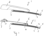
- a windscreen wiper device 1 is built up of an elastomeric wiper blade 2, in the longitudinal sides of which opposing longitudinal grooves 3 are formed, and of longitudinal strips 4 made of spring band steel, which are fitted in said longitudinal grooves 3. Said strips 4 form a flexible carrier element for the wiper blade 2, as it were, which is thus biased in a curved position (the curvature in operative position being that of a windscreen to be wiped). Neighboring ends of the strips 4 at both ends of said wiper blade 2 are interconnected by means of connecting pieces 5 or "end caps" functioning as clamping member.
- the connecting pieces 5 are each a separate constructional element, which may be form-locked ("positive locking” or “having a positive fit") or forcelocked to the ends of the strips 4.
- said connecting pieces 5 are in one piece with the strips 4 made of spring band steel. In the latter case said connecting pieces 5 form transverse bridges for the strips 4, as it were.
- the windscreen wiper device 1 is furthermore built up of a connecting device 6 of plastic material to be connected to a mounting head 7 with the interposition of an elastic flat strip-like arm 8 or "wire" made of band steel.
- the connecting device 6 may also be made of metal, such as steel or aluminum.
- the connecting device 6 comprises a first part 9 acting as a connector base having clamping members, which engage around longitudinal sides of the strips 4 that face away from each other, as a result of which first part 9 of the connecting device 6 is firmly attached to the unit consisting of the wiper blade 2 and the strips 4.
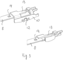
- the connecting device 6 comprises a second part 10 functioning as a joint part or "adapter” that is detachably connected to said first part 9 of said connecting device 6 by engaging cylindrical protrusions 11 of said first part 9 in co-axial cylindrical recesses 12 provided in said second part 10 of said connecting device 6 (see figures 3 and 5 ). As shown, said protrusions 11 extend outwards on either side of said first part 9.
- the first and second parts 9,10 of the connecting device 6 are snappingly and pivotally connected around a pivot axis at the location of the protrusions 11. As can be seen, the connecting device 6 is connected to said wiper blade 2 near its middle transversal plane.
- the second part 10 comprises a resilient tongue 13 extending outwardly, so that the tongue 13 engages in an identically shaped hole 14 provided in the flat strip 8.
- the connecting device 6 with the wiper blade 2 is mounted onto the mounting head 7 as follows.
- Said second part 10 can be easily slid on a free end of the flat strip 8.
- the resilient tongue 13 is initially pushed in against a spring force and then allowed to spring back into said hole 14 in said flat strip 8, thus snapping, that is clipping the resilient tongue 13 into the hole 14 of the flat strip 8.
- This is a so-called bayonet-connection.
- the windscreen wiper device 1 comprises a plastic or metallic mounting head 7 which can be fixed for rotation to a shaft 15 driven, via a mechanism not illustrated, by a small motor.
- the shaft 15 rotates alternately in a clockwise and in a counter-clockwise sense carrying the mounting head 7 into rotation also, which in turn draws the connecting device 6.
- the mounting head 7 comprises a resilient tongue 16 extending outwardly, so that the tongue 16 engages in an identically shaped hole 17 provided in the flat strip 8.
- the flat strip 8 is mounted onto the mounting head 7 as follows. Said flat strip 8 can be easily slid on another free end of the flat strip 8. During this sliding movement the resilient tongue 16 is initially pushed in against a spring force and then allowed to spring back into said hole 17 in said flat strip 8, thus snapping, that is clipping the resilient tongue 16 into the hole 17 of the flat strip 8. This is a so-called bayonet-connection. Dismounting the flat strip 8 from the mounting head 7 is thus realized by unclipping the flat strip 8 from mounting head 7.
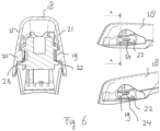
- a cap 18 is provided with inwardly extending protrusions 19,20 on opposite walls 21 of said cap 18.
- Said mounting head 7 has an at least substantially U-shaped cross-section at the location of its attachment to said arm 8, wherein each leg of said U-shaped cross-section comprises a guiding groove 22,23 cooperating with said protrusions 19,20.
- Said protrusions 19,20 each comprises a lateral rib 24 to limit a movement of a arm 8 in a direction away from a windscreen to be wiped from a wiping position into a lift(ing) position. This limitation in movement serves to not overstress the arm 8.
- the cap 18 is provided with an axis 25 extending in transverse direction and pivotally engaging into a hole 6 of the second part 10 having an open circumference.
- the cap 18 can be pivoted back towards the mounting head 7 in order to clip (“snap") the protrusions 19,20 of the cap 18 inside the guiding grooves 22,23 of the mounting head 7.
- the interconnection between the cap 18 and the mounting head 7 has a longitudinal freedom in order to lift the arm 8 into the lifting position.
Landscapes
- Engineering & Computer Science (AREA)
- Mechanical Engineering (AREA)
- Pivots And Pivotal Connections (AREA)
Claims (13)
- Scheibenwischervorrichtung (1), insbesondere für Kraftfahrzeuge, umfassend ein längliches Wischerblatt (2) aus einem flexiblen Material, das in Anlage mit einer zu wischenden Windschutzscheibe platziert werden kann, wobei das Wischerblatt (2) von dem Flachblatttyp ist und mindestens eine Nut (3) einschließt, wobei in der Nut (3) ein elastisches, längliches Trägerelement (4) angeordnet ist, wobei die Scheibenwischervorrichtung (1) ferner einen Montagekopf (7) zum Übertragen einer wechselseitigen Bewegung auf das Wischerblatt (2) umfasst, wobei die Scheibenwischervorrichtung (1) ferner einen längsverlaufenden streifenförmigen Arm (8) umfasst, wobei der Arm (8) in der Nähe eines ersten Endes davon durch einen Einrastvorgang mit dem Montagekopf (7) direkt und lösbar verbunden ist und in der Nähe eines zweiten Endes davon durch einen Einrastvorgang mit einer Verbindungsvorrichtung (6) des Wischerblattes (2) direkt und lösbar verbunden ist, und wobei der Arm (8), der aus einem elastischen Material hergestellt ist, vorgespannt ist, um einen Druck auf das Wischerblatt (2) zu der zu wischenden Windschutzscheibe hin auszuüben, wobei der Montagekopf (7) mindestens eine elastische Zunge (16) umfasst, die in ein entsprechend geformtes Loch (17) eingreift, das in dem Arm (8) in der Nähe des ersten Endes davon bereitgestellt ist, und wobei die elastische Zunge (16) zwischen einer Wischposition, die den Arm (8) auf den Montagekopf (7) hält, und einer Hebeposition, die den Arm (8) von dem Montagekopf (7) freigibt, klappbar ist, wobei eine längliche Kappe (18) mit mindestens eines von dem Montagekopf (7), dem Arm (8) und der Verbindungsvorrichtung (6) verbunden ist, und wobei der Montagekopf (7) an der Stelle seiner Befestigung an der Kappe (18) zwei gegenüberliegende Seitenwände aufweist, wobei jede Seitenwand eine Führungsnut (22,23) aufweist, die mit einem sich nach innen erstreckenden Überstand(19,20) an einer Wand (21) der Kappe (18) zusammenwirkt.
- Scheibenwischervorrichtung (1) nach Anspruch 1, wobei die Verbindungsvorrichtung (6) mindestens eine elastische Zunge (13) umfasst, die in ein entsprechend geformtes Loch (14) eingreift, das in dem Arm (8) in der Nähe des zweiten Endes davon bereitgestellt ist, und wobei die elastische Zunge (13) zwischen einer Wischposition, die das Wischerblatt (2) auf den Arm (8) hält, und einer Hebeposition, die das Wischerblatt (2) von dem Arm (8) freigibt, klappbar ist.
- Scheibenwischervorrichtung (1) nach Anspruch 2, wobei das Loch (14), das in dem Arm (8) in der Nähe des zweiten Endes davon bereitgestellt ist, einen geschlossenen Umfang aufweist.
- Scheibenwischervorrichtung (1) nach Anspruch 2 oder 3, wobei sich die elastische Zunge (13) in einer längsverlaufenden Richtung von dem Montagekopf (7) weg erstreckt.
- Scheibenwischervorrichtung (1) nach Anspruch 2, 3 oder 4, wobei wobei die Verbindungsvorrichtung (6) einen ersten Teil (9) und einen zweiten Teil (10) umfasst, wobei der Arm (8) mit dem ersten Teil (9) um die Schwenkachse schwenkbar verbunden sein kann, wobei der zweite Teil (10) zwischengeschaltet ist, wobei der zweite Teil (10) die elastische Zunge (13) umfasst, wobei der erste Teil (9) mit dem Wischerblatt (2) verbunden ist und der zweite Teil (10) mit dem ersten Teil (9) lösbar verbunden ist.
- Scheibenwischervorrichtung (1) nach Anspruch 5, wobei der zweite Teil (10) mit dem ersten Teil (9) lösbar verbunden ist, durch schwenkbares Ineingriffnehmen von Vorsprüngen (11) des ersten Teils (9) an der Stelle der Schwenkachse in Aussparungen (12), die in dem zweiten Teil (10) bereitgestellt sind.
- Scheibenwischervorrichtung (1) nach Anspruch 6, wobei der zweite Teil (10) einen im Wesentlichen U-förmigen Querschnitt aufweist, wobei eine Basis des U-förmigen Querschnitts die elastische Zunge (13) umfasst und wobei Schenkel des U-förmigen Querschnitts die Aussparungen (12) umfassen.
- Scheibenwischervorrichtung (1) nach einem der vorstehenden Ansprüche 1 bis 7, wobei das Loch (17), das in dem Arm (8) in der Nähe des ersten Endes davon bereitgestellt ist, einen geschlossenen Umfang aufweist.
- Scheibenwischervorrichtung (1) nach einem der vorstehenden Ansprüche 1 bis 8, wobei sich die elastische Zunge (16) in einer längsverlaufenden Richtung zu dem Montagekopf (7) hin erstreckt.
- Scheibenwischervorrichtung (1) nach einem der vorstehenden Ansprüche 1 bis einschließlich 9, wobei der Montagekopf (7) für eine Drehung an einer Welle (15) fixiert ist und wobei die Welle (15) abwechselnd in einem Uhrzeigersinn und gegen den Uhrzeigersinn drehbar ist, wobei der Montagekopf (7) in Drehung versetzt wird.
- Scheibenwischervorrichtung (1) nach einem der vorstehenden Ansprüche 1 bis einschließlich 9, wobei der Montagekopf (7) für eine Verschiebung an einen Schlitten fixiert ist und wobei der Schlitten abwechselnd in eine lineare Richtung und in eine andere entgegengesetzte lineare Richtung verschoben werden kann, wobei der Montagekopf (7) in Verschiebung versetzt wird.
- Scheibenwischervorrichtung (1) nach einem der vorstehenden Ansprüche 1 bis einschließlich 11, wobei der Überstand (19,20) eine seitliche Rippe (24) umfasst, um eine Bewegung eines Arms (8) in einer Richtung von einer zu wischenden Windschutzscheibe weg von einer Wischposition in eine Hebeposition zu begrenzen.
- Scheibenwischervorrichtung (1) nach einem der vorstehenden Ansprüche 1 bis einschließlich 12, wobei die Scheibenwischervorrichtung (1) ferner zwei Verbindungsstücke (5) umfasst, die jeweils in der Nähe eines Endes des Wischblatts (2) positioniert und mit einem Ende des Trägerelements (4) verbunden sind.
Priority Applications (1)
| Application Number | Priority Date | Filing Date | Title |
|---|---|---|---|
| PL18773153.4T PL3853083T3 (pl) | 2018-09-18 | 2018-09-18 | Urządzenie wycieraczkowe szyby przedniej |
Applications Claiming Priority (1)
| Application Number | Priority Date | Filing Date | Title |
|---|---|---|---|
| PCT/EP2018/075197 WO2020057729A1 (en) | 2018-09-18 | 2018-09-18 | A windscreen wiper device |
Publications (2)
| Publication Number | Publication Date |
|---|---|
| EP3853083A1 EP3853083A1 (de) | 2021-07-28 |
| EP3853083B1 true EP3853083B1 (de) | 2024-01-24 |
Family
ID=63642988
Family Applications (1)
| Application Number | Title | Priority Date | Filing Date |
|---|---|---|---|
| EP18773153.4A Active EP3853083B1 (de) | 2018-09-18 | 2018-09-18 | Scheibenwischervorrichtung |
Country Status (4)
| Country | Link |
|---|---|
| US (1) | US11577699B2 (de) |
| EP (1) | EP3853083B1 (de) |
| PL (1) | PL3853083T3 (de) |
| WO (1) | WO2020057729A1 (de) |
Families Citing this family (1)
| Publication number | Priority date | Publication date | Assignee | Title |
|---|---|---|---|---|
| WO2023165712A1 (en) * | 2022-03-04 | 2023-09-07 | Trico Belgium S.a. | A windscreen wiper device of the flat blade type |
Citations (1)
| Publication number | Priority date | Publication date | Assignee | Title |
|---|---|---|---|---|
| FR2236359A5 (en) * | 1973-07-05 | 1975-01-31 | Sev Marchal | Windscreen wiper arm assembly - articulation between drive shaft and blade arm is detachable |
Family Cites Families (10)
| Publication number | Priority date | Publication date | Assignee | Title |
|---|---|---|---|---|
| FR2382357A1 (fr) * | 1977-03-01 | 1978-09-29 | Cibie Projecteurs | Perfectionnements au montage d'essuie-glaces pour projecteurs |
| DE60314517T2 (de) | 2003-09-11 | 2008-02-07 | Federal-Mogul S.A. | Scheibenwischerarm |
| EP2103490B1 (de) * | 2008-03-20 | 2011-05-04 | Federal-Mogul S.A. | Scheibenwischvorrichtung |
| EP2621773B1 (de) * | 2010-09-30 | 2018-06-27 | Federal-Mogul S.a. | Scheibenwischervorrichtung |
| WO2012065639A1 (en) * | 2010-11-17 | 2012-05-24 | Federal-Mogul S.A. | Windscreen wiper device |
| IN2014CN04382A (de) * | 2011-11-18 | 2015-09-04 | Federal Mogul Corp | |
| DE102012112526A1 (de) * | 2012-12-18 | 2014-06-18 | Dr. Ing. H.C. F. Porsche Aktiengesellschaft | Wischerhebel eines Kraftfahrzeugscheibenwischers |
| PL3024706T3 (pl) * | 2013-07-22 | 2020-07-13 | Federal-Mogul S.A. | Urządzenie wycieraczki szyby przedniej |
| WO2016119852A1 (en) | 2015-01-29 | 2016-08-04 | Federal-Mogul S.A. | A windscreen wiper device of the flat blade type |
| US11345316B2 (en) * | 2016-02-15 | 2022-05-31 | Trico Belgium S.a. | Windscreen wiper device |
-
2018
- 2018-09-18 EP EP18773153.4A patent/EP3853083B1/de active Active
- 2018-09-18 US US17/277,332 patent/US11577699B2/en active Active
- 2018-09-18 WO PCT/EP2018/075197 patent/WO2020057729A1/en unknown
- 2018-09-18 PL PL18773153.4T patent/PL3853083T3/pl unknown
Patent Citations (1)
| Publication number | Priority date | Publication date | Assignee | Title |
|---|---|---|---|---|
| FR2236359A5 (en) * | 1973-07-05 | 1975-01-31 | Sev Marchal | Windscreen wiper arm assembly - articulation between drive shaft and blade arm is detachable |
Also Published As
| Publication number | Publication date |
|---|---|
| WO2020057729A1 (en) | 2020-03-26 |
| EP3853083A1 (de) | 2021-07-28 |
| US20210354664A1 (en) | 2021-11-18 |
| PL3853083T3 (pl) | 2024-05-13 |
| US11577699B2 (en) | 2023-02-14 |
Similar Documents
| Publication | Publication Date | Title |
|---|---|---|
| EP3416858B1 (de) | Scheibenwischervorrichtung | |
| EP2421729B2 (de) | Windschutzscheibenwischervorrichtung | |
| EP2560847B1 (de) | Scheibenwischervorrichtung | |
| EP2143602B2 (de) | Scheibenwischvorrichtung | |
| EP1514752B1 (de) | Scheibenwischerarm | |
| EP3164304B1 (de) | Scheibenwischervorrichtung | |
| WO2012065639A1 (en) | Windscreen wiper device | |
| EP3853083B1 (de) | Scheibenwischervorrichtung | |
| EP2621772B1 (de) | Scheibenwischervorrichtung | |
| EP2593340B1 (de) | Scheibenwischervorrichtung | |
| EP2585344B1 (de) | Scheibenwischervorrichtung | |
| EP1810898A1 (de) | Scheibenwischerarm | |
| WO2011026507A1 (en) | Windscreen wiper device | |
| WO2019034242A1 (en) | WIPER DEVICE | |
| US11420596B2 (en) | Windscreen wiper device | |
| CN110678365A (zh) | 风挡雨刷装置 | |
| EP3592614A1 (de) | Scheibenwischervorrichtung |
Legal Events
| Date | Code | Title | Description |
|---|---|---|---|
| STAA | Information on the status of an ep patent application or granted ep patent |
Free format text: STATUS: UNKNOWN |
|
| STAA | Information on the status of an ep patent application or granted ep patent |
Free format text: STATUS: THE INTERNATIONAL PUBLICATION HAS BEEN MADE |
|
| PUAI | Public reference made under article 153(3) epc to a published international application that has entered the european phase |
Free format text: ORIGINAL CODE: 0009012 |
|
| STAA | Information on the status of an ep patent application or granted ep patent |
Free format text: STATUS: REQUEST FOR EXAMINATION WAS MADE |
|
| 17P | Request for examination filed |
Effective date: 20210309 |
|
| AK | Designated contracting states |
Kind code of ref document: A1 Designated state(s): AL AT BE BG CH CY CZ DE DK EE ES FI FR GB GR HR HU IE IS IT LI LT LU LV MC MK MT NL NO PL PT RO RS SE SI SK SM TR |
|
| DAV | Request for validation of the european patent (deleted) | ||
| DAX | Request for extension of the european patent (deleted) | ||
| STAA | Information on the status of an ep patent application or granted ep patent |
Free format text: STATUS: EXAMINATION IS IN PROGRESS |
|
| 17Q | First examination report despatched |
Effective date: 20230217 |
|
| GRAP | Despatch of communication of intention to grant a patent |
Free format text: ORIGINAL CODE: EPIDOSNIGR1 |
|
| STAA | Information on the status of an ep patent application or granted ep patent |
Free format text: STATUS: GRANT OF PATENT IS INTENDED |
|
| INTG | Intention to grant announced |
Effective date: 20231010 |
|
| GRAS | Grant fee paid |
Free format text: ORIGINAL CODE: EPIDOSNIGR3 |
|
| GRAA | (expected) grant |
Free format text: ORIGINAL CODE: 0009210 |
|
| STAA | Information on the status of an ep patent application or granted ep patent |
Free format text: STATUS: THE PATENT HAS BEEN GRANTED |
|
| AK | Designated contracting states |
Kind code of ref document: B1 Designated state(s): AL AT BE BG CH CY CZ DE DK EE ES FI FR GB GR HR HU IE IS IT LI LT LU LV MC MK MT NL NO PL PT RO RS SE SI SK SM TR |
|
| REG | Reference to a national code |
Ref country code: GB Ref legal event code: FG4D |
|
| REG | Reference to a national code |
Ref country code: CH Ref legal event code: EP |
|
| REG | Reference to a national code |
Ref country code: IE Ref legal event code: FG4D |
|
| REG | Reference to a national code |
Ref country code: DE Ref legal event code: R096 Ref document number: 602018064520 Country of ref document: DE |
|
| REG | Reference to a national code |
Ref country code: LT Ref legal event code: MG9D |