EP3852418A1 - Verfahren und vorrichtung zur übertragung von informationen - Google Patents
Verfahren und vorrichtung zur übertragung von informationen Download PDFInfo
- Publication number
- EP3852418A1 EP3852418A1 EP19866855.0A EP19866855A EP3852418A1 EP 3852418 A1 EP3852418 A1 EP 3852418A1 EP 19866855 A EP19866855 A EP 19866855A EP 3852418 A1 EP3852418 A1 EP 3852418A1
- Authority
- EP
- European Patent Office
- Prior art keywords
- information
- network device
- terminal device
- cell
- resource
- Prior art date
- Legal status (The legal status is an assumption and is not a legal conclusion. Google has not performed a legal analysis and makes no representation as to the accuracy of the status listed.)
- Granted
Links
Images


Classifications
-
- H—ELECTRICITY
- H04—ELECTRIC COMMUNICATION TECHNIQUE
- H04B—TRANSMISSION
- H04B7/00—Radio transmission systems, i.e. using radiation field
- H04B7/02—Diversity systems; Multi-antenna system, i.e. transmission or reception using multiple antennas
- H04B7/04—Diversity systems; Multi-antenna system, i.e. transmission or reception using multiple antennas using two or more spaced independent antennas
- H04B7/08—Diversity systems; Multi-antenna system, i.e. transmission or reception using multiple antennas using two or more spaced independent antennas at the receiving station
- H04B7/0868—Hybrid systems, i.e. switching and combining
- H04B7/088—Hybrid systems, i.e. switching and combining using beam selection
-
- H—ELECTRICITY
- H04—ELECTRIC COMMUNICATION TECHNIQUE
- H04W—WIRELESS COMMUNICATION NETWORKS
- H04W16/00—Network planning, e.g. coverage or traffic planning tools; Network deployment, e.g. resource partitioning or cells structures
- H04W16/02—Resource partitioning among network components, e.g. reuse partitioning
- H04W16/10—Dynamic resource partitioning
-
- H—ELECTRICITY
- H04—ELECTRIC COMMUNICATION TECHNIQUE
- H04B—TRANSMISSION
- H04B7/00—Radio transmission systems, i.e. using radiation field
- H04B7/02—Diversity systems; Multi-antenna system, i.e. transmission or reception using multiple antennas
- H04B7/04—Diversity systems; Multi-antenna system, i.e. transmission or reception using multiple antennas using two or more spaced independent antennas
- H04B7/06—Diversity systems; Multi-antenna system, i.e. transmission or reception using multiple antennas using two or more spaced independent antennas at the transmitting station
- H04B7/0613—Diversity systems; Multi-antenna system, i.e. transmission or reception using multiple antennas using two or more spaced independent antennas at the transmitting station using simultaneous transmission
- H04B7/0615—Diversity systems; Multi-antenna system, i.e. transmission or reception using multiple antennas using two or more spaced independent antennas at the transmitting station using simultaneous transmission of weighted versions of same signal
- H04B7/0619—Diversity systems; Multi-antenna system, i.e. transmission or reception using multiple antennas using two or more spaced independent antennas at the transmitting station using simultaneous transmission of weighted versions of same signal using feedback from receiving side
- H04B7/0621—Feedback content
- H04B7/0626—Channel coefficients, e.g. channel state information [CSI]
-
- H—ELECTRICITY
- H04—ELECTRIC COMMUNICATION TECHNIQUE
- H04B—TRANSMISSION
- H04B7/00—Radio transmission systems, i.e. using radiation field
- H04B7/02—Diversity systems; Multi-antenna system, i.e. transmission or reception using multiple antennas
- H04B7/04—Diversity systems; Multi-antenna system, i.e. transmission or reception using multiple antennas using two or more spaced independent antennas
- H04B7/06—Diversity systems; Multi-antenna system, i.e. transmission or reception using multiple antennas using two or more spaced independent antennas at the transmitting station
- H04B7/0686—Hybrid systems, i.e. switching and simultaneous transmission
- H04B7/0695—Hybrid systems, i.e. switching and simultaneous transmission using beam selection
- H04B7/06952—Selecting one or more beams from a plurality of beams, e.g. beam training, management or sweeping
- H04B7/06964—Re-selection of one or more beams after beam failure
-
- H—ELECTRICITY
- H04—ELECTRIC COMMUNICATION TECHNIQUE
- H04L—TRANSMISSION OF DIGITAL INFORMATION, e.g. TELEGRAPHIC COMMUNICATION
- H04L5/00—Arrangements affording multiple use of the transmission path
- H04L5/0001—Arrangements for dividing the transmission path
- H04L5/0003—Two-dimensional division
- H04L5/0005—Time-frequency
- H04L5/0007—Time-frequency the frequencies being orthogonal, e.g. OFDM(A) or DMT
- H04L5/001—Time-frequency the frequencies being orthogonal, e.g. OFDM(A) or DMT the frequencies being arranged in component carriers
-
- H—ELECTRICITY
- H04—ELECTRIC COMMUNICATION TECHNIQUE
- H04L—TRANSMISSION OF DIGITAL INFORMATION, e.g. TELEGRAPHIC COMMUNICATION
- H04L5/00—Arrangements affording multiple use of the transmission path
- H04L5/003—Arrangements for allocating sub-channels of the transmission path
- H04L5/0048—Allocation of pilot signals, i.e. of signals known to the receiver
- H04L5/005—Allocation of pilot signals, i.e. of signals known to the receiver of common pilots, i.e. pilots destined for multiple users or terminals
-
- H—ELECTRICITY
- H04—ELECTRIC COMMUNICATION TECHNIQUE
- H04L—TRANSMISSION OF DIGITAL INFORMATION, e.g. TELEGRAPHIC COMMUNICATION
- H04L5/00—Arrangements affording multiple use of the transmission path
- H04L5/003—Arrangements for allocating sub-channels of the transmission path
- H04L5/0048—Allocation of pilot signals, i.e. of signals known to the receiver
- H04L5/0051—Allocation of pilot signals, i.e. of signals known to the receiver of dedicated pilots, i.e. pilots destined for a single user or terminal
-
- H—ELECTRICITY
- H04—ELECTRIC COMMUNICATION TECHNIQUE
- H04L—TRANSMISSION OF DIGITAL INFORMATION, e.g. TELEGRAPHIC COMMUNICATION
- H04L5/00—Arrangements affording multiple use of the transmission path
- H04L5/003—Arrangements for allocating sub-channels of the transmission path
- H04L5/0053—Allocation of signalling, i.e. of overhead other than pilot signals
- H04L5/0057—Physical resource allocation for CQI
-
- H—ELECTRICITY
- H04—ELECTRIC COMMUNICATION TECHNIQUE
- H04L—TRANSMISSION OF DIGITAL INFORMATION, e.g. TELEGRAPHIC COMMUNICATION
- H04L5/00—Arrangements affording multiple use of the transmission path
- H04L5/0091—Signalling for the administration of the divided path, e.g. signalling of configuration information
- H04L5/0092—Indication of how the channel is divided
-
- H—ELECTRICITY
- H04—ELECTRIC COMMUNICATION TECHNIQUE
- H04L—TRANSMISSION OF DIGITAL INFORMATION, e.g. TELEGRAPHIC COMMUNICATION
- H04L5/00—Arrangements affording multiple use of the transmission path
- H04L5/0091—Signalling for the administration of the divided path, e.g. signalling of configuration information
- H04L5/0094—Indication of how sub-channels of the path are allocated
-
- H—ELECTRICITY
- H04—ELECTRIC COMMUNICATION TECHNIQUE
- H04W—WIRELESS COMMUNICATION NETWORKS
- H04W24/00—Supervisory, monitoring or testing arrangements
- H04W24/04—Arrangements for maintaining operational condition
-
- H—ELECTRICITY
- H04—ELECTRIC COMMUNICATION TECHNIQUE
- H04W—WIRELESS COMMUNICATION NETWORKS
- H04W24/00—Supervisory, monitoring or testing arrangements
- H04W24/08—Testing, supervising or monitoring using real traffic
-
- H—ELECTRICITY
- H04—ELECTRIC COMMUNICATION TECHNIQUE
- H04W—WIRELESS COMMUNICATION NETWORKS
- H04W24/00—Supervisory, monitoring or testing arrangements
- H04W24/10—Scheduling measurement reports ; Arrangements for measurement reports
-
- H—ELECTRICITY
- H04—ELECTRIC COMMUNICATION TECHNIQUE
- H04W—WIRELESS COMMUNICATION NETWORKS
- H04W36/00—Hand-off or reselection arrangements
- H04W36/24—Reselection being triggered by specific parameters
- H04W36/30—Reselection being triggered by specific parameters by measured or perceived connection quality data
- H04W36/305—Handover due to radio link failure
-
- H—ELECTRICITY
- H04—ELECTRIC COMMUNICATION TECHNIQUE
- H04W—WIRELESS COMMUNICATION NETWORKS
- H04W36/00—Hand-off or reselection arrangements
- H04W36/24—Reselection being triggered by specific parameters
- H04W36/32—Reselection being triggered by specific parameters by location or mobility data, e.g. speed data
-
- H—ELECTRICITY
- H04—ELECTRIC COMMUNICATION TECHNIQUE
- H04W—WIRELESS COMMUNICATION NETWORKS
- H04W56/00—Synchronisation arrangements
- H04W56/001—Synchronization between nodes
-
- H—ELECTRICITY
- H04—ELECTRIC COMMUNICATION TECHNIQUE
- H04W—WIRELESS COMMUNICATION NETWORKS
- H04W72/00—Local resource management
- H04W72/04—Wireless resource allocation
- H04W72/044—Wireless resource allocation based on the type of the allocated resource
- H04W72/0453—Resources in frequency domain, e.g. a carrier in FDMA
-
- H—ELECTRICITY
- H04—ELECTRIC COMMUNICATION TECHNIQUE
- H04W—WIRELESS COMMUNICATION NETWORKS
- H04W72/00—Local resource management
- H04W72/04—Wireless resource allocation
- H04W72/044—Wireless resource allocation based on the type of the allocated resource
- H04W72/0457—Variable allocation of band or rate
-
- H—ELECTRICITY
- H04—ELECTRIC COMMUNICATION TECHNIQUE
- H04W—WIRELESS COMMUNICATION NETWORKS
- H04W72/00—Local resource management
- H04W72/50—Allocation or scheduling criteria for wireless resources
- H04W72/54—Allocation or scheduling criteria for wireless resources based on quality criteria
- H04W72/542—Allocation or scheduling criteria for wireless resources based on quality criteria using measured or perceived quality
-
- H—ELECTRICITY
- H04—ELECTRIC COMMUNICATION TECHNIQUE
- H04W—WIRELESS COMMUNICATION NETWORKS
- H04W76/00—Connection management
- H04W76/10—Connection setup
- H04W76/19—Connection re-establishment
-
- H—ELECTRICITY
- H04—ELECTRIC COMMUNICATION TECHNIQUE
- H04W—WIRELESS COMMUNICATION NETWORKS
- H04W76/00—Connection management
- H04W76/20—Manipulation of established connections
- H04W76/27—Transitions between radio resource control [RRC] states
-
- H—ELECTRICITY
- H04—ELECTRIC COMMUNICATION TECHNIQUE
- H04W—WIRELESS COMMUNICATION NETWORKS
- H04W80/00—Wireless network protocols or protocol adaptations to wireless operation
- H04W80/02—Data link layer protocols
-
- H—ELECTRICITY
- H04—ELECTRIC COMMUNICATION TECHNIQUE
- H04W—WIRELESS COMMUNICATION NETWORKS
- H04W16/00—Network planning, e.g. coverage or traffic planning tools; Network deployment, e.g. resource partitioning or cells structures
- H04W16/24—Cell structures
- H04W16/28—Cell structures using beam steering
-
- H—ELECTRICITY
- H04—ELECTRIC COMMUNICATION TECHNIQUE
- H04W—WIRELESS COMMUNICATION NETWORKS
- H04W24/00—Supervisory, monitoring or testing arrangements
- H04W24/02—Arrangements for optimising operational condition
-
- H—ELECTRICITY
- H04—ELECTRIC COMMUNICATION TECHNIQUE
- H04W—WIRELESS COMMUNICATION NETWORKS
- H04W36/00—Hand-off or reselection arrangements
- H04W36/0005—Control or signalling for completing the hand-off
- H04W36/0083—Determination of parameters used for hand-off, e.g. generation or modification of neighbour cell lists
-
- H—ELECTRICITY
- H04—ELECTRIC COMMUNICATION TECHNIQUE
- H04W—WIRELESS COMMUNICATION NETWORKS
- H04W56/00—Synchronisation arrangements
- H04W56/001—Synchronization between nodes
- H04W56/0015—Synchronization between nodes one node acting as a reference for the others
Definitions
- This application relates to the communications field, and more specifically, to an information transmission method and apparatus.
- Inappropriate handover (handover, HO) parameter settings adversely affect user experience.
- network resources are wasted due to a ping-pong handover, a handover failure, and a radio link failure.
- a radio link failure caused by an inappropriate handover parameter affects user experience and the network resources.
- LTE long term evolution
- radio resource management radio resource management
- MRO mobility robustness optimization
- MRO optimization is mainly used to optimize the mobility parameter, such as an offset of an A3 handover event.
- the network device determines, based on a radio link failure (radio link failure, RLF) report reported by a terminal device, a radio link failure indication (RLF indication) exchanged through an interface, and a handover report (HO report), whether the mobility parameter needs to be optimized.
- RLF radio link failure
- RLF indication radio link failure indication
- HO report handover report
- this application provides an information transmission method, to help a network device accurately perform MRO in a timely manner.
- an information transmission method includes: A first network device receives first information from a terminal device, where the first information includes information indicating that a radio link failure occurs between the terminal device and a first cell, or the first information includes information indicating that beam failure recovery occurs between the terminal device and the first cell; and the first information further includes information about a resource, and the information about the resource includes at least one of information about a beam, information about an uplink carrier, or information about a bandwidth part.
- the first network device performs mobility robustness optimization based on the first information.
- the information about the resource includes any one or more of the following: an identifier of the beam, an identifier of the uplink carrier, or an identifier of the bandwidth part.
- a beam (beam), an uplink carrier (a normal uplink carrier/a supplementary uplink carrier), and a bandwidth part (bandwidth part, BWP) are introduced into an NR system.
- a radio link failure (RLF) or a beam failure (beam failure, BF) may be caused.
- the first information includes the information indicating that the radio link failure occurs between the terminal device and the first cell, and the first information is an RLF report.
- the first information includes the information indicating that the beam failure recovery occurs between the terminal device and the first cell, and the first information is a BFR report.
- the beam includes a synchronization signal block SSB and/or a channel state information reference signal CSI-RS.
- the uplink carrier includes a normal uplink carrier and a supplementary uplink carrier.
- the terminal device may report the radio link failure report (RLF report) or the beam failure recovery report (BFR report) to the network device.
- the RLF report or the BFR report carries one or more of the information about the beam, the information about the uplink carrier, or the information about the bandwidth part. This helps the network device accurately perform MRO in a timely manner.
- the first information when the first information includes the information indicating that the beam failure recovery occurs between the terminal device and the first cell, the first information further includes at least one of a quantity of beam failures, a quantity of beam failure recovery times, or duration of the beam failure recovery.
- the first cell is a cell served by the first network device.
- the first information includes the information indicating that the beam failure recovery occurs between the terminal device and the first cell
- that the first network device performs mobility robustness optimization based on the first information includes: The first network device adjusts a configuration of the resource, or the first network device sends second information to a second network device, where the second information is used to indicate the second network device to adjust a mobility parameter.
- the first network device may be a target network device
- the second network device may be a source network device
- the first cell is a cell served by the target network device
- the terminal device is successfully handed over from the second network device to the first network device.
- the terminal device sends the first information to the first network device, and the first network device determines a cause of the BF. If the cause is a resource configuration problem, the first network device adjusts the configuration of the resource. If the cause is a downlink mobility parameter problem, the first network device may indicate the second network device to adjust a downlink mobility parameter.
- the information, about the resource, reported by the terminal device includes the information (for example, identification information) about the beam (the SSB and/or the CSI-RS).
- the first network device determines that the BF is caused by an improper threshold configuration of the beam, and that the first network device adjusts a configuration of the resource includes: The first network device adjusts a first threshold corresponding to the SSB; and/or the first network device adjusts a second threshold corresponding to the CSI-RS.
- the information, about the resource, of the terminal device includes the information (for example, identification information) about the beam and the information about the uplink carrier (for example, an identifier of the uplink carrier).
- the first network device determines that the BF is caused by improper configurations of a threshold of the beam and a threshold of the uplink carrier, and that the first network device adjusts a configuration of the resource includes: The first network device adjusts a first threshold corresponding to the SSB; and/or the first network device adjusts a second threshold corresponding to the CSI-RS; and/or the first network device adjusts a third threshold corresponding to the supplementary uplink carrier.
- the first network device may further adjust a random access channel RACH resource.
- the first cell is a cell served by the first network device.
- that a first network device receives first information from a terminal device includes: The first network device receives the first information sent by a second network device. That the first network device performs mobility robustness optimization based on the first information includes: The first network device adjusts a configuration of the resource, or the first network device sends second information to the second network device, where the second information is used to indicate the second network device to adjust a mobility parameter.
- the first network device may be a target network device
- the second network device may be a source network device
- the first cell is a cell served by the target network device
- the RLF occurs when the terminal device is handed over from the second network device to the first network device, or the RLF occurs after the terminal device is successfully handed over to the first network device.
- the terminal device After being reconnected to the second network device, the terminal device sends the first information to the second network device, the second network device forwards the first information to the first network device, and the first network device determines a cause of the RLF. If the cause is a resource configuration problem, the first network device adjusts the configuration of the resource. If the cause is a downlink mobility parameter problem, the first network device may indicate the second network device to adjust a downlink mobility parameter.
- the information, about the resource, reported by the terminal device includes the information (for example, identification information) about the beam (the SSB and/or the CSI-RS).
- the first network device determines that the RLF is caused by an improper threshold configuration of the beam, and that the first network device adjusts a configuration of the resource includes: The first network device adjusts a first threshold corresponding to the SSB; and/or the first network device adjusts a second threshold corresponding to the CSI-RS.
- the information, about the resource, of the terminal device includes the information (for example, identification information) about the beam and the information about the uplink carrier (for example, an identifier of the uplink carrier).
- the first network device determines that the RLF is caused by improper configurations of a threshold of the beam and a threshold of the uplink carrier, and that the first network device adjusts a configuration of the resource includes: The first network device adjusts a first threshold corresponding to the SSB; and/or the first network device adjusts a second threshold corresponding to the CSI-RS; and/or the first network device adjusts a third threshold corresponding to the supplementary uplink carrier.
- the first network device may further adjust a random access channel RACH resource.
- the information about the beam includes an identifier of the beam and/or measurement information of the beam, and the identifier of the beam includes a synchronization signal block SSB group number and/or a channel state information reference signal CSI-RS group number; and the information about the uplink carrier includes an identifier of the uplink carrier and/or measurement information of the uplink carrier, the identifier of the uplink carrier includes frequency information of the uplink carrier, and the uplink carrier includes a normal uplink carrier and/or a supplementary uplink carrier.
- the first network device adjusts a configuration of the resource includes any one or more of the following: The first network device adjusts a first threshold corresponding to the SSB; the first network device adjusts a second threshold corresponding to the CSI-RS; the first network device adjusts a third threshold corresponding to the supplementary uplink carrier; or the first network device adjusts a random access channel RACH resource.
- a protocol layer function of the first network device is at least one of a radio link control protocol layer function, a media access control layer function, and a physical layer function; and/or a protocol layer function of the second network device is at least one of a radio resource control protocol layer function, a service data adaptation layer function, and a packet data convergence protocol layer function.
- the first cell is a cell served by a second network device.
- the first information includes the information indicating that the beam failure recovery occurs between the terminal device and the first cell
- that a first network device receives first information from a terminal device includes: The first network device receives the first information sent by the second network device.
- That the first network device performs mobility robustness optimization based on the first information includes: The first network device adjusts a mobility parameter, or the first network device sends third information to the second network device, where the third information is used to indicate the second network device to adjust a configuration of the resource.
- the first network device may be a source network device
- the second network device may be a target network device
- the first cell is a cell served by the target network device
- the terminal device is successfully handed over from the first network device to the second network device.
- the terminal device sends the first information to the second network device
- the second network device forwards the first information to the first network device
- the first network device determines a cause of the BF. If the cause is a resource configuration problem, the first network device indicates the second network device to adjust the configuration of the resource. If the cause is a downlink mobility parameter problem, the first network device adjusts a downlink mobility parameter.
- that the first network device adjusts a mobility parameter includes: The first network device adjusts a related parameter of an A3 event.
- the first cell is a cell served by a second network device.
- the first information includes the information indicating that the radio link failure occurs between the terminal device and the first cell
- that the first network device performs mobility robustness optimization based on the first information includes: The first network device adjusts a mobility parameter, or the first network device sends third information to the second network device, where the third information is used to indicate the second network device to adjust a configuration of the resource.
- the first network device may be a source network device
- the second network device may be a target network device
- the first cell is a cell served by the target network device
- the RLF occurs when the terminal device is handed over from the first network device to the second network device, or the RLF occurs in a period of time after the terminal device is successfully handed over from the first network device to the second network device.
- the terminal device After being reconnected to the first network device, the terminal device sends the first information to the first network device, and the first network device determines a cause of the RLF. If the cause is a resource configuration problem, the first network device indicates the second network device to adjust the configuration of the resource. If the cause is a downlink mobility parameter problem, the first network device adjusts a downlink mobility parameter.
- that the first network device adjusts a mobility parameter includes: The first network device adjusts a related parameter of an A3 event.
- the method further includes: The first network device receives fourth indication information sent by the second network device, where the fourth indication information is used to indicate an adjusted configuration of the resource.
- a protocol layer function of the first network device is at least one of a radio resource control protocol layer function, a service data adaptation layer function, and a packet data convergence protocol layer function; and/or a protocol layer function of the second network device is at least one of a radio link control protocol layer function, a media access control layer function, and a physical layer function.
- an information transmission method includes: A first network device receives first information sent by a terminal device, where the first information includes information indicating that beam failure recovery occurs between the terminal device and a first cell.
- the first information is a BFR report.
- an information transmission method includes: A first network device sends first information to a second network device, where the first information includes information indicating that beam failure recovery occurs between a terminal device and a first cell.
- the first information is a BFR report.
- an information transmission method includes: A first network device sends indication information to a second network device, where the indication information is used to indicate the second network device to adjust a configuration of a resource.
- the resource includes one or more of a beam, an uplink carrier, a BWP, or a RACH resource.
- an information transmission method includes: A second network device receives indication information sent by a first network device, where the indication information is used to indicate the second network device to adjust a configuration of a resource.
- the second network device adjusts the configuration of the resource.
- the resource includes one or more of a beam, an uplink carrier, a BWP, or a RACH resource.
- that the second network device adjusts the configuration of the resource includes any one or more of the following: The second network device adjusts a first threshold corresponding to an SSB; the second network device adjusts a second threshold corresponding to a CSI-RS; the second network device adjusts a third threshold corresponding to a supplementary uplink carrier; or the second network device adjusts a random access channel RACH resource.
- an information transmission method includes: A terminal device sends first information, where the first information includes information indicating that a radio link failure occurs between the terminal device and a first cell, or the first information includes information indicating that beam failure recovery occurs between the terminal device and the first cell; and the first information further includes information about a resource, and the information about the resource includes at least one of information about a beam, information about an uplink carrier, or information about a bandwidth part.
- the first information when the first information includes the information indicating that the beam failure recovery occurs between the terminal device and the first cell, the first information further includes at least one of a quantity of beam failures, a quantity of beam failure recovery times, or duration of the beam failure recovery.
- the method before that a terminal device sends first information, the method further includes: The terminal device determines that the quantity of beam failures is greater than or equal to a first value; and/or the terminal device determines that the quantity of beam failure recovery times is greater than or equal to a second value; and/or the terminal device determines that a timer expires.
- the first value and the second value are configured by a network device.
- the information about the beam includes an identifier of the beam and/or measurement information of the beam, and the identifier of the beam includes a synchronization signal block SSB group number and/or a channel state information reference signal CSI-RS group number; and the information about the uplink carrier includes an identifier of the uplink carrier and/or measurement information of the uplink carrier, the identifier of the uplink carrier includes frequency information of the uplink carrier, and the uplink carrier includes a normal uplink carrier and/or a supplementary uplink carrier.
- the terminal device may report a radio link failure report (RLF report) or a beam failure recovery report (BFR report) to the network device.
- RLF report radio link failure report
- BFR report beam failure recovery report
- the RLF report or the BFR report carries one or more of the information about the beam, the information about the uplink carrier, or the information about the bandwidth part. This helps the network device accurately perform MRO in a timely manner.
- an information transmission apparatus is provided, and is configured to perform the method in any one of the first aspect to the fifth aspect or the possible implementations of the first aspect to the fifth aspect.
- the information transmission apparatus may include units configured to perform the method in any one of the first aspect to the fifth aspect or the possible implementations of the first aspect to the fifth aspect.
- an information transmission apparatus is provided, and is configured to perform the method in any one of the sixth aspect or the possible implementations of the sixth aspect.
- the information transmission apparatus may include units configured to perform the method in any one of the sixth aspect or the possible implementations of the sixth aspect.
- an information transmission apparatus may be the network device (the first network device or the second network device) in the foregoing method designs or a chip disposed in the network device.
- the apparatus includes a processor.
- the processor is coupled to a memory, and may be configured to execute an instruction in the memory, to implement the method in any one of the first aspect to the fifth aspect or the possible implementations of the first aspect to the fifth aspect.
- the apparatus further includes the memory.
- the apparatus further includes a communications interface, and the processor is coupled to the communications interface.
- the communications interface may be a transceiver or an input/output interface.
- the communications interface may be an input/output interface.
- the transceiver may be a transceiver circuit.
- the input/output interface may be an input/output circuit.
- an information transmission apparatus may be the terminal device in the foregoing method designs, or may be a chip disposed in the terminal device.
- the apparatus includes a processor.
- the processor is coupled to a memory, and may be configured to execute an instruction in the memory, to implement the method performed by the terminal device in any one of the sixth aspect or the possible implementations of the sixth aspect.
- the apparatus further includes the memory.
- the apparatus further includes a communications interface, and the processor is coupled to the communications interface.
- the communications interface may be a transceiver or an input/output interface.
- the communications interface may be an input/output interface.
- the transceiver may be a transceiver circuit.
- the input/output interface may be an input/output circuit.
- a program When being executed by a processor, the program is used to perform the method according to the first aspect to the sixth aspect.
- a program product includes program code.
- the program code is run by a communications unit, a processing unit, a transceiver, or a processor of an apparatus (for example, a network device or a terminal device), the apparatus is enabled to perform the method in any one of the first aspect to the sixth aspect and the possible implementations of the first aspect to the sixth aspect.
- a computer-readable medium stores a program, and the program enables an apparatus (for example, a network device or a terminal device) to perform the method in any one of the first aspect to the sixth aspect and the possible implementations of the first aspect to the sixth aspect.
- a global system for mobile communications global system for mobile communications
- code division multiple access code division multiple access
- CDMA code division multiple access
- WCDMA wideband code division multiple access
- general packet radio service general packet radio service, GPRS
- LTE long term evolution
- LTE frequency division duplex frequency division duplex
- TDD time division duplex
- UMTS universal mobile telecommunications system
- WiMAX worldwide interoperability for microwave access
- 5G future 5th generation
- new radio new radio
- a terminal device in the embodiments of this application may also be referred to as user equipment, an access terminal device, a subscriber unit, a subscriber station, a mobile station, a remote station, a remote terminal device, a mobile device, a user terminal device, a terminal device, a wireless communication device, a user agent, or a user apparatus.
- the terminal device may be a cellular phone, a cordless phone, a session initiation protocol (session initiation protocol, SIP) phone, a wireless local loop (wireless local loop, WLL) station, a personal digital assistant (personal digital assistant, PDA), a handheld device having a wireless communication function, a computing device, another processing device connected to a wireless modem, a vehicle-mounted device, a wearable device, a terminal device in a future 5G network, a terminal device in a future evolved public land mobile network (public land mobile network, PLMN), or the like.
- SIP session initiation protocol
- WLL wireless local loop
- PDA personal digital assistant
- PDA personal digital assistant
- a network device in the embodiments of this application may be a device configured to communicate with the terminal device.
- the network device may be a base transceiver station (base transceiver station, BTS) in the global system for mobile communications (global system for mobile communications, GSM) system or the code division multiple access (code division multiple access, CDMA) system, or may be a NodeB (NodeB, NB) in the wideband code division multiple access (wideband code division multiple access, WCDMA) system, or may be an evolved NodeB (evolved NodeB, eNB or eNodeB) in the LTE system, or may be a radio controller in a cloud radio access network (cloud radio access network, CRAN) scenario.
- BTS base transceiver station
- GSM global system for mobile communications
- CDMA code division multiple access
- NodeB NodeB
- WCDMA wideband code division multiple access
- eNodeB evolved NodeB
- eNB evolved NodeB
- CRAN cloud radio access
- the network device may be a relay node, an access point, a vehicle-mounted device, a wearable device, a network device in the future 5G network, a network device in the future evolved PLMN network, or the like. This is not limited in the embodiments of this application.
- the terminal device or the network device includes a hardware layer, an operating system layer running above the hardware layer, and an application layer running above the operating system layer.
- the hardware layer includes hardware such as a central processing unit (central processing unit, CPU), a memory management unit (memory management unit, MMU), and a memory (also referred to as a main memory).
- the operating system may be any one or more computer operating systems, for example, a Linux operating system, a Unix operating system, an Android operating system, an iOS operating system, or a Windows operating system, that implement service processing by using a process (process).
- the application layer includes applications such as a browser, an address book, word processing software, and instant communications software.
- a specific structure of an entity for executing a method provided in the embodiments of this application is not specifically limited in the embodiments of this application, provided that a program that records code for the method provided in the embodiments of this application can be run to perform communication according to the method provided in the embodiments of this application.
- the entity for executing the method provided in the embodiments of this application may be the terminal device, the network device, or a functional module that is in the terminal device or the network device and that can invoke and execute the program.
- aspects or features of this application may be implemented as a method, an apparatus or a product that uses standard programming and/or engineering technologies.
- the term "product" used in this application covers a computer program that can be accessed from any computer-readable component, carrier or medium.
- the computer-readable medium may include but is not limited to: a magnetic storage component (for example, a hard disk, a floppy disk or a magnetic tape), an optical disc (for example, a compact disc (compact disc, CD) and a digital versatile disc (digital versatile disc, DVD)), a smart card and a flash memory component (for example, an erasable programmable read-only memory (erasable programmable read-only memory, EPROM), a card, a stick, or a key drive).
- a magnetic storage component for example, a hard disk, a floppy disk or a magnetic tape
- an optical disc for example, a compact disc (compact disc, CD) and a digital versatile disc (digital versatile disc, DVD)
- various storage media described in this specification may indicate one or more devices and/or other machine-readable media that are configured to store information.
- machine-readable media may include but is not limited to a radio channel, and various other media that can store, contain, and/or carry an instruction and/or data.
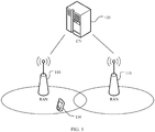
- FIG. 1 is a schematic diagram of a communications system 100 according to an embodiment of this application.
- a terminal device 130 accesses a wireless network, to obtain a service of an external network (for example, the internet) by using the wireless network, or communicate with another terminal device by using the wireless network.
- the wireless network includes a RAN 110 and a core network (CN) 120.
- the RAN 110 is configured to connect the terminal device 130 to the wireless network
- the CN 120 is configured to manage the terminal device and provide a gateway for communicating with the external network.
- the communication method provided in this application may be applicable to a wireless communications system, for example, the wireless communications system 100 shown in FIG. 1 .
- One of the two communications apparatuses may correspond to the terminal device 130 shown in FIG. 1 , for example, may be the terminal device 130 in FIG. 1 , or may be a chip configured in the terminal device 130.
- the other communications apparatus in the two communications apparatuses may correspond to the RAN 110 shown in FIG. 1 , for example, may be the RAN 110 in FIG. 1 , or may be a chip configured in the RAN 110.
- any terminal device in the wireless communications system may communicate, via a same method, with one or more network devices having a wireless communication connection with the terminal device. This is not limited in this application.
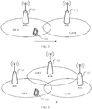
- FIG. 2 is a schematic diagram of an application scenario of a technical solution according to an embodiment of this application.
- a terminal device 131 is in a cell A served by a RAN 111.
- the terminal device 131 receives a handover command (HO command) from the RAN 111, and the command indicates the terminal device 131 to be handed over to a cell B served by a RAN 112.
- An RLF occurs before the handover is completed.
- the terminal device 131 performs cell selection and selects the cell A, and attempts to perform radio resource control (radio resource control, RRC) reestablishment.
- RRC radio resource control
- the terminal device 131 reestablishes a connection to the cell A, and after the reestablishment succeeds, the RAN 111 can identify this handover scenario as a too early handover scenario.
- a terminal device 131 is in a cell A served by a RAN 111.
- the terminal device 131 receives an HO command from the RAN 111, and the command indicates the terminal device 131 to be handed over to a cell B served by a RAN 112.
- the terminal device 131 is successfully handed over to the cell B served by the RAN 112, and the RAN 112 sends context release information to the RAN 111 and starts a timer.
- An RLF occurs within a period of time after the handover is completed.
- the terminal device 131 performs cell reselection and selects the source cell A, and then attempts to establish an RRC connection.
- the RAN 111 sends an RLF indication to the RAN 112. If the timer is still running when the RAN 112 receives the RLF indication, the RAN 112 sends a handover report (HO report) to the RAN 111, so as to indicate the RAN 111 that the handover is a premature handover.
- HO report handover report
- a terminal device 131 is in a cell A served by a RAN 111.
- the terminal device 131 receives an HO command from the RAN 111, and the command indicates the terminal device 131 to be handed over to a cell B served by a RAN 112.
- An RLF occurs before the handover is completed.
- the terminal device 131 performs cell selection and selects the cell B, and performs RRC reestablishment.
- the RAN 112 sends an RLF indication to the RAN 111, where the RLF indication includes information such as an RLF report, and the RAN 111 can identify this handover scenario as a too late handover scenario.
- a terminal device 131 is in a cell A served by a RAN 111.
- the terminal device 131 receives an HO command from the RAN 111, and the command indicates the terminal device 131 to be handed over to a cell B served by a RAN 112.
- the terminal device 131 is successfully handed over to the cell B served by the RAN 112.
- a beam failure (BF) or beam failure recovery (BFR) occurs on the terminal device in the cell B.
- the terminal device 131 may report a beam failure recovery report (BFR report) to the RAN 112, and the RAN 112 may determine a cause of the beam failure. If it is determined that the beam failure is caused by a premature handover, the RAN 112 sends a handover report (HO report) to the RAN 111, to indicate the RAN 111 that the handover is a premature handover.
- this handover scenario may be defined as another scenario, and a specific name of the another scenario is not limited in this embodiment of this application.
- FIG. 3 is another schematic diagram of an application scenario of a technical solution according to an embodiment of this application.
- a terminal device 131 receives an HO command from a RAN 111, and the command indicates the terminal device 131 to be handed over to a cell B served by a RAN 112.
- An RLF occurs before the handover is completed, and the terminal device 131 performs cell selection and selects a cell C served by a RAN 113, and performs RRC reestablishment. After an RRC is reestablished to the cell C, the RAN 113 identifies the source cell A, and then sends an RLF indication to the RAN 111.
- the RAN 111 may identify this handover scenario as a scenario of a handover to an incorrect cell.
- a terminal device 131 is in a cell A served by a RAN 111.
- the terminal device 131 receives an HO command from the RAN 111, and the command indicates the terminal device 131 to be handed over to a cell B served by a RAN 112.
- the terminal device 131 is successfully handed over to the cell B served by the RAN 112, and the RAN 112 sends context release information to the RAN 111 and starts a timer timer.
- An RLF occurs within a period of time after the handover is completed.
- the terminal device 131 performs cell reselection and selects a cell C served by a RAN 113, and performs RRC reestablishment.
- the RAN 111 After the RRC reestablishment is completed, the RAN 111 sends an RLF indication to the RAN 112. If the timer is still running when the RAN 112 receives the RLF indication, the RAN 112 sends an HO report to the RAN 111, so as to indicate the RAN 111 that the terminal device is handed over to an incorrect cell.
- FIG. 4 is a schematic diagram of a network architecture according to an embodiment of this application.
- the network architecture includes a CN device and a RAN device.
- the RAN device includes a baseband apparatus and a radio frequency apparatus.
- the baseband apparatus may be implemented by one node, or may be implemented by a plurality of nodes.
- the radio frequency apparatus may be independently implemented remotely from the baseband apparatus, or may be integrated into the baseband apparatus, or some remote parts are integrated into the baseband apparatus.
- a RAN device eNB
- the radio frequency apparatus may be remotely disposed relative to the baseband apparatus.
- a remote radio unit remote radio unit, RRU
- RRU remote radio unit
- a control plane protocol layer structure may include functions of protocol layers such as a radio resource control (radio resource control, RRC) layer, a packet data convergence protocol (packet data convergence protocol, PDCP) layer, a radio link control (radio link control, RLC) layer, a media access control (media access control, MAC) layer, and a physical layer.
- RRC radio resource control
- PDCP packet data convergence protocol
- RLC radio link control
- MAC media access control
- a user plane protocol layer structure may include functions of protocol layers such as the PDCP layer, the RLC layer, the MAC layer, and the physical layer.
- a service data adaptation protocol service data adaptation protocol, SDAP
- SDAP service data adaptation protocol
- a RAN device may include a centralized unit (centralized unit, CU) and a distributed unit (distributed unit, DU).
- a plurality of DUs may be centrally controlled by one CU.
- the CU and the DU may be divided based on a protocol layer of a wireless network. For example, functions of the PDCP layer and a protocol layer above the PDCP layer are set on the CU, and functions of protocol layers below the PDCP layer, such as the RLC layer and the MAC layer, are set on the DU.
- the RAN device may implement the functions of the protocol layers such as the RRC layer, the PDCP layer, the RLC layer, and the MAC layer by using one node. Alternatively, the RAN device may implement the functions of these protocol layers by using a plurality of nodes.
- a RAN device may include a CU and a DU, and a plurality of DUs may be centrally controlled by one CU. As shown in FIG. 4 , the CU and the DU may be divided based on a protocol layer of a wireless network. For example, functions of the PDCP layer and a protocol layer above the PDCP layer are set on the CU. For example, the CU has the functions of the PDCP layer and the RRC protocol layer. Functions of protocol layers below the PDCP layer, such as the RLC layer, the MAC layer, and the physical layer, may be set on the DU.
- Division based on the protocol layer is merely an example, and division may alternatively be performed based on another protocol layer, for example, the RLC layer. Functions of the RLC layer and protocol layers above the RLC layer are set on the CU, and functions of protocol layers below the RLC layer are set on the DU. Alternatively, division is performed at a protocol layer, for example, a portion of functions of the RLC layer and functions of protocol layers above the RLC layer are set on the CU, and remaining functions of the RLC layer and functions of protocol layers below the RLC layer are set on the DU. In addition, division may alternatively be performed in another manner, for example, the division is performed based on a latency. A function whose processing time needs to meet a latency requirement is set on the DU, and a function whose processing time does not need to meet the latency requirement is set on the CU.
- the radio frequency apparatus may not be placed in the DU but is placed remotely from the DU, or may be integrated into the DU, or a part of the radio frequency apparatus is remotely implemented and a remaining part of the radio frequency apparatus is integrated into the DU. This is not limited herein.
- FIG. 5 is a schematic diagram of another network architecture according to an embodiment of this application.
- a control plane (CP) and a user plane (UP) of a CU may be further separately implemented as different entities, and the different entities are a control plane CU entity (CU-CP entity) and a user plane CU entity (CU-UP entity).
- CU-CP entity control plane CU entity
- CU-UP entity user plane CU entity
- signaling generated by the CU may be sent to a terminal device by using a DU (for example, a DU 1 or a DU 2), or signaling generated by a terminal device may be sent to the CU by using a DU.
- a DU for example, a DU 1 or a DU 2
- signaling generated by a terminal device may be sent to the CU by using a DU.
- the DU does not parse the signaling, but directly encapsulates the signaling at a protocol layer, and transparently transmits the signaling to the terminal device or the CU.
- sending or receiving the signaling by the DU includes this scenario.
- signaling at an RRC layer or a PDCP layer is finally processed as signaling at a PHY layer and sent to the terminal device, or is converted from received signaling at a PHY layer.
- the signaling at the RRC layer or the PDCP layer may also be considered to be sent by the DU, or sent by the DU and a radio frequency apparatus.
- the CU is classified as a network device on a RAN side.
- the CU may alternatively be classified as a network device on a CN side. This is not limited herein.
- the network device may be a CU node, a DU node, or a RAN device including a CU node and a DU node.
- a beam may include a synchronization signal block (synchronization signal block, SSB) and/or a channel state information reference signal (channel state information RS, CSI-RS), and the CSI-RS may be used for random access in a non-contention scenario.
- the beam may be configured by using RRC, the SSB is sent to the terminal device by using a broadcast message, and the CSI-RS may be configured for the terminal device by using RRC dedicated signaling.
- a target base station after receiving a handover request message sent by a source base station, a target base station returns a handover request response.
- the handover request response includes a beam configuration sent to the terminal device.
- Two thresholds rsrp-ThresholdSSB and csirs-Threshold
- the thresholds are used by the terminal device to select a beam.
- the network device may configure SSB-based or CSI-RS-based measurement information for the terminal device, and the terminal device measures a reference signal received power (reference signal received power, RSRP) of the SSB or an RSRP of the CSI-RS. For example, when an RSRP obtained by the terminal device by measuring the SSB exceeds an RSRP threshold of the SSB, a preamble associated with the corresponding SSB is selected to perform random access.
- RSRP reference signal received power
- a supplementary uplink (supplementary uplink, SUL) carrier is further introduced to the NR system, that is, one cell supports one downlink carrier and two uplink carriers.
- a corresponding SUL threshold (sul-RSRP-Threshold) is also introduced.
- the terminal device determines, by comparing measured signal strength with the SUL threshold, whether to select a normal uplink (normal uplink, UL) carrier or the SUL carrier.
- whether the terminal device uses the UL or the SUL or both the UL and the SUL may be indicated by using RRC dedicated signaling.
- MRO optimization is mainly used to optimize a mobility parameter, such as an offset of an A3 handover event.
- the network device determines, based on a radio link failure (RLF) report reported by the terminal device, an RLF indication exchanged through an interface, and an HO report, whether the mobility parameter needs to be optimized.
- RLF radio link failure
- the embodiments of this application provide an information transmission method.
- a terminal device may report a radio link failure report (RLF report) or a beam failure recovery report (BFR report) to a network device.
- RLF report radio link failure report
- BFR report beam failure recovery report
- the RLF report or the BFR report carries one or more of information about a beam, information about an uplink carrier, or information about a bandwidth part. This helps the network device accurately perform MRO in a timely manner.
- FIG. 6 is a schematic flowchart of an information transmission method 200 according to an embodiment of this application.
- an execution body of the method 200 may be a network device, or may be a chip in a network device (the following uses an example in which the execution body is a network device for description).
- the method 200 includes the following steps.
- the network device receives first information from a terminal device, where the first information includes information indicating that a radio link failure occurs between the terminal device and a first cell, or the first information includes information indicating that beam failure recovery occurs between the terminal device and the first cell; and the first information further includes information about a resource, and the information about the resource includes at least one of information about a beam, information about an uplink carrier, or information about a bandwidth part.
- the first information includes the information indicating that the radio link failure occurs between the terminal device and the first cell.
- the first information is a radio link failure report (RLF report).
- RLF report radio link failure report
- the information about the resource is information about a resource used when the radio link failure occurs on the terminal device.
- the radio link failure report includes at least one of information about the radio link failure and the information about the resource used when the radio link failure occurs.
- the technical solutions in the embodiments of this application may be applied to a handover scenario, for example, to the cases of a premature handover, a delayed handover, and a handover to an incorrect cell that are shown in FIG. 2 and FIG. 3 .
- the terminal device 131 may send the RLF report to the RAN 111; or the terminal device 131 sends the RLF report to the RAN 112, and the RAN 112 sends an RLF indication to the RAN 111, so that the RAN 111 identifies this handover scenario as a premature handover scenario or a delayed handover scenario.
- FIG. 2 the terminal device 131 may send the RLF report to the RAN 111; or the terminal device 131 sends the RLF report to the RAN 112, and the RAN 112 sends an RLF indication to the RAN 111, so that the RAN 111 identifies this handover scenario as a premature handover scenario or a delayed handover scenario.
- the terminal device 131 may send an RLF report to the RAN 113, and the RAN 113 sends an RLF indication to the RAN 111, so that the RAN 111 identifies this handover scenario as a scenario of a handover to an incorrect cell.
- the technical solution in this embodiment of this application may also be applied to a single-network device scenario.
- the first cell is a cell served by a first network device
- the terminal device reestablishes an RRC connection to the first cell within a period of time after the radio link failure occurs in the first cell.
- the terminal device may send an RLF report to the first network device, and the RLF report includes information about the radio link failure and information about a resource.
- the information that is about the resource and that is recorded by the terminal device includes information about a resource being used when the RLF occurs on the terminal device, or may be information about a resource that was used (or has been used) when the RLF occurs, or may be information about a resource used for a last service when the RLF occurs, or may be information about a resource used by the terminal device before the RLF occurs.
- the information about the resource includes the information about the beam
- the information about the beam includes but is not limited to one or more of the following: an identifier of the beam, random access information of the terminal device on the beam, information about a cell to which the beam belongs (a physical cell identifier (physical cell identifier, PCI), a cell global identifier (cell global identifier, CGI), cell frequency (frequency) information of the cell, or the like), and measurement information of the terminal device on the beam (including measurement of an adjacent beam and measurement of a serving beam).
- the information about the beam further includes measurement information of the cell in which the beam is located and measurement information of a cell in which the adjacent beam is located.
- the identifier of the beam may be a beam group number (for example, an SSB-index and a CSI-RS-index).
- the information about the radio link failure includes but is not limited to one or more of the following:
- the random access information includes but is not limited to one or more of the following: a quantity of preamble attempts (number of preambles sent), preamble information used in a preamble attempt, contention indication information (contention detected), load information of a random access channel, load information of a physical uplink shared channel, maximum power reach indication information, failure duration information, access latency information, path loss estimation information, backoff time (backoff time) information, information about data available for transmission (data available for transmission), and a random access type.
- the quantity of preamble attempts may be information about a quantity of attempts to send a preamble for access that are made by the terminal device in a process from initiating preamble transmission to successfully performing random access to a network.
- the contention indication information may be information about whether contention resolution fails or whether preamble contention is detected.
- the maximum power reach indication information may be information about whether a transmitted preamble reaches a maximum power level.
- the failure duration information may be information about a time of making a random access attempt by the terminal device.
- the access latency information may be information about a time period from a moment at which the terminal device initiates preamble transmission to a moment at which random access succeeds.
- the path loss estimation information may be information about a path loss caused when the terminal device performs a random access attempt.
- the backoff time information may be information about a latency time of a network backoff control mechanism in a random access process.
- the random access type may include at least one of on demand system information (on demand system information), RRC connection establishment, and beam failure recovery (BFR).
- the random access type of the on demand system information may further include at least one of a type of a random access process message 1 (message 1, Msg1) request and a type of a random access process message 3 (message 3, Msg3) request.
- the information about the resource includes the random access information
- the random access information includes information about a beam used when random access fails and/or information about a beam used when random access succeeds.
- the information about the resource includes the information about the uplink carrier, and in description similar to that of the information about the beam, the identifier of the beam may be replaced with an identifier of the uplink carrier.
- the identifier of the uplink carrier may be any one or more of frequency information of the uplink carrier, the identifier of the uplink carrier, and the like, and the uplink carrier may be an SUL or a UL.
- the information about the uplink carrier is information about an uplink carrier used when the RLF occurs on the terminal device, or may be information about an uplink carrier used before the RLF occurs on the terminal device.
- the information about the resource includes the information about the bandwidth part, and in description similar to that of the information about the beam, the identifier of the beam is replaced with an identifier of the BWP.
- the information about the BWP may further include any one or more of the following: a location and a bandwidth (location and bandwidth), a subcarrier spacing (subcarrier spacing), used information of an uplink BWP, and used information of a downlink BWP.
- the used information of the uplink or downlink BWP may include any one or more of the following: a common configuration, a dedicated configuration, and the like.
- the information about the bandwidth part is information about a bandwidth part used when the RLF occurs on the terminal device, or may be information about a bandwidth part used before the RLF occurs on the terminal device.
- the first information may be sent to the network device by using an existing RLF report, or may be sent to the network device by using a reestablishment request message, or may be sent by using another existing message or report, or may be sent by using a new report or message.
- the reestablishment request message may include at least one type of information or a combination of a plurality of types of information in the first information. This is not limited in this application.
- the first information includes information indicating that a beam failure occurs between the terminal device and the first cell.
- the first information is a beam failure recovery report (BFR report), and the BFR report includes information about the beam failure and the information about the resource.
- BFR report includes information about the beam failure and the information about the resource.
- the terminal device 131 may send the BFR report to the RAN 112, and the RAN 112 performs MRO after determining a cause of the beam failure.
- the first cell is a cell served by the first network device
- a BF occurs on the terminal device in the first cell and BFR succeeds
- the terminal device may send a BFR report to the first network device.
- the BFR report includes information about the beam failure and information about a resource.
- the information that is about the resource and that is recorded by the terminal device includes information about a resource used when the BFR/BF occurs on the terminal device, or may be information about a resource that was used (or has been used) when the BFR/BF occurs, or may be information about a resource used for a last service when the BFR/BF occurs, or may be information about a resource used by the terminal device before the BFR/BF occurs.
- description of information about a beam, information about an uplink carrier, and information about a bandwidth part that are included in the information about the resource is similar to the foregoing description. For brevity, details are not described herein again.
- the information about the beam failure includes but is not limited to one or more of the following:
- the first information further includes at least one of a quantity of beam failures, a quantity of beam failure recovery times, or duration of the beam failure recovery.
- the at least one of the quantity of beam failures, the quantity of beam failure recovery times, or the duration of the beam failure recovery may alternatively be directly included in the BFR report.
- S220 The network device performs mobility robustness optimization based on the first information.
- the network device may perform mobility robustness optimization.
- the first network device may be a target network device, or may be a source network device. The following describes in detail a specific optimization process of the network device in a handover scenario with reference to FIG. 7 to FIG. 19 .
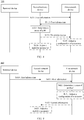
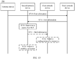
- FIG. 7 is a schematic flowchart of an information transmission method 300 according to an embodiment of this application. As shown in FIG. 7 , the method 300 includes the following steps.
- a terminal device sends first information to a first network device, and the first network device receives the first information sent by the terminal device, where the first information includes information indicating that beam failure recovery occurs between the terminal device and a first cell.
- the method 300 further includes: A second network device sends a handover command to the terminal device, and the terminal device receives the handover command sent by the second network device, where the handover command is used to indicate the terminal device to be handed over from a second cell served by the second network device to the first cell served by the first network device.
- the terminal device is handed over from the second cell served by the second network device to the first cell served by the first network device.
- a beam failure occurs on the terminal device in the first cell, and the beam failure recovery succeeds.
- the first network device may be a target network device
- the second network device may be a source network device
- the first cell is a target cell served by the target network device
- the second cell is a source cell served by the source network device
- the terminal device may report the first information to the first network device.
- the terminal device 131 receives the handover command sent by the source cell A, and the terminal device 131 performs random access (RACH) to the target cell B and successfully accesses the cell B.
- RACH random access
- the BFR occurs for a plurality of times in a short period of time (for example, less than 3 s) after the terminal device 131 successfully accesses the target cell B, and the recovery succeeds. Although the recovery succeeds, signal quality and the like of the terminal device in the cell B may not be very good. In this case, the terminal device 131 triggers reporting of the BFR report.
- the method further includes: The terminal device determines that a quantity of BFs is greater than or equal to a first value; and/or
- the first value, the second value, and the timer may be configured by a network device for the terminal device, or specified in a protocol, or determined in another manner. This is not limited in this application.
- the reporting of the first information may be triggered by the terminal device in an event trigger manner, where for example, an event is that the quantity of BFs or the quantity of BFR times is greater than or equal to a value, or may be triggered in a timer (timer) trigger manner.
- the first value and the second value in the event trigger manner and the timer may be configured by the network device (for example, the target network device) for the terminal device.
- the first information is a BFR report.
- the BFR report may be reported through an RRC connection between the terminal device and the first network device, or may be reported by using another existing message, or may be reported by using a newly defined message. This is not limited in this embodiment of this application.
- S320 The first network device determines a cause of the beam failure.
- that the first network device determines a cause of the beam failure includes: The first network device determines that the beam failure is caused by an improper configuration of a resource.
- the method 300 further includes the following step: S331: The first network device adjusts the configuration of the resource.
- the resource includes one or more of a beam, an uplink carrier, or a bandwidth part
- that the first network device adjusts the configuration of the resource includes any one or more of the following: The first network device adjusts a first threshold corresponding to an SSB;
- the method 300 further includes: The first network device sends fourth information to the second network device, and the second network device receives the fourth information sent by the first network device, where the fourth information is used to indicate an adjusted configuration of the resource.
- that the first network device determines a cause of the beam failure includes: The first network device determines that the beam failure is caused by an improper configuration of a mobility parameter.
- the first network device directly determines that the beam failure is caused by a scenario such as a premature handover scenario or a delayed handover scenario.
- the method 300 further includes the following steps:
- the second network device adjusts the mobility parameter includes: The second network device adjusts a related parameter of an A3 event.
- the second network device determines, based on the second information, whether the beam failure is caused by the improper configuration of the mobility parameter, that is, determines whether the beam failure is caused by the scenario such as the premature handover scenario or the delayed handover scenario, so as to adjust the mobility parameter.
- the second information is an indication indicating the premature handover
- the second network device adjusts the mobility parameter after receiving the second information.
- the first network device determines that the beam failure is caused by a resource configuration problem
- the first network device adjusts the configuration of the resource, for example, adjusts related threshold configurations of a beam and an SUL, for a subsequent handover configuration. Otherwise, if the first network device determines that the beam failure is not caused by the resource configuration problem, the first network device sends an indication to the second network device. After receiving the indication, the second network device determines that the beam failure is caused by the premature handover scenario or another newly defined scenario, so as to adjust a related mobility parameter.
- a process in which the network device performs mobility robustness optimization in S210 in the method 200 may include S320 and S331, or may include S320, S332, and S333.
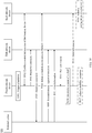
- FIG. 8 is another schematic flowchart of an information transmission method 300 according to an embodiment of this application.
- a difference between the method shown in FIG. 7 and the method shown in FIG. 8 lies in that, the cause of the beam failure in the method shown in FIG. 7 may be determined by the target network device (the first network device), and a cause of a beam failure in the method shown in FIG. 8 may be determined by a source network device (a second network device).
- the method 300 includes the following steps.
- a terminal device sends first information to a first network device, and the first network device receives the first information sent by the terminal device, where the first information includes information indicating that beam failure recovery occurs between the terminal device and a first cell.
- S311 is the same as S310. For brevity, details are not described herein again.
- S312 The first network device sends the first information to the second network device, and the second network device receives the first information sent by the first network device.
- the first network device forwards the first information to the second network device, and the second network device determines the cause of the beam failure.
- S321 The second network device determines the cause of the beam failure.
- the second network device determines the cause of the beam failure includes: The second network device determines that the beam failure is caused by an improper configuration of a resource.
- the method 300 further includes the following steps:
- the resource includes one or more of a beam, an uplink carrier, or a bandwidth part
- that the first network device adjusts the configuration of the resource includes any one or more of the following: The first network device adjusts a first threshold corresponding to SSB;
- the third information is used to indicate a configuration, of a specific resource, to be adjusted by the first network device, and the specific resource is one or more of a beam, an uplink carrier, or a bandwidth part.
- that the second network device determines the cause of the beam failure includes: The second network device determines that the beam failure is caused by an improper configuration of a mobility parameter.
- the second network device directly determines that the beam failure is caused by a scenario such as a premature handover scenario or a delayed handover scenario.
- the method 300 further includes the following step: S336: The second network device adjusts the mobility parameter.
- the second network device determines that the beam failure is caused by the improper configuration of the mobility parameter, the second network device determines a handover problem (for example, a premature handover or a delayed handover) and adjusts the mobility parameter.
- a handover problem for example, a premature handover or a delayed handover
- the second network device determines that the beam failure is caused by a resource configuration problem
- the second network device indicates the first network device to adjust the configuration of the resource, for example, adjusts related threshold configurations of a beam and an SUL, for a subsequent handover configuration. Otherwise, the second network device determines that the beam failure is not caused by the resource configuration problem but a mobility parameter problem, so that the second network device determines that the beam failure is caused by a premature handover scenario or another newly defined scenario, so as to adjust a related mobility parameter.
- information reported by the terminal device carries information about the resource. This helps a network device accurately perform mobility robustness optimization in a timely manner, thereby avoiding a handover failure and improving a handover success rate.
- FIG. 9 is a schematic flowchart of an information transmission method 400 according to an embodiment of this application. As shown in FIG. 9 , the method 400 includes the following steps.
- a terminal device sends first information to a second network device, and the second network device receives the first information sent by the terminal device, where the first information includes information indicating that a radio link failure occurs between the terminal device and a first cell.
- the second network device sends the first information to a first network device, and the first network device receives the first information sent by the second network device.
- the method 400 further includes: The second network device sends a handover command to the terminal device, and the terminal device receives the handover command sent by the second network device, where the handover command is used to indicate the terminal device to be handed over from a second cell served by the second network device to the first cell served by the first network device.
- the terminal device determines that the radio link failure occurs before the terminal device is handed over to the first cell served by the first network device, or the terminal device determines that the radio link failure occurs after the terminal device is handed over to the first cell served by the first network device.
- the terminal device is reconnected to the second cell served by the second network device.
- the first network device may be a target network device
- the second network device may be a source network device
- the first cell is a target cell served by the target network device
- the second cell is a source cell served by the source network device.
- the terminal device 131 receives the handover command sent by the source cell A, and the terminal device 131 performs random access (RACH) to the target cell B.
- RACH random access
- the RLF occurs in a random access process, and the terminal device 131 is reconnected to the source cell A.
- the terminal device 131 triggers reporting of an RLF report to the RAN 111.
- the terminal device 131 does not send an RLF report to the RAN 111, and the terminal device 131 directly sends a reestablishment request to the RAN 111.
- the terminal device 131 receives the handover command sent by the source cell A, and the terminal device 131 performs random access (RACH) to the target cell B and successfully accesses the cell B.
- RACH random access
- the RLF occurs in a short period of time (for example, less than 3s) after the terminal device 131 successfully accesses the target cell B.
- the terminal device 131 triggers reporting of an RLF report to the RAN 111, and the RAN 111 forwards the RLF report to the RAN 112.
- the RLF may be caused by a BFR recovery failure, or may be caused by improper configurations of a UL and an SUL, or may be caused by an improper configuration of a RACH resource, or may be caused by another existing cause. This is not limited in this application.
- BFR occurs on the terminal device in the target cell B, but the recovery fails, resulting in an RLF and RRC connection reestablishment to a source cell A.
- a configuration of a UL/SUL or a configuration of a RACH resource of the target cell B is improper, and consequently, a terminal device cannot successfully access the target cell B, resulting in an RLF and RRC connection reestablishment to a source cell A.
- the first information is an RLF report.
- the RLF report may be reported through an RRC connection between the terminal device and the first network device, or may be reported by using another existing message, or may be reported by using a newly defined message. This is not limited in this embodiment of this application.
- S420 The first network device determines a cause of the radio link failure.
- that the first network device determines a cause of the radio link failure includes: The first network device determines that the radio link failure is caused by an improper configuration of a resource.
- the method 400 further includes the following step: S431: The first network device adjusts the configuration of the resource.
- the resource includes one or more of a beam, an uplink carrier, or a bandwidth part
- that the first network device adjusts the configuration of the resource includes any one or more of the following: The first network device adjusts a first threshold corresponding to SSB;
- that the first network device determines a cause of the radio link failure includes: The first network device determines that the beam failure is caused by an improper configuration of a mobility parameter.
- the method 400 further includes the following steps:
- S420 to S433 are similar to S320 to S333 in the method 300 in FIG. 6 .
- S420 to S433 are similar to S320 to S333 in the method 300 in FIG. 6 .
- details are not described herein again.
- FIG. 10 is another schematic flowchart of an information transmission method 400 according to an embodiment of this application.
- a difference between the method shown in FIG. 9 and the method shown in FIG. 10 lies in that, the cause of the radio link failure in the method shown in FIG. 9 may be determined by the target network device (the first network device), and a cause of a radio link failure in the method shown in FIG. 10 may be determined by a source network device (a second network device).
- the method 400 includes the following steps.
- a terminal device sends first information to the second network device, and the second network device receives the first information sent by the terminal device, where the first information includes information indicating that a radio link failure occurs between the terminal device and a first cell.
- the second network device may not forward the first information to a first network device.
- S421 The second network device determines a cause of the radio link failure.
- that the second network device determines a cause of the radio link failure includes: The second network device determines that the radio link failure is caused by an improper configuration of a resource.
- the method 400 further includes the following steps:
- the third information is used to indicate a configuration, of a specific resource, to be adjusted by the first network device, and the specific resource is one or more of a beam, an uplink carrier, or a bandwidth part.
- that the second network device determines a cause of the radio link failure includes: The second network device determines that the beam failure is caused by an improper configuration of a mobility parameter.
- the method 400 further includes the following step: S436: The second network device adjusts the mobility parameter.
- FIG. 11 is a schematic flowchart of an information transmission method 500 according to an embodiment of this application. As shown in FIG. 11 , the method 500 includes the following steps.
- a terminal device sends first information to a first network device, and the first network device receives the first information sent by the terminal device, where the first information includes information indicating that a radio link failure occurs between the terminal device and a first cell.
- the first network device may be a target network device
- a second network device may be a source network device
- the first cell is a cell served by the target network device
- a second cell is a cell served by the source network device.
- the radio link failure occurs in the second cell before the terminal device receives a handover command, the terminal device reestablishes a connection to the first cell, and the terminal device may report the first information to the first network device.
- the RLF occurs in the cell A before the terminal device 131 receives the handover command sent by the source cell A, and the terminal device 131 reselects the target cell B in the RAN 112. In this case, the terminal device 131 triggers reporting of an RLF report.
- the first information is an RLF report.
- S520 The first network device determines a cause of the radio link failure.
- S520 is similar to S420 to S433 in FIG. 8 .
- S420 is similar to S420 to S433 in FIG. 8 .
- details are not described herein again.
- the second network device may determine the cause of the radio link failure.
- the method 500 further includes the following steps:
- S521 and S522 are similar to S421 to S436 in FIG. 9 .
- S521 and S522 are similar to S421 to S436 in FIG. 9 .
- details are not described herein again.
- FIG. 12 is a schematic flowchart of an information transmission method 600 according to an embodiment of this application. As shown in FIG. 12 , the method 600 includes the following steps.
- a terminal device sends first information to a second network device, and the second network device receives the first information sent by the terminal device, where the first information includes information indicating that a beam failure occurs between the terminal device and a second cell.
- a first network device may be a target network device
- the second network device may be a source network device
- the second cell is a cell served by the source network device. If the beam failure occurs on the terminal device in the second cell and beam failure recovery succeeds, for example, if beam failures frequently occur in the second cell before the terminal device receives a handover command, and beam failure recovery succeeds, the terminal device may report the first information to the second network device.
- the terminal device 131 may report a BFR report to the RAN 111.
- S620 The second network device determines a cause of the beam failure.
- the second network device determines that the beam failure is caused by an improper configuration of a resource.
- the method 600 further includes the following step: S631: The second network device adjusts the configuration of the resource.
- the second network device determines the cause of the beam failure.
- the second network device determines that the beam failure is caused by an improper configuration of a mobility parameter.
- the method 600 further includes the following step: S632: The second network device adjusts the mobility parameter.
- the second network device may determine whether the beam failure is caused by a resource configuration problem. If the second network device determines that the beam failure is caused by the resource configuration problem, the second network device adjusts the configuration of the resource, for example, adjusts related threshold configurations of a beam and an SUL. Optionally, the second network device may alternatively perform determining based on measurement quality of a neighboring cell in the report. If signal strength of the neighboring cell is relatively good (for example, the signal strength of the neighboring cell is better than that of a serving cell, but a handover event is not satisfied), the second network device determines that the beam failure is caused by a delayed handover scenario or another newly defined scenario, so as to adjust a related downlink mobility parameter.
- the information transmission method in this embodiment of this application when the beam failure occurs, information reported by the terminal device carries the information about the resource. This helps a network device accurately perform mobility robustness optimization in a timely manner, thereby avoiding a handover failure and improving a handover success rate.
- FIG. 13 is a schematic flowchart of an information transmission method 700 according to an embodiment of this application. As shown in FIG. 13 , the method 700 includes the following steps.
- a terminal device sends first information to a third network device, and the third network device receives the first information sent by the terminal device, where the first information includes information indicating that a radio link failure occurs between the terminal device and a first cell.
- the third network device sends the first information to a second network device, and the second network device receives the first information sent by the third network device.
- the second network device may be the RAN 111 in FIG. 3
- the third network device may be the RAN 113 in FIG. 3 .
- the terminal device 131 receives a handover command sent by the RAN 111, and the command indicates the terminal device 131 to be handed over from the cell A to the cell B.
- the RLF occurs before the handover is completed, and the terminal device performs cell reselection and reselects the cell C served by the RAN 113.
- the terminal device 131 reports an RLF report to the RAN 113, and the RAN 113 identifies that the RLF occurs on the terminal device 131 in the cell A.
- the RAN 113 sends an RLF indication to the RAN 111, so that the RAN 111 records that the terminal device 131 is handed over to an incorrect cell once.
- S720 The second network device determines a cause of the radio link failure.
- that the second network device determines a cause of the radio link failure includes: The second network device determines that the radio link failure is caused by an improper configuration of a resource.
- the method 700 further includes the following steps:
- a method for adjusting the configuration of the resource by the first network device may be the same as the method in the method 300.
- details are not described herein again.
- that the second network device determines a cause of the radio link failure includes: The second network device determines that the radio link failure is caused by an improper configuration of a mobility parameter.
- the method 700 further includes the following step: S733: The second network device adjusts the mobility parameter.
- the terminal device is handed over to an incorrect cell after a beam failure occurs, and information reported by the terminal device carries information about the resource. This helps a network device accurately perform mobility robustness optimization in a timely manner, thereby avoiding a handover failure and improving a handover success rate.
- FIG. 14 is a schematic flowchart of an information transmission method 800 according to an embodiment of this application. As shown in FIG. 14 , the method 800 includes the following steps.
- a terminal device sends first information to a third network device, and the third network device receives the first information sent by the terminal device, where the first information includes information indicating that a beam failure occurs between the terminal device and a first cell.
- the third network device sends the first information to a first network device, and the first network device receives the first information sent by the third network device.
- the first network device may be the RAN 112 in FIG. 3
- the third network device may be the RAN 113 in FIG. 3 .
- the terminal device 131 receives a handover command sent by the RAN 111, the command indicates the terminal device 131 to be handed over from the cell A to the cell B, and the terminal device 131 is successfully handed over to the cell B.
- the RLF occurs within a period of time after the handover succeeds, and the terminal device performs cell reselection and reselects the cell C served by the RAN 113.
- the terminal device 131 reports an RLF report to the RAN 113, and the RAN 113 identifies that the RLF occurs on the terminal device 131 in the cell B.
- the RAN 113 sends an RLF indication to the RAN 112, so that the RAN 112 records that the terminal device 131 is handed over to an incorrect cell once.
- S820 The first network device determines a cause of a radio link failure.
- that the first network device determines a cause of a radio link failure includes: The first network device determines that the radio link failure is caused by an improper configuration of a resource.
- the method 800 further includes the following step: S831: The first network device adjusts the configuration of the resource.
- a method for adjusting the configuration of the resource by the first network device may be the same as the method in the method 300.
- details are not described herein again.
- the first network device determines a cause of a radio link failure includes: The first network device determines that the radio link failure is caused by an improper configuration of a mobility parameter.
- the method 800 further includes the following steps:
- the terminal device is handed over to an incorrect cell after the beam failure occurs, and information reported by the terminal device carries information about the resource. This helps a network device accurately perform mobility robustness optimization in a timely manner, thereby avoiding a handover failure and improving a handover success rate.
- the foregoing describes in detail, with reference to FIG. 6 to FIG. 14 , a mechanism in which a network device performs MRO when a BF or an RLF occurs on a terminal device in a scenario of a premature handover, a delayed handover, and a handover to an incorrect cell.
- the following describes an information transmission method 900 to an information transmission method 1100 in the embodiments of this application with reference to the accompanying drawings, and the method 900 to the method 1100 describe a mechanism in which a network device performs MRO when a network device is divided into a CU and a DU.
- FIG. 15 is a schematic flowchart of an information transmission method 900 according to an embodiment of this application. As shown in FIG. 15 , the method 900 includes the following steps.
- a terminal device sends first information to a fourth network device through a fifth network device, and the fourth network device receives the first information from the terminal device, where the first information includes information indicating that a radio link failure occurs between the terminal device and a first cell.
- the method further includes the following steps:
- the handover command is RRC reconfiguration information.
- the first information is carried in the reestablishment request information.
- the method 900 may also be applicable to a case in which the terminal device successfully initiates the random access process to the sixth network device, but the RLF occurs on the sixth network device, and the terminal device reselects the fifth network device (where a reestablishment message may carry a PCI of the first cell).
- the fourth network device determines that the handover may be triggered based on an A3 measurement event.
- the first cell is a cell served by the sixth network device.
- the fourth network device has at least one of a radio resource control protocol layer function, a service data adaptation layer function, and a packet data convergence protocol layer function; and/or
- the first information is an RLF report.
- the fourth network device may be the CU in FIG. 4 , or may be the CU-CP or the CU-UP in FIG. 5 .
- the fifth network device may be the DU 1 in FIG. 4 , or the DU 1 in FIG. 5 .
- the sixth network device may be the DU 2 in FIG. 4 , or the DU 2 in FIG. 5 .
- one CU may communicate with a plurality of DUs, and the CU may trigger a DU change.
- the CU may communicate with the terminal device through the DU 1, and the CU may change the DU, so that the CU communicates with the terminal device through the DU 2.
- An RLF occurs in a random access process between the terminal device and the target DU 2, the terminal device reselects the source DU 1 and accesses the CU, and the terminal device may carry a PCI of a failed cell in a message reported to the CU.
- the RLF report may be sent to the CU when the terminal device and the DU 1 reestablish a connection to the CU, or may be directly sent to the CU.
- Content of the RLF report is the same as that described in the foregoing embodiments. For brevity, details are not described herein again.
- S920 The fourth network device sends the first information to the sixth network device, and the sixth network device receives the first information sent by the fourth network device.
- the fourth network device sends the first information to the sixth network device by using a new message (for example, by using F1AP radio link failure indication (RLF indication) information) or an existing message.
- a new message for example, by using F1AP radio link failure indication (RLF indication) information
- RLF indication radio link failure indication
- the existing message may be an F1AP message, and includes but is not limited to the following messages: a terminal device context setup request/response (UE context setup request/response) message, a terminal device context modification request/response/acknowledgment (UE context modification request/response/required) message, a terminal device context release request/response (UE context release request/response) message, or an F1 interface setup request/response (F1 setup request/response) message.
- UE context setup request/response UE context setup request/response
- UE context modification request/response/acknowledgment UE context modification request/response/required
- UE context release request/response UE context release request/response
- F1 interface setup request/response F1 setup request/response
- the sixth network device determines a cause of the radio link failure.
- that the sixth network device determines a cause of the radio link failure includes: The sixth network device determines that the radio link failure is caused by an improper configuration of a resource.
- the method 900 further includes the following step: S931: The sixth network device adjusts the configuration of the resource.
- the DU 2 determines a problem such as a problem of a RACH resource configuration, a beam configuration, or an SUL/UL configuration based on content of the RLF report. If the problem is a resource configuration problem, the DU 2 directly modifies the configuration.
- a method for adjusting the configuration of the resource by the sixth network device may be the same as the method in the method 300.
- details are not described herein again.
- that the sixth network device determines a cause of the radio link failure includes: The sixth network device determines that the radio link failure is caused by an improper configuration of a mobility parameter.
- the method 900 further includes the following steps: S932: The sixth network device sends second information to the fourth network device, and the fourth network device receives the second information sent by the sixth network device, where the second information is used to indicate the fourth network device to adjust the mobility parameter.
- the second information may be further used to indicate that the sixth network device has completed resource configuration modification, or used to indicate a mobility problem, for example, a problem of a premature handover or a delayed handover.
- S933 The fourth network device adjusts the mobility parameter.
- the DU 2 may send a DU change report to the CU, where the report includes information indicating whether the problem is a configuration problem, configuration modification completion information or information indicating whether the problem is a premature handover problem, or the like. That is, if the problem is not the resource configuration problem of the DU 2, the DU change report sent by the DU 2 indicates that the problem is a premature handover problem, so that the CU optimizes a downlink mobility parameter. Alternatively, if the problem is the resource configuration problem of the DU 2, the DU change report sent by the DU 2 indicates that the resource configuration modification of the DU 2 has been completed.
- the DU change report is sent by using a newly defined F1AP message or an existing F1AP message.
- FIG. 16 is another schematic flowchart of an information transmission method 900 according to an embodiment of this application. As shown in FIG. 16 , the method 900 includes the following steps.
- a terminal device sends first information to a fourth network device through a fifth network device, and the fourth network device receives the first information sent by the terminal device, where the first information includes information indicating that a radio link failure occurs between the terminal device and a first cell.
- the fourth network device determines a cause of the radio link failure.
- that the fourth network device determines a cause of the radio link failure includes: The fourth network device determines that the radio link failure is caused by an improper configuration of a resource.
- the method 900 further includes the following steps:
- the third information is used to indicate a configuration, of a specific resource, to be adjusted by the sixth network device, and the specific resource is one or more of a beam, an uplink carrier, or a bandwidth part.
- a DU 2 modifies a configuration of a corresponding resource based on an indication of the third information.
- a method for adjusting the configuration of the resource by the sixth network device may be the same as the method in the method 300.
- details are not described herein again.
- a CU determines a problem based on an RLF report, for example, determines that the problem is a premature handover problem of the DU 2 or a configuration problem of the DU 2.
- the configuration problem may include a problem of at least one of a RACH resource configuration, a beam configuration, a bandwidth part BWP configuration, an SUL/UL configuration, and the like. If the problem is a resource configuration problem, the CU sends a problem indication to the DU 2.
- the problem indication may be a RACH resource configuration problem indication, a beam problem indication, a BWP configuration problem indication, an SUL/UL configuration problem indication, or the like. Therefore, the DU 2 modifies a corresponding resource configuration.
- the DU 2 may send a DU change report to the CU, where the report includes information indicating whether the problem is a configuration problem, configuration modification completion information, and the like.
- that the fourth network device determines a cause of the radio link failure includes: The fourth network device determines that the radio link failure is caused by an improper configuration of a mobility parameter.
- the method 900 further includes the following step: S937: The fourth network device adjusts the downlink mobility parameter.
- the CU directly optimizes the downlink mobility parameter.
- the optimized downlink mobility parameter includes a related parameter of an A3 event.
- FIG. 17 is a schematic flowchart of an information transmission method 1000 according to an embodiment of this application. As shown in FIG. 17 , the method 1000 includes the following steps.
- a terminal device sends first information to a fourth network device, and the fourth network device receives the first information sent by a sixth network device, where the first information includes information indicating that a beam failure occurs between the terminal device and a first cell.
- a terminal device sends first information to a fourth network device includes: The terminal device directly sends the first information to the fourth network device.
- the terminal device sends the first information to the fourth network device through the sixth network device.
- the first information includes a BFR report.
- the method further includes the following steps:
- the handover command is RRC reconfiguration information.
- S1004 The terminal device successfully initiates a random access process to the sixth network device, but BFR occurs for a plurality of times on the terminal device in the first cell and no RLF occurs.
- the method further includes: The terminal device determines that a quantity of BFs is greater than or equal to a first value; and/or
- the reporting of the first information may be triggered by the terminal device in an event trigger manner, where for example, an event is that the quantity of BFs or the quantity of BFR times is greater than or equal to a value, or may be triggered in a timer (timer) trigger manner.
- the first value and the second value in the event trigger manner and the timer may be configured by a network device (for example, a CU) for the terminal device.
- the first cell is a cell served by the sixth network device.
- the fourth network device has at least one of a radio resource control protocol layer function, a service data adaptation layer function, and a packet data convergence protocol layer function; and/or
- the fourth network device may be the CU in FIG. 4 , or may be the CU-CP or the CU-UP in FIG. 5 .
- the fifth network device may be the DU 1 in FIG. 4 , or the DU 1 in FIG. 5 .
- the sixth network device may be the DU 2 in FIG. 4 , or the DU 2 in FIG. 5 .
- the CU triggers a DU handover, and then the CU and the target DU 2 establish a context of the terminal device.
- the CU sends a handover command (for example, RRC reconfiguration information) to the terminal device through the source DU 1, so that the terminal device performs random access to the target DU 2, and the terminal device successfully performs random access to the DU 2.
- a handover command for example, RRC reconfiguration information
- the terminal device records and sends a BFR report to the CU.
- the BFR report of the terminal device is directly reported to the CU (for example, by using an RRC message), or is first reported to the DU 2 (for example, by using a layer 1 message or a layer 2 message) and then is sent to the CU through the DU 2.
- S1020 The fourth network device sends the first information to the sixth network device, and the sixth network device receives the first information sent by the fourth network device.
- the fourth network device sends the first information to the sixth network device by using a new message (for example, a newly defined F1AP beam failure recovery indication (BFR indication) message) or an existing F1AP message.
- a new message for example, a newly defined F1AP beam failure recovery indication (BFR indication) message
- BFR indication beam failure recovery indication
- the existing F1AP message includes but is not limited to the following messages: a terminal device context setup request/response (UE context setup request/response) message, a terminal device context modification request/response/acknowledgment (UE context modification request/response/required) message, a terminal device context release request/response (UE context release request/response/required) message, or an F1 interface setup request/response (F1 setup request/response) message.
- UE context setup request/response UE context setup request/response
- UE context modification request/response/acknowledgment UE context modification request/response/required
- UE context release request/response UE context release request/response/required
- F1 interface setup request/response F1 setup request/response
- the sixth network device determines a cause of the beam failure.
- that the sixth network device determines a cause of the beam failure includes: The sixth network device determines that the beam failure is caused by an improper configuration of a resource.
- the method 1000 further includes the following step: S1031: The sixth network device adjusts the configuration of the resource.
- the DU 2 determines a problem such as a problem of a RACH resource configuration, a beam configuration, or an SUL/UL configuration based on content of the BFR report. If the problem is a resource configuration problem, the DU 2 directly modifies the configuration.
- a method for adjusting the configuration of the resource by the sixth network device may be the same as the method in the method 300.
- details are not described herein again.
- that the sixth network device determines a cause of the beam failure includes: The sixth network device determines that the beam failure is caused by an improper configuration of a mobility parameter.
- the method 1000 further includes the following steps:
- the DU 2 may send a DU change report to the CU, where the report includes information indicating whether the problem is a configuration problem, configuration modification completion information or information indicating whether the problem is a premature handover problem, or the like. That is, if the problem is not the resource configuration problem of the DU 2, the DU change report sent by the DU 2 indicates that the problem is a premature handover problem, so that the CU optimizes a downlink mobility parameter. Alternatively, if the problem is the resource configuration problem of the DU 2, the DU change report sent by the DU 2 indicates that resource configuration modification of the DU 2 has been completed.
- the DU change report may be sent by using a newly defined F1AP message or an existing F1AP message.
- FIG. 18 is another schematic flowchart of an information transmission method 1000 according to an embodiment of this application. As shown in FIG. 18 , the method 1000 includes the following steps.
- a terminal device sends first information to a fourth network device, where the first information includes information indicating that a beam failure occurs between the terminal device and a first cell.
- a terminal device sends first information to a fourth network device includes: The terminal device directly sends the first information to the fourth network device.
- the terminal device sends the first information to the fourth network device through a sixth network device.
- the first information is a BFR report.
- the fourth network device determines a cause of the beam failure.
- that the fourth network device determines a cause of the beam failure includes: The fourth network device determines that the beam failure is caused by an improper configuration of a resource.
- the method 1000 further includes the following steps:
- a CU determines a problem based on the BFR report, for example, determines that the problem is a premature handover problem of a DU 2 or a configuration problem of the DU 2.
- the configuration problem may include a problem of at least one of a RACH resource configuration, a beam configuration, an SUL/UL configuration, and the like. If the problem is a resource configuration problem, the CU sends a problem indication to the DU 2.
- the problem indication may be a RACH resource configuration problem indication, a beam problem indication, an SUL/UL configuration problem indication, or the like. Therefore, the DU 2 modifies a corresponding configuration.
- the DU 2 may send a DU change report to the CU, where the report includes information indicating whether the problem is a configuration problem, configuration modification completion information, and the like.
- the method further includes: The sixth network device sends fourth information to the fourth network device, and the fourth network device receives the fourth information sent by the sixth network device, where the fourth information is used to indicate a modified configuration of the resource.
- that the fourth network device determines a cause of the beam failure includes: The fourth network device determines that the beam failure is caused by an improper configuration of a mobility parameter.
- the method 1000 further includes the following step: S1037: The fourth network device adjusts the downlink mobility parameter.
- the CU directly optimizes the downlink mobility parameter.
- the optimized downlink mobility parameter includes a related parameter of an A3 event.
- information reported by the terminal device carries information about the resource. This helps a network device accurately perform mobility robustness optimization in a timely manner, thereby avoiding a handover failure and improving a handover success rate.
- FIG. 19 is a schematic flowchart of an information transmission method 1100 according to an embodiment of this application. As shown in FIG. 19 , the method 1100 includes the following steps.
- S1110 An RLF occurs on a terminal device in a fifth network device.
- the terminal device sends reestablishment request information to a fourth network device through a sixth network device, where the reestablishment request information includes identification information of the fifth network device.
- S1130 The terminal device reselects the sixth network device, and reestablishment succeeds.
- the fourth network device may determine that a reestablished cell is a cell served by the sixth network device and has identification information different from that of a current serving cell, and the sixth network device may directly determine a delayed handover.
- the RLF occurs on the terminal device in a DU 1, and then the terminal device reselects a target DU 2 and reestablishment succeeds.
- An RRC reestablishment request message of the terminal device includes a cell identifier of the failed DU 1.
- a CU may learn that the reestablished cell is served by the DU 2, and an identifier of the reestablished cell is different from an identifier of the current serving cell. Therefore, the CU may directly determine one delayed DU handover.
- a delayed handover scenario may further include: A BF occurs on the terminal device in the DU 1 but BFR succeeds, the terminal device sends a BFR report to the CU through the DU 1, and the BFR report includes a measurement result of a neighboring cell.
- the CU determines a problem (a resource configuration problem or a delayed DU handover problem). If the problem is a configuration problem, the CU sends a problem indication to the DU 1, so that the DU 1 performs reconfiguration. Otherwise, the CU counts one delayed handover. This process is similar to the process in the foregoing method 1000. For brevity, details are not described herein.
- information reported by the terminal device carries information about a resource. This helps a network device accurately perform mobility robustness optimization in a timely manner, thereby avoiding a handover failure and improving a handover success rate.
- An embodiment of this application further provides an apparatus configured to implement any one of the foregoing methods.
- an apparatus is provided, including units (or means) configured to implement the steps performed by the network device in any one of the foregoing methods.
- another apparatus is further provided, including units (or means) configured to implement the steps performed by the terminal device in any one of the foregoing methods.
- FIG. 20 is a schematic block diagram of an information transmission apparatus 1200 according to an embodiment of this application.
- the information transmission apparatus 1200 may include a transceiver unit 1210 and a processing unit 1220.
- the information transmission apparatus may be the first network device, the second network device, the fourth network device, or the sixth network device in the method 300 to the method 1100, or may be a chip configured in a corresponding network device.
- the transceiver unit 1210 is configured to receive first information from a terminal device, where the first information includes information indicating that a radio link failure occurs between the terminal device and a first cell, or the first information includes information indicating that beam failure recovery occurs between the terminal device and the first cell.
- the first information further includes information about a resource, and the information about the resource includes at least one of information about a beam, information about an uplink carrier, or information about a bandwidth part.
- the processing unit 1220 is configured to perform mobility robustness optimization based on the first information.
- the first information when the first information includes the information indicating that the beam failure recovery occurs between the terminal device and the first cell, the first information further includes at least one of a quantity of beam failures, a quantity of beam failure recovery times, or duration of the beam failure recovery.
- the first cell is a cell served by a first network device.
- the processing unit 1220 is specifically configured to:
- the first cell is a cell served by the first network device.
- the transceiver unit 1210 is specifically configured to: receive the first information sent by a second network device.
- the processing unit 1220 is specifically configured to: adjust a configuration of the resource.
- the transceiver unit 1210 is further configured to send second information to the second network device, where the second information is used to indicate the second network device to adjust a mobility parameter.
- the information about the beam includes an identifier of the beam and/or measurement information of the beam, and the identifier of the beam includes a synchronization signal block SSB group number and/or a channel state information reference signal CSI-RS group number; and the information about the uplink carrier includes an identifier of the uplink carrier and/or measurement information of the uplink carrier, the identifier of the uplink carrier includes frequency information of the uplink carrier, and the uplink carrier includes a normal uplink carrier and/or a supplementary uplink carrier.
- processing unit 1220 is specifically configured to perform any one or more of the following:
- a protocol layer function of the apparatus is at least one of a radio link control protocol layer function, a media access control layer function, and a physical layer function; and/or a protocol layer function of the second network device is at least one of a radio resource control protocol layer function, a service data adaptation layer function, and a packet data convergence protocol layer function.
- the first cell is a cell served by the second network device.
- the transceiver unit 1210 is specifically configured to: receive the first information sent by the second network device.
- the processing unit 1220 is specifically configured to: adjust a mobility parameter.
- the transceiver unit 1210 is further configured to send third information to the second network device, where the third information is used to indicate the second network device to adjust a configuration of the resource.
- the first cell is a cell served by the second network device.
- the processing unit 1220 is specifically configured to: adjust a mobility parameter.
- the transceiver unit 1210 is further configured to send third information to the second network device, where the third information is used to indicate the second network device to adjust a configuration of the resource.
- the transceiver unit 1210 is further configured to receive fourth indication information sent by the second network device, where the fourth indication information is used to indicate an adjusted configuration of the resource.
- a protocol layer function of the first network device is at least one of a radio resource control protocol layer function, a service data adaptation layer function, and a packet data convergence protocol layer function; and/or a protocol layer function of the second network device is at least one of a radio link control protocol layer function, a media access control layer function, and a physical layer function.
- the information transmission apparatus 1200 may correspond to the network device in the foregoing method embodiments, and the information transmission apparatus 1200 may include units configured to perform the method performed by the network device in the information transmission method 200 to method 1100.
- the units in the information transmission apparatus 1200 and the foregoing other operations and/or functions are separately intended to implement corresponding procedures of the information transmission method 200 to method 1100.
- a specific process of performing the foregoing corresponding steps by the units refer to the foregoing description with reference to the method embodiments in FIG. 6 to FIG. 19 .
- details are not described herein again.
- FIG. 21 is a schematic block diagram of an information transmission apparatus 1300 according to an embodiment of this application.
- the information transmission apparatus 1300 may include a processing unit 1310 and a transceiver unit 1320.
- the information transmission apparatus may be the terminal device in the method 300 to the method 1100, or a chip configured in the terminal device.
- the processing unit 1310 is configured to determine first information, where the first information includes information indicating that a radio link failure occurs between the terminal device and a first cell, or the first information includes information indicating that beam failure recovery occurs between the terminal device and the first cell.
- the first information further includes information about a resource, and the information about the resource includes at least one of information about a beam, information about an uplink carrier, or information about a bandwidth part.
- the transceiver unit 1320 is configured to send the first information.
- the first information when the first information includes the information indicating that the beam failure recovery occurs between the terminal device and the first cell, the first information further includes at least one of a quantity of beam failures, a quantity of beam failure recovery times, or duration of the beam failure recovery.
- the information about the beam includes an identifier of the beam and/or measurement information of the beam, and the identifier of the beam includes a synchronization signal block SSB group number and/or a channel state information reference signal CSI-RS group number; and the information about the uplink carrier includes an identifier of the uplink carrier and/or measurement information of the uplink carrier, the identifier of the uplink carrier includes frequency information of the uplink carrier, and the uplink carrier includes a normal uplink carrier and/or a supplementary uplink carrier.
- the information transmission apparatus 1300 may correspond to the terminal device in the information transmission method 200 to method 1100 according to the embodiments of this application, and the information transmission apparatus 1300 may include units configured to perform the method performed by the terminal device in the information transmission method 200 to method 1100.
- the units in the information transmission apparatus 1300 and the foregoing other operations and/or functions are separately intended to implement corresponding procedures of the information transmission method 200 to method 1100.
- FIG. 22 is a schematic structural diagram of a network device according to an embodiment of this application.
- the network device may be the network device (any one of the first network device to the sixth network device) in the foregoing embodiments, and is configured to implement operations of the network device (any one of the first network device to the sixth network device) in the foregoing embodiments.
- the network device includes an antenna 1401, a radio frequency apparatus 1402, and a baseband apparatus 1403.
- the antenna 1401 is connected to the radio frequency apparatus 1402.
- the radio frequency apparatus 1402 receives, through the antenna 1401, information sent by a terminal device, and sends, to the baseband apparatus 1403 for processing, the information sent by the terminal device.
- the baseband apparatus 1403 processes information of the terminal device, and sends the information to the radio frequency apparatus 1402.
- the radio frequency apparatus 1402 processes the information of the terminal device, and then sends the processed information to the terminal device through the antenna 1401.
- the baseband apparatus 1403 may include one or more processing elements 14031, for example, include one main control CPU and another integrated circuit.
- the baseband apparatus 1403 may further include a storage element 14032 and an interface 14033.
- the storage element 14032 is configured to store a program and data.
- the interface 14033 is configured to exchange information with the radio frequency apparatus 1402, and the interface is, for example, a common public radio interface (common public radio interface, CPRI).
- the foregoing apparatus used for the network device may be located in the baseband apparatus 1403.
- the foregoing apparatus used for the network device may be a chip on the baseband apparatus 1403.
- the chip includes at least one processing element and interface circuit.
- the processing element is configured to perform the steps in any one of the methods performed by the network device.
- the interface circuit is configured to communicate with another apparatus.
- units of the network device that implement the steps in the foregoing methods may be implemented by a processing element scheduling a program.
- the apparatus used for the network device includes a processing element and a storage element.
- the processing element invokes a program stored in the storage element, to perform the methods performed by the network device in the foregoing method embodiments.
- the storage element may be a storage element located on a same chip as the processing element, namely, an on-chip storage element, or may be a storage element located on a different chip from the processing element, namely, an off-chip storage element.
- units used by the network device to implement the steps in the foregoing methods may be configured as one or more processing elements. These processing elements are disposed on the baseband apparatus.
- the processing element herein may be an integrated circuit, for example, one or more application-specific integrated circuits (application-specific integrated circuit, ASIC), one or more digital signal processors (digital signal processor, DSP), one or more field programmable gate arrays (field programmable gate array, FPGA), or a combination of these types of integrated circuits.
- ASIC application-specific integrated circuit
- DSP digital signal processor
- FPGA field programmable gate array
- the integrated circuits may be integrated together to form a chip.
- Units of the network device that implement the steps in the foregoing methods may be integrated together, and implemented in a form of an SOC.
- the baseband apparatus includes the SOC chip, configured to implement the foregoing methods.
- At least one processing element and storage element may be integrated into the chip, and the processing element invokes a program stored in the storage element to implement the foregoing methods performed by the network device.
- at least one integrated circuit may be integrated into the chip, to implement the foregoing methods performed by the network device.
- functions of some units may be implemented by the processing element invoking a program, and functions of some units may be implemented by the integrated circuit.
- the foregoing apparatus used for the network device may include at least one processing element and interface circuit.
- the at least one processing element is configured to perform any one of the methods that are provided in the foregoing method embodiments and performed by the network device.
- the processing element may perform some or all steps performed by the network device, in a first manner, to be specific, by invoking the program stored in the storage element; or may perform some or all steps performed by the network device, in a second manner, to be specific, by using a hardware integrated logic circuit in the processor element in combination with instructions; or may certainly perform, by combining the first manner and the second manner, some or all steps performed by the network device.
- the processing element herein may be a general-purpose processor, for example, a CPU, or may be one or more integrated circuits configured to implement the foregoing methods, for example, one or more ASICs, one or more microprocessors DSPs, one or more FPGAs, or a combination of at least two of these forms of integrated circuits.
- a storage element may be one memory, or may be a general term of a plurality of storage elements.
- the network device shown in FIG. 22 may be the fifth network device or the sixth network device in the foregoing method embodiments.
- FIG. 23 is another schematic structural diagram of a network device according to an embodiment of this application.
- the network device may be the network device in the foregoing embodiment, and is configured to implement an operation of the network device in the foregoing embodiments.
- the network device includes a processor 1510, a memory 1520, and an interface 1530.
- the processor 1510, the memory 1520, and the interface 1530 are signal-connected.
- the foregoing information transmission apparatus 1200 may be located in the network device, and a function of each unit may be implemented by the processor 1510 by invoking a program stored in the memory 1520. That is, the foregoing information transmission apparatus 1200 includes a memory and a processor.
- the memory is configured to store a program, and the program is invoked by the processor to perform the methods in the foregoing method embodiments.
- the processor herein may be an integrated circuit having a signal processing capability, for example, a CPU.
- functions of the foregoing units may be implemented by one or more integrated circuits configured to implement the foregoing methods, for example, one or more ASICs, one or more microprocessors DSPs, one or more FPGAs, or a combination of at least two of the integrated circuits.
- the foregoing implementations may be combined.
- the network device shown in FIG. 23 may be the first network device, the second network device, the third network device, or the fourth network device in the foregoing method embodiments.
- FIG. 24 is a schematic structural diagram of a terminal device according to an embodiment of this application.
- the terminal device may be the terminal device in the foregoing embodiments, and is configured to implement an operation of the terminal device in the foregoing embodiments.
- the terminal device includes an antenna 1610, a radio frequency part 1620, and a signal processing part 1630.
- the antenna 1610 is connected to the radio frequency part 1620.
- the radio frequency part 1620 receives, through the antenna 1610, information sent by a network device, and sends, to the signal processing part 1630 for processing, the information sent by the network device.
- the signal processing part 1630 processes information of the terminal device, and sends the information to the radio frequency part 1620.
- the radio frequency part 1620 processes the information of the terminal device, and then sends the processed information to the network device through the antenna 1610.
- the signal processing part 1630 may include a modem subsystem, configured to process data at each communications protocol layer.
- the signal processing part 1630 may further include a central processing subsystem, configured to implement processing of an operating system and an application layer of the terminal device.
- the signal processing part 1630 may further include another subsystem, for example, a multimedia subsystem or a peripheral subsystem.
- the multimedia subsystem is configured to control a camera, a screen display, or the like of the terminal device, and the peripheral subsystem is configured to implement a connection to another device.
- the modem subsystem may be a separately disposed chip.
- the foregoing apparatus used for the terminal device may be located in the modem subsystem.
- the modem subsystem may include one or more processing elements 1631, for example, include one main control CPU and another integrated circuit.
- the modem subsystem may further include a storage element 1632 and an interface circuit 1633.
- the storage element 1632 is configured to store data and a program. However, a program used to perform the methods performed by the terminal device in the foregoing methods may not be stored in the storage element 1632, but is stored in a memory outside the modem subsystem, and is loaded and used by the modem subsystem when to be used.
- the interface circuit 1633 is configured to communicate with another subsystem.
- the foregoing apparatus used for the terminal device may be located in the modem subsystem, and the modem subsystem may be implemented by a chip.
- the chip includes at least one processing element and interface circuit.
- the processing element is configured to perform the steps in any one of the methods performed by the terminal device.
- the interface circuit is configured to communicate with another apparatus.
- units of the terminal device that implement the steps in the foregoing methods may be implemented by a processing element scheduling a program.
- the apparatus used for the terminal device includes a processing element and a storage element.
- the processing element invokes a program stored in the storage element, to perform the methods performed by the terminal device in the foregoing method embodiments.
- the storage element may be a storage element located on a same chip as the processing element, namely, an on-chip storage element.
- the program used to perform the methods performed by the terminal device in the foregoing methods may be in a storage element located on a different chip from the processing element, namely, an off-chip storage element.
- the processing element invokes or loads the program from the off-chip storage element to the on-chip storage element, to invoke and perform the methods performed by the terminal device in the foregoing method embodiments.
- units of the terminal device that implement the steps in the foregoing methods may be configured as one or more processing elements. These processing elements are disposed in the modem subsystem.
- the processing element herein may be an integrated circuit, for example, one or more ASICs, one or more DSPs, one or more FPGAs, or a combination of these types of integrated circuits.
- the integrated circuits may be integrated together to form a chip.
- Units of the terminal device that implement the steps in the foregoing methods may be integrated together, and implemented in a form of an SOC.
- the SOC chip is configured to implement the foregoing methods.
- At least one processing element and storage element may be integrated into the chip, and the processing element invokes a program stored in the storage element to implement the foregoing methods performed by the terminal device.
- at least one integrated circuit may be integrated into the chip, to implement the foregoing methods performed by the terminal device.
- functions of some units may be implemented by the processing element invoking a program, and functions of some units may be implemented by the integrated circuit.
- the foregoing apparatus used for the terminal device may include at least one processing element and interface circuit.
- the at least one processing element is configured to perform any one of the methods performed by the terminal device that are provided in the foregoing method embodiments.
- the processing element may perform some or all steps performed by the terminal device, in a first manner, to be specific, by invoking the program stored in the storage element; or may perform some or all steps performed by the terminal device, in a second manner, to be specific, by using a hardware integrated logic circuit in the processor element in combination with an instruction; or may certainly perform, by combining the first manner and the second manner, some or all steps performed by the terminal device.
- this application further provides a computer program product.
- the computer program product includes computer program code.
- the computer program code When the computer program code is run on a computer, the computer is enabled to perform the methods in the foregoing embodiments.
- this application further provides a computer-readable medium.
- the computer-readable medium stores program code.
- the program code When the program code is run on a computer, the computer is enabled to perform the methods in the foregoing embodiments.
- the terminal device and the network device in the foregoing apparatus embodiments may completely correspond to the terminal device or the network device in the method embodiments, and a corresponding module or unit performs a corresponding step.
- the receiving unit may be an interface circuit that is of the chip and that is configured to receive a signal from another chip or apparatus.
- the foregoing sending unit is an interface circuit of the apparatus, and is configured to send a signal to another apparatus.
- the sending unit is an interface circuit that is of the chip and that is configured to send a signal to another chip or apparatus.
- An embodiment of this application further provides a communications system.
- the communications system includes the foregoing terminal device and/or the foregoing network device.
- the disclosed system, apparatus, and method may be implemented in other manners.
- the described apparatus embodiment is merely an example.
- the division into units is merely division into logical functions and may be other division in an actual implementation.
- a plurality of units or components may be combined or integrated into another system, or some features may be ignored or not performed.
- the displayed or discussed mutual couplings or direct couplings or communication connections may be implemented by using some interfaces.
- the indirect couplings or communication connections between the apparatuses or units may be implemented in electronic, mechanical, or another form.
- the units described as separate parts may or may not be physically separate, and parts displayed as units may or may not be physical units, may be located in one position, or may be distributed on a plurality of network units. Some or all of the units may be selected based on actual requirements to achieve the objectives of the solutions of the embodiments.
- the functions When the functions are implemented in the form of a software functional unit and sold or used as an independent product, the functions may be stored in a computer-readable storage medium. Based on such an understanding, the technical solutions of this application essentially, or the part contributing to the current technology, or some of the technical solutions may be implemented in a form of a software product.
- the computer software product is stored in a storage medium, and includes several instructions for instructing a computer device (which may be a personal computer, a server, a network device, or the like) to perform all or some of the steps of the methods described in the embodiments of this application.
- the foregoing storage medium includes: any medium that can store program code, such as a USB flash drive, a removable hard disk, a read-only memory (read-only memory, ROM), a random access memory (random access memory, RAM), a magnetic disk, or an optical disc.
- program code such as a USB flash drive, a removable hard disk, a read-only memory (read-only memory, ROM), a random access memory (random access memory, RAM), a magnetic disk, or an optical disc.
Landscapes
- Engineering & Computer Science (AREA)
- Signal Processing (AREA)
- Computer Networks & Wireless Communication (AREA)
- Quality & Reliability (AREA)
- Mobile Radio Communication Systems (AREA)
Applications Claiming Priority (2)
| Application Number | Priority Date | Filing Date | Title |
|---|---|---|---|
| CN201811142479.7A CN110972143B (zh) | 2018-09-28 | 2018-09-28 | 传输信息的方法和装置 |
| PCT/CN2019/108469 WO2020063834A1 (zh) | 2018-09-28 | 2019-09-27 | 传输信息的方法和装置 |
Publications (3)
| Publication Number | Publication Date |
|---|---|
| EP3852418A1 true EP3852418A1 (de) | 2021-07-21 |
| EP3852418A4 EP3852418A4 (de) | 2021-11-24 |
| EP3852418B1 EP3852418B1 (de) | 2024-08-14 |
Family
ID=69949309
Family Applications (1)
| Application Number | Title | Priority Date | Filing Date |
|---|---|---|---|
| EP19866855.0A Active EP3852418B1 (de) | 2018-09-28 | 2019-09-27 | Verfahren und vorrichtung zur übertragung von informationen |
Country Status (6)
| Country | Link |
|---|---|
| US (1) | US11843441B2 (de) |
| EP (1) | EP3852418B1 (de) |
| JP (1) | JP7226746B2 (de) |
| KR (1) | KR102562198B1 (de) |
| CN (2) | CN114900839B (de) |
| WO (1) | WO2020063834A1 (de) |
Cited By (1)
| Publication number | Priority date | Publication date | Assignee | Title |
|---|---|---|---|---|
| EP4017075A4 (de) * | 2019-08-14 | 2022-10-05 | Datang Mobile Communications Equipment Co., Ltd. | Informationsübertragungsverfahren und -vorrichtung |
Families Citing this family (20)
| Publication number | Priority date | Publication date | Assignee | Title |
|---|---|---|---|---|
| CN111246499B (zh) * | 2018-11-29 | 2022-05-24 | 华为技术有限公司 | 传输信息的方法和装置 |
| WO2020155094A1 (en) * | 2019-02-01 | 2020-08-06 | Qualcomm Incorporated | Techniques for communicating mobility information |
| EP3922077B1 (de) * | 2019-02-08 | 2024-12-18 | Sony Group Corporation | Bandbreitenteilflexibilität für unlizenzierten nr-zugriff |
| CN114073165A (zh) * | 2019-07-18 | 2022-02-18 | Oppo广东移动通信有限公司 | 一种信息上报方法及装置、终端、网络设备 |
| US11363662B2 (en) * | 2019-11-20 | 2022-06-14 | Lg Electronics Inc. | Method and apparatus for reporting a connection failure with a target network during handover in a wireless communication system |
| US11758606B2 (en) * | 2020-03-05 | 2023-09-12 | Qualcomm Incorporated | Suspension of beam or link recovery for a failure event |
| CN113498104A (zh) * | 2020-04-08 | 2021-10-12 | 大唐移动通信设备有限公司 | 无线链路失败信息上报、获取方法、终端及网络侧设备 |
| CN116260489A (zh) * | 2020-04-29 | 2023-06-13 | 华为技术有限公司 | 一种波束发射方法及装置 |
| CN113766660B (zh) | 2020-06-04 | 2024-02-09 | 大唐移动通信设备有限公司 | Sr发送方法和终端 |
| CN113840340B (zh) * | 2020-06-24 | 2023-11-03 | 华为技术有限公司 | 无线链路信息获取、分析、指示方法、设备及介质 |
| CN113891407B (zh) | 2020-07-03 | 2022-09-02 | 大唐移动通信设备有限公司 | 一种切换方法和设备 |
| WO2022028230A1 (en) * | 2020-08-06 | 2022-02-10 | Telefonaktiebolaget Lm Ericsson (Publ) | Method and apparatus for reestablishment of connection between terminal device and network |
| CN115885542A (zh) * | 2020-08-20 | 2023-03-31 | 华为技术有限公司 | 一种通信方法及装置 |
| CN114390616B (zh) * | 2020-10-20 | 2023-10-10 | 大唐移动通信设备有限公司 | 一种mro临界场景的判定方法、装置及设备 |
| US11991539B2 (en) * | 2020-10-21 | 2024-05-21 | Samsung Electronics Co., Ltd. | Base station supporting self-configuration and self-optimization and method thereof |
| KR20230162980A (ko) * | 2021-04-02 | 2023-11-29 | 지티이 코포레이션 | 인공 지능을 사용하여 보고 및 빔 관리를 위한 시스템 및 방법 |
| CN117546600A (zh) * | 2022-06-07 | 2024-02-09 | 北京小米移动软件有限公司 | 一种失败恢复方法及其装置 |
| CN117793855A (zh) * | 2022-09-21 | 2024-03-29 | 展讯通信(上海)有限公司 | 通信方法及通信装置 |
| CN118524402A (zh) * | 2023-02-16 | 2024-08-20 | 华为技术有限公司 | 波束失败恢复的方法及装置 |
| WO2025086092A1 (zh) * | 2023-10-24 | 2025-05-01 | 华为技术有限公司 | 一种管理波束的方法以及装置 |
Family Cites Families (31)
| Publication number | Priority date | Publication date | Assignee | Title |
|---|---|---|---|---|
| CN103687064B (zh) * | 2009-04-22 | 2017-07-14 | 华为技术有限公司 | 无线链路失步的处理方法、装置和系统 |
| CN102316501A (zh) * | 2010-07-09 | 2012-01-11 | 中兴通讯股份有限公司 | 无线链路失败原因的确定、切换参数阈值调整方法及装置 |
| US9661510B2 (en) * | 2012-03-30 | 2017-05-23 | Mediatek Inc. | Failure event report extension for inter-RAT radio link failure |
| CN102883361B (zh) * | 2011-07-15 | 2016-04-06 | 华为技术有限公司 | 小区信息上报和小区移动性参数调整的方法及设备 |
| CN110267289B (zh) * | 2011-12-23 | 2022-10-11 | 北京三星通信技术研究有限公司 | 一种检测无线链路失败或切换失败原因的方法 |
| US8750876B2 (en) * | 2012-02-15 | 2014-06-10 | Telefonaktiebolaget L M Ericsson (Publ) | Methods and devices for adjusting resource management procedures in heterogeneous communication networks based on cell information |
| CN104115515A (zh) * | 2012-03-16 | 2014-10-22 | 富士通株式会社 | 判定切换失败类型的方法及其装置 |
| CN103391567A (zh) * | 2012-05-11 | 2013-11-13 | 中兴通讯股份有限公司 | 无线网络间移动性参数优化方法及装置 |
| EP2869623A4 (de) * | 2012-06-29 | 2016-07-13 | Nec Corp | Übergabefehlerdetektor, vorrichtung zur einstellung von übergabeparametern und übergabeoptimierungssystem |
| WO2014017811A1 (ko) * | 2012-07-23 | 2014-01-30 | 엘지전자 주식회사 | 무선 통신 시스템에서 csi-rs 측정 및 보고 방법과 이를 지원하는 장치 |
| US9730090B2 (en) * | 2012-11-15 | 2017-08-08 | Mediatek, Inc. | Radio link failure report extensions in mobile communication networks |
| CN104080102B (zh) * | 2013-03-26 | 2018-03-27 | 电信科学技术研究院 | 一种针对无线链路失败的网络优化方法、装置及系统 |
| WO2015021648A1 (zh) * | 2013-08-16 | 2015-02-19 | 华为技术有限公司 | 无线资源管理方法、协调控制器、宏基站及第一基站 |
| CN105873115B (zh) * | 2015-01-23 | 2021-06-25 | 中兴通讯股份有限公司 | 接入技术网络间的网络资源调整方法及终端 |
| KR102885721B1 (ko) * | 2016-01-14 | 2025-11-14 | 삼성전자 주식회사 | 빔포밍 기반 시스템에서 빔 추적 및 빔 피드백 동작을 수행하는 시스템, 방법, 및 장치 |
| US10630410B2 (en) * | 2016-05-13 | 2020-04-21 | Telefonaktiebolaget Lm Ericsson (Publ) | Network architecture, methods, and devices for a wireless communications network |
| JP6633572B2 (ja) * | 2016-06-24 | 2020-01-22 | 華碩電腦股▲ふん▼有限公司 | 無線通信システムにおけるueビームフォーミングを実行する方法及び装置 |
| ES2955591T3 (es) * | 2016-07-01 | 2023-12-04 | Asustek Comp Inc | Procedimiento y aparato para gestionar la comunicación cuando un haz de servicio deja de ser válido en un sistema de comunicación inalámbrica |
| CN107666672A (zh) * | 2016-07-26 | 2018-02-06 | 中兴通讯股份有限公司 | 鲁棒性的优化方法、装置及系统 |
| WO2018115387A1 (en) * | 2016-12-22 | 2018-06-28 | Sony Corporation | Apparatus and method for a mobile telecommunications system |
| US10542545B2 (en) * | 2017-02-06 | 2020-01-21 | Mediatek Inc. | Beam failure recovery mechanism for multi-beam operation |
| US10194442B2 (en) * | 2017-02-10 | 2019-01-29 | Qualcomm Incorporated | Uplink resources for beam recovery |
| US11082105B2 (en) * | 2017-03-17 | 2021-08-03 | Qualcomm Incorporated | RLM monitoring using signaled dynamic parameter |
| US11139881B2 (en) * | 2017-03-23 | 2021-10-05 | Ntt Docomo, Inc. | User terminal and radio communication method |
| JP6973502B2 (ja) * | 2017-04-28 | 2021-12-01 | 日本電気株式会社 | ランダムアクセスプロセスの方法、端末デバイス、ネットワーク要素、および装置 |
| CN109451822B (zh) * | 2017-11-29 | 2022-05-24 | 北京小米移动软件有限公司 | 无线链路状态确定方法和无线链路状态确定装置 |
| EP3737138A4 (de) * | 2018-01-04 | 2021-03-31 | Fujitsu Limited | Konfigurations- und anzeigeverfahren und vorrichtung zur wiederherstellung von strahlfehlern und kommunikationssystem |
| US11265780B2 (en) * | 2018-03-05 | 2022-03-01 | Nokia Technologies Oy | Communication connection control procedure for supporting and conducting handover |
| EP4181613A1 (de) * | 2018-03-28 | 2023-05-17 | Beijing Xiaomi Mobile Software Co., Ltd. | Wiederherstellung bei strahlausfall |
| US11652530B2 (en) * | 2019-09-19 | 2023-05-16 | Qualcomm Incorporated | Beam failure detection reference signal selection for secondary cells |
| US20220353131A1 (en) * | 2021-04-29 | 2022-11-03 | Qualcomm Incorporated | Uplink beam continuation for downlink beam failure recovery |
-
2018
- 2018-09-28 CN CN202210535231.7A patent/CN114900839B/zh active Active
- 2018-09-28 CN CN201811142479.7A patent/CN110972143B/zh active Active
-
2019
- 2019-09-27 WO PCT/CN2019/108469 patent/WO2020063834A1/zh not_active Ceased
- 2019-09-27 EP EP19866855.0A patent/EP3852418B1/de active Active
- 2019-09-27 KR KR1020217012179A patent/KR102562198B1/ko active Active
- 2019-09-27 JP JP2021517601A patent/JP7226746B2/ja active Active
-
2021
- 2021-03-26 US US17/214,034 patent/US11843441B2/en active Active
Cited By (1)
| Publication number | Priority date | Publication date | Assignee | Title |
|---|---|---|---|---|
| EP4017075A4 (de) * | 2019-08-14 | 2022-10-05 | Datang Mobile Communications Equipment Co., Ltd. | Informationsübertragungsverfahren und -vorrichtung |
Also Published As
| Publication number | Publication date |
|---|---|
| KR20210064322A (ko) | 2021-06-02 |
| WO2020063834A1 (zh) | 2020-04-02 |
| US20210218462A1 (en) | 2021-07-15 |
| JP2022501958A (ja) | 2022-01-06 |
| JP7226746B2 (ja) | 2023-02-21 |
| EP3852418B1 (de) | 2024-08-14 |
| US11843441B2 (en) | 2023-12-12 |
| KR102562198B1 (ko) | 2023-08-02 |
| CN110972143B (zh) | 2022-05-17 |
| CN114900839A (zh) | 2022-08-12 |
| CN114900839B (zh) | 2025-07-15 |
| CN110972143A (zh) | 2020-04-07 |
| EP3852418A4 (de) | 2021-11-24 |
Similar Documents
| Publication | Publication Date | Title |
|---|---|---|
| EP3852418B1 (de) | Verfahren und vorrichtung zur übertragung von informationen | |
| US11937309B2 (en) | Communication method, apparatus, and system | |
| US12457653B2 (en) | Information transmission method and apparatus | |
| US12114384B2 (en) | Communication method, apparatus, and system | |
| EP4044758B1 (de) | Anweisung zum zugriff auf vorkonfigurierte kandidatenzelle im fall eines fehlers der masterzellengruppe (mcg) | |
| US20220394802A1 (en) | Re-establishment method and communication apparatus | |
| EP4213527A1 (de) | Verfahren zum senden eines übergabeerfolgsberichts, endgerätevorrichtung und netzwerkvorrichtung | |
| EP4017103A1 (de) | Informationsübertragungsverfahren und -vorrichtung, speichermedium und elektronische vorrichtung | |
| US12452914B2 (en) | Random access method and apparatus | |
| EP4120785A1 (de) | Kommunikationsverfahren und kommunikationsvorrichtung | |
| US20230010109A1 (en) | Communication method and apparatus | |
| JP2024505137A (ja) | 通信方法 | |
| US12513582B2 (en) | Communication method, device, and apparatus | |
| EP4510689A1 (de) | Kommunikationsverfahren und -vorrichtung | |
| CN116567861A (zh) | Scg状态信息处理的方法及装置 | |
| WO2025113126A1 (zh) | 通信方法、装置与系统 | |
| WO2024131612A1 (zh) | 一种通信方法及装置 | |
| US12581567B2 (en) | Methods and apparatuses for detection of session status | |
| WO2025113128A1 (zh) | 通信方法、装置与系统 | |
| WO2025231776A1 (zh) | 上行同步方法、ltm方法及装置 | |
| EP4730864A1 (de) | Kommunikationsverfahren und zugehöriges produkt | |
| WO2025091426A1 (zh) | 配置和应用候选小区的方法以及装置 | |
| WO2024207383A1 (zh) | 路径处理方法及其装置、通信系统 |
Legal Events
| Date | Code | Title | Description |
|---|---|---|---|
| STAA | Information on the status of an ep patent application or granted ep patent |
Free format text: STATUS: THE INTERNATIONAL PUBLICATION HAS BEEN MADE |
|
| PUAI | Public reference made under article 153(3) epc to a published international application that has entered the european phase |
Free format text: ORIGINAL CODE: 0009012 |
|
| STAA | Information on the status of an ep patent application or granted ep patent |
Free format text: STATUS: REQUEST FOR EXAMINATION WAS MADE |
|
| 17P | Request for examination filed |
Effective date: 20210412 |
|
| AK | Designated contracting states |
Kind code of ref document: A1 Designated state(s): AL AT BE BG CH CY CZ DE DK EE ES FI FR GB GR HR HU IE IS IT LI LT LU LV MC MK MT NL NO PL PT RO RS SE SI SK SM TR |
|
| A4 | Supplementary search report drawn up and despatched |
Effective date: 20211021 |
|
| RIC1 | Information provided on ipc code assigned before grant |
Ipc: H04W 56/00 20090101ALN20211015BHEP Ipc: H04W 76/18 20180101ALI20211015BHEP Ipc: H04W 24/10 20090101ALI20211015BHEP Ipc: H04W 24/04 20090101ALI20211015BHEP Ipc: H04L 5/00 20060101ALI20211015BHEP Ipc: H04W 16/10 20090101ALI20211015BHEP Ipc: H04W 24/02 20090101AFI20211015BHEP |
|
| DAV | Request for validation of the european patent (deleted) | ||
| DAX | Request for extension of the european patent (deleted) | ||
| GRAP | Despatch of communication of intention to grant a patent |
Free format text: ORIGINAL CODE: EPIDOSNIGR1 |
|
| STAA | Information on the status of an ep patent application or granted ep patent |
Free format text: STATUS: GRANT OF PATENT IS INTENDED |
|
| RIC1 | Information provided on ipc code assigned before grant |
Ipc: H04W 16/28 20090101ALN20240209BHEP Ipc: H04W 56/00 20090101ALN20240209BHEP Ipc: H04W 36/00 20090101ALI20240209BHEP Ipc: H04B 7/06 20060101ALI20240209BHEP Ipc: H04W 76/19 20180101ALI20240209BHEP Ipc: H04W 76/18 20180101ALI20240209BHEP Ipc: H04W 24/10 20090101ALI20240209BHEP Ipc: H04W 24/04 20090101ALI20240209BHEP Ipc: H04L 5/00 20060101ALI20240209BHEP Ipc: H04W 16/10 20090101ALI20240209BHEP Ipc: H04W 24/02 20090101AFI20240209BHEP |
|
| RIC1 | Information provided on ipc code assigned before grant |
Ipc: H04W 16/28 20090101ALN20240219BHEP Ipc: H04W 56/00 20090101ALN20240219BHEP Ipc: H04W 36/00 20090101ALI20240219BHEP Ipc: H04B 7/06 20060101ALI20240219BHEP Ipc: H04W 76/19 20180101ALI20240219BHEP Ipc: H04W 76/18 20180101ALI20240219BHEP Ipc: H04W 24/10 20090101ALI20240219BHEP Ipc: H04W 24/04 20090101ALI20240219BHEP Ipc: H04L 5/00 20060101ALI20240219BHEP Ipc: H04W 16/10 20090101ALI20240219BHEP Ipc: H04W 24/02 20090101AFI20240219BHEP |
|
| INTG | Intention to grant announced |
Effective date: 20240305 |
|
| GRAS | Grant fee paid |
Free format text: ORIGINAL CODE: EPIDOSNIGR3 |
|
| GRAA | (expected) grant |
Free format text: ORIGINAL CODE: 0009210 |
|
| STAA | Information on the status of an ep patent application or granted ep patent |
Free format text: STATUS: THE PATENT HAS BEEN GRANTED |
|
| AK | Designated contracting states |
Kind code of ref document: B1 Designated state(s): AL AT BE BG CH CY CZ DE DK EE ES FI FR GB GR HR HU IE IS IT LI LT LU LV MC MK MT NL NO PL PT RO RS SE SI SK SM TR |
|
| REG | Reference to a national code |
Ref country code: GB Ref legal event code: FG4D |
|
| REG | Reference to a national code |
Ref country code: CH Ref legal event code: EP |
|
| REG | Reference to a national code |
Ref country code: DE Ref legal event code: R096 Ref document number: 602019057142 Country of ref document: DE |
|
| REG | Reference to a national code |
Ref country code: IE Ref legal event code: FG4D |
|
| REG | Reference to a national code |
Ref country code: LT Ref legal event code: MG9D |
|
| REG | Reference to a national code |
Ref country code: NL Ref legal event code: MP Effective date: 20240814 |
|
| PG25 | Lapsed in a contracting state [announced via postgrant information from national office to epo] |
Ref country code: NO Free format text: LAPSE BECAUSE OF FAILURE TO SUBMIT A TRANSLATION OF THE DESCRIPTION OR TO PAY THE FEE WITHIN THE PRESCRIBED TIME-LIMIT Effective date: 20241114 |
|
| REG | Reference to a national code |
Ref country code: AT Ref legal event code: MK05 Ref document number: 1714424 Country of ref document: AT Kind code of ref document: T Effective date: 20240814 |
|
| PG25 | Lapsed in a contracting state [announced via postgrant information from national office to epo] |
Ref country code: FI Free format text: LAPSE BECAUSE OF FAILURE TO SUBMIT A TRANSLATION OF THE DESCRIPTION OR TO PAY THE FEE WITHIN THE PRESCRIBED TIME-LIMIT Effective date: 20240814 Ref country code: NL Free format text: LAPSE BECAUSE OF FAILURE TO SUBMIT A TRANSLATION OF THE DESCRIPTION OR TO PAY THE FEE WITHIN THE PRESCRIBED TIME-LIMIT Effective date: 20240814 Ref country code: PT Free format text: LAPSE BECAUSE OF FAILURE TO SUBMIT A TRANSLATION OF THE DESCRIPTION OR TO PAY THE FEE WITHIN THE PRESCRIBED TIME-LIMIT Effective date: 20241216 Ref country code: GR Free format text: LAPSE BECAUSE OF FAILURE TO SUBMIT A TRANSLATION OF THE DESCRIPTION OR TO PAY THE FEE WITHIN THE PRESCRIBED TIME-LIMIT Effective date: 20241115 Ref country code: PL Free format text: LAPSE BECAUSE OF FAILURE TO SUBMIT A TRANSLATION OF THE DESCRIPTION OR TO PAY THE FEE WITHIN THE PRESCRIBED TIME-LIMIT Effective date: 20240814 |
|
| PG25 | Lapsed in a contracting state [announced via postgrant information from national office to epo] |
Ref country code: BG Free format text: LAPSE BECAUSE OF FAILURE TO SUBMIT A TRANSLATION OF THE DESCRIPTION OR TO PAY THE FEE WITHIN THE PRESCRIBED TIME-LIMIT Effective date: 20240814 |
|
| PG25 | Lapsed in a contracting state [announced via postgrant information from national office to epo] |
Ref country code: LV Free format text: LAPSE BECAUSE OF FAILURE TO SUBMIT A TRANSLATION OF THE DESCRIPTION OR TO PAY THE FEE WITHIN THE PRESCRIBED TIME-LIMIT Effective date: 20240814 |
|
| PG25 | Lapsed in a contracting state [announced via postgrant information from national office to epo] |
Ref country code: AT Free format text: LAPSE BECAUSE OF FAILURE TO SUBMIT A TRANSLATION OF THE DESCRIPTION OR TO PAY THE FEE WITHIN THE PRESCRIBED TIME-LIMIT Effective date: 20240814 Ref country code: IS Free format text: LAPSE BECAUSE OF FAILURE TO SUBMIT A TRANSLATION OF THE DESCRIPTION OR TO PAY THE FEE WITHIN THE PRESCRIBED TIME-LIMIT Effective date: 20241214 |
|
| PG25 | Lapsed in a contracting state [announced via postgrant information from national office to epo] |
Ref country code: HR Free format text: LAPSE BECAUSE OF FAILURE TO SUBMIT A TRANSLATION OF THE DESCRIPTION OR TO PAY THE FEE WITHIN THE PRESCRIBED TIME-LIMIT Effective date: 20240814 |
|
| PG25 | Lapsed in a contracting state [announced via postgrant information from national office to epo] |
Ref country code: RS Free format text: LAPSE BECAUSE OF FAILURE TO SUBMIT A TRANSLATION OF THE DESCRIPTION OR TO PAY THE FEE WITHIN THE PRESCRIBED TIME-LIMIT Effective date: 20241114 Ref country code: ES Free format text: LAPSE BECAUSE OF FAILURE TO SUBMIT A TRANSLATION OF THE DESCRIPTION OR TO PAY THE FEE WITHIN THE PRESCRIBED TIME-LIMIT Effective date: 20240814 |
|
| PG25 | Lapsed in a contracting state [announced via postgrant information from national office to epo] |
Ref country code: RS Free format text: LAPSE BECAUSE OF FAILURE TO SUBMIT A TRANSLATION OF THE DESCRIPTION OR TO PAY THE FEE WITHIN THE PRESCRIBED TIME-LIMIT Effective date: 20241114 Ref country code: PT Free format text: LAPSE BECAUSE OF FAILURE TO SUBMIT A TRANSLATION OF THE DESCRIPTION OR TO PAY THE FEE WITHIN THE PRESCRIBED TIME-LIMIT Effective date: 20241216 Ref country code: PL Free format text: LAPSE BECAUSE OF FAILURE TO SUBMIT A TRANSLATION OF THE DESCRIPTION OR TO PAY THE FEE WITHIN THE PRESCRIBED TIME-LIMIT Effective date: 20240814 Ref country code: NO Free format text: LAPSE BECAUSE OF FAILURE TO SUBMIT A TRANSLATION OF THE DESCRIPTION OR TO PAY THE FEE WITHIN THE PRESCRIBED TIME-LIMIT Effective date: 20241114 Ref country code: NL Free format text: LAPSE BECAUSE OF FAILURE TO SUBMIT A TRANSLATION OF THE DESCRIPTION OR TO PAY THE FEE WITHIN THE PRESCRIBED TIME-LIMIT Effective date: 20240814 Ref country code: LV Free format text: LAPSE BECAUSE OF FAILURE TO SUBMIT A TRANSLATION OF THE DESCRIPTION OR TO PAY THE FEE WITHIN THE PRESCRIBED TIME-LIMIT Effective date: 20240814 Ref country code: IS Free format text: LAPSE BECAUSE OF FAILURE TO SUBMIT A TRANSLATION OF THE DESCRIPTION OR TO PAY THE FEE WITHIN THE PRESCRIBED TIME-LIMIT Effective date: 20241214 Ref country code: HR Free format text: LAPSE BECAUSE OF FAILURE TO SUBMIT A TRANSLATION OF THE DESCRIPTION OR TO PAY THE FEE WITHIN THE PRESCRIBED TIME-LIMIT Effective date: 20240814 Ref country code: GR Free format text: LAPSE BECAUSE OF FAILURE TO SUBMIT A TRANSLATION OF THE DESCRIPTION OR TO PAY THE FEE WITHIN THE PRESCRIBED TIME-LIMIT Effective date: 20241115 Ref country code: FI Free format text: LAPSE BECAUSE OF FAILURE TO SUBMIT A TRANSLATION OF THE DESCRIPTION OR TO PAY THE FEE WITHIN THE PRESCRIBED TIME-LIMIT Effective date: 20240814 Ref country code: ES Free format text: LAPSE BECAUSE OF FAILURE TO SUBMIT A TRANSLATION OF THE DESCRIPTION OR TO PAY THE FEE WITHIN THE PRESCRIBED TIME-LIMIT Effective date: 20240814 Ref country code: BG Free format text: LAPSE BECAUSE OF FAILURE TO SUBMIT A TRANSLATION OF THE DESCRIPTION OR TO PAY THE FEE WITHIN THE PRESCRIBED TIME-LIMIT Effective date: 20240814 Ref country code: AT Free format text: LAPSE BECAUSE OF FAILURE TO SUBMIT A TRANSLATION OF THE DESCRIPTION OR TO PAY THE FEE WITHIN THE PRESCRIBED TIME-LIMIT Effective date: 20240814 |
|
| PG25 | Lapsed in a contracting state [announced via postgrant information from national office to epo] |
Ref country code: SM Free format text: LAPSE BECAUSE OF FAILURE TO SUBMIT A TRANSLATION OF THE DESCRIPTION OR TO PAY THE FEE WITHIN THE PRESCRIBED TIME-LIMIT Effective date: 20240814 Ref country code: RO Free format text: LAPSE BECAUSE OF FAILURE TO SUBMIT A TRANSLATION OF THE DESCRIPTION OR TO PAY THE FEE WITHIN THE PRESCRIBED TIME-LIMIT Effective date: 20240814 Ref country code: DK Free format text: LAPSE BECAUSE OF FAILURE TO SUBMIT A TRANSLATION OF THE DESCRIPTION OR TO PAY THE FEE WITHIN THE PRESCRIBED TIME-LIMIT Effective date: 20240814 |
|
| PG25 | Lapsed in a contracting state [announced via postgrant information from national office to epo] |
Ref country code: EE Free format text: LAPSE BECAUSE OF FAILURE TO SUBMIT A TRANSLATION OF THE DESCRIPTION OR TO PAY THE FEE WITHIN THE PRESCRIBED TIME-LIMIT Effective date: 20240814 |
|
| PG25 | Lapsed in a contracting state [announced via postgrant information from national office to epo] |
Ref country code: CZ Free format text: LAPSE BECAUSE OF FAILURE TO SUBMIT A TRANSLATION OF THE DESCRIPTION OR TO PAY THE FEE WITHIN THE PRESCRIBED TIME-LIMIT Effective date: 20240814 |
|
| PG25 | Lapsed in a contracting state [announced via postgrant information from national office to epo] |
Ref country code: SK Free format text: LAPSE BECAUSE OF FAILURE TO SUBMIT A TRANSLATION OF THE DESCRIPTION OR TO PAY THE FEE WITHIN THE PRESCRIBED TIME-LIMIT Effective date: 20240814 Ref country code: IT Free format text: LAPSE BECAUSE OF FAILURE TO SUBMIT A TRANSLATION OF THE DESCRIPTION OR TO PAY THE FEE WITHIN THE PRESCRIBED TIME-LIMIT Effective date: 20240814 |
|
| REG | Reference to a national code |
Ref country code: CH Ref legal event code: PL |
|
| REG | Reference to a national code |
Ref country code: DE Ref legal event code: R097 Ref document number: 602019057142 Country of ref document: DE |
|
| PG25 | Lapsed in a contracting state [announced via postgrant information from national office to epo] |
Ref country code: LU Free format text: LAPSE BECAUSE OF NON-PAYMENT OF DUE FEES Effective date: 20240927 |
|
| PLBE | No opposition filed within time limit |
Free format text: ORIGINAL CODE: 0009261 |
|
| STAA | Information on the status of an ep patent application or granted ep patent |
Free format text: STATUS: NO OPPOSITION FILED WITHIN TIME LIMIT |
|
| PG25 | Lapsed in a contracting state [announced via postgrant information from national office to epo] |
Ref country code: MC Free format text: LAPSE BECAUSE OF FAILURE TO SUBMIT A TRANSLATION OF THE DESCRIPTION OR TO PAY THE FEE WITHIN THE PRESCRIBED TIME-LIMIT Effective date: 20240814 |
|
| REG | Reference to a national code |
Ref country code: BE Ref legal event code: MM Effective date: 20240930 |
|
| PG25 | Lapsed in a contracting state [announced via postgrant information from national office to epo] |
Ref country code: BE Free format text: LAPSE BECAUSE OF NON-PAYMENT OF DUE FEES Effective date: 20240930 |
|
| 26N | No opposition filed |
Effective date: 20250515 |
|
| PG25 | Lapsed in a contracting state [announced via postgrant information from national office to epo] |
Ref country code: CH Free format text: LAPSE BECAUSE OF NON-PAYMENT OF DUE FEES Effective date: 20240930 |
|
| PG25 | Lapsed in a contracting state [announced via postgrant information from national office to epo] |
Ref country code: IE Free format text: LAPSE BECAUSE OF NON-PAYMENT OF DUE FEES Effective date: 20240927 |
|
| PG25 | Lapsed in a contracting state [announced via postgrant information from national office to epo] |
Ref country code: SE Free format text: LAPSE BECAUSE OF FAILURE TO SUBMIT A TRANSLATION OF THE DESCRIPTION OR TO PAY THE FEE WITHIN THE PRESCRIBED TIME-LIMIT Effective date: 20240814 |
|
| PGFP | Annual fee paid to national office [announced via postgrant information from national office to epo] |
Ref country code: DE Payment date: 20250805 Year of fee payment: 7 |
|
| PGFP | Annual fee paid to national office [announced via postgrant information from national office to epo] |
Ref country code: GB Payment date: 20250807 Year of fee payment: 7 |
|
| PGFP | Annual fee paid to national office [announced via postgrant information from national office to epo] |
Ref country code: FR Payment date: 20250808 Year of fee payment: 7 |
|
| PG25 | Lapsed in a contracting state [announced via postgrant information from national office to epo] |
Ref country code: CY Free format text: LAPSE BECAUSE OF FAILURE TO SUBMIT A TRANSLATION OF THE DESCRIPTION OR TO PAY THE FEE WITHIN THE PRESCRIBED TIME-LIMIT; INVALID AB INITIO Effective date: 20190927 |
|
| PG25 | Lapsed in a contracting state [announced via postgrant information from national office to epo] |
Ref country code: HU Free format text: LAPSE BECAUSE OF FAILURE TO SUBMIT A TRANSLATION OF THE DESCRIPTION OR TO PAY THE FEE WITHIN THE PRESCRIBED TIME-LIMIT; INVALID AB INITIO Effective date: 20190927 |