EP3852252B1 - Electromagnetic rotary drive device - Google Patents
Electromagnetic rotary drive device Download PDFInfo
- Publication number
- EP3852252B1 EP3852252B1 EP21151710.7A EP21151710A EP3852252B1 EP 3852252 B1 EP3852252 B1 EP 3852252B1 EP 21151710 A EP21151710 A EP 21151710A EP 3852252 B1 EP3852252 B1 EP 3852252B1
- Authority
- EP
- European Patent Office
- Prior art keywords
- rotor
- cores
- ferromagnetic
- stator
- poles
- Prior art date
- Legal status (The legal status is an assumption and is not a legal conclusion. Google has not performed a legal analysis and makes no representation as to the accuracy of the status listed.)
- Active
Links
- 238000004804 winding Methods 0.000 claims description 77
- 230000005294 ferromagnetic effect Effects 0.000 claims description 50
- 230000005291 magnetic effect Effects 0.000 claims description 28
- 238000000034 method Methods 0.000 claims description 2
- 239000003302 ferromagnetic material Substances 0.000 description 5
- 230000009257 reactivity Effects 0.000 description 4
- 230000007246 mechanism Effects 0.000 description 3
- XEEYBQQBJWHFJM-UHFFFAOYSA-N Iron Chemical compound [Fe] XEEYBQQBJWHFJM-UHFFFAOYSA-N 0.000 description 2
- PXHVJJICTQNCMI-UHFFFAOYSA-N Nickel Chemical compound [Ni] PXHVJJICTQNCMI-UHFFFAOYSA-N 0.000 description 2
- 229910000831 Steel Inorganic materials 0.000 description 2
- 230000004913 activation Effects 0.000 description 2
- 238000001994 activation Methods 0.000 description 2
- 238000003754 machining Methods 0.000 description 2
- 238000012423 maintenance Methods 0.000 description 2
- 238000004519 manufacturing process Methods 0.000 description 2
- 238000000465 moulding Methods 0.000 description 2
- 239000011347 resin Substances 0.000 description 2
- 229920005989 resin Polymers 0.000 description 2
- 239000007787 solid Substances 0.000 description 2
- 239000010959 steel Substances 0.000 description 2
- 238000003466 welding Methods 0.000 description 2
- OKTJSMMVPCPJKN-UHFFFAOYSA-N Carbon Chemical compound [C] OKTJSMMVPCPJKN-UHFFFAOYSA-N 0.000 description 1
- RYGMFSIKBFXOCR-UHFFFAOYSA-N Copper Chemical compound [Cu] RYGMFSIKBFXOCR-UHFFFAOYSA-N 0.000 description 1
- QJVKUMXDEUEQLH-UHFFFAOYSA-N [B].[Fe].[Nd] Chemical compound [B].[Fe].[Nd] QJVKUMXDEUEQLH-UHFFFAOYSA-N 0.000 description 1
- 238000004026 adhesive bonding Methods 0.000 description 1
- XAGFODPZIPBFFR-UHFFFAOYSA-N aluminium Chemical compound [Al] XAGFODPZIPBFFR-UHFFFAOYSA-N 0.000 description 1
- 229910052782 aluminium Inorganic materials 0.000 description 1
- 230000005540 biological transmission Effects 0.000 description 1
- 229910052799 carbon Inorganic materials 0.000 description 1
- 210000004027 cell Anatomy 0.000 description 1
- 239000003638 chemical reducing agent Substances 0.000 description 1
- 239000010941 cobalt Substances 0.000 description 1
- 229910017052 cobalt Inorganic materials 0.000 description 1
- GUTLYIVDDKVIGB-UHFFFAOYSA-N cobalt atom Chemical compound [Co] GUTLYIVDDKVIGB-UHFFFAOYSA-N 0.000 description 1
- KPLQYGBQNPPQGA-UHFFFAOYSA-N cobalt samarium Chemical compound [Co].[Sm] KPLQYGBQNPPQGA-UHFFFAOYSA-N 0.000 description 1
- 230000004907 flux Effects 0.000 description 1
- 229910052742 iron Inorganic materials 0.000 description 1
- 239000000696 magnetic material Substances 0.000 description 1
- 230000005415 magnetization Effects 0.000 description 1
- 239000000463 material Substances 0.000 description 1
- 238000012986 modification Methods 0.000 description 1
- 230000004048 modification Effects 0.000 description 1
- 229910001172 neodymium magnet Inorganic materials 0.000 description 1
- 229910052759 nickel Inorganic materials 0.000 description 1
- 230000004043 responsiveness Effects 0.000 description 1
- 229910000938 samarium–cobalt magnet Inorganic materials 0.000 description 1
- 238000012163 sequencing technique Methods 0.000 description 1
Images


Classifications
-
- H—ELECTRICITY
- H02—GENERATION; CONVERSION OR DISTRIBUTION OF ELECTRIC POWER
- H02K—DYNAMO-ELECTRIC MACHINES
- H02K1/00—Details of the magnetic circuit
- H02K1/06—Details of the magnetic circuit characterised by the shape, form or construction
- H02K1/22—Rotating parts of the magnetic circuit
- H02K1/27—Rotor cores with permanent magnets
- H02K1/2706—Inner rotors
- H02K1/272—Inner rotors the magnetisation axis of the magnets being perpendicular to the rotor axis
- H02K1/274—Inner rotors the magnetisation axis of the magnets being perpendicular to the rotor axis the rotor consisting of two or more circumferentially positioned magnets
- H02K1/2753—Inner rotors the magnetisation axis of the magnets being perpendicular to the rotor axis the rotor consisting of two or more circumferentially positioned magnets the rotor consisting of magnets or groups of magnets arranged with alternating polarity
- H02K1/278—Surface mounted magnets; Inset magnets
-
- H—ELECTRICITY
- H02—GENERATION; CONVERSION OR DISTRIBUTION OF ELECTRIC POWER
- H02K—DYNAMO-ELECTRIC MACHINES
- H02K21/00—Synchronous motors having permanent magnets; Synchronous generators having permanent magnets
- H02K21/12—Synchronous motors having permanent magnets; Synchronous generators having permanent magnets with stationary armatures and rotating magnets
- H02K21/14—Synchronous motors having permanent magnets; Synchronous generators having permanent magnets with stationary armatures and rotating magnets with magnets rotating within the armatures
- H02K21/16—Synchronous motors having permanent magnets; Synchronous generators having permanent magnets with stationary armatures and rotating magnets with magnets rotating within the armatures having annular armature cores with salient poles
-
- H—ELECTRICITY
- H02—GENERATION; CONVERSION OR DISTRIBUTION OF ELECTRIC POWER
- H02K—DYNAMO-ELECTRIC MACHINES
- H02K1/00—Details of the magnetic circuit
- H02K1/06—Details of the magnetic circuit characterised by the shape, form or construction
- H02K1/12—Stationary parts of the magnetic circuit
- H02K1/14—Stator cores with salient poles
- H02K1/146—Stator cores with salient poles consisting of a generally annular yoke with salient poles
-
- H—ELECTRICITY
- H02—GENERATION; CONVERSION OR DISTRIBUTION OF ELECTRIC POWER
- H02K—DYNAMO-ELECTRIC MACHINES
- H02K2213/00—Specific aspects, not otherwise provided for and not covered by codes H02K2201/00 - H02K2211/00
- H02K2213/03—Machines characterised by numerical values, ranges, mathematical expressions or similar information
-
- H—ELECTRICITY
- H02—GENERATION; CONVERSION OR DISTRIBUTION OF ELECTRIC POWER
- H02K—DYNAMO-ELECTRIC MACHINES
- H02K29/00—Motors or generators having non-mechanical commutating devices, e.g. discharge tubes or semiconductor devices
- H02K29/03—Motors or generators having non-mechanical commutating devices, e.g. discharge tubes or semiconductor devices with a magnetic circuit specially adapted for avoiding torque ripples or self-starting problems
-
- H—ELECTRICITY
- H02—GENERATION; CONVERSION OR DISTRIBUTION OF ELECTRIC POWER
- H02K—DYNAMO-ELECTRIC MACHINES
- H02K37/00—Motors with rotor rotating step by step and without interrupter or commutator driven by the rotor, e.g. stepping motors
- H02K37/10—Motors with rotor rotating step by step and without interrupter or commutator driven by the rotor, e.g. stepping motors of permanent magnet type
- H02K37/12—Motors with rotor rotating step by step and without interrupter or commutator driven by the rotor, e.g. stepping motors of permanent magnet type with stationary armatures and rotating magnets
- H02K37/14—Motors with rotor rotating step by step and without interrupter or commutator driven by the rotor, e.g. stepping motors of permanent magnet type with stationary armatures and rotating magnets with magnets rotating within the armatures
Definitions
- the invention relates to an electromagnetic rotary drive device, as well as the use of such a device for actuating a gearbox or clutch selector of a motor vehicle.
- the device that is the subject of the invention is however not limited to this use.
- the invention also relates to a method of manufacturing an electromagnetic rotary drive device.
- the field of the invention relates to electromagnetic rotary actuators and more particularly that of such actuators comprising a stator and a rotor.
- Electromagnetic rotary drive devices are known from the prior art and for example described in patent documents DE102016117662 (JOHNSON ELECTRIC SA ), DE102017203757 (BOSCH ) Where US 2010/0314962: (SHIGA NAOTO ). They generally comprise a stator (fixed part) and a rotor (moving part). The stator has ferromagnetic cores on which windings respectively are installed. The rotor itself comprises magnetized rotor poles.
- the power supply to the windings is usually controlled by a management unit.
- the rotor can have one or more positions of stable equilibrium where said rotor is not subjected to any torque, that is to say it does not rotate. Physically, a stable equilibrium position exists when there is magnetic equilibrium between the rotor and the stator. When the windings are not energized, the rotor remains also in a stable position due to the magnetic attraction that remains between the magnetized poles and the ferromagnetic cores. Depending on the intensity of this residual torque (or holding torque), the rotor 2 is more or less locked in position, which can be advantageous or disadvantageous depending on the type of application desired.
- the magnetized poles When the direction of the current in the windings is reversed (ie their polarity is reversed), the magnetized poles will move by magnetic attraction until they reach another stable position.
- the rotor By judiciously and alternately controlling the power supply to the windings, the rotor will turn clockwise or counterclockwise, with a more or less significant torque.
- the management of this electrical power supply is well known to those skilled in the art.
- the tangential force of magnetic attraction applied to the rotor poles is relatively weak at starting, so that the starting torque is also weak. This is problematic when the rotor must actuate a mechanism such as a gearbox or clutch selector of a motor vehicle. Unless the windings and the magnetic poles are oversized, such mechanisms cannot be actuated. In addition, the time taken by the rotor to reach the new position of stable equilibrium is not optimal, the rotor lacking in reactivity on starting. The starting torque and/or the starting reactivity are also influenced by the residual torque.
- an object of the invention is to propose an electromagnetic rotary drive device making it possible to increase the starting torque.
- Another object of the invention is to provide an electromagnetic rotary drive device allowing the rotor to be extremely responsive and to reach a new position of stable equilibrium more quickly, while ensuring that the rotor is well maintained. in a position of stable equilibrium.
- Yet another object of the invention is to provide an electromagnetic rotary drive device of simple, compact, robust and inexpensive design.
- Misalignment is a simple solution which makes it possible to induce, from start-up, a tangential force of magnetic repulsion between the magnetized rotor poles and the windings which are of the same polarity and face each other at start-up (i.e. say when the rotor leaves a stable equilibrium position).
- this repulsive tangential electromagnetic force not only gives a high torque at start-up, regardless of the direction of rotation requested, but also allows the rotor to be very reactive.
- each ferromagnetic core being constantly located opposite one of the magnetized poles, each core constantly generates, after starting, a tangential force of magnetic repulsion and/or a tangential force of magnetic attraction on all or part magnetized poles when the rotor moves between two positions of stable equilibrium.
- the rotor is thus subjected to a high torque, and practically constant, when it moves between two positions of stable equilibrium, said rotor very quickly reaching the new position of stable equilibrium.
- the configuration and arrangement of the second ferromagnetic cores also makes it possible to generate a residual torque making it possible to ensure satisfactory locking of the rotor in the positions of stable equilibrium. There is thus a good compromise between the reactivity of the rotor at start-up and its maintenance in a position of stable equilibrium.
- Another aspect of the invention relates to a method of manufacturing a device conforming to one of the preceding characteristics, comprising a step consisting in adjusting the intensity of the residual torque exerted on the rotor in a position of stable equilibrium, which adjustment is achieved by acting on the dimensions and/or the geometry of the second cores and/or by acting on the second circumference.
- Yet another aspect of the invention relates to a motor vehicle gearbox or clutch selector, characterized in that said selector is connected to the rotor of the device conforming to one of the preceding characteristics.
- Yet another aspect of the invention relates to a motor vehicle comprising a gearbox or clutch selector, characterized in that said selector is connected to the rotor of the device conforming to one of the preceding characteristics.
- the device that is the subject of the invention can be used as an actuator and be integrated into a motor vehicle on land (car, motorcycle, etc.), marine (boat, submarine, torpedo, etc.), aerial (aircraft, drone , helicopter, ...), or in any other device, for example a household appliance, a toy, etc.
- the device that is the subject of the invention can also be used in other fixed-angle indexed positioning applications.
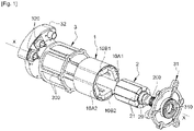
- the device which is the subject of the invention comprises a stator 1 in which a rotor 2 is rotatably mounted.
- the stator 1 is housed in a casing 3 forming a protection.
- This carcass is for example in the form of a cylindrical tube open at both ends, or closed at both ends. ends, or open at one end and closed at the other end.
- the length of the carcass 3 is between 5 cm and 30 cm, its internal diameter between 1.5 cm and 11.5 cm and its external diameter between 2 cm and 12 cm.
- the ends of the carcass 3 are respectively closed by a front flange 31 and a rear flange 32, the assembly forming, after assembly, a box in which the stator 1 is held. other of the stator 1, said flanges being parallel and extending perpendicularly to the axis of rotation XX of the rotor 2.
- the front flange 31 comprises a central opening 310, preferably provided with a bearing or a ball bearing, and through which passes one end of the shaft 20 of the rotor 2.
- this end is provided with toothings 200 adapted to be in direct or indirect engagement (for example by means of a reducer) with a mechanical member, preferably, but not exclusively, with a gearbox or clutch selector of a motor vehicle.
- the teeth 200 and/or the shaft 20 can of course be engaged with another mechanism.
- the rear flange 32 is provided with one or more connectors 320 to electrically supply the windings of the stator 1.
- the rear flange 32 can also support the electronic management unit (not shown) making it possible to control the electrical supply of the windings.
- the rear flange 32 is preferably provided with a bearing or a ball bearing supporting and guiding the other end of the shaft 20.
- the flanges 31 and 32 are fixed to the carcass 3 by screwing, riveting, welding, snap-fastening, etc. They make it possible in particular to protect the elements of the rotor 2 and of the stator 1, and to block said stator and said rotor axially so that after assembly, said rotor has only one degree of freedom in rotation around the axis XX .
- the carcass 3 and the flanges 31, 32 are preferably made of a non-ferromagnetic material, for example aluminum, plastic or carbon, to limit magnetic field leakage. To further limit field leakage, an annular space is provided between the outer wall of the stator 1 and the inner wall of the carcass 3, and into which resin is injected. In addition to or as a substitute for the resin, the stator 1 can be secured to the carcass 3 by screwing, riveting, welding, snap-fastening, etc.
- the carcass 3 advantageously comprises grooves or fins 300 to evacuate the heat generated by the activation of the windings of the stator 1.
- the stator 1 is in the form of a body having a generally cylindrical tubular shape and which is coaxial with the axis of rotation XX of the rotor 2.
- the length of the stator 1 is between 5 cm and 30 cm, its external diameter between 1 cm and 11 cm and its internal diameter between 0.5 cm and 10.5 cm. It is made of a ferromagnetic material, typically a material based on iron, cobalt, nickel, magnetic steel, etc. It can be monobloc and made in one piece or made in several pieces assembled together.
- the stator 1 is preferably a one-piece part.
- the internal wall of the stator 1 has first ferromagnetic cores 1A1, 1A2, 1B1, 1B2. These first cores can be attached to the internal wall of the stator 1. To simplify the design and reduce costs, it is however advantageous for the first cores 1A1, 1A2, 1B1, 1B2 to be obtained directly during molding and/or machining of the stator 1 and form therewith a single piece. They can be solid, or preferably hollow to lighten the structure of the stator 1. They are made of a ferromagnetic material which is preferably the same as that used for the body of the stator 1.
- first cores 1A1, 1A2, 1B1, 1B2 have the same shape and project radially towards the axis XX. They are in the form of longitudinal protrusions or ribs of rectangular or trapezoidal section, extending along the length of the stator 1. By way of example, their height is between 0.5 cm and 2 cm and their length between 5 cm and 30 cm.
- the first cores are arranged in pairs, respectively 1A1-1A2 and 1B1-1B2.
- the first cores of each pair face each other and are arranged symmetrically with respect to the axis of rotation X-X; they delimit the first air gaps.
- the stator 1 has two pairs of first cores, which pairs are symmetrical with respect to the sagittal median plane of said stator. More generally, the stator 1 has 2K pairs of first cores.
- K is an integer greater than or equal to 1. Indeed, the best results in terms of torque and power developed by the device that is the subject of the invention are obtained with K greater than or equal to 1, in particular K equal to or greater than 2 for large-scale industrial devices.
- Each first core has an axis which corresponds to its axis of symmetry and which intersects the axis of rotation XX.
- the first nuclei of the same pair have the same axis.
- the first nuclei of the pair 1A1-1A2 have a common NA-NA axis and those of the pair 1B1-1B2 a common NB-NB axis.
- these two axes are not orthogonal so that the cores 1A1, 1A2, 1B1, 1B2 are arranged in “X” rather than in “+”.
- the angle ⁇ between the axes NA-NA and NB-NB is for example between 3. ⁇ /8 and ⁇ /3.
- the angle ⁇ between the axes of these pairs of first cores is less than ⁇ /2K and greater than ⁇ /(4.K).
- the angle ⁇ is less than ⁇ and greater than (2. ⁇ ) /not.
- Windings 10A1, 10A2, 10B1, 10B2 are installed on the first cores 1A1, 1A2, 1B1, 1B2. More specifically, each first core 1A1, 1A2, 1B1, 1B2 supports and is magnetically coupled to a coil 10A1, 10A2, 10B1, 10B2 respectively.
- the windings 10A1, 10A2, 10B1, 10B2 and the first cores 1A1, 1A2, 1B1, 1B2 on which they are installed, have the same axis NA-NA, NB-NB which intersects the axis of rotation X-X of the rotor at the same place 2.
- windings consist 10A1, 10A2, 10B1, 10B2 of windings of electromagnetic turns.
- Each winding preferably consists of a copper wire wound over several turns and fixed to a core. They have one substantially rectangular shape.
- the windings 10A1, 10A2, 10B1, 10B2 are produced separately, outside of the stator 1. They are then placed around the first cores 1A1, 1A2, 1B1, 1B2.
- the windings 10A1, 10A2, 10B1, 10B2 are identical, that is to say they are made from wires of the same length and the same diameter, wound in the same way over the same number of turns. .
- the front face of the windings 10A1, 10A2, 10B1, 10B2 may or may not come flush with the end of the corresponding first cores 1A1, 1A2, 1B1, 1B2.
- the windings are arranged in pairs, respectively 10A1-10A2, and 10B1-10B2. More generally, there are K pairs of windings.
- the windings are connected to a management unit controlling their electrical supply (in particular the direction and the intensity of the current).
- the magnetic field generated by the coils 10A1, 10A2, 10B1, 10B2 depends on the direction and the intensity of the current flowing through them.
- the windings of the same pair are connected together so that they have the same polarity, NORTH or SOUTH, when they are powered.
- the management unit independently controls the power supply to each pair of windings so as to optimize (particularly in terms of positioning precision) the stopping of the rotor 2 in a position of stable equilibrium. It is possible in particular to provide multi-phase control of the management unit, where the number of phases is equal to the number of windings, these phases possibly or not being coupled in pairs if necessary.
- the management unit can also be configured so that, during the supply cycle, the direction of the current is reversed in order to generate a magnetic counter-field improving the precision and the stopping time in position of the rotor 2.
- each pole 21 preferably consists of a permanent magnet in the form of a longitudinal block, the cross section of which has the general shape of a crown sector. More particularly on the figure 7 , each magnet 21 comprises: - an external face 210 which is curved, concave, in the shape of a portion of a cylinder, - an internal face 211 which is flat in shape rectangular, - two flat inclined side faces 212, of rectangular shape, - two flat transverse faces 213, in the form of a crown sector.
- the internal face 211 is curved, convex, in the shape of a portion of a cylinder which is homothetic to the external face 210.
- the external face 210 is planar, of rectangular shape.
- their outer face 210 and preferably their inner face 211 have the same length as the coils 10A1, 10A2, 10B1, 10B2.
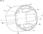
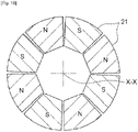
- the magnets 21 have the same shape and are arranged side by side around the axis XX so as to form a tubular hollow body whose outer wall is cylindrical or substantially cylindrical as illustrated in the figure 8 and 10 , which wall is magnetized over its entire surface (disregarding any angular offsets between the magnets 21).
- the magnets 21 are advantageously made of a magnetic material of the neodymium-iron-boron or samarium-cobalt type. Such magnets can be obtained by any method well known to those skilled in the art.
- the rotor 2 comprises 8 adjacent magnets 21, the external face 210 of each magnet describing an angular sector of approximately ⁇ /4.
- the magnets 21 are arranged in pairs, the magnets of each pair face each other and are arranged symmetrically with respect to the axis of rotation XX. More generally, if the stator 1 comprises 2K pairs of first cores and windings, the rotor 2 preferably comprises 4K pairs of magnet 21, the external face 210 each magnet preferably describing an angular sector of ⁇ /(4.K) or d 'about ⁇ /(4.K).
- the magnets can be assembled with a small angular offset between them (for example from 1° to 2°), this offset making it possible to simplify their positioning as well as their maintenance in position on the shaft. 20 as explained further in the description.
- the number of magnetized rotor poles 21 determines the number n of stable equilibrium positions (n being an even integer equal to or greater than 4, equal to or different at 8K). If the rotor 2 has n positions of stable equilibrium, each magnet 21 describes an angular sector of 2 ⁇ /n +/- 1° to 2°.
- the magnets 21 have radial magnetization, that is to say that the two faces 21a and 21b are magnetized so as to be able to generate a magnetic field which, in the air gaps, is perpendicular to the axis XX.
- the rotor poles 21 are diametrically magnetized so that their field lines are parallel to those of the coils 10A1, 10A2, 10B1, 10B2 located opposite said poles.
- the magnets 21 are adjacent and arranged around the axis XX with alternating polarities N and S, where the letters N and S correspond respectively to the North and South poles of the external faces 210. In other words, the magnets 21 have alternately opposite polarities.
- each magnet 21 is intended to be fixed on the external wall of the rotating shaft 20, which shaft is illustrated on the figure 11 .
- the fixing of the magnets 21 on the shaft 20 is preferably done by gluing.
- the shaft 20 has an outer wall of polygonal shape, the internal faces 211 of said magnets being flat and being fixed on the facets 201 of said shaft ( figure 11 ).
- a shaft 20 in the shape of a polygon and magnets 21 whose inner face 211 is flat are also preferably used.
- the latter is preferably made of a ferromagnetic material, for example steel.
- Shaft 20 is preferably hollow to lighten the structure of rotor 2.
- the rotor 2 has several positions of stable equilibrium (or magnetically stable positions) where it is not subjected to any torque. In these positions of equilibrium, the rotor 2 is only subjected to magnetic forces which cancel each other out. No mechanical stop element is used to block the rotor 2 in these positions.
- said magnets are offset from said cores in positions of stable equilibrium.
- the figure 2 illustrates such a position where the rotor 2 is in a first position of stable equilibrium.
- winding 10B1 is energized to have SOUTH polarity.
- the polarity of magnet 21a which faces coil 10B1 is NORTH.
- the SOUTH magnet which is closest to the core supporting the coil 10B1 is the magnet 21b which is located between the two coils 10A1 and 10B1.
- axis AA of magnet 21a is offset by an angle “ ⁇ ” from axis NN of the core supporting coil 10B1.
- the axis AA of the magnet 21a corresponds to its axis of symmetry and intersects the axis of rotation XX. The same phenomenon is found at the level of the coil 10B2 and the magnet 21c.
- a first magnetized pole 21a with axis AA is located opposite a first core 1B1 (or coil 10B1) with axis NN.
- another pole 21st magnet with axis BB is located opposite another first core 1A1 (or coil 10A1) with axis MM.
- the two magnetized poles 21a and 21e have the same polarity.
- the cores 1B1 and 1A1 (or windings 10B1, 10A1) each belong to a separate pair of first cores, these pairs being adjacent in the embodiment of the figure 2 .
- rotor 1 and stator 2 are configured so that angle ⁇ is strictly greater than angle ⁇ .
- the best results in terms of start-up responsiveness are obtained when ( ⁇ - ⁇ )/2 is greater than ⁇ /(2.n) and less than (3. ⁇ )/(2.n), where n is the number of positions of stable equilibrium.
- ( ⁇ - ⁇ )/2 is greater than ⁇ /(16.K) and less than (3. ⁇ )/(16. K).
- the winding 10B1 is supplied in the direction of generation of a NORTH polarity.
- a repulsive electromagnetic force is applied to the NORTH magnet 21a, which combines with an attractive electromagnetic force applied to the SOUTH magnet 21b.
- These two electromagnetic forces have tangential components in the same direction which combine to provide a high torque on starting and allow the rotor 2 to be very reactive.
- This torque is all the more important as the same electromagnetic forces are applied by symmetry to the NORTH magnet 21c and to the SOUTH magnet 21d located at the level of the winding 10B2 which is also powered. In any event, this torque is much greater than the residual torque (or holding torque) described further on in the description.
- the SOUTH magnet 21b has at least one portion located opposite the coil 10B1.
- the magnetic force of attraction which it undergoes is therefore optimal, thereby contributing to having a high torque at start-up.
- the same phenomenon applies to the SOUTH magnet 21d which has at least one portion located opposite the coil 10B2.
- a first magnet (ex: 21a, respectively 21c) is located opposite a first ferromagnetic core (ex: 1B1, respectively 1B2 ).
- At least a second magnet (ex: 21b, respectively 21d) which is adjacent to the first magnet (ex: 21a, respectively 21c), has a reverse polarity (SUD) of said first magnet and has at least one portion located opposite the first winding (ex: 10B1 respectively 10B2).
- the picture 3 illustrates the rotor 2 having engaged its rotation in the counterclockwise direction and located between two positions of stable equilibrium.
- a repulsive tangential force continues to be applied to the NORTH magnet 21a (and 21c), but with less intensity since said magnet moves away from the coil 10B1.
- the torque remains practically constant until the SOUTH magnet 21b (respectively 21d) is found opposite the NORTH winding 10B1 (respectively 10B2).
- This position illustrated on the figure 4 corresponds to a second position of stable equilibrium.
- This sequencing of the activations of the windings can be carried out as many times as necessary, so as to cause the rotor 2 to rotate continuously or step by step, over one or more revolutions.
- the other two windings 10A1 and 10A2 can be supplied with a NORTH polarity so that an attractive tangential force is applied to the SOUTH magnets 21f and 21h and a repulsive tangential force is applied to the NORTH magnets 21e and 21g.
- the windings 10B1 and 10B2 can no longer be supplied, the windings 10A1 and 10A2 alone ensuring the rise at the peak of the torque. Provision can also be made to use only the single pair of coils 10B1 and 10B2 and dispense with the use of the other two coils 10A1 and 10A2.
- Sensors are advantageously arranged inside stator 1 and/or on rotor 2 to determine the angular position of said rotor.
- the management unit activates or deactivates the power supply to the windings of the stator 1 according to the information provided by these position sensors.
- two diametrically opposed sensors are arranged on the internal wall of the stator 1, between the windings, and a sensor is positioned on the rotor 2.
- Sensors adapted to pick up the magnetic fluxes are preferably used.
- each first core 1A1, 1A2, 1B1, 1B2 is constantly located opposite a magnet 21 when the rotor 2 moves between two positions of stable equilibrium.
- Each first core 1A1, 1A2, 1B1 is therefore constantly crossed by lines of magnetic fields generated by a magnet 21, when the rotor 2 moves between two positions of stable equilibrium. Magnetic forces are thus permanently applied to the rotor 2 so that the torque developed is high.
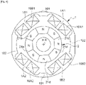
- the stator 1 comprises additional ferromagnetic cores 101, 102 devoid of winding. These second cores 101, 102 are located between the first cores 1A1, 1A2, 1B1, 1B2 so that there is an alternation of first cores with winding and second cores without winding. These second cores can be attached to the internal wall of the stator 1 or obtained directly during the molding and/or the machining of the said stator 1 and together form a single piece. They can be solid or hollow. They are made of a ferromagnetic material which is preferably the same as that used for the body of the stator 1.
- These second cores 101, 102 project radially towards the X-X axis. They are in the form of longitudinal protuberances or ribs, extending along the length of the stator 1, like the first cores 1A1, 1A2, 1B1, 1B2.
- the second cores 101, 102 are arranged in pairs.
- the second cores of each pair face each other and are arranged symmetrically with respect to the axis of rotation XX; they delimit second air gaps.
- the second nuclei of the same pair have the same axis.
- the stator 1 has two pairs of second cores, which pairs are symmetrical with respect to the sagittal median plane and to the transverse plane of said stator. More generally, if stator 1 has 2K pairs of first cores with winding, it also features 2K pairs of second cores without winding. On the figure 5 and 6 , the axes of each pair of second cores without winding are orthogonal (the angle between their axes is equal to ⁇ /2). If the stator 1 has 2K pairs of first cores with winding and 2K pairs of second cores without winding, the angle between the axes of said second cores without winding is equal to ⁇ /2K.
- the second cores 101, 102 do not all have the same dimensions, in particular in width. On the figure 5 and 6 , the second cores 101 of the first pair are less wide than those of the second pair 102.
- a second additional core 102 which is arranged between two first cores with winding and where the angle ( ⁇ - ⁇ ) between the respective axes NA-NA, NB-NB of said first cores with winding is the greatest ( ex: between the first cores 1A2 and 1B1 and/or between the first cores 1A1 and 1B2), then this second core 102 will have a greater width.
- the width of the second cores 101, 102 corresponds substantially to the distance separating two windings.
- each magnet 21 has at least a portion constantly located opposite a ferromagnetic core (with or without winding) when the rotor 2 moves between two positions of stable equilibrium and when said rotor is in a stable position of equilibrium.
- first stable position the NORTH magnets are located opposite the first cores with windings 1A1, 1A2, 1B1, 1B2; and the SOUTH magnets are located opposite the second cores without bobinagel 101 and 102.
- On the picture 3 (intermediate position) at least a portion of the SOUTH magnets and at least a portion of the NORTH magnets are located opposite the second cores 101 and 102.
- the SOUTH magnets are located opposite the first cores with windings 1A1, 1A2, 1B1, 1B2; and the NORTH magnets are located opposite the second cores 101 and 102.
- the magnetic field lines generated by the magnets 21 therefore permanently loop in one of the cores of the stator 1. This is particularly advantageous for increasing the residual torque in the positions of stable equilibrium, when the windings are not supplied. While being extremely reactive at the time of starting, the rotor 2 remains locked or fixed in a position of stable equilibrium, which is particularly advantageous when the device is used to actuate a device such as a gearbox selector or motor vehicle clutch. If this residual torque is not desirable, the second cores 101 and 102 will be eliminated. Moreover, by acting on the dimensions and/or the geometry of the second cores 101 and 102, it is possible to modify and/or adapt the intensity of this residual torque in order to adjust the compromise between the reactivity of the rotor at start-up and its locking in stable equilibrium position.
- the intensity of the residual torque is reduced.
- the adjustment of the dimensions and/or the geometry of the second cores 101 and 102 makes it possible to adapt the intensity of the residual torque and the starting torque in a position of stable equilibrium and/or the shape of the torque curve between two stable equilibrium positions.
- the first cores 1A1, 1A2, 1B1, 1B2 and the second cores 101, 102 are not arranged along the same circumference with respect to the axis of rotation XX of the rotor. They are not the same height.
- the first cores are arranged around a first circumference C1 and the second cores around a second circumference C2.
- the first circumference C1 coincides with the free end of the first cores and the second circumference C2 with the free end of the second cores.
- the diameter of the second circumference C2 is greater than the diameter of the first circumference C1. In other words, the second air gaps are increased relative to the first air gaps which are found closer to the rotor poles.
- the second circumference C2 By acting on the second circumference C2, it is thus possible to modify and/or adapt the intensity of the residual torque (and the starting torque) in the positions of stable equilibrium and/or the shape of the torque curve between two positions d steady equilibrium. It is also conceivable to adjust the height of certain second cores (ie the second cores do not all have the same height and/or are not arranged along the same circumference) so as to adapt the intensity of the residual torque.
- the rotor poles 21 can take the form of electromagnets.
- one or more features and/or steps exposed only in one embodiment can be generalized to the other embodiments.
- one or more features and/or steps set forth only in one embodiment may be combined with one or more other features and/or steps set forth only in another embodiment.
Landscapes
- Engineering & Computer Science (AREA)
- Power Engineering (AREA)
- Permanent Magnet Type Synchronous Machine (AREA)
Description
L'invention concerne un dispositif d'entraînement rotatif électromagnétique, ainsi que l'utilisation d'un tel dispositif pour actionner un sélecteur de boîte de vitesses ou d'embrayage d'un véhicule automobile. Le dispositif objet de l'invention n'est toutefois pas limité à cette utilisation. L'invention a encore pour objet un procédé de fabrication d'un dispositif d'entraînement rotatif électromagnétique.The invention relates to an electromagnetic rotary drive device, as well as the use of such a device for actuating a gearbox or clutch selector of a motor vehicle. The device that is the subject of the invention is however not limited to this use. The invention also relates to a method of manufacturing an electromagnetic rotary drive device.
Le domaine de l'invention concerne les actionneur s rotatifs électromagnétiques et plus particulièrement celui de tels actionneurs comportant un stator et un rotor.The field of the invention relates to electromagnetic rotary actuators and more particularly that of such actuators comprising a stator and a rotor.
Les dispositifs d'entraînement rotatif électromagnétiques sont connus de l'art antérieur et par exemple décrit dans les documents brevets
L'introduction d'un courant dans les bobinages traversés par les champs magnétiques induits par les pôles aimantés génèrent des forces électromagnétiques susceptibles d'entraîner la rotation du rotor. Aussi, en commandant l'alimentation électrique des bobinages (intensité et sens du courant circulant dans les bobinages) en fonction de la position angulaire du rotor, on crée un champ magnétique tournant adapté pour entraîner en rotation ledit rotor. L'alimentation électrique des bobinages est habituellement commandée par une unité de gestion.The introduction of a current in the coils through which the magnetic fields induced by the magnetized poles generate electromagnetic forces capable of causing the rotation of the rotor. Also, by controlling the power supply to the windings (intensity and direction of the current flowing in the windings) as a function of the angular position of the rotor, a rotating magnetic field is created suitable for rotating said rotor. The power supply to the windings is usually controlled by a management unit.
Le rotor peut présenter une ou plusieurs positions d'équilibre stable où ledit rotor n'est soumis à aucun couple, c'est-à-dire qu'il ne tourne pas. Physiquement, une position d'équilibre stable existe lorsqu'on a un équilibre magnétique entre le rotor et le stator. Lorsque les bobinages ne sont pas alimentés, le rotor reste également en position stable du fait de l'attraction magnétique qui subsiste entre les pôles aimantés et les noyaux ferromagnétiques. Selon l'intensité de ce couple résiduel (ou couple de maintien), le rotor 2 est plus ou moins verrouillé en position, ce qui peut être avantageux ou désavantageux selon le type d'application souhaitée.The rotor can have one or more positions of stable equilibrium where said rotor is not subjected to any torque, that is to say it does not rotate. Physically, a stable equilibrium position exists when there is magnetic equilibrium between the rotor and the stator. When the windings are not energized, the rotor remains also in a stable position due to the magnetic attraction that remains between the magnetized poles and the ferromagnetic cores. Depending on the intensity of this residual torque (or holding torque), the
Lorsqu'on inverse le sens du courant dans les bobinages (c'est-à-dire qu'on inverse leur polarité), les pôles aimantés vont se déplacer par attraction magnétique jusqu'à atteindre une autre position stable. En commandant de façon judicieuse et alternée l'alimentation des bobinages, le rotor va tourner dans le sens horaire ou antihoraire, avec un couple plus ou moins important. La gestion de cette alimentation électrique est bien connue de l'homme du métier.When the direction of the current in the windings is reversed (ie their polarity is reversed), the magnetized poles will move by magnetic attraction until they reach another stable position. By judiciously and alternately controlling the power supply to the windings, the rotor will turn clockwise or counterclockwise, with a more or less significant torque. The management of this electrical power supply is well known to those skilled in the art.
Lorsque le rotor quitte sa position d'équilibre stable, la force tangentielle d'attraction magnétique appliquée sur les pôles rotoriques est relativement faible au démarrage, de sorte que le couple au démarrage est également faible. Cela est problématique lorsque le rotor doit actionner un mécanisme tel qu'un sélecteur de boîte de vitesses ou d'embrayage d'un véhicule automobile. Sauf à sur-dimensionner les bobinages et les pôles magnétiques, de tels mécanismes ne pourront pas être actionnés. En outre, le temps mis par le rotor pour atteindre la nouvelle position d'équilibre stable n'est pas optimal, le rotor manquant de réactivité au démarrage. Le couple au démarrage et/ou la réactivité au démarrage sont également influencés par le couple résiduel.When the rotor leaves its position of stable equilibrium, the tangential force of magnetic attraction applied to the rotor poles is relatively weak at starting, so that the starting torque is also weak. This is problematic when the rotor must actuate a mechanism such as a gearbox or clutch selector of a motor vehicle. Unless the windings and the magnetic poles are oversized, such mechanisms cannot be actuated. In addition, the time taken by the rotor to reach the new position of stable equilibrium is not optimal, the rotor lacking in reactivity on starting. The starting torque and/or the starting reactivity are also influenced by the residual torque.
Face à cet état des choses, un objectif de l'invention est de proposer un dispositif d'entraînement rotatif électromagnétique permettant d'augmenter le couple au démarrage. Un autre objectif de l'invention est de proposer un dispositif d'entraînement rotatif électromagnétique permettant au rotor d'être extrêmement réactif et d'atteindre plus rapidement une nouvelle position d'équilibre stable, tout en s'assurant que le rotor soit bien maintenu en position d'équilibre stable. Encore un autre objectif de l'invention est de proposer un dispositif d'entraînement rotatif électromagnétique de conception simple, compact, robuste et peu onéreux.Faced with this state of affairs, an object of the invention is to propose an electromagnetic rotary drive device making it possible to increase the starting torque. Another object of the invention is to provide an electromagnetic rotary drive device allowing the rotor to be extremely responsive and to reach a new position of stable equilibrium more quickly, while ensuring that the rotor is well maintained. in a position of stable equilibrium. Yet another object of the invention is to provide an electromagnetic rotary drive device of simple, compact, robust and inexpensive design.
La solution proposée par l'invention est un dispositif d'entraînement rotatif électromagnétique, comportant un stator et un rotor et dans lequel :
- le stator comporte des premiers noyaux ferromagnétiques sur lesquels sont installées des bobinages adaptés pour créer un champ magnétique, lesquels premiers noyaux sont de même forme et une extrémité libre desdits premiers noyaux est agencée selon une première circonférence par rapport à l'axe de rotation du rotor,
- le rotor comporte des pôles rotoriques aimantés,
- une unité de gestion commande l'alimentation électrique des bobinages du stator en fonction de la position angulaire du rotor, de façon à créer un champ magnétique tournant adapté pour entraîner en rotation ledit rotor,
- le rotor présente plusieurs positions d'équilibre stable.
- the stator comprises first ferromagnetic cores on which are installed windings adapted to create a magnetic field, which first cores are of the same shape and a free end of said first cores is arranged along a first circumference with respect to the axis of rotation of the rotor ,
- the rotor comprises magnetized rotor poles,
- a management unit controls the power supply to the windings of the stator as a function of the angular position of the rotor, so as to create a rotating magnetic field adapted to drive said rotor in rotation,
- the rotor has several positions of stable equilibrium.
Ce dispositif est remarquable en ce que :
- les premiers noyaux ferromagnétiques et les pôles aimantés sont configurés et agencés de sorte que :
- o dans les positions d'équilibre stable, les pôles aimantés sont désaxés des premiers noyaux ferromagnétiques,
- o chaque premier noyau ferromagnétique est constamment situé en vis-à-vis d'un des pôles aimantés lorsque le rotor se déplace entre deux positions d'équilibre stable,
- le stator comporte des seconds noyaux ferromagnétiques dépourvus de bobinage, lesquels seconds noyaux sont situés entre les premiers noyaux ferromagnétiques de manière à ce que ledit stator présente une alternance de noyaux avec bobinage et de noyaux sans bobinage,
- les seconds noyaux ferromagnétiques sont configurés pour exercer un couple résiduel sur le rotor, lesquels seconds noyaux n'ont pas tous les mêmes dimensions et/ou la même géométrie et une extrémité libre desdits seconds noyaux est agencée selon une seconde circonférence par rapport à l'axe de rotation du rotor, le diamètre de ladite seconde circonférence étant différente du diamètre de la première circonférence.
- the first ferromagnetic cores and the magnetized poles are configured and arranged so that:
- o in positions of stable equilibrium, the magnetized poles are offset from the first ferromagnetic cores,
- o each first ferromagnetic core is constantly located opposite one of the magnetized poles when the rotor moves between two positions of stable equilibrium,
- the stator comprises second ferromagnetic cores without winding, which second cores are located between the first ferromagnetic cores so that said stator has an alternation of cores with winding and cores without winding,
- the second ferromagnetic cores are configured to exert a residual torque on the rotor, which second cores do not all have the same dimensions and/or the same geometry and a free end of said second cores is arranged according to a second circumference with respect to the axis of rotation of the rotor, the diameter of said second circumference being different from the diameter of the first circumference.
Le désaxage est une solution simple qui permet d'induire, dès le démarrage, une force tangentielle de répulsion magnétique entre les pôles rotoriques aimantés et les bobinages qui sont de même polarité et en vis-à-vis au démarrage (c'est-à-dire lorsque le rotor quitte une position d'équilibre stable). Au démarrage, cette force électromagnétique tangentielle répulsive permet non seulement de donner un couple important au démarrage, quel que soit le sens de rotation demandé, mais également de permettre au rotor d'être très réactif. En outre, chaque noyau ferromagnétique étant constamment situé en vis-à-vis d'un des pôles aimantés, chaque noyau génère constamment, après démarrage, une force tangentielle de répulsion magnétique et/ou une force tangentielle d'attraction magnétique sur tout ou partie des pôles aimantés lorsque le rotor se déplace entre deux positions d'équilibre stable. Le rotor est ainsi soumis à un couple important, et pratiquement constant, lorsqu'il se déplace entre deux positions d'équilibre stable, ledit rotor atteignant très rapidement la nouvelle position d'équilibre stable. La configuration et l'agencement des seconds noyaux ferromagnétiques permet en outre de générer un couple résiduel permettant d'assurer un verrouillage satisfaisant du rotor dans les positions d'équilibre stable. On a ainsi un bon compromis entre la réactivité du rotor au démarrage et son maintien en position d'équilibre stable.Misalignment is a simple solution which makes it possible to induce, from start-up, a tangential force of magnetic repulsion between the magnetized rotor poles and the windings which are of the same polarity and face each other at start-up (i.e. say when the rotor leaves a stable equilibrium position). At start-up, this repulsive tangential electromagnetic force not only gives a high torque at start-up, regardless of the direction of rotation requested, but also allows the rotor to be very reactive. In addition, each ferromagnetic core being constantly located opposite one of the magnetized poles, each core constantly generates, after starting, a tangential force of magnetic repulsion and/or a tangential force of magnetic attraction on all or part magnetized poles when the rotor moves between two positions of stable equilibrium. The rotor is thus subjected to a high torque, and practically constant, when it moves between two positions of stable equilibrium, said rotor very quickly reaching the new position of stable equilibrium. The configuration and arrangement of the second ferromagnetic cores also makes it possible to generate a residual torque making it possible to ensure satisfactory locking of the rotor in the positions of stable equilibrium. There is thus a good compromise between the reactivity of the rotor at start-up and its maintenance in a position of stable equilibrium.
D'autres caractéristiques avantageuses de l'invention sont listées ci-dessous. Chacune de ces caractéristiques peut être considérée seule ou en combinaison avec les caractéristiques remarquables définies ci-dessus, et faire l'objet, le cas échéant, d'une ou plusieurs demandes de brevet divisionnaires :
- Selon un mode de réalisation, le diamètre de la seconde circonférence est plus grand que le diamètre de la première circonférence.
- Selon un mode de réalisation, dans une position d'équilibre stable : - un premier pôle aimanté est situé en face d'un premier noyau ferromagnétique, lequel premier pôle aimanté présente un axe et lequel premier noyau ferromagnétique présente un axe ; - un second pôle aimanté est situé en face d'un autre premier noyau ferromagnétique, lequel second pôle aimanté présente une polarité qui est inverse de la polarité du bobinage installé sur ledit autre premier noyau, lesdits premiers noyaux appartenant chacun à une paire distincte de premiers noyaux, lequel second pôle aimanté présente un axe et lequel autre premier noyau ferromagnétique présente un axe ; - les axes desdits premiers noyaux formant un angle β et les axes desdits pôles aimantés formant un angle θ ; le rotor et le stator sont configurés de sorte que : θ > β et π/(2.n) < (θ-β)/2 < (3. π)/(2.n), où n est le nombre de positions d'équilibre stable du rotor.
- Selon un mode de réalisation : - les seconds noyaux ferromagnétiques sont agencés par paire, les noyaux de chaque paire se faisant face et étant disposés symétriquement par rapport à l'axe de rotation du rotor ; - un second noyau ferromagnétique qui est disposé entre deux premiers noyaux et où un angle β entre les axes respectifs desdits premiers noyaux est le plus faible, alors ledit second noyau a une première largeur ; - à l'inverse, un second noyau ferromagnétique qui est disposé entre deux premiers noyaux et où un angle (π-β) entre les axes respectifs desdits premiers noyaux est le plus important, alors ce second noyau a une seconde largeur qui est plus importante que la première largeur.
- Selon un mode de réalisation : - le stator comprend des paires de premiers noyaux ferromagnétiques, et 2K paires de seconds noyaux ferromagnétiques, K étant un nombre entier égal ou supérieur à 1 ; - les bobinages de chaque paire de premiers noyaux ferromagnétiques sont disposés symétriquement par rapport à l'axe de rotation du rotor ; - le rotor présente n pôles rotoriques adjacents, lesquels pôles ont des polarités alternativement opposées, n étant un nombre entier pair supérieur ou égal à 4, le nombre n de pôles rotoriques correspondant au nombre de positions d'équilibre stable dudit rotor.
- Selon un mode de réalisation : - les premiers noyaux ferromagnétiques d'une même paire ont le même axe ; - l'angle β entre les axes de ces paires de premiers noyaux ferromagnétiques est inférieur à π et supérieur à (2. π)/n.
- Selon un mode de réalisation, les pôles aimantés sont diamétralement magnétisés de sorte que leurs lignes de champs soient parallèles à celles des bobinages situés en vis-à-vis desdits pôles.
- Selon un mode de réalisation, une face externe de chaque aimant située en vis-à-vis du stator décrit un secteur angulaire de (2.π) /n +/- 1° à 2°.
- Selon un mode de réalisation, dans une position d'équilibre stable du rotor ou entre deux positions d'équilibre stable dudit rotor, les pôles aimantés présentent au moins une portion constamment située en vis-à-vis d'un premier noyau ferromagnétique avec bobinage ou d'un second noyau ferromagnétique sans bobinage.
- According to one embodiment, the diameter of the second circumference is greater than the diameter of the first circumference.
- According to one embodiment, in a position of stable equilibrium: - a first magnetized pole is located opposite a first ferromagnetic core, which first magnetized pole has an axis and which first ferromagnetic core has an axis; - a second magnetized pole is located opposite another first ferromagnetic core, which second magnetized pole has a polarity which is inverse to the polarity of the winding installed on said other first core, said first cores each belonging to a distinct pair of first cores, which second magnetized pole has an axis and which other first ferromagnetic core has an axis; - the axes of said first cores forming an angle β and the axes of said magnetized poles forming an angle θ; the rotor and the stator are configured so that: θ > β and π/(2.n) < (θ-β)/2 < (3. π)/(2.n), where n is the number of positions stable equilibrium of the rotor.
- According to one embodiment: - the second ferromagnetic cores are arranged in pairs, the cores of each pair facing each other and being arranged symmetrically with respect to the axis of rotation of the rotor; - a second ferromagnetic core which is arranged between two first cores and where an angle β between the respective axes of said first cores is the smallest, then said second core has a first width; - conversely, a second ferromagnetic core which is arranged between two first cores and where an angle (π-β) between the respective axes of said first cores is greater, then this second core has a second width which is greater than the first width.
- According to one embodiment: - the stator comprises pairs of first ferromagnetic cores, and 2K pairs of second ferromagnetic cores, K being an integer equal to or greater than 1; - the windings of each pair of first ferromagnetic cores are arranged symmetrically with respect to the axis of rotation of the rotor; - the rotor has n adjacent rotor poles, which poles have alternately opposite polarities, n being an even integer greater than or equal to 4, the number n of rotor poles corresponding to the number of stable equilibrium positions of said rotor.
- According to one embodiment: - the first ferromagnetic cores of the same pair have the same axis; - the angle β between the axes of these pairs of first ferromagnetic cores is less than π and greater than (2.π)/n.
- According to one embodiment, the magnetized poles are diametrically magnetized so that their field lines are parallel to those of the windings located opposite said poles.
- According to one embodiment, an outer face of each magnet located opposite the stator describes an angular sector of (2.π)/n +/- 1° to 2°.
- According to one embodiment, in a position of stable equilibrium of the rotor or between two positions of stable equilibrium of said rotor, the magnetized poles have at least a portion constantly located opposite a first ferromagnetic core with winding or a second ferromagnetic core without winding.
Un autre aspect de l'invention concerne un procédé de fabrication d'un dispositif conforme à l'une des caractéristiques précédentes, comprenant une étape consistant à régler l'intensité du couple résiduel exercé sur le rotor dans une position d'équilibre stable, lequel réglage est réalisé en agissant sur les dimensions et/ou la géométrie des seconds noyaux et/ou en agissant sur la seconde circonférence.Another aspect of the invention relates to a method of manufacturing a device conforming to one of the preceding characteristics, comprising a step consisting in adjusting the intensity of the residual torque exerted on the rotor in a position of stable equilibrium, which adjustment is achieved by acting on the dimensions and/or the geometry of the second cores and/or by acting on the second circumference.
Encore un autre aspect de l'invention concerne un sélecteur de boîte de vitesses ou d'embrayage d'un véhicule automobile, caractérisé en ce que ledit sélecteur est relié au rotor du dispositif conforme à l'une des caractéristiques précédentes.Yet another aspect of the invention relates to a motor vehicle gearbox or clutch selector, characterized in that said selector is connected to the rotor of the device conforming to one of the preceding characteristics.
Encore un autre aspect de l'invention concerne un véhicule automobile comportant un sélecteur de boîte de vitesses ou d'embrayage, caractérisé en ce que ledit sélecteur étant relié au rotor du dispositif conforme à l'une des caractéristiques précédentes.Yet another aspect of the invention relates to a motor vehicle comprising a gearbox or clutch selector, characterized in that said selector is connected to the rotor of the device conforming to one of the preceding characteristics.
D'autres avantages et caractéristiques de l'invention apparaîtront mieux à la lecture de la description d'un mode de réalisation préféré qui va suivre, en référence aux dessins annexés, réalisés à titre d'exemples indicatifs et non limitatifs et sur lesquels :
- [
Fig. 1 ] est une vue d'ensemble d'un dispositif conforme à l'invention, - [
Fig. 2 ] est une vue schématique en coupe transversale d'un stator et d'un rotor conforme à l'invention, le rotor étant dans une première position d'équilibre stable, - [
Fig. 3 ] est une vue schématique en coupe transversale d'un stator et d'un rotor conforme à l'invention, le rotor étant situé entre deux positions d'équilibre stable, - [
Fig. 4 ] est une vue schématique en coupe transversale d'un stator et d'un rotor conforme à l'invention, le rotor étant dans une seconde position d'équilibre stable, - [
Fig. 5 ] est une vue schématique en perspective d'un châssis d'un stator selon l'invention, - [
Fig. 6 ] est une vue en coupe transversale du châssis de lafigure 5 , - [
Fig. 7 ] est une vue en perspective d'un aimant formant un pôle rotorique, - [
Fig. 8 ] est une vue en perspective d'un assemblage d'aimants selon lafigure 7 , - [
Fig. 9 ] est une vue schématique en coupe de l'aimant de lafigure 6 et sur laquelle sont représentées des lignes de champs magnétiques, - [
Fig. 10 ] est une vue en coupe transversale de l'assemblage de lafigure 8 , - [
Fig. 11 ] est une vue schématique en perspective d'un arbre adapté pour supporter l'assemblage de lafigure 8 .
- [
Fig. 1 ] is an overview of a device according to the invention, - [
Fig. 2 ] is a schematic cross-sectional view of a stator and a rotor according to the invention, the rotor being in a first position of stable equilibrium, - [
Fig. 3 ] is a schematic cross-sectional view of a stator and a rotor according to the invention, the rotor being located between two positions of stable equilibrium, - [
Fig. 4 ] is a schematic cross-sectional view of a stator and a rotor according to the invention, the rotor being in a second position of stable equilibrium, - [
Fig. 5 ] is a schematic perspective view of a frame of a stator according to the invention, - [
Fig. 6 ] is a cross-sectional view of the frame of thefigure 5 , - [
Fig. 7 ] is a perspective view of a magnet forming a rotor pole, - [
Fig. 8 ] is a perspective view of a magnet assembly according to thefigure 7 , - [
Fig. 9 ] is a schematic sectional view of the magnet of thefigure 6 and on which are represented lines of magnetic fields, - [
Fig. 10 ] is a cross-sectional view of the assembly of thefigure 8 , - [
Fig. 11 ] is a schematic perspective view of a shaft adapted to support the assembly of thefigure 8 .
Tel qu'utilisé ici, sauf indication contraire, l'utilisation des adjectifs ordinaux «premier», «second», etc., pour décrire un objet indique simplement que différentes occurrences d'objets similaires sont mentionnées et n'implique pas nécessairement que les objets ainsi décrits doivent être dans une séquence donnée, que ce soit dans le temps, dans l'espace, dans un classement ou de toute autre manière.As used herein, unless otherwise specified, the use of the ordinal adjectives "first", "second", etc., to describe an object merely indicates that different occurrences of similar objects are mentioned and does not necessarily imply that the objects thus described must be in a given sequence, whether in time, in space, in a classification or in any other way.
Le dispositif objet de l'invention peut être utilisé comme actionneur et être intégré dans un véhicule automobile terrestre (voiture, moto, ...), marin (bateau, sous-marin, torpille, ...), aérien (avion, drone, hélicoptère, ...), ou dans tout autre appareil, par exemple un appareil électroménager, un jouet, etc. Le dispositif objet de l'invention peut également être utilisé dans d'autres applications de positionnement indexé à angle fixe.The device that is the subject of the invention can be used as an actuator and be integrated into a motor vehicle on land (car, motorcycle, etc.), marine (boat, submarine, torpedo, etc.), aerial (aircraft, drone , helicopter, ...), or in any other device, for example a household appliance, a toy, etc. The device that is the subject of the invention can also be used in other fixed-angle indexed positioning applications.
Sur la
Les extrémités de la carcasse 3 sont respectivement fermées par une flasque avant 31 et une flasque arrière 32, l'ensemble formant, après assemblage, un boîtier dans lequel est maintenu le stator 1. Les flasques 31, 32 sont disposées de part et d'autre du stator 1, lesdites flasques étant parallèles et s'étendant perpendiculairement à l'axe de rotation X-X du rotor 2. Le flasque avant 31 comporte une ouverture centrale 310, préférentiellement pourvue d'un palier ou d'un roulement à billes, et au travers de laquelle passe une extrémité de l'arbre 20 du rotor 2. Sur la
Le flasque arrière 32 est pourvue d'un ou plusieurs connecteurs 320 pour alimenter électriquement les bobinages du stator 1. Le flasque arrière 32 peut également supporter l'unité de gestion électronique (non représentée) permettant de commander l'alimentation électrique des bobinages. Le flasque arrière 32 est préférentiellement munie d'un palier ou d'un roulement à billes supportant et guidant l'autre extrémité de l'arbre 20.The
Les flasques 31 et 32 sont fixées sur la carcasse 3 par vissage, rivetage, soudage, encliquetage, etc. Elles permettent notamment de protéger les éléments du rotor 2 et du stator 1, et de bloquer axialement ledit stator et ledit rotor de sorte qu'après assemblage, ledit rotor n'a qu'un degré de liberté en rotation autour de l'axe X-X. La carcasse 3 et les flasques 31, 32 sont préférentiellement réalisées dans un matériau non ferromagnétique, par exemple en aluminium, en plastique ou en carbone, pour limiter les fuites de champs magnétiques. Pour limiter encore davantage les fuites de champs, on ménage un espace annulaire entre la paroi externe du stator 1 et la paroi interne de la carcasse 3, et dans lequel on injecte de la résine. En complément ou en substitution de la résine, le stator 1 peut être solidarisé à la carcasse 3 par vissage, rivetage, soudage, encliquetage, etc.The
Sur la
Sur les
Sur les
Ces premiers noyaux 1A1, 1A2, 1B1, 1B2 ont la même forme et font saillie radialement vers l'axe X-X. Ils se présentent sous la forme de protubérances ou nervures longitudinales de section rectangulaire ou trapézoïdale, s'étendant dans la longueur du stator 1. À titre d'exemple, leur hauteur est comprise entre 0,5 cm et 2 cm et leur longueur entre 5 cm et 30 cm.These first cores 1A1, 1A2, 1B1, 1B2 have the same shape and project radially towards the axis XX. They are in the form of longitudinal protrusions or ribs of rectangular or trapezoidal section, extending along the length of the
Les premiers noyaux sont agencés par paire, respectivement 1A1-1A2 et 1B1-1B2. Les premiers noyaux de chaque paire se font face et sont disposés symétriquement par rapport à l'axe de rotation X-X ; ils délimitent des premiers entrefers. Sur les figures annexées, le stator 1 présente deux paires de premiers noyaux, lesquelles paires sont symétriques par rapport au plan médian sagittal dudit stator. De manière plus générale, le stator 1 présente 2K paires de premiers noyaux. Dans la suite de la description, K est un nombre entier supérieur ou égal à 1. En effet, les meilleurs résultats en termes de couple et de puissance développés par le dispositif objet de l'invention sont obtenus avec K supérieur ou égal à 1, notamment K égal ou supérieur à 2 pour des dispositifs industriels de grande échelle.The first cores are arranged in pairs, respectively 1A1-1A2 and 1B1-1B2. The first cores of each pair face each other and are arranged symmetrically with respect to the axis of rotation X-X; they delimit the first air gaps. In the appended figures, the
Chaque premier noyau présente un axe qui correspond à son axe de symétrie et qui coupe l'axe de rotation X-X. Les premiers noyaux d'une même paire ont le même axe. Sur la
Des bobinages 10A1, 10A2, 10B1, 10B2 sont installés sur les premiers noyaux 1A1, 1A2, 1B1, 1B2. Plus précisément, chaque premier noyau 1A1, 1A2, 1B1, 1B2 supporte et est couplé magnétiquement à un bobinage 10A1, 10A2, 10B1, 10B2 respectivement. Les bobinages 10A1, 10A2, 10B1, 10B2 et les premiers noyaux 1A1, 1A2, 1B1, 1B2 sur lesquels ils sont installés, ont le même axe NA-NA, NB-NB qui coupe au même endroit l'axe de rotation X-X du rotor 2.Windings 10A1, 10A2, 10B1, 10B2 are installed on the first cores 1A1, 1A2, 1B1, 1B2. More specifically, each first core 1A1, 1A2, 1B1, 1B2 supports and is magnetically coupled to a coil 10A1, 10A2, 10B1, 10B2 respectively. The windings 10A1, 10A2, 10B1, 10B2 and the first cores 1A1, 1A2, 1B1, 1B2 on which they are installed, have the same axis NA-NA, NB-NB which intersects the axis of rotation X-X of the rotor at the
Ces bobinages consistent 10A1, 10A2, 10B1, 10B2 en des enroulements de spires électromagnétiques. Chaque bobinage est préférentiellement constitué d'un fil de cuivre enroulé sur plusieurs tours et fixé sur un noyau. Ils ont une forme sensiblement rectangulaire. En pratique, les bobinages 10A1, 10A2, 10B1, 10B2 sont réalisés séparément, hors du stator 1. Ils sont ensuite placés autour des premiers noyaux 1A1, 1A2, 1B1, 1B2. De préférence, les bobinages 10A1, 10A2, 10B1, 10B2 sont identiques, c'est-à-dire qu'ils sont réalisés à partir de fils de même longueur et de même diamètre, enroulés de la même façon sur un même nombre de tours. La face frontale des bobinages 10A1, 10A2, 10B1, 10B2 peut venir ou non affleurer l'extrémité des premiers noyaux 1A1, 1A2, 1B1, 1B2 correspondants.These windings consist 10A1, 10A2, 10B1, 10B2 of windings of electromagnetic turns. Each winding preferably consists of a copper wire wound over several turns and fixed to a core. They have one substantially rectangular shape. In practice, the windings 10A1, 10A2, 10B1, 10B2 are produced separately, outside of the
Comme les premiers noyaux 1A1, 1A2, 1B1, 1B2, les bobinages sont arrangés par paire, respectivement 10A1-10A2, et 10B1-10B2. Plus généralement, il y a K paires de bobinages. Les bobinages sont connectés à une unité de gestion commandant leur alimentation électrique (notamment le sens et l'intensité du courant). De manière connue de l'homme du métier, le champ magnétique généré par les bobinages 10A1, 10A2, 10B1, 10B2 dépend du sens et de l'intensité du courant qui les parcourt. Avantageusement, les bobinages d'une même paire sont connectés entre eux de sorte qu'ils présentent la même polarité, NORD ou SUD, lorsqu'ils sont alimentés. Selon un mode avantageux de réalisation, l'unité de gestion commande de manière indépendante l'alimentation de chaque paire de bobinages de manière à optimiser (notamment en termes de précision de positionnement) l'arrêt du rotor 2 dans une position d'équilibre stable. On peut notamment prévoir pilotage multi-phasés de l'unité de gestion, où le nombre de phases est égal au nombre de bobinages, ces phases pouvant ou non être couplées deux à deux si besoin. L'unité de gestion peut également être configurée pour que, durant le cycle d'alimentation, le sens du courant soit inversé afin de générer un contre-champ magnétique améliorant la précision et le temps d'arrêt en position du rotor 2.Like the first cores 1A1, 1A2, 1B1, 1B2, the windings are arranged in pairs, respectively 10A1-10A2, and 10B1-10B2. More generally, there are K pairs of windings. The windings are connected to a management unit controlling their electrical supply (in particular the direction and the intensity of the current). As known to those skilled in the art, the magnetic field generated by the coils 10A1, 10A2, 10B1, 10B2 depends on the direction and the intensity of the current flowing through them. Advantageously, the windings of the same pair are connected together so that they have the same polarity, NORTH or SOUTH, when they are powered. According to an advantageous embodiment, the management unit independently controls the power supply to each pair of windings so as to optimize (particularly in terms of positioning precision) the stopping of the
Le rotor 2 comporte des pôles rotoriques aimantés 21. En se rapportant aux
Pour optimiser les forces magnétiques qui s'appliquent sur les aimants 21, leur face externe 210 et préférentiellement leur face interne 211, ont la même longueur que les bobinages 10A1, 10A2, 10B1, 10B2.To optimize the magnetic forces which are applied to the
Les aimants 21 ont la même forme et sont agencés côte à côte autour de l'axe X-X de manière à former un corps creux tubulaire dont la paroi externe est cylindrique ou sensiblement cylindrique comme illustrée sur les
Les aimants 21 sont avantageusement réalisés dans un matériau magnétique du type néodyme-fer-bore ou samarium-cobalt. De tels aimants peuvent être obtenus par tout procédé bien connu de l'homme du métier.The
Sur les figures annexées, le rotor 2 comporte 8 aimants 21 adjacents, la face externe 210 de chaque aimant décrivant un secteur angulaire d'environ π/4. La demanderesse a pu constater que cette configuration permettait d'obtenir des résultats optimums en matière de rendement et de compacité. Les aimants 21 sont agencés par paire, les aimants de chaque paire se font face et sont disposés symétriquement par rapport à l'axe de rotation X-X. Plus généralement, si le stator 1 comporte 2K paires de premiers noyaux et de bobinages, le rotor 2 comporte préférentiellement 4K paires d'aimant 21, la face externe 210 chaque aimant décrivant préférentiellement un secteur angulaire de π/(4.K) ou d'environ π/(4.K). Par « environ », on entend que les aimants peuvent être assemblés avec un faible décalage angulaire entre eux (par exemple de 1° à 2°), ce décalage permettant de simplifier leur mise en position ainsi que leur maintien en position sur l'arbre 20 comme expliqué plus avant dans la description. Plus généralement encore, le nombre de pôles rotoriques aimantés 21 détermine le nombre n de positions d'équilibre stable (n étant un entier pair égal ou supérieur à 4, égal ou différent à 8K). Si le rotor 2 présente n positions d'équilibre stable, chaque aimant 21 décrit un secteur angulaire de 2π/n +/- 1° à 2°.In the appended figures, the
Les aimants 21 sont à aimantation radiale, c'est-à-dire que les deux faces 21a et 21b sont magnétisées de manière à pouvoir générer un champ magnétique qui, dans les entrefers, est perpendiculaire à l'axe X-X. En d'autres termes, les pôles rotoriques 21 sont diamétralement magnétisés de sorte que leurs lignes de champs soient parallèles à celles des bobinages 10A1, 10A2, 10B1, 10B2 situés en vis-à-vis desdits pôles. Comme illustrés sur la
La face interne 210 de chaque aimant 21 est destinée à venir se fixer sur la paroi externe de l'arbre tournant 20, lequel arbre est illustré sur la
Pour ne pas perturber le champ magnétique généré par les aimants 21 et pour que leurs lignes de champ se bouclent au cœur de l'arbre 20, ce dernier est préférentiellement réalisé dans un matériau ferromagnétique, par exemple en acier. L'arbre 20 est préférentiellement creux pour alléger la structure du rotor 2.In order not to disturb the magnetic field generated by the
Le rotor 2 présente plusieurs positions d'équilibre stable (ou positions stables magnétiquement) où il n'est soumis à aucun couple. Dans ces positions d'équilibre, le rotor 2 est uniquement soumis à des forces magnétiques qui s'annulent mutuellement. Aucun élément de butée mécanique n'est utilisé pour bloquer le rotor 2 dans ces positions.The
Les positions d'équilibre stable sont définies par les premiers noyaux 1A1, 1A2, 1B1, 1B2 et les pôles rotoriques aimantés 21. Si le stator 1 comporte 2K paires de premiers noyaux, le rotor 2 présente 4K paires de pôles rotoriques 21 et 8K positions d'équilibre stable (qui correspond au pas) ou n pôles rotoriques 21. Le nombre de positions d'équilibre stable correspond alors au nombre de pôles rotoriques 21. Dans l'exemple illustré par les figures annexées, le stator comporte 2 paires de premiers noyaux (K=1), le rotor présente 4 paires d'aimants 21 et 8 positions d'équilibre stable (n=8). Le rotor 2 a par conséquent un pas de 1/8 de tour. Le positionnement des premiers noyaux 1A1, 1A2, 1B1, 1B2 dépend du positionnement des positions d'équilibre stable.The positions of stable equilibrium are defined by the first cores 1A1, 1A2, 1B1, 1B2 and the
De par la configuration et l'agencement des premiers noyaux 1A1, 1A2, 1B1, 1B2 et des aimants 21, lesdits aimants sont désaxés desdits noyaux dans les positions d'équilibre stable.Due to the configuration and arrangement of the first cores 1A1, 1A2, 1B1, 1B2 and of the
La
La possibilité d'avoir le même couple important au démarrage, quel que soit le sens de rotation demandé et quel que soit la position d'équilibre stable, est également illustrée par une autre relation angulaire sur la
Pour faire tourner le rotor 2 dans le sens antihoraire, on alimente le bobinage 10B1 dans le sens d'une génération d'une polarité NORD. Une force électromagnétique répulsive s'applique sur l'aimant NORD 21a, qui se combine avec une force électromagnétique attractive appliquée sur l'aimant SUD 21b. Ces deux forces électromagnétiques ont des composantes tangentielles de même sens qui se combinent pour fournir un couple important au démarrage et permettent au rotor 2 d'être très réactif. Ce couple est d'autant plus important que les mêmes forces électromagnétiques s'appliquent par symétrie sur l'aimant NORD 21c et sur l'aimant SUD 21d situés au niveau du bobinage 10B2 également alimenté. En tout état de cause, ce couple est très supérieur au couple résiduel (ou couple de maintien) décrit plus avant dans la description.To make the
Sur la
La
Dans la position de mi-course illustrée sur la
Partant de la position d'équilibre stable de la
Des capteurs sont avantageusement disposés à l'intérieur du stator 1 et/ou sur le rotor 2 pour déterminer la position angulaire dudit rotor. L'unité de gestion active ou désactive l'alimentation des bobinages du stator 1 en fonction des informations fournies par ces capteurs de position. Préférentiellement, deux capteurs diamétralement opposés sont disposés sur la paroi interne du stator 1, entre les bobinages, et un capteur est positionné sur le rotor 2. On utilise préférentiellement des capteurs adaptés pour capter les flux magnétiques.Sensors are advantageously arranged inside
De par la configuration et l'agencement des aimants 21, la totalité de la surface externe du rotor 2 est aimantée (abstraction faite des éventuels décalages angulaires entre les aimants 21). Aussi, chaque premier noyau 1A1, 1A2, 1B1, 1B2 est constamment situé en vis-à-vis d'un aimant 21 lorsque le rotor 2 se déplace entre deux positions d'équilibre stable. Chaque premier noyau 1A1, 1A2, 1B1 est donc constamment traversé par des lignes de champs magnétiques générées par un aimant 21, lorsque le rotor 2 se déplace entre deux positions d'équilibre stable. Des forces magnétiques s'appliquent ainsi en permanence sur le rotor 2 de sorte que le couple développé est important.Due to the configuration and arrangement of the
Sur les
Ces seconds noyaux 101, 102 font saillie radialement vers l'axe X-X. Ils se présentent sous la forme de protubérances ou nervures longitudinales, s'étendant dans la longueur du stator 1, comme les premiers noyaux 1A1, 1A2, 1B1, 1B2.These
Les seconds noyaux 101, 102 sont agencés par paire. Les seconds noyaux de chaque paire se font face et sont disposés symétriquement par rapport à l'axe de rotation X-X ; ils délimitent des seconds entrefers. Les seconds noyaux d'une même paire ont le même axe. Sur les figures annexées, le stator 1 présente deux paires de seconds noyaux, lesquelles paires sont symétriques par rapport au plan médian sagittal et au plan transversal dudit stator. De manière plus générale, si le stator 1 présente 2K paires de premiers noyaux avec bobinage, il présente également 2K paires de seconds noyaux sans bobinage. Sur les
Les seconds noyaux 101, 102 n'ont pas tous les mêmes dimensions, notamment en largeur. Sur les
De cette manière, chaque aimant 21 présente au moins une portion constamment située en vis-à-vis d'un noyau ferromagnétique (avec ou sans bobinage) lorsque le rotor 2 se déplace entre deux positions d'équilibre stable et lorsque ledit rotor est dans une position d'équilibre stable. Sur la
Les lignes de champs magnétiques générées par les aimants 21 se bouclent donc en permanence dans un des noyaux du stator 1. Cela est particulièrement avantageux pour augmenter le couple résiduel dans les positions d'équilibre stable, lorsque les bobinages ne sont pas alimentés. Tout en étant extrêmement réactif au moment du démarrage, le rotor 2 reste verrouillé ou figé dans une position d'équilibre stable, ce qui est particulièrement avantageux lorsque le dispositif est utilisé pour actionner un dispositif tel qu'un sélecteur de boîte de vitesses ou d'embrayage de véhicule automobile. Si ce couple résiduel n'est pas souhaitable, les seconds noyaux 101 et 102 seront supprimés. Par ailleurs en agissant sur les dimensions et/ou la géométrie des seconds noyaux 101 et 102, on peut modifier et/ou adapter l'intensité de ce couple résiduel afin d'ajuste le compromis entre la réactivité du rotor au démarrage et son verrouillage en position d'équilibre stable. Notamment, en diminuant les dimensions des seconds noyaux 101 et 102 et/ou en augmentant le diamètre de la seconde circonférence (i.e. la profondeur des seconds entrefers), on diminue l'intensité du couple résiduel. Et inversement. En d'autres termes, l'ajustement des dimensions et/ou de la géométrie des seconds noyaux 101 et 102, permet d'adapter l'intensité du couple résiduel et le couple de démarrage dans une position d'équilibre stable et/ou la forme de la courbe du couple entre deux positions d'équilibre stable.The magnetic field lines generated by the
En outre, selon un mode de réalisation illustré notamment sur la
L'agencement des différents éléments et/ou moyens et/ou étapes de l'invention, dans les modes de réalisation décrits ci-dessus, ne doit pas être compris comme exigeant un tel agencement dans toutes les implémentations. En tout état de cause, on comprendra que diverses modifications peuvent être apportées à ces éléments et/ou moyens et/ou étapes, sans s'écarter de la portée de l'invention comme définie dans les revendications. En particulier les pôles rotoriques 21 peuvent se présenter sous la forme d'électro-aimants.The arrangement of the various elements and/or means and/or steps of the invention, in the embodiments described above, should not be understood as requiring such an arrangement in all implementations. In any case, it will be understood that various modifications can be made to these elements and/or means and/or steps, without departing from the scope of the invention as defined in the claims. In particular, the
Enfin, une ou plusieurs caractéristiques et/ou étapes exposées seulement dans un mode de réalisation peuvent être généralisées aux autres modes de réalisation. De même, une ou plusieurs caractéristiques et/ou étapes exposées seulement dans un mode de réalisation peuvent être combinées avec une ou plusieurs autres caractéristiques et/ou étapes exposées seulement dans un autre mode de réalisation.Finally, one or more features and/or steps exposed only in one embodiment can be generalized to the other embodiments. Likewise, one or more features and/or steps set forth only in one embodiment may be combined with one or more other features and/or steps set forth only in another embodiment.
Claims (13)
- An electromagnetic rotary drive, comprising a stator (1) and a rotor (2) and wherein:- The stator (1) comprises first ferromagnetic cores (1A1, 1A2, 1B1 and 1B2) on which windings (10A1, 10A2, 10B1 and 10B2) are installed and adapted to create a magnetic field, with the first cores having the same shape and positioned along a first circumference (C1) in relation to the axis of rotation (X-X) of the rotor (2)- The rotor (2) has magnetised rotor poles (21)- A control unit controls the power supply to the windings (10A1, 10A2, 10B1 and 10B2) of the stator (1) according to the angular position of the rotor (2), to create a rotating magnetic field adapted to rotate said rotor- The rotor (2) has several stable equilibrium positions- The first ferromagnetic cores (1A1, 1A2, 1B1 and 1B2) and the magnetised poles (21) are configured and positioned so that:∘ In the stable equilibrium positions, the magnetised poles (21) are offset from the first ferromagnetic cores (1A1, 1A2, 1B1 and 1B2)∘ Each first ferromagnetic core (1A1, 1A2, 1B1 and 1B2) is always located opposite one of the magnetised poles (21) when the rotor (2) moves between two stable equilibrium positions- The stator (1) has second ferromagnetic cores (101 and 102) without windings, with the second cores located between the first ferromagnetic cores (1A1, 1A2, 1B1 and 1B2) so that said stator has alternating cores with windings and cores without windingscharacterised in that the second ferromagnetic cores (101 and 102) are configured to exert a residual torque on the rotor (2), with the second cores not all having the same dimensions and/or geometry and positioned along a second circumference (C2) in relation to the axis of rotation (X-X) of the rotor (2), with the diameter of said second circumference being different from the diameter of the first circumference (C1).
- A device according to claim 1, wherein the diameter of the second circumference (C2) is larger than the diameter of the first circumference (C1).
- A device according to any of the preceding claims, wherein, in a stable equilibrium position:- A first magnetised pole (21a) is located opposite a first ferromagnetic core (1B1), with the first magnetised pole having an axis (A-A) and the first ferromagnetic core having an axis (N-N)- A second magnetised pole (21e) is positioned opposite another first ferromagnetic core (1A1), with said second magnetised pole having the same polarity as the first magnetised pole (21a), and said first cores (1B1 and 1A1) each belonging to a separate pair of first cores, with the second magnetised pole having an axis (B-B) and the other first ferromagnetic core having an axis (M-M)- The axes (N-N and M-M) of said first cores (1A1 and 1B1) forming an angle β and the axes (A-A and B-B) of said magnetised poles (21a and 21e) forming an angle θ- The rotor (1) and stator (2) are configured so that:∘ θ 〉 β and∘ π/(2.n) 〈 (θ-β)/2 〈 (3.π)/(2.n), where n is the number of stable equilibrium positions of rotor (2).
- A device according to any of the preceding claims, wherein:- The second ferromagnetic cores (101 and 102) are positioned in pairs, with each pair's cores facing each other and arranged symmetrically in relation to the axis of rotation (X-X) of the rotor (2)- A second ferromagnetic core (101) which is positioned between two first cores (1A1 and 1B1) and where the angle β between the respective axes (NA-NA and NB-NB) of said second cores is the smallest, then said second core (101) has a first width- Conversely, a second ferromagnetic core (102) which is positioned between two first cores (1A2 and 1B1) and where the angle (π-β) between the respective axes (NA-NA and NB-NB) of said second cores is greatest, then this second core has a second width which is larger than the first width.
- A device according to any of the preceding claims, wherein:- The stator (1) comprises 2K pairs of first ferromagnetic cores (1A1, 1A2, 1B1 and 1B2), and 2K pairs of second ferromagnetic cores (101 and 102), K being a whole number equal to or larger than one- The windings (10A1, 10A2, 10B1 and 10B2) of each pair of first ferromagnetic cores (1A1, 1A2, 1B1 and 1B2) are positioned symmetrically in relation to the axis of rotation (X-X) of the rotor (2)- The rotor (2) has n adjacent rotor poles (21), with the poles having alternately opposite polarities, n being an even whole number larger than or equal to four, the number n of rotor poles corresponding to the number of stable equilibrium positions of said rotor.
- A device according to claim 5, wherein:- The first ferromagnetic cores (1A1, 1A2, 1B1 and 1B2) of a pair have the same axis (NA-NA and NB-NB)- The angle β between the axes of these pairs of first ferromagnetic cores (1A1, 1A2, 1B1 and 1B2) is below π and over (2.π)/n.
- A device according to any of the preceding claims, wherein the magnetised poles (21) are diametrically magnetised so that their field lines are parallel to those of the windings (10A1, 10A2, 10B1 and 10B2) located opposite said poles.
- A device according to claim 7 taken in combination with claim 6, wherein the outer face (210) of each magnet (1) traces an angular sector of (2.π)/n +/- 1° to 2°.
- A device according to one of claims 7 or 8, wherein the magnets (21) have a flat rectangular inner face (211), with these faces attached to the sides (201) of a polygon-shaped shaft (20) of the rotor (2).
- A device according to any of the preceding claims, wherein, in a stable equilibrium position of the rotor (2) or between two stable equilibrium positions of said rotor, the magnetised poles (21) have at least one portion always positioned opposite a first ferromagnetic core (1A1, 1A2, 1B1 or 1B2) with a winding or a second ferromagnetic core (1A1, 1A2, 1B1 or 1B2) without a winding.
- A method of producing a device according to any of claims 1 to 10, comprising a step of adjusting the level of residual torque exerted on the rotor (2) in a stable equilibrium position, with the adjustment carried out by acting on the dimensions and/or geometry of the second cores (101 and 102) and/or by acting on the second circumference (C2).
- Gearbox or clutch selector for a motor vehicle, characterised in that said selector is connected to the rotor (2) of the device according to one of claims 1 to 10.
- A motor vehicle comprising a gearbox or clutch selector, characterised in that said selector is in accordance with claim 12.
Applications Claiming Priority (1)
| Application Number | Priority Date | Filing Date | Title |
|---|---|---|---|
| FR2000326A FR3106242B1 (en) | 2020-01-14 | 2020-01-14 | Electromagnetic rotary drive device |
Publications (2)
| Publication Number | Publication Date |
|---|---|
| EP3852252A1 EP3852252A1 (en) | 2021-07-21 |
| EP3852252B1 true EP3852252B1 (en) | 2022-07-13 |
Family
ID=70154647
Family Applications (1)
| Application Number | Title | Priority Date | Filing Date |
|---|---|---|---|
| EP21151710.7A Active EP3852252B1 (en) | 2020-01-14 | 2021-01-14 | Electromagnetic rotary drive device |
Country Status (2)
| Country | Link |
|---|---|
| EP (1) | EP3852252B1 (en) |
| FR (1) | FR3106242B1 (en) |
Family Cites Families (3)
| Publication number | Priority date | Publication date | Assignee | Title |
|---|---|---|---|---|
| JP2010288426A (en) * | 2009-06-15 | 2010-12-24 | Tamron Co Ltd | Three-phase dc motor |
| CN106558944A (en) * | 2015-09-30 | 2017-04-05 | 德昌电机(深圳)有限公司 | Drive mechanism and the vehicle using the drive mechanism |
| DE102017203757A1 (en) * | 2017-02-23 | 2018-08-23 | Robert Bosch Gmbh | EC motor with symmetrical properties |
-
2020
- 2020-01-14 FR FR2000326A patent/FR3106242B1/en active Active
-
2021
- 2021-01-14 EP EP21151710.7A patent/EP3852252B1/en active Active
Also Published As
| Publication number | Publication date |
|---|---|
| FR3106242A1 (en) | 2021-07-16 |
| FR3106242B1 (en) | 2022-07-29 |
| EP3852252A1 (en) | 2021-07-21 |
Similar Documents
| Publication | Publication Date | Title |
|---|---|---|
| EP3326263B1 (en) | Compact motoreducer | |
| WO2017121941A1 (en) | Stator for an axial flow machine with a stator ring composed of modules | |
| EP2686940B1 (en) | Electric motor and use of such a motor in a window closing or sun protection installation | |
| EP0829129B1 (en) | Electromagnetic actuator magnetically locked into two or more stable positions | |
| WO2005076443A1 (en) | Electromagnetic coupler | |
| EP1005714B1 (en) | Electromagnetic actuator with two mobile parts in phase opposition | |
| WO1994007044A1 (en) | Magnetic bearing and mechanical stop device for positioning a rotating body in relation to a stator body | |
| FR3086814A1 (en) | ELECTRIC ACTUATOR | |
| EP0613594B1 (en) | Elongate torque motor and angular displacement control device incorporating it | |
| FR2996378A1 (en) | Rotor for radial flow electric machine, has radial structure whose thickness along rotation axis and/or length are strictly less than corresponding dimension of adjacent side edges of two adjacent pole pieces | |
| FR3059070A1 (en) | AIR CIRCULATION VALVE | |
| EP0547534B1 (en) | Electromagnetic transducer with a multipolar permanent magnet | |
| EP0642704A1 (en) | Rotatable single-phase electromagnetic actuator. | |
| EP3852252B1 (en) | Electromagnetic rotary drive device | |
| EP2920870B1 (en) | Low cogging magnetic hysteresis brake | |
| WO2016001495A2 (en) | Radial-flux electromagnetic motor comprising multiple air gaps and a rotor surrounded by two stators, with reduced cogging torque | |
| WO2021028760A1 (en) | Magnetic screw-nut system | |
| FR2779584A1 (en) | High speed permanent magnet rotating electrical machine | |
| EP3396817B1 (en) | Gear motor with magnetic brake | |
| WO2024115606A1 (en) | Compact two-phase motor | |
| FR3039340B1 (en) | DEVICE FOR BRAKING AND IMMOBILIZING A ROTOR OF A SYNCHRONOUS ROTATING MACHINE. | |
| FR2998738A1 (en) | Energy converter device e.g. electric motor for providing mechanical energy in e.g. dwelling, has arrangement for increasing space and transforming neutral zone into zone in which repulsion forces between magnets are generated | |
| EP3427373B1 (en) | Magnetic transmission system | |
| WO2023166442A1 (en) | Electromagnetic motor having surface magnets | |
| WO2016146909A1 (en) | Rotor of an electrical rotating machine with an optimised configuration of permanent magnets |
Legal Events
| Date | Code | Title | Description |
|---|---|---|---|
| PUAI | Public reference made under article 153(3) epc to a published international application that has entered the european phase |
Free format text: ORIGINAL CODE: 0009012 |
|
| STAA | Information on the status of an ep patent application or granted ep patent |
Free format text: STATUS: THE APPLICATION HAS BEEN PUBLISHED |
|
| AK | Designated contracting states |
Kind code of ref document: A1 Designated state(s): AL AT BE BG CH CY CZ DE DK EE ES FI FR GB GR HR HU IE IS IT LI LT LU LV MC MK MT NL NO PL PT RO RS SE SI SK SM TR |
|
| STAA | Information on the status of an ep patent application or granted ep patent |
Free format text: STATUS: REQUEST FOR EXAMINATION WAS MADE |
|
| 17P | Request for examination filed |
Effective date: 20210820 |
|
| RBV | Designated contracting states (corrected) |
Designated state(s): AL AT BE BG CH CY CZ DE DK EE ES FI FR GB GR HR HU IE IS IT LI LT LU LV MC MK MT NL NO PL PT RO RS SE SI SK SM TR |
|
| RIC1 | Information provided on ipc code assigned before grant |
Ipc: H02K 37/14 20060101ALN20211210BHEP Ipc: H02K 29/03 20060101ALN20211210BHEP Ipc: H02K 1/14 20060101ALN20211210BHEP Ipc: H02K 1/27 20060101ALN20211210BHEP Ipc: H02P 6/08 20160101ALI20211210BHEP Ipc: H02K 21/16 20060101AFI20211210BHEP |
|
| GRAP | Despatch of communication of intention to grant a patent |
Free format text: ORIGINAL CODE: EPIDOSNIGR1 |
|
| STAA | Information on the status of an ep patent application or granted ep patent |
Free format text: STATUS: GRANT OF PATENT IS INTENDED |
|
| RIC1 | Information provided on ipc code assigned before grant |
Ipc: H02K 37/14 20060101ALN20211217BHEP Ipc: H02K 29/03 20060101ALN20211217BHEP Ipc: H02K 1/14 20060101ALN20211217BHEP Ipc: H02K 1/27 20060101ALN20211217BHEP Ipc: H02P 6/08 20160101ALI20211217BHEP Ipc: H02K 21/16 20060101AFI20211217BHEP |
|
| RIC1 | Information provided on ipc code assigned before grant |
Ipc: H02K 1/278 20220101ALN20220103BHEP Ipc: H02K 37/14 20060101ALN20220103BHEP Ipc: H02K 29/03 20060101ALN20220103BHEP Ipc: H02K 1/14 20060101ALN20220103BHEP Ipc: H02K 1/27 20220101ALN20220103BHEP Ipc: H02P 6/08 20160101ALI20220103BHEP Ipc: H02K 21/16 20060101AFI20220103BHEP |
|
| GRAJ | Information related to disapproval of communication of intention to grant by the applicant or resumption of examination proceedings by the epo deleted |
Free format text: ORIGINAL CODE: EPIDOSDIGR1 |
|
| STAA | Information on the status of an ep patent application or granted ep patent |
Free format text: STATUS: REQUEST FOR EXAMINATION WAS MADE |
|
| INTG | Intention to grant announced |
Effective date: 20220125 |
|
| GRAP | Despatch of communication of intention to grant a patent |
Free format text: ORIGINAL CODE: EPIDOSNIGR1 |
|
| STAA | Information on the status of an ep patent application or granted ep patent |
Free format text: STATUS: GRANT OF PATENT IS INTENDED |
|
| INTC | Intention to grant announced (deleted) | ||
| RIC1 | Information provided on ipc code assigned before grant |
Ipc: H02K 1/278 20220101ALN20220217BHEP Ipc: H02K 37/14 20060101ALN20220217BHEP Ipc: H02K 29/03 20060101ALN20220217BHEP Ipc: H02K 1/14 20060101ALN20220217BHEP Ipc: H02K 1/27 20060101ALN20220217BHEP Ipc: H02P 6/08 20160101ALI20220217BHEP Ipc: H02K 21/16 20060101AFI20220217BHEP |
|
| INTG | Intention to grant announced |
Effective date: 20220303 |
|
| GRAS | Grant fee paid |
Free format text: ORIGINAL CODE: EPIDOSNIGR3 |
|
| GRAA | (expected) grant |
Free format text: ORIGINAL CODE: 0009210 |
|
| STAA | Information on the status of an ep patent application or granted ep patent |
Free format text: STATUS: THE PATENT HAS BEEN GRANTED |
|
| AK | Designated contracting states |
Kind code of ref document: B1 Designated state(s): AL AT BE BG CH CY CZ DE DK EE ES FI FR GB GR HR HU IE IS IT LI LT LU LV MC MK MT NL NO PL PT RO RS SE SI SK SM TR |
|
| REG | Reference to a national code |
Ref country code: CH Ref legal event code: EP |
|
| REG | Reference to a national code |
Ref country code: DE Ref legal event code: R096 Ref document number: 602021000192 Country of ref document: DE |
|
| REG | Reference to a national code |
Ref country code: AT Ref legal event code: REF Ref document number: 1504779 Country of ref document: AT Kind code of ref document: T Effective date: 20220815 |
|
| REG | Reference to a national code |
Ref country code: IE Ref legal event code: FG4D Free format text: LANGUAGE OF EP DOCUMENT: FRENCH |
|
| REG | Reference to a national code |
Ref country code: LT Ref legal event code: MG9D |
|
| REG | Reference to a national code |
Ref country code: NL Ref legal event code: MP Effective date: 20220713 |
|
| PG25 | Lapsed in a contracting state [announced via postgrant information from national office to epo] |
Ref country code: SE Free format text: LAPSE BECAUSE OF FAILURE TO SUBMIT A TRANSLATION OF THE DESCRIPTION OR TO PAY THE FEE WITHIN THE PRESCRIBED TIME-LIMIT Effective date: 20220713 Ref country code: RS Free format text: LAPSE BECAUSE OF FAILURE TO SUBMIT A TRANSLATION OF THE DESCRIPTION OR TO PAY THE FEE WITHIN THE PRESCRIBED TIME-LIMIT Effective date: 20220713 Ref country code: PT Free format text: LAPSE BECAUSE OF FAILURE TO SUBMIT A TRANSLATION OF THE DESCRIPTION OR TO PAY THE FEE WITHIN THE PRESCRIBED TIME-LIMIT Effective date: 20221114 Ref country code: NO Free format text: LAPSE BECAUSE OF FAILURE TO SUBMIT A TRANSLATION OF THE DESCRIPTION OR TO PAY THE FEE WITHIN THE PRESCRIBED TIME-LIMIT Effective date: 20221013 Ref country code: NL Free format text: LAPSE BECAUSE OF FAILURE TO SUBMIT A TRANSLATION OF THE DESCRIPTION OR TO PAY THE FEE WITHIN THE PRESCRIBED TIME-LIMIT Effective date: 20220713 Ref country code: LV Free format text: LAPSE BECAUSE OF FAILURE TO SUBMIT A TRANSLATION OF THE DESCRIPTION OR TO PAY THE FEE WITHIN THE PRESCRIBED TIME-LIMIT Effective date: 20220713 Ref country code: LT Free format text: LAPSE BECAUSE OF FAILURE TO SUBMIT A TRANSLATION OF THE DESCRIPTION OR TO PAY THE FEE WITHIN THE PRESCRIBED TIME-LIMIT Effective date: 20220713 Ref country code: FI Free format text: LAPSE BECAUSE OF FAILURE TO SUBMIT A TRANSLATION OF THE DESCRIPTION OR TO PAY THE FEE WITHIN THE PRESCRIBED TIME-LIMIT Effective date: 20220713 Ref country code: ES Free format text: LAPSE BECAUSE OF FAILURE TO SUBMIT A TRANSLATION OF THE DESCRIPTION OR TO PAY THE FEE WITHIN THE PRESCRIBED TIME-LIMIT Effective date: 20220713 |
|
| REG | Reference to a national code |
Ref country code: AT Ref legal event code: MK05 Ref document number: 1504779 Country of ref document: AT Kind code of ref document: T Effective date: 20220713 |
|
| PG25 | Lapsed in a contracting state [announced via postgrant information from national office to epo] |
Ref country code: PL Free format text: LAPSE BECAUSE OF FAILURE TO SUBMIT A TRANSLATION OF THE DESCRIPTION OR TO PAY THE FEE WITHIN THE PRESCRIBED TIME-LIMIT Effective date: 20220713 Ref country code: IS Free format text: LAPSE BECAUSE OF FAILURE TO SUBMIT A TRANSLATION OF THE DESCRIPTION OR TO PAY THE FEE WITHIN THE PRESCRIBED TIME-LIMIT Effective date: 20221113 Ref country code: HR Free format text: LAPSE BECAUSE OF FAILURE TO SUBMIT A TRANSLATION OF THE DESCRIPTION OR TO PAY THE FEE WITHIN THE PRESCRIBED TIME-LIMIT Effective date: 20220713 Ref country code: GR Free format text: LAPSE BECAUSE OF FAILURE TO SUBMIT A TRANSLATION OF THE DESCRIPTION OR TO PAY THE FEE WITHIN THE PRESCRIBED TIME-LIMIT Effective date: 20221014 |
|
| REG | Reference to a national code |
Ref country code: DE Ref legal event code: R097 Ref document number: 602021000192 Country of ref document: DE |
|
| PG25 | Lapsed in a contracting state [announced via postgrant information from national office to epo] |
Ref country code: SM Free format text: LAPSE BECAUSE OF FAILURE TO SUBMIT A TRANSLATION OF THE DESCRIPTION OR TO PAY THE FEE WITHIN THE PRESCRIBED TIME-LIMIT Effective date: 20220713 Ref country code: RO Free format text: LAPSE BECAUSE OF FAILURE TO SUBMIT A TRANSLATION OF THE DESCRIPTION OR TO PAY THE FEE WITHIN THE PRESCRIBED TIME-LIMIT Effective date: 20220713 Ref country code: DK Free format text: LAPSE BECAUSE OF FAILURE TO SUBMIT A TRANSLATION OF THE DESCRIPTION OR TO PAY THE FEE WITHIN THE PRESCRIBED TIME-LIMIT Effective date: 20220713 Ref country code: CZ Free format text: LAPSE BECAUSE OF FAILURE TO SUBMIT A TRANSLATION OF THE DESCRIPTION OR TO PAY THE FEE WITHIN THE PRESCRIBED TIME-LIMIT Effective date: 20220713 Ref country code: AT Free format text: LAPSE BECAUSE OF FAILURE TO SUBMIT A TRANSLATION OF THE DESCRIPTION OR TO PAY THE FEE WITHIN THE PRESCRIBED TIME-LIMIT Effective date: 20220713 |
|
| PLBE | No opposition filed within time limit |
Free format text: ORIGINAL CODE: 0009261 |
|
| STAA | Information on the status of an ep patent application or granted ep patent |
Free format text: STATUS: NO OPPOSITION FILED WITHIN TIME LIMIT |
|
| PG25 | Lapsed in a contracting state [announced via postgrant information from national office to epo] |
Ref country code: SK Free format text: LAPSE BECAUSE OF FAILURE TO SUBMIT A TRANSLATION OF THE DESCRIPTION OR TO PAY THE FEE WITHIN THE PRESCRIBED TIME-LIMIT Effective date: 20220713 Ref country code: EE Free format text: LAPSE BECAUSE OF FAILURE TO SUBMIT A TRANSLATION OF THE DESCRIPTION OR TO PAY THE FEE WITHIN THE PRESCRIBED TIME-LIMIT Effective date: 20220713 |
|
| 26N | No opposition filed |
Effective date: 20230414 |
|
| PG25 | Lapsed in a contracting state [announced via postgrant information from national office to epo] |
Ref country code: AL Free format text: LAPSE BECAUSE OF FAILURE TO SUBMIT A TRANSLATION OF THE DESCRIPTION OR TO PAY THE FEE WITHIN THE PRESCRIBED TIME-LIMIT Effective date: 20220713 |
|
| REG | Reference to a national code |
Ref country code: DE Ref legal event code: R119 Ref document number: 602021000192 Country of ref document: DE |
|
| PG25 | Lapsed in a contracting state [announced via postgrant information from national office to epo] |
Ref country code: SI Free format text: LAPSE BECAUSE OF FAILURE TO SUBMIT A TRANSLATION OF THE DESCRIPTION OR TO PAY THE FEE WITHIN THE PRESCRIBED TIME-LIMIT Effective date: 20220713 |
|
| PG25 | Lapsed in a contracting state [announced via postgrant information from national office to epo] |
Ref country code: LU Free format text: LAPSE BECAUSE OF NON-PAYMENT OF DUE FEES Effective date: 20230114 |
|
| REG | Reference to a national code |
Ref country code: BE Ref legal event code: MM Effective date: 20230131 |
|
| PG25 | Lapsed in a contracting state [announced via postgrant information from national office to epo] |
Ref country code: DE Free format text: LAPSE BECAUSE OF NON-PAYMENT OF DUE FEES Effective date: 20230801 |
|
| PG25 | Lapsed in a contracting state [announced via postgrant information from national office to epo] |
Ref country code: FR Free format text: LAPSE BECAUSE OF NON-PAYMENT OF DUE FEES Effective date: 20230131 Ref country code: BE Free format text: LAPSE BECAUSE OF NON-PAYMENT OF DUE FEES Effective date: 20230131 |
|
| PG25 | Lapsed in a contracting state [announced via postgrant information from national office to epo] |
Ref country code: IT Free format text: LAPSE BECAUSE OF FAILURE TO SUBMIT A TRANSLATION OF THE DESCRIPTION OR TO PAY THE FEE WITHIN THE PRESCRIBED TIME-LIMIT Effective date: 20220713 Ref country code: IE Free format text: LAPSE BECAUSE OF NON-PAYMENT OF DUE FEES Effective date: 20230114 |
|
| PG25 | Lapsed in a contracting state [announced via postgrant information from national office to epo] |
Ref country code: MC Free format text: LAPSE BECAUSE OF FAILURE TO SUBMIT A TRANSLATION OF THE DESCRIPTION OR TO PAY THE FEE WITHIN THE PRESCRIBED TIME-LIMIT Effective date: 20220713 |
|
| PG25 | Lapsed in a contracting state [announced via postgrant information from national office to epo] |
Ref country code: MC Free format text: LAPSE BECAUSE OF FAILURE TO SUBMIT A TRANSLATION OF THE DESCRIPTION OR TO PAY THE FEE WITHIN THE PRESCRIBED TIME-LIMIT Effective date: 20220713 |
|
| REG | Reference to a national code |
Ref country code: CH Ref legal event code: PL |