EP3852247B1 - Motor - Google Patents
Motor Download PDFInfo
- Publication number
- EP3852247B1 EP3852247B1 EP19858866.7A EP19858866A EP3852247B1 EP 3852247 B1 EP3852247 B1 EP 3852247B1 EP 19858866 A EP19858866 A EP 19858866A EP 3852247 B1 EP3852247 B1 EP 3852247B1
- Authority
- EP
- European Patent Office
- Prior art keywords
- terminals
- terminal
- bodies
- unit coil
- stator
- Prior art date
- Legal status (The legal status is an assumption and is not a legal conclusion. Google has not performed a legal analysis and makes no representation as to the accuracy of the status listed.)
- Active
Links
- 230000007935 neutral effect Effects 0.000 claims description 24
- 238000004804 winding Methods 0.000 description 5
- 230000000694 effects Effects 0.000 description 3
- 238000009413 insulation Methods 0.000 description 3
- 239000012212 insulator Substances 0.000 description 3
- 230000003993 interaction Effects 0.000 description 3
- 238000004519 manufacturing process Methods 0.000 description 2
- 229910000831 Steel Inorganic materials 0.000 description 1
- 238000005516 engineering process Methods 0.000 description 1
- 238000001746 injection moulding Methods 0.000 description 1
- 239000000243 solution Substances 0.000 description 1
- 239000010959 steel Substances 0.000 description 1
Images


Classifications
-
- H—ELECTRICITY
- H02—GENERATION; CONVERSION OR DISTRIBUTION OF ELECTRIC POWER
- H02K—DYNAMO-ELECTRIC MACHINES
- H02K5/00—Casings; Enclosures; Supports
- H02K5/04—Casings or enclosures characterised by the shape, form or construction thereof
- H02K5/22—Auxiliary parts of casings not covered by groups H02K5/06-H02K5/20, e.g. shaped to form connection boxes or terminal boxes
- H02K5/225—Terminal boxes or connection arrangements
-
- H—ELECTRICITY
- H02—GENERATION; CONVERSION OR DISTRIBUTION OF ELECTRIC POWER
- H02K—DYNAMO-ELECTRIC MACHINES
- H02K3/00—Details of windings
- H02K3/46—Fastening of windings on the stator or rotor structure
- H02K3/52—Fastening salient pole windings or connections thereto
- H02K3/521—Fastening salient pole windings or connections thereto applicable to stators only
- H02K3/522—Fastening salient pole windings or connections thereto applicable to stators only for generally annular cores with salient poles
-
- H—ELECTRICITY
- H02—GENERATION; CONVERSION OR DISTRIBUTION OF ELECTRIC POWER
- H02K—DYNAMO-ELECTRIC MACHINES
- H02K3/00—Details of windings
- H02K3/46—Fastening of windings on the stator or rotor structure
- H02K3/50—Fastening of winding heads, equalising connectors, or connections thereto
- H02K3/505—Fastening of winding heads, equalising connectors, or connections thereto for large machine windings, e.g. bar windings
-
- B—PERFORMING OPERATIONS; TRANSPORTING
- B62—LAND VEHICLES FOR TRAVELLING OTHERWISE THAN ON RAILS
- B62D—MOTOR VEHICLES; TRAILERS
- B62D5/00—Power-assisted or power-driven steering
- B62D5/04—Power-assisted or power-driven steering electrical, e.g. using an electric servo-motor connected to, or forming part of, the steering gear
-
- H—ELECTRICITY
- H02—GENERATION; CONVERSION OR DISTRIBUTION OF ELECTRIC POWER
- H02K—DYNAMO-ELECTRIC MACHINES
- H02K2203/00—Specific aspects not provided for in the other groups of this subclass relating to the windings
- H02K2203/09—Machines characterised by wiring elements other than wires, e.g. bus rings, for connecting the winding terminations
-
- H—ELECTRICITY
- H02—GENERATION; CONVERSION OR DISTRIBUTION OF ELECTRIC POWER
- H02K—DYNAMO-ELECTRIC MACHINES
- H02K2213/00—Specific aspects, not otherwise provided for and not covered by codes H02K2201/00 - H02K2211/00
- H02K2213/03—Machines characterised by numerical values, ranges, mathematical expressions or similar information
Landscapes
- Engineering & Computer Science (AREA)
- Power Engineering (AREA)
- Insulation, Fastening Of Motor, Generator Windings (AREA)
- Windings For Motors And Generators (AREA)
- Motor Or Generator Frames (AREA)
Description
- The present invention relates to a motor.
- Electronic power steering (EPS) systems secure turning stability and provide rapid restoring forces so that drivers can travel safely. Such an EPS system controls driving of a steering shaft of a vehicle by driving a motor using an electronic control unit (ECU) according to operation conditions detected by a vehicle speed sensor, a torque angle sensor, a torque sensor, and the like.
- A motor includes a rotor and a stator. The stator may include stator cores and a coil. The coil is wound around the stator cores. In the case of series winding, winding work may be performed by winding one coil around the plurality of stator cores disposed to be spaced apart from each other at once. In this case, a connecting portion of the coil should pass over another stator core. In this case, an insulation problem of the coil may occur. In order to insulate the coil, the connecting portion may be inserted into an insulation tube, but there are problems in that assembly is difficult, and thus manufacturing automation is difficult.
-
US 2010148615 A1 discloses a terminal module including a ring-shaped rail having a groove extending in a circumferential direction, a bus bar fitted into the groove, and a connector portion having a connector terminal connecting the bus bar with an external wire.US 2007 076354 A1 discloses a band-shaped bus bar including a flat part disposed at the center thereof, and a curved part at both ends in a length direction.US 2003 201688 A1 discloses a conductive member including a strip conductive portion and an arm portion integral with the strip conductive portion and extending from a side end portion of the strip conductive portion to be almost parallel in a longitudinal direction, the arm portion being bent in a direction of plate thickness for the strip conductive portion.WO 2011 108735 A1 discloses a stator segment arranged to define a portion of an annular stator including a core segment including a core back portion arranged to extend in a circumferential direction of the stator, and a tooth portion arranged to extend from the core back portion in a radial direction of the stator. - One aspect of the present invention provides a motor including a stator including coils, a rotor disposed inside the stator, and a busbar disposed above the stator, wherein the stator includes a first unit stator core and a second unit stator core, the coils include a first unit coil and a second unit coil, the busbar includes a body and a plurality of terminals connected to the coils of the stator, the plurality of terminals include first terminals and second terminals, the first unit coil is wound around the first unit stator core, the second unit coil is wound around the second unit stator core, one end of the first unit coil and one end of the second unit coil are connected to the first terminals, and the other end of the first unit coil and the other end of the second unit coil are connected to the second terminals, and wherein the second terminals include a neutral terminal and a plurality of phase terminals, and the other end of the first unit coil is connected to the neutral terminal, and the other end of the second unit coil is connected to one of the plurality of phase terminals, characterized in that the first terminals and the second terminals include overlap regions in a shaft direction.
- Two unit coils may be disposed between the first unit coil and the second unit coil.
- The second terminals may include two groups each including the neutral terminal and the plurality of phase terminals, and the two groups may be electrically divided.
- The first terminals may include first bodies having curvatures and first supports extending from one portions of the first bodies in a radial direction, and at least any one of the first body and the first supports may overlap the second terminal in a shaft direction.
- In each of the first body and the first support, a width may be greater than a thickness.
- The second terminals may include second bodies having curvatures and second supports extending from one portions of the second bodies in the radial direction, and the second bodies may overlap the first terminals in the shaft direction.
- The first terminals may include a plurality of connecting terminals, the second terminals may include a neutral terminal and a plurality of phase terminals, and the second body of the neutral terminal may overlap the first support of the first terminal in the shaft direction.
- The second support of each of the plurality of phase terminals may be disposed between the first supports of one connecting terminal of the plurality of connecting terminal in the circumferential direction.
- The second body of the plurality of phase terminals may overlap the first body of the first terminal in the shaft direction.
- The first terminals may include bent portions having curvatures, third bodies extending from both ends of each of the bent portions, and third supports extending from one portions of the third bodies in a radial direction, and at least any one of the third body, the bent portion, and the third support may overlap the second terminal in a shaft direction.
- A width of the bent portion may be greater than a thickness thereof.
- In each of the third body and the third support, a width in the radial direction may be smaller than a thickness in a vertical direction.
- The bent portion may be disposed to be lower than the third body and the third support.
- The first terminals may include a plurality of connecting terminals, and third bodies of the plurality of connecting terminals may not overlap in the shaft direction.
- The bent portion of one of the plurality of connecting terminals overlaps the third body or the third support of another of the plurality of connecting terminals in the shaft direction.
- The second terminals may include fourth bodies having curvatures and fourth supports extending from one portions of the fourth bodies in the radial direction, and the fourth support may overlap the first terminal in the shaft direction.
- The second terminals may include a neutral terminal and a plurality of phase terminals, and the fourth support of at least one of the plurality of phase terminals may overlap the first body of the first terminal in the shaft direction.
- According to embodiments, an advantageous effect is provided in that assembly is facilitated and thus manufacturing automation is possible in series winding.
- According to embodiments, an advantageous effect is provided in that insulation of a coil is easily implemented even in the series winding.
-
-
FIG. 1 is a side cross-sectional view illustrating a motor according to an embodiment. -
FIG. 2 is a view illustrating a busbar of a motor according to a first embodiment. -
FIG. 3 is a view illustrating a terminal. -
FIG. 4 is a view illustrating a first terminal illustrated inFIG. 3 . -
FIG. 5 is a cross-sectional view illustrating the first terminal illustrated inFIG. 3 . -
FIG. 6 is a view illustrating a plurality of first terminals. -
FIG. 7 is a view illustrating the plurality of first terminals which overlap in a shaft direction. -
FIG. 8 is a view illustrating a second terminal. -
FIG. 9 is a view illustrating an overlap region of the first terminal and the second terminal. -
FIG. 10 is a view illustrating a modified example of the second terminal. -
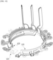
FIG. 11 is a view illustrating a busbar of a motor according to a second embodiment. -
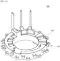
FIG. 12 is a view illustrating a terminal illustrated inFIG. 11 . -
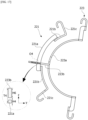
FIG. 13 is a view illustrating a first connecting terminal of a first terminal illustrated inFIG. 12 . -
FIG. 14 is a view illustrating a second connecting terminal of the first terminal illustrated inFIG. 12 . -
FIG. 15 is a view illustrating a second terminal. -
FIG. 16 is a view illustrating an overlap region of the first terminal and the second terminal (neutral terminal). -
FIG. 17 is a view illustrating an overlap region of the first terminal and the second terminal (phase terminal). -
FIG. 18 is a view illustrating an overlap region of the first connecting terminal and the second connecting terminal which are the first terminals. - Hereinafter, exemplary embodiments of the present invention will be described in detail with reference to the accompanying drawings.
- However, the technical spirit of the present invention is not limited to some embodiments which will be described and may be realized using various other embodiments, and at least one component of the embodiments may be selectively coupled, substituted, and used to realize the technical spirit within the range of the technical spirit.
- In addition, unless clearly and specifically defined otherwise by context, all terms (including technical and scientific terms) used herein can be interpreted as having customary meanings to those skilled in the art, and meanings of generally used terms, such as those defined in commonly used dictionaries, will be interpreted by considering contextual meanings of the related technology.
- In addition, the terms used in the embodiments of the present invention are considered in a descriptive sense and not for limiting the present invention.
- In the present specification, unless clearly indicated otherwise by the context, singular forms include the plural forms thereof, and in a case in which "at least one (or one or more) among A, B, and C" is described, this may include at least one combination among all possible combinations of A, B, and C.
- In addition, in descriptions of components of the present invention, terms such as "first," "second," "A," "B," "(a)," and "(b)" can be used.
- The terms are only to distinguish one element from another element, and an essence, order, and the like of the element are not limited by the terms.
- In addition, it should be understood that, when an element is referred to as being "connected or coupled" to another element, such a description may include both of a case in which the element is directly connected or coupled to another element and a case in which the element is connected or coupled to another element with still another element disposed therebetween.
- In addition, in a case in which any one element is described as being formed or disposed "on or under" another element, such a description includes both a case in which the two elements are formed or disposed in direct contact with each other and a case in which one or more other elements are interposed between the two elements. In addition, when one element is described as being disposed "on or under" another element, such a description may include a case in which the one element is disposed at an upper side or a lower side with respect to another element.
-
FIG. 1 is a side cross-sectional view illustrating a motor according to an embodiment. - Referring to
FIG. 1 , the motor according to the embodiment may include arotating shaft 10, arotor 20, a stator 30, and abusbar 100. - The rotating
shaft 10 may be coupled to therotor 20. When a current is supplied so that an electrical interaction occurs between therotor 20 and the stator 30, therotor 20 is rotated and therotating shaft 10 is rotated in conjunction with the rotation of therotor 20. The rotatingshaft 10 may be connected to a steering shaft of a vehicle to transmit power to the steering shaft. - The
rotor 20 is rotated due to the electrical interaction with the stator 30. - The
rotor 20 may include a rotor core and magnets. The rotor core may be formed in a form in which a plurality of thin circular steel plates are stacked or a single cylindrical form. A hole coupled to therotating shaft 10 may be disposed at a central portion of the rotor core. The magnets may be disposed on an outer circumferential surface or an inner portion of the rotor core. - The stator 30 may include a
stator core 31, an insulator 32, and coils 33. The insulator 32 is installed on thestator core 31. Thecoil 33 is wound around the insulator 32. An electrical interaction occurs between thecoil 33 and therotor 20. - The
rotor 20 and the stator 30 may be accommodated in ahousing 40. - A sensing magnet 50 is coupled to the
rotating shaft 10 to operate in conjunction with therotor 20. The sensing magnet 50 is a device for detecting a position of therotor 20. - A sensor configured to detect a magnetic force of the sensing magnet 50 may be disposed on a
circuit board 60. In this case, the sensor may be a Hall integrated circuit (IC). The sensor detects changes in an N-pole and an S-pole of the sensing magnet 50 to generate a sensing signal. - The
busbar 100 is disposed above the stator 30. -
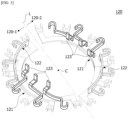
FIG. 2 is a view illustrating a busbar of a motor according to a first embodiment. - Referring to
FIGS. 1 and2 , abusbar 100 may includeterminals 120 disposed in abody 110 having an annular shape. - The
busbar 100 includes thebody 110 and theterminals 120. Thebody 110 may be a mold product formed through an injection molding process. - The
body 110 includes ahole 111 at a central portion thereof. Theterminals 120 may be disposed in thebody 110, and some end portions of theterminals 120 may be disposed to be exposed from thebody 110. An entirety of thebody 110 may have a annular shape. Theterminals 120 may include a phase terminal and a neutral terminal. -
FIG. 3 is a view illustrating the terminal. - Referring to
FIG. 3 , theterminals 120 may be divided into a first group 120-1 and a second group 120-2. The first group 120-1 may be electrically divided from the second group 120-2. Each of the first group 120-1 and the second group 120-2 may includefirst terminals 121 andsecond terminals first terminal 121 is the terminal 120 connecting thecoils 33, and thesecond terminals neutral terminal 122 and aphase terminal 123, respectively. The first group 120-1 and the second group 120-2 may be disposed to be spatially divided by a reference line L passing through a center C of thebusbar 100. -
FIG. 4 is a view illustrating the first terminal illustrated inFIG. 3 . - Referring to
FIG. 4 , astator core 31 may include a firstunit stator core 31A and a secondunit stator core 31B. Thecoils 33 may include afirst unit coil 33A and asecond unit coil 33B. Thefirst unit coil 33A is wound around the firstunit stator core 31A. Thesecond unit coil 33B is wound around the secondunit stator core 31B. - The
first unit coil 33A is an independent coil which is not connected to thesecond unit coil 33B. Thefirst unit coil 33A includes a first end A1 and a second end A2. When thefirst unit coil 33A is wound, any one of the first end A1 and the second end A2 may be a starting end of thefirst unit coil 33A, and the remaining one thereof may be a finishing end thereof. Thesecond unit coil 33B includes a third end B1 and a fourth end B2. Any one of the third end B1 and the fourth end B2 may be a starting end of thesecond unit coil 33B, and the remaining one thereof may be a finishing end thereof. - The
first terminal 121 is a connecting terminal and connects one end of thefirst unit coil 33A and one end of thesecond unit coil 33B. In this case, the term "one end" denotes an end among the first end A1, the second end A2, the third end B1, and the fourth end B2 connected to thefirst terminal 121. For example, inFIG. 4 , one ends may be the first end A1 and the third end B1. - The
second terminals first unit coil 33A and the other end of thesecond unit coil 33B. In this case, the term "the other end" denotes an end among the first end A1, the second end A2, the third end B1, and the fourth end connected to thesecond terminals FIG. 4 , the other ends may be the second end A2 and the fourth end B2. In addition, when the second end A2 is connected to thephase terminal 123, the fourth end B2 may be connected to theneutral terminal 122. Alternatively, when the second end A2 is connected to theneutral terminal 122, the fourth end B2 may be connected to thephase terminal 123. - The first
unit stator core 31A and the secondunit stator core 31B are disposed to be spaced apart from each other in a circumferential direction. Two unit coils 33C and 33D may be disposed between thefirst unit coil 33A and thesecond unit coil 33B in the circumferential direction. -
FIG. 5 is a cross-sectional view illustrating the first terminal illustrated inFIG. 3 . Hereinafter, in the drawings, z denotes a shaft direction of the motor and y denotes a radial direction of the motor. - Referring to
FIG. 5 , thefirst terminal 121 includes afirst body 121a and afirst support 121b. Thefirst body 121a has a curvature. Thefirst support 121b extends from any one portion of thefirst body 121a in the radial direction. In a cross section of thefirst body 121a, a width W1 is greater than a thickness H1. The width W1 is based on the radial direction, and the thickness H1 is based on the shaft direction. -
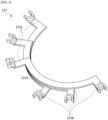
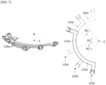
FIG. 6 is a view illustrating the plurality of first terminals, andFIG. 7 is a view illustrating the plurality of first terminals which overlap in a shaft direction. - Referring to
FIG. 6 , thefirst terminal 121 may be provided as the plurality offirst terminals 121. For example, threefirst terminals 121 may be disposed. One regions of thefirst bodies 121a of threefirst terminals 121 may overlap in the shaft direction. Threefirst terminals 121 may be disposed to be shifted by angles R1, R2, and R3 in the circumferential direction so that at least one portions of thefirst bodies 121a overlap in the shaft direction. -
FIG. 8 is a view illustrating the second terminal. - Referring to
FIG. 8 , thesecond terminals second bodies second supports second bodies second bodies second bodies -
FIG. 9 is a view illustrating an overlap region of the first terminal and the second terminal. - Referring to
FIG. 9 , thesecond bodies second terminals first terminal 121 in the shaft direction. - As an example, in an overlap region O1, the
second body 122a of theneutral terminal 122 overlaps thefirst support 121b of thefirst terminal 121 in the shaft direction. The thickness H1 of thefirst body 121b is smaller than the thickness H2 of thesecond body 122a of theneutral terminal 122. Since the thickness H1 of thefirst body 121b is relatively small, a total thickness T1 of theneutral terminal 122 and thefirst terminal 121 may be reduced. - As an example, in an overlap region O2, the
second body 123a of thephase terminal 123 overlaps thefirst body 121a of thefirst terminal 121 in the shaft direction. The thickness H1 of thefirst body 121a is smaller than the thickness H3 of thesecond body 123a of thephase terminal 123. Since the thickness H1 of thefirst body 121a is relatively small, a total thickness T2 of thephase terminal 123 and thefirst terminal 121 may be reduced. - The
first support 121b is provided as a plurality of thefirst supports 121b, thesecond support 122b is provided as a plurality ofsecond supports 122b, and thesecond support 123b is provided as a plurality ofsecond supports 123b. The second supports 122b and 123b may be disposed between thefirst supports 121b. -
FIG. 10 is a view illustrating a modified example of the second terminal. - Referring to
FIG. 10 , although thesecond terminals phase terminals 123 and theneutral terminal 122, thesecond terminals -
FIG. 11 is a view illustrating a busbar of a motor according to a second embodiment. - Referring to
FIG. 11 , abusbar 200 may includeterminals 220 disposed in abody 210 having an annular shape. -
FIG. 12 is a view illustrating the terminal illustrated inFIG. 11 . - Referring to
FIG. 12 , theterminals 220 may include afirst terminal 221 andsecond terminals first terminal 221 is a connecting terminal for connecting acoil 33 and anothercoil 33, and thesecond terminals neutral terminal 222 and aphase terminal 223, respectively. Thefirst terminal 221 may be provided as a plurality offirst terminals 221, thesecond terminal 222 may be provided as a plurality ofsecond terminals 222, thesecond terminal 223 may be provided as a plurality ofsecond terminals 223, and thefirst terminals 221 andsecond terminals -
FIG. 13 is a view illustrating a first connecting terminal of the first terminal illustrated inFIG. 12 . -
FIG. 14 is a view illustrating a second connecting terminal of the first terminal illustrated inFIG. 12 . - Referring to
FIGS. 13 and14 , thefirst terminals 221 may include a first connectingterminal 221A and a second connectingterminal 221B. - The first connecting
terminal 221A and the second connectingterminal 221B may respectively include bent portions 221Aa and 221Ba, third bodies 221Ab and 221Bb, and third supports 221Ac and 221Bc. - The bent portions 221Aa and 221Ba are bent from the third bodies 221Ab and 221Bb, respectively. The bent portions 221Aa and 221Ba may have curvatures. The third bodies 221Ab and 221Bb extend from both ends of the bent portions 221Aa and 221Ba, respectively. The third supports 221Ac and 221Bc may be disposed to extend from one portions of the third bodies 221Ab and 221Bb in a radial direction, respectively.
- In cross sections of the bent portions 221Aa and 221Ba, widths W4a and W4b are greater than thicknesses H4a and H4b, respectively. The widths W4a and W4b are based on the radial direction, and the thicknesses H4a and H4b are based on a shaft direction.
- The bent portion 221Aa of the first connecting
terminal 221A has a shape extending inward from the third body 221Ab. The bent portion 221Ba of the second connectingterminal 221B has a shape extending outward from the third body 221Bb. -
FIG. 15 is a view illustrating the second terminal. - Referring to
FIG. 15 , thesecond terminals fourth bodies fourth supports fourth bodies fourth bodies fourth bodies -
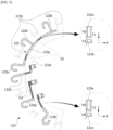
FIG. 16 is a view illustrating an overlap region of the first terminal and the second terminal (neutral terminal). - The
second terminals bent portion 221a of thefirst terminal 221 in the shaft direction. - Referring to
FIG. 16 , as an example, in an overlap region O3, theneutral terminal 222 overlaps thebent portion 221a in the shaft direction. A thickness H4 of thebent portion 221a is smaller than a thickness H5 of theneutral terminal 222. Since the thickness H4 of thebent portion 221a is relatively small, a total thickness T3 of theneutral terminal 222 and thefirst terminal 221 may be reduced. -
FIG. 17 is a view illustrating an overlap region of the first terminal and the second terminal (phase terminal). - As an example, in an overlap region O4, the
fourth support 223b of thephase terminal 223 overlaps thebent portion 221a of thefirst terminal 221 in the shaft direction. The thickness H4 of thebent portion 221a is smaller than a thickness H6 of thefourth support 223b of thephase terminal 223. Since the thickness H4 of thebent portion 221a is relatively small, a total thickness T4 of thephase terminal 223 and thefirst terminal 221 may be reduced. -
FIG. 18 is a view illustrating an overlap region of the first connecting terminal and the second connecting terminal which are the first terminals. - Referring to
FIG. 18 , thefirst terminals 221 may include a plurality of connecting terminals. Thefirst terminals 221 may include a first connectingterminal 221A and a second connectingterminal 221B. The first connectingterminal 221A and the second connectingterminal 221B overlap in the shaft direction. - As an example, in an overlap region O5, the third support 221Ac of the first connecting terminal 221A overlaps the bent portion 221Ba of the second connecting terminal 221B in the shaft direction. A thickness H4 of the bent portion 221Ba is smaller than a thickness H7 of the third support 221Ac. Since the thickness H4 of the bent portion 221Ba is relatively small, a total thickness T5 of the bent portion 221Ba and the
first terminal 221A may be reduced. Meanwhile, the third bodies 221Ab and 221Bb of the plurality of connecting terminals may not overlap in the shaft direction.
Claims (8)
- A motor comprising:a stator (30) including coils (33);a rotor (20) disposed inside the stator (30); anda busbar (200) disposed above the stator (30),wherein the stator (30) includes a first unit stator core (31A) and a second unit stator core (31B),the coils (33) include a first unit coil (33A) and a second unit coil (33B), andthe busbar (200) includes a body (210) and a plurality of terminals (220) connected to the coils (33) of the stator (30),wherein the plurality of terminals (220) include first terminals (221) and second terminals (222, 223),the first unit coil (33A) is wound around the first unit stator core (31A),the second unit coil (33B) is wound around the second unit stator core (31B),one end of the first unit coil (33A) and one end of the second unit coil (33B) are connected to the first terminals (221), andthe other end of the first unit coil (33A) and the other end of the second unit coil (33B) are connected to the second terminals (222, 223),wherein the second terminals (222, 223) include a neutral terminal (222) and a plurality of phase terminals (223),wherein the other end of the first unit coil (33A) is connected to the neutral terminal, and the other end of the second unit coil (33B) is connected to one of the plurality of phase terminals (223),characterized in that the first terminals (221) include bent portions (221Aa, 221Ba) having curvatures, third bodies (221Ab, 221Bb) extending from both ends of each of the bent portions (221Aa, 221Ba) along a circumferential direction, respectively, and third supports (221Ac, 221 Bc) respectively disposed to extend from one portions of the third bodies (221Ab, 221Bb) in a radial direction,wherein the second terminals (222, 223) respectively include fourth bodies (222a, 223a) having curvatures, and fourth supports (222b, 223b) respectively extending from one portions of the fourth bodies (222a, 223a) in a radial direction,the bent portions (221Aa, 221Ba) having radial width (W4a, W4b) greater than thicknesses (H4a, H4b) in an axial direction of a shaft (10), respectively, andfourth bodies (222a, 223a) having radial width (W5, W6) smaller than thicknesses (H5, H6) in the axial direction, respectively,wherein the first terminals (221) do not overlap in the axial direction, and the first terminals (221) and the second terminals (222, 223) include overlap regions in the axial direction,wherein the neutral terminal (222) and the fourth support (223b) of the phase terminal (223) respectively overlap the bent portion (221a) of the first terminal in the axial direction.
- The motor of claim 1, wherein the second terminals (222, 223) include two groups each including the neutral terminal (222) and the plurality of phase terminals (223),
wherein the two groups are electrically divided. - The motor of claim 1, wherein the thickness of the first terminal (221) is smaller than the thicknesses of the second terminals (222, 223) in the overlap region.
- The motor of any one of claims 1 to 3, wherein:the first terminals include first bodies having curvatures and first supports extending from one portions of the first bodies in a radial direction; andat least any one of the first body (110) and the first supports overlaps the second terminal in a shaft direction.
- The motor of claim 1, wherein:
a width in the radial direction is smaller than a thickness in a vertical direction in each of the third body (221b) and the third support (221c). - The motor of claim 5, wherein the bent portion (221a) is disposed to be lower than the third body (221b) and the third support (221c).
- The motor of claim 1, wherein:the first terminals (221) include a plurality of connecting terminals (221A, 221B); andthird bodies (221Ab, 221Bb) of the plurality of connecting terminals (221A, 221B) do not overlap in the axial direction.
- The motor of claim 7, wherein the bent portion (221a) of one of the plurality of connecting terminals (221A, 221B) overlaps the third body (221b) or the third support (221c) of another of the plurality of connecting terminals (221A, 221B) in the axial direction.
Applications Claiming Priority (2)
| Application Number | Priority Date | Filing Date | Title |
|---|---|---|---|
| KR1020180108451A KR20200029876A (en) | 2018-09-11 | 2018-09-11 | Motor |
| PCT/KR2019/011807 WO2020055150A1 (en) | 2018-09-11 | 2019-09-11 | Motor |
Publications (3)
| Publication Number | Publication Date |
|---|---|
| EP3852247A1 EP3852247A1 (en) | 2021-07-21 |
| EP3852247A4 EP3852247A4 (en) | 2021-11-17 |
| EP3852247B1 true EP3852247B1 (en) | 2024-04-10 |
Family
ID=69778587
Family Applications (1)
| Application Number | Title | Priority Date | Filing Date |
|---|---|---|---|
| EP19858866.7A Active EP3852247B1 (en) | 2018-09-11 | 2019-09-11 | Motor |
Country Status (6)
| Country | Link |
|---|---|
| US (1) | US20220069659A1 (en) |
| EP (1) | EP3852247B1 (en) |
| JP (1) | JP7383711B2 (en) |
| KR (1) | KR20200029876A (en) |
| CN (1) | CN112673555A (en) |
| WO (1) | WO2020055150A1 (en) |
Families Citing this family (4)
| Publication number | Priority date | Publication date | Assignee | Title |
|---|---|---|---|---|
| KR20190095748A (en) * | 2018-02-07 | 2019-08-16 | 엘지이노텍 주식회사 | Motor |
| CN114556755B (en) * | 2019-10-10 | 2023-07-14 | Lg伊诺特有限公司 | Motor |
| JP7441072B2 (en) * | 2020-02-25 | 2024-02-29 | 株式会社Subaru | stator |
| KR20230109264A (en) * | 2022-01-13 | 2023-07-20 | 엘지이노텍 주식회사 | Motor |
Family Cites Families (17)
| Publication number | Priority date | Publication date | Assignee | Title |
|---|---|---|---|---|
| JP3613262B2 (en) * | 2002-04-26 | 2005-01-26 | 三菱電機株式会社 | Rotating electric machine and manufacturing method thereof |
| JP4654103B2 (en) | 2005-10-05 | 2011-03-16 | 矢崎総業株式会社 | Power distribution member |
| JP4939244B2 (en) * | 2007-01-31 | 2012-05-23 | アイチエレック株式会社 | Winding connection device for rotating machine, stator for rotating machine and rotating machine |
| JP4743167B2 (en) * | 2007-05-29 | 2011-08-10 | トヨタ自動車株式会社 | Terminal module for rotating electric machine and rotating electric machine |
| JP2010200400A (en) * | 2009-02-23 | 2010-09-09 | Nippon Densan Corp | Stator, bus bar unit, motor, and power steering device |
| JP5740931B2 (en) * | 2010-03-03 | 2015-07-01 | 日本電産株式会社 | Split stator and motor |
| JP2012110188A (en) * | 2010-11-19 | 2012-06-07 | Nippon Densan Corp | Intermediate connection member, stator, and motor |
| JP5847543B2 (en) * | 2011-11-08 | 2016-01-27 | 株式会社ミツバ | Busbar unit and brushless motor |
| JP5930801B2 (en) * | 2012-03-30 | 2016-06-08 | 日立オートモティブシステムズ株式会社 | In-vehicle motor and electric power steering apparatus using the same |
| JP6163357B2 (en) * | 2013-05-30 | 2017-07-12 | 株式会社ミツバ | Electric motor and motor with reduction gear |
| KR20150040527A (en) * | 2013-10-07 | 2015-04-15 | 엘지이노텍 주식회사 | Motor |
| US10211699B2 (en) | 2013-10-21 | 2019-02-19 | Nidec Corporation | Motor and bus bar unit having overlapping bridge portions |
| JP6539997B2 (en) | 2014-11-25 | 2019-07-10 | 日本電産株式会社 | motor |
| US10622861B2 (en) * | 2015-03-31 | 2020-04-14 | Aisin Aw Co., Ltd. | Stator and bus bar connector configuration |
| US10855132B2 (en) * | 2015-07-22 | 2020-12-01 | Top Co., Ltd. | Bus bar unit, rotary electric machine having the same, and manufacturing method of bus bar unit |
| JP6638295B2 (en) * | 2015-09-30 | 2020-01-29 | アイシン精機株式会社 | Rotating electric machine |
| JP6706583B2 (en) | 2017-02-16 | 2020-06-10 | 株式会社ミツバ | Brushless motor |
-
2018
- 2018-09-11 KR KR1020180108451A patent/KR20200029876A/en not_active Application Discontinuation
-
2019
- 2019-09-11 JP JP2021537424A patent/JP7383711B2/en active Active
- 2019-09-11 WO PCT/KR2019/011807 patent/WO2020055150A1/en unknown
- 2019-09-11 EP EP19858866.7A patent/EP3852247B1/en active Active
- 2019-09-11 CN CN201980059283.8A patent/CN112673555A/en active Pending
- 2019-09-11 US US17/275,017 patent/US20220069659A1/en active Pending
Also Published As
| Publication number | Publication date |
|---|---|
| EP3852247A4 (en) | 2021-11-17 |
| EP3852247A1 (en) | 2021-07-21 |
| WO2020055150A1 (en) | 2020-03-19 |
| KR20200029876A (en) | 2020-03-19 |
| JP2022500992A (en) | 2022-01-04 |
| JP7383711B2 (en) | 2023-11-20 |
| US20220069659A1 (en) | 2022-03-03 |
| CN112673555A (en) | 2021-04-16 |
Similar Documents
| Publication | Publication Date | Title |
|---|---|---|
| EP3852247B1 (en) | Motor | |
| EP3098947B1 (en) | Stator and motor using the same | |
| US11670980B2 (en) | Motor having terminals with unified shapes for positioning | |
| KR102146023B1 (en) | Motor and electronic power steering system having the same | |
| US11394267B2 (en) | Motor | |
| WO2009017257A2 (en) | Motor | |
| CN108370188B (en) | Insulator and motor including the same | |
| US11799351B2 (en) | Motor | |
| US11362559B2 (en) | Motor | |
| KR20210077405A (en) | Motor | |
| CN113825983A (en) | Redundant rotary transformer device and electric power steering device | |
| KR102655249B1 (en) | Motor and electronic power steering system having the same | |
| KR102412391B1 (en) | Motor and electronic power steering system having the same | |
| US20230307983A1 (en) | Motor | |
| US20220399776A1 (en) | Motor | |
| CN114830501A (en) | Motor | |
| JP6488100B2 (en) | Electric motor | |
| KR20200098456A (en) | Motor and electronic power steering system having the same | |
| KR20210095381A (en) | Motor | |
| KR20210077404A (en) | Motor |
Legal Events
| Date | Code | Title | Description |
|---|---|---|---|
| STAA | Information on the status of an ep patent application or granted ep patent |
Free format text: STATUS: THE INTERNATIONAL PUBLICATION HAS BEEN MADE |
|
| PUAI | Public reference made under article 153(3) epc to a published international application that has entered the european phase |
Free format text: ORIGINAL CODE: 0009012 |
|
| STAA | Information on the status of an ep patent application or granted ep patent |
Free format text: STATUS: REQUEST FOR EXAMINATION WAS MADE |
|
| 17P | Request for examination filed |
Effective date: 20210408 |
|
| AK | Designated contracting states |
Kind code of ref document: A1 Designated state(s): AL AT BE BG CH CY CZ DE DK EE ES FI FR GB GR HR HU IE IS IT LI LT LU LV MC MK MT NL NO PL PT RO RS SE SI SK SM TR |
|
| A4 | Supplementary search report drawn up and despatched |
Effective date: 20211018 |
|
| RIC1 | Information provided on ipc code assigned before grant |
Ipc: H02K 3/52 20060101ALI20211012BHEP Ipc: H02K 5/22 20060101AFI20211012BHEP |
|
| DAV | Request for validation of the european patent (deleted) | ||
| DAX | Request for extension of the european patent (deleted) | ||
| STAA | Information on the status of an ep patent application or granted ep patent |
Free format text: STATUS: EXAMINATION IS IN PROGRESS |
|
| 17Q | First examination report despatched |
Effective date: 20230523 |
|
| GRAP | Despatch of communication of intention to grant a patent |
Free format text: ORIGINAL CODE: EPIDOSNIGR1 |
|
| STAA | Information on the status of an ep patent application or granted ep patent |
Free format text: STATUS: GRANT OF PATENT IS INTENDED |
|
| GRAS | Grant fee paid |
Free format text: ORIGINAL CODE: EPIDOSNIGR3 |
|
| GRAA | (expected) grant |
Free format text: ORIGINAL CODE: 0009210 |
|
| STAA | Information on the status of an ep patent application or granted ep patent |
Free format text: STATUS: THE PATENT HAS BEEN GRANTED |
|
| INTG | Intention to grant announced |
Effective date: 20240214 |
|
| AK | Designated contracting states |
Kind code of ref document: B1 Designated state(s): AL AT BE BG CH CY CZ DE DK EE ES FI FR GB GR HR HU IE IS IT LI LT LU LV MC MK MT NL NO PL PT RO RS SE SI SK SM TR |
|
| REG | Reference to a national code |
Ref country code: GB Ref legal event code: FG4D |
|
| REG | Reference to a national code |
Ref country code: CH Ref legal event code: EP |